REPRINT R E PAP TECHNICAL PREY A - Babcock Power
16
RST-88 CASE HISTORY ARCHBALD POWER by Stephen B . Gross, Plant Manager UC Operating Services and Dietmar J . Kestner, Product Manager FBC Systems Riley Stoker Corporation Presented at The Council of Industrial Boiler Owners (CIBO) Sixth Annual Fluidized Bed Conference December 10-11, 1990 Harrisburg, Pennsylvania R I L E Y Riley Stoker Corporation Post Office Box 15040 Worcester, MA 01615-0040
Transcript of REPRINT R E PAP TECHNICAL PREY A - Babcock Power

APREYTECHNICALPAPERREPRINT
RST-88
CASE HISTORYARCHBALD POWER
byStephen B. Gross, Plant Manager
UC Operating Servicesand
Dietmar J. Kestner, Product Manager FBC SystemsRiley Stoker Corporation
Presented atTheCouncil of Industrial Boiler Owners (CIBO)
Sixth Annual Fluidized Bed ConferenceDecember 10-11, 1990
Harrisburg, Pennsylvania
R I LEYRileyStoker Corporation
Post Office Box 15040Worcester, MA 01615-0040
cstcyr
Now Part of Babcock Power Inc. www.babcockpower.com

INTRODUCTION
Several anthracite culm-fired FBCboilers havebeen constructed in Pennsylvania during recentyears. Culm is a by-product of the coal indus-try and is today being used as an energy sourceto provide heat and power to industry andutilities . As another benefit, part of the mou-ntains of culm located throughout Northeast-ern Pennsylvania will be eliminated and theland reclaimed. Fluidized bed combustion isregarded as the most suitable combustiontechnology to burn the low-calorific, low-reactive fuel .
The Archbald Power Cogeneration Plant is ananthracite culm FBC facility located north ofScranton, in Archbald Borough. The facilityincludes a 20 MW power plant and a green-house. A simplified flow diagram is illustratedin Figure 1. Refer to Appendix for figuresand tables .
Riley Energy Systems constructed the facilityon a turnkey basis. The FBC boiler is rated at200,000 lb/hr output to a full condensingturbine generator. The boiler design parame-ters are outlined in Table 1 . Electricity gener-ated is sold to Pennsylvania Power and LightCompany. Low-pressure steam extracted fromthe turbine will heat water for the integratedgreenhouse facility. The Project is located onan undeveloped property comprising theArchbald culm banks. Approximately 600 tonsper day of culm, as specified in Table 2, will bereclaimed from the piles, crushed and burnedin the power plant. Limestone is fed into theboiler to minimize sulfur emissions duringcombustion . Particulate emissions are con-trolled by a fabric filter baghouse. All residuesgenerated by the facility will be non-hazardousand will be landfilled in abandoned coal minepits-located on-site.
MSF13 BOILER
The Multi-Solid Fluidized Bed (MSFB) boilerwhich had initially been installed to burn the
culm is depicted in Figure 2. The 11YISFBprocess has been described on several occa-sions and references should be used for amore detailed description (1).Essentially, the combustor vessel is dividedinto two zones with different cross sectionalareas. The lower reducing zone contains adense bed of large particles of rounded silicagravel (approximately 1/2" x 3/4") . Fuel andlimestone are added into this region andprimary combustion air is introduced throughan air distribution grid . The quantity of prima-ry air is approximately 30% of the total com-bustion air whereas the remaining 70% is.provided to the upper oxidizing zone as sec-ondary air (55%) and vent air (15%) from anexternal heat exchanger (EHE). The densebed normally operates at a superficial fluid-izing velocity of about 25 ft/sec and the upperzone at 30 ft/sec, respectively.
The hot combustion gas and recirculatingparticles leave the combustor and enter twoparallel cyclones, where the heavier particlesare separated from the gas stream and fall intothe EHE. The hot gas passes through theconvection zone where heat is absorbed by thehigh and low temperature superheaters andconvection walls. The gas then passes throughthe economizer and airheater before exitingthe unit . The solids collected in the EHE arereturned to the combustor either non-cooledthrough the hot recycle to control solids loador cooled through cold recycle lines to controlcombustion temperature.
Steam is produced by two means simultaneous-ly . First, steam is generated in the naturalcirculation combustor water-walls and via acontrolled circulation evaporator in the EHEin tubes submerged within a bed of fluidizedsand and ash . Combustion air is supplied tothe boiler by separate fans for primary, sec-ondary, andEHE air through separate sectionsof the tubular airheater before entering the?rrespective air plenums. The primary air isdirected through a propane-fired duct burnerfor startup purposes. The flue gases leaving

the boiler are drawn through the baghouse anddischarged to the stack by an induced draft(ID) fan.
The boiler was initially fired in 1988. Due tothe significant departure of anthracite culmfrom fuels in previous fluid bed boilers, anumber of severe operating problems occurr-ed . The low fuel reactivity, deeply stagedcombustion, and insufficient combustor resi-dence time resulted in poor carbon utilization .This, coupled with the high potassium andillite content of the ash, resulted in a sinteringphenomena within the hot recycle system ofthe EHE and clinkering of the dense bedduring fan trips. As a consequence, reliableoperation at the desired steam output gondi-tions could not be achieved .
To remedy these problems, a variety of poten-tial solutions were investigated in detail, rang-ing from modifications of the existing combust-or and its ancillaries to a complete exchange ofthe combustion system which has finally beenapplied by adapting Deutsche Babcock's Circo-fluid System.
MSFB VERSUS CIRCOFLUID SYSTEM
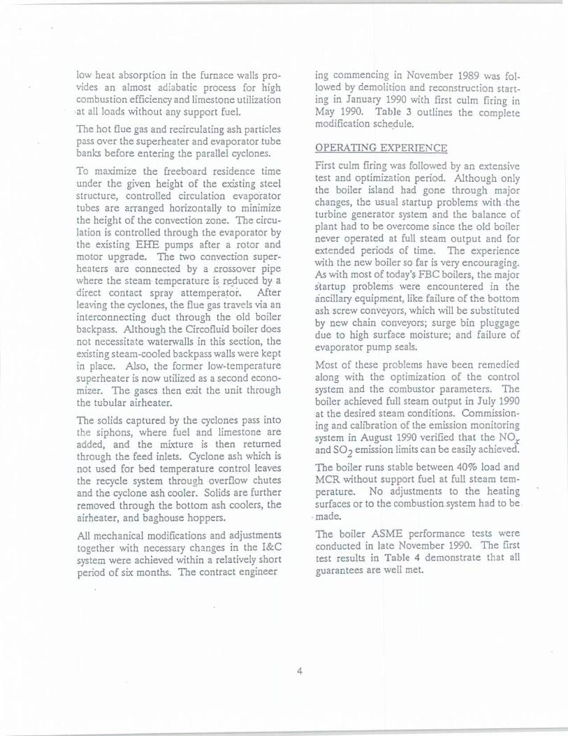
The final decision as to converting the MSFBunit to a Circofluid boiler was preceded by anengineering study in June 1989 to verify themechanical feasibility of a conversion in theexisting boiler structure. The study was con-ducted by VKW, a Deutsche Babcock affiliatebased on their previous FBC experience con-sidering the very special combustion behaviorof culm .To emphasize the significant design changes,Figure 3 outlines the major differences be-tween the MSFB and the Circofluid systembased on the Archbald project.
Basically, a Circofluid boiler consists of twoboiler passes which are connected by ashrecycle cyclones . The first pass includes, indirection of the gas flow, the fluidizing airplenum, a dense bed zone of fuel ash, thefreeboard and one part of the convection
heating surfaces . The flue gas enters thecyclone at about 800°F. Most of the fly ash iscaptured there and then recycled through asiphon system to the dense bed. The remain-ing heating surfaces, i.e ., economizer andairheater, are arranged in the second boilerpass .
The preheated combustion air is split into 70%primary air and 30% secondary air.The most significant characteristic of a Circo-fluid boiler is the control of the combustiontemperature. The dense bed temperatureremains constant at approximately 1,600°Fover the entire load range. The bed is cooledby the cold cyclone ash. The recirculation ashflow is controlled by varying the air flow to thesiphons. The heat absorbed by the recirculat-ed ash is then transported through the free-board and transferred to the convection heat-ing surfaces before the cyclone. By this ar-rangement, almost 90% of the available heat istransferred in the first pass, whereas in theMSFB system the combustor heat duty is only20% . .For a more detailed description of theCircofluid process, refer to reference (2). Inview of before mentioned system differences,the modification of the Archbald boiler re-quired major changes of:
> the combustor and heating surfacesarrangement
" the ash recirculation system and" the combustion air system
BOILER CONVERSION
As the next step, a number of combustion testswere conducted in Deutsche Babcock's 7 MMBTU/hr Circofluid test facility in August 1989.More than 100 tons of anthracite culm wereburned by varying all important combustionparameters such as temperatures, air splits,combustor velocities, and residence time toverify the previous assumptions on boilerdesign and performance.
The combustion tests were followed by areview of the preliminary design and an in-

depth cost analysis of the conversion resultingin release of detail contract engineering inNovember 1989 .
Because of the great difference between theMSFB and the Circofluid system, the followingprocess-related changes had to be made(fur-ther illustrated in Figure 4) :
o Combustor
The old combustor was substi-tuted by a new combustor andconvection zone with morethan double the cross-sectionalarea .
Heating Surfaces
The EHE and the final pen-dant superheater were substi-tuted by superheat and evapo-rator tubes in the convectionzone above the freeboard.
e
Ash Recirculation
The low recycle temperatureallowed for a significant reduc-tion in the Circofluid recyclesystem size and weight . Twonew cyclones were installedalong with the necessary recy-cle lines and siphon boxes.
Ancillary Equipment
Figure 5 outlines other pro-cess-related changes made(new equipment in dottedlines) .
The maximum culm particle size of the MSFBunit had been 1/2 " whereas 3/8" proved to bethe optimum number for the Circofluid boiler .Further crushing is now achieved by two addi-tional 100% secondary crushers . Two (redun-dant) drag chain feeders to the combustorwere added to feed the culm to the siphonoutlet chutes rather than separately to thecombustor side walls.
New feedwater cooled combustor bottom and
cyclone ash coolers recover a significant por-tion of the sensible heat of the solids . Thisallowed the existing vacuum ash disposalsystem to be utilized without additional ashconveying equipment.
The optimum combustion of the culm isachieved while maintaining a high primary airflow. Because of the differences in air split,pressure and arrangement, the installation ofnew air fans was determined as the most eco-nomical solution . To heat up the higher densebed inventory of the Circofluid boiler, thecapacity of the propane-fired startup burnerwas increased.
Along with the before mentioned technology-related changes, further modifications weremade to,improve the unit efficiency and avail-ability. These modifications included an exten-sion of airheater surface to further reduce theexit gas temperature and expansion of thebaghouse for improved on-line service.
CIRCOFLUID BOILER
Figure 6 depicts a more detailed view of theCircofluid boiler after conversion .
The fluidized bed is located in the lowerportion of the waterwall combustor. It consistsof a bed of ash, fuel, and limestone.
The fuel and limestone is fed into the bedthrough the ash siphon outlet chutes . Thelimestone sorbent reacts with the sulfur in thefuel to reduce the S02 emissions.
Primary air enters through the startup burnerduct and the air distributors located below thefluidized bed. NOX emission control is accom-plished by introducing secondary air to thefreeboard above the dense bed at two levels :
The dense bed and the freeboard water-wallsare lined with thin, 1 1/z", refractory tiles toreduce both tube erosion and heat absorptionby the waterwalls. This tile system has beenselected because monolithic refractory systemswere unable to meet the stringent warrantyrequirements specified by Riley Stoker. The
low heat absorption in the furnace walls pro-vides an almost adiabatic process for highcombustion efficiency and limestone utilizationat all loads without any support fuel .The hot flue gas and recirculating ash particlespass over the superheater and evaporator tubebanks before entering the parallel cyclones .To maximize the freeboard residence timeunder the given height of the existing steelstructure, controlled circulation evaporatortubes are arranged horizontally to minimizethe height of the convection zone . The circu-lation is controlled through the evaporator bythe existing EHE pumps after a rotor andmotor upgrade . The two convection super-heaters are connected by a crossover pipewhere the steam temperature is reduced by adirect contact spray attemperator. Afterleaving the cyclones, the flue gas travels via aninterconnecting duct through the old boilerbackpass . Although the Circofluid boiler doesnot necessitate waterwalls in this section, theexisting steam-cooled backpass walls were keptin place . Also, the former low-temperaturesuperheater is now utilized as a second econo-mizer. The gases then exit the unit throughthe tubular airheater .The solids captured by the cyclones pass intothe siphons, where fuel and limestone areadded, and the mixture is then returnedthrough the feed inlets . Cyclone ash which isnot used for bed temperature control leavesthe recycle system through overflow chutesand the cyclone ash cooler. Solids are furtherremoved through the bottom ash coolers, theairheater, and baghouse hoppers.
All mechanical modifications and adjustmentstogether with necessary changes in the I&Csystem were achieved within a relatively shortperiod of six months . The contract engineer
ing commencing in November 1989 was fol-lowed by demolition and reconstruction start-ing in January 1990 with first culm firing inMay 1990 . Table 3 outlines the completemodification schedule.
OPERATING EXPERIENCEFirst culm firing was followed by an extensivetest and optimization period. Although onlythe boiler island had gone through majorchanges, the usual startup problems with theturbine generator system and the balance ofplant had to be overcome since the old boilernever operated at full steam output and forextended periods of time . The experiencewith the new boiler so far is very encouraging .As with most of today's FBC boilers, the majorstartup problems were encountered in theancillary equipment, like failure of the bottomash screw conveyors, which will be substitutedby new chain conveyors ; surge bin pluggagedue to high surface moisture ; and failure ofevaporator pump seals .Most of these problems have been remediedalong with the optimization of the controlsystem and the combustor parameters . Theboiler achieved full steam output in July 1990at the desired steam conditions . Commission-ing and calibration of the emission monitoringsystem in August 1990 verified that the NOXand S02 emission limits can be easily achieved .
The boiler runs stable between 40% load andMCR without support fuel at full steam tem-perature . No adjustments to the heatingsurfaces or to the combustion .system had to be .made.The boiler ASME performance tests wereconducted in late November 1990. The firsttest results in Table 4 demonstrate that allguarantees are well met .

TABLE 1
Boiler Design Parameters
Steam Flaw
200,000 lb/hr
Steam Temperature
915°F
Steam Pressure
1,335 psig
Feedwater Temperature
420°F
Sulfur Capture
90%
S02 Emission, .' % 02 dry
0.23 lb/MM BTU
NOx Emission
0.25 lb/MM BTU
Particulate Emission
0.03 lb/MM BTU
TABLE 2 Fuel Analvsis
Design Range
Higher Heating Value BTU/lb 4,241 3,400 to 5,400
Ash, % by weight 58.59 50 to 65
Moisture % 5.35 max 10
Sulfur, % 0.31 max 0.4

TABLE 3
Modification Schedule
Feasibility Study June 1989
Test Burns in Germany August 1989
Engineering Release November 6, 1989
Demolition January 2, 1990
First Fire May 28, 1990
MCR July 30, 1990
Performance Test November 28, 1990
Emissions Compliance Test December 6, 1990
TABLE 4
Boiler Performance
Adjusted for Design Fuel (4,240 BTUIlb)
Guarantee Nov. 28 Test
Boiler Efficiency 83.21 83.85
NOX Emission, lb/MM BTU 0.25 0.08
S02 Emission, lb/MM BTU 0.23 0.20
S02 Retention % 85 90

Place, W. J.; Bemston, K.; "CirculatingFluidized Bed C-)mbustion via MSFB ,American Power Conference 49thAnnual Meeting; Chicago, Illinois ;April 1987.
REFERENCES
2. Tigges, KD.; Kestner, D.; "Experiencewith the Commissioned Operation ofthe Saarbrucken Circofluid Boiler";proceedings of the 10th InternationalConference on FBC; San Francisco,California ; May 1989.

APPENDIX

DELIVE+' - DLIMESTONE
CONTROLLEDENVIRONMENT
GROWINGFACILITY(CEG)
CULM PREPARATION BUILDING
RAW CULM -,
SIMPLIFILD DIAGRAM OF ARCHUALD IjLAN i
WARM WATER
ROCK REJECTS
LIMESTONESTORAGE SILO
RILEY STOK ER\TURNKEY
1_-JCOOLINGTOWER

P,IISt= D
DOILER(Detailed Side E!evation)
Figure 2
MSFQ
CIRCOFLUID CONVERSION FOR ARCHBALD
CIRCOFLUID

30x
CIRCOFLUID88y
HEAT DUTY
12%
20%
HEAT DUTY
407
EVAPORATOR
SUPERHEAT.
960'C1760' F
4 .3 m/sec .14 ft/sec .
870'C1600' F
70%
SECONDARY PRIMARYAIR
AIR
430' C800' F
CIRCORLUID VERSUS MSrB
AIRHEATER
MSFB
SECONDARY PRIMARY
EHEAIR
AIR
AIf?
SUPER-11EATER
AIRfiEATER

RAW FUELRECEIVINGHOPPER
BELT
P~CR
IIMA'JSI1
BELT
RYIER
:UIl(SIL0'
SECONDARYrf-l t~,
CRUSIIERS'~" -Ij
CL13
PNEUMATICTRUCK
RECEIVER
DIN VEN'rFILTER
BUCKETELEVATORS
THE ARCHBALD PROJECTARCHBALD, PI?NNSYLVANIA
RILEY STOKER CORPORATIONPROCESS FLOW DIAGRAM
-- NEW EQUIPMENT- EXISTING EQUIPMENT
ASIILEGEND
TANKS
BAGHOUSEFORCED
r-
r -F - 1- -1DRAFT-(1
PRAIARYI
.JNFAN II00STERDIN VENT
IANTI
r_u-_L--___ I IIEATERr__,
I II I~~APO:ZAT~t
°aI I
a
I
S~JPERIIFATJIR
I I
0
I
IVAPORAT0
i
I
II
II
II
II
IbrCONDARY_
I
I AIR
PRIMARY
/,CT
AIR
I AITT-I
RECEIVER/FII;fER ~~
CYCLONEASH
COOLER
ROTARY
Sc
I -"-BEI) ASIIdc~'VALVE
'b a }I
I-1aK
COOLERS
Figure 5
I .D .FAN
ASII STORAGESIL0
W///-STACK
Ii II :r1?R
EXIIAi1STI ,
FILTER I:XIIAIJS't'l ,l-n
ItT:CI;,IVI;I2/F I I' I
RDIN VENTFII :YER
If,) 0
SIT- CONDITIONEII -~ 'I'0~I~ItU(:K

CIRCOI= LUl u
E301LER(Detailed Side Elevation)