REPORTNo - NASA · NET kiE.A.HJRED PITCHING TIOkIENT .~BOUT -w AXIS* OF 310 DEL HOLDER ~ POU~D....
12
. REPORTNo.266 AIR FORCE AND MOMENT FOR N-X) WING WITH CERTAIN CUT-OUTS By R. FL SMITH Aerodynamical Laboratory, lhuwm of Construction and Repair, U. S. Navy 239 https://ntrs.nasa.gov/search.jsp?R=19930091334 2019-03-17T02:32:44+00:00Z
Transcript of REPORTNo - NASA · NET kiE.A.HJRED PITCHING TIOkIENT .~BOUT -w AXIS* OF 310 DEL HOLDER ~ POU~D....
.
REPORT No.266
AIR FORCE AND MOMENT FOR N-X) WING
WITH CERTAIN CUT-OUTS
By R. FL SMITH
Aerodynamical Laboratory, lhuwm of Construction
and Repair, U. S. Navy
239
https://ntrs.nasa.gov/search.jsp?R=19930091334 2019-03-17T02:32:44+00:00Z


REPORT NO. 266
AIR FORCE AN) MOMENT FOR N-20 TYING WITH CERTAIN CUT-OUTS
By R. H. SMITH
INTRODUCTION
The airplane designer often finds it necessary, in meeting the requirements of -risibility,to remove area or to otherwise locally distorfi the plan or section of an airplana wing. Thisreport, prepared for the Bureau of Aeronautics January 151 1925, and submitted for publicationto the ATational Advisory Committee for Aeronautics l?o-iernber 29, 1926, contains bhe experi-mental resuIts of tests on six 5 by 30 inch !4-20 wing models, cut out or distorted in differentways, which were conducted in the 8 by 8 foot wind tunnel of the ATavy Aerodyrmmical Labora-tory in Washington in 1924.
The measured and clerked results are gi-ren tithou~ correction for Vi/v or for w-aII effectand for standard air de~%ity, p = 0.00237 slug per cubic foot.
DESCRIPTION OF MODELS
The principal dimensions and specified offsets of the six models are ghen in Figure 1; theirfull-scale sectiori -views in Figure 4. They were made of @y mahogany and wu-nkhed, thea”satisfactorily -rerSed by application of their steel tempIates. The two wings, composingmodel N-20A, were assembled b-y means of two streamlined steel members in the positionof the spars. The other models were made completely of -wood.
RESULTS
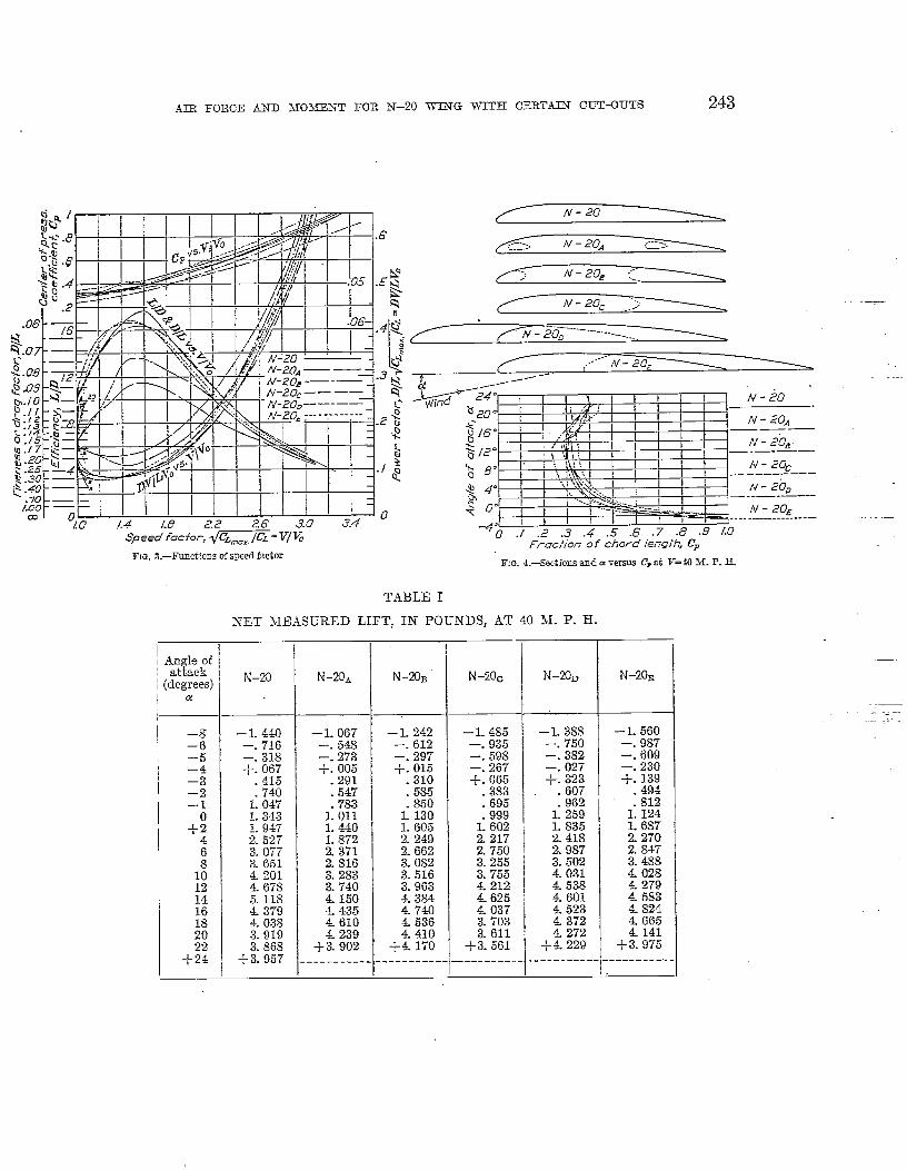
Tables I to XEKI gke the numerid resuIts of the tests, all of which were made at 40 miIesper hour; the &t three containing tesi data, the next four the lift and drag coefficient+ and thenext si~ the speed and po-wer factors, efficiencies, &d center of pressure coefficients. The data,excepting for K= and lZY coefficients, are pIott-ed in Figures ?, 3, and 4. TabIe XIV gives thechief structural and aerodynamic charwteristies of the modek.
While no anaIysis of the results is attempted, a few- conclusions are outstmding. Althoughthe N-20 wing with no cut-out or distortion has the largest -rakes of L/Dm~tium, CL maxi-mum and maximum speed ratio, some of the dktorted forms outperform it in other items.The N-20C, for instance, has the lowest. minimum CD; the largesti L/l?at ~ CL maximum andthe largest ~& maxiinum/ CD minimum. Likewise N’20E is the best of the six for minimumpower and m~~imum ceiling, and N-20D is besk for effecti~eness in climbing. On the otherhand the performance of N-20~, and particularly N-20A, is Iess fa-i-orable in every item.
REFERENCE
.—-
-—
‘
PO-WELL, C. H.: On the Etiects of Cutting a Hole in the Top Plane of a Biplane. British Reports andMemoranda No. 419. 1918.
241

REPORT NATIOhrAL ADVISORY COMMITTEE FOR AERONAUTICS
Area T1.042 Sq.ff. /$ ’-20
?“ i
FIG.1.—Principaldimensionsof models
CAMBERS 0FAT-2QAIRF01L
I
I I ,
1“
!__,
Alldimemlons givenasdecimal pertsof chordlength.Rad. L. E,= O.0107.Rad. T. E.=0.002.5.
20
/6
o
-4
“r-to 0
-0.2
, ., I ! I I 1 t 1 I I 1 , I 1 ,
.,” IIJlzr I [ I I 1 I r I 1 ! I , 1 I 1 !
““%” “-4” o“ a /6” 20” 2’4’%@e of~ffuck,’~
.
FIG.2.—G%,CD,andL{D versusa. Air spsed ?J-iOM. P. II.
AIR FORCE AIND 3103J33NT FOR 7x’-2O WllTG WITH CERTAIN CUT-OUTS
:C=, N - 20A -----,:---’
-. ~~...’
, ,\\w.. ! 8<.>. , , 4 L II I II ,.-s E
,.lll —-—-—
$ 4“ / / ‘p. _?,\.,. ...ii ii
_-_— --e /-)= I I ! -h-i -------- ,,.,.-~ .-, ) N - .20E
,. ---. .—.—
r~ I t y{” I 1111 l!!! 7
ygf~rl,jl~~llli 1110m 1.8 2.2 26 3.0 3.4Speedfacfor,~m”= V/& --% .; .2 .: .; .; .’4.> .8 .9 LO
r I
Fructionof chwd Ietwfh,C,FIG. S.—Functionsof SW?d fWtGr
FIG.4.+%@iom snd ccwrsns C, at F-N M. P. E.
TABLE I
NET MEA8URED LIFT, IN POUATDS, AT 40 M. P. H.
I.
N–m N-NN–Z) wmA N-mB N–mc
~._._I
–~–6–5–4–3_~—1
+84
:1012
–L 485—- 935–. 598—. 267+. 065
.383
.695999
<602.2- 2172-7503.2553.7554.2124.6254.0373.7033.611
+-3. 561—- ——---- .
– L 388 – 1.560—. 750 —. 987–. 382 –. 609–. 027 —. 230+. 323 -/-. 139
,. 607 .494- 96? 812
L 259 i 124L 835 L 6872.418 2. 2m2. 9s7 2.8473.502 3.48$34.031 4.0284538 L&279
– 1.440—. 716–. 318+. 1367
—L 067—. 548–. 273+. 005
.291
. ~47
i ;!?I. 440L 8722.3712.8163-2833. ~~()4.1504.435EL610& 239
+3. 902----------
–L 242—. 612—. 297+. 015
.310
Mi 130L 6052.2492.662
.:15i40
1:0471.3431.947
I2.5273.0773.6514.2014.6785.118437940383.9193.868
+3. 957
3.0823.5163.9634.38447404.536
$ yl~ I & 5834.824
4372 4.6654.272 4141
+4. 229 +3. 975
1416
;:22
+24
4.410+4. 170
-—-----—-- ----------.- —------

.244 REPORT NATIONAL ADVISORY COIL\~TEE FOR AERONAUTICS
TABLE H
NET MEASURED DRAG IX l’O-~S AT 40 M. P. H.
‘ Angle ofattack
; (degrees;
I
a
N-20B N–20C N–K)D N–20E
—“7
0.363.247. 1S6.149.114.100
0, 401.243.191.155.123.104.096.098.111.150.201.266.343.$25. 015
1: nL 4151.6101.780
0.297.203.163.“136.116.109.109.115.132.164.220. 2S7. 36S.466.576
6S5. .S02
1:1701.422
_________
0.325.217.173. 1+2.121.106. 09s.102.124.167.230.312
.. 412.511.627
7431: 0!521.2401.579
----------
0.396.260.209.160.127.109.0’39.095.107.135.176.244.323.503
625.755
i 06!1.406L 602
--------- .
0.346.222.170.140
.-
.115
.099
.095
.095
.111
.147
. 1s9
. 0ss
. 0S6, 100. 13s.179.241.305.373.473.902
.250
.319
.414
.657
. 92S1.165 1. 19s
1.4321. 59s
1. 33s1. 52S
--------- ----------I ..
TABLE III
NET kiE.A.HJRED PITCHING TIOkIENT .~BOUT -w AXIS* OF 310 DEL HOLDER ~ POU~D.II?CHES AT 40 M. P. H.
—.
I Al@e;f ~
I (degrees) N–20
1+
~~ I ‘~~~~256
–4 I _: 229–3 –. 190–2 –. 167–1 –. 145
–. 14s+E –. 199
:. –. 466— 1.062
s –1. 913–2. 873
:: —4. 09614 —.5. 3s716 —2. 9S2
-1 4s1H –1. 205
–. S6S+E –. 920
i.
N–20B
._
+: :2:
–. 162—. 199–. 243–. 305–. 334–. 31s–. 433—. 719—, 903–1.292–1.91s–2.S52–.3.974– 4.948–3.976–~ 260—2.4s3----------
N–20D~
N-20E
1073331 1033 [
N–20.4 N-20C
+:. ;OJ
–. 117–. 164–. .232–. 235–. 200–. 15s–. 243–. 39s–. S07
–1. 375–2. 1s2–3. 0s0–4. 265
+:.1.
i-.
—.
—.
—.
—.
–-7–2.– 2.
:;– 6.
n– 6.–L– 5.
—1. 677– L 360–1. 03s
–. 744–. 1s2+. ;;;
1:153L 7872.2072..4342.393
+0. 342–. 117–. 1s0–. 1ss–. 157–. 107–. 039-.035–. 176–. 523
– 1.064–1. S53–2. S60–4 04.3-5.277–2. 609–1. 573–1. 339–1. 05s
---------. . _____
23351665969380420s0219(T30s644sx%?S5242802993603s
2. 0s32.2611.9141.4912.1523.416
—5. 335–6. 536– 4 S05–4. 043 +3. 915
---------+ ------------------- ...
*.V axis, N-20, is 32.6 per cent of chord length aft of L, E, agd 183 per cent of cllorcl length below the chord.J}Jaxis, N-20~, is 2~8 per cent of chord length aft, of L. E. and 1S0.4 per cent of chord length below the chord.M ask,N-20B,k 26.1percent of chord length aft of L, E. and 180.8 per cent of chord length Mow the chord.M axis, N-20C, is 2.5.6 per cent of chord length aft of L. E. ~nd 183.4 per cent of chord length below the chord.31 axis, N-20n, is 14.2 per cent of chord length aft of L. E. and 1S3.4 per cent of chord length below the chord.i~f axis, N‘20E, is 62.8 per cent of chord length aft of L. E. and 183.S per cent of chord length below the chord.

AIR FORCE AND M03EENT FOR N–20 TZXG WITH CERT.AIX CUT-OUTS
TABLE II’
LIFT COEFFICIENTS AT 40 S1. P. H.
——. —–—-
“C~ ~absolute) IAngle ofattack
(degrees)c! N~rnD
–0. 3266—. 1765–. 0s99–. 0635+. 0760
1Q8: 2~6&.2962. 431s
5690: 702s. g~&). 9ZL35
L 067S1. 0S26L 0643L 02871.0052
+. 9951----------
N-23 N–X)AI
-–O. 3671 ~
—. 2322 ;–. 1433 1–. 0541. ~+. 0327.1162 !.1911 ~.2645 ;.3970 :..5341.6699- ~():
i W ~L 078+ IL 1351L 0977
-+: :4:;----------
–8–6—5–4–3–2–1
0+2
4
– o. 33”ss—. 16%—- 074s+. 015s
.0976
.1741
. 2~6~
. 3i60
.45s1’5946
:72.40.8591
9ss5i 1007L 2043L 0304.9501- 9Q~l
9101+: 9311
– O. 2674—. 1373–. 06S4+. 0012
.0729
.1371
.1962
.2534
.3609
.4691
. ;942- (057. S227
-.
1:::6:
– O. 3003 : – 0.3613—. 14s0 ~ —- ~.~i~–. 071s ; —. 1455+. 0036 : –. 0(350
.0750 : +. 015s
.1415 : ..0932-2055 ; . 1691.2732 ~ .2430. 3ss1 ; . 3s97. 543s 1- 5394.9437 ~ 13690
-7919:4% :9135. 95s3 L (3217
L 0601 J.. 12.5?
6s
.—
I------------_-_—_____,__________[
LIFT COEFFICIEA’TS AT 40 31. P. H.
Angleofattack
(degrees)a N–2fl
IN–22A N–me 1’ N-20=N–20*
.-
–s – O. 000S64–. 000430–. CKmlol
–O. 000632–. 000350—. 000174
—0- 000766—. 000377
– 0.000921I
– o. 000s33–. 0005s0 –- 000450
– 0.000930—. 000592—. 000365–. 000138–. 0000s3–. 000030+. 000437
–6I –5 –. 0001s3
+. 000009.000191.000361.000524.000697
—- 000371 —. 000229–. 000166 –. 000162+. 000040 +. 000194
.000024 .000364
.000043 000577
.000062 Z000755
.000099 .001101
.000138 .001451
.000170 .001792- ()~zoz . 13g21~l. o~23z - 002;19
—-! +. 000402. ‘000249.000444.000628. 000S06. 00116S.001516. 0U1S46. Oozlgl. oo25~l. oo~~()~
+. 000031. 0001S6.000350.000500.000646
..-
.000674
.001012
.001362
. 00170s
. oo~oga”
.002417
.002567
.002750- 002S94.002799
.000920
.001196
.001515
. 001s00
. oo209s
.002390
.002652- oo2s34.002946.002709
. OOOWO- 0013s7.001641.001’900. oo216s
——.-—T.——-.
- ()()~&J : . ()~ztjl f . ()()2722.002703 000’287 1-
oo2~61.002923 : :000250 . 002i14.002797 ~ .000230 .002623
00022’4+: 1%? ! +: 000221 +: :%%:
.003071
. 00262S
.002423
.0023 .51
.002323+. 002374
——-.. .—=_1618~o22
.002485+. 00238;
+24 ----- _—------ I______________ _____________ . ------------

246 REPORT NATIONAL A-DVISORY COMM.HTEE FOR AERONAUTICS
TABLE VI
DRAG COEFFICIENTS AT 40 M. P. H.
-1—. —-
lkxl:xlcff
~degrees)a N–20
[
CD (absolute)—.
N-20C N–20~
o. 0s14.0522.0400. 03~9.0270.0233.0224
N -20E
O. 0932.0612.’0492.0378.0299.0256.0233.0224.0252
: l%.0574.0760.1184.1471.1776.2504.3308.3770
---------
N-20A I N–20B
~:–5–4–3—2
o. Q944.0572.0449.0365.0289.0245.0226.0230.0261.0353.0472.0626.0807.1000.1212.2273.2847.3329.3788.4188
0.0883.0601.0452.0362.0277.0243
0.0744.0509.0408.0341.0291
0.0786.0525.0418.0343.0293.0256
.
._.
.0273
.0273
.0288
.0331
.0411
.0237
.0247
.0300
.0404
.0556
.0754
: ?%.1516.1797
.0214
.0209
.0243
.0336
.0435
.0224.0261.0346.0445.0588
,
46 .0551
.0719
.0922
.1168
.1443
.1717
1:12
.0586
.0742
.0907
.1151
.2194
.2834
.0751
.0974
.1546
.2184
.2819.2010 1 .2544.2932 .2999.3564 . W18
---------- ----------
.3255
.3717.3369.376.0
--------- .---------,
TABLE VII
DRAG COEFFICIENTS AT 40 M. P. H.
.
Angle of Kx (Ib.fft .z/mi.ajhr.z) -attack
(degrees)—.
N-20 N’20* N–20~~
a N-20C N–20~ N-20E
L
–8 O. 0002407 0.0001894 0.0002004 \ O. 0002252–6 .0001459
0.0002076 \ O. 0002377.0001298 .0001339 0001532 . 0001331 ~ .0001561
–5 .0001145 .0001040 0001069 ~ : 0001153.0000870 I : 0000~7~ ] I : oooo83$j I : ~~~;;;~
0001020–4 .0000931 .0000923 ,–3 .0000737 , 0000742 .0000706 0000762–2 .0000625 :8%% ~ .0000620 :MM?i 1 :–1 .0000576 :%%:;: /I .0000604 ~ .0000546 .0000571 I .KMw
0000587+1 : 0000666 I :::::% i M%; ~ ::%%% : y:%# } ‘: ~:MM~
4 . 0000900 .0001048..-. ,,.,,
6 .0001204 .0001405” 0001418 ~ : 0001135 :0001056.0001596 0001833 ; :0001923 , .0001494 :0001499 .:::;;::
1: . 0002058 , :0002351” .~~~;~~; ,12 .0002550
.yl:xl:~; ~ .m#J33j.0002978 I . :0003019
14 .0003091 .0003680 .0003866 :0002935 :0003942 .000375116 0005796 .0004378 .0004582 .0005595 .0005569 .000452918 [ :0007260 .0005126 0006487 .0007227
OOL%489 .0007477 :l~i!;!~[,j?b
0007188 .000638520 .0008300 i :000s591 0008435
:0009659 0009088 . (I!,!p,i; :j: 0009478 0009588+ ??; .
:00096140010679 --1------- ------------- _-_:_________ ---: --------- -------------

.41R
SPEED FACTOR,
FORCE AKD MOM2?JNT FOR K–20 ~’G WITH CERTAIN CUT-OUTS %7
TABLE VIII
POWER FACTOR, EFFICIEWY-, AND CENTER OF PREssuRE COEFFICIENTAT 40 M. P,. E. FOR N-23 WING
—
Angie ofattack
(de~ees)a
–8–6
❑:–3–2—1
-&
Efieienc y
~d
Speed factorL~D C~m%?jCL
1—
–3. .59 --------------—2. 94 ______________–L 66 -------------
+’. 43 s. 7513.37 3.5217.11 2.636
10.91 2.21413.71 L 95717.54 t L 62516.85 L 42715.31 1.29313.72 L 1S712.24 L 10111.01 L 04S
9.93 L 0034.53 1.0843.34 1.1282.77 L 1462.40 1.159
+2. 22 L 1~~
-- —------------------ —--------------
20.3351.049.371.203.143
: E. 0s4. 0s7
::::.101.239.338.414.483.514
C&k ofpressure
coefficient/l
0-132------- —-—------------------. __-___-—__
L “098.706.564.494.392. 35*.334
:%..294.284.350.358.388
TABLE IX
SPEED FACTOR, POWER FACTOR, EFFICIENCY, AND CENTER OF PRESSURE COEFFICIENTAT 40 M. P. H. FOR N-20& wING
Angle of Power factor Center ofattack EfYi;iDney Speed factor ~
:degrees)J
pressureJCzmax/C~ ~ CLrnax/CL coew~
a s
–3. 60 ___-.________ l__-_ -______ --!–2. 70 _____ --_-___! ______ _-___ !_!!!:_.
s 9(* ~----– ]—L67 ___________ [__________ J___________
-!-. o~. 224200 ~i------------
2.51 3:992 i L 590 ‘5-02 2.909
L 291.580 ~ .810
7.19 2-4312.141 : ;:: I
1: E: %
L 793 .165 \ .434lL 41 L 573 .138 ~ .37210. 7s 1.398 .130 .346
9.82 L 282 .131 3268.93 L 187 .133 :306s. 03 1.113 . 139 I7.21
. 3C16L 057
6.47.137 ~ .308
L 022 158& 75
.310L(IO2 :174 ~ .326
3.62 L 044 .288 I .372-+2. 75 L 0s9 .396 \ .426
[

248 REPORT NATIONAL .4DWSORY COMMITTEE FOR AERONAUTICS
TABLE X
SPEED FACTOR, POWER FACTOR, EFFICIENCY, AND CENTER OF PRESSURE COEFFICIENTAT 40 N1. P. H. FOR N–2013 W’ING
Angle ofattack
[degrees)a
1 1. —. . .
Center of pres-iure coeflkient
c.
‘~-3.83 l---------------------------–2.82 I---------------------------– 1.72 ______________ _T-----------
+. 11 17.873 17s. 6~o2.56 3.927 1.5305.52 2.851 516& 67 2.366 , 273
11. 0s 2.053 ; , 1s512. 9-I 1.722
1
13313.47 1.454 . 10s11.57 1.337 .1169.89 1.244 1268.53 1.164 : :1367.76 1..0967.00 1.042 . ;%6. 3% 1.002 1574.31 1.024 ~ : 23S3.56 L 039 292
+2. 64 1.063 \ :404
0.150---- —----------------—-------------
1.297.822.640.5$2
TABLE XI
SPEED FACTOR, POWER FACTOR, EFFKUEWQY, AND CENTER OF PRESSURE COEFFICIENTAT 40 N1. P. H. FOR N-20C WIhTG
t %%”~(degrees)
Efficiency Power factor f Center of p;esSpeed factorL,ID
—— sure coefficlen\~CLrnaS/C~ ~ ~lCLrna~/’~L c.
I–4. 09 :______________ _---: _________
I
0.174–3. 78 :-------------- --------------–3. 22 l-------------- -------------- __------: !!!-—L 79
+. 573.837, 90
.11 .6216.0216.06
.15.3613.5112.3111.29
---- -------- --- —--------- /--------------8.471 14.8563.483 .9102.568 .3252.155 1861.704 1“ :106
f---------GiE-
. 5ss
.474
.384.
.346[ .3161. 306
:294.282.280.334.374.392
..!3. 784. 4s3.182.70
+2. 33 1.143 .491I
.406I 1 1.—

AIR FORCE AND ZYIOYEE3’T FOR W-20 WIXG WITH CERTAIN C_f.IT-OL~TS 249
TABLE .XII
SPEED F.ACTOR, POWER FACTOR, EFFICIENCY, AND CENTER OT’ PRESSURE COEFFICIE3’T.4T 40 M. P. H. FOR N-20~ WING
———..._—.A.ngIeof ,attack I Eficiency- L/D
:degrees) Icl !
.
Center ofpressure
coefficient C=
Speed factor~(?A m2iX/cL
—
.,. .——.. ...-
-4.01–3. 38
0.104------------ .____________.____________.
I. ZZ3
------------- -------------- —---------------- —-—--------------
L 344
------------- -.. .- -—-–2. 25
—. 19+2. 81
6.1310.1313.2516-5316-45
--------------------------
3.7782.7642.194L 913L 5s7L 384
- 45?.217.144.096. 0s4
15.80IL 01
- 12.6410.96
7.024. 8s3.652. 9s
+2. 64
1.2461.151L 0721.011L 0041.013L 030
E&o
.079-os~
. 0s50s5
:143. 20s.282.350. 39s
TABLE XIII
SPEED FACTOR, POWER FACTOR, EFFICIENCY, AND CEXTER OF PRESSURE COEFFICIENTAT 40 M. P. H. FOR N–20~ WIXG
-’.
Angle)f attackdegrees)
a
Power factor
;l/-=
Center ofpressure
coei?icient t7D
Speed factor~C’. max/CL
Xiiciency L/D_.–
——
.<.+_
–3. 94–3. so
O. 216. 0s0
------------- ---—---———-------------- ------------
----—-----—- .–2. 91– L 44+ L 09
4.53~ ~o
Il. 83
----------—- ------ —------------------ .----- —-------
5.9093. 11s2.443
------------5.421
. 6SS
. 29S
------------ .L 000. 70%
—.—
2.077 .1’76.107. 0s7. 0s1. 0s2
. 57s
.410
.416
. 3s0
.364 —
15.7716.8116. 1S143012.47
L 695L 462L 305L 17sL 093L 0651. 02sL 002L 019L 0S2
.
. 0ss
.125
.140
.157
.235
. 36S
.436. 43s.446L 0s0

250 REPORT N.ATIONAL ADVISORY COMMITTEE FOR AERONAUTICS
TABLE XIV
DATA AND CHARACTERLSTICS
Data and charac-
‘ . c- ~
Significs,nce foz air-
teristicsRI-’lo N-20A N-20B N-20C N-20~ N-20Z planes of same
weight and pro-pulsive system
SPECIFICATIONS
Source of design ________ (’) (’) (’) (’)General shape ----------- “ (’)
.$]’(’) (’)
(’)
Per cent chord length:(z) (’)
Maximum top cam- 8.17 8.17 8.17 8.17 8.17 8.17her.
Thickness 10 per 6.50 6.50 6.50e. .50
; 6.50 6.50cent from nose.
Thickness 15 per 7.32 7.32 7.32 IFront spar depth.
7. 3? 7.32 7.32cent from nose.
Thickness 60 per 6.94 6.94 6.94 6.94 6.94 6.94cent from nose. i
Thickness 70 per 5.93 5.93 }Rear spar depth.
5.93 f 5.”:93cent from nose.
Maximum thickness. i17”I “ :: ;:
8.17 8.17 C 8.17 . .
llIREGTWIXD TtINXETJDATA
Size of tunnel ___________ (’)Speed V of test ft./see____ 58.67 5$)67
#67 ! $)67 5:)67 $)67
1’ of test, ft.’/se_____\__\ 24.44 24.44 24.44 ~ X&$ 2L 44 2i 4’4N’o lift angIe a_____ –_____Main slope of C. curve-l ‘&& -% -30:;1 .“075 -3~ %&CL maximum_ .___ ------\ i: 209 1.158 1:150 ; 1.125 1. 0!39 1.135 Minimum speed.CL at ma~im~lm L) D---- .482 .471 .540 ~ .451 .478 . &toCD minimum ----------- .023 ..027 .024 ~ .Gr21 .022 .022Range of Cnfor2Jra<V .356 .347 .360 .3U1 .387 .402
<3Vain per cent chordlength.
COMP7JTEDRATIOS
L/Dmaxilnllm----_-_--_ 17.69 11.41 13.47 ~ 16.40 16.72 16.81 Minimum wing drag;maximum speed rc-&?::~:;att:;t ~$$;; .:.:maximum radius;maximum lb. -miIes/lb. fuel.
L)Dat ~ cLmaxhtlm -- 5.8 4.4 46 6:2 5.8 6.0 [ Effectiveness for
L/D at ~ CL maximum __ 14.3 12.8 10.2~4_8
150 1 E%fi;~veness for15.4 .climb.
(C3L/C2~) ma~imum ----- 171.0 69.6 98.3 158; 2 118.0 175.4 hfinimum power;maximum rate Of
, ,. climb; maximum. .absolute ceili?g;maximum duratmn,(MI with constantloading.)
CL maximum/C~ mini- 52.6 42.9 47.9 ~ 53.6 49.5 51.6 Maximum speed withimum.
2, 64% ; 3,228given minimum.
C3L ma~mum/C2~ mini- 3,340 2, 130 2, 665 3, 016 : Maximum speed ratiomum. T/ Y..
~ Navy Department. z See fig. 1. s 8 by 8 feet.