
REPORT TO JOHN R BROGAN AND ASSOCIATES PTY LTD ON ...
60
JK Geotechnics GEOTECHNICAL & ENVIRONMENTAL ENGINEERS PO Box 976, North Ryde BC NSW 1670 Tel: 02 9888 5000 Fax: 02 9888 5001 www.jkgeotechnics.com.au Jeffery & Katauskas Pty Ltd, trading as JK Geotechnics ABN 17 003 550 801 REPORT TO JOHN R BROGAN AND ASSOCIATES PTY LTD ON PRELIMINARY GEOTECHNICAL INVESTIGATION FOR DUE DILIGENCE OF PROPOSED WAREHOUSE DEVELOPMENT AT 750 PRINCES HIGHWAY (CORNER SMITH STREET) TEMPE, NSW 2 December 2014 Ref: 27926Vrpt-Tempe
Transcript of REPORT TO JOHN R BROGAN AND ASSOCIATES PTY LTD ON ...

JK Geotechnics GEOTECHNICAL & ENVIRONMENTAL ENGINEERS
PO Box 976, North Ryde BC NSW 1670 Tel: 02 9888 5000 Fax: 02 9888 5001 www.jkgeotechnics.com.au
Jeffery & Katauskas Pty Ltd, trading as JK Geotechnics ABN 17 003 550 801
REPORT
TO
JOHN R BROGAN AND ASSOCIATES PTY LTD
ON
PRELIMINARY GEOTECHNICAL INVESTIGATION
FOR
DUE DILIGENCE
OF PROPOSED WAREHOUSE DEVELOPMENT
AT
750 PRINCES HIGHWAY (CORNER SMITH STREET)
TEMPE, NSW
2 December 2014
Ref: 27926Vrpt-Tempe

27926Vrpt-Tempe Page ii
Date: 2 December 2014 Report No: 27926Vrpt-Tempe Revision No: 1
For and on behalf of
JK GEOTECHNICS
PO Box 976
NORTH RYDE BC NSW 1670
Document Copyright of JK Geotechnics.
This Report (which includes all attachments and annexures) has been prepared by JK Geotechnics (JK) for its Client, and is intended for the use only by that Client. This Report has been prepared pursuant to a contract between JK and its Client and is therefore subject to:
a) JK’s proposal in respect of the work covered by the Report;
b) the limitations defined in the Client’s brief to JK;
c) the terms of contract between JK and the Client, including terms limiting the liability of JK.
If the Client, or any person, provides a copy of this Report to any third party, such third party must not rely on this Report, except with the express written consent of JK which, if given, will be deemed to be upon the same terms, conditions, restrictions and limitations as apply by virtue of (a), (b), and (c) above. Any third party who seeks to rely on this Report without the express written consent of JK does so entirely at their own risk and to the fullest extent permitted by law, JK accepts no liability whatsoever, in respect of any loss or damage suffered by any such third party.

27926Vrpt-Tempe Page iii
TABLE OF CONTENTS
1 INTRODUCTION 1
2 INVESTIGATION PROCEDURE 2
3 RESULTS OF INVESTIGATION 3
3.2 Site Description 3
3.3 Geology and Subsurface Conditions 4
3.4 Laboratory Test Results 5
4 COMMENTS AND PRELIMINARY RECOMMENDATIONS 6
4.1 Summary of Principal Geotechnical Findings and Issues and Further Work 6
4.1.1 Further Geotechnical Work 8
4.2 Dilapidation Surveys and Neighbouring Structures 9
4.3 Excavation Methodology and Vibration Monitoring 9
4.4 Groundwater Considerations and Drainage 11
4.5 Retention and Batter Slopes 12
4.5.1 Lateral Pressures 14
4.6 Foundation Strata 15
4.7 Other Earthworks 17
4.7.1 Engineered Fill Specifications 18
4.8 Pavement Design 19
5 GENERAL COMMENTS 20
STS TABLE A: MOISTURE CONTENT, ATTERBERG LIMITS & LINEAR SHRINKAGE TEST REPORT
STS TABLE B: FOUR DAY SOAKED CALIFORNIA BEARING RATIO TEST REPORT
BOREHOLE LOGS BH1 TO BH13 INCLUSIVE
DYNAMIC CONE PENETRATION TEST RESULTS (DCP8 AND DCP13)
FIGURE 1: BOREHOLE LOCATION PLAN
FIGURE 2: GRAPHICAL BOREHOLE SUMMARY
VIBRATION EMISSION DESIGN GOALS SHEET
REPORT EXPLANATION NOTES

27926Vrpt-Tempe Page 1
1 INTRODUCTION
JK GEOTECHNICS have been commissioned by John R Brogan and Associates Pty Ltd to carry
out a preliminary geotechnical investigation to assist with the Due Diligence process for a
proposed warehouse development at 750 Princes Highway (corner Smith Street), Tempe, NSW.
The commission was by Official Order Ref.: RCO: am: 39134, which was extended by email on 7
November 2014.
A summary of the principal geotechnical issues, based on the findings of this
investigation, is provided on Section 4.1.
This report presents the investigation procedures and findings and goes on to make comments
and preliminary recommendations on the principal geotechnical aspects of the proposed
development to assist the architects and structural engineers with the Due Diligence process,
preliminary planning and design, based on the results of thirteen test boreholes. The report
provides information and preliminary recommendations on:
Detailed logs of the boreholes with penetration test results and groundwater observations;
Interpretation of Subsurface Profile including bedrock depth and quality;
AS2870 site classification;
Main Geotechnical Issues of this site for the development;
Earthworks including excavation issues;
Retention;
Groundwater Issues;
Lateral Parameters for Retention Design;
Suitable Footings Systems and Options;
Foundation strata and depth;
Allowable Bearing Pressures;
Allowable Shaft Adhesions;
External Pavements including CBR value.
We also provide requirements for a detailed geotechnical subsurface investigation of the site. The
recommendations provided herein are preliminary and must be reviewed once further
geotechnical work has been completed, after demolition and at DA and CC stages, and after the
development details such as layout drawings, floor levels, footing system and structural loads are
decided upon and determined.
27926Vrpt-Tempe Page 2
A preliminary environmental site assessment, including soil and groundwater contamination
screen and acid sulphate assessment, was carried out in conjunction with the geotechnical
investigation and the results are presented in a separate report Ref. E27926KGrpt, which has
been prepared by our specialist division Environmental Investigation Services (EIS).
1.1 Prospective Development
The prospective development was at Due Diligence stage. From the basic concept layout plans,
we understand that the development may comprise a large warehouse (5720m2) over a two level
car park basement. The warehouse would be located in the southern portion of the site towards
the Smith Street end of the site. The basement carpark will extend from south to north close to
the western part of the site, next to the existing building façade facing Princes Highway, which is
proposed to be retained.
Adjoining the warehouse to the north will be a timber sales yard (1945 m2), building materials and
a landscape yard (1075 m2). Ramps down to the carpark and driveways are proposed to be
located along the eastern part of the site. There is will a portion of surplus land (about 1146 m2)
on the ‘L’ shape part of the site to the east.
At this concept stage, other details of the development such as floor, pavement and earthwork
levels and structural loads had not been determined or supplied. Structural loads had not been
determined at this DD stage, but we have assumed moderate to high loads may apply.
The above information has been gleaned from the following supplied concept drawings by John R
Brogan and Associates:
Concept A: Project No. 1381 Drawing Nos: K100, K101 and K103 dated October 2013.
2 INVESTIGATION PROCEDURE
The following general procedures were adopted:
1. Prior to drilling, all boreholes were checked for buried services by a specialist contractor,
using radio-detection equipment with reference to “Dial Before You Dig” plans;
2. On the 13, 14 and 17 November 2014, twelve geotechnical boreholes (BHs 1 to 12) were
drilled to a maximum depth of 7.5m using our track mounted JK300 drilling rig.
3. An additional borehole (BH13) was drilled using hand operated equipment due to access
constraints, down to a depth of 0.8m and supplemented by a Dynamic Cone Penetration
(DCP) test down to a depth of 2.55m.

27926Vrpt-Tempe Page 3
4. The approximate borehole locations, as shown on Figure 1 were approximately set out by
taped measurements and measuring wheel from existing surface features and inferred site
boundaries. Location of the boreholes was partly dictated by access constraints imposed by
existing development.
5. The apparent compaction of the fill and strengths of the residual clay profile were by and large
assessed by Standard Penetration Test (SPT) 'N' values, which were augmented, where
possible, by hand penetrometer tests on cohesive samples recovered in the SPT split tube.
6. The strength of the bedrock was assessed by observation of the auger penetration resistance
using a tungsten carbide ‘TC’ drill bit, together with examination of the recovered rock
cuttings. It should be noted that strengths assessed in this way are approximate and
variances of one strength order should not be unexpected.
7. Groundwater observations were recorded during drilling and soon after completion of the field
work.
8. Three slotted PVC standpipe wells were installed into BHs 1, 4 and 9 to allow for longer term
monitoring of groundwater levels and for water sample to be taken for the purposes of the
environmental assessment by EIS.
9. Two gas monitoring standpipes were also installed into BHs 4 and 9 for the purposes of the
environmental assessment by EIS
10. Environmental samples of the soils were recovered from select boreholes by EIS.
11. Selected samples were returned to Soil Test Services (STS), a NATA registered laboratory,
for testing that included moisture content, Atterberg Limits and Linear Shrinkage; these results
are summarised in Table A.
12. In addition, one bulk sample of the clay subgrade was tested to determine its standard
compaction properties and four day soaked CBR value; the result is summarised in Table B.
All fieldwork was carried out by our geotechnical engineer, Miss Rachael Price, and engineering
geologist, Mr Ian Squibbs, in full time attendance, to direct the sampling and testing and compile
logs of the subsurface strata encountered. The borehole logs, which include field test results and
groundwater observations, are attached to this report, together with a set of report explanation
notes.
3 RESULTS OF INVESTIGATION
3.2 Site Description
The site location is shown on the attached Figure 1. The site is identified as Lot 2 in DP803493
or 750 Princes Highway,Tempe. The site is rectangular in shape and covers an area

27926Vrpt-Tempe Page 4
approximately 155m in length by 120m wide, with an additional 30m by 70m rectangular area on
its north eastern side. The site has a north-western frontage onto the Princes Highway and south-
western frontage onto Smith Street. The site is situated towards the upper reaches of a gentle hill
that slopes down at between 3° and 4° towards the Alexander Canal located about 500m-600m to
the south-east.
At the time of investigation, the majority of the site was occupied by a one and two storey brick
and concrete office and warehouse building. The main office/factory building had a brick façade
with a ‘sawtooth’ design roof with the concrete warehouse attached on the southern side. The
site sloped down to the southeast at approximately 4° so to create a levelled warehouse floor the
south-western side has been built up by up to 2.3m. Between the building and the highway was a
grassed garden area that sloped down at between 4° and 10° towards the office building. A
concrete covered service yard was on the eastern side of the site with a rectangular gravel car
parking area extending from the main site down the north-eastern side and sloping at around 4°.
To the north of the site was an IKEA superstore with its access road extending along the adjacent
boundary. The IKEA site lies partly on disturbed terrain of the former Tempe Landfill, which
included deep fill with demolition rubble, household and industrial wastes. The road sloped down
from the Princes Highway and was retained in parts by up to 1m on its western side and was
suspended on concrete piers on the eastern side to create a level loading dock. To the southeast
of the site were several two and three storey factory and warehouse units of brick and concrete
construction that abutted the site. All structures on and surrounding the site appeared in relatively
good condition when given a cursory inspection from within the subject site.
3.3 Geology and Subsurface Conditions
The 1:100,000 Sydney Geological Series Sheet indicates that the site is underlain by Ashfield
Shale and is close to the boundary with the underlying Hawkesbury Sandstone which is shown to
underlie just to the west of the site. However, this geological profile does not take into account
the residual soils derived from in-situ weathering of the bedrock or earthworks (fill) that may have
previously been undertaken at the site.
The boreholes exposed a variable subsurface profile of fill covering residual clay that grades into
shale bedrock. A graphical summary of borehole information is presented in attached Figure 2.
Reference must be made to the attached borehole logs for details at each specific location;
however, a general discussion of the encountered subsurface conditions, including groundwater,
is presented below.
27926Vrpt-Tempe Page 5
Fill was encountered in all of the boreholes down to depths of between 0.3m and 2.3m, with the
deepest fill present under the existing warehouse slab. Underneath the warehouse slab the fill
generally comprised a gravelly sand that was assessed to be well compacted. Elsewhere around
the site the fill comprised silty sand and sandy clay. The fill was generally assessed to be variably
compacted (in the poorly and moderately compacted range).
Residual Silty Clay was only encountered in five of the boreholes (BHs 1, 3, 7, 9 & 10) and had
a maximum thickness of 0.8m in BH1. The clay was assessed to be of medium plasticity and
very stiff to hard in strength.
Shale Bedrock was encountered in all of the deep boreholes at depths ranging from 0.3m (BH4)
down to 2.3m (BH8). The approximate reduced level of the shale surface drops across the site
from about RL16.1m-RL18.1m in the south-western portion down to RL10.7m-RL14.9m in the
north-eastern portion of the site. The shale was quite variable in strength and weathering and
generally was assessed to be in the low (L) to medium (M) strength range with weaker strength
(EL-VL) layers and higher (H) strength layers interspersed throughout the profile. A layer of
siltstone was found in BH 2 covering the shale.
Groundwater was encountered in BHs 1 and 3 at a depth of 7.4m whilst all of the other
boreholes were dry during and shortly upon completion of drilling. BH7 was dry on completion
but recorded a groundwater level of 6.9m after 30 minutes. Monitoring standpipe wells were
installed in BH1, BH4 and BH9 and recorded highest groundwater levels at 3.76m (or about
RL13.9m), 3.9m (or about RL12.8m) and 4.6m (or about RL7.9m), respectively. We note that
seepage was relatively slow given that it took three days for the water level in BH 1 standpipe to
rise 1.7m, i.e. from RL12.2m to RL13.9m.
3.4 Laboratory Test Results
The results of the moisture content tests (Table A) generally correlate well with the field logging
assessments of rock strength.
The results of the Atterberg Limits and Linear Shrinkage test (refer to Table A) on sample of the
residual clay confirmed the clay to be of medium plasticity and indicated the clay to have a
moderate potential for shrink/swell movements with changes in moisture content.
27926Vrpt-Tempe Page 6
A bulk sample of the residual clay from BH1 was tested for compaction and four day soaked CBR,
producing value of 3.5% at a density of 98% of Standard Maximum Dry Density (refer to Table
B).
4 COMMENTS AND PRELIMINARY RECOMMENDATIONS
4.1 Summary of Principal Geotechnical Findings and Issues and Further Work
As discussed in more detail in Section 3.2, the test boreholes penetrated a cover of fill over
residual clays grading into weathered shale bedrock at depths ranging from 0.3m (BH4) down to
2.3m (BH8). The approximate reduced level of the shale surface drops across the site from about
RL16.1m-RL18.1m in the south-western portion down to RL10.7m-RL14.9m in the north-eastern
portion of the site. The quality of the shale was quite variable in strength and weathering and
generally was assessed to be in the low (L) to medium (M) strength range with weaker strength
(EL-VL) layers and higher (H) strength layers interspersed throughout the profile. Monitoring
standpipe wells were installed in BH1, BH4 and BH9 and recorded highest groundwater levels at
3.76m (or about RL13.9m), 3.9m (or about RL12.8m) and 4.6m (or about RL7.9m), respectively.
Based on the results of the test boreholes and our understanding of the proposed development
(refer to Section 1.1), we have summarised the principal geotechnical findings, issues and
recommendations to be considered in the DA planning, design and construction of the
development:
1. Prior to demolition or excavation commencing, dilapidation reports should be compiled on
any adjoining structure that falls in the area of influence of the excavation.
2. Although final lowest floor levels had not been advised or determined at this Due Diligence
stage, assuming car park basement excavation to depths of less than 6m then most of it
will be through shale bedrock profile of variable strength, but for the most part of low to
medium strengths. The shale will require the use of rock excavation equipment for
effective excavation, which may transmit vibrations through the rock mass that could affect
adjoining buildings. Vibration effects (associated with general excavation but more
critically rock excavation) on adjoining structures must be considered.
3. Groundwater seepage into the excavation is unlikely to be a significant issue for the
proposed basement, since seepage appears to be slow through mostly very low
permeability materials (clay and shale); and water levels were quite deep in standpipe
BH4 (RL12.8m) and BH9 (RL7.9m); only standpipe BH1 had a shallower water level at
RL13.9m. The base of the excavation will be well above the groundwater level measured.
27926Vrpt-Tempe Page 7
4. Given the low to medium or lesser strength of the shale, the excavation sides should be
fully supported by appropriate shoring/retention systems.
5. The building should be supported on footings uniformly founded into the shale bedrock.
Supporting structures on hybrid foundations (e.g. partly on engineered fill/residual clay and
partly on rock) must be avoided and is not recommended. Additional test boreholes using
rock coring methods are recommended for the detailed geotechnical investigation of the
site, after demolition has been completed and access is possible to the entire site area.
6. We are unaware of records that document the manner of placement, compaction
specification and control of the fill present beneath the site. Most of this fill is expected to
be removed by the basement excavation or other earthworks. Notwithstanding, we
consider this existing material to be ‘uncontrolled’ fill. Because of this fill, the site as seen
is considered to be Class P (‘problem’) in accordance with AS2870-2011. The residual
silty clays have a moderate to high potential for shrink/swell with changes in moisture
content: estimated as Class H1 in terms of AS2870-2011. We advise that in the strict
sense AS2870-2011 site classification does not apply to this development but it is a useful
guide in estimating foundation as well as shrink/swell movements that have the potential
to occur at this site.
7. It is also important to note that the fill is a variable material from unknown origins that may
contain large inclusions and obstacles, which may not have been picked by our small
diameter boreholes (100mm) and which could affect future construction. Variations in fill
quality/nature should be anticipated. There is a possibility that some of the fill may contain
contaminants and reference to the EIS report is recommended. Reference should be
made to the EIS report in regards to material classifications to be excavated for waste
disposal purposes.
8. The fill is deemed unsuitable as a bearing stratum for footings and slabs and is considered
a ‘moderate to high risk’ (of poor performance) as a supporting subgrade under external
pavements.
9. The residual clays beneath the fill at the site were also determined to have low four
soaked CBR (3.5%) and hence, this clay subgrade is considered to be “poor” subgrade for
the pavements and slabs. The use of thick pavements and/or treating of the subgrade with
lime would be required.
Further comments on these issues and geotechnical design parameters are provided in the
subsequent sections of this report. The preliminary recommendations provided in this report may
be used for preliminary design and construction planning purposes only; they would need to be
confirmed by further geotechnical borehole investigation as discussed further below.

27926Vrpt-Tempe Page 8
4.1.1 Further Geotechnical Work
At the time of our investigation, details of the development such as floor and pavement levels and
structural loads were unknown or not determined at the time of this Due Diligence investigation.
The subsequent earthworks and footing recommendations are, therefore, provided in general and
preliminary terms only, which will require revision once exact development details, such as
earthwork levels, final floor levels, structural loads etc. are determined.
Given the variability in subsurface conditions, we consider that the number of boreholes and tests
employed in this investigation provides only a broad general coverage of the site. We recommend
that further eight boreholes be drilled to test the soils and sample the bedrock using diamond
coring methods to assess for higher bearing values. A meeting of the design team, once the
design has been further advanced, would be of benefit to discuss the geotechnical issues in more
detailed and determine the scope of the further detailed investigations.
Furthermore, it will be essential during earthworks and construction that regular geotechnical
inspections and testing be commissioned to check initial assumptions about earthworks and
foundation conditions and likely variations that may occur between borehole/test locations and to
provide further relevant geotechnical advice. Irregular or ‘milestone’ inspections by a
geotechnical engineer are often not adequate for such variations in subsurface conditions and for
excavation and foundation works. It is recommended that the Client be made aware of the need
to commission a geotechnical engineer for regular frequent inspections.
The preliminary recommendations provided in this report should be reviewed following the
additional geotechnical investigation as well as after these inspections. Furthermore, the
recommendations provided herein should also be reviewed once exact development details, such
structural layout, earthwork levels, floor levels, structural loads etc., are determined.
It is likely that further advice/input will be required during the structural design to address issues
that may not have been addressed in this report. To some degree, this is an “iterative” process
between evaluation of the geotechnical site conditions and the structural design. For the
earthworks, piling and other foundation works, we strongly recommend that only competent
contractors be considered, and that they are provided with a full copy of this report.

27926Vrpt-Tempe Page 9
4.2 Dilapidation Surveys and Neighbouring Structures
Dilapidation surveys of adjoining buildings and other structures that fall in the area of influence of
the excavation are a necessary part of the process of claim protection, i.e. avoiding spurious
claim of damage where, in fact, the damage existed prior to demolition or excavation
commencing.
Prior to demolition or excavation commencing, detailed dilapidation reports should be compiled
on neighbouring buildings or other structures that fall within the zone of influence of the
excavation, which is defined by a distance back from the excavation perimeter of twice the depth
of the excavation. The respective owners should be asked to confirm that the dilapidation reports
represent a fair record of actual conditions. These reports should be carefully reviewed prior to
excavation commencing to ensure that appropriate equipment is used.
Excavations and retention systems will need to be carefully planned and scheduled so as not to
have any adverse effects on the buildings and other structures adjoining or above the excavation.
4.3 Excavation Methodology and Vibration Monitoring
The basement is expected to be taken down to a maximum depth approximately equivalent to two
levels, i.e. assumed 6m depth maximum (to be confirmed once the final basement floor levels
have been finalised). Therefore, the excavation will be taken through the soils and for the most
part, through the variable shale profile. Prior to any excavation commencing we recommend that
reference be made to ‘Excavation Work – Code of Practice’ by Safe Work Australia (July 2012).
An assessment of the excavation characteristics of the various strata is presented below. The
excavatability of the shale and the selection of appropriate excavation equipment have been
assessed on the basis of augered borehole logs (attached). It should be noted that rock strengths
assessed in this way are approximate and variances of one strength order should not be
unexpected. Assessment of excavation characteristics and productivity is not an exact science
and contractors must make their own evaluation based on experience with specific equipment,
and their own study of the borehole information; they might also request for further cored
boreholes to be completed at the site (note: we recommend the completion of further cored
boreholes-Refer to Section 4.1.1). The ease with which excavation of rock is achieved depends
upon the equipment used, the skill, and experience of the operator and the characteristics of the
rock. The contractor must make his own judgement on all of these factors.

27926Vrpt-Tempe Page 10
For the earthworks, shoring, piling and other foundation works, we strongly recommend that only
competent contractors be considered that they are provided with a full copy of this report.
The materials to be excavated will comprise fill, residual silty clay, and for the most part, the
underlying shale bedrock. The soils can be readily excavated by buckets of a large hydraulic
excavator.
Excavation in extremely low to very low strength shale can be achieved using a Caterpillar D9
tractor or equivalent, probably with some light to medium ripping. Some of this material can
probably also be excavated with a large excavator bucket. Localised stronger bands/zones may
require heavy ripping or the use hydraulic rock hammers.
The shale of low or greater strengths will present hard or heavy ripping or “hard rock” excavation
conditions, and may require a higher capacity and heavier bulldozer for effective production.
Alternatively, hydraulic rock breakers could be used, although if large areas are to be excavated,
productivity is expected to be lower. This equipment would also be required for detailed
excavations such as footings or services in the rock.
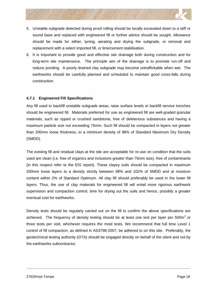
The use of excavators with hydraulic impact hammer attachments, albeit small and lightweight, for
any shale excavation should be approached with considerable caution, as there will likely be
direct transmission of ground vibrations to nearby structures and buildings. Guideline levels of
vibration velocity for evaluating the effects of vibration in structures are given in the attached
Vibration Emission Design Goals sheet. We recommend that the acceptable limit for transmitted
vibrations be set at quite a low peak particle velocity of 5mm/s for frequencies of less than 10Hz
at foundation level. If it is found that transmitted vibrations are unacceptable, then it may then be
necessary to change to a smaller excavator with a smaller rock hammer, or to a rotary rock
grinder, rock saws, or jackhammers.
If rock hammers are to be used, we recommend that the initial excavation in rock should
preferably be commenced away from likely critical areas and instrument vibration monitoring
undertaken. The monitoring program should be confirmed when details of the contractor’s
excavation methods and sequence are known. By monitoring vibrations in this way, it will allow
some freedom to the excavation contractor in the equipment he adopts, so that a balance can be
made between productivity and vibration reduction.

27926Vrpt-Tempe Page 11
Vibrations induced by excavations can be reduced by alternative methods such as the following:
Start the rock excavation away from likely critical areas.
Maintain rock hammer orientation into the face and enlarge excavation by breaking small
wedges off faces.
Operate hammers in short bursts only, to prevent amplification of vibrations.
Use smaller equipment (offset by a loss in productivity and economy and greater duration of
the nuisance).
Use line sawing, especially along boundaries, to aid breaking and trimming.
In addition, we recommend that only excavation contractors with appropriate insurances and
experience on similar projects be used. The contractor should also be provided with a copy of
this report to make his own judgement on the most appropriate excavation equipment.
4.4 Groundwater Considerations and Drainage
The groundwater levels vary significantly at the site. Most boreholes did not encounter
groundwater seepage during and on completion of drilling. The seepage appears to be slow,
which is not surprising in view of the very low permeability clays and shale, since it took some
time to materialize into a water level in the boreholes that had standpipe wells installed (BHs 1, 4
and 9). Furthermore, it is known from measurements in BH1 standpipe that the water level took 3
days to rise over a height of 1.7m.
Hence, we assess that groundwater seepage into the excavation is unlikely to be a significant
issue for the proposed basement, since seepage appears to be slow and water levels were quite
deep in standpipe BH4 (RL12.8m) and BH9 (RL7.9m); only standpipe BH1 had a shallower water
level at RL13.9m. We suspect that the water levels recorded in the borehole standpipes do not
represent a ‘true’ groundwater table, but rather indicate that seepage occurs through defects in
the rock mass and probably along the soil bedrock interface, and these seepage flows collect in
the borehole standpipes to the levels indicated. This should be confirmed by completing pump out
tests that show diminution of seepage rate with time.
In general terms, any retaining structures around the perimeter of the basement must incorporate
permanent drainage provisions and perimeter spoon drains around the basement will be required
to collect seepage flows and direct them to appropriate pumping sumps. Such water could be
used for irrigation around the site depending on the results of the groundwater assessment by
EIS: refer to their report. Some drainage will be required below the basement floor slabs and this
may take the form of discrete drains on a grid pattern or a drainage blanket of single sized 'blue
27926Vrpt-Tempe Page 12
metal' gravel. A fail safe automatic pump-out system may have to be adopted to reduce the
likelihood of flooding of the basement. However, based on the low permeability subsurface
profile, we are of the opinion that seepage volumes into the basement would be of a relatively low
order. We recommend that under-floor drainage or uplift resistance requirements be reviewed
following pump out testing in existing wells and inspection of the completed excavation when
such issues can be more readily considered.
We do not anticipate that drainage of such flows would have a significant effect on properties in
the surrounding area and that the volumes which would be pumped from the basement are
assumed at this preliminary stage to be quite minor. The completed excavation should be
inspected by the geotechnical and hydraulic engineers shortly after completion, in order to
confirm that these assumed groundwater conditions are realistic and to identify any particular
seepage flows, which require drainage measures.
4.5 Retention and Batter Slopes
The basement excavation will require full support by shoring pile walls, which is our preferred
method of support, due to the low or lesser strengths layers in the shale profile encountered in a
number of boreholes; this can be reviewed once we have completed more detailed investigation
using rock cored boreholes (refer to Section 4.1.1). Properly designed in situ shoring pile systems
may be incorporated into the permanent basement retention system. We recommend that the
support system either be anchored or propped.
An anchored contiguous pile will be required to limit wall movement along critical or movement
sensitive sides of the excavation. An anchored soldier pile wall with shotcrete infill panels should
generally be suitable along boundaries given where there are no buildings within close proximity
of the excavation and assuming some wall movement is acceptable.
Temporary anchors to support shoring piles should be bonded into shale of at least low to
medium strength. Where anchors extend beyond the property boundaries, it will be necessary to
obtain permission from the owners of the adjacent properties prior to their installation. Careful
checks must be made of any adjoining buildings, which might have basement structures that may
interfere with anchor installations.
Bored pier or CFA (augered grout injected) piles may be used for the shoring walls. Piles should
be socketed for an appropriate design depth to maintain wall stability, preferably below the base
of the excavation, including below local footing and service excavations. We recommend large

27926Vrpt-Tempe Page 13
and high capacity drilling rigs with rock drilling equipment be used to drill the piles. The proposed
piling contractor must, therefore, be given a copy of the final detailed geotechnical investigation
report to ensure that appropriate equipment with sufficient power is brought to site. Piles should
be poured immediately or at the very latest, on the same day, as drilling, cleaning and inspection.
Special tools should be used to roughen the sides of load bearing pile sockets in the shale.
Water should be removed from the base of bored piles prior to concreting or the concrete placed
using tremie methods.
Another support alternative is to cut the excavation sides at stable shallow angle batter slopes, if
there is room or space within the site to accommodate these slopes. Our recommended
temporary batters would be no steeper than 1 Horizontal (H) to 1 Vertical (V) in soils and shale of
low or lesser strengths.
However, surcharge loadings (footings, vehicles, etc) should not be within the zone of influence of
the excavation. As a guide, surcharge loadings should be no closer than 2H from the top of any
batter or the face of any excavation (including footing excavations), where H is the vertical height
of the batter or depth of the excavation. Flatter batters may be required where groundwater
seepage is encountered. The stability of the batters in the shale must be subject to confirmation
by an inspection by a geotechnical engineer as the excavation progresses and the batters are
formed say in intervals of 1.5m depth.
During construction, the excavation should be inspected by a geotechnical engineer at vertical
intervals not exceeding 1.5m in order that any inclined defects (e.g. very steep joints) or other
adverse conditions can be identified and, if necessary, stabilisation measures implemented. The
most likely stabilisation measures which may be required would involve rock bolting with bolt
lengths ranging from 3m to 5m being most probable. A provision for rock bolting and shotcrete
and mesh should be included in the Contract Documents for works nominated following the
geotechnical inspections. If extensive weathered seams are found, it may be necessary to
provide temporary as well as permanent support in order to maintain safe working conditions; the
use of shotcrete together with mesh and rock dowels are the most common means of providing
this type of support. In the long term, some treatment of seams or fractured zones may also be
necessary and such support may be provided either by means of retaining walls propped from the
permanent structure or, in this case, by means of permanent rock bolts which can be
accommodated within the site boundaries. Of course permanent rock bolts would require
appropriate detailing for long term corrosion protection. Design lateral pressures for support of

27926Vrpt-Tempe Page 14
weathered and fractured zones by structural means would be determined once the problems
could be assessed in the excavation.
During the excavation, every care should be taken to not undermine or render unstable the
footings of any adjoining structure. The effect of ground movements on any buildings and
services that lie within the influence zone of the excavation must also be taken into account. No
matter what method of excavation and support system is used, some ground displacement will
occur both within and immediately surrounding the bulk excavation. The final deformations of the
excavation support systems, which are recommended in this report, are highly dependent on the
construction sequence and detailing. The magnitude of lateral movement is also directly related to
the stiffness of the retaining system. The risks of architectural and/or structural damage to the
neighbouring buildings will depend on their sensitivity to horizontal and vertical deformations
(induced by the proposed excavation), structural loading, type and founding levels of footings and
foundation conditions. All these factors must be carefully investigated and evaluated prior to
excavation commencing.
4.5.1 Lateral Pressures
For design of anchored or propped walls, we recommend the use of a trapezoidal lateral pressure
distribution with at least magnitude of 4H kPa (where H is the total depth in metres of the residual
clay and upper extremely low (EL) to low (L) strength shale, which may be reduced down to 2H
over the shale of at least low (L) to medium (M) strength or greater strengths. The full lateral
pressure is applicable over the central 50% of the trapezoidal pressure distribution. For areas that
are highly sensitive to lateral movement, consideration should be given to using a trapezoidal
lateral pressure distribution of magnitude 8H kPa and 4H kPa, over the aforementioned materials
respectively, or greater, to limit deflections.
All appropriate hydrostatic pressures and surcharge loads should be incorporated in the design of
the retaining walls. Design surcharge loads on the shoring should take account of existing façade
loads, any traffic loads, heavy crane loads, hoarding loads and vehicle impact on hoarding
structure. We recommend that only the services of a proven and competent earthworks and
shoring contractor be considered. The above lateral pressures and coefficients assume horizontal
backfill surfaces and where inclined backfill is proposed the pressures or coefficients would need
to be increased or the inclined backfill taken as a surcharge load.

27926Vrpt-Tempe Page 15
For the design of walls socketed into the shale of at least low to medium strength, it is
recommended that a maximum allowable toe resistance of 250kPa may be used below the base
of the excavation, including footing and service excavations, to resist the lateral pressure.
Anchors should have their anchor bond length within shale of at least low strength. For the
design of anchors bonded into such strength rock an allowable bond stress of 200kPa is
recommended subject to the following conditions:
Anchor bond length of at least 3m behind the ‘active’ zone of the excavation.
Overall stability, including anchor group interaction, is satisfied.
All anchors are respectively proof loaded to at least 1.3 times the design working load before
locking off at working load.
Higher bond stresses may be justified if the results from a testing program on prototype anchors
indicate this to be appropriate.
4.6 Foundation Strata
Following bulk excavations, shale is expected to be exposed over the lowest basement level or to
be close to the finished floor level, depending on the final basement levels adopted. It is
recommended that all footings for the building and retaining walls be founded within the shale of
relatively similar competency to provide uniform support and reduce the potential for differential
footing settlements.
The footing systems will require careful consideration due to the variable shale conditions. A
mixture of footing types is expected to be required to reach the desired shale strength. Pad or
strip or piled footings may be designed using the following maximum allowable bearing pressure
(ABP); higher bearing pressures (e.g. 3500kPa) might be probable subject to proving and
confirmation by the additional deep cored boreholes:
1. Shale of Extremely Low (EL) Strength: ABP of 700kPa;
2. Shale of Very Low (VL) Strengths: ABP of 1000kPa;
3. Shale of Low (L) or greater Strengths: ABP of 1500kPa;
During construction inspections the geotechnical engineer should nominate any additional testing
if necessary. The presence of significant defects or lower strength bedrock would require a
reduction in allowable bearing capacity or an increase in footing depth.

27926Vrpt-Tempe Page 16
An allowable shaft adhesion (ASA) of equivalent to 10% of the above ABP values may be
adopted for design of pile sockets in compression through the shale. For uplift or tension, the
ASA value should be halved. We expect that deep or long sockets into shale of medium or
greater strength would be slow and difficult to drill and it would be advisable to avoid these
wherever possible.
All footing excavations should be free from all loose or softened materials prior to placement of
concrete. We recommend that footing excavations be checked and approved prior to concrete
being poured. The initial stages of footing excavation should be inspected by a geotechnical
engineer to ascertain that the recommended foundation has been reached and to check initial
assumptions about foundation conditions and possible variations that may occur between
borehole locations. The need for further inspections can be assessed following the initial visit.
We can assist with future geotechnical inspections if you wish to commission us at the
appropriate time.
During installation of piles it is recommended that the initial piles be installed as close as practical
to our borehole locations to calibrate the equipment and operator to the subsurface conditions by
direction comparison of the installation performance and readings to the borehole results. These
initial readings can then be used to assist with installation of piles away from the borehole
locations to assess that the appropriate foundation material has been reached. Bored or CFA
(augered grout injected) piles may be used. We recommend large capacity drilling rigs with rock
drilling equipment be used to drill the piles. The proposed piling contractor must, therefore, be
given a copy of the final detailed geotechnical investigation report to ensure that appropriate
equipment with sufficient power is brought to site. Piles should be poured immediately or at the
very latest, on the same day, as drilling, cleaning and inspection. Special tools should be used to
roughen the sides of load bearing pile sockets in the shale. Water should be removed from the
base of bored piles prior to concreting or the concrete placed using tremie methods.
The site has been altered by fill and hence, is classified as Class 'P' in accordance with AS2870-
2011. We note that the underlying residual clays are considered to be moderately reactive
equivalent to Class M. Although the behaviour of reactive clays and its effects on a building or
other movement sensitive structures is very complex, the prediction of ground movements may be
undertaken in accordance with the method suggested in AS2870-2011 “Residential Slabs and
Footings – Construction”. We advice that in the strict sense AS2870 site classification does not
27926Vrpt-Tempe Page 17
apply to this size structure but it is a useful guide in highlighting the potential foundation problems
of the soils of this site.
4.7 Other Earthworks
The main geotechnical issues with other earthworks, including subgrade preparation, under floor
slab (and external pavement areas) are to do with any existing fill that may remain after
excavation for the proposed car parking basement levels. The existing fill appears to be variably
compacted. The fill is deemed unsuitable as a bearing stratum for warehouse footings and floor
slabs. In the building and slab footprint areas most of the fill is expected to be removed by the
proposed graded excavations. However, where it is seen to be remaining then it should be
excavated and replaced with engineered fill that can then support the slab on grade; all footings
must be founded on the shale bedrock. The fill is also considered a ‘moderate to high risk’ (of
poor performance) as a supporting subgrade under external pavements. Again, we prefer that the
fill be removed and replaced with engineered fill.
Earthworks recommendations provided in this report should be complemented by reference to
AS3798. In summary, we recommend that:
1. After reaching the bulk excavation level for the basement car parking levels (unknown at the
time of this Due Diligence investigation), excavate further any remaining fill down to surface of
the residual clay. The backfilling should then proceed with engineered, controlled fill. The
replacement should extend to at least 2m beyond the boundaries of the floor/pavement area.
Such an excavation if deeper than 1.2m would have to be completed with battered sides of
not steeper than 1 Vertical to 1.5 Horizontal. The earthworks contractor must ensure that
during the backfilling earthworks that the engineered fill is well ‘keyed’ into the side batters of
the excavation.
2. The exposed subgrade at the base of the excavation should be proof rolled with at least 8
passes of a heavy (not less than 12 tonne) smooth drum vibratory roller. The purpose of the
proof rolling is to detect any soft or heaving areas. Caution is required when proof rolling near
any neighbouring improvements and buried services.
3. The final pass should be undertaken in the presence of a geotechnician or geotechnical
engineer, to detect any unstable or soft subgrade areas, and to allow for some further
improvement in strength/compaction.
4. If dry conditions prevail at the time of construction then any exposed residual clay subgrade
may become desiccated or have shrinkage cracks prior to pouring any concrete slabs. If this
occurs then the subgrade must be watered and rolled until the cracks disappear.
27926Vrpt-Tempe Page 18
5. Unstable subgrade detected during proof rolling should be locally excavated down to a stiff or
sound base and replaced with engineered fill or further advice should be sought. Allowance
should be made for either, tyning, aerating and drying the subgrade, or removal and
replacement with a select imported fill, or lime/cement stabilisation.
6. It is important to provide good and effective site drainage both during construction and for
long-term site maintenance. The principle aim of the drainage is to promote run-off and
reduce ponding. A poorly drained clay subgrade may become untraffickable when wet. The
earthworks should be carefully planned and scheduled to maintain good cross-falls during
construction.
4.7.1 Engineered Fill Specifications
Any fill used to backfill unstable subgrade areas, raise surface levels or backfill service trenches
should be engineered fill. Materials preferred for use as engineered fill are well-graded granular
materials, such as ripped or crushed sandstone, free of deleterious substances and having a
maximum particle size not exceeding 75mm. Such fill should be compacted in layers not greater
than 200mm loose thickness, to a minimum density of 98% of Standard Maximum Dry Density
(SMDD).
The existing fill and residual clays at the site are acceptable for re-use on condition that the soils
used are clean (i.e. free of organics and inclusions greater than 75mm size), free of contaminants
(in this respect refer to the EIS report). These clayey soils should be compacted in maximum
200mm loose layers to a density strictly between 98% and 102% of SMDD and at moisture
content within 2% of Standard Optimum. All clay fill should preferably be used in the lower fill
layers. Thus, the use of clay materials for engineered fill will entail more rigorous earthwork
supervision and compaction control, time for drying out the soils and hence, possibly a greater
eventual cost for earthworks.
Density tests should be regularly carried out on the fill to confirm the above specifications are
achieved. The frequency of density testing should be at least one test per layer per 500m2 or
three tests per visit, whichever requires the most tests. We recommend that full time Level 1
control of fill compaction, as defined in AS3798-2007, be adhered to on this site. Preferably, the
geotechnical testing authority (GTA) should be engaged directly on behalf of the client and not by
the earthworks subcontractor.

27926Vrpt-Tempe Page 19
During construction of the fill platform runoff should be enhanced by providing suitable falls to
reduce ponding of water on the surface of the fill. Ponding of water may lead to softening of the
fill and subsequent delays in the earthworks program.
4.8 Pavement Design
The design of new pavements will depend on subgrade preparation, subgrade drainage, the
nature and composition of fill excavated or imported to the site, as well as vehicle loadings and
use. Refer to Section 4.7 on subgrade preparation and other earthwork procedures including
engineered fill specifications and compaction control.
Various alternative types of construction could be used for the pavements. Concrete construction
would undoubtedly be the best in areas where heavy vehicles manoeuvre such as truck turning
and manoeuvring. Flexible pavements may have a lower initial cost but maintenance will be
higher. These factors should be considered when making the final choice.
The residual clay subgrade has a low soaked CBR value. We recommend that the pavement
thickness design should be based on the CBR of 3%.
Further soaked CBR tests may be carried out on representative samples of the subgrade. If the
existing fill is removed and replaced with imported fill, the CBR of the imported material may be
taken into account. These design values should be confirmed by inspection and DCP testing of
the subgrade following proof rolling.
All upper (base) course are recommended to be crushed rock to RTA QA specification 3051
(1994) unbound base and compacted to at least 100% of Standard Maximum Dry Density. All
lower (sub-base) course are recommended to be crushed rock to RTA QA specification 3051
(1994) unbound base or ripped/crushed sandstone with CBR greater than 40%, maximum particle
size of 60mm, well graded and Plastic Index less than 10. All lower course material should be
compacted to an average of no less than 100% of SMDD, but with a minimum acceptance value
of 98% of SMDD.
Concrete pavements are recommended to have a sub-base layer of at least 100mm thickness of
crushed rock to RTA QA specification 3051 (1994) unbound base material (or equivalent good
quality and durable fine crushed rock) which is compacted to at least 100% SMDD. Concrete
pavements should be designed with an effective shear transmission of all joints by way of either
doweled or keyed joints.

27926Vrpt-Tempe Page 20
Careful attention to subsurface and surface drainage is required in view of the effect of moisture
on the clay soils. Pavement levels will need to be graded to promote rapid removal of surface
water so ponding does not occur on the surface of pavements.
5 GENERAL COMMENTS
The preliminary recommendations presented in this report include specific issues to be addressed
during the DA, CC and construction phases of the project. In the event that any of the phase
recommendations presented in this report are not implemented, the general recommendations
may become inapplicable and JK Geotechnics accept no responsibility whatsoever for the
performance of the structure where recommendations are not implemented in full and properly
tested, inspected and documented.
The long term successful performance of floor slabs and pavements is dependent on the
satisfactory completion of the earthworks. In order to achieve this, the quality assurance program
should not be limited to routine compaction density testing only. Other critical factors associated
with the earthworks may include subgrade preparation, selection of fill materials, control of
moisture content and drainage, etc. The satisfactory control and assessment of these items may
require judgment from an experienced engineer. Such judgment often cannot be made by a
technician who may not have formal engineering qualifications and experience. In order to
identify potential problems, we recommend that a pre-construction meeting be held so that all
parties involved understand the earthworks requirements and potential difficulties. This meeting
should clearly define the lines of communication and responsibility.
Occasionally, the subsurface conditions between the completed boreholes may be found to be
different (or may be interpreted to be different) from those expected. Variation can also occur
with groundwater conditions, especially after climatic changes. If such differences appear to
exist, we recommend that you immediately contact this office.
This report provides preliminary advice on geotechnical aspects for the proposed civil and
structural design. As part of the documentation stage of this project, Draft Contract Documents
and Specifications may be prepared based on our report. However, there may be design features
we are not aware of or have not commented on for a variety of reasons. The designers should
satisfy themselves that all the necessary advice has been obtained. If required, we could be

27926Vrpt-Tempe Page 21
commissioned to review the geotechnical aspects of contract documents to confirm the intent of
our recommendations has been correctly implemented.
This report has been prepared for the particular project described and no responsibility is
accepted for the use of any part of this report in any other context or for any other purpose.
If there is any change in the proposed development described in this report then all
recommendations should be reviewed. Copyright in this report is the property of JK Geotechnics.
We have used a degree of care, skill and diligence normally exercised by consulting engineers in
similar circumstances and locality. No other warranty expressed or implied is made or intended.
Subject to payment of all fees due for the investigation, the client alone shall have a licence to
use this report. The report shall not be reproduced except in full.


JKG Vibrat
Germanevaluatrecogni
The DINlevels msumma
It shoulfrequenconditio
It shouleffects include enlargeload beit may b‘safe lima broad
Table 1
Group
1
2
3
Note: F
GEOTEC
tion Emission Des
n Standard ing the effesed to be co
N 4150 valumeasured i
arised in Tab
d be noted ncies may beon of the stru
ld also be nhas been oeven mino
ement of craearing walls.be attributedmits’ are pred guide.
1: DIN 4150
Type of S
Buildings upurposes, and buildin
Dwellings similar des
Structuresparticular do not corin Group 1intrinsic vaare under
For frequenci
HNICAL & ENVI
sign Goals Rev1 J
VI
DIN 4150 cts of vibratonservative.
ues (maximun (x) or (y
ble 1 below.
that peak ve quite ‘safeucture.
noted that thobserved foror non-strucacks already Should dam
d to other caesent, it does
– Structura
Structure
used for commindustrial buil
ngs of similar
and buildingssign and/or us
s that becausesensitivity to vrrespond to tho1 and 2 and haalue (eg. builda preservatio
es above 10
RONMENTAL E
July12
BRATION E
– Part 3: tion in struc
um levels my) horizonta
vibration veloe’, dependin
hese levels r the particuctural effecty present, amage be obauses. DIN 4s not necess
al Damage –
mercial ldings design.
of se.
e of their vibration, ose listed ave ings that n order).
0Hz, the hig
NGINEERS
EMISSION
1986 providctures. The l
easured in aal directions
ocities higheng on the fre
are ‘safe limlar class of ts such asnd the sepa
bserved at vi4150 also stsarily follow
– Safe Limi
Less than 10Hz
20
5
3
her values in
Jeffery & Katausk
DESIGN G
des guidelinlimits prese
any directio, in the pla
er than the mequency con
mits’, up to wbuilding. ‘D
s superficialaration of paibration levetates that wh that damag
its for Build
Peak Vib
At Foundatiat a Freque
10Hz 50Hz
20 to 4
5 to 1
3 to 8
n the 50Hz to
kas Pty Ltd, tradin
OALS
ne levels onted in this
n at the fouane of the
minimum figntent of the v
which no daDamage’ is d
cracking iartitions or iels lower thahen vibrationge will occur
ding Vibrati
bration Veloc
on Level ency of:
to z
5
40 4
5 1
8 8
o 100Hz colu
ng as JK Geotech
of vibration standard ar
ndation, ORuppermost
gures in Tabvibration an
amage due defined by Din cement intermediatean the ‘safe n levels highr. Values giv
ion
city in mm/s
50Hz to 100Hz
40 to 50
15 to 20
8 to 10
umn should b
nics ABN 17 003
Pag
velocity forre generally
R, maximumt floor), are
ble 1 for lowd the actual
to vibrationDIN 4150 torender, the
e walls fromlimits’, then
her than theven are only
Plane of Floof Uppermo
Storey
All Frequenc
40
15
8
be used.
550 801
ge 1 of 1
r y
m e
w l
n o e m n e y
oor ost
cies

Jeffery & Katauskas Pty Ltd, trading as JK Geotechnics ABN 17 003 550 801
JKG Report Explanation Notes Rev2 May 2013 Page 1 of 4
REPORT EXPLANATION NOTES
INTRODUCTION
These notes have been provided to amplify the geotechnicalreport in regard to classification methods, field proceduresand certain matters relating to the Comments andRecommendations section. Not all notes are necessarilyrelevant to all reports.
The ground is a product of continuing natural and man-made processes and therefore exhibits a variety ofcharacteristics and properties which vary from place to placeand can change with time. Geotechnical engineeringinvolves gathering and assimilating limited facts about thesecharacteristics and properties in order to understand orpredict the behaviour of the ground on a particular site undercertain conditions. This report may contain such factsobtained by inspection, excavation, probing, sampling,testing or other means of investigation. If so, they aredirectly relevant only to the ground at the place where andtime when the investigation was carried out.
DESCRIPTION AND CLASSIFICATION METHODS
The methods of description and classification of soils androcks used in this report are based on Australian Standard1726, the SAA Site Investigation Code. In general,descriptions cover the following properties – soil or rock type,colour, structure, strength or density, and inclusions.Identification and classification of soil and rock involvesjudgement and the Company infers accuracy only to theextent that is common in current geotechnical practice.
Soil types are described according to the predominatingparticle size and behaviour as set out in the attached UnifiedSoil Classification Table qualified by the grading of otherparticles present (e.g. sandy clay) as set out below:
Soil Classification Particle Size
Clay
Silt
Sand
Gravel
less than 0.002mm
0.002 to 0.075mm
0.075 to 2mm
2 to 60mm
Non-cohesive soils are classified on the basis of relativedensity, generally from the results of Standard PenetrationTest (SPT) as below:
Relative DensitySPT ‘N’ Value(blows/300mm)
Very loose
Loose
Medium dense
Dense
Very Dense
less than 4
4 – 10
10 – 30
30 – 50
greater than 50
Cohesive soils are classified on the basis of strength(consistency) either by use of hand penetrometer, laboratorytesting or engineering examination. The strength terms aredefined as follows.
ClassificationUnconfined CompressiveStrength kPa
Very Soft
Soft
Firm
Stiff
Very Stiff
Hard
Friable
less than 25
25 – 50
50 – 100
100 – 200
200 – 400
Greater than 400
Strength not attainable
– soil crumbles
Rock types are classified by their geological names,together with descriptive terms regarding weathering,strength, defects, etc. Where relevant, further informationregarding rock classification is given in the text of the report.In the Sydney Basin, ‘Shale’ is used to describe thinlybedded to laminated siltstone.
SAMPLING
Sampling is carried out during drilling or from otherexcavations to allow engineering examination (andlaboratory testing where required) of the soil or rock.
Disturbed samples taken during drilling provide informationon plasticity, grain size, colour, moisture content, minorconstituents and, depending upon the degree of disturbance,some information on strength and structure. Bulk samplesare similar but of greater volume required for some testprocedures.
Undisturbed samples are taken by pushing a thin-walledsample tube, usually 50mm diameter (known as a U50), intothe soil and withdrawing it with a sample of the soilcontained in a relatively undisturbed state. Such samplesyield information on structure and strength, and arenecessary for laboratory determination of shear strengthand compressibility. Undisturbed sampling is generallyeffective only in cohesive soils.
Details of the type and method of sampling used are givenon the attached logs.
INVESTIGATION METHODS
The following is a brief summary of investigation methodscurrently adopted by the Company and some comments ontheir use and application. All except test pits, hand augerdrilling and portable dynamic cone penetrometers requirethe use of a mechanical drilling rig which is commonlymounted on a truck chassis.
JK GeotechnicsGEOTECHNICAL & ENVIRONMENTAL ENGINEERS

JKG Report Explanation Notes Rev2 May 2013 Page 2 of 4
Test Pits: These are normally excavated with a backhoe or
a tracked excavator, allowing close examination of the insitusoils if it is safe to descend into the pit. The depth ofpenetration is limited to about 3m for a backhoe and up to6m for an excavator. Limitations of test pits are the problemsassociated with disturbance and difficulty of reinstatementand the consequent effects on close-by structures. Caremust be taken if construction is to be carried out near test pitlocations to either properly recompact the backfill duringconstruction or to design and construct the structure so asnot to be adversely affected by poorly compacted backfill atthe test pit location.
Hand Auger Drilling: A borehole of 50mm to 100mm
diameter is advanced by manually operated equipment.Premature refusal of the hand augers can occur on a varietyof materials such as hard clay, gravel or ironstone, and doesnot necessarily indicate rock level.
Continuous Spiral Flight Augers: The borehole is
advanced using 75mm to 115mm diameter continuousspiral flight augers, which are withdrawn at intervals to allowsampling and insitu testing. This is a relatively economicalmeans of drilling in clays and in sands above the water table.Samples are returned to the surface by the flights or may becollected after withdrawal of the auger flights, but they canbe very disturbed and layers may become mixed.Information from the auger sampling (as distinct fromspecific sampling by SPTs or undisturbed samples) is ofrelatively lower reliability due to mixing or softening ofsamples by groundwater, or uncertainties as to the originaldepth of the samples. Augering below the groundwatertable is of even lesser reliability than augering above thewater table.
Rock Augering: Use can be made of a Tungsten Carbide
(TC) bit for auger drilling into rock to indicate rock qualityand continuity by variation in drilling resistance and fromexamination of recovered rock fragments. This method ofinvestigation is quick and relatively inexpensive but providesonly an indication of the likely rock strength and predictedvalues may be in error by a strength order. Where rockstrengths may have a significant impact on constructionfeasibility or costs, then further investigation by means ofcored boreholes may be warranted.
Wash Boring: The borehole is usually advanced by a
rotary bit, with water being pumped down the drill rods andreturned up the annulus, carrying the drill cuttings.Only major changes in stratification can be determined fromthe cuttings, together with some information from “feel” andrate of penetration.
Mud Stabilised Drilling: Either Wash Boring or
Continuous Core Drilling can use drilling mud as acirculating fluid to stabilise the borehole. The term ‘mud’encompasses a range of products ranging from bentonite topolymers such as Revert or Biogel. The mud tends to maskthe cuttings and reliable identification is only possible fromintermittent intact sampling (eg from SPT and U50 samples)or from rock coring, etc.
Continuous Core Drilling: A continuous core sample is
obtained using a diamond tipped core barrel. Provided fullcore recovery is achieved (which is not always possible invery low strength rocks and granular soils), this techniqueprovides a very reliable (but relatively expensive) method ofinvestigation. In rocks, an NMLC triple tube core barrel,which gives a core of about 50mm diameter, is usually usedwith water flush. The length of core recovered is comparedto the length drilled and any length not recovered is shownas CORE LOSS. The location of losses are determined onsite by the supervising engineer; where the location isuncertain, the loss is placed at the top end of the drill run.
Standard Penetration Tests: Standard Penetration Tests
(SPT) are used mainly in non-cohesive soils, but can alsobe used in cohesive soils as a means of indicating density orstrength and also of obtaining a relatively undisturbedsample. The test procedure is described in AustralianStandard 1289, “Methods of Testing Soils for EngineeringPurposes” – Test F3.1.
The test is carried out in a borehole by driving a 50mmdiameter split sample tube with a tapered shoe, under theimpact of a 63kg hammer with a free fall of 760mm. It isnormal for the tube to be driven in three successive 150mmincrements and the ‘N’ value is taken as the number ofblows for the last 300mm. In dense sands, very hard claysor weak rock, the full 450mm penetration may not bepracticable and the test is discontinued.
The test results are reported in the following form:
In the case where full penetration is obtained withsuccessive blow counts for each 150mm of, say, 4, 6and 7 blows, as
N = 134, 6, 7
In a case where the test is discontinued short of fullpenetration, say after 15 blows for the first 150mm and30 blows for the next 40mm, as
N>3015, 30/40mm
The results of the test can be related empirically to theengineering properties of the soil.
Occasionally, the drop hammer is used to drive 50mmdiameter thin walled sample tubes (U50) in clays. In suchcircumstances, the test results are shown on the boreholelogs in brackets.
A modification to the SPT test is where the same driving
system is used with a solid 60 tipped steel cone of thesame diameter as the SPT hollow sampler. The solid conecan be continuously driven for some distance in soft clays orloose sands, or may be used where damage wouldotherwise occur to the SPT. The results of this Solid ConePenetration Test (SCPT) are shown as "N c” on the boreholelogs, together with the number of blows per 150mmpenetration.

JKG Report Explanation Notes Rev2 May 2013 Page 3 of 4
Static Cone Penetrometer Testing and Interpretation:
Cone penetrometer testing (sometimes referred to as aDutch Cone) described in this report has been carried outusing an Electronic Friction Cone Penetrometer (EFCP).The test is described in Australian Standard 1289, Test F5.1.
In the tests, a 35mm diameter rod with a conical tip ispushed continuously into the soil, the reaction beingprovided by a specially designed truck or rig which is fittedwith an hydraulic ram system. Measurements are made ofthe end bearing resistance on the cone and the frictionalresistance on a separate 134mm long sleeve, immediatelybehind the cone. Transducers in the tip of the assembly areelectrically connected by wires passing through the centre ofthe push rods to an amplifier and recorder unit mounted onthe control truck.
As penetration occurs (at a rate of approximately 20mm persecond) the information is output as incremental digitalrecords every 10mm. The results given in this report havebeen plotted from the digital data.
The information provided on the charts comprise:
Cone resistance – the actual end bearing force dividedby the cross sectional area of the cone – expressed inMPa.
Sleeve friction – the frictional force on the sleeve dividedby the surface area – expressed in kPa.
Friction ratio – the ratio of sleeve friction to coneresistance, expressed as a percentage.
The ratios of the sleeve resistance to cone resistancewill vary with the type of soil encountered, with higherrelative friction in clays than in sands. Friction ratios of1% to 2% are commonly encountered in sands andoccasionally very soft clays, rising to 4% to 10% in stiffclays and peats. Soil descriptions based on coneresistance and friction ratios are only inferred and mustnot be considered as exact.
Correlations between EFCP and SPT values can bedeveloped for both sands and clays but may be site specific.
Interpretation of EFCP values can be made to empiricallyderive modulus or compressibility values to allow calculationof foundation settlements.
Stratification can be inferred from the cone and frictiontraces and from experience and information from nearbyboreholes etc. Where shown, this information is presentedfor general guidance, but must be regarded as interpretive.The test method provides a continuous profile ofengineering properties but, where precise information on soilclassification is required, direct drilling and sampling may bepreferable.
Portable Dynamic Cone Penetrometers: Portable
Dynamic Cone Penetrometer (DCP) tests are carried out bydriving a rod into the ground with a sliding hammer andcounting the blows for successive 100mm increments ofpenetration.
Two relatively similar tests are used:
Cone penetrometer (commonly known as the ScalaPenetrometer) – a 16mm rod with a 20mm diametercone end is driven with a 9kg hammer dropping 510mm(AS1289, Test F3.2). The test was developed initiallyfor pavement subgrade investigations, and correlationsof the test results with California Bearing Ratio havebeen published by various Road Authorities.
Perth sand penetrometer – a 16mm diameter flat endedrod is driven with a 9kg hammer, dropping 600mm(AS1289, Test F3.3). This test was developed fortesting the density of sands (originating in Perth) and ismainly used in granular soils and filling.
LOGS
The borehole or test pit logs presented herein are anengineering and/or geological interpretation of the sub-surface conditions, and their reliability will depend to someextent on the frequency of sampling and the method ofdrilling or excavation. Ideally, continuous undisturbedsampling or core drilling will enable the most reliableassessment, but is not always practicable or possible tojustify on economic grounds. In any case, the boreholes ortest pits represent only a very small sample of the totalsubsurface conditions.
The attached explanatory notes define the terms andsymbols used in preparation of the logs.
Interpretation of the information shown on the logs, and itsapplication to design and construction, should therefore takeinto account the spacing of boreholes or test pits, themethod of drilling or excavation, the frequency of samplingand testing and the possibility of other than “straight line”variations between the boreholes or test pits. Subsurfaceconditions between boreholes or test pits may varysignificantly from conditions encountered at the borehole ortest pit locations.
GROUNDWATER
Where groundwater levels are measured in boreholes, thereare several potential problems:
Although groundwater may be present, in lowpermeability soils it may enter the hole slowly or perhapsnot at all during the time it is left open.
A localised perched water table may lead to anerroneous indication of the true water table.
Water table levels will vary from time to time withseasons or recent weather changes and may not be thesame at the time of construction.
The use of water or mud as a drilling fluid will mask anygroundwater inflow. Water has to be blown out of thehole and drilling mud must be washed out of the hole or‘reverted’ chemically if water observations are to bemade.
JKG Report Explanation Notes Rev2 May 2013 Page 4 of 4
More reliable measurements can be made by installingstandpipes which are read after stabilising at intervalsranging from several days to perhaps weeks for lowpermeability soils. Piezometers, sealed in a particularstratum, may be advisable in low permeability soils or wherethere may be interference from perched water tables orsurface water.
FILL
The presence of fill materials can often be determined onlyby the inclusion of foreign objects (eg bricks, steel etc) or bydistinctly unusual colour, texture or fabric. Identification ofthe extent of fill materials will also depend on investigationmethods and frequency. Where natural soils similar tothose at the site are used for fill, it may be difficult withlimited testing and sampling to reliably determine the extentof the fill.
The presence of fill materials is usually regarded withcaution as the possible variation in density, strength andmaterial type is much greater than with natural soil deposits.Consequently, there is an increased risk of adverseengineering characteristics or behaviour. If the volume andquality of fill is of importance to a project, then frequent testpit excavations are preferable to boreholes.
LABORATORY TESTING
Laboratory testing is normally carried out in accordance withAustralian Standard 1289 ‘Methods of Testing Soil forEngineering Purposes’. Details of the test procedure usedare given on the individual report forms.
ENGINEERING REPORTS
Engineering reports are prepared by qualified personnel andare based on the information obtained and on currentengineering standards of interpretation and analysis. Wherethe report has been prepared for a specific design proposal(eg. a three storey building) the information andinterpretation may not be relevant if the design proposal ischanged (eg to a twenty storey building). If this happens,the company will be pleased to review the report and thesufficiency of the investigation work.
Every care is taken with the report as it relates tointerpretation of subsurface conditions, discussion ofgeotechnical aspects and recommendations or suggestionsfor design and construction. However, the Company cannotalways anticipate or assume responsibility for:
Unexpected variations in ground conditions – thepotential for this will be partially dependent on boreholespacing and sampling frequency as well as investigationtechnique.
Changes in policy or interpretation of policy by statutoryauthorities.
The actions of persons or contractors responding tocommercial pressures.
If these occur, the company will be pleased to assist withinvestigation or advice to resolve any problems occurring.
SITE ANOMALIES
In the event that conditions encountered on site duringconstruction appear to vary from those which were expectedfrom the information contained in the report, the companyrequests that it immediately be notified. Most problems aremuch more readily resolved when conditions are exposedthat at some later stage, well after the event.
REPRODUCTION OF INFORMATION FORCONTRACTUAL PURPOSES
Attention is drawn to the document ‘Guidelines for theProvision of Geotechnical Information in Tender Documents’ ,
published by the Institution of Engineers, Australia. Whereinformation obtained from this investigation is provided fortendering purposes, it is recommended that all information,including the written report and discussion, be madeavailable. In circumstances where the discussion orcomments section is not relevant to the contractual situation,it may be appropriate to prepare a specially editeddocument. The company would be pleased to assist in thisregard and/or to make additional report copies available forcontract purposes at a nominal charge.
Copyright in all documents (such as drawings, borehole ortest pit logs, reports and specifications) provided by theCompany shall remain the property of Jeffery andKatauskas Pty Ltd. Subject to the payment of all fees due,the Client alone shall have a licence to use the documentsprovided for the sole purpose of completing the project towhich they relate. License to use the documents may berevoked without notice if the Client is in breach of anyobjection to make a payment to us.
REVIEW OF DESIGN
Where major civil or structural developments are proposedor where only a limited investigation has been completed orwhere the geotechnical conditions/ constraints are quitecomplex, it is prudent to have a joint design review whichinvolves a senior geotechnical engineer.
SITE INSPECTION
The company will always be pleased to provide engineeringinspection services for geotechnical aspects of work towhich this report is related.
Requirements could range from:
i) a site visit to confirm that conditions exposed are noworse than those interpreted, to
ii) a visit to assist the contractor or other site personnel inidentifying various soil/rock types such as appropriatefooting or pier founding depths, or
iii) full time engineering presence on site.

JKG Graph
GEOTEC
hic Log Symbols fo
HNICAL & ENVI
or Soils and Rock
GRAPHI
RONMENTAL E
s Rev1 July12
IC LOG SY
NGINEERS
MBOLS FOOR SOILS AAND ROCKSKS
Pag
ge 1 of 1

Note:
1 Soils possessing2 Soils with liquid
g characteristics of twolimits of the order of 3
UNIF
o groups are designat35 to 50 may be visual
FIED SOIL
ted by combinations olly classified as being
CLASSIFIC
of group symbols (eg. Gof medium plasticity.
CATION TA
GW-GC, well graded g
ABLE
gravel-sand mixture wwith clay fines).

JKG Log S
LOG
Groundw
Samples
Field Te
Moisture(Cohesiv (Cohesio
Strength(ConsistCohesiv
Density Relative(Cohesio
Hand PeReading
Remarks
GEOTEC
ymbols Rev1 Jun
G COLUMN
water Record
s
ests
e Condition ve Soils)
onless Soils)
h tency)
ve Soils
Index/ e Density onless Soils)
enetrometer gs
s
CHNICAL & ENV
e12
SYMBOL
ES U50 DB DS
ASB ASS SAL
N = 17 4, 7, 10
Nc = 5
7
3R
VNS = 25
PID = 100
MC>PL MC≈PL MC<PL
D M W
VS S F St
VSt H
( )
VL L
MD D
VD ( )
300 250
‘V’ bit
‘TC’ bit
60
VIRONMENTAL
C
4
Standing wa
Extent of bo
Groundwate
Soil sample Undisturbed Bulk disturbeSmall disturbSoil sample Soil sample Soil sample
Standard Peshow blows
Solid Cone Pfigures show ‘R’ refers to
R
Vane shear
Photoionisat
Moisture conMoisture conMoisture conDRY –MOIST –WET –
VERY SOFTSOFTFIRMSTIFFVERY STIFFHARDBracketed sy
Density IndVery LooseLooseMedium DenDenseVery DenseBracketed sy
Numbers indnoted otherwise.
Hardened st
Tungsten caPenetration rotation of au
ENGINEERS
LOG SYM
ater level. Time d
rehole collapse s
er seepage into b
taken over depth 50mm diametered sample takenbed bag sample taken over depthtaken over depthtaken over depth
enetration Test (Sper 150mm pen
Penetration Testw blows per 150mo apparent hamm
reading in kPa o
tion detector rea
ntent estimated tntent estimated tntent estimated t
– Runs freely t– Does not run– Free water vi
T – Unconfin – Unconfin – Unconfin – Unconfin
F – Unconfin -– Unconfin
ymbol indicates
ex (ID) Range (%<1515-35
nse 35-6565-85>85
ymbol indicates
dicate individual
teel ‘V’ shaped b
arbide wing bit. of auger string inugers.
MBOLS
D
delay following c
shortly after drilli
borehole or exca
h indicated, for er tube sample ta
n over depth indictaken over dept
h indicated, for ah indicated, for ah indicated, for s
SPT) performed etration. ‘R’ as n
t (SCPT) performmm penetration fmer refusal within
of Undrained She
ding in ppm (So
to be greater thato be approximatto be less than phrough fingers. freely but no freisible on soil surf
ned compressivened compressivened compressivened compressivened compressivened compressiveestimated consis
%)
estimated densit
test results in kP
bit.
n mm under stat
EFINITION
completion of dril
ng.
vation noted dur
environmental anken over depth incated. h indicated.
asbestos screeniacid sulfate soil asalinity analysis.
between depthsnoted below.
med between depfor 60 degree son the correspond
ear Strength.
il sample headsp
n plastic limit. tely equal to plas
plastic limit.
ee water visible oface.
e strength less the strength 25-50e strength 50-10e strength 100-2e strength 200-4e strength greatestency based on
SPT ‘N
ty based on ease
Pa on representa
ic load of rig app
lling may be sho
ring drilling or ex
nalysis. ndicated.
ing. analysis.
s indicated by lin
pths indicated byolid cone driven bing 150mm dept
pace test).
stic limit.
on soil surface.
han 25kPa 0kPa 00kPa 200kPa 400kPa er than 400kPa n tactile examina
N’ Value Range ( 0-4 4-10 10-30 30-50 >50
e of drilling or ot
ative undisturbed
plied by drill head
Pag
own.
xcavation.
es. Individual fig
y lines. Individuaby SPT hammer.th increment.
tion or other test
(Blows/300mm)
0 0
her tests.
d material unless
d hydraulics with
ge 1 of 2
gures
al .
ts.
)
s
hout

JKG Log Symbols Rev
ROCK M
Residual
Extremel
Distinctly
Slightly w
Fresh roc
ROCK SRock strenbedding. Abstract V
TE
Extremel
------------
Very Low
------------
Low:
------------
Medium
------------
High:
------------
Very Hig
------------
Extremel
ABBRE
ABBR
v1 June12
MATERIAL W
TERM
l Soil
ly weathered roc
y weathered rock
weathered rock
ck
STRENGTH ngth is defined bThe test proc
Volume 22, No 2,
ERM SY
ly Low:
------------
w:
------------
------------
Strength:
------------
------------
h:
------------
ly High:
----
----
----
----
-----
-----
EVIATIONS U
REVIATION
Be CS J P
Un S R IS
XWS Cr 60t
WEATHERIN
SYMBO
RS
ck XW
k DW
SW
FR
by the Point Loacedure is desc 1985.
YMBOL Is (5
EL
-----------
VL
-----------
L
-----------
M
-----------
H
-----------
VH
-----------
EH
USED IN DE
DES
Bedding Plane Clay Seam Joint Planar Undulating Smooth Rough Ironstained Extremely WeaCrushed Seam Thickness of de
LO
NG CLASSIF
OL
Soil develoevident; th
Rock is weremoulded
Rock strenironstainingweathering
Rock is slig
Rock show
d Strength Indexribed by the
50) MPa
0.03
0.1
0.3
1
3
10
Eas May A pieknife
A piewith A piescra
A pieone
A pieRing
EFECT DESC
SCRIPTION
Parting
thered Seam
efect in millimetre
OG SYMBOL
FICATION
oped on extremelyhere is a large cha
eathered to such , in water.
ngth usually chang. Porosity mayg products in pore
ghtly discoloured
ws no sign of deco
x (Is 50) and refInternational Jo
ily remoulded by
y be crumbled in t
ece of core 150me. Sharp edges o
ece of core 150m knife.
ece of core 150matched or scored w
ece of core 150mblow. Cannot be
ece of core 150mgs when struck wi
CRIPTION
es
Defec(ie re
LS continue
D
y weathered rockange in volume bu
an extent that it
nged by weathery be increased bes.
but shows little or
omposition or stain
fers to the strengournal of Rock
hand to a materia
he hand. Sandst
mm long x 50mm dof core may be fria
mm long x 50mm d
mm long x 50mm dwith knife; rock ri
mm long x 50mm de scratched with p
mm long x 50mm dith a hammer.
ct orientations melative to horizont
d
DEFINITION
k; the mass strucut the soil has not
has “soil” proper
ring. The rock y leaching, or m
r no change of str
ning.
gth of the rock sk Mechanics, M
FIELD GUIDE
al with soil propert
one is “sugary” an
dia. may be brokeable and break du
dia. can be broken
dia. core cannot bngs under hamme
dia. may be brokeen knife; rock rin
dia. is very difficul
NOT
measured relativetal for vertical ho
cture and substant been significantl
rties, ie it either d
may be highly dmay be decreased
rength from fresh
substance in theMining, Science
E
ties.
nd friable.
en by hand and eauring handling.
n by hand with dif
be broken by hander.
en with hand-held ngs under hamme
lt to break with ha
TES
e to the normal oles)
Page
nce fabric are no y transported.
disintegrates or c
discoloured, usuad due to deposit
rock.
direction normae and Geomec
asily scored with a
fficulty. Readily s
d, can be slightly
pick after more ther.
and-held hammer.
to the long core
2 of 2
longer
can be
ally by tion of
al to the chanics.
a
cored
han
.
e axis