
Report: Telecommand Summary of Concept and Rationale
75
REPORT CONCERNING SPACE DATA SYSTEM STANDARDS TELECOMMAND SUMMARY OF CONCEPT AND RATIONALE CCSDS 200.0-G-6 GREEN BOOK JANUARY 1987
Transcript of Report: Telecommand Summary of Concept and Rationale
ConsultativeCommittee for
Space Data Systems
REPORT CONCERNING SPACEDATA SYSTEM STANDARDS
TELECOMMANDSUMMARY OF
CONCEPT AND RATIONALE
CCSDS 200.0-G-6
GREEN BOOK
JANUARY 1987
CCSDS REPORT CONCERNING TELECOMMAND: SUMMARY OF CONCEPT AND SERVICE
Issue 6 i January 1987
AUTHORITY
* * * * * * * * * * * * * * * * * * * * * * * * ** Issue: Green Book, Issue 6 ** Date: January 1987 ** Location: CCSDS Plenary Meeting, ** November 1986 ** Frascati, Italy ** * * * * * * * * * * * * * * * * * * * * * * * *
This Recommendation reflects the consensus technical agreement of the following memberAgencies of the Consultative Committee for Space Data Systems (CCSDS):
o Centre National D'Etudes Spatiales (CNES)/France.o Deutsche Forschungs-u. Versuchsanstalt fuer Luft und Raumfahrt e.V (DFVLR)/
West Germany.o European Space Agency (ESA)/Europe.o Indian Space Research Organization (ISRO)/India.o Instituto de Pesquisas Espaciais (INPE)/Brazil.o National Aeronautics and Space Administration (NASA)/USA.o National Space Development Agency of Japan (NASDA)/Japan.
The panel experts of the following observer Agencies also technically concur with thisreport:
o British National Space Centre (BNSC)/United Kingdom.o Chinese Academy of Space Technology (CAST)/People's Republic of China.o Department of Communications, Communications Research Centre
(DOC-CRC)/Canada.
This report is published and maintained by:
CCSDS SecretariatCommunications and Data Systems Division (Code-TS)National Aeronautics and Space AdministrationWashington, DC 20546, USA

CCSDS REPORT CONCERNING TELECOMMAND: SUMMARY OF CONCEPT AND SERVICE
Issue 6 ii January 1987
FOREWORD
This document is a CCSDS report which summarizes the principal concepts associated withthe recommended CCSDS space mission telecommanding architecture. It is intended toorient technical personnel to these concepts, prior to reading the three main CCSDSarchitectural specifications, which are:
o CCSDS Recommendation for Space Data System Standards. Telecommand, Part1: Channel Service, Architectural Specification.
o CCSDS Recommendation for Space Data System Standards. Telecommand, Part2: Data Routing Service, Architectural Specification.
o CCSDS Recommendation for Space Data System Standards. Telecommand, Part3: Data Management Service, Architectural Definition.
A fourth specification is also under preparation by the CCSDS, containing the more detailedoperational procedures which support the architecture defined in Part 2. This fourthdocument is:
o CCSDS Recommendation for Space Data System Standards. Telecommand, Part2.1: Command Operation Procedures, Detailed Specifications and State Matrices.
The current set of CCSDS Recommendations was developed to match a conventionalmission environment, as characterized by the transmission of command data from a closeduser community, at relatively low uplink data rates, to spacecraft of moderate complexity.The CCSDS is presently examining the extension of these Recommendations to a morecomplex future mission environment, including the transmission of multiple data types froma networked, more open user community at very high rates to space vehicles which includeextensive onboard data networking capability.
Questions relative to the contents or status of this document should be addressed to theCCSDS Secretariat.

CCSDS REPORT CONCERNING TELECOMMAND: SUMMARY OF CONCEPT AND SERVICE
Issue 6 iii January 1987
DOCUMENT CONTROL
Document Title Date Status/Remarks
- Telecommand Summary of August SupersededConcept and Service, Issue 0 1984
- Report for Space Data December SupersededSystem Standards: 1984Telecommand Summary ofConcept and Service, Issue 1
- Report Concerning Space January SupersededData System Standards: 1985Telecommand Summary ofConcept and Service, Issue 2
- Report Concerning Space April SupersededData System Standards: 1985Telecommand Summary ofConcept and Service, Issue 3
- Report Concerning Space July SupersededData System Standards: 1985Telecommand Summary ofConcept and Service, Issue 4
- Report Concerning Space February SupersededData System Standards: 1986Telecommand Summary ofConcept and Service, Issue 5
CCSDS 200.0-G-6 Report Concerning Space January CurrentData System Standards, 1987 IssueTelecommand: Summary ofConcept and Service, Issue 6
CCSDS REPORT CONCERNING TELECOMMAND: SUMMARY OF CONCEPT AND SERVICE
Issue 6 iv January 1987
[This page intentionally left blank.]

CCSDS REPORT CONCERNING TELECOMMAND: SUMMARY OF CONCEPT AND SERVICE
Issue 6 v January 1987
CONTENTS
Sections Page
REFERENCES....................................................................................................... vii
1 DOCUMENT PURPOSE AND ORGANIZATION.............................................. 1-1
1.1 PURPOSE ..................................................................................................... 1-11.2 ORGANIZATION ........................................................................................ 1-1
2 OVERVIEW OF THE CCSDS TELECOMMAND SYSTEM ............................. 2-1
2.1 INTRODUCTION......................................................................................... 2-12.2 TELECOMMAND SERVICE CONCEPT................................................... 2-3
3 TELECOMMAND SERVICES............................................................................. 3-1
3.1 TC DATA MANAGEMENT SERVICE ...................................................... 3-13.1.1 TC APPLICATION PROCESS LAYER............................................ 3-13.1.2 TC SYSTEM MANAGEMENT LAYER........................................... 3-33.1.3 TC PACKETIZATION LAYER......................................................... 3-4
3.2 TC DATA ROUTING SERVICE................................................................. 3-63.2.1 TC SEGMENTATION LAYER ......................................................... 3-63.2.2 TC TRANSFER LAYER.................................................................... 3-8
3.3 TC CHANNEL SERVICE............................................................................ 3-123.3.1 TC CODING LAYER......................................................................... 3-123.3.2 TC PHYSICAL LAYER..................................................................... 3-13
3.4 INTER-LAYER DATA EXCHANGE ......................................................... 3-143.5 INTER-AGENCY CROSS-SUPPORT SERVICES..................................... 3-15
Annexes
A ACRONYMS AND TERMINOLOGY ................................................................. A-1B TELECOMMAND TRANSFER FRAME ERROR DETECTION
ENCODING/DECODING GUIDELINE .............................................................. B-1C DATA PROTECTION CONCEPT........................................................................ C-1D TELECOMMAND SYSTEM PERFORMANCE NOTES.................................... D-1

CCSDS REPORT CONCERNING TELECOMMAND: SUMMARY OF CONCEPT AND SERVICE
Issue 6 vi January 1987
Figures
2-1 CCSDS Telecommand System ............................................................................. 2-22-2 Layered Telecommand Service Model ................................................................. 2-42-3 Telecommand/Telemetry System Orientation ...................................................... 2-82-4 Telecommand Data Structures.............................................................................. 2-103-1 TC Application Process Layer .............................................................................. 3-23-2 TC System Management Layer ............................................................................ 3-33-3 TC Packetization Layer......................................................................................... 3-53-4 TC Segmentation Layer ........................................................................................ 3-73-5 TC Transfer Layer................................................................................................. 3-93-6 Transfer Layer Numbering Relationships............................................................. 3-113-7 TC Coding Layer .................................................................................................. 3-123-8 TC Physical Layer................................................................................................. 3-14B-1 Encoder ................................................................................................................. B-4B-2 Decoder ................................................................................................................. B-4D-1 TC Decoder State Diagram................................................................................... D-4D-2 Probability of Rejection of One or More Contiguous 64-Bit Codeblocks
as a Function of Number of Codeblocks, N.......................................................... D-11D-3 Single Frame, Single CLTU Organization............................................................ D-12D-4 Multiple Frame, Single CLTU Organization ........................................................ D-14D-5 Multiple Frame CLTU Organization .................................................................... D-16D-6 Multiple CLTU Organization ............................................................................... D-18D-7 Undetected Error Performance, With and Without Cyclic Redundancy Code..... D-24
Tables
D-1 Probability of Rejection on CLTU Start Sequence............................................... D-7D-2 Codeblock Organization ....................................................................................... D-8D-3 Probability of Codeblock Rejection as a Function of Number of Codeblocks, N D-10D-4 Probability of Rejection of a MINIMUM Length Frame as a Function of
Codeblock Length Chosen.................................................................................... D-13D-5 Probability of Rejection of a MAXIMUM Length Frame as a Function of
Codeblock Length Chosen.................................................................................... D-14D-6 Probability of Last Frame Rejection in a Multiple Frame CLTU Using
Maximum Length Frames and 64-Bit Codeblocks............................................... D-15D-7 Probability of Missing Tail Sequence................................................................... D-17D-8 Example of Performance of Frames in First and Second Contiguous CLTUs ..... D-18D-9 Probability of Missing DOUBLE Tail Sequence.................................................. D-19D-10 Example of Performance of Frames in First and Second Contiguous CLTUs
Using DOUBLE Tail Sequences Between CLTUs .............................................. D-20D-11 Probability of Missing a Tail Sequence Using the Fill Bit Algorithm ................. D-21D-12 Example of Performance of Frames in First and Second Contiguous
CLTUs Using Fill Bit Algorithm.......................................................................... D-22

CCSDS REPORT CONCERNING TELECOMMAND: SUMMARY OF CONCEPT AND SERVICE
Issue 6 vii January 1987
REFERENCES
[1] "Procedures Manual for the Consultative Committee for Space Data Systems", Issue 1,Consultative Committee for Space Data Systems, August 1985 or later issue.
[2] "Telecommand, Part 3: Data Management Service, Architectural Definition",Recommendation CCSDS 203.0-B-1, Issue 1, Blue Book, Consultative Committee forSpace Data Systems, January 1987 or later issue.
[3] "Telecommand, Part 2: Data Routing Service, Architectural Specification",Recommendation CCSDS 202.0-B-1, Issue 1, Blue Book, Consultative Committee forSpace Data Systems, January 1987 or later issue.
[4] "Telecommand, Part 1: Channel Service, Architectural Specification",Recommendation CCSDS 201.0-B-1, Issue 1, Blue Book, Consultative Committee forSpace Data Systems, January 1987 or later issue.
[5] "Telecommand, Part 2.1: Command Operation Procedures, Detailed Specifications andState Matrices", Document CCSDS 202.1-R-3, Issue 3, Red Book, ConsultativeCommittee for Space Data Systems, March 1987 or later issue.
[6] "Packet Telemetry", Recommendation CCSDS 102.0-B-2, Issue 2, Blue Book,Consultative Committee for Space Data Systems, January 1987 or later issue.
[7] "Telemetry Channel Coding", Recommendation CCSDS 101.0-B-2, Issue 2, BlueBook, Consultative Committee for Space Data Systems, January 1987 or later issue.
[8] Miller, W.H., and Morakis, J.C., Concatenated Coding Scheme for Telecommand ErrorControl, GSFC X730-86-20, NASA Goddard Space Flight Center, December 1985.
[9] "Standard Formatted Data Units -- Structure and Construction Rules", DocumentCCSDS 620.0-R-2, Red Book, Consultative Committee for Space Data Systems,February 1987 or later issue.
[10] "CCSDS System Description, Volume 1: Recommended Interfaces and Service AccessPoints", Issue 0, Green Book, Consultative Committee for Space Data Systems, January1986 or later issue.
The latest issues of CCSDS documents may be obtained from the CCSDS Secretariat at theaddress indicated on page i.

CCSDS REPORT CONCERNING TELECOMMAND: SUMMARY OF CONCEPT AND SERVICE
Issue 6 Page 1-1 January 1987
1 DOCUMENT PURPOSE AND ORGANIZATION
1 . 1 PURPOSE
This report is a high level technical summary describing architectural concepts for spacemission telecommand systems. These concepts, and their associated telecommanding services,have been developed by the participating Agencies of the international Consultative Committeefor Space Data Systems (CCSDS). The operating principles and procedures for the CCSDSare defined in Reference [1]. This report has been prepared to serve two major purposes:
(1) To provide an overview that will introduce a new reader to the system conceptsupon which the detailed CCSDS Telecommand Recommendations (References [2],[3], [4], and [5]) are based.
(2) To summarize the technical content of the three main architecturalRecommendations (References [2], [3], and [4]), and to describe their contextwithin the framework of a layered architecture for space mission telecommanding.
This document is a CCSDS report that is intended for informational purposes, and as such it isnot a part of the formal collection of CCSDS Telecommand Recommendations.
1 . 2 ORGANIZATION
This report contains two major sections, supported by four Annexes:
(1) Section 2 presents an overview of the CCSDS Telecommand (TC) System and itsassociated concepts. This section describes the application of architectural layeringtechniques to achieve transparent and reliable commanding of scientific instrumentsor engineering subsystems aboard remote space vehicles.
(2) Section 3 presents a summary of the service concepts that lie behind the three mainCCSDS telecommand Recommendations. The overall service frameworkdeveloped in the prior section is used to discuss the services and functions withineach layer.
(3) Annex A contains a Glossary in order to familiarize the reader with the terminologyused throughout the discussion of the CCSDS Telecommand System.
(4) Annex B contains a guideline for generating the Telecommand Transfer Frame errorcontrol polynomial which is specified in Reference [3].

CCSDS REPORT CONCERNING TELECOMMAND: SUMMARY OF CONCEPT AND SERVICE
Issue 6 Page 1-2 January 1987
(5) Annex C describes a concept for the protection of Telecommand data sets so thatsecurity measures may be implemented if required by a particular mission.
(6) Annex D contains some application notes which discuss the performance aspects ofthe telecommand system.

CCSDS REPORT CONCERNING TELECOMMAND: SUMMARY OF CONCEPT AND SERVICE
Issue 6 Page 2-1 January 1987
2 OVERVIEW OF THE CCSDS TELECOMMAND SYSTEM
2 . 1 INTRODUCTION
A telecommand system must reliably and transparently convey control information from anoriginating source (e.g., a human user) to a remotely located physical device or process. For aspace mission telecommand system, the controlled devices and processes are scientific payloadinstruments or engineering subsystems onboard a spacecraft. Conventional space missiontelecommand systems often display a centralized, mission-unique data handling architecture,with only a low level of data system standardization.
The introduction of more capable microprocessor-based spacecraft payloads and engineeringsubsystems will result in data systems with greater throughput needs, and in a correspondingincrease in spacecraft autonomy and complexity. This technical environment, coupled withfiscal constraints, leads to a common space mission requirement for greater telecommandingcapability and efficiency with reduced costs. The CCSDS telecommand concept addresses thisrequirement by recommending standardized approaches to space mission data handling: it isintended for use in conjunction with the standardized flow of telemetry data from instrumentsand subsystems to the user, in accordance with the CCSDS concept for "Packet Telemetry"(References [6] and [7]). Recognizing the need to cover a broad spectrum of mission needs,the new CCSDS telecommand concept is applicable to spacecraft and ground data systemarchitectures which range from very simple and highly centralized to very complex and highlydistributed.
For most past space missions, the telecommanding resources have been wholly containedwithin one cognizant space agency. With the exception of elements of the ground trackingnetworks, most of these telecommanding resources are completely dedicated and customized tothe requirements of each mission. The lack of effective standardization among the variousmissions has forced the "multi-mission" elements of the tracking networks to implement a verylow level of supporting command service, i.e., the transport of bitstreams. Higher levelcommand services, oriented toward computer to computer transfers and typical of modern daycommercial and military data networks, must presently be custom designed and implementedfor space missions.
The CCSDS telecommanding architecture defines a comprehensive set of layered, standardizedcommand services which are applicable to a very wide range of mission needs. Thisarchitecture will not only ease the transition towards the provision of more mission-independent command services within each individual space agency, but also will promotetechnical harmony among all space agencies that can result in greater cross-supportopportunities and services. As more and more space missions look towardsinternationalization as the key to affordability, these standardized cross-support services willbecome increasingly important.
Figure 2-1 illustrates the recommended CCSDS Telecommand System architecture in terms ofa layered set of telecommand services: the operations within each layer are detailed in

CCSDS REPORT CONCERNING TELECOMMAND: SUMMARY OF CONCEPT AND SERVICE
Issue 6 Page 2-2 January 1987
APPLICATION PROCESS LAYER
SYSTEM MANAGEMENT LAYER
PACKETIZATION LAYER
COMMAND DIRECTIVE
TC APPLICATION DATA
SEGMENTATION LAYER
TRANSFER LAYER
SEGMENT
CODING LAYER
PHYSICAL LAYER
CLTU
PHYSICAL WAVEFORM
TELECOMMAND,PART 3: DATAMANAGEMENT SERVICE
TELECOMMAND,PART 2: DATAROUTING SERVICE
TELECOMMAND,PART 1: CHANNELSERVICE
PACKET
TRANSFER FRAME
Figure 2-1: CCSDS Telecommand System

CCSDS REPORT CONCERNING TELECOMMAND: SUMMARY OF CONCEPT AND SERVICE
Issue 6 Page 2-3 January 1987
Figure2-2. The layers of TC service are functionally grouped into a "Data ManagementService", a "Data Routing Service", and a "Channel Service". Each of these three majorarchitectural components of service is separately specified in its own CCSDS technicalRecommendation, i.e., References [2], [3], and [4]. The detailed retransmission protocolsassociated with the Data Routing Service are contained in Reference [5]. Taken as a whole,these four Recommendations (three architectural specifications and one detailed specification)form a system which provides the user with reliable and transparent delivery of telecommandinformation.
The three main architectural components of service reflect increasing sophistication in terms oftelecommand delivery. The Channel Service provides and controls a single reliable physicalconnection to the spacecraft. The Data Routing Service may be overlayed on the ChannelService to provide channel multiplexing capabilities, and to ensure the reliable delivery ofbuffers of telecommand data. The Data Management Service may be overlayed on the DataRouting Service to supply individually addressed end-to-end transportable command data unitsto each user, and to provide overall TC System coordination, integration, and management.Since each layer is independent of the layers above, individual missions may make their owndecisions concerning how "high" in the layered hierarchy they wish to be compatible.
2 . 2 TELECOMMAND SERVICE CONCEPT
The system design technique of layering is a key tool for transforming service concepts intosets of operational and data formatting procedures. Layering (the strategy of "dividing andconquering") allows a complex procedure such as spacecraft commanding to be decomposedinto sets of relatively simple peer functions residing in common architectural strata. Withineach layer, the functions exchange information using standard data formatting techniques andstandard procedural rules or "protocols".
Each layer of the TC System draws upon a well defined set of services provided by the layerbelow, and provides a similarly well defined set of services to the layer above. As long asthese service boundaries are preserved, the internal operations within an individual layer areunconstrained. Consequently, an entire layer within a system may be removed and replaced asneeded by user or technological requirements without destroying the integrity of the rest of thesystem. Further, as long as the appropriate interface protocol is satisfied, a customer (user)can conceptually interact with the system/service at any of its component layers. Layering istherefore a powerful tool for designing structured, user-responsive data systems which mayeasily change owing to the evolution of requirements or technology.
As shown in the service model (Figure 2-2), the CCSDS TC System contains the followingseven distinct layers:
(1) TC Application Process layer
(2) TC System Management layer

CCSDS REPORT CONCERNING TELECOMMAND: SUMMARY OF CONCEPT AND SERVICE
Issue 6 Page 2-4 January 1987
APPLICATIONPROCESS LAYER
COMMANDDIRECTIVE
SYSTEM MGMTLAYER
TC APPLICATIONDATA
PACKETIZATIONLAYER
TC PACKET
SEGMENTATIONLAYER
TC SEGMENT
TRANSFERLAYER
TC TRANSFERFRAME
CODINGLAYER
CLTU
PHYSICALLAYER
PHYSICALWAVEFORM
ALLOWS HUMAN USERS TO SUPERVISE REMOTE PROCESSESBY INTERFACING WITH SPACE TELECOMMAND SYSTEMS.
CONVERTS USER COMMAND DIRECTIVES INTO TRANSPORT-ABLE APPLICATION DATA UNITS AND SUPERVISES THEIRDELIVERY AND EXECUTION.
TRANSPORTS APPLICATION DATA UNITS IN AN ERROR-FREEMANNER TO THE RECEIVING END OF THE SYSTEMMANAGEMENT LAYER ON THE SPACECRAFT.
BREAKS LONG HIGHER-LAYER TC DATA UNITS INTO SHORTERCOMMUNICATIONS-ORIENTED PIECES, AND MULTIPLEXESDIFFERENT DATA UNITS TOGETHER (OPTIONAL SERVICES).
RELIABLY TRANSFERS HIGHER LAYER TC DATA UNITS TOTHE SPACECRAFT, THROUGH THE SPACE DATA CHANNEL,UNDER ERROR-CONTROLLED CONDITIONS.
PROTECTS HIGHER LAYER TC DATA UNITS AGAINST ERRORSINDUCED DURING TRANSMISSION THROUGH THE PHYSICALPATH TO SPACECRAFT.
PROVIDES THE PHYSICAL CONNECTION, VIA RADIOFREQUENCY SIGNALS, BETWEEN A TRANSMITTING STATIONAND THE RECEIVING SPACECRAFT.
LAYER SERVICE PROVIDED BY LAYER
Figure 2-2: Layered Telecommand Service Model

CCSDS REPORT CONCERNING TELECOMMAND: SUMMARY OF CONCEPT AND SERVICE
Issue 6 Page 2-5 January 1987
(3) TC Packetization layer
(4) TC Segmentation layer
(5) TC Transfer layer
(6) TC Coding layer
(7) TC Physical layer
The TC DATA MANAGEMENT SERVICE, containing the top three layers, providescommand data delivery and management services for the user.
(1) The TC Application Process layer provides the first-level interface betweenthe user and the TC System, by insulating the user from the physical aspects of thecommand delivery processes. The Application Process layer translates the userrequests into high-level command directives which are interpretable by theunderlying System Management layer.
(2) The TC System Management layer translates the high-level commanddirectives into process-interpretable TC application data, plus control instructions tolower layers which establish the parameters for their transport to the spacecraft.The System Management layer draws upon services provided by the underlyingPacketization layer in order to initiate the data transport process.
(3) The TC Packetization layer formats TC application data into end-to-endtransportable data units called TC Packets. A TC Packet is a basic user data unitthat is transported "up" to the spacecraft by the TC System: it is virtually identicalto a Telemetry Packet, which is the basic user measurement data unit that istransferred "down" to the user through the CCSDS Telemetry System. ThePacketization layer utilizes the underlying services of the TC Data Routing Serviceto accomplish its functions.
The TC DATA ROUTING SERVICE contains the intermediate two layers: the TCSegmentation layer and the TC Transfer layer. The Data Routing Service supports the error-controlled transmission and retransmission of standard TC Packets or TC Segments throughthe data link to the spacecraft, or other user data structures from non-standard higher layers.
(1) The TC Segmentation layer provides flow control services. Recognizing thatuser data units from the layer above may be too long for efficient handling by lowerlayer processes, the Segmentation layer is available to break them into smallercommunications-oriented pieces (TC Segments) for transfer through the space datachannel. It also provides "Multiplexer Access Points" (MAPs) which allowdifferent user data units to be multiplexed together for data flow control purposes.TC Segments are of proper size for placement into the data unit of the next lowerlayer, the TC Transfer Frame. If the user data units are already short enough to be

CCSDS REPORT CONCERNING TELECOMMAND: SUMMARY OF CONCEPT AND SERVICE
Issue 6 Page 2-6 January 1987
compatible with insertion into the TC Transfer Frame, and the MAP feature is notrequired, the entire Segmentation layer may be bypassed.
(2) The TC Transfer layer uses its own data structure, the TC Transfer Frame, toreliably transport TC Packets, TC Segments or other higher layer user datastructures through the telecommand channel to the receiving spacecraft. As theheart of the CCSDS Telecommand System, the Transfer layer offers a range ofdelivery service options designed to satisfy various mission needs. It contains theretransmission procedures required to reliably deliver TC Transfer Frames to thespacecraft, plus the facility to multiplex these frames together into "VirtualChannels" (VCs). The Transfer layer uses the underlying TC Channel Service toaccomplish its role.
The TC CHANNEL SERVICE contains the bottom two layers: the TC Coding layer andthe TC Physical layer. The Channel Service supports the radiation of telecommand informationthrough the physical uplink path to the spacecraft.
(1) The TC Coding layer satisfies the TC System requirement for the error-freedelivery of commands to the spacecraft, by encoding the TC user data from thelayer above to protect them against noise-induced errors during transmissionthrough the underlying ground-to-spacecraft radio frequency (rf) channel. Thebasic protocol data unit of the Coding layer is the TC Codeblock, which appends asmall block of information bits with parity bits that provide error detection and(optionally) correction capability. Strings of TC Codeblocks, conveying theinformation bits representing one or more TC Transfer Frames in the form ofparity-protected channel symbols, are encapsulated within a Command LinkTransmission Unit (CLTU) before being passed to the layer below. Any errors thatoccur in the encoded information bits as a result of the physical transmissionprocess may be detected or corrected at the spacecraft receiving end of the Codinglayer.
(2) The TC Physical layer modulates the CLTUs onto the rf carrier, and providesthe procedures necessary to activate and deactivate the channel.
Reflecting an evolutionary philosophy, the CCSDS has focussed its attention on the ChannelService and the Data Routing Service and, with the exception of the Packetization layer, has atpresent left many of the functions within the Data Management Service for future specification.(Note: this is the reason why the Part 3 Recommendation is called an "architectural definition"whereas the other two Parts are called "architectural specifications".) A more completespecification of the upper layer functions and data structures may be performed once moreoperational experience is gained with the lower layer services.
Full advantage of the CCSDS TC System architecture would be realized if a space projectorganization complied with all of its fully specified layers of protocol: at present, thiseffectively means the Packetization, Segmentation, Transfer, Coding, and Physical layers.However, a project organization can conceptually interface at any layer of the TC System,
CCSDS REPORT CONCERNING TELECOMMAND: SUMMARY OF CONCEPT AND SERVICE
Issue 6 Page 2-7 January 1987
provided that all lower layers are used, as long as it conforms to the interface data structuresthat are defined in the three main CCSDS TC Recommendations (References [2], [3], and [4]).In such cases, only a reduced set of standard services may be made available to the project.
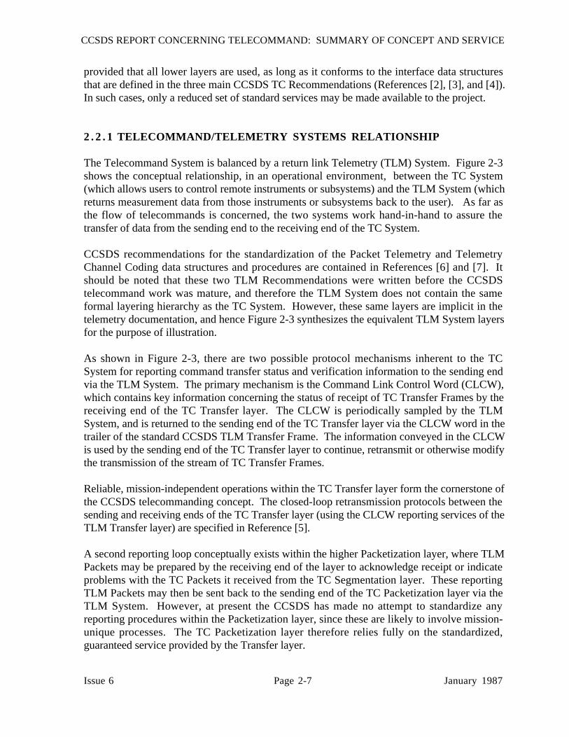
2 . 2 . 1 TELECOMMAND/TELEMETRY SYSTEMS RELATIONSHIP
The Telecommand System is balanced by a return link Telemetry (TLM) System. Figure 2-3shows the conceptual relationship, in an operational environment, between the TC System(which allows users to control remote instruments or subsystems) and the TLM System (whichreturns measurement data from those instruments or subsystems back to the user). As far asthe flow of telecommands is concerned, the two systems work hand-in-hand to assure thetransfer of data from the sending end to the receiving end of the TC System.
CCSDS recommendations for the standardization of the Packet Telemetry and TelemetryChannel Coding data structures and procedures are contained in References [6] and [7]. Itshould be noted that these two TLM Recommendations were written before the CCSDStelecommand work was mature, and therefore the TLM System does not contain the sameformal layering hierarchy as the TC System. However, these same layers are implicit in thetelemetry documentation, and hence Figure 2-3 synthesizes the equivalent TLM System layersfor the purpose of illustration.
As shown in Figure 2-3, there are two possible protocol mechanisms inherent to the TCSystem for reporting command transfer status and verification information to the sending endvia the TLM System. The primary mechanism is the Command Link Control Word (CLCW),which contains key information concerning the status of receipt of TC Transfer Frames by thereceiving end of the TC Transfer layer. The CLCW is periodically sampled by the TLMSystem, and is returned to the sending end of the TC Transfer layer via the CLCW word in thetrailer of the standard CCSDS TLM Transfer Frame. The information conveyed in the CLCWis used by the sending end of the TC Transfer layer to continue, retransmit or otherwise modifythe transmission of the stream of TC Transfer Frames.
Reliable, mission-independent operations within the TC Transfer layer form the cornerstone ofthe CCSDS telecommanding concept. The closed-loop retransmission protocols between thesending and receiving ends of the TC Transfer layer (using the CLCW reporting services of theTLM Transfer layer) are specified in Reference [5].
A second reporting loop conceptually exists within the higher Packetization layer, where TLMPackets may be prepared by the receiving end of the layer to acknowledge receipt or indicateproblems with the TC Packets it received from the TC Segmentation layer. These reportingTLM Packets may then be sent back to the sending end of the TC Packetization layer via theTLM System. However, at present the CCSDS has made no attempt to standardize anyreporting procedures within the Packetization layer, since these are likely to involve mission-unique processes. The TC Packetization layer therefore relies fully on the standardized,guaranteed service provided by the Transfer layer.

CCSDS REPORT CONCERNING TELECOMMAND: SUMMARY OF CONCEPT AND SERVICE
Issue 6 Page 2-8 January 1987
SENDING TC APPLICATION
PROCESS LAYER
SENDING TCSYSTEM MGMT
LAYER
RECEIVING TLM PACKETIZATION
LAYERSENDING TC PACKETIZATION
LAYER
RECEIVING TLM SEGMENTATION
LAYERSENDING TC SEGMENTATION
LAYER
RECEIVING TLM TRANSFER
LAYERSENDING TCTRANSFER
LAYER
RECEIVING TLM CODING LAYERSENDING TC
CODING LAYER
RECEIVING TLM PHYSICAL
LAYERSENDING TC PHYSICAL
LAYER
RECEIVING TCAPPLICATION
PROCESS LAYER
RECEIVING TCSYSTEM MGMT
LAYER
SENDING TLM PACKETIZATION
LAYERRECEIVING TCPACKETIZATION
LAYER
SENDING TLM SEGMENTATION
LAYERRECEIVING TCSEGMENTATION
LAYER
SENDING TLM TRANSFER
LAYERRECEIVING TCTRANSFER
LAYER
SENDING TLM CODING LAYERRECEIVING TC
CODING LAYER
SENDING TLM PHYSICAL
LAYERRECEIVING TCPHYSICAL
LAYER
CLCWCLCW
CMDEVENT RECEIVING TLM
APPLICATION PROCESS LAYER
RECEIVING TLMSYSTEM MGMT
LAYER
SENDING TLM APPLICATION
PROCESS LAYER
SENDING TLM SYSTEM MGMT
LAYER
*
*
*
*
THESE LAYERS DO NOT EXIST IN REFERENCE [5].*
PKT
Figure 2-3: Telecommand/Telemetry System Orientation
CCSDS REPORT CONCERNING TELECOMMAND: SUMMARY OF CONCEPT AND SERVICE
Issue 6 Page 2-9 January 1987
The final verification of proper command delivery and execution is, of course, provided whenthe user observes the effect of the command via measurement data received from the TLMSystem.
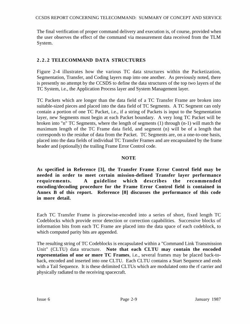
2 . 2 . 2 TELECOMMAND DATA STRUCTURES
Figure 2-4 illustrates how the various TC data structures within the Packetization,Segmentation, Transfer, and Coding layers map into one another. As previously noted, thereis presently no attempt by the CCSDS to define the data structures of the top two layers of theTC System, i.e., the Application Process layer and System Management layer.
TC Packets which are longer than the data field of a TC Transfer Frame are broken intosuitable-sized pieces and placed into the data field of TC Segments. A TC Segment can onlycontain a portion of one TC Packet, i.e., if a string of Packets is input to the Segmentationlayer, new Segments must begin at each Packet boundary. A very long TC Packet will bebroken into "n" TC Segments, where the length of segments (1) through (n-1) will match themaximum length of the TC Frame data field, and segment (n) will be of a length thatcorresponds to the residue of data from the Packet. TC Segments are, on a one-to-one basis,placed into the data fields of individual TC Transfer Frames and are encapsulated by the frameheader and (optionally) the trailing Frame Error Control code.
NOTE
As specified in Reference [3], the Transfer Frame Error Control field may beneeded in order to meet certain mission-defined Transfer layer performancerequirements. A guideline which describes the recommendedencoding/decoding procedure for the Frame Error Control field is contained inAnnex B of this report. Reference [8] discusses the performance of this codein more detail.
Each TC Transfer Frame is piecewise-encoded into a series of short, fixed length TCCodeblocks which provide error detection or correction capabilities. Successive blocks ofinformation bits from each TC Frame are placed into the data space of each codeblock, towhich computed parity bits are appended.
The resulting string of TC Codeblocks is encapsulated within a "Command Link TransmissionUnit" (CLTU) data structure. Note that each CLTU may contain the encodedrepresentation of one or more TC Frames, i.e., several frames may be placed back-to-back, encoded and inserted into one CLTU. Each CLTU contains a Start Sequence and endswith a Tail Sequence. It is these delimited CLTUs which are modulated onto the rf carrier andphysically radiated to the receiving spacecraft.
CC
SDS R
EPO
RT
CO
NC
ER
NIN
G T
EL
EC
OM
MA
ND
: SUM
MA
RY
OF C
ON
CE
PT A
ND
SER
VIC
E
Issue 6P
age 2-10January 1987
SEGMENTATION•
TC PACKET PKT HDR USER DATA
SEG HDR SEG HDR SEG HDR
FRM HDR FRM HDR FRM HDR
CB#1 CB#2 CB#N• • • CB#1 CB#2
ST SEQTAIL SEQST SEQ
CLTU 1 CLTU 2
FRAMECONSTRUCTION
•
CODEBLOCKCONSTRUCTION
•
COMMAND LINKTRANSMISSIONUNITCONSTRUCTION
•
THE DATA FIELD OF EACH CLTU CONTAINS THE ENCODEDREPRESENTATION OF ONE OR MORE TRANSFER FRAMES.
NOTE:
K BITS K BITS K BITS K BITS K BITS
Figure 2-4: Telecommand Data Structures

CCSDS REPORT CONCERNING TELECOMMAND: SUMMARY OF CONCEPT AND SERVICE
Issue 6 Page 2-11 January 1987
2 . 2 . 3 COMMUNICATIONS SECURITY/DATA PROTECTION CONCEPT
For many missions there is a requirement to prevent any intentional or accidental attempts tomanipulate or control the spacecraft by an unauthorized party, including efforts to deny accessto authorized users. Some missions may also have requirements to render the contents oftelecommand messages unintelligible to unauthorized users. The CCSDS has developed atelecommand data protection concept, which is described in Annex C of this report, thatpermits authentication and encryption measures to be implemented when required by aparticular mission.
2 . 2 . 4 TELECOMMAND SYSTEM PERFORMANCE
Performance considerations associated with the CCSDS TC System are discussed in Annex Dof this report.

CCSDS REPORT CONCERNING TELECOMMAND: SUMMARY OF CONCEPT AND SERVICE
Issue 6 Page 3-1 January 1987
3 TELECOMMAND SERVICES
This section summarizes the services, functions, inputs, and outputs characterizing each layerof the Telecommand System. The component layers are discussed for both the sending end(where the user resides) and the receiving end (where the control actions are effected).
3 . 1 TC DATA MANAGEMENT SERVICE
The Data Management Service, Reference [2], provides the primary user interface with the TCSystem. This service enables user requests for command activity to be generated, integrated,aggregated, translated, and scheduled for delivery to a spacecraft.
3 . 1 . 1 TC APPLICATION PROCESS LAYER
The basic service of the Application Process layer is to provide users with a method by whichthey can formulate instructions to control a remote device in space, and to interface thoseinstructions with the systems which provide the physical delivery of telecommands. Figure 3-1depicts the activities and interfaces of the Application Process layer.
Inputs to the sending end of the layer take the form of user requests for specific commandactions, plus associated requests concerning any desired overall delivery and executionconditions. The user command requests are translated into corresponding machineinterpretable "command directives" which are passed to the layer below, along with controlinstructions to lower layers that specify the overall configuration of the TC System required fortheir delivery. Control instructions are also sent ACROSS the layer (to the peer applicationprocess in space) to define the overall conditions which must exist within that process at thetime of execution of the command directives.
At the receiving end of the Application Process layer, named sets of command directives, andtheir associated delivery status information, are received from the System Management layer.The receiving application process executes the command directives when specified operationalconditions are satisfied: the resulting executed command actions cause changes in the state ofspacecraft instruments or subsystems, which may be observed and confirmed by the user viatelemetered measurements.

CCSDS REPORT CONCERNING TELECOMMAND: SUMMARY OF CONCEPT AND SERVICE
Issue 6 Page 3-2 January 1987
INPUT: USER REQUESTS FORCOMMAND ACTIONS.DELIVERY INSTRUCTIONS.
FUNCTION: TRANSLATE USERREQUESTS TO NAMED SETSOF CMD DIRECTIVES ANDEXECUTION CONDITIONS.TRANSLATE DELIVERYINSTRUCTIONS TO OVERALLSESSION CONTROLPARAMETERS (DELIVERYREQUIREMENTS).
OUTPUT: NAMED SETS OF CMDDIRECTIVES, DELIVERYREQUIREMENTS. EXECUTIONCONDITIONS.
OUTPUT: EXECUTED COMMAND ACTIONS WHICHCHANGE SPACECRAFT STATE.
FUNCTION: EXECUTE NAMEDSET OF COMMAND DIRECTIVESWHEN OPERATIONALCONDITIONS ARE MET.
INPUT: NAMED SETS OF CMDDIRECTIVES, EXECUTIONCONDITIONS.
SERVICE
CONTROL
REMOTE
PROCESSES
COMMAND
DIRECTIVES
UNDEFINED
USER SUBSYSTEM
RECEIVINGEND
PEERPROCESS
SENDINGEND
APPLICATION PROCESS LAYER
SYSTEM MANAGEMENT LAYER
Figure 3-1: TC Application Process Layer

CCSDS REPORT CONCERNING TELECOMMAND: SUMMARY OF CONCEPT AND SERVICE
Issue 6 Page 3-3 January 1987
3.1.2 TC SYSTEM MANAGEMENT LAYER
The basic service of the TC System Management layer is to provide translation of commanddirectives into transportable telecommand application data units, supervise their delivery tothe receiving end of the layer, and to translate the application data back into commanddirectives (if required) prior to delivery to the receiving application process. Figure 3-2depicts the activities and interfaces of the TC System Management layer.
INPUT: NAMED SETS OF CMDDIRECTIVES. DELIVERY RQMTSEXECUTION CONDITIONS.
FUNCTION: TRANSLATE NAMED SETS OF COMMANDDIRECTIVES TO NAMED SETSOF TRANSPORTABLEAPPLICATION DATA UNITS.MANAGE TC SESSIONS.SPECIFY TRANSPORTCONTROL PARAMETERS.CONSTRAINT CHECKING.
OUTPUT: NAMED SETS OF APPLICATION DATA.TRANSPORT CONTROLPARAMETERS.
OUTPUT: NAMED SETS OF CMDDIRECTIVES. EXECUTIONCONDITIONS.
FUNCTION: DELIVER NAMEDSETS OF TC APPLICATIONDATA (TRANSLATED TONAMED SETS OF COMMANDDIRECTIVES, IF REQUIREDBY APPLICATION PROCESS).GENERATE DELIVERY STATUSREPORTS FOR TELEMETRYSYSTEM.
INPUT: NAMED SETS OF TCAPPLICATION DATA.
SERVICE
DELIVER TC
APPLICATION
DATA
TELECOMMAND
APPLICATION
DATA UNITS
UNDEFINED
APPLICATION PROCESS LAYER
RECEIVINGEND
PEERPROCESS
SENDINGEND
SYSTEM MANAGEMENT LAYER
PACKETIZATION LAYER
Figure 3-2: TC System Management Layer

CCSDS REPORT CONCERNING TELECOMMAND: SUMMARY OF CONCEPT AND SERVICE
Issue 6 Page 3-4 January 1987
Inputs at the sending end of the TC System Management layer are integrated, aggregated, andnamed sets of multi-user command directives, along with control instructions specifying theiroverall delivery requirements. The named command directives are parsed by the SystemManagement layer and translated (if required) into correspondingly named sets of TCapplication data which are compatible with handling by the layer below.
The TC application data are partitioned into appropriate blocks for transmission duringindividual TC sessions, and (along with necessary control instructions) are passed to the layerbelow for transport. At the receiving end of the TC System Management layer, named sets ofuser application data may (if required by the application processes) be translated back intocorrespondingly named sets of command directives, or may be passed directly to the layerabove. Status reports may be formulated and returned to the sending end of the layer (viaTelemetry Packets) if information relating to the correctness, completeness, and sequentiality ofthe received data is required by particular mission processes: the CCSDS presently does notdefine these reports.
Session control instructions are created by the sending end of the System Management layer,which are addressed to the receiving end of the layer and are passed to the layer below fortransport. These session control instructions to the receiving end of the layer define namingconventions and conditions for delivering either the application data or the retranslatedcommand directives to the TC Application Process layer.
3 . 1 . 3 TC PACKETIZATION LAYER
The TC Packetization layer is currently the highest layer which CCSDS Recommendationscover in detail. The TC Packet is an autonomous command data unit which may be directlyinterpreted by the device that is being controlled. The format of the TC Packet is specified inReference [2].
The basic service of the TC Packetization layer is to provide error-free transport of one set ofapplication data to the System Management layer on the spacecraft. An enhanced service is toprovide error-free transport of the application data content of named sets of interdependent TCPackets (i.e., TC Files) to the TC System Management layer on the spacecraft. Figure 3-3depicts the activities and interfaces of the TC Packetization layer.
Inputs to the sending end of the Packetization layer are named sets of transportable TCapplication data, plus transport control instructions including naming conventions. The TCapplication data are placed within the data field of TC Packets, and encapsulated within Packetheaders containing information such as the name of destination application, sequence control,and packet length. If required, TC Files are constructed according to the procedures defined inReference [2].
The TC Packets, or files of TC Packets, are passed to the layer below along with controlinstructions that request lower layer services such as the segmentation or multiplexing ofpackets or files. TC Packets may also be created for routing to the receiving end of the

CCSDS REPORT CONCERNING TELECOMMAND: SUMMARY OF CONCEPT AND SERVICE
Issue 6 Page 3-5 January 1987
INPUT: NAMED SETS OF APPLI-CATION DATA. TRANSPORTCONTROL PARAMETERS.
FUNCTION: ENCAPSULATEAPPLICATION DATA INTOTC PACKETS OR FILESOF TC PACKETS.REQUEST DATA ROUTINGSERVICE (E.G., MULTIPLEXERACCESS POINTS).
OUTPUT: TC PACKETS.TC FILES.ROUTING INSTRUCTIONS.
OUTPUT: NAMED SETS OFAPPLICATION DATA.
FUNCTION: EXTRACT ANDRECONSTRUCT NAMED SETSOF APPLICATION DATA IN SEQUENTIAL ORDER.FORMULATE TRANSPORTSTATUS REPORTS.
INPUT: TC PACKETS.TC FILES.
SERVICE
END-TO-END
TRANSPORT–TC
APPLICATION
DATA
TELECOMMAND
PACKETS
UNDEFINED
RECEIVINGEND
PEERPROCESS
SENDINGEND
PACKETIZATION LAYER
SEGMENTATION LAYER
SYSTEM MANAGEMENT LAYER
Figure 3-3: TC Packetization Layer
Packetization layer, containing control instructions which define the system conditions thatmust exist before the TC application data are passed back across the interface to the TC SystemManagement layer.
At the receiving end of the TC Packetization layer, the named sets of TC application data areextracted from the data fields of the TC Packets in the sequential order in which they weregiven at the sending end, and passed to the layer above. Status reports may be formulated andreturned to the sending end of the layer (via Telemetry Packets) if information relating to thecorrectness, completeness, and sequentiality of the received data is required by particularmission processes: the CCSDS presently does not define these reports.
It should be noted that many of the telecommanding functions within and above the

CCSDS REPORT CONCERNING TELECOMMAND: SUMMARY OF CONCEPT AND SERVICE
Issue 6 Page 3-6 January 1987
Packetization layer will probably be implemented within user application processes, such as theinstrument and subsystems themselves, rather than as external supporting services.
3 . 2 TC DATA ROUTING SERVICE
The TC Data Routing Service provides a pivotal function within the TC System by performingthe error-controlled communication of higher layer TC data through the ground-to-space datalink, relying on the lower layer TC Channel Service in order to perform its task. Thecombination of the Data Routing and Channel Services provides users with a powerfulmechanism for the flow control and guaranteed transfer of TC data between the sending andreceiving ends of the TC System. The CCSDS therefore has focussed its attention on fullyspecifying these services so that robust, mission-independent user support systems may berapidly developed. The Data Routing Service contains two layers: the TC Segmentationlayer and the TC Transfer layer. The detailed protocols and formats for the TC DataRouting Service are specified in References [3] and [5].
3 . 2 . 1 TC SEGMENTATION LAYER
The TC Segmentation layer is optional, i.e., it may be bypassed if its services are not required.
The basic service of the Segmentation layer is to prepare variable-length TC data units from thelayer above (e.g., TC Packets, or other user-supplied data structures) for transfer through thespace data link, using the lower TC Transfer layer service. Since the data unit of the TCTransfer layer (the TC Frame) has an upper length limit, the Segmentation layer must break thehigher layer TC data units into suitable sized pieces for insertion into the data field of the frame.A second aspect of its service is the capability to multiplex together segments of data fromdifferent TC data units for the purpose of flow control: to accomplish this, the Segmentationlayer provides "Multiplexer Access Points" (MAPs) to the layer above. Figure 3-4 depicts theactivities and interfaces of the TC Segmentation layer.
TC Packets (or other higher layer user data structures) are input to the sending end of the layer,plus data routing control instructions (assignment of TC Packets or TC Files to particularMAPs). The input data are first broken into pieces (segments) which will fit into the data fieldof the lower layer TC Transfer Frames. Each segment must only contain a piece of ONE inputdata unit, i.e., a new segment must be started at each boundary between higher layer data units.Every segment is labelled with a Segment Header that conveys segment order. The segment isfurther labelled to identify with which multiplexing port it is associated, so that it may beproperly routed and reconstructed at the receiving end: this is accomplished by assigning aMAP identifier to each segment, also conveyed in the Segment Header. The completed TCSegment is output to the layer below, the TC Transfer layer, for encapsulation within the datafield of one TC Transfer Frame.

CCSDS REPORT CONCERNING TELECOMMAND: SUMMARY OF CONCEPT AND SERVICE
Issue 6 Page 3-7 January 1987
INPUT: TC PACKETS.TC FILES.
FUNCTION: SEGMENT SETSOF PACKETS TO FITTRANSFER FRAMES.MULTIPLEX SEGMENTS BYMULTIPLEXER ACCESSPOINT (MAPs).
OUTPUT: SEGMENTS ANDDELIVERY CONDITIONS.
OUTPUT: TC PACKETS.TC FILES.
FUNCTION: RECONSTRUCTSETS OF PACKETS FROMSEGMENTS.
INPUT: SEGMENTS.
SERVICE
INTERFACE
PACKETS WITH
TRANSFER
LAYER
SEGMENTS
NONE
PACKETIZATION LAYER
RECEIVINGEND
PEERPROCESS
SENDINGEND
SEGMENTATION LAYER
TRANSFER LAYER
Figure 3-4: TC Segmentation Layer
At the receiving end of the TC Segmentation layer, TC Segments are received from the layerbelow, sorted by MAP, and the individual higher layer TC data units are reconstructed prior topassing them across the interface to the layer above. Since the Segmentation layer reliescompletely on the guaranteed delivery service of the layer below, it contains no layer-uniquereporting procedures.
Appreciating the functional utility of the multiplexing feature of the Segmentation layer requiresan understanding of the characteristics of the underlying Transfer layer. The Transfer layer,which utilizes TC Frames as its data units, interfaces with the single physical data channel inthe layer below it. The TC Frames themselves feature an independent multiplexing capability,since each frame may be assigned with its own "Virtual Channel" (VC) identifier. IndividualTC Frames may (by giving them different VC identifiers) each carry different higher layer TC

CCSDS REPORT CONCERNING TELECOMMAND: SUMMARY OF CONCEPT AND SERVICE
Issue 6 Page 3-8 January 1987
data units: this therefore provides a Transfer layer multiplexing capability which is functionallysimilar to the Segmentation layer MAPs.
However, since the Transfer layer contains the closed-loop retransmission procedures whichcontrol the delivery of TC Frames to the spacecraft, having a large number of VCs that aresimultaneously "open" will increase the complexity of the reporting mechanism between thereceiving and sending end of this layer. The MAP feature of the Segmentation layer allows theuser data multiplexing to be performed ABOVE the Transfer layer, i.e., on one VirtualChannel, thus potentially simplifying the Transfer layer reporting and reducing its associatedtelemetered traffic. Conversely, it is important to recognize that this potential simplification ofthe Transfer layer is bought at the price of the increased complexity and communicationsoverhead associated with the Segmentation layer.
Missions are therefore free to decide whether or not to implement a Segmentation layer: if thehigher layer TC data units (e.g., TC Packets) are all short enough to fit within a maximum-length TC Transfer Frame (and the reporting complexity is acceptable), the Virtual Channelfeature of the TC Transfer Frame may be used for multiplexing, and the Segmentation layermay be completely omitted. It will be noted when reading Reference [3] that the CCSDSRecommendations theoretically allow up to 64 Virtual Channels in the Transfer layer, each withup to 64 MAPs attached to it within the Segmentation layer. This theoretically hugemultiplexing capability is an artifact of the decision to provide alternative multiplexingmechanisms, and a real implementation will usually use a much more restricted repertoire ofMAP and VC capabilities.
3 . 2 . 2 TC TRANSFER LAYER
The basic service of the TC Transfer layer is the GUARANTEED error-free communication ofhigher layer TC data units to the receiving end of the layer above, correct and without omissionor duplication, and in the same sequential order in which they were received from the layerabove at the sending end. THIS GUARANTEED SERVICE IS CENTRAL TO THEOPERATING PHILOSOPHY OF THE TC SYSTEM: the Transfer layer is therefore the"core" of the standard CCSDS telecommanding concept. In order to provide this service, theTC Transfer layer draws upon the supporting lower layer TC Channel Service. Figure 3-5depicts the activities and interfaces of the TC Transfer layer.
The sending end of the TC Transfer layer encapsulates each higher layer TC data unit (e.g., TCPacket, TC Segment or a non-standard user data structure) within the data field of a TCTransfer Frame: one (and ONLY one) TC data unit is inserted into the data field of each frame.The header of the TC Frame contains key data link control information such as spacecraft andVirtual Channel identification, frame sequence number, and frame length.
The operating configuration of the TC Transfer layer is specified by control instructionsreceived from higher layers. The sending end of the Transfer layer formulates special TC
Transfer Frames called "Control Commands" which it transmits to a "Frame Acceptance and

CCSDS REPORT CONCERNING TELECOMMAND: SUMMARY OF CONCEPT AND SERVICE
Issue 6 Page 3-9 January 1987
INPUT: SEGMENTS.DELIVERY CONDITIONS.
FUNCTION: ENCAPSULATESEGMENTS AND DELIVERYCONDITIONS INTOTRANSFER FRAMES.MULTIPLEX FRAMES BYVIRTUAL CHANNEL.MONITOR FRAME ACCEPTANCE.INITIATE TRANSMISSION/RETRANSMISSION AS REQ'D.
OUTPUT: BUFFER OF TC DATABITS (REPRESENTING, E.G.,TRANSFER FRAMES).
OUTPUT: SEGMENTS.
FUNCTION: RECONSTITUTEORDERED SET OF TRANSFERFRAMES. PERFORM FRAMEACCEPTANCE ANDVALIDATION CHECKS. REPORT STATUS OF SAME VIACONSTRUCTED CLCWs.EXTRACT SEGMENTS.
INPUT: "CLEAN" TC DATA PLUSFILL BITS. DATA START/STOPINDICATORS. STATUS
SERVICE
RELIABLY
DELIVER
TRANSFER
FRAMES
TRANSFER
FRAMES
COMMAND LINK
CONTROL WORD
(CLCW)
SEGMENTATION LAYER
RECEIVINGEND
PEERPROCESS
SENDINGEND
TRANSFER LAYER
CODING LAYER
Figure 3-5: TC Transfer Layer
Reporting Mechanism" (FARM) at the receiving end of the layer in order to set up the receivingparameters.
The sending end of the layer passes the assembled TC Frames to a "Frame OperationProcedure" (FOP), which provides the control of their transmission to the spacecraft. TheFOP batches the TC Frames and delivers them to the layer below (the Coding layer) as buffersof serial information bits (corresponding to one or more back-to-back frames) for encoding andtransmission to the spacecraft.
At the receiving end of the TC Transfer layer, the inputs from the layer below are "clean"decoded information bits and data stop/start indicators which mark the gross boundaries of thebuffers of bits that were given to the Coding layer at the sending end: however, trailing fill bits

CCSDS REPORT CONCERNING TELECOMMAND: SUMMARY OF CONCEPT AND SERVICE
Issue 6 Page 3-10 January 1987
may have been inserted by the encoding process. The Transfer layer therefore uses the lengthinformation in each TC Frame to delimit each frame in the buffer, and to discard any trailingfill.
The reconstructed, delimited frames are input to the receiving-end FARM, which performsvalidation and acceptance checks based on sequence information and other criteria that are fullyspecified in Reference [3]. The status of frame acceptance by the FARM is telemetered back tothe FOP at the sending end via the Command Link Control Word (CLCW) in the trailers ofstandard Telemetry Transfer Frames. The pair of peer-layer procedures executed by the FOPand FARM are together known as a "Command Operation Procedure" (COP). Based onCLCW reports from the FARM, the FOP makes appropriate retransmission decisions forframes which were rejected or otherwise missed by the FARM, according to the rules of thegoverning COP.
Under closed-loop retransmission control of the selected COP, and utilizing the error-protection services of lower layers, the TC Frames are assembled at the receiving end of thelayer so that they are error-free, in sequence and with no omission or duplication. Once thisservice is guaranteed, their data contents are then stripped and passed to higher layers.
Three COPs, which are recursively related to each other, are presently defined. In order ofincreasing complexity they are:
(1) COP-0
COP-0 operates on the principle of sequential frame acceptance and retransmission,without frame sequence numbering. The FOP initiates the transmission of TCFrames whose sequence numbers are not used. The FARM only accepts frames ifthey are received without detected error. As soon as an error is encountered, theFARM enters a lockout condition and rejects all subsequent frames until reset by aControl Command from the FOP. The FOP monitors a CLCW counter, generatedby the FARM, that indicates how many good frames were accepted. When itobserves the FARM in lockout, it uses this counter to compute how far to back up,sends an unlock command, and begins retransmission.
(2) COP-1
COP-1 operates on the principle of sequential frame acceptance and retransmission,with frame sequence numbering. The FOP initiates the transmission of TC Frameswhose sequence numbers are arranged in upcounting sequential order. The FARMonly accepts frames if their sequence numbers match the expected upcountingorder. As soon as a sequence error is encountered, the FARM rejects allsubsequent frames whose sequence numbers do not match the expected order. TheFOP monitors the CLCW to determine if frames are being rejected, and if so backsup and retransmits the series of frames, beginning with the frame whose sequencenumber matches the number which the FARM is expecting.
CCSDS REPORT CONCERNING TELECOMMAND: SUMMARY OF CONCEPT AND SERVICE
Issue 6 Page 3-11 January 1987
(3) COP-2
COP-2 operates on the principle of sequence-independent frame acceptance andselective retransmission, with frame sequence numbering. The FOP initiates thetransmission of TC Frames whose sequence numbers are originally arranged inupcounting sequential order. Although nominally expecting the received frames tobe in sequential order, the FARM will accept any frame whose sequence numberfalls within certain allowable windows. Any discontinuities in the receivedsequence are noted by the FARM, and the sequence numbers of detected "missing"frames are reported to the FOP via telemetered CLCWs. The FOP then schedulesthe retransmission of these missing frames at an opportune time.
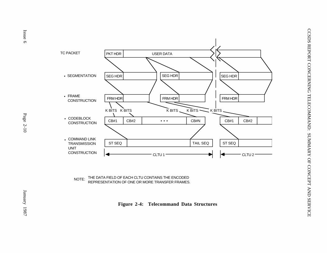
Since the numbering of frames is a key feature of COP-1 and COP-2, it is important tounderstand the terminology which is used within the CCSDS Recommendations:
(1) The FOP, which is the numbering authority, maintains a master counter whichassigns the frame sequence number. The current value of this master counter, i.e.,the number which will be assigned to the NEXT TC Frame, is called V(S).
(2) The frame sequence number which is contained within any particular transmittedTC Frame is called N(S).
(3) The FARM maintains a counter which contains the value of the next TC Framesequence number which it expects to receive. The current value of this counter iscalled V(R).
(4) The telemetered CLCW contains reports of the observed values of V(R). Theobserved value of V(R), received by the FOP in a particular CLCW, is called N(R).
This relationship is summarized in Figure 3-6.
FOP"V (S)"
FARM"V (R)"
TC FRAME
CLCW
SENDING END RECEIVING END
"N (S)"
"N (R)"
COP
Figure 3-6: Transfer Layer Numbering Relationships
CCSDS REPORT CONCERNING TELECOMMAND: SUMMARY OF CONCEPT AND SERVICE
Issue 6 Page 3-12 January 1987
3 . 3 TC CHANNEL SERVICE
Operation of the TC Channel Service begins when at least one complete TC Transfer Frame isprepared for radiation through the telecommand channel to the spacecraft. The TC ChannelService provides error-controlled transmission of the TC Frame(s) through the channel. Errorcontrol is achieved via forward error detection/correction techniques. The TC Channel Serviceis composed of two layers, the Coding layer and the Physical layer. The operating datastructures and protocols for the Channel Service are specified in Reference [4].
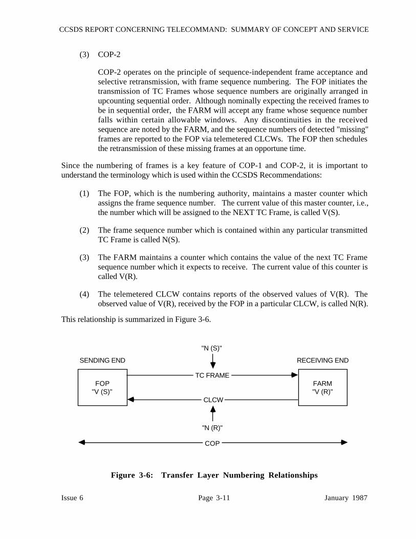
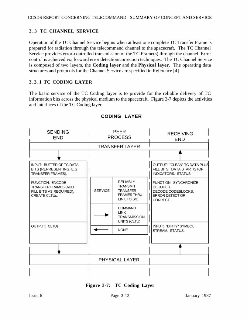
3 . 3 . 1 TC CODING LAYER
The basic service of the TC Coding layer is to provide for the reliable delivery of TCinformation bits across the physical medium to the spacecraft. Figure 3-7 depicts the activitiesand interfaces of the TC Coding layer.
INPUT: BUFFER OF TC DATABITS (REPRESENTING, E.G.,TRANSFER FRAMES).
FUNCTION: ENCODETRANSFER FRAMES (ADDFILL BITS AS REQUIRED).CREATE CLTUs.
OUTPUT: CLTUs
OUTPUT: "CLEAN" TC DATA PLUSFILL BITS. DATA START/STOPINDICATORS. STATUS
FUNCTION: SYNCHRONIZEDECODER.DECODE CODEBLOCKS.ERROR DETECT OR CORRECT.
INPUT: "DIRTY" SYMBOLSTREAM. STATUS.
SERVICE
RELIABLYTRANSMITTRANSFERFRAMES THRULINK TO S/C
COMMANDLINKTRANSMISSIONUNITS (CLTU)
NONE
TRANSFER LAYER
RECEIVINGEND
PEERPROCESS
SENDINGEND
CODING LAYER
PHYSICAL LAYER
Figure 3-7: TC Coding Layer

CCSDS REPORT CONCERNING TELECOMMAND: SUMMARY OF CONCEPT AND SERVICE
Issue 6 Page 3-13 January 1987
Inputs to the sending end of the Coding layer are buffers of TC information bits from the layerabove. Each buffer corresponds to one or more serial, back-to-back TC Transfer Frames. Theinformation bits are encoded, piece by piece, into short fixed length TC Codeblocks, whoseformat and encoding technique is specified in Reference [4]. Each Codeblock contains paritybits that provide error detection or correction capabilities for the information bits. Fill bits maybe added by the Coding layer to complete the last Codeblock.
The sequence of TC Codeblocks (i.e., the symbol representation of one or more TC Framesplus any appended fill) is then encapsulated into a Command Link Transmission Unit (CLTU).The boundaries of the CLTU are delimited for the receiving end of the Coding layer by theStart and Tail sequences. The delimited CLTUs are passed to the layer below, the TC Physicallayer, for modulation onto the space data channel.
At the receiving end of the TC Coding layer, a "dirty" (potentially corrupted by channel noise)symbol stream plus control information (e.g., whether the physical channel is active orinactive) is received from the layer below. Searching for the Start sequence, the Coding layerfinds the boundaries of the CLTU, synchronizes the decoder with the TC Codeblocks, anddecodes them. The decoder may operate in an error-detecting-only mode, or may optionallyperform error correction. If no errors are detected, or (optionally) if errors are detected andcorrected, the Coding layer passes "clean" octets of decoded TC data to the layer above(including any appended fill): CLTU Start and Tail Sequences, which are not decodablecodeblocks, are not transferred. Should an (optionally uncorrectable) error be estimated to haveoccurred within any TC Codeblock within a given sequence, the remainder of the sequence isdiscarded and no further data are passed to the layer above until the Coding layer is reset by thedetection of another Start sequence. There are no reporting mechanisms between the receivingand sending ends of the Coding layer.
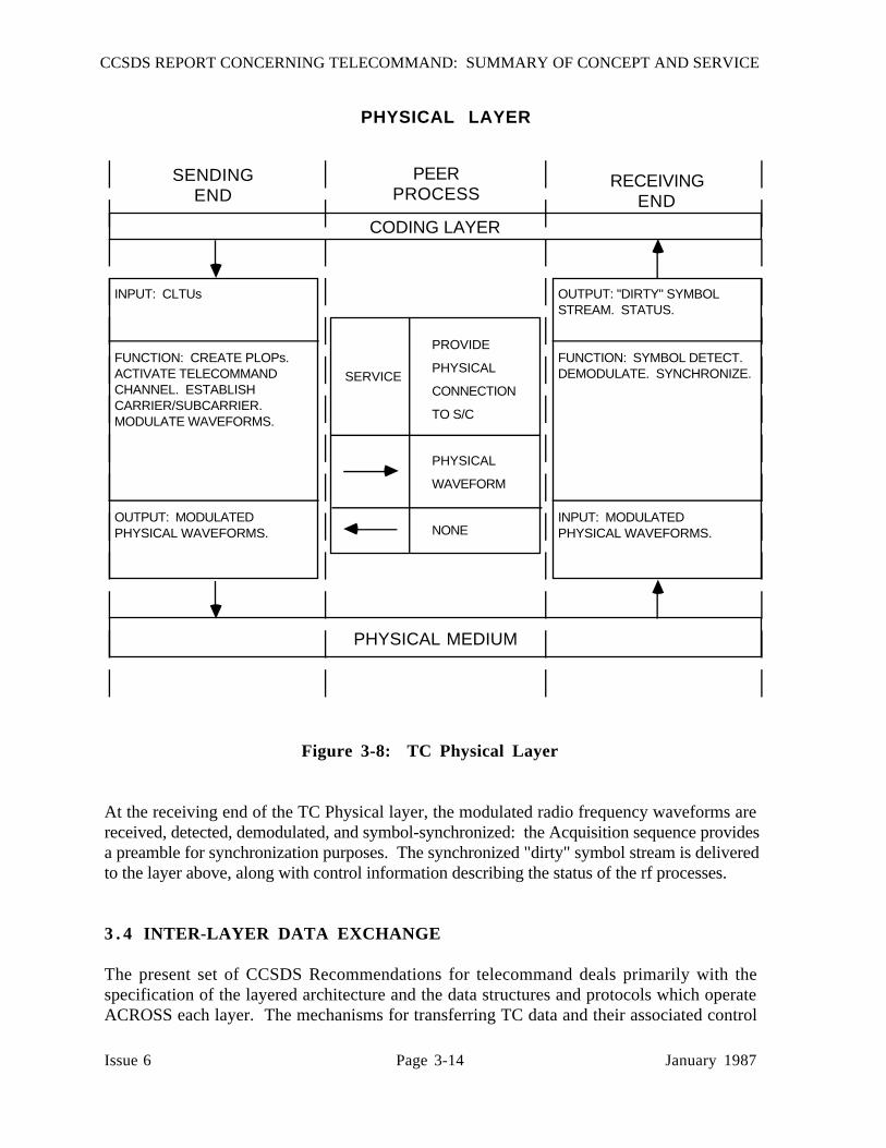
3 . 3 . 2 TC PHYSICAL LAYER
The service of the TC Physical layer is to provide a physical connection, via radio signals,between the transmitting station and the receiving spacecraft. Figure 3-8 depicts the activitiesand interfaces of the TC Physical layer.
Inputs to the sending end of the Physical layer are CLTUs, plus control information from thelayer above defining the requested transmission services. The Physical layer controls theactivation and deactivation of the physical channel by invoking various "Physical LayerOperations Procedures" (PLOPs).
A PLOP consists of sequential application of different "Carrier Modulation Modes" (CMMs).The CMMs include an unmodulated carrier, a carrier modulated with an Acquisition sequence,a carrier modulated with TC symbols corresponding to one CLTU, and a carrier modulatedwith an Idle sequence. Using an appropriate PLOP, the CLTUs are radiated to the spacecraftas physical waveforms.
CCSDS REPORT CONCERNING TELECOMMAND: SUMMARY OF CONCEPT AND SERVICE
Issue 6 Page 3-14 January 1987
INPUT: CLTUs
FUNCTION: CREATE PLOPs.ACTIVATE TELECOMMANDCHANNEL. ESTABLISHCARRIER/SUBCARRIER.MODULATE WAVEFORMS.
OUTPUT: MODULATEDPHYSICAL WAVEFORMS.
OUTPUT: "DIRTY" SYMBOLSTREAM. STATUS.
FUNCTION: SYMBOL DETECT.DEMODULATE. SYNCHRONIZE.
INPUT: MODULATEDPHYSICAL WAVEFORMS.
SERVICE
PROVIDE
PHYSICAL
CONNECTION
TO S/C
PHYSICAL
WAVEFORM
NONE
CODING LAYER
RECEIVINGEND
PEERPROCESS
SENDINGEND
PHYSICAL LAYER
PHYSICAL MEDIUM
Figure 3-8: TC Physical Layer
At the receiving end of the TC Physical layer, the modulated radio frequency waveforms arereceived, detected, demodulated, and symbol-synchronized: the Acquisition sequence providesa preamble for synchronization purposes. The synchronized "dirty" symbol stream is deliveredto the layer above, along with control information describing the status of the rf processes.
3 . 4 INTER-LAYER DATA EXCHANGE
The present set of CCSDS Recommendations for telecommand deals primarily with thespecification of the layered architecture and the data structures and protocols which operateACROSS each layer. The mechanisms for transferring TC data and their associated control

CCSDS REPORT CONCERNING TELECOMMAND: SUMMARY OF CONCEPT AND SERVICE
Issue 6 Page 3-15 January 1987
instructions BETWEEN the layers are currently left unspecified. However, the CCSDS iscurrently developing a concept for a general set of "standard data interchange structures"(Reference [9]) which could facilitate such inter-layer communication, particularly at thesending end of the TC System. Instances of standard data interchange structures known as"Standard Formatted Data Units" (SFDUs) will probably be developed to perform theinterconnection of the sending-end layers: at present these are left as potential items of futurework for the CCSDS.
It should also be noted that the layered hierarchy does not also imply that the time-orderedFLOW of operations through the layers is necessarily sequential. For instance, it is perfectlyvalid to pre-assemble and pre-number TC Frames, pre-encode them, batch them into CLTUsand then put the prefabricated CLTUs "on the shelf" for later radiation under control of theTransfer layer FOP and the Physical layer PLOP. The inter-layer control instructions mustaccommodate such non-time-sequential operations.
3 . 5 INTER-AGENCY CROSS-SUPPORT SERVICES
A major feature of the layered CCSDS TC System architecture is its potential for providing asignificantly more comprehensive level of cross support between Agencies than is possible atpresent, thus enabling the development of simple and cost-effective interfaces for the widerange of international space missions which are anticipated in the future. However, the presentCCSDS Recommendations have not addressed the physical implications of cross support.
The CCSDS has established a systems panel to study and recommend the various inter-Agencycross-support gateways and service access points. The current status of this work may befound in Reference [10].
CCSDS REPORT CONCERNING TELECOMMAND: SUMMARY OF CONCEPT AND SERVICE
Issue 6 Page A-1 January 1987
ANNEX A
ACRONYMS AND TERMINOLOGY

CCSDS REPORT CONCERNING TELECOMMAND: SUMMARY OF CONCEPT AND SERVICE
Issue 6 Page A-2 January 1987
ACRONYMS
CCSDS: CONSULTATIVE COMMITTEE FOR SPACE DATA SYSTEMSCLCW: COMMAND LINK CONTROL WORDCLTU: COMMAND LINK TRANSMISSION UNITCMD: COMMANDCMM: CARRIER MODULATION MODECOP: COMMAND OPERATION PROCEDUREFARM: FRAME ACCEPTANCE AND REPORTING MECHANISMFOP: FRAME OPERATION PROCEDUREHDR: HEADERID: IDENTIFIERMAP: MULTIPLEXER ACCESS POINTN(R): THE VALUE OF V(R) WHICH IS OBSERVED BY THE FOP IN A
PARTICULAR CLCWN(S): THE SEQUENCE NUMBER ASSIGNED BY THE FOP TO A
PARTICULAR TRANSMITTED TC FRAMEPKT: PACKETPLOP: PHYSICAL LINK OPERATIONS PROCEDURERF, rf: RADIO FREQUENCYS/C: SPACECRAFTSEG: SEGMENTST SEQ: START SEQUENCETC: TELECOMMANDTLM: TELEMETRYVC: VIRTUAL CHANNELV(R): THE NEXT EXPECTED TC FRAME SEQUENCE NUMBER; A
COUNTER MAINTAINED BY THE FARMV(S): THE SEQUENCE NUMBER WHICH THE FOP WILL ASSIGN TO THE
NEXT TRANSMITTED TC FRAME
CCSDS REPORT CONCERNING TELECOMMAND: SUMMARY OF CONCEPT AND SERVICE
Issue 6 Page A-3 January 1987
TERMINOLOGY
ACCEPT:
Within the Transfer layer, recognition by the receiving end that a TC Frame has passed thevalidation and acceptance test criteria as programmed into the Frame Acceptance and ReportingMechanism.
APPLICATION PROCESS LAYER:
The upper layer of the Telecommand Data Management Service.
CHANNEL SERVICE:
In the space data systems layered service architecture, the bottom service of the TelecommandSystem. Among its services it delivers the encoded bits of a buffer of transfer frames acrossthe physical communications link under error-controlled conditions.
CLEAN:
Data which are declared to be error free within the error detection and (optional) errorcorrection capabilities of the TC Coding layer.
CODEBLOCK:
The protocol data unit of the TC Coding layer. A TC Codeblock contains the encoded symbolrepresentation of a small set of contiguous TC information bits.
CODING LAYER:
The upper layer of the TC Channel Service.
COMMAND:
An instruction sent from a user to a receiving application process in space in order to effect achange in that process.
COMMAND DIRECTIVE:
A machine-interpretable representation of a user-desired command action.
CCSDS REPORT CONCERNING TELECOMMAND: SUMMARY OF CONCEPT AND SERVICE
Issue 6 Page A-4 January 1987
COMMAND LINK CONTROL WORD:
The TC Transfer layer protocol data unit for telecommand reporting, which is embedded in thetrailer of a CCSDS Telemetry Transfer Frame. It conveys status information from thereceiving end to the sending end of the TC Transfer layer.
COMMAND LINK TRANSMISSION UNIT:
Within the Coding layer, the protocol data unit which carries buffers of error-protectedsymbols (corresponding to one or more encoded Telecommand Transfer Frames) duringtransfer through the data channel to the spacecraft.
COMMAND OPERATION PROCEDURE (COP):
A sequence of procedural activities designed to assure the reliable, error-controlled delivery ofTelecommand Transfer Frames. Each COP comprises a Frame Operation Procedure operatingwithin the sending end and a Frame Acceptance and Reporting Mechanism operating within thereceiving end.
CONTROL COMMAND:
A special, dedicated TC Transfer Frame containing control information to set up the receivingparameters of the spacecraft end of the TC Transfer layer.
CONTROL INSTRUCTION:
A data object which is passed between layers within the TC System in order to set up theparameters of data transfer.
DATA MANAGEMENT SERVICE:
In the space data systems layered telecommand architecture, the top service of theTelecommand System. It includes the primary facilities for interfacing the user with thesystems used to communicate telecommands. Its bottom layer provides a protocol data unitknown as a Telecommand Packet, which provides data formatting services so that commanddata may be transported between user application processes.
DATA ROUTING SERVICE:
In the space data systems layered telecommand architecture, the middle service of theTelecommand System. It provides a fundamental service within the TC System byguaranteeing the delivery of TC data from the sending to the receiving ends of the ground-to-space data link.

CCSDS REPORT CONCERNING TELECOMMAND: SUMMARY OF CONCEPT AND SERVICE
Issue 6 Page A-5 January 1987
DELIVERY:
The process of passing transported telecommand data across the interface to the ApplicationProcess layer at the receiving end of the TC System.
DELIVERY CONDITIONS:
Control instructions, generated by the Application Process layer, which specify the parametersand conditions that are required to exist within lower layers in order to perform the delivery oftelecommands from the sending to the receiving end of the TC System.
EXECUTION:
The act of effecting a commanded change within a spacecraft application process, in responseto a telecommand which has been delivered to that process.
FILE:
An ordered aggregation of interrelated Telecommand Packets corresponding to a single, welldefined spacecraft activity. A TC File has three distinguishing characteristics: 1) it has a Filename; 2) it has a pre-defined length; and 3) it must be delivered intact and complete beforebeing released for execution.
MULTIPLEXER ACCESS POINT (MAP):
An input port to the TC Segmentation layer which enables all user data units who are membersof the sequence present at that port to be uniquely identified. Use of MAPs permits differentstreams of user data to be multiplexed together onto one Virtual Channel for flow controlpurposes.
OCTET:
An 8-bit word consisting of eight contiguous bits.
PACKET:
The protocol data unit of the TC Packetization layer which facilitates the end-to-end transport ofcommand application data. The application data are encapsulated within a leading packetheader.
PACKETIZATION LAYER:
The bottom layer in the Telecommand Data Management Service.

CCSDS REPORT CONCERNING TELECOMMAND: SUMMARY OF CONCEPT AND SERVICE
Issue 6 Page A-6 January 1987
PHYSICAL LAYER:
The bottom layer of the TC Channel Service.
PHYSICAL LAYER OPERATION PROCEDURE (PLOP):
A sequence of procedural activities designed to activate and deactivate the physicaltelecommand channel by invoking radio frequency carrier and modulation techniques.
PROTOCOL:
A set of standard rules and procedures, plus their accompanying format conventions, thatdefine the orderly exchange of information between peer entities within a given layer of the TCSystem.
RELIABLE:
Meeting the data quality, quantity, continuity, and completeness performance criteria which arespecified for the Telecommand System.
SEGMENT:
The protocol data unit of the TC Segmentation layer which facilitates breaking long user dataunits into shorter, communications-oriented pieces and multiplexing them together for flowcontrol purposes.
SEGMENTATION LAYER:
The upper layer of the TC Data Routing Service.
SESSION:
A period of time throughout which the sending and receiving ends of the TC Systemcommunicate for the purpose of transferring TC data.
SYMBOL:
A serial representation of bits, or binary digits, which have been encoded to protect themagainst transmission induced errors.
SYSTEM MANAGEMENT LAYER:
The middle layer of the Telecommand Data Management Service.

CCSDS REPORT CONCERNING TELECOMMAND: SUMMARY OF CONCEPT AND SERVICE
Issue 6 Page A-7 January 1987
TELECOMMAND:
A generic term used to describe command data during the time that they are beingtelecommunicated to the spacecraft.
TELECOMMAND SYSTEM:
The end-to-end system of layered space mission telecommunication services which exist toenable a user to send commands, in a reliable and transparent error-controlled environment, toreceiving elements in space.
TRANSFER FRAME:
The protocol data unit of the TC Transfer layer, which facilitates the transfer of TC data to aspacecraft through a space data link.
TRANSFER LAYER:
The lower layer of the TC Data Routing Service.
TRANSPARENT:
As viewed by the user, the invisible and seemingly direct (virtual) transfer of command datafrom the command originating point to the controlled process.
USER:
A human or machine-intelligent process which directs the progress of a space mission bysending commands to a space system.
VALIDATION:
A process performed at the receiving end of the Transfer layer to check the integrity of a TCTransfer Frame.
VIRTUAL CHANNEL:
Within the TC Data Routing Service, an identifier which permits all Transfer Frames who aremembers of a given sequence to be uniquely identified. It permits multiple user data types tobe multiplexed together so that they may share the finite capacity of the single physical spacedata channel.

CCSDS REPORT CONCERNING TELECOMMAND: SUMMARY OF CONCEPT AND SERVICE
Issue 6 Page B-1 January 1987
ANNEX B
TELECOMMAND TRANSFER FRAME
ERROR DETECTION
ENCODING/DECODING GUIDELINE
Purpose:
This Annex provides a description of the error detection encoding and decoding procedureswhich may be used in association with the optional Frame Error Control field of theTelecommand Transfer Frame.

CCSDS REPORT CONCERNING TELECOMMAND: SUMMARY OF CONCEPT AND SERVICE
Issue 6 Page B-2 January 1987
B-1 CODING FOR ERROR DETECTION IN TRANSFER FRAMES
This Annex describes the error detection encoding/decoding procedure that is recommended forTransfer Frame coding.
The code specifies the same generator polynomial used by HDLC (ISO), ADCCP (ANSI),V.41 (CCITT), etc. It has the following capabilities when applied to an encoded block of lessthan 32,768 (215) bits:
(1) All error sequences composed of an odd number of bit errors are detected.
(2) All error sequences containing at most two bit errors anywhere in the encoded blockwill be detected.
(3) If a random error sequence containing an even number of bit errors (greater than orequal to 4) occurs within the block, the probability that the error will be undetectedis approximately 2-15 (or approximately 3 x 10⁻⁵).
(4) All single error bursts spanning 16 bits or less will be detected provided no othererrors occur within the block.
B-1 .1 ENCODING PROCEDURE
The encoding procedure accepts an (n-16)-bit data block and generates a systematic binary(n,n-16) block code by appending a 16-bit Frame Check Sequence (FCS) as the final 16 bits ofthe codeblock. This FCS is inserted into the Frame Error Control Word of the Transfer FrameTrailer. The equation for the FCS is:
FCS = [X16 . M(X) ⊕ X(n-16) . L(X)] modulo G(X)
where
M(X) is the (n-16)-bit message to be encoded expressed as a polynomial with binarycoefficients
L(X) is the presetting polynomial given by:
15
L(X) = ∑ xi (all "1" polynomial of order 15)i=0

CCSDS REPORT CONCERNING TELECOMMAND: SUMMARY OF CONCEPT AND SERVICE
Issue 6 Page B-3 January 1987
G(X) is the generating polynomial given by:
G(X) = X16 + X12 + X5 + 1
n is the number of bits in the encoded message
⊕ is the modulo 2 addition operator (Exclusive OR)
Note that the encoding procedure differs from that of a conventional cyclic block encodingoperation in that:
The X(n-16) . L(X) term has the effect of presetting the shift register to an all "1" stateprior to encoding.
B-1 .2 DECODING PROCEDURE
The error detection syndrome, S(X), is given by
S(X) = [X16 . C*(X) ⊕ Xn . L(X)] modulo G(X)
where C*(X) is the received block in polynomial form and S(X) is the syndrome polynomialwhich will be zero if no error is detected and non-zero if an error is detected.
B-2 POSSIBLE IMPLEMENTATION
A possible implementation of the above-defined encoding/decoding procedure is describedbelow.
B-2 .1 ENCODING
Figure B-1 shows an arrangement for encoding using the shift register. To encode, the storagestages are set to "one", gates A and B are enabled (closed), gate C is inhibited (open), and(n-16) message bits are clocked into the input. They will appear simultaneously at the output.After the bits have been entered, the output of gate A is clamped to "zero", gate B is inhibited,gate C is enabled, and the register is clocked a further 16 counts. During these counts therequired check bits will appear in succession at the output.

CCSDS REPORT CONCERNING TELECOMMAND: SUMMARY OF CONCEPT AND SERVICE
Issue 6 Page B-4 January 1987
GATE B
GATE C
GATE A
INPUT OUTPUT
Figure B-1: Encoder
B-2 .2 DECODING
Figure B-2 shows an arrangement for decoding using the shift register. To decode, the storagestages are set to "one" and gate B is enabled. The received n-bits [the (n-16) message bits plusthe 16 bits of the FCS] are then clocked into the input. After n-16 counts, gate B is inhibited,the 16 check bits are then clocked into the input, and the contents of the storage stages are thenexamined. For an error-free block, the contents will be zero. A non-zero content indicates anerroneous block.
GATE BINPUT OUTPUT
Figure B-2: Decoder
CCSDS REPORT CONCERNING TELECOMMAND: SUMMARY OF CONCEPT AND SERVICE
Issue 6 Page C-1 January 1987
ANNEX C
DATA PROTECTION CONCEPT
Purpose:
This Annex defines a concept for the protection of Telecommand data sets so that securitymeasures may be implemented if required by a particular mission.
Status:
This Annex is currently under development by the CCSDS.
CCSDS REPORT CONCERNING TELECOMMAND: SUMMARY OF CONCEPT AND SERVICE
Issue 6 Page C-2 January 1987
For many missions, there is a firm requirement to prevent intentional or accidental commandingof the spacecraft by an unauthorized party. Some missions may also have user requirements torender the application data private so that they cannot be interpreted by unauthorized users.The methods which are implemented within the Telecommand System to satisfy theserequirements are called Data Protection mechanisms.
Data Protection may be provided by physical or logical mechanisms. Physical mechanismsinvolve restricting personnel and terminal access to the networks through which command dataflow. Logical mechanisms involve transformations of the command data in a manner whichmakes unauthorized manipulation or interpretation extremely difficult.
The necessarily open nature of most space data networks makes physical protection of theentire network impractical. In this environment, the Data Protection mechanisms must permitoperation identical to "clear-text" communications flow through the mission's data networksinsofar as provision of normal network telecommunications services are concerned. TheCCSDS has therefore adopted two techniques which facilitate providing logical Data Protectionwithin the Telecommand System: these are ENCRYPTED AUTHENTICATION andDATA ENCRYPTION.
These techniques provide means to ensure that either:
(1) a command comes from an authorized source and that an unauthorized party cannotmodify the information which is conveyed within its structure (EncryptedAuthentication) and/or
(2) that an unauthorized user cannot interpret its meaning (Data Encryption).
A given system may use Encrypted Authentication only, or both Encrypted Authentication andData Encryption together.
(1) Encrypted Authentication
The CCSDS concept for providing Encrypted Authentication is that the sending endof the authentication process generates a unique authentication word by sending anencrypted block. This Encrypted Authentication word accompanies each clear-textblock (user data unit) that is transmitted. The receiving equipment recognizes theEncrypted Authentication word by performing complementary decryption andchecking functions, thus fully establishing the authenticity of the received user dataunit. When Encrypted Authentication alone is used, the command application datathemselves are not modified.
The Encrypted Authentication word is attached to the user data unit before transportto the spacecraft, and when received and recognized, an appropriate status messagemust be telemetered in clear-text back to the sending end for verification. Thisfeature enables the system to recover from an interruption of the communicationschannel.
CCSDS REPORT CONCERNING TELECOMMAND: SUMMARY OF CONCEPT AND SERVICE
Issue 6 Page C-3 January 1987
(2) Data Encryption
Data Encryption, which is a logical mechanism for providing Data Protection,implies that the command application data are transformed (rendered secret) to makethem unintelligible to an unauthorized observer. A system using both DataEncryption and Encrypted Authentication thus differs from a system using onlyEncrypted Authentication since in the latter the application data are not transformed.In a Data Encryption system, the telecommand application data are transformed byapplying special algorithms and can only be interpreted after processing by acomplementary process at the receiving end.
The CCSDS makes no recommendation for the choice of an EncryptedAuthentication or Data Encryption algorithm, or for the associated managementprocedures. The choice of algorithms is therefore left to the participating Agencies.However, the CCSDS does have some system-level requirements which areintended to ensure that the Encrypted Authentication or Data Encryption systemcharacteristics are consistent with interoperability. These requirements are thefollowing:
(a) The command Encrypted Authentication and/or Data Encryption system shalloperate normally within the Packetization, and/or Segmentation, and/orTransfer layers. For those missions which do not implement the TC Packet,Segment, or Transfer Frame data structures, the Encrypted Authentication orData Encryption system should operate within the corresponding layers of thenon-standard system. A standardized mechanism for implementing thesystem at the sending and receiving ends of the Packetization, Segmentation,and Transfer layers is recommended as being the most secure andmanageable.
(b) The Encrypted Authentication or Data Encryption mechanism shall notinterfere with the standard telecommand verification techniques which operatewithin the CCSDS TC Transfer layer, and shall permit recovery from theeffects of errors or interruptions in the communications process.
(c) If implemented above the TC Packetization layer, the EncryptedAuthentication word or transformed portion of the data shall be includedcompletely within the Application Data field of the TC Packet.
(d) If implemented above the TC Segmentation layer, the EncryptedAuthentication word or transformed portion of the data shall be includedcompletely within the Segment Data Field of the TC Segment.
(e) If implemented above the TC Transfer layer, the Encrypted Authenticationword or transformed portion of the data shall be included completely withinthe "Frame Data" field of the TC Transfer Frame (AD or BD frames only); ifimplemented within the TC Transfer layer, these shall be included completely
CCSDS REPORT CONCERNING TELECOMMAND: SUMMARY OF CONCEPT AND SERVICE
Issue 6 Page C-4 January 1987
within the "Qualifying Data" field of a TC Transfer Frame (Type BC) whichcarries a Control Command.
(f) The selected Encrypted Authentication or Data Encryption technique shall betransparent to the lowest layers of the TC System; i.e., the TC Coding and TCPhysical layers. The Encrypted Authentication or Data Encryption techniqueshall not require the implementation of any physical security mechanismswithin these lowest layers.
It should be noted that since bulk-encryption of Telecommand data at the Physical layer doesnot allow any interoperability except at the bit level, it is not a CCSDS-recommendedtechnique.

CCSDS REPORT CONCERNING TELECOMMAND: SUMMARY OF CONCEPT AND SERVICE
Issue 6 Page D-1 January 1987
ANNEX D
TELECOMMAND SYSTEM
PERFORMANCE NOTES
Purpose:
This Annex provides information on the performance that may be achieved for the varioustelecommand strategies and options given in the Recommendation for Telecommand.
Status:
This Annex is currently under development by the CCSDS.
CCSDS REPORT CONCERNING TELECOMMAND: SUMMARY OF CONCEPT AND SERVICE
Issue 6 Page D-2 January 1987
D-1 INTRODUCTION
This Annex discusses the Telecommand (TC) Performance which may be obtained using thedata units, techniques, and strategies described in the CCSDS Recommendation forTelecommand, Part 1: Channel Service (Reference [4]) and Recommendation forTelecommand, Part 2: Data Routing Service (Reference [3]). Performance data are presentedto enable the system engineer to select values of relevant coding parameters and operationalstrategies so that system performance requirements may be satisfied. Telecommand operatingstrategies are described for different environments, as well as the procedures that are elementsof the strategies.
D-2 PERFORMANCE CRITERIA AND NATURE OF THE PROBLEM
The objective of the Telecommand Service is to provide a highly reliable uplink service."Reliable" service is considered to be achieved when the following two performance criteria aresimultaneously met by the overall telecommand system:
(1) TC Frame Deletion Rate
A maximum of one telecommand frame is deleted (rejected) for every 1000 framestransmitted. This operating point is defined to be "Command Threshold".
(2) TC Frame Undetected Error Rate
A maximum of one telecommand frame for every 109 telecommand framestransmitted is erroneously accepted (that is, contains one or more undetected biterrors).
It should be noted that since performance is measured in terms of frames, considerationsdiscussed herein extend through the physical and coding layers of the Channel Service and thetransfer layer of the Data Routing Service.
D-2.1 Performance Components
The basic accounting unit of Telecommand is therefore the TC frame. To meet theseperformance objectives for the frame, the Channel Service and Data Routing Service specifystandard techniques for constructing and handling the TC frame and its components:
(1) To achieve bit acquisition (synchronization).
(2) To delimit the beginning of a continuum of bits (CLTU) comprising thetelecommand bit stream.

CCSDS REPORT CONCERNING TELECOMMAND: SUMMARY OF CONCEPT AND SERVICE
Issue 6 Page D-3 January 1987
(3) To encode the bit stream into a series of standard codeblocks which can provideerror detection and/or correction.
(4) To delimit the beginning and end of each telecommand frame.
(5) To provide an optional error check over each telecommand frame to improveprotection against undetected errors.
(6) To delimit the end of a CLTU to prepare the spacecraft decoder to recognize thestart of the next continuum (CLTU).
In addition, Reference [4] describes certain optional strategies (e.g., no errors vs. one errorallowed in the CLTU start sequence). The performance of each of these is also discussed.
STRATEGIES
Reference [4], Section B-4, recommends two alternative strategies for combining telecommandoptions when a CLTU is sent. These are:
Strategy 1:
START - CLTU Start Sequence with no errors allowedCODEBLOCKS - Decoded in Triple Error Detection modeFINISH - Tail Sequence Codeblock Rejection or Stop modulation
Strategy 2:
START - CLTU Start Sequence with 0 or 1 error allowedCODEBLOCKS - Decoded in Single Error Correction, Double Error Detection modeFINISH - Tail Sequence Codeblock Rejection or Stop modulation
In general, Strategy 1 may be used when it is important to reduce the undetected error rate,while Strategy 2 may be used to reduce the operational complexities of retransmission.
Each of the data units and their performance will be reviewed in the following material.References [4] and [3] specify the details of constructing the above elements; this Annexdescribes how the on-board telecommand system handles each element and the performancethat may be obtained. Throughout this note a binary symmetric telecommand channel withadditive white gaussian noise is assumed.
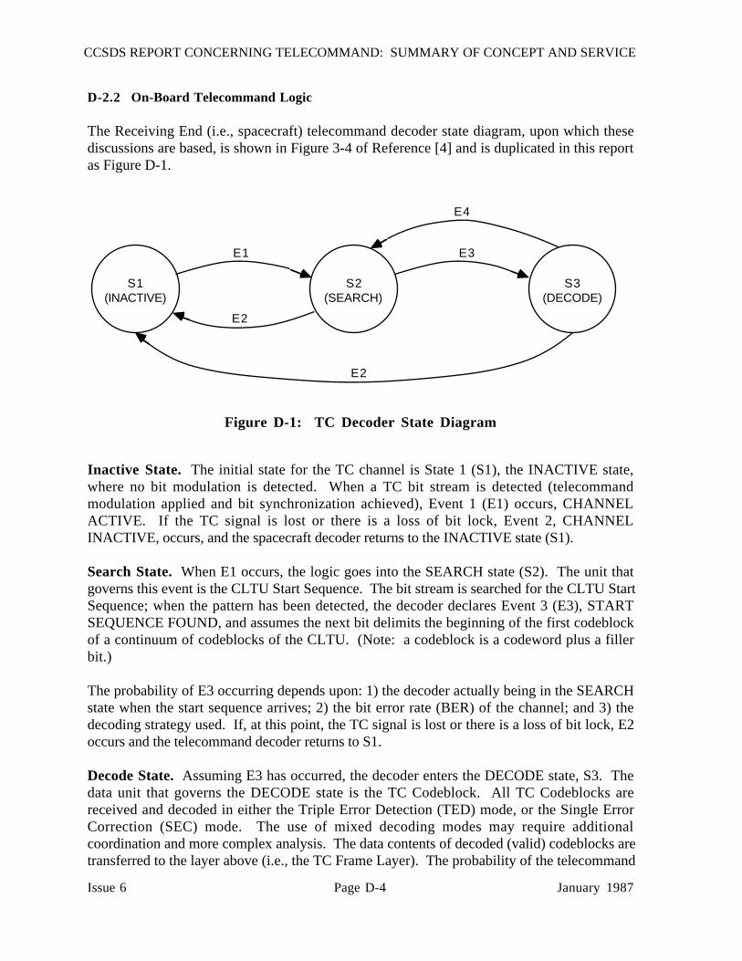
CCSDS REPORT CONCERNING TELECOMMAND: SUMMARY OF CONCEPT AND SERVICE
Issue 6 Page D-4 January 1987
D-2.2 On-Board Telecommand Logic
The Receiving End (i.e., spacecraft) telecommand decoder state diagram, upon which thesediscussions are based, is shown in Figure 3-4 of Reference [4] and is duplicated in this reportas Figure D-1.
S3(DECODE)
S2(SEARCH)
S1(INACTIVE)
E1
E2
E2
E3
E4
Figure D-1: TC Decoder State Diagram
Inactive State. The initial state for the TC channel is State 1 (S1), the INACTIVE state,where no bit modulation is detected. When a TC bit stream is detected (telecommandmodulation applied and bit synchronization achieved), Event 1 (E1) occurs, CHANNELACTIVE. If the TC signal is lost or there is a loss of bit lock, Event 2, CHANNELINACTIVE, occurs, and the spacecraft decoder returns to the INACTIVE state (S1).
Search State. When E1 occurs, the logic goes into the SEARCH state (S2). The unit thatgoverns this event is the CLTU Start Sequence. The bit stream is searched for the CLTU StartSequence; when the pattern has been detected, the decoder declares Event 3 (E3), STARTSEQUENCE FOUND, and assumes the next bit delimits the beginning of the first codeblockof a continuum of codeblocks of the CLTU. (Note: a codeblock is a codeword plus a fillerbit.)
The probability of E3 occurring depends upon: 1) the decoder actually being in the SEARCHstate when the start sequence arrives; 2) the bit error rate (BER) of the channel; and 3) thedecoding strategy used. If, at this point, the TC signal is lost or there is a loss of bit lock, E2occurs and the telecommand decoder returns to S1.
Decode State. Assuming E3 has occurred, the decoder enters the DECODE state, S3. Thedata unit that governs the DECODE state is the TC Codeblock. All TC Codeblocks arereceived and decoded in either the Triple Error Detection (TED) mode, or the Single ErrorCorrection (SEC) mode. The use of mixed decoding modes may require additionalcoordination and more complex analysis. The data contents of decoded (valid) codeblocks aretransferred to the layer above (i.e., the TC Frame Layer). The probability of the telecommand
CCSDS REPORT CONCERNING TELECOMMAND: SUMMARY OF CONCEPT AND SERVICE
Issue 6 Page D-5 January 1987
decoder remaining in this state is a function of the decoding strategy, the BER, the length of thecodeword (n), in bits, and the number of codewords in the CLTU.
Return from Decode State. If, during the decoding process, the decoder rejects acodeblock due to errors, no data from this codeblock are transferred to the layer above. Thissituation corresponds to Event 4 (E4), CODEBLOCK REJECTION, which returns the decoderto the SEARCH state (S2).
To end a CLTU, a Tail Sequence is included. The Tail Sequence is a codeblock (of the samelength as all other codeblocks in the stream) having a unique pattern constructed in such a wayto fail the decoder parity check and cause a CODEBLOCK REJECTION (E4), therebyinterrupting the telecommand continuum. No further codeblocks are decoded, no furthertransfer of codeblock contents to the frame layer is possible, and the decoder logic returns tothe SEARCH state (S2). Note that the ONLY function of the Tail Sequence is to force thedecoder logic to the SEARCH STATE at the end of a CLTU: the Tail Sequence should not beused to delimit the end of a frame. This is because, in general, 1) there may be more than oneframe in the CLTU, and 2) a frame that is not long enough to fill the last codeblock must befollowed by fill bits (which are not part of the frame) to complete that codeblock.
If, during the decoding process, the physical layer signal is lost (carrier, modulation or bitsync), event E2, CHANNEL INACTIVE, occurs. Upon this event, the decoder returns to theINACTIVE state, S1.
Assembling the Frame. If all codeblocks comprising a complete transfer frame aresuccessfully decoded, the frame layer recognizes that the frame it has been assembling fromeach codeblock is complete when the number of octets received equals one more than the countpresented in the "Frame Length" field of the Transfer Frame Header. The frame can then betransferred to the addressee. Other frames in the CLTU are similarly transferred uponcompletion. If the continuum of codeblocks from the decoder is interrupted (i.e.,CODEBLOCK REJECTION has been declared for whatever reason) and the frame lengthreceived does NOT yet equal one more than the count in the "Frame Length" field, that frame isrejected by the frame layer. Further action by the frame layer to recover the frame is dependenton the Command Operations Procedure (COP) in use. This process is more fully described inReference [3]. Other checks on the frame, such as testing for previously undetected errors,may also be made at the frame layer before declaring acceptance or rejection, and beforeforwarding to the addressee.
D-3 FACTORS AFFECTING FRAME REJECTION RATE
Each of the factors of performance of frame rejection rate are detailed below. In subsequentsections, the performance for several different CLTU organizations is given.

CCSDS REPORT CONCERNING TELECOMMAND: SUMMARY OF CONCEPT AND SERVICE
Issue 6 Page D-6 January 1987
D-3.1 Bit Synchronization Factor
Initially, the on-board decoder is in the INACTIVE state. When a signal first appears(subsequent to achieving rf carrier lock), it will contain an acquisition pattern consisting of aseries of alternating "ones" and "zeros". This pattern has the maximum transition density so asto provide the fastest lock-up time for the on-board bit synchronizer. The preferred length of128 bits was chosen to provide 0.9999 probability of acquisition of bit sync based onexperience with a number of hardware implementations operating at the command thresholdlevel.1 Clearly, this length may be modified as needed to suit different hardware characteristicsor channel bit error rates (such as, for example, a noise-free channel used during groundtesting). When bit synchronization has been achieved, the decoder leaves the INACTIVE stateand enters the SEARCH state.
BECAUSE THE PROBABILITY OF ACHIEVING BIT SYNCHRONIZATION ISPRIMARILY HARDWARE-DEPENDENT, THIS ANALYSIS WILL ASSUME THAT BITSYNCHRONIZATION HAS ALREADY BEEN ACHIEVED.
D-3.2 CLTU Start Sequence Factor
Once the on-board decoder is in the SEARCH state, it begins looking for the required CLTUStart Sequence. The Start Sequence provides two functions: 1) to resolve the ambiguitybetween a "one" and a "zero" if needed (e.g., when NRZ-L symbol representation is used),and 2) to delimit the beginning of the CLTU.
The Start Sequence is a fixed-pattern marker 16 bits long. It follows immediately after theacquisition sequence and before the first codeblock of the CLTU. As a consequence ofrecognizing the CLTU Start, the start of the first codeblock is then also delimited, since itimmediately follows the start sequence. In decoding serially transmitted block codes, it isusually necessary to know the point at which the block starts and its length. The codeblocklength which has been chosen for the mission must be known a priori, and must remainconstant.
Two operating strategies for recognizing the start sequence are presented in Reference [4]: Inthe first strategy (denoted by subscript A), the decoder requires that the entire 16 bits bereceived without error. In the second (denoted by subscript B), the decoder allows one of the16 bits to be in error and will still declare the start of a CLTU.
For the first strategy (that is, all 16 bits must be correct to declare a CLTU start) the probabilityof rejecting (missing) a CLTU start is found by simply taking the probability that one or morebit errors may fall on any of the 16 bits of the start sequence:
1 For example, the probability of the TDRSS transponder achieving bit lock in response tothis acquisition sequence is equal or greater than 0.9999.

CCSDS REPORT CONCERNING TELECOMMAND: SUMMARY OF CONCEPT AND SERVICE
Issue 6 Page D-7 January 1987
<Prob. of rejecting a START, no errors allowed> = PsA
= 1 - (1 - p)16 [EQ. A]
where p is the channel bit error rate.
For the second strategy (in which one bit error is allowed) it is necessary for TWO or more biterrors to appear in the start sequence before it will be rejected. In this case,
<Prob. of rejecting a START, 1 error allowed> = PsB
= 1 - [(1 - p)16 + 16p(1-p)15] [EQ. B]
These values are tabulated in Table D-1.
Table D-1: Probability of Rejection of CLTU Start Sequence(for case where no errors are allowed (PsA) andone error allowed (PsB))
________________________________________________________________
Channel Bit Error Rate
Case 10-4 10-5 10-6________________________________________________________________
PsA 1.60 x 10⁻³ 1.60 x 10⁻⁴ 160 x 10-5
PsB 1.20 x 10⁻⁶ 1.20 x 10⁻⁸ 1.20 x 10⁻¹⁰________________________________________________________________
PsA or PsB, above (depending on the strategy selected), constitutes the first factor of the overallframe rejection rate.
It should be noted that there is also the remote possibility that the proper start sequence may bemissed because of a false (premature) start. The start pattern was chosen for its property that itwould require at least 6 changed bits to declare such a premature start.
D-3.3 Codeblock Factor
Once CLTU Start has been recognized, the decoding process begins for the codeblocks thatfollow.

CCSDS REPORT CONCERNING TELECOMMAND: SUMMARY OF CONCEPT AND SERVICE
Issue 6 Page D-8 January 1987
The code specified in Reference [4] is a (63,56) BCH code. The codeword2 contains aninformation field of one of the lengths shown in Table D-2, followed by 7 parity bits. Tocomplete the codeblock (which, to meet general formatting rules for ease of handling, must bean integral number of octets), a single final fill bit set to "zero" is always appended to thecodeword. Normally, one TC codeblock length is selected for a mission, and all codeblocksare this length.
When decoding in the "Triple Error Detection" (TED) mode, the code has the property that itcan detect one-, two- or three-bit errors. Alternatively, when decoding in the "Single-Bit ErrorCorrection" (SEC) mode, it can correct one bit in error, and detect two bits in error within thecodeblock.
Decoding is performed by the Channel Service on a continuum basis. That is, as long as eachcodeblock is valid (after correction, if error correction is employed) the information content ofeach codeblock as it is accepted continues to be passed from the Coding layer to the Transferlayer where each frame is assembled. If a codeblock failure occurs, the continuum is broken;the decoder notifies the Transfer layer and ceases transferring any further data to it.
While 64 bits is the preferred codeblock length (because it allows minimum coding overhead toachieve the given performance), it is possible to shorten the codeblock while still using thesame coding algorithm. Permitted lengths for shortened codeblocks are 56, 48, and 40 bits,and are made possible by simply setting both encoder and decoder to assume the leadinguntransmitted octets of each codeblock are always "zero". This is called "virtual fill".
The permitted organizations of the codeblock, including the relationship between codeblocklength, virtual fill, information bits, parity bits, and fill bits, are shown below:
Table D-2: Codeblock Organization
___________________________________________________________________________Codeblock Virtual Codeword Information Parity Fill length, fill, length, bits (k) bits bit bits bits bits (n)
___________________________________________________________________________
64 0 63 56 7 1
56 8 55 48 7 1
48 16 47 40 7 1
40 24 39 32 7 1___________________________________________________________________________
2 "Codeword" refers to the code itself; for an (n,k) code, the codeword is always n bits long."Codeblock" as used here refers to the physical implementation in the bit stream andincludes the final fill bit. Codeblocks may be 40, 48, 56 or 64 bits in length.

CCSDS REPORT CONCERNING TELECOMMAND: SUMMARY OF CONCEPT AND SERVICE
Issue 6 Page D-9 January 1987
The equation characterizing codeblock rejection using TED mode is:
<Prob. of 1 or more codeblocksof the CLTU being detected asin error (using TED mode)> = PCA
= 1 - [1 - p)n]N [EQ. C]
wherep = channel bit error raten = number of bits in codeword (1 less than codeblock)N = number of codeblocks
For the SEC case, the equation for rejection of 1 or more codeblocks becomes:
<Prob. of 1 or more codeblock ofthe CLTU being in error ANDUNCORRECTABLE (SEC mode)> = PCB
= 1 - [(1-p)n + np(1-p)n-1]N [EQ. D]
Table D-3 provides values for both PCA and PCB for different numbers of 64-bit codeblocksfor the three different channel error rates, and these values are plotted in Figure D-2.
The codeblock factor is the second factor affecting frame rejection performance. Performanceis discussed next.
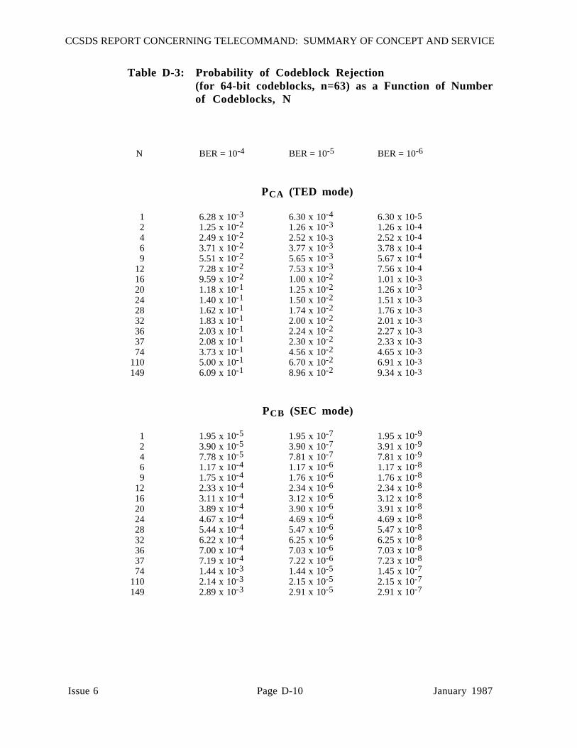
CCSDS REPORT CONCERNING TELECOMMAND: SUMMARY OF CONCEPT AND SERVICE
Issue 6 Page D-10 January 1987
Table D-3: Probability of Codeblock Rejection(for 64-bit codeblocks, n=63) as a Function of Numberof Codeblocks, N
N BER = 10-4 BER = 10-5 BER = 10-6
PCA (TED mode)
1 6.28 x 10⁻³ 6.30 x 10⁻⁴ 6.30 x 10-52 1.25 x 10⁻² 1.26 x 10⁻³ 1.26 x 10-44 2.49 x 10⁻² 2.52 x 10⁻³ 2.52 x 10-46 3.71 x 10⁻² 3.77 x 10⁻³ 3.78 x 10-49 5.51 x 10⁻² 5.65 x 10⁻³ 5.67 x 10⁻⁴
12 7.28 x 10⁻² 7.53 x 10⁻³ 7.56 x 10-416 9.59 x 10⁻² 1.00 x 10⁻² 1.01 x 10-320 1.18 x 10⁻¹ 1.25 x 10⁻² 1.26 x 10⁻³
24 1.40 x 10⁻¹ 1.50 x 10⁻² 1.51 x 10-328 1.62 x 10⁻¹ 1.74 x 10⁻² 1.76 x 10-332 1.83 x 10⁻¹ 2.00 x 10⁻² 2.01 x 10-336 2.03 x 10⁻¹ 2.24 x 10⁻² 2.27 x 10-337 2.08 x 10⁻¹ 2.30 x 10⁻² 2.33 x 10-374 3.73 x 10⁻¹ 4.56 x 10⁻² 4.65 x 10⁻³
110 5.00 x 10⁻¹ 6.70 x 10⁻² 6.91 x 10-3149 6.09 x 10⁻¹ 8.96 x 10⁻² 9.34 x 10⁻³
PCB (SEC mode)
1 1.95 x 10⁻⁵ 1.95 x 10⁻⁷ 1.95 x 10⁻⁹
2 3.90 x 10⁻⁵ 3.90 x 10⁻⁷ 3.91 x 10⁻⁹
4 7.78 x 10⁻⁵ 7.81 x 10⁻⁷ 7.81 x 10⁻⁹
6 1.17 x 10⁻⁴ 1.17 x 10⁻⁶ 1.17 x 10⁻⁸
9 1.75 x 10⁻⁴ 1.76 x 10⁻⁶ 1.76 x 10⁻⁸
12 2.33 x 10⁻⁴ 2.34 x 10⁻⁶ 2.34 x 10⁻⁸
16 3.11 x 10⁻⁴ 3.12 x 10⁻⁶ 3.12 x 10⁻⁸
20 3.89 x 10⁻⁴ 3.90 x 10⁻⁶ 3.91 x 10⁻⁸
24 4.67 x 10⁻⁴ 4.69 x 10⁻⁶ 4.69 x 10⁻⁸
28 5.44 x 10⁻⁴ 5.47 x 10⁻⁶ 5.47 x 10⁻⁸
32 6.22 x 10⁻⁴ 6.25 x 10⁻⁶ 6.25 x 10⁻⁸
36 7.00 x 10⁻⁴ 7.03 x 10⁻⁶ 7.03 x 10⁻⁸
37 7.19 x 10⁻⁴ 7.22 x 10⁻⁶ 7.23 x 10⁻⁸
74 1.44 x 10⁻³ 1.44 x 10⁻⁵ 1.45 x 10⁻⁷
110 2.14 x 10⁻³ 2.15 x 10⁻⁵ 2.15 x 10⁻⁷
149 2.89 x 10⁻³ 2.91 x 10⁻⁵ 2.91 x 10⁻⁷

CCSDS REPORT CONCERNING TELECOMMAND: SUMMARY OF CONCEPT AND SERVICE
Issue 6 Page D-11 January 1987
0 10 20 30 40 50 60
NUMBER OF CODEWORDS PER FRAME, N(BASED ON 64-BIT CODEBLOCKS)
10-9
10-8
10-7
10-6
10-5
10-4
10-3
10-2
10-1
10-0
PR
OB
AB
ILIT
Y O
F R
EJE
CT
ION
OF
ON
E O
R M
OR
E C
OD
EB
LOC
KS
BER = 10-5
BER = 10-4
BER = 10-6
BER = 10-5
BER = 10-4
BER = 10-6
P , USING
SECCB
P , , USINGTED
CA
Figure D-2: Probability of Rejection of One orMore Contiguous 64-Bit Codeblocksas a Function of Number ofCodeblocks, N

CCSDS REPORT CONCERNING TELECOMMAND: SUMMARY OF CONCEPT AND SERVICE
Issue 6 Page D-12 January 1987
D-4 FRAME REJECTION RATE: TYPICAL TC ORGANIZATIONS
The Telecommand Transfer Frame is the accounting entity for telecommand performance. Aframe may be any integral number of octets in length, from a minimum consisting of only aprimary header (5 octets or 40 bits) to the maximum number of octets that can be counted bythe "Frame Length" field in the header (256 octets or 2048 bits).
The TC Frame is serially inserted into the "information" fields of as many Codeblocks asnecessary. If the length of a frame is not exactly the same as the total data space of theInformation fields in the required codeblocks, fill is added to the Information field of only theLAST codeblock. If more than one frame resides in a CLTU, frames are organizedcontiguously and any necessary fill is added only in the LAST codeblock of the CLTU.
The necessary TC building blocks are the TC Frame, CLTU, and the codeblocks. These maybe organized in several different ways depending on the performance required, operationalconvenience, accounting convenience, etc. Three organizations are described below: Oneframe per CLTU; multiple frames per CLTU; and multiple CLTUs. Frame performance maybe assessed by considering the performance of a sequence of codeblocks and the effect of theirorganization into CLTUs.
D-4.1 One Frame, One CLTU
This section deals with the organization where each frame is contained in its own CLTU, asshown in Figure D-3. A codeblock rejection anywhere in the frame will cause rejection of thatframe.
ACQ P INFOSTART
INFO P PINFOTAIL
FRAME(CONTAINED IN INFO FIELDS)
CLTU
Figure D-3: Single Frame, Single CLTU Organization
The probability of frame rejection is determined from a) the probability of missing a CLTUstart, OR b) the probability of finding a CLTU start AND the probability of rejecting one ormore codeblocks.
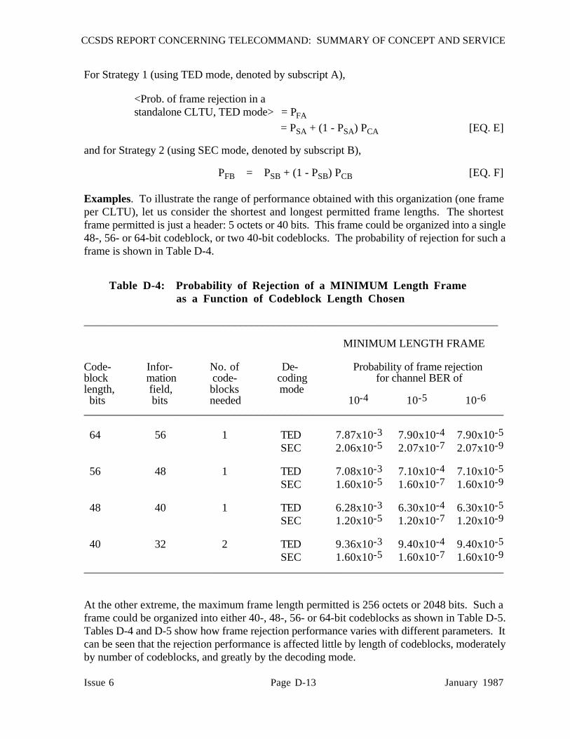
CCSDS REPORT CONCERNING TELECOMMAND: SUMMARY OF CONCEPT AND SERVICE
Issue 6 Page D-13 January 1987
For Strategy 1 (using TED mode, denoted by subscript A),
<Prob. of frame rejection in astandalone CLTU, TED mode> = PFA
= PSA + (1 - PSA) PCA [EQ. E]
and for Strategy 2 (using SEC mode, denoted by subscript B),
PFB = PSB + (1 - PSB) PCB [EQ. F]
Examples. To illustrate the range of performance obtained with this organization (one frameper CLTU), let us consider the shortest and longest permitted frame lengths. The shortestframe permitted is just a header: 5 octets or 40 bits. This frame could be organized into a single48-, 56- or 64-bit codeblock, or two 40-bit codeblocks. The probability of rejection for such aframe is shown in Table D-4.
Table D-4: Probability of Rejection of a MINIMUM Length Frameas a Function of Codeblock Length Chosen
__________________________________________________________________________
MINIMUM LENGTH FRAME
Code- Infor- No. of De- Probability of frame rejectionblock mation code- coding for channel BER oflength, field, blocks mode bits bits needed 10-4 10-5 10-6___________________________________________________________________________
64 56 1 TED 7.87x10⁻³ 7.90x10⁻⁴ 7.90x10⁻⁵
SEC 2.06x10⁻⁵ 2.07x10⁻⁷ 2.07x10⁻⁹
56 48 1 TED 7.08x10⁻³ 7.10x10⁻⁴ 7.10x10⁻⁵
SEC 1.60x10⁻⁵ 1.60x10⁻⁷ 1.60x10⁻⁹
48 40 1 TED 6.28x10⁻³ 6.30x10⁻⁴ 6.30x10⁻⁵
SEC 1.20x10⁻⁵ 1.20x10⁻⁷ 1.20x10⁻⁹
40 32 2 TED 9.36x10⁻³ 9.40x10⁻⁴ 9.40x10⁻⁵
SEC 1.60x10⁻⁵ 1.60x10⁻⁷ 1.60x10⁻⁹___________________________________________________________________________
At the other extreme, the maximum frame length permitted is 256 octets or 2048 bits. Such aframe could be organized into either 40-, 48-, 56- or 64-bit codeblocks as shown in Table D-5.Tables D-4 and D-5 show how frame rejection performance varies with different parameters. Itcan be seen that the rejection performance is affected little by length of codeblocks, moderatelyby number of codeblocks, and greatly by the decoding mode.
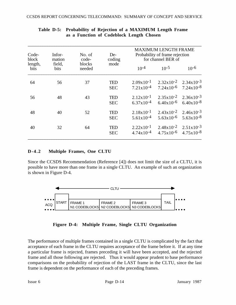
CCSDS REPORT CONCERNING TELECOMMAND: SUMMARY OF CONCEPT AND SERVICE
Issue 6 Page D-14 January 1987
Table D-5: Probability of Rejection of a MAXIMUM Length Frameas a Function of Codeblock Length Chosen
___________________________________________________________________________ MAXIMUM LENGTH FRAME
Code- Infor- No. of De- Probability of frame rejectionblock mation code- coding for channel BER oflength, field, blocks mode bits bits needed 10-4 10-5 10-6___________________________________________________________________________
64 56 37 TED 2.09x10⁻¹ 2.32x10⁻² 2.34x10⁻³
SEC 7.21x10⁻⁴ 7.24x10⁻⁶ 7.24x10⁻⁸
56 48 43 TED 2.12x10⁻¹ 2.35x10⁻² 2.36x10⁻³
SEC 6.37x10⁻⁴ 6.40x10⁻⁶ 6.40x10⁻⁸
48 40 52 TED 2.18x10⁻¹ 2.43x10⁻² 2.46x10⁻³
SEC 5.61x10⁻⁴ 5.63x10⁻⁶ 5.63x10⁻⁸
40 32 64 TED 2.22x10⁻¹ 2.48x10⁻² 2.51x10⁻³
SEC 4.74x10⁻⁴ 4.75x10⁻⁶ 4.75x10⁻⁸___________________________________________________________________________
D-4.2 Multiple Frames, One CLTU
Since the CCSDS Recommendation (Reference [4]) does not limit the size of a CLTU, it ispossible to have more than one frame in a single CLTU. An example of such an organizationis shown in Figure D-4.
ACQSTART TAIL
CLTU
FRAME 1N1 CODEBLOCKS
FRAME 2N2 CODEBLOCKS
FRAME 3N3 CODEBLOCKS
Figure D-4: Multiple Frame, Single CLTU Organization
The performance of multiple frames contained in a single CLTU is complicated by the fact thatacceptance of each frame in the CLTU requires acceptance of the frame before it. If at any timea particular frame is rejected, frames preceding it will have been accepted, and the rejectedframe and all those following are rejected. Thus it would appear prudent to base performancecomparisons on the probability of rejection of the LAST frame in the CLTU, since the lastframe is dependent on the performance of each of the preceding frames.
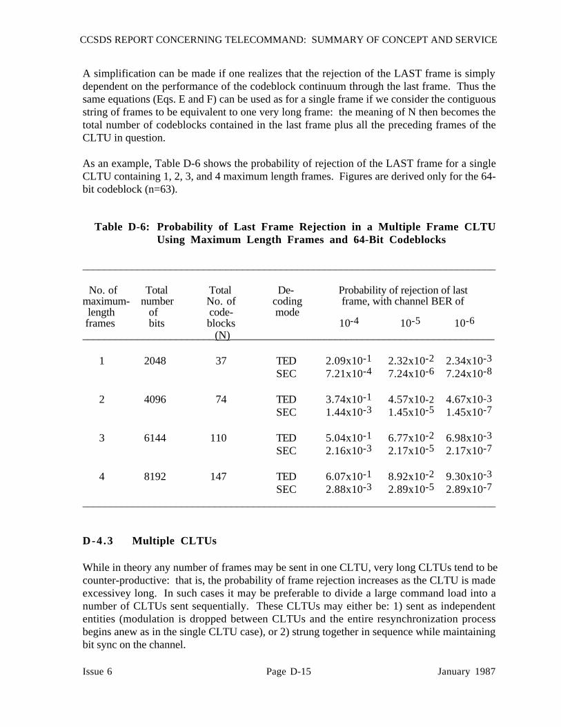
CCSDS REPORT CONCERNING TELECOMMAND: SUMMARY OF CONCEPT AND SERVICE
Issue 6 Page D-15 January 1987
A simplification can be made if one realizes that the rejection of the LAST frame is simplydependent on the performance of the codeblock continuum through the last frame. Thus thesame equations (Eqs. E and F) can be used as for a single frame if we consider the contiguousstring of frames to be equivalent to one very long frame: the meaning of N then becomes thetotal number of codeblocks contained in the last frame plus all the preceding frames of theCLTU in question.
As an example, Table D-6 shows the probability of rejection of the LAST frame for a singleCLTU containing 1, 2, 3, and 4 maximum length frames. Figures are derived only for the 64-bit codeblock (n=63).
Table D-6: Probability of Last Frame Rejection in a Multiple Frame CLTUUsing Maximum Length Frames and 64-Bit Codeblocks
___________________________________________________________________________
No. of Total Total De- Probability of rejection of lastmaximum- number No. of coding frame, with channel BER of length of code- mode frames bits blocks 10-4 10-5 10-6
________________________(N)________________________________________________
1 2048 37 TED 2.09x10⁻¹ 2.32x10⁻² 2.34x10⁻³
SEC 7.21x10⁻⁴ 7.24x10⁻⁶ 7.24x10⁻⁸
2 4096 74 TED 3.74x10⁻¹ 4.57x10⁻² 4.67x10⁻³SEC 1.44x10⁻³ 1.45x10⁻⁵ 1.45x10⁻⁷
3 6144 110 TED 5.04x10⁻¹ 6.77x10⁻² 6.98x10⁻³
SEC 2.16x10⁻³ 2.17x10⁻⁵ 2.17x10⁻⁷
4 8192 147 TED 6.07x10⁻¹ 8.92x10⁻² 9.30x10⁻³
SEC 2.88x10⁻³ 2.89x10⁻⁵ 2.89x10⁻⁷
___________________________________________________________________________
D-4.3 Multiple CLTUs
While in theory any number of frames may be sent in one CLTU, very long CLTUs tend to becounter-productive: that is, the probability of frame rejection increases as the CLTU is madeexcessivey long. In such cases it may be preferable to divide a large command load into anumber of CLTUs sent sequentially. These CLTUs may either be: 1) sent as independententities (modulation is dropped between CLTUs and the entire resynchronization processbegins anew as in the single CLTU case), or 2) strung together in sequence while maintainingbit sync on the channel.

CCSDS REPORT CONCERNING TELECOMMAND: SUMMARY OF CONCEPT AND SERVICE
Issue 6 Page D-16 January 1987
If CLTUs are separated by dropping modulation, each CLTU will perform as an independententity and may be analyzed as shown in Sections D-4.1 or D-4.2. However, if the CLTUs arestrung together tail-to-start with an uninterrupted bit stream as shown in Figure D-5, somefurther considerations are necessary.
ACQ PSTART
INFO INFO P
CLTU 2
FRAME 1 FRAME 2
TAILP INFOINFO P
TAILSTARTINFO P
CLTU 1
Figure D-5: Multiple Frame CLTU Organization (Contiguous CLTUs)
With this organization, the CLTU Tail Sequence becomes important, since the Tail Sequencemust be relied upon to declare a CODEBLOCK REJECTION and force the decoder intoSEARCH STATE at the end of each CLTU. ONLY IF THE DECODER IS IN SEARCHSTATE WILL IT BE ABLE TO RECOGNIZE THE START SEQUENCE OF THE NEXTCLTU.
The decoder enters SEARCH state when a CODEBLOCK REJECTION is encountered (in thiscase caused by the tail sequence.) However, it is possible for the decoder to "miss" a tailsequence (i.e., the intended function, CODEBLOCK REJECTION, does not occur). Such acondition could happen if bit errors on the channel suitably change the tail sequence to make itan apparently valid codeblock, or (in SEC mode) make it appear (wrongly) to be correctable.This requires the received tail sequence to have at least 2 introduced bit changes in the TEDmode, or 1 introduced bit change in the SEC mode.
Upon missing a tail sequence, the decoder remains in DECODE state after the first CLTU's tailand cannot recognize the next CLTU's START sequence which follows immediately.Although the Start Sequence of the next CLTU is NOT part of a codeblock and so has a highprobability of causing CODEBLOCK REJECTION, this attribute is of no help at this point,since the start sequence has already passed. As a result, the entire CLTU which follows ismissed.
The probability of missing a tail sequence when using the TED decoding mode is theprobability that 2 or more changes are introduced into the tail sequence during transmission:
PTA = 1 - [(1 - p)n + np(1 - p)n-1] [EQ. G]
where n = length of tail sequence in bits.

CCSDS REPORT CONCERNING TELECOMMAND: SUMMARY OF CONCEPT AND SERVICE
Issue 6 Page D-17 January 1987
The probability of missing a tail sequence when using the SEC decoding mode is theprobability that one or more changes are introduced into the tail sequence during transmission:
PTB = 1 - (1 - p)n [EQ. H]
It should be noted that Equations G and H are conservative approximations, since changes incertain locations may not result in a missed tail. Values are tabulated in Table D-7.
Table D-7: Probability of Missing Tail Sequence, PTA (TED) and PTB (SEC)___________________________________________________________________________
Probability of missing a tail,Tail Sequence Decoding for a Channel BER of length, bits mode 10-4 10-5 10-6___________________________________________________________________________
64 TED (PTA) 1.95x10⁻⁵ 1.95x10⁻⁷ 1.95x10⁻⁹
SEC (PTB) 6.28x10⁻³ 6.30x10⁻⁴ 6.30x10⁻⁵
56 TED (PTA) 1.48x10⁻⁵ 1.48x10⁻⁷ 1.48x10⁻⁹
SEC (PTB) 5.49x10⁻³ 5.50x10⁻⁴ 5.50x10⁻⁵
48 TED (PTA) 1.08x10⁻⁵ 1.08x10⁻⁷ 1.08x10⁻⁹
SEC (PTB) 4.69x10⁻³ 4.70x10⁻⁴ 4.70x10⁻⁵
40 TED (PTA) 7.39x10⁻⁶ 7.41x10⁻⁸ 7.41x10⁻¹⁰
SEC (PTB) 3.89x10⁻³ 3.90x10⁻⁴ 3.90x10⁻⁵___________________________________________________________________________
The probability of rejection of the last frame in a CLTU which follows another CLTU (withoutreacquisition) may be evaluated as the probability of missing the tail of the preceding CLTU(PTA or PTB) OR the probability of rejecting the last frame of the subject CLTU.
That is,
<Prob. of frame rejection insubsequent CLTU, TED decoding> = PF2A
= PTA + (1-PTA)PFA
= PTA + (1-PTA)[(PSA + (1-PSA)PCA] [EQ. I]
where PFA refers to the frame performance as previously calculated in Equation E (independentof a previous CLTU); and
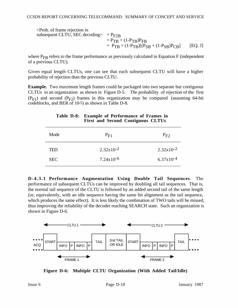
CCSDS REPORT CONCERNING TELECOMMAND: SUMMARY OF CONCEPT AND SERVICE
Issue 6 Page D-18 January 1987
<Prob. of frame rejection insubsequent CLTU, SEC decoding> = PF2B
= PTB + (1-PTB)PFB= PTB + (1-PTB)[(PSB + (1-PSB)PCB] [EQ. J]
where PFB refers to the frame performance as previously calculated in Equation F (independentof a previous CLTU).
Given equal length CLTUs, one can see that each subsequent CLTU will have a higherprobability of rejection than the previous CLTU.
Example. Two maximum length frames could be packaged into two separate but contiguousCLTUs in an organization as shown in Figure D-5. The probability of rejection of the first(PF1) and second (PF2) frames in this organization may be compared (assuming 64-bitcodeblocks, and BER of 10-5) as shown in Table D-8.
Table D-8: Example of Performance of Frames inFirst and Second Contiguous CLTUs
__________________________________________________________
Mode PF1 PF2__________________________________________________________
TED 2.32x10⁻² 2.32x10⁻²
SEC 7.24x10⁻⁶ 6.37x10⁻⁴__________________________________________________________
D-4 .3 .1 Performance Augmentation Using Double Tail Sequences. Theperformance of subsequent CLTUs can be improved by doubling all tail sequences. That is,the normal tail sequence of the CLTU is followed by an added second tail of the same length(or, equivalently, with an idle sequence having the same bit alignment as the tail sequence,which produces the same effect). It is less likely the combination of TWO tails will be missed,thus improving the reliability of the decoder reaching SEARCH state. Such an organization isshown in Figure D-6.
TAILACQ P INFO
STARTINFO P P INFO
STARTINFO P
TAIL2nd TAILOR IDLE
CLTU 1 CLTU 2
FRAME 1 FRAME 2
Figure D-6: Multiple CLTU Organization (With Added Tail/Idle)

CCSDS REPORT CONCERNING TELECOMMAND: SUMMARY OF CONCEPT AND SERVICE
Issue 6 Page D-19 January 1987
With this organization, the probability of missing both tails is the probability of missing thefirst one AND the probability of missing the second; that is,
<Prob. of missing a double tailsequence, using TED decoding> = PTAD
= (PTA)2 [EQ. K]
and
<Prob. of missing a double tailsequence, using SEC decoding> = PTBD
= (PTB)2 [EQ. L]
With double tails, the probabilities of missing a tail shown in Table D-7 take on the new valuesshown in Table D-9.
Table D-9: Probability of Missing DOUBLE Tail Sequence,PTAD (TED) and PTBD (SEC)
___________________________________________________________________________
Probability of missing a double tail, for a Channel BER of
Tail Sequence Decoding length, bits Mode 10-4 10-5 10-6
___________________________________________________________________________
64 TED (PTAD ) 3.78x10⁻¹⁰ 3.81x10⁻¹⁴ 3.81x10⁻¹⁸
SEC (PTBD ) 3.94x10⁻⁵ 3.97x10⁻⁷ 3.97x10⁻⁹
56 TED (PTAD ) 2.19x10⁻¹⁰ 2.20x10⁻¹⁴ 2.21x10⁻¹⁸
SEC (PTBD ) 3.01x10⁻⁵ 3.02x10⁻⁷ 3.02x10⁻⁹
48 TED (PTAD ) 1.16x10⁻¹⁰ 1.17x10⁻¹⁴ 1.17x10⁻¹⁸SEC (PTBD ) 2.20x10⁻⁵ 2.21x10⁻⁷ 2.21x10⁻⁹
40 TED (PTAD ) 5.46x10⁻¹¹ 5.49x10⁻¹⁵ 5.49x10⁻¹⁹
SEC (PTBD ) 1.52x10⁻⁵ 1.52x10⁻⁷ 1.52x10⁻⁹
___________________________________________________________________________

CCSDS REPORT CONCERNING TELECOMMAND: SUMMARY OF CONCEPT AND SERVICE
Issue 6 Page D-20 January 1987
Example. If we take the example above of two maximum-length frames in separate butcontiguous CLTUs (Table D-8) and use double tail sequences between the CLTUs (assuming64-bit codeblocks and channel BER of 10-5), the probability of rejection of the first and secondframes is shown in Table D-10.
Table D-10: Example of Performance of Frames in First andSecond Contiguous CLTUs Using DOUBLE TailSequences Between CLTUs
____________________________________________________________
Mode PF1 PF2____________________________________________________________
TED 2.32x10⁻² 2.32x10⁻²
SEC 7.24x10⁻⁶ 7.63x10⁻⁶____________________________________________________________
D-4 .3 .2 Performance Augmentation Using Fill Bit. When using the SEC decodingmode (single bit error correction/double bit error detection), a single bit error in reception of anormal codeword will be corrected, making the codeblock acceptable. The followingdiscussion only applies when using the SEC decoding mode where such corrections arepossible. The tail sequence is not a codeword but is instead a specially constructed sequencedesigned to appear to the decoder as an "uncorrectable pattern". This means that when the tailsequence is received without change, the decoder will declare that the received sequence is anuncorrectable pattern, which forces it to leave the DECODE state and enter the SEARCH state.
However, if a single bit of this tail sequence becomes altered in the channel, the receivedsequence may no longer be recognized as "uncorrectable", and an improper correction may takeplace. Because the expected CODEBLOCK REJECTION did not occur, we say the tailsequence was "missed" (not recognized). The probability of this happening is given byEquation H.
Missing a tail sequence has far-reaching effects, since it is possible that the decoder will not bein SEARCH state for the next CLTU and therefore the entire subsequent CLTU may bemissed.
This problem may be significantly reduced and the reliability of identifying a tail sequenceimproved by using the fill bit to selectively inhibit the SEC mode. As described in Reference[4], each valid codeblock terminates on a fill bit which is always set to "0". A tail sequence(which consists of an alternating pattern of ones and zeros starting with a zero) will alwayscontain a "1" in the position normally occupied by the fill bit in a regular codeblock. Thisinformation can be exploited at the receiving end to inhibit the SEC mode whenever the fill bitis a "one". This process substantially improves the ability to identify a tail sequence with anegligible effect on the codeword acceptance process.

CCSDS REPORT CONCERNING TELECOMMAND: SUMMARY OF CONCEPT AND SERVICE
Issue 6 Page D-21 January 1987
The recommended algorithm at the receiving end is as follows:
(1) Test the received pattern alone (ignoring the fill bit) for errors.
(2) If NO errors are detected in the received pattern, ACCEPT the codeword andIGNORE the fill bit.
(3) If ONE error is detected in the received pattern, TEST the fill bit.
(a) If the fill bit = 0, correct the error in the pattern and ACCEPT it.
(b) If the fill bit = 1, declare a CODEBLOCK REJECTION.
(4) If TWO errors are detected in the received pattern, declare a CODEBLOCKREJECTION. IGNORE the fill bit.
By selectively testing the fill bit, the probability of missing a tail sequence can be found fromthe probability of a single bit being changed in any portion of the tail sequence except the fillbit, AND that the received fill bit has also been changed. That is, TWO changes have to occurin the same codeblock, one of which must be the fill bit position.
<Prob. of missing a tail
sequence using fill bit test> = PTBF= [1 - (1 - p)n]p [EQ. M]
Comparing this with Equation H, one can see that the probability of missing a tail sequence hasnow been reduced by several orders of magnitude (i.e., by the bit error rate, p.) Values aregiven in Table D-11.
Table D-11. Probability of Missing a Tail Sequence, PTBF, Using the Fill BitAlgorithm (SEC Decoding Mode Only)
___________________________________________________________________________
Probability of missing tail sequence Codeblock n, for channel BER oflength, bits bits 10-4 10-5 10-6___________________________________________________________________________
64 63 6.26x10⁻⁷ 6.30x10⁻⁹ 6.30x10⁻¹¹
56 55 5.47x10⁻⁷ 5.50x10⁻⁹ 5.50x10⁻¹¹
48 47 4.68x10⁻⁷ 4.70x10⁻⁹ 4.70x10⁻¹¹
40 39 3.89x10⁻⁷ 3.90x10⁻⁹ 3.90x10⁻¹¹___________________________________________________________________________

CCSDS REPORT CONCERNING TELECOMMAND: SUMMARY OF CONCEPT AND SERVICE
Issue 6 Page D-22 January 1987
It should be noted that while this technique substantially reduces the likelihood of missing a tailsequence, there is a penalty in the form of a slight increase in frame rejection rate. That is, acodeblock containing one error which would normally be corrected and accepted may (butrarely) also have an error in its fill bit. If this algorithm were not used, the erroneous fill bitwould not be tested and the codeblock would be accepted. Under this algorithm, such acodeblock would be rejected even though the information was correctable. The equation forcodeblock rejection (PCB, Equation D) must be modified to account for testing the fill bit (asshown for PCBF, Equation N) but the effect on codeblock rejection is very slight:
<Prob. of codeblock rejection,
SEC mode and using fill bit test> = PCBF (fill bit test)
= 1 - [(1-p)n + (1-p)np(1-p)n-1]N [EQ. N]
Frame rejection performance for the frame in the second CLTU is then:
<Prob. of last frame rejectionin subsequent CLTU,using SEC decodingand the fill bit algorithm> = PF2BF
= PTBF + (1-PTBF)PFBF [EQ. O]
where
PTBF = prob. of missing tail when using fill bit test (Equation M)
PFBF = PSB + (1 - PSB)PCBF
and
PCBF = prob. of codeblock rejection when using fill bit test (Equation N)
Example. The probability of frame rejection for the example of two maximum-length framesorganized into separate CLTUs (as shown in Figure D-5) using SEC decoding mode, 64-bitcodeblocks, channel BER of 10-5 and the fill bit algorithm is shown in Table D-12.
Table D-12: Example of Performance of Frames in First andSecond Contiguous CLTUs Using Fill Bit Algorithm
_______________________________________________________
Mode PF1 PF2_______________________________________________________
SEC 7.47x10⁻⁶ 7.47x10⁻⁶_______________________________________________________

CCSDS REPORT CONCERNING TELECOMMAND: SUMMARY OF CONCEPT AND SERVICE
Issue 6 Page D-23 January 1987
D-5 UNDETECTED ERROR PERFORMANCE
The second performance requirement deals with undetected error, and requires that theprobability of accepting a frame with an undetected error is greater than 10-9. Again, the unitof accountability is the frame.
Often the methods used to improve frame rejection rate (such as SEC) cause reducedperformance on undetected errors, and vice versa. Therefore an acceptable balance must befound between these two objectives. Reference [8] shows that the required undetected errorperformance will be met by the prescribed system using either TED or SEC decoding in achannel operating at a BER of 10-5 without extra precautions. However, if a greater margin ofsafety against undetected errors is desired, the cyclic redundancy code specified in Reference[8] may be added to each frame. For an overhead of 16 bits per frame and the same channelBER of 10-5, this will provide an undetected frame error rate of 10-19 when using SECdecoding; with TED decoding, the performance is better. Figure D-7 shows curves comparingundetected error performance (with and without the added CRC) as a function of number ofcodeblocks in a frame for channel BER of 10-5. These curves are from Reference [8].

CCSDS REPORT CONCERNING TELECOMMAND: SUMMARY OF CONCEPT AND SERVICE
Issue 6 Page D-24 January 1987
0 10 20 30 40 50 60
NUMBER OF CODEBLOCKS PER FRAME
10-22
10-21
10-20
10-19
10-16
10-15
10-14
10-11
10-10
10-09
PR
OB
AB
ILIT
Y O
F U
ND
ET
EC
TE
D F
RA
ME
ER
RO
R BCH CODEBLOCKSALONE
(SEC DECODING)
(TED DECODING)
BCH CODEBLOCKSCONCATENATEDWITH FRAME CRC(SEC DECODING)
Figure D-7: Undetected Error Performance, With andWithout Cyclic Redundancy Code
END OF DOCUMENT. o


![Telecommand and Telemetry Implementation of Aalto-2 ...Marc Justicia] Telecommand and...Aalto-1 is the first Finnish satellite that will reach space by the end of 2016. It is built](https://static.fdocuments.us/doc/165x107/5e272a140c1db637d1463fd4/telecommand-and-telemetry-implementation-of-aalto-2-marc-justicia-telecommand.jpg)