Report Ref. No. 68.290.14.052...Yangzhou Opto-Electrical Products Testing Institute No.10 West Kaifa...
17
Transcript of Report Ref. No. 68.290.14.052...Yangzhou Opto-Electrical Products Testing Institute No.10 West Kaifa...

Page 2 of 17 Report Ref. No. 68.290.14.052.01
Test Report TUV_59020A:2013 Rev. 00
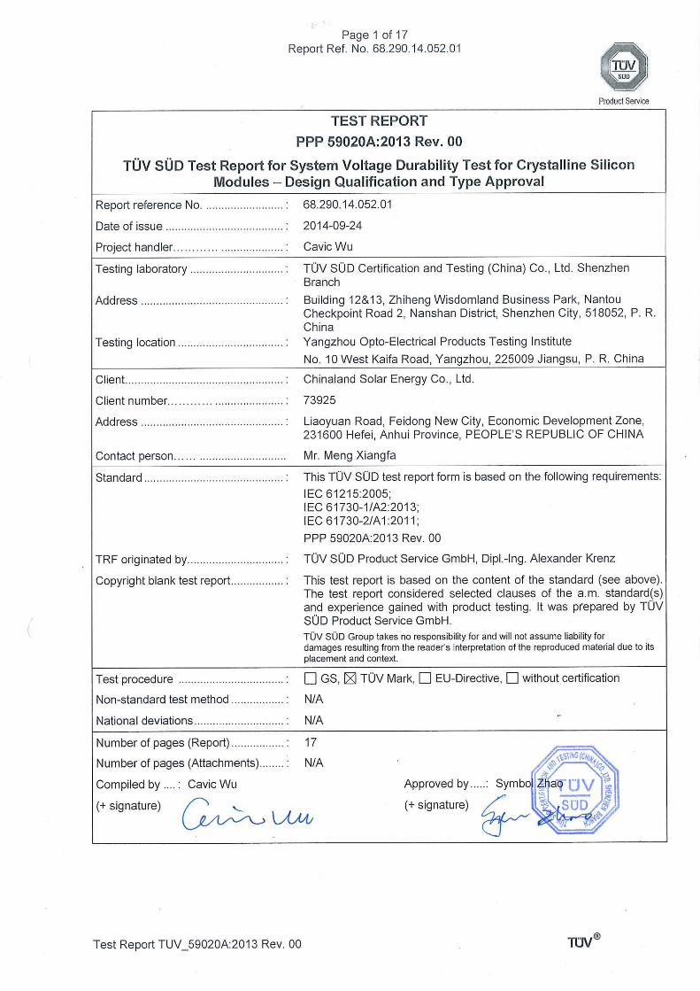
Test sample…………………………....: CHN245-60P
Type of test object .............................. : Poly-crystalline Silicon Photovoltaic Module
Trademark ........................................... :
Model and/or type reference .............. : a) 72 cells: CHN285-72P, CHN290-72P, CHN295-72P, CHN300-72P, CHN305-72P, CHN310-72P, CHN315-72P;
b) 60 cells: CHN235-60P, CHN240-60P, CHN245-60P, CHN250-60P, CHN255-60P, CHN260-60P, CHN265-60P;
c) 54 cells: CHN210-54P, CHN215-54P, CHN220-54P, CHN225-54P, CHN230-54P, CHN235-54P;
Rating(s).............................................. : Rated Output Power at STC:
a) 285 W, 290 W, 295 W, 300 W, 305 W, 310 W, 315 W
b) 235 W, 240 W, 245 W, 250 W, 255 W, 260 W, 265 W
c) 210 W, 215 W, 220 W, 225 W, 230 W, 235 W
Manufacturer ....................................... : Chinaland Solar Energy Co., Ltd.
Manufacturer number… ..................... : 73925
Address ............................................... : Liaoyuan Road, Feidong New City, Economic Development Zone, 231600 Hefei, Anhui Province, PEOPLE’S REPUBLIC OF CHINA
Sub-contractors/ tests (clause) .......... : See under summary of testing, page 3
Name ................................................... : See under summary of testing, page 3
Order description… ............................ : Complete test according to TRF
Partial test according to manufacturer's specifications
Preliminary test
Spot check
Date of order……… ............................ : 2014-07-23
Date of receipt of test item ................. : 2014-08-28
Date(s) of performance of test ........... : 2014-08-29 ~ 2014-09-03
Test item particulars:
The system voltage durability test according to PPP 59020A were performed on samples CHN245-60P, and the test results were positive.
Attachments: N/A

Page 3 of 17 Report Ref. No. 68.290.14.052.01
Test Report TUV_59020A:2013 Rev. 00
Summary of testing:
Tests performed (name of test and test clause):
Initial measurements:
6.1) Preconditioning
6.2) MST 01: Visual inspection
6.3) 10.2: Maximum power determination
6.4) 10.3 insulation test
6.5) MST 13: Ground continuity test
6.6) Damp heat test applied with voltage stress
in accordance with IEC 60068-2-78
Final measurements:
6.7) 10.15: Wet leakage current test
6.8) 10.2: Maximum power determination
6.9) MST 01: Visual inspection
6.10) 10.3 insulation test
Testing location:
Yangzhou Opto-Electrical Products Testing Institute
No.10 West Kaifa Road, Yangzhou, 225009 Jiangsu, P. R. China
Summary of compliance with National Differences: N/A
Copy of marking plate:

Page 4 of 17 Report Ref. No. 68.290.14.052.01
Test Report TUV_59020A:2013 Rev. 00
Test item particulars .................................................. :
Accessories and detachable parts included in the evaluation ...................................................................... :
N/A
Option included ............................................................. : N/A
Possible test case verdicts:
- test case does not apply to the test object ................ : N/A
- test object does meet the requirement ...................... : P (Pass)
- test object does not meet the requirement ................ : F (Fail)
Abbreviations used in the report:
STC – Standard Test Conditions Vmp – Maximum power voltage
Imp – Maximum power current Voc – Open circuit voltage
Isc – Short circuit current Pmp – Maximum power
General remarks:
The test results presented in this report relate only to the object tested. This report shall not be reproduced, except in full, without the written approval of the Issuing testing laboratory. "(see Enclosure #)" refers to additional information appended to the report. "(see appended table)" refers to a table appended to the report. Throughout this report a point is used as the decimal separator. Summary of contents provided on the last page of this report.
Factory: Chinaland Solar Energy Co., Ltd.
Address: Liaoyuan Road, Feidong New City, Economic Development Zone, 231600 Hefei, Anhui Province, PEOPLE’S REPUBLIC OF CHINA
General product information and considerations:
Product Electrical Ratings:
Type or model number CHN245-60P
Voc (Vdc) 36.1
Isc (Adc) 8.63
Vmp (Vdc) 30.4
Imp (Adc) 8.05
Pmp (W) 245
Deviation of Pmp at STC ±5%
Maximum system voltage (V) 1000
Maximum over-current protection rating (A) 15
Application Class A
Information for testing sample:
Sample # Type Series number
1 CHN245-60P CHN1408880010
2 CHN245-60P CHN1408880013
3 CHN245-60P CHN1408880016
4 CHN245-60P CHN1408880011
5 CHN245-60P CHN1408880012

Page 5 of 17 Report Ref. No. 68.290.14.052.01
Test Report TUV_59020A:2013 Rev. 00
Description of module construction:(Manufactories and part numbers, unless otherwise specified)
Sample.............................................: Random sampling from productionPrototype submitted by client
Module CHN245-60P
Front Cover......................................: Material: Tempered glass, thickness: 3.2 mm
Nanjing Solglass Science & technology Co., Ltd.
Rear Cover ......................................: Type: FPE350Cw, Color: White, material: PVDF/Adhesive/PET/
Adhesive/PE, thickness: 20/5/250/5/60 (µm), Max. voltage: 1057 V
Lucky Film Co., LTD.
Encapsulation material ....................: Material: EVA , Type:HBL9160D-905(glass side)+ HBL9160D-709(substrate side), combined use only
Nanjing Hongbaoli New Materials Co., Ltd.
Frame ..............................................: Type : 6063-T5, Material: Anodized aluminum
Zhang Jia Gang Da Yang Aluminum Industry CO.,LTD.
Dimensions (l x w x h) [mm] ............: 1640x990x35
Module area [m²] .............................: 1.62
Adhesives (junction box) .................: Type : MH-3668, Color: White, RTI: 105°C
Jiangsu MingHao New Mstar Technology Ltd
Minimum distance between current-carrying parts and module edge [mm]
14
Cell
Cell (include type) ............................: Poly c-Si
Cells (l x w) [mm] .............................: 156x156
Cell thickness [µm] ..........................: 200±20
Cell area [cm²] .................................: 243.36
Number of cells................................: 60
Components
Cells per bypass diode ....................: 20
Type of bypass diode ......................: Schottky, Type: THY2550
PanJit International Inc.
No. of bypass diodes ......................: 3
Cell- and string connectors..............: Tin-coated copper ribbon, Material: Sn63Pb37
For cell interconnector: Cross section: 0.25 x 1.6 (mm), For string connector: Cross section: 0.35 x 6.0 (mm)
Baoding Yitong PV Science & Technology Co., Ltd.
Junction box ....................................: Type : PV-JM805A, 1000V DC, 15A, -40 to +85°C, IP67
Page 6 of 17 Report Ref. No. 68.290.14.052.01
Test Report TUV_59020A:2013 Rev. 00
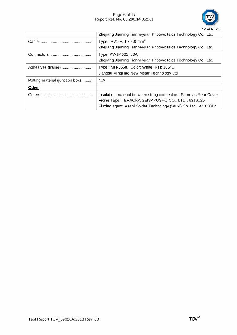
Zhejiang Jiaming Tianheyuan Photovoltaics Technology Co., Ltd.
Cable ............................................... : Type : PV1-F, 1 x 4.0 mm2
Zhejiang Jiaming Tianheyuan Photovoltaics Technology Co., Ltd.
Connectors ...................................... : Type: PV-JM601, 30A
Zhejiang Jiaming Tianheyuan Photovoltaics Technology Co., Ltd.
Adhesives (frame) ........................... : Type : MH-3668, Color: White, RTI: 105°C
Jiangsu MingHao New Mstar Technology Ltd
Potting material (junction box) ......... : N/A
Other
Others .............................................. : Insulation material between string connectors: Same as Rear Cover
Fixing Tape: TERAOKA SEISAKUSHO CO., LTD., 631S#25
Fluxing agent: Asahi Solder Technology (Wuxi) Co. Ltd., ANX3012
Page 7 of 17 Report Ref. No. 68.290.14.052.01
PPP 59020A
Clause Requirement + Test Result--Remark Verdict
Test Report TUV_59020A:2013 Rev. 00
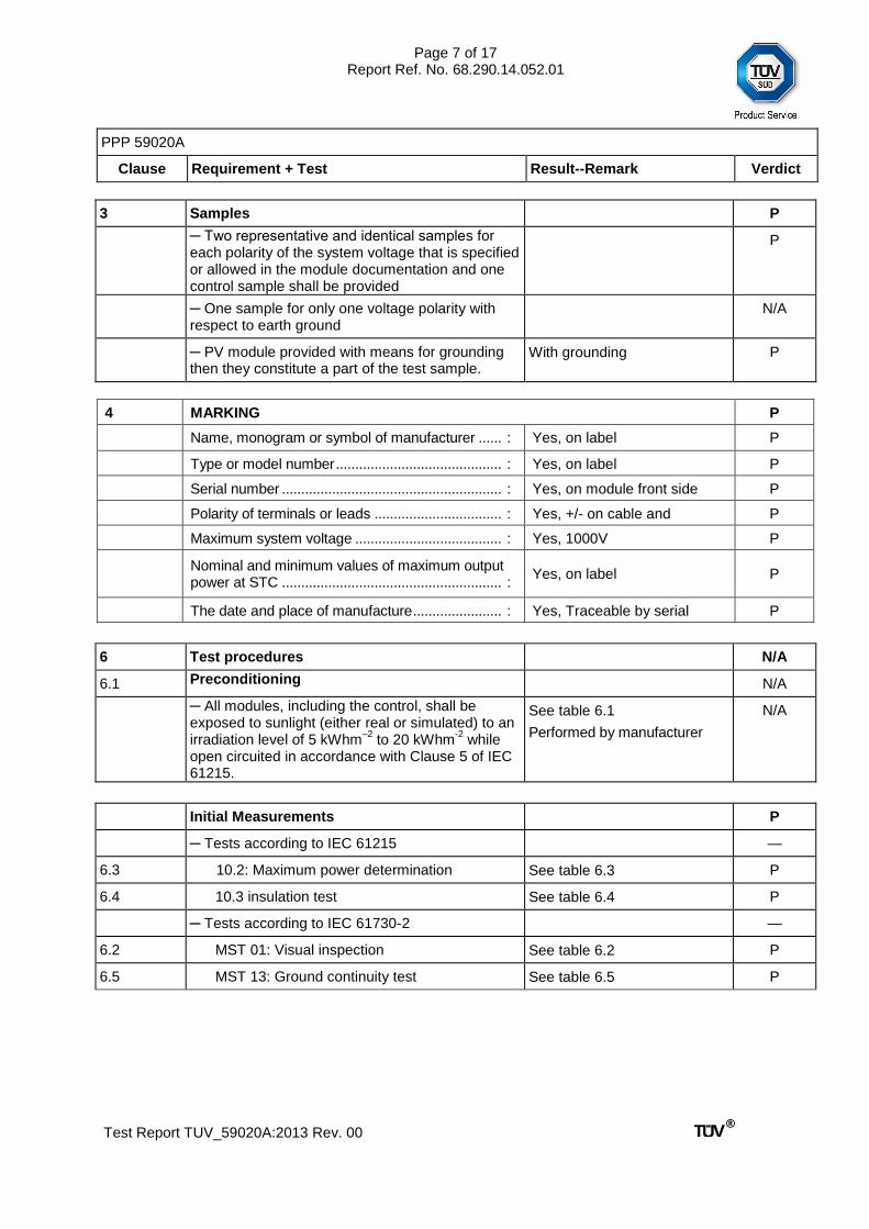
3 Samples P
Two representative and identical samples for each polarity of the system voltage that is specified or allowed in the module documentation and one control sample shall be provided
P
One sample for only one voltage polarity with respect to earth ground
N/A
PV module provided with means for grounding then they constitute a part of the test sample.
With grounding P
4 MARKING P
Name, monogram or symbol of manufacturer ...... : Yes, on label P
Type or model number ........................................... : Yes, on label P
Serial number ......................................................... : Yes, on module front side P
Polarity of terminals or leads ................................. : Yes, +/- on cable and connectors
P
Maximum system voltage ...................................... : Yes, 1000V P
Nominal and minimum values of maximum output power at STC ......................................................... :
Yes, on label P
The date and place of manufacture ....................... : Yes, Traceable by serial number
P
6 Test procedures N/A
6.1 Preconditioning N/A
All modules, including the control, shall be exposed to sunlight (either real or simulated) to an irradiation level of 5 kWhm
–2 to 20 kWhm
-2 while
open circuited in accordance with Clause 5 of IEC 61215.
See table 6.1
Performed by manufacturer
N/A
Initial Measurements P
Tests according to IEC 61215 —
6.3 10.2: Maximum power determination See table 6.3 P
6.4 10.3 insulation test See table 6.4 P
Tests according to IEC 61730-2 —
6.2 MST 01: Visual inspection See table 6.2 P
6.5 MST 13: Ground continuity test See table 6.5 P

Page 8 of 17 Report Ref. No. 68.290.14.052.01
PPP 59020A
Clause Requirement + Test Result--Remark Verdict
Test Report TUV_59020A:2013 Rev. 00
6.6 Damp heat test applied with voltage stress P
Test according to IEC 60068-2-78 See table 6.6 P
Final Measurements P
Tests according to IEC 61215 —
6.7 10.15: Wet leakage current test See table 6.7 P
6.8 10.2: Maximum power determination See table 6.8 P
6.10 10.3 insulation test See table 6.10 P
Tests according to IEC 61730-2 —
6.9 c) MST 01: Visual inspection See table 6.9 P
5 Requirements P
The degradation of maximum output power between initial and final power measurement does not exceed 5%
See table 6.8 P
There is no visual evidence of a major defect, as defined in Clause 7 of IEC 61215 and Clause 10.1.3 of IEC 61730-2
See table 6.9 P
The wet leakage current test requirements are met at the end of each sequence
See table 6.7 P
The insulation test requirements are met at the beginning and the end of each sequence
See table 6.4 and 6.10 P
Specific requirements of the individual test components are met
N/A

Page 9 of 17 Report Ref. No. 68.290.14.052.01
Test Report TUV_59020A:2013 Rev. 00
6.1 TABLE: Preconditioning —
Test Date [YYYY-MM-DD] start/end ............ : N/A —
Total irradiation dosage [kWh/m2 ] .............. : N/A —
Supplementary information: Preconditioning was performed by manufacturer
6.2 TABLE: Visual inspection (Initial) P
Test Date [YYYY-MM-DD]…………….....: 2014-08-29 —
Sample No. Nature and position of initial findings – comments or attach photos Verdict
1 No major defects found P
2 No major defects found P
3 No major defects found P
4 No major defects found P
5 No major defects found P
Supplementary information: N/A
6.3 TABLE: I-V characteristic (Initial) P
Test Date [YYYY-MM-DD]…………….....: 2014-08-29 —
Radiant Source…………………………….: Solar simulator Natural Sunlight
Module temperature [°C] ................................................. : Corrected to 25 —
Irradiance [W/m2] ............................................................. : Corrected to 1000 —
Sample No. Voc [V] Vmp [V] Isc [A] Imp [A] Pmp [W] FF[%]
1 37.8 30.5 8.63 8.19 249.5 76.5
2 37.8 30.3 8.66 8.23 249.3 76.1
3 37.8 30.3 8.65 8.25 249.8 76.4
4 38.0 30.3 8.61 8.23 249.2 76.6
5 38.0 30.3 8.64 8.25 250.0 76.5
Supplementary information: N/A
6.4 TABLE: Insulation test (initial) P
Test Date [YYYY-MM-DD] ....................... : 2014-08-29 —
Test Voltage applied [V] .......................... : 3000/1000 —
Sample # Measured Required Dielectric breakdown Result
MΩ MΩ Yes (description) No
1 5000 24.7 — No P
2 5000 24.7 — No P
3 5000 24.7 — No P
4 5000 24.7 — No P

Page 10 of 17 Report Ref. No. 68.290.14.052.01
Test Report TUV_59020A:2013 Rev. 00
5 24.7 — No P
Supplementary information: Size of module [m²]: 1.62
The maximum measurement range of the equipment is 5000 MΩ.
6.5 TABLE: MST 13 ground continuity test (Initial) P
Maximum over-current protection rating (A) ........... : 15
Current applied (A) ................................................. : 37.5
Location of designated grounding point .................. : Long frame side
Location of second contacting point ........................ : Opposite side
Sample No. Position in test sequence: Voltage (V) Resistance () Result
2 Initial examination 0.3000 0.008 P
3 Initial examination 0.1500 0.004 P
4 Initial examination 0.3000 0.008 P
5 Initial examination 0.2625 0.007 P
Supplementary information: N/A
6.6 TABLE: Damp heat test applied with voltage stress —
Test Date [YYYY-MM-DD] start/end ............ : 2014-08-30 / 2014-09-03 —
Chamber air temperature ( °C) ...................... : 85 ± 2 —
Chamber relative humidity ( % RH) ............... : 85 ± 5 —
Test duration hours (h) ................................. : 96 —
Sample # Applied voltage stress (V) and polarities —
2 1000 V d.c., positive system bias voltage —
3 1000 V d.c., positive system bias voltage —
4 1000 V d.c., negative system bias voltage —
5 1000 V d.c., negative system bias voltage —
Supplementary information:
The method of mounting grounding implemented according to the user manual installation method.
6.7 TABLE: Wet leakage current test (final) P
Test Date [YYYY-MM-DD]…………….....: 2014-09-03 —
Test voltage applied [V] ………………….: 1000 —
Module maximum system voltage rating (V, DC)................... : 1000 —
Solution resistivity [Ω cm], < 3,500 Ω cm at 22 ± 3 ............... : 2265 —
Sample No. Measured [MΩ] Limit [MΩ] Verdict
1 376.7 24.7 P
2 367.7 24.7 P
3 708.9 24.7 P
4 605.4 24.7 P
5 669.3 24.7 P

Page 11 of 17 Report Ref. No. 68.290.14.052.01
Test Report TUV_59020A:2013 Rev. 00
Supplementary information: Size of module [m²]: 1.62
Test according to CTL decision sheet no. DSH 0757, instead of IEC 61215:2005 Ed.2 Clause 10.15.2.a) use IEC 61646:2008 Ed.2 Clause 10.15.2.a).
6.8 TABLE: Maximum power determination (final) P
Test Date [YYYY-MM-DD] start-end ........ : 2014-09-03 —
Module temperature [°C] low-high ........... : Corrected to 25 —
Irradiance [W/m2] low-high ....................... : Corrected to 1000 —
Sample # Voc [V] Vmp [V] Isc [A] Imp [A] FF [%] Pmp [W] Degradation [%]
Limit [%]
1 37.8 30.4 8.59 8.15 76.3 247.6 -0.76 —
2 37.8 30.1 8.58 8.18 76.1 246.4 -1.16 5
3 37.8 30.2 8.59 8.17 76.0 246.5 -1.32 5
4 37.8 30.4 8.58 8.15 76.4 247.5 -0.68 5
5 37.8 30.3 8.57 8.15 76.4 247.2 -1.12 5
Supplementary information:
Crystalline silicon module: Pmp degradation after this test ≤ 5%
6.9 TABLE: Visual inspection (final) P
Test Date [YYYY-MM-DD]…………….....: 2014-09-03 —
Sample No. Nature and position of initial findings – comments or attach photos Verdict
1 No major defects found P
2 No major defects found P
3 No major defects found P
4 No major defects found P
5 No major defects found P
Supplementary information: N/A
6.10 Table: Insulation test (final) P
Test Date [YYYY-MM-DD] ....................... : 2014-09-03 —
Test Voltage applied [V] .......................... : 3000/1000 —
Sample # Measured Required Dielectric breakdown Result
MΩ MΩ Yes (description) No
1 5000 24.7 — No P
2 5000 24.7 — No P
3 5000 24.7 — No P
4 5000 24.7 — No P
5 5000 24.7 — No P
Supplementary information: Size of module [m²]: 1.62
The maximum measurement range of the equipment is 5000 MΩ.

Page 12 of 17 Report Ref. No. 68.290.14.052.01
Test Report TUV_59020A:2013 Rev. 00
Annex 1: List of measurement equipment
Description Identification # Application
Lamp SB08111 Visual inspection
Measuring tape SB08102 Visual inspection
Camera SB08092 Visual inspection
Ruler SB08108 Visual inspection
Illuminance meter SB08125 Visual inspection
Pulsed solar simulator SB08001 Maximum power determination
Electrical safety compliance analyzer SB10018 Insulation test/Wet leakage current test
Conductivity meter SB08054 Wet leakage current test
Wet leakage current tester SB08079 Wet leakage current test
Ground continuity tester SB08047 Ground continuity test
Chamber SB09008 Damp heat test applied with voltage stress
Annex 2: Statement of the estimated uncertainty of the test results
Power: 2.6% (K=2)

Page 13 of 17 Report Ref. No. 68.290.14.052.01
Test Report TUV_59020A:2013 Rev. 00
Annex 3: Photos of samples
Fig. 1 - Electroluminescence photos for sample #1 (Initial)
Fig. 2 - Electroluminescence photos for sample #1 (Final)

Page 14 of 17 Report Ref. No. 68.290.14.052.01
Test Report TUV_59020A:2013 Rev. 00
Fig. 3 - Electroluminescence photos for sample #2 (Initial)
Fig. 4 - Electroluminescence photos for sample #2 (Final)

Page 15 of 17 Report Ref. No. 68.290.14.052.01
Test Report TUV_59020A:2013 Rev. 00
Fig. 5 - Electroluminescence photos for sample #3 (Initial)
Fig. 6 - Electroluminescence photos for sample #3 (Final)

Page 16 of 17 Report Ref. No. 68.290.14.052.01
Test Report TUV_59020A:2013 Rev. 00
Fig. 7 - Electroluminescence photos for sample #4 (Initial)
Fig. 8 - Electroluminescence photos for sample #4 (Final)

Page 17 of 17 Report Ref. No. 68.290.14.052.01
Test Report TUV_59020A:2013 Rev. 00
Fig. 9 - Electroluminescence photos for sample #5 (Initial)
Fig. 10 - Electroluminescence photos for sample #5 (Final)
END OF REPORT