Report on Techniques for Bridge Strengthening
31
Report on Techniques for Bridge Strengthening Design Example – Stringer Retrofit - Composite Action and Continuity Changes June 2018 FHWA-HIF-18-044
Transcript of Report on Techniques for Bridge Strengthening

Report on Techniques for Bridge Strengthening
Design Example – Stringer Retrofit - Composite Action and Continuity
Changes
June 2018
FHWA-HIF-18-044

{cover back blank}
Foreword
This design example is targeted at bridge owners and bridge engineers who have been
tasked with strengthening an existing bridge. It is intended to be an aid in designing
appropriate bridge strengthening retrofits. Each example, in the set of examples, covers
a different situation for which strengthening is commonly needed.
This report is 1 of 5 reports, including a main report, funded under Task 6 of the FHWA
Cooperative Agreement DTFH61-11-H-0027.
Notice
This document is disseminated under the sponsorship of the U.S. Department of Transportation (USDOT) in the interest of information exchange. The U.S. Government assumes no liability for the use of the information contained in this document.
The U.S. Government does not endorse products or manufacturers. Trademarks or manufacturers’ names appear in this report only because they are considered essential to the objective of the document.
Quality Assurance Statement
The Federal Highway Administration (FHWA) provides high-quality information to serve Government, industry, and the public in a manner that promotes public understanding. Standards and policies are used to ensure and maximize the quality, objectivity, utility, and integrity of its information. FHWA periodically reviews quality issues and adjusts its programs and processes to ensure continuous quality improvement.

TECHNICAL REPORT DOCUMENTATION PAGE
1. Report No.FHWA-HIF-18-044
2. Government Accession No. 3. Recipient’s Catalog No.
4. Title and SubtitleReport on Techniques for Bridge Strengthening. Design Example – Stringer Retrofit - Composite Action and Continuity Changes.
5. Report DateSeptember 2018 6. Performing Organization Code:
7. Author(s)Ahlskog, C.
8. Performing Organization Report No.
9. Performing Organization Name and Address
Modjeski and Masters 100 Sterling Parkway, Suite 302 Mechanicsburg, PA 17050
10. Work Unit No.11. Contract or Grant No.
DTFH61-11-H-00027
12. Sponsoring Agency Name and Address
Federal Highway Administration Office of Infrastructure – Bridges and Structures 1200 New Jersey Ave., SE Washington, DC 20590
13. Type of Report and Period14. Sponsoring AgencyCode
15. Supplementary NotesWork funded by Cooperative Agreement “Advancing Steel and Concrete Bridge Technology to Improve Infrastructure Performance” between FHWA and Lehigh University. 16. AbstractThis example involves the replacement of stringers during re-decking on an existing truss/floorbeam/stringer bridge. The existing stringers are non-composite rolled W24x76 beams, that were designed for HS-20 live loads. The design criteria is to provide new stringers to obtain a HS-25 live load rating factor equal to or greater than 1.0, while minimizing the weight of the new stringers. The flexural live load ratings of the new stringers were significantly increased by both making the stringers composite with the new deck and changing the continuity of the stringer spans. This example only involves a study of the flexural resistance of a typical interior span for the new and existing stringers using the Strength-I Limit State. This example is based on AASHTO LRFD Bridge Design Specifications, 7th Edition.
17. Key Wordsstringer retrofit - composite action and continuity changes design example; design procedure; summary of design/analysis procedure; worked design example
18. Distribution StatementNo restrictions. This document is available to the public through the National Technical Information Service, Springfield, VA 22161. http://www.ntis.gov
19. Security Classif. (of this report)Unclassified
20. Security Classif. (of thispage) Unclassified
21. No. of Pages24
22. Price
Form DOT F 1700.7 (8-72) Reproduction of completed page authorized

STRINGER RETROFIT – COMPOSITE ACTION AND CONTINUITY CHANGES DESIGN EXAMPLE
Design Procedure The following American Association of State Highway and Transportation Officials (AASHTO) documents were used for this example.
Publication Title Publication Year
Publication Number
Available for Download
AASHTO LRFD Bridge Design Specifications, 7th Edition, 2014 2014 --- No
Guide Manual for Condition Evaluation and Load and Resistance Factor Rating (LRFR) of Highway Bridges, 2003
2003 __ Yes
Summary of Design/Analysis Procedure: First, the bridge data, material properties and section properties must be defined. It is also necessary to identify the standard or specification that will be used for the analysis/design along with the required design live loading and applicable load combinations and design factors.
The solution of the example will follow the following general steps:
Step 1. Calculate the new and existing dead load and live load moments.
Step 2. Calculate the non-composite and composite section properties for the new and existing stringers.
Step 3. Calculate nominal flexural resistance of the new and existing stringers.
Step 4. Calculate new and existing live load rating factors.
A summary will be given at the end of the example, comparing the changes between the new and existing stringer’s flexural resistances and the dead load and live load moments.
1

STRINGER RETROFIT – COMPOSITE ACTION AND CONTINUITY CHANGES DESIGN EXAMPLE
Symbols and Notation
Variables used throughout the design example are listed alphabetically below:
Ac3n = area of transformed slab for long term composite section (in.2) Acn = area of transformed slab for short term composite section (in.2) As = area of deck slab longitudinal reinforcing steel within effective width (in.2) Astr = gross area of rolled beam stringer(in.2) b3n = transformed width of deck slab for long term composite section (in.) beff = slab effective flange width for composite stringers (in.) bf = width of the flange of a rolled shape (in.) bn = transformed width of deck slab for short term composite section (in.) Cb = moment gradient modifier d = depth of a rolled shape (in.) dAs = distance between centers of gravity of the stringer and the slab steel (in.) DFM1 = moment live load distribution for single lane DFM2 = moment live load distribution for two lanes Dp = distance from top of deck to the N.A. of the composite section at the plastic moment (in.) d s = distance between centers of gravity of the stringer and the slab in compression (in.) Dt = total depth of composite section (in.) Ec = modulus of elasticity of concrete (ksi) eg = distance between centers of gravity of the beam and the deck (in.) Es = modulus of elasticity of steel (ksi) f’c = compressice strength of concrete deck slab (ksi) Fnc = nominal resistance of a flange (ksi) Fnc(FLB) = nominal compression flange local buckling flexural resistance (ksi) Fnc(LTB) = nominal compression flange lateral torsional buckling flexural resistance (ksi) Fue = specified minimum tensile strength of existing steel (ksi) Fun = specified minimum tensile strength of new steel (ksi) Fye = specified minimum yield strength of existing steel (ksi) Fyn = specified minimum yield strength of new steel (ksi) Fyr = compression flange stress at onset of nominal yielding (ksi) Ic3n = moment of inertia of long term composite section (in.4) Icn = moment of inertia of short term composite section (in.4) Icnf = moment of inertia of negative flexure composite section (in.4) IM = live load impact factor Ios3n = moment of inertia of transformed slab for long term composite section (in.4) Iosn = moment of inertia of transformed slab for short term composite section (in.4) Ix = moment of inertia of rolled beam about major principal axis (in.4) Kg = longitudinal stiffness parameter (in.4)
2
STRINGER RETROFIT – COMPOSITE ACTION AND CONTINUITY CHANGES DESIGN EXAMPLE
Symbols and Notation
Variables used throughout the design example are listed alphabetically below:
L = span length of stringer (ft) Lb = unbraced length of stringer (in.) Lp = limiting unbraced length to achieve nominal flexural resistance of Mp (in.) Lr = limiting unbraced length to achieve onset of nominal yielding in flange (in.) MAD = additional moment on short term composite section to cause nominal yielding (k-in.) MCR = elastic lateral torsional buckling moment(k-in.) MDC1 = moment due to non-composite dead load (k-in.) MDC2 = moment due to composite dead load (k-in.) MDW = moment due to wearing surface (k-in.) MLL = moment due to live load (k-in.) MLL+I = moment due to live load plus impact (k-in.) Mn = nominal moment resistance (k-in.) Mp = plastic moment (k-in.) Mr = factored flexural resistance (k-in.) Mu = moment due to factored loads (k-in.) MUL = moment from 1 kip/ft uniform load (k-in.) My = yield moment (k-in.) n = modular ratio, Es/Ec
ncs = number of stringer s in the cross section which share a DC2 or DW uniform dead load Rb = web load shedding factor RF = live load rating factor Rh = hybrid factor rT = radius of gyration of compression flange plus 1/3 of the compression web area (in.) S = stringer spacing in within cross section (in.) Sc3n bf = section modulus for bottom flange on long term composite section (in.3) Sc3n s = section modulus for slab on long term composite section (in.3) Scn bf = section modulus for bottom flange on short term composite section (in.3) Scn s = section modulus for slab flange on short term composite section (in.3) Sc nfbf = section modulus for bottom flange on negative flexure composite section (in.3) Sx = section modulus of existing member about the major principal axis (in.3) tf = thickness of the flange of a rolled shape (in.) thnch = thickness of haunch (in.) tsc = thickness of slab in compression for composite section (in.) tslab = thickness of deck slab (in.) tw = thickness of the web of a rolled shape (in.) uwc = uniform density weight of concrete (lb./ft3) uwDC1 = uniform weight of non-composite dead load (lb./ft) uwDC2 = uniform weight of composite dead load (lb./ft) uwDW = uniform density weight of wearing surface (lb./ft)
3
STRINGER RETROFIT – COMPOSITE ACTION AND CONTINUITY CHANGES DESIGN EXAMPLE
Symbols and Notation
Variables used throughout the design example are listed alphabetically below:
uwmb = uniform weight of median barrier (lb./ft) uwp = uniform weight of parapet (lb./ft) uws = uniform density weight of steel (lb./ft3) uwws = uniform density weight of wearing surface dead load (lb./ft3) Wc-c = the curb-to-curd width for wearing surface dead load (in.) wthnch = uniform weight of haunch per stringer (lb./ft) wtm = uniform weight of miscellaneous dead loads per stringer (lb./ft) wtmb = uniform weight of median barrier per stringer (lb./ft) wtp = uniform weight of parapet per stringer (lb./ft) wtslab = uniform weight of slab per stringer (lb./ft) wtstr = uniform weight of stringer (lb./ft) wtws = uniform weight of wearing surface per stringer (lb./ft) ybs = distance to bottom of slab in compression to c.g. of stringer (in.) ysc = distance between c.g of slab in compression to c.g. of stringer (in.) y’c3n = distance between c.g of stringer and c.g of long term composite section (in.) y’cn = distance between c.g of stringer and c.g of short term composite section (in.) y’cnf = distance between c.g of stringer and c.g of negative flexure composite section (in.) +Mc = factored flexural resistance for composite section in positive flexure (k-in.) +Mnc = factored flexural resistance for non-composite section in positive flexure (k-in.) -Mc = factored flexural resistance for composite section in negative flexure (k-in.) -Mnc = factored flexural resistance for non-composite section in negative flexure (k-in.) φMn = factored flexural resistance (k-in.) φc = resistance factor for compression φf = resistance factor for flexure φu = resistance factor for fracture on net section of tension member φy = resistance factor for yielding on gross section of tension member γDC = load factor for dead load, non-composite and composite γDW = load factor for future wearing surface γLL = load factor for live load and live load impact ηD = load modifier for ductility ηi = load modifier relating to ductility, redundancy and operational classification ηI = load modifier for operational classification ηR = load modifier for redundancy λf = slenderness ratio for the compression flange λpf = limiting slenderness ratio for a compact flange λrf = limiting slenderness ratio for a noncompact flange
4
STRINGER RETROFIT – COMPOSITE ACTION AND CONTINUITY CHANGES DESIGN EXAMPLE
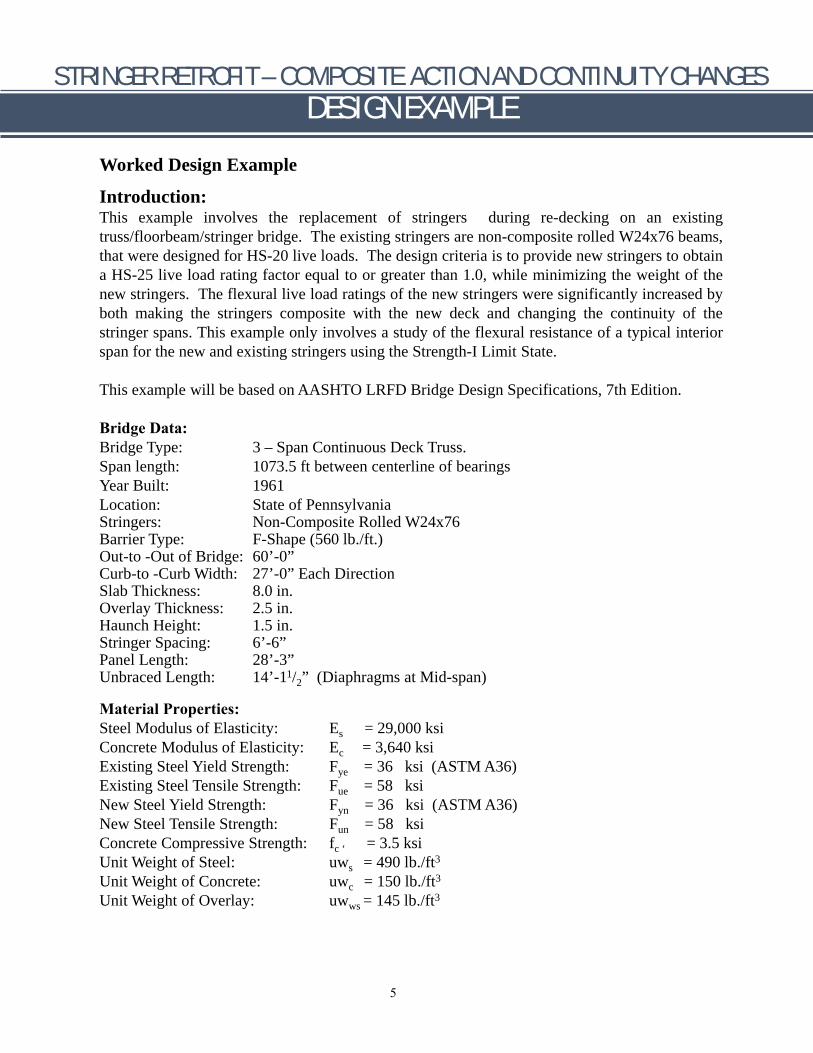
Worked Design Example
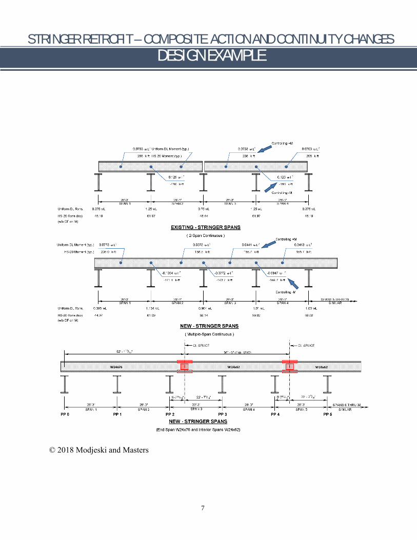
Introduction: This example involves the replacement of stringers during re-decking on an existing truss/floorbeam/stringer bridge. The existing stringers are non-composite rolled W24x76 beams, that were designed for HS-20 live loads. The design criteria is to provide new stringers to obtain a HS-25 live load rating factor equal to or greater than 1.0, while minimizing the weight of the new stringers. The flexural live load ratings of the new stringers were significantly increased by both making the stringers composite with the new deck and changing the continuity of the stringer spans. This example only involves a study of the flexural resistance of a typical interior span for the new and existing stringers using the Strength-I Limit State.
This example will be based on AASHTO LRFD Bridge Design Specifications, 7th Edition.
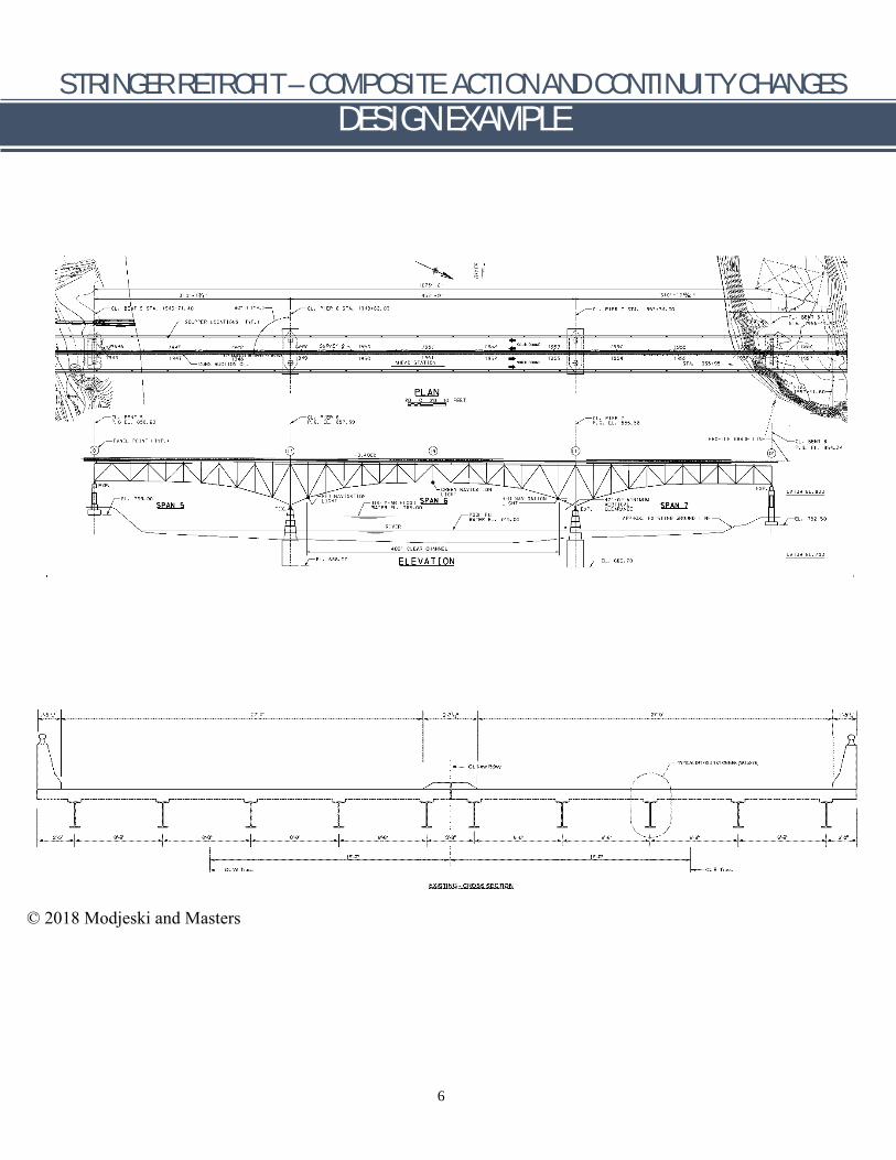
Bridge Data: Bridge Type: 3 – Span Continuous Deck Truss. Span length: 1073.5 ft between centerline of bearings Year Built: 1961 Location: State of Pennsylvania Stringers: Non-Composite Rolled W24x76 Barrier Type: F-Shape (560 lb./ft.)Out-to -Out of Bridge: 60’-0”Curb-to -Curb Width: 27’-0” Each Direction Slab Thickness: 8.0 in. Overlay Thickness: 2.5 in. Haunch Height: 1.5 in. Stringer Spacing: 6’-6” Panel Length: 28’-3” Unbraced Length: 14’-11/2” (Diaphragms at Mid-span)
Material Properties: Steel Modulus of Elasticity: Es = 29,000 ksi Concrete Modulus of Elasticity: Ec = 3,640 ksi Existing Steel Yield Strength: Fye = 36 ksi (ASTM A36) Existing Steel Tensile Strength: Fue = 58 ksi New Steel Yield Strength: Fyn = 36 ksi (ASTM A36) New Steel Tensile Strength: Fun = 58 ksi Concrete Compressive Strength: fc ‘ = 3.5 ksi Unit Weight of Steel: uws = 490 lb./ft3
Unit Weight of Concrete: uwc = 150 lb./ft3
Unit Weight of Overlay: uwws = 145 lb./ft3
5
STRINGER RETROFIT – COMPOSITE ACTION AND CONTINUITY CHANGES DESIGN EXAMPLE
6
© 2018 Modjeski and Masters
STRINGER RETROFIT – COMPOSITE ACTION AND CONTINUITY CHANGES DESIGN EXAMPLE
7
© 2018 Modjeski and Masters
STRINGER RETROFIT – COMPOSITE ACTION AND CONTINUITY CHANGES DESIGN EXAMPLE
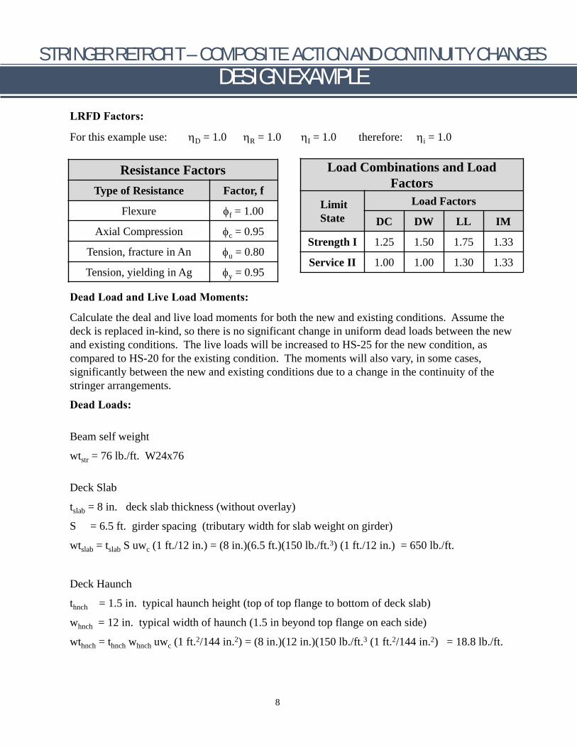
LRFD Factors:
For this example use: ηD = 1.0 ηR = 1.0 ηI = 1.0 therefore: ηi = 1.0
Resistance Factors Type of Resistance Factor, f
Flexure φf = 1.00
Axial Compression φc = 0.95
Tension, fracture in An φu = 0.80
Tension, yielding in Ag φy = 0.95
Load Combinations and Load Factors
Limit State
Load Factors
DC DW LL IM
Strength I 1.25 1.50 1.75 1.33
Service II 1.00 1.00 1.30 1.33
Dead Load and Live Load Moments:
Calculate the deal and live load moments for both the new and existing conditions. Assume the deck is replaced in-kind, so there is no significant change in uniform dead loads between the new and existing conditions. The live loads will be increased to HS-25 for the new condition, as compared to HS-20 for the existing condition. The moments will also vary, in some cases, significantly between the new and existing conditions due to a change in the continuity of the stringer arrangements.
Dead Loads:
Beam self weight
wtstr = 76 lb./ft. W24x76
Deck Slab
tslab = 8 in. deck slab thickness (without overlay)
S = 6.5 ft. girder spacing (tributary width for slab weight on girder)
wtslab = tslab S uwc (1 ft./12 in.) = (8 in.)(6.5 ft.)(150 lb./ft.3) (1 ft./12 in.) = 650 lb./ft.
Deck Haunch
thnch = 1.5 in. typical haunch height (top of top flange to bottom of deck slab)
whnch = 12 in. typical width of haunch (1.5 in beyond top flange on each side)
wthnch = thnch whnch uwc (1 ft.2/144 in.2) = (8 in.)(12 in.)(150 lb./ft.3 (1 ft.2/144 in.2) = 18.8 lb./ft.
8
STRINGER RETROFIT – COMPOSITE ACTION AND CONTINUITY CHANGES DESIGN EXAMPLE
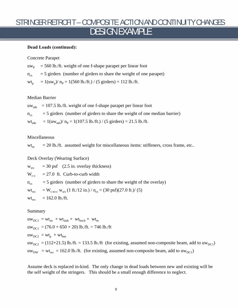
Dead Loads (continued):
Concrete Parapet
uwP = 560 lb./ft. weight of one f-shape parapet per linear foot
ncs = 5 girders (number of girders to share the weight of one parapet)
wtp = 1(uwp)/ nP = 1(560 lb./ft.) / (5 girders) = 112 lb./ft.
Median Barrier
uwmb = 107.5 lb./ft. weight of one f-shape parapet per linear foot
ncs = 5 girders (number of girders to share the weight of one median barrier)
wtmb = 1(uwmb)/ nP = 1(107.5 lb./ft.) / (5 girders) = 21.5 lb./ft.
Miscellaneous
wtm = 20 lb./ft. assumed weight for miscellaneous items: stiffeners, cross frame, etc..
Deck Overlay (Wearing Surface)
wws = 30 psf (2.5 in. overlay thickness)
Wc-c = 27.0 ft. Curb-to-curb width
ncs = 5 girders (number of girders to share the weight of the overlay)
wtws = Wc-to-c wws (1 ft./12 in.) / ncs = (30 psf)(27.0 ft.)/ (5)
wtws = 162.0 lb./ft.
Summary
= wtstr uwDC1 + wtslab + wthnch + wtm
uwDC1 = (76.0 + 650 + 20) lb./ft. = 746 lb./ft
uwDC2 = wtp + wtbm
uwDC2 = (112+21.5) lb./ft. = 133.5 lb./ft (for existing, assumed non-composite beam, add to uwDC1)
uwDW = wtws = 162.0 lb./ft. (for existing, assumed non-composite beam, add to uwDC1)
Assume deck is replaced in-kind. The only change in dead loads between new and existing will be the self weight of the stringers. This should be a small enough difference to neglect.
9
STRINGER RETROFIT – COMPOSITE ACTION AND CONTINUITY CHANGES DESIGN EXAMPLE
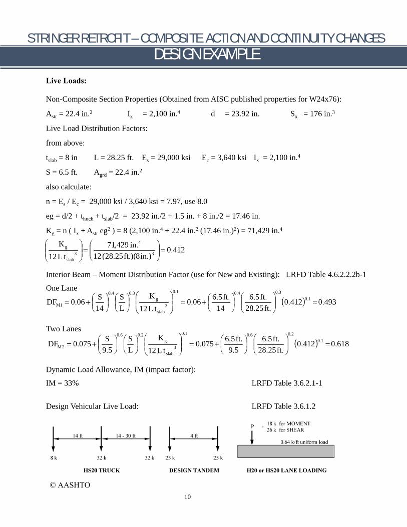
Live Loads:
Non-Composite Section Properties (Obtained from AISC published properties for W24x76):
Astr = 22.4 in.2 Ix = 2,100 in.4 d = 23.92 in. Sx = 176 in.3
Live Load Distribution Factors:
from above:
tslab = 8 in L = 28.25 ft. Es = 29,000 ksi Ec = 3,640 ksi Ix = 2,100 in.4
S = 6.5 ft. Agrd = 22.4 in.2
also calculate:
n = Es / Ec = 29,000 ksi / 3,640 ksi = 7.97, use 8.0
eg = d/2 + thnch + tslab/2 = 23.92 in./2 + 1.5 in. + 8 in./2 = 17.46 in.
Kg = n ( Ix + Astr eg2 ) = 8 (2,100 in.4 + 22.4 in.2 (17.46 in.)2) = 71,429 in.4
K 3 =
71,429 in.4
12(28.25ft.)(8in.)3
= 0.412
g
12L tslab
)(
Interior Beam – Moment Distribution Factor (use for New and Existing): LRFD Table 4.6.2.2.2b-1
One Lane S 0.10.412 L
0.1 0.30.4 0.3 0.4K
S 6.5ft. 6.5ft.
gDFM1 0.06 0.06 0.493
+ += = = 314 14 28.25ft.12 L tslab
Two Lanes 0.1 0.20.6 0.2 0.6K
S S 6.5ft. 6.5ft.
)(0.412 0.1
Dynamic Load Allowance, IM (impact factor):
IM = 33% LRFD Table 3.6.2.1-1
Design Vehicular Live Load: LRFD Table 3.6.1.2
gDFM2 0.075 0.075 =0.618++ == 39.5 L 9.5 28.25ft.12L tslab
10
© AASHTO
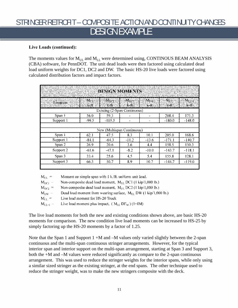
DESIGN MOMENTS
MLL+IMUL MDCI MDC2 MDw MLLLocation k-ft k-ft k-ft k-ft k-ft k-ft
Existing (2-Span Continuous) Span 1 56.0 59.3 - - 208.4 171.3
Support 1 -99.5 -105.5 - - -180.0 -148.0
New (Multispan Continuous) Span 1 62.1 47.5 8.3 10.1 205.0 168.6
Support 1 -84.1 -64.3 -11.2 -13.6 -171.1 -140.7Span 2 26.9 20.6 3.6 4.4 158.5 130.3
Support 2 -61.6 -47.1 -8.2 -10.0 -143.7 -118.1
Span 3 33.4 25.6 4.5 5.4 155.8 128.1
Support 3 66.3 50.7 8.9 10.7 -144.7 -119.0
Moment on simple span with 1 k./ft. uniform unit load. Non-composite dead load moment, MUL DC1 (1 kip/1,000 lb.)Non-composite dead load moment, MULDC2(1 kip/1,000 lb.)Dead load moment from wearing surface, MUL DW (1 kip/1,000 lb.) Live load moment for HS-20 Truck Live load moment plus impact, ( MLL DFM) (1+IM)
MUL = MDC1 = MDC2 = MDW =MLL =
MLL+I =
STRINGER RETROFIT – COMPOSITE ACTION AND CONTINUITY CHANGES DESIGN EXAMPLE
Live Loads (continued):
The moments values for MUL and MLL were determined using, CONTINOUS BEAM ANALYSIS (CBA) software, for PennDOT. The unit dead loads were then factored using calculated dead load uniform weights for DC1, DC2 and DW. The basic HS-20 live loads were factored using calculated distribution factors and impact factors.
The live load moments for both the new and existing conditions shown above, are basic HS-20 moments for comparison. The new condition live load moments can be increased to HS-25 by simply factoring up the HS-20 moments by a factor of 1.25.
Note that the Span 1 and Support 1 +M and –M values only varied slightly between the 2-span continuous and the multi-span continuous stringer arrangements. However, for the typical interior span and interior support on the multi-span arrangement, starting at Span 3 and Support 3, both the +M and –M values were reduced significantly as compare to the 2-span continuous arrangement. This was used to reduce the stringer weights for the interior spans, while only using a similar sized stringer as the existing stringer, at the end spans. The other technique used to reduce the stringer weight, was to make the new stringers composite with the deck.
11

STRINGER RETROFIT – COMPOSITE ACTION AND CONTINUITY CHANGES DESIGN EXAMPLE
Determine the Non-composite and Composite Section Properties:
12 © 2018 Modjeski and Masters
STRINGER RETROFIT – COMPOSITE ACTION AND CONTINUITY CHANGES DESIGN EXAMPLE
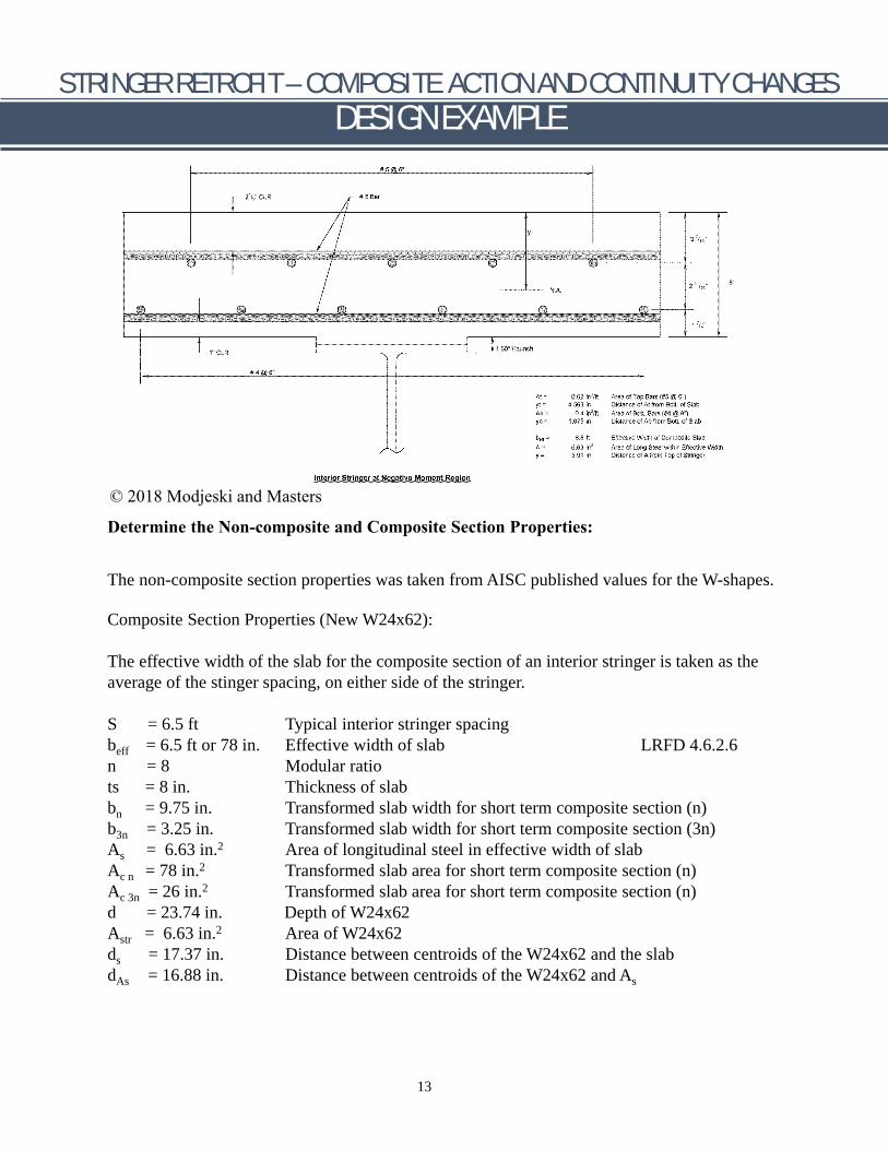
Determine the Non-composite and Composite Section Properties:
The non-composite section properties was taken from AISC published values for the W-shapes.
Composite Section Properties (New W24x62):
The effective width of the slab for the composite section of an interior stringer is taken as the average of the stinger spacing, on either side of the stringer.
S = 6.5 ft Typical interior stringer spacing beff = 6.5 ft or 78 in. Effective width of slab LRFD 4.6.2.6 n = 8 Modular ratio ts = 8 in. Thickness of slab bn = 9.75 in. Transformed slab width for short term composite section (n) b3n = 3.25 in. Transformed slab width for short term composite section (3n) As = 6.63 in.2 Area of longitudinal steel in effective width of slab Ac n = 78 in.2 Transformed slab area for short term composite section (n) Ac 3n = 26 in.2 Transformed slab area for short term composite section (n) d = 23.74 in. Depth of W24x62 Astr = 6.63 in.2 Area of W24x62 ds = 17.37 in. Distance between centroids of the W24x62 and the slab dAs = 16.88 in. Distance between centroids of the W24x62 and As
13
© 2018 Modjeski and Masters
STRINGER RETROFIT – COMPOSITE ACTION AND CONTINUITY CHANGES DESIGN EXAMPLE
Determine the Non-composite and Composite Section Properties (continued):
Short Term (n)Composite Section Properties (New W24x62):
y’cn = (Astr ystr+Acn ds) / (Astr+Acn) = ((18.2 in.2)(0 in.)+(78 in.2)(17.37 in.)) / (18.2 in.2+78 in.2) y’cn = 14.08 in. distance from centroids of the W24x62 and the composite section.
y’cn = 14.08 in. > d/2 = 23.74/2 = 11.87 in., which put the c.g. of the composite section into the slab. The slab concrete below the c.g. must not be used, since this is the tension zone. Therefore adjust the Acn and ds values and recalculate y’cn, this may take several iterations.
Assume only the top 7.26 in. of the slab are in compression.
Acn = 7.26 in. (9.75 in.) = 70.77 in.2
ds = d/2 + thnch + ts – tsc/2= 11.87 in. + 1.5 in. +8 in. – (7.26 in.)/2 = 17.74 in.
y’cn = ((18.2 in.2)(0 in.)+(70.77 in.2)(17.74 in.)) / (18.2 in.2+70.77 in.2) = 14.11 in.
Check the location of the bottom of the assumed slab in compression.
ybs = d/2 + thnch + ts – tsc= 11.87 in. + 1.5 in. +8 in. – 7.26 in. = 14.11 in = y’cn OK
Determine the short term composite section moment of inertia, Ic n, section modulus for the top of slab, Scn s and the bottom of the bottom flange, Scn bf.
ds = tsc/2 = 7.26 in. / 2 = 3.63 in. Iosn = (tsc
3 bn) / 12 = (( 7.26 in.)3(9.75 in))/ 12 = 310.91 in.4
Icn = Σ Io + Σ Ad2 = Iosn + Acn ds2 + Istr + Astr y’cn
2
Icn = 310.91 in.4 + (70.77 in.2)(3.63 in.)2 + 1,550 in.4 + (18.2 in.2)(14.11 in.)2 = 6,418 in.4
Scn s = Icn / tsc = 6,418 in.4 / 7.26 in. = 884 in.3
Scn bf = Icn / (y’cn + d/2)= 6,418 in.4 / (14.11 in. + 11.87 in.) = 247 in.3
14

STRINGER RETROFIT – COMPOSITE ACTION AND CONTINUITY CHANGES DESIGN EXAMPLE
Determine the Non-composite and Composite Section Properties (continued):
Long Term (3n)Composite Section Properties (New W24x62):
y’c3n = (Astr ystr+Ac3n ds) / (Astr+Ac3n) = ((18.2 in.2)(0 in.)+(26 in.2)(17.37 in.)) / (18.2 in.2+26 in.2) y’c3n = 10.22 in. distance from centroid of the W24x62 to the composite section
y’c3n = 10.22 in. < d/2 = 23.74/2 = 11.87 in., which puts the c.g. of the composite section into the rolled steel shape. Therefore the assumption of using the full slab thickness is OK.
Determine the long term composite section moment of inertia, Ic 3n, section modulus for the top of slab, Sc3n s and the bottom of the bottom flange, Sc3n bf.
Ios3n = (ts3 b3n) / 12 = (( 8 in.)3(3.25 in))/ 12 = 138.67 in.4
ds = d/2 + thnch + ts /2 – y’c3n = 11.87 in. + 1.5 in. + 4 in. – 10.22 in. = 7.15 in.
Ic3n = Σ Io + Σ Ad2 = Ios3n + Acn ds2 + Istr + Astr y’c3n
2
Ic3n = 138.67 in.4 + (26 in.2)(7.15 in.)2 + 1,550 in.4 + (18.2 in.2)(10.22 in.)2 = 4,920 in.4
Sc3n s = Ic3n / (ds + ts / 2 )= 4,920 in.4 / (7.15 in.+ (8 in.)/2 ) = 441 in.3
Sc3n bf = Ic3n / (y’c3n + d/2)= 4,920 in.4 / (10.22 in. + 11.87 in.) = 223 in.3
Negative Flexure Composite Section Properties (New W24x62):
y’cnf = (Astr ystr+As dAs) / (Astr+As) = ((18.2 in.2)(0 in.)+(6.63 in.2)(16.88 in.)) /(18.2 in.2+6.63 in.2) y’cnf = 4.51 in.
Determine the negative flexure composite section moment of inertia, Ic nf, and the section modulus for the bottom of the bottom flange, Scnf bf.
Icnf = Σ Io + Σ Ad2 = As (dAs - y’cnf )2 + Istr + Astr y’cnf 2
Icnf = (6.63 in.2)(16.88 - 4.51 in.)2 + 1,550 in.4 + (18.2 in.2)(4.51 in.)2 = 2,935 in.4
Sc nfbf = Icnf / (ds / 2 + y’cnf)= 2,935 in.4 / (11.87 in.+ 4.51)= 179 in.3
15
STRINGER RETROFIT – COMPOSITE ACTION AND CONTINUITY CHANGES DESIGN EXAMPLE
Determine Existing and New Factored Flexural Resistances: The top flange of the existing stringers are fully embedded into the concrete deck slab. Per AASHTO Manual for Condition Evaluation of Bridges, Section 6.6.9.3 and C6.6.9.3, the top flange may be assumed to be adequately braced by the concrete deck. The flexural resistance calculations for positive flexure will be based on a continually braced compression flange. For negative flexure, the bottom flange is braced by diaphragms at the floorbeams and midspan, so the unbraced length is 28.25 ft. / 2 = 14.125 ft.
Existing W24x76 Non-composite Flexural Resistance:
Compression Flange Flexural Resistance – Flange Local Buckling: b 8.99in.
λ = ft = = 6.61f LRFD Eqn. 6.10.8.2.2-3 2 tft 2(0.68in.) E 29,000 ksi
λ = 0.38 = 0.38 = 10.785 LRFD Eqn. 6.10.8.2.2-4 pf Fy 36ksi
E 29,000 ksi LRFD Eqn. 6.10.8.2.2-5 λ rf = 0.56 = 0.56 = 15.894Fy 36 ksi
if λf ≤ λpf , 6.61 ≤ 10.784 yes, then Fnc(FLB) = Fy =36 ksi LRFD Eqn. 6.10.8.2.2-1
Compression Flange Flexural Resistance – Lateral Torsional Buckling: r = 2.29in. F = 0.7F = 25.2 ksi R = 1.0 R = 1.0 and C = 1.0T yr y h b b
29,000 ksi Lp = 1.0 r E = 2.29in. = 65.0in. LRFD Eqn. 6.10.8.2.3-1 T Fy 36ksi
E 29,000 ksi = 245in. LRFD Eqn. 6.10.8.2.3-5 Lr = π rT = π (2.29in.)
25.2 ksi Fyr
if Lb ≤ Lp , 169.5in. ≤ 65in., then Fnc(LTB) = Fy =36 ksi LRFD Eqn. 6.10.8.2.3-1 and 2
else if Lp < Lb ≤ Lr , 65 in. < 169.5in. ≤ 245 in., then
F L − L yr b pFnc(LTB) = Cb 1− 1−
R bR hFy =R F L − L h y r p
25.2 ksi 169.5 in.− 65 in. Fnc(LTB) =1.01− 1− 36 ksi = 29.73 ksi
36 ksi 245 in.− 65 in.
16

STRINGER RETROFIT – COMPOSITE ACTION AND CONTINUITY CHANGES DESIGN EXAMPLE
New W24x62 Non-composite Flexural Resistance:
Compression Flange Flexural Resistance – Flange Local Buckling: bft 7.04in.
λf = = = 5.972 tft 2(0.59in.) LRFD Eqn. 6.10.8.2.2-3
E 29,000 ksi λ = 0.38 = 0.38 = 10.785 LRFD Eqn. 6.10.8.2.2-4 pf Fy 36ksi
E 29,000 ksi = 15.894 LRFD Eqn. 6.10.8.2.2-5 λ rf = 0.56 = 0.56
Fy 36 ksi if λf ≤ λpf , 5.97 ≤ 10.784 yes, then Fnc(FLB) = Fy =36 ksi LRFD Eqn. 6.10.8.2.2-1
Compression Flange Flexural Resistance – Lateral Torsional Buckling:
r = 1.71in. F = 0.7F = 25.2 ksi R = 1.0 R = 1.0 and C = 1.0T yr y h b b
E 29,000ksi L = 1.0 r = 1.71in. = 48.5in.p T LRFD Eqn. 6.10.8.2.3-1 Fy 36 ksi
E 29,000 ksi = 182in. LRFD Eqn. 6.10.8.2.3-5 Lr = π rT = π (1.71in.)
25.2 ksi Fyr
if Lb ≤ Lp , 169.5in. ≤ 48.5in., then Fnc(LTB) = Fy =36ksi LRFD Eqn. 6.10.8.2.3-1 and 2 else if Lp < Lb ≤ Lr , 48.5 in. < 169.5in. ≤ 182 in., then
F L − L yr b pFnc(LTB) = Cb 1−
1−
R bR hFy =R F L − L h y r p
25.2 ksi 169.5 in.− 48.5 in.Fnc(LTB) =1.01− 1− 36 ksi = 26.2 ksi
36 ksi 182 in.− 48.5 in.
17
STRINGER RETROFIT – COMPOSITE ACTION AND CONTINUITY CHANGES DESIGN EXAMPLE
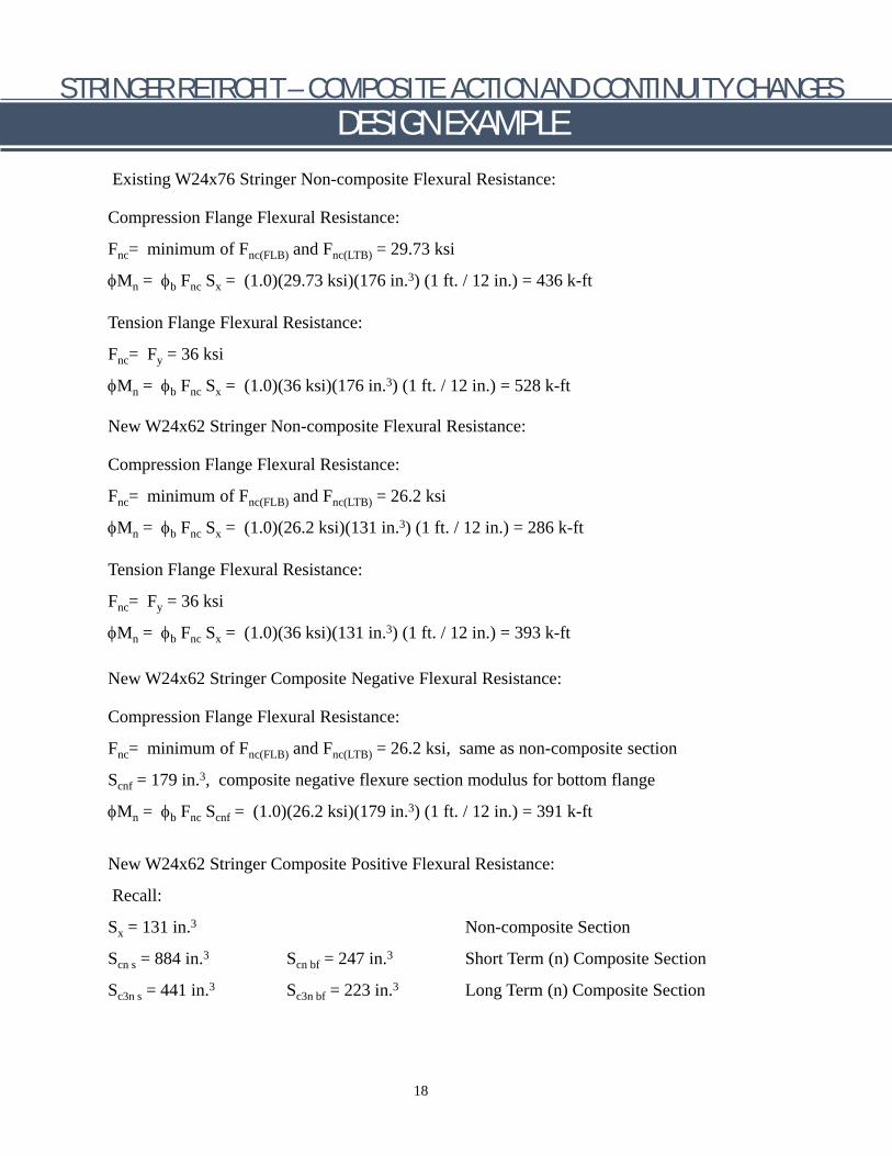
Existing W24x76 Stringer Non-composite Flexural Resistance:
Compression Flange Flexural Resistance:
Fnc= minimum of Fnc(FLB) and Fnc(LTB) = 29.73 ksi
φMn = φb Fnc Sx = (1.0)(29.73 ksi)(176 in.3) (1 ft. / 12 in.) = 436 k-ft
Tension Flange Flexural Resistance:
Fnc= Fy = 36 ksi
φMn = φb Fnc Sx = (1.0)(36 ksi)(176 in.3) (1 ft. / 12 in.) = 528 k-ft
New W24x62 Stringer Non-composite Flexural Resistance:
Compression Flange Flexural Resistance:
Fnc= minimum of Fnc(FLB) and Fnc(LTB) = 26.2 ksi
φMn = φb Fnc Sx = (1.0)(26.2 ksi)(131 in.3) (1 ft. / 12 in.) = 286 k-ft
Tension Flange Flexural Resistance:
Fnc= Fy = 36 ksi
φMn = φb Fnc Sx = (1.0)(36 ksi)(131 in.3) (1 ft. / 12 in.) = 393 k-ft
New W24x62 Stringer Composite Negative Flexural Resistance:
Compression Flange Flexural Resistance:
Fnc= minimum of Fnc(FLB) and Fnc(LTB) = 26.2 ksi, same as non-composite section
Scnf = 179 in.3, composite negative flexure section modulus for bottom flange
φMn = φb Fnc Scnf = (1.0)(26.2 ksi)(179 in.3) (1 ft. / 12 in.) = 391 k-ft
New W24x62 Stringer Composite Positive Flexural Resistance:
Recall:
Sx = 131 in.3 Non-composite Section
Scn s = 884 in.3 Scn bf = 247 in.3 Short Term (n) Composite Section
Sc3n s = 441 in.3 Sc3n bf = 223 in.3 Long Term (n) Composite Section
18
STRINGER RETROFIT – COMPOSITE ACTION AND CONTINUITY CHANGES DESIGN EXAMPLE
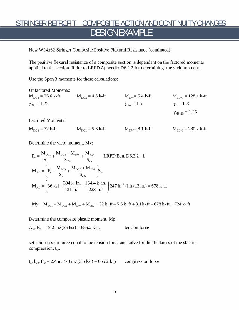
New W24x62 Stringer Composite Positive Flexural Resistance (continued):
The positive flexural resistance of a composite section is dependent on the factored moments applied to the section. Refer to LRFD Appendix D6.2.2 for determining the yield moment .
Use the Span 3 moments for these calculations:
Unfactored Moments: MDC1 = 25.6 k-ft MDC2 = 4.5 k-ft MDW= 5.4 k-ft MLL+I = 128.1 k-ft γDC = 1.25 γDw = 1.5 γL = 1.75
γHS-25 = 1.25
Factored Moments:
MDC1 = 32 k-ft MDC2 = 5.6 k-ft MDW= 8.1 k-ft MLL+I = 280.2 k-ft
Determine the yield moment, My:
MDC1 M + MDW MDC2 ADFy = + + LRFD Eqn. D6.2.2 −1Sx Sc3n Scn
M M + M DC1 DC2 DWM = F − + SAD y S S cn x c3n
304 k ⋅ in. 164.4 k ⋅ in. 3M = 36 ksi − + ⋅247 in. (1 ft /12 in.) = 678 k ⋅ ftAD 3 3131in. 223 in.
My = M + M + M + M = 32 k ⋅ ft + 5.6 k ⋅ ft + 8.1 k ⋅ ft + 678 k ⋅ ft = 724 k ⋅ ftDC1 DC2 DW AD
Determine the composite plastic moment, Mp:
Astr Fy = 18.2 in.2(36 ksi) = 655.2 kip, tension force
set compression force equal to the tension force and solve for the thickness of the slab in compression, tsc.
tsc beff f’c = 2.4 in. (78 in.)(3.5 ksi) = 655.2 kip compression force
19

FACTORED FLEXURAL RESISTANCES Positive Flexure Negative Flexure
Stringer +Mnc +MC -Mnc -Mc k-ft k-ft k-ft k-ft
Existing W24×76 528 - 436 -
New W24×62 393 941 286 391
Difference (k-ft) 548 k-ft 413 k-ft 105 k-ft -45 k-ft Difference (%) + 139% + 78 % 37% -10%
+Mnc = Non-composite factored, positive flexural resistance +MC = Composite factored, positive flexural resistance (based on Span 3, factored moments at STR-I) -MNC = Non-composite factored, negative flexural resistance -Mc = Composite factored, negative flexural resistance
Note: Positive moment is flexure causing tension in the bottom flange.
STRINGER RETROFIT – COMPOSITE ACTION AND CONTINUITY CHANGES DESIGN EXAMPLE
New W24x62 Stringer Composite Positive Flexural Resistance (continued): ds = tsc /2 = 2.4 in. / 2 = 1.2 in. dstr = d/2 + thnch + ts – tsc = 11.87 in. + 1.5 in. + 8 in. – 2.4 in =18.97 in.
Mp = beff tsc f’c ds + Astr Fy dstr = 78 in.(2.4 in.)(3.5 ksi)(1.2 in.) +18.2 in.2 (36 ksi)(18.97 in.) Mp = 13,215 k-In. or 1,101 k-ft
Using LRFD 6.10.7.1.2 – Nominal Flexural Resistance (Composite Section in Positive Flexure) Dp = tsc = 2.4 in Dt = d + thnch + ts = 23.74 in. + 1.5 in. + 8 in. =33.24 in.
if Dp = 2.4 in. ≤ 0.1 Dt = 3.32 in., yes then Mn = Mp = 1,101 k ⋅ ft and Mn ≤ 1.3 My = 1.3 (724 k ⋅ ft) = 941 k ⋅ ft
φf Mn = 1.0(941 k ⋅ ft) = 941 k ⋅ ft
Summarize the Factored Flexural Resistance for the new and existing stringers.
20
STRINGER RETROFIT – COMPOSITE ACTION AND CONTINUITY CHANGES DESIGN EXAMPLE
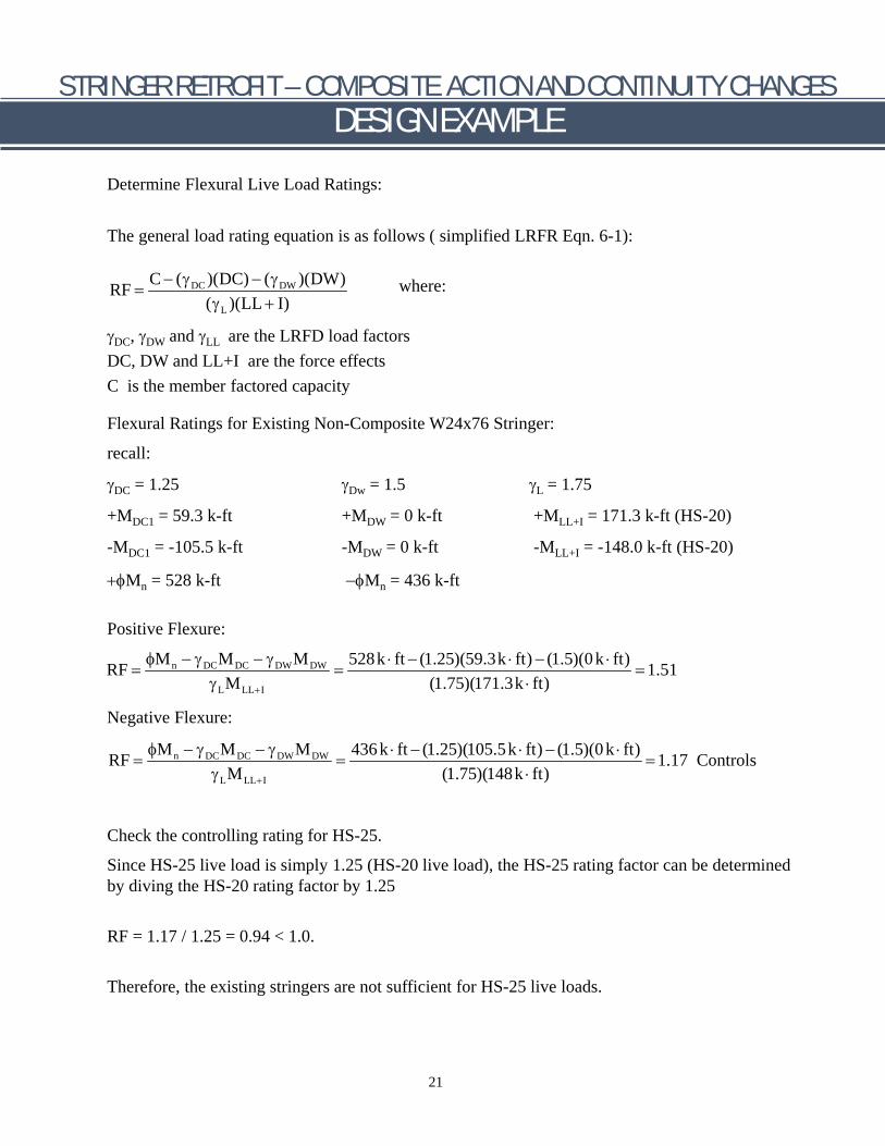
Determine Flexural Live Load Ratings:
The general load rating equation is as follows ( simplified LRFR Eqn. 6-1):
C − (γ )(DC) − (γ )(DW)DC DW where:RF = (γL )(LL + I)
γDC, γDW and γLL are the LRFD load factors DC, DW and LL+I are the force effects C is the member factored capacity
Flexural Ratings for Existing Non-Composite W24x76 Stringer:
recall:
γDC = 1.25 γDw = 1.5 γL = 1.75
+MDC1 = 59.3 k-ft +MDW = 0 k-ft +MLL+I = 171.3 k-ft (HS-20)
-MDC1 = -105.5 k-ft -MDW = 0 k-ft -MLL+I = -148.0 k-ft (HS-20)
+φMn = 528 k-ft −φMn = 436 k-ft
Positive Flexure:
φMn − γDCMDC − γDWMDW 528k ⋅ ft − (1.25)(59.3k ⋅ ft) − (1.5)(0 k ⋅ ft)RF = = = 1.51γ M (1.75)(171.3k ⋅ ft)L LL+I
Negative Flexure:
φMn − γDCMDC − γDWMDW 436k ⋅ ft − (1.25)(105.5k ⋅ ft) − (1.5)(0 k ⋅ ft)RF = = = 1.17 ControlsγLMLL+I (1.75)(148k ⋅ ft)
Check the controlling rating for HS-25.
Since HS-25 live load is simply 1.25 (HS-20 live load), the HS-25 rating factor can be determined by diving the HS-20 rating factor by 1.25
RF = 1.17 / 1.25 = 0.94 < 1.0.
Therefore, the existing stringers are not sufficient for HS-25 live loads.
21
STRINGER RETROFIT – COMPOSITE ACTION AND CONTINUITY CHANGES DESIGN EXAMPLE
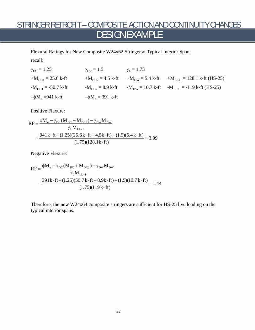
Flexural Ratings for New Composite W24x62 Stringer at Typical Interior Span:
recall:
γDC = 1.25 γDw = 1.5 γL = 1.75
+MDC1 = 25.6 k-ft +MDC2 = 4.5 k-ft +MDW = 5.4 k-ft +MLL+I = 128.1 k-ft (HS-25)
-MDC1 = -50.7 k-ft -MDC2 = 8.9 k-ft -MDW = 10.7 k-ft -MLL+I = -119 k-ft (HS-25)
+φMn =941 k-ft −φMn = 391 k-ft
Positive Flexure:
φM − γ (M + M ) − γ Mn DC DC DC2 DW DWRF = γ ML LL+I
941k ⋅ ft − (1.25)(25.6k ⋅ ft + 4.5k ⋅ ft) − (1.5)(5.4 k ⋅ ft)= = 3.99
(1.75)(128.1k ⋅ ft)
Negative Flexure:
φM − γ (M + M ) − γ Mn DC DC DC2 DW DWRF = γ ML LL+I
391k ⋅ ft − (1.25)(50.7 k ⋅ ft + 8.9k ⋅ ft) − (1.5)(10.7 k ⋅ ft)= = 1.44
(1.75)(119k ⋅ ft)
Therefore, the new W24x64 composite stringers are sufficient for HS-25 live loading on the typical interior spans.
22
STRINGER RETROFIT – COMPOSITE ACTION AND CONTINUITY CHANGES DESIGN EXAMPLE
Summary
Using the methods of making the new stringers composite with the deck and changing the continuity of the new stringers, it was possible to use a lighter stringer sections, even with a 25% increase in the live loading (HS-20 to HS-25).
The following is a brief discussion for each of the methods used:
Non-composite to Composite stringers:
For positive flexure, there is a significant increase in the flexural resistance for a composite section compared with a non-composite section. For this example, there was a 139% increase in the flexural resistance for a composite W24x62 in positive flexure compared to a non-composite W24x62 in positive flexure.
For negative flexure, there is a less significant increase in the flexural resistance for a composite section compared with a non-composite section. For a composite section in negative flexure, the longitudinal deck reinforcing steel within the effective width can be considered in the flexural resistance. For this example, there was a 37% increase in the flexural resistance for a composite W24x62 in negative flexure compared to a non-composite W24x62 in negative flexure.
Change in Stringer Continuity from 2-Span Continuous to Multi-span Continuous:
For this example, there was a significant reduction in both the positive and negative moments in the multi-span arrangement compared to the 2-span arrangement. The moment reductions begin in Span 2 and Support 3 and continue for the typical interior spans. Span 3 and Support 4 has slightly higher moments than the typical interior span, so these were the moments used in the live load ratings. There were only small differences in the Span 1 and Support 2 moments between the 2-span and multi-span arrangements. This resulted in no reduction in the stringer size for the end 2 spans. The positive flexure composite resistance was increased significantly but the negative composite flexural resistance was not increased enough to compensated for the increased HS-25 live loading in the new condition.
23
STRINGER RETROFIT – COMPOSITE ACTION AND CONTINUITY CHANGES DESIGN EXAMPLE
References Page
AISC, 1989, Manual of Steel Construction – Allowable Stress Design, 9th Edition, AISC, Chicago, IL.
AASHTO (2014). AASHTO LRFD Bridge Design Specifications, Customary U.S. Units, 7th Ed., AASHTO, Washington, D.C.
AASHTO (2003). Guide Manual for Condition Evaluation and Load and Resistance Factor Rating (LRFR) of Highway Bridges, First Edition, with 2005 Interim Revisions, AASHTO, Washington, D.C.
24

{inside back cover blank}

FHWA-HIF-18-044