Report of Geotechnical Study - Port...
51
Corporate HQ: 3015 Dumbarton Road Richmond, Virginia 23228 T 804.264.2701 F 804.264.1202 www.fandr.com VIRGINIA • NORTH CAROLINA • SOUTH CAROLINA • MARYLAND • DISTRICT OF COLUMBIA A Minority-Owned Business Report of Geotechnical Study Baltimore Sun Consolidation Baltimore, Maryland F&R Project No. 75V0084 Prepared For: Bohler Engineering 901 Dulaney Valley Road, Suite 801 Towson, MD 21204 Prepared By: Froehling & Robertson, Inc. 10626 York Road, Suites C-D Cockeysville, Maryland 21030 October 20, 2017
Transcript of Report of Geotechnical Study - Port...

Corporate HQ: 3015 Dumbarton Road Richmond, Virginia 23228 T 804.264.2701 F 804.264.1202 www.fandr.com
VIRGINIA • NORTH CAROLINA • SOUTH CAROLINA • MARYLAND • DISTRICT OF COLUMBIA
A Minority-Owned Business
Report of Geotechnical Study
Baltimore Sun Consolidation Baltimore, Maryland
F&R Project No. 75V0084
Prepared For:
Bohler Engineering 901 Dulaney Valley Road, Suite 801
Towson, MD 21204
Prepared By: Froehling & Robertson, Inc. 10626 York Road, Suites C-D
Cockeysville, Maryland 21030
October 20, 2017


Bohler Engineering Baltimore Sun Consolidation – Baltimore, MD
F&R Project No. 75V0084 October 20, 2017
Page - ii -
TABLE OF CONTENTS
SECTION PAGE
EXECUTIVE SUMMARY .......................................................................................................................1
1.0 PURPOSE & SCOPE OF SERVICES ..............................................................................................2
2.0 PROJECT INFORMATION ..........................................................................................................3
2.1 SITE DESCRIPTION....................................................................................................................3 2.2 PROPOSED CONSTRUCTION ........................................................................................................3
3.0 EXPLORATION PROCEDURES ...................................................................................................4
3.1 SUBSURFACE EXPLORATION .......................................................................................................4 3.2 INFILTRATION TESTING ..............................................................................................................5 3.3 LABORATORY TESTING ..............................................................................................................5
4.0 REGIONAL GEOLOGY & SUBSURFACE CONDITIONS ..................................................................6
4.1 REGIONAL GEOLOGY ................................................................................................................6 4.2 SUBSURFACE CONDITIONS .........................................................................................................6
4.2.1 General........................................................................................................................6 4.2.2 Surficial Materials ........................................................................................................6 4.2.3 Fill Material .................................................................................................................7 4.2.4 Coastal Plain Soils .......................................................................................................7
4.3 SUBSURFACE WATER ................................................................................................................7 4.4 LABORATORY TEST RESULTS .......................................................................................................8
5.0 GEOTECHNICAL DESIGN RECOMMENDATIONS .........................................................................9
5.1 GENERAL ...............................................................................................................................9 5.2 DESIGN RECOMMENDATIONS FOR FOUNDATION ELEMENTS ...............................................................9 5.3 SUPPORTING ON EXISTING FILL ................................................................................................ 10 5.4 FOUNDATION SETTLEMENT ...................................................................................................... 10 5.5 INFILTRATION PRACTICES ......................................................................................................... 10 5.6 CONCRETE SLAB AND SIDEWALK CONSIDERATIONS ........................................................................ 11 5.7 PAVEMENT CONSTRUCTION ..................................................................................................... 12 5.8 SEISMIC CONSIDERATIONS ....................................................................................................... 14
6.0 GEOTECHNICAL CONSTRUCTION RECOMMENDATIONS .......................................................... 15
6.1 SITE PREPARATION ................................................................................................................ 15 6.2 STRUCTURAL FILL PLACEMENT AND COMPACTION ......................................................................... 16 6.3 FOUNDATION CONSTRUCTION .................................................................................................. 17 6.4 SURFACE/ GROUNDWATER CONTROL ......................................................................................... 17 6.5 TEMPORARY EXCAVATION RECOMMENDATIONS ........................................................................... 18
7.0 CONTINUATION OF SERVICES ................................................................................................ 19
8.0 LIMITATIONS ........................................................................................................................ 20

Bohler Engineering Baltimore Sun Consolidation – Baltimore, MD
F&R Project No. 75V0084 October 20, 2017
Page - ii -
APPENDICES APPENDIX I
Site Location Plan Boring Location Plan
APPENDIX II Key to Soil Classification Unified Soil Classification Chart Boring Logs USDA Textural Triangles
APPENDIX III GBA Document “Important Information about Your Geotechnical Engineering Report”

Bohler Engineering Baltimore Sun Consolidation – Baltimore, MD
F&R Project No. 75V0084 October 20, 2017
Page - 1 -
EXECUTIVE SUMMARY
This Executive Summary is provided as a brief overview of our geotechnical engineering
evaluation for the project and is not intended to replace more detailed information contained
elsewhere in this report. As an overview, this summary inherently omits details that could be
very important to the proper application of the provided geotechnical design recommendations.
This report should be read in its entirety prior to implementation into design and construction.
The subsurface exploration program was performed between the dates of August 13,
2017, and October 3, 2017, and consisted of thirteen test borings designated B-1 through
B-8, and SWM-1 through SWM-5. Borings were drilled to the planned termination depths
of 10 feet or 15 feet. Below the existing ground surface, the borings generally
encountered surficial asphalt materials or organic soils, fill materials, and coastal plain
soils.
We note that existing fill materials were present well below the anticipated foundation
bearing levels for the proposed fuel center support structures. Considering the nature of
the proposed structures and the anticipated loads, we envision that the proposed
structures can be supported on a shallow foundation system bearing on approved existing
fill materials, provided that the risks regarding construction on existing fill materials are
understood and accepted. We recommend that foundations be designed for a net
allowable bearing pressure not to exceed 1,500 pounds per square feet (psf).
The field infiltration test rates at SWM-1, SWM-2, and SWM-3, and the overall average
infiltration rate shown above does not meet or exceed the minimum acceptable rate for
infiltration. Based on the foregoing, infiltration practices are not considered feasible at
the locations and elevations tested. We note that only the infiltration rates recorded at
SWM-4 and SWM-5 exceeded the minimum infiltration rate of 0.52 inches per hour;
however, it should also be understood that the infiltration testing is believed to have been
performed in existing fill materials.
The following Seismic Site Class Definition was established per Section 1613.5.2 of the
2012 International Building Code (IBC). Based on our experience in this area and the data
from our testing and subsurface exploration, a Site Classification “D” should be used for
further evaluations relative to earthquake load design regarding the water storage tank.

Bohler Engineering Baltimore Sun Consolidation – Baltimore, MD
F&R Project No. 75V0084 October 20, 2017
Page - 2 -
1.0 PURPOSE & SCOPE OF SERVICES
The purpose of the subsurface exploration and geotechnical engineering evaluation was to explore the subsurface conditions in the areas of the proposed Baltimore Sun facility improvements, to conduct infiltration testing for the proposed stormwater management practices and provide geotechnical engineering design and construction recommendations that can be used during the design and construction of the proposed improvements.
F&R’s scope of services included the following:
Coordination utility clearance with Miss Utility, and coordination with a private utility locator for utility clearance;
Review and summarize readily available geologic and subsurface information relative to the project site;
Completion of thirteen (13) standard penetration test borings up to the predetermined depths, ranging from 10 feet to 15 feet, for foundation considerations;
Completion of five (5) standard infiltration tests at a depths ranging from 2 feet to 5.5 feet below existing grades for stormwater management considerations;
Preparation of typed Boring Logs;
Perform laboratory testing consisting of 19 Natural Moisture Content, 5 USDA classification tests, 3 USCS classification tests, 3 standard Proctors, and 3 CBR’s;
Performing a geotechnical engineering evaluation of the subsurface conditions with regard to their suitability for the proposed construction;
Provided recommendations for slab on grade and flexible pavement design and construction;
Provided a seismic site class definition. The seismic site class definition was assigned based on the test boring Standard Penetration Test data and correlations provided in the 2012 IBC;
Evaluate the findings of the infiltration test relative to suitable stormwater management practices;
Provided recommendations regarding the placement and compaction of fill materials required to achieve building pad or site subgrades, including an assessment of the suitability of the on-site soil for re-use as structural fill, and recommendations regarding rock excavation;
Preparation of this geotechnical report by professional engineers.

Bohler Engineering Baltimore Sun Consolidation – Baltimore, MD
F&R Project No. 75V0084 October 20, 2017
Page - 3 -
Our scope of services did not include survey services, quantity estimates, remedial designs,
preparation of plans or specifications, evaluation or monitoring for environmental contaminants,
slope stability analyses, stormwater management design, evaluations of earthquake motions, the
identification and evaluation of wetlands, or any other scope element not specifically listed above.
2.0 PROJECT INFORMATION
2.1 Site Description
The site is located on the grounds of the existing Baltimore Sun facility at 300 E. Cromwell Street in
Baltimore, Maryland, as shown on the Site Location Plan included in Appendix I of this report. The
project site currently consists of the northern and western portion of the facility grounds which are
primarily grass covered lawns and asphalt paved drive lanes and parking areas. The site sits close to
sea level as it is located in close proximity to the open waters of Winans Cove. Topographically, the
site is generally level with grades sloping very slightly from El 20 in the north down to El 12 in the
southwest. A drainage swale runs the perimeter of the Baltimore Sun facility property which was
observed to have standing water during F&R’s site visits.
2.2 Proposed Construction
Our understanding of the project was developed on the basis of telephone and email
correspondence with you, which included the document entitled “Baltimore-Sun Revised SWM
Facilities.pdf” dated September 25, 2017. We understand that the purpose of the site
reorganization is to consolidate the Baltimore Sun’s operations for the initial phases of the Master
Plan for Port Covington. This will include the construction of new drive lanes and parking areas
around the facility located at 300 East Cromwell Street. Additional site improvements will include
the construction of up to five new storm water management facilities that are planned to implement
infiltration practices and a new fueling station consisting of a canopy structure. Based on our review
of the provided grading plan, relatively minor cuts and fills of up to 5 feet are anticipated.

Bohler Engineering Baltimore Sun Consolidation – Baltimore, MD
F&R Project No. 75V0084 October 20, 2017
Page - 4 -
3.0 EXPLORATION PROCEDURES
3.1 Subsurface Exploration
The subsurface exploration program was performed between the dates of August 13, 2017, and
October 3, 2017, and consisted of thirteen test borings designated B-1 through B-8, and SWM-1
through SWM-5. Borings were drilled to the planned termination depths of 10 feet or 15 feet. The
locations of the borings are shown on the attached Boring Location Plan (Drawing No. 2). The
planned boring locations were determined and staked in the field by F&R by measuring from existing
site features such as building corners, edges of pavement, etc. Surface elevations at the boring
locations were estimated from the topography indicated on the provided site plans. In
consideration of the methods used in their determination, the test boring locations shown on the
attached boring location plan should be considered approximate.
The test borings were performed in accordance with generally accepted drilling practice using a
truck-mounted CME-55 rotary drill rig equipped with an automatic hammer. Hollow-stem augers
were advanced to pre-determined depths, the center plug was removed, and representative soil
samples were recovered with a standard split-spoon sampler (1 3/8 in. ID, 2 in. OD) in general
accordance with ASTM D 1586, the Standard Penetration Test. The split-spoon sampler was driven
into the soil by freely dropping a weight of 140 pounds from a height of 30 inches. The number of
blows required to drive the split-spoon sampler three consecutive 6-inch increments is recorded,
and the blows of the last two increments are summed to obtain the Standard Penetration Resistance
(N-value). The N-value provides a general indication of in-situ soil conditions and has been correlated
with certain engineering properties of soils.
The test borings were advanced through the soil overburden by soil drilling procedures until the
planned termination depth. Subsurface water level readings were taken in all of the borings
immediately upon completion of the drilling process, upon removal of the augers, and again after
24 hours at some locations. Upon completion of drilling, the boreholes were backfilled with auger
cuttings (soil) and capped with asphalt cold patch, as necessry. Periodic observation of the
boreholes should be performed to monitor subsidence at the ground surface, as the borehole
backfill could settle over time.
Representative portions of the split-spoon soil samples obtained throughout the exploration
program were placed in glass jars and transported to our laboratory. In the laboratory, the soil
samples were evaluated by a member of our engineering staff in general accordance with
techniques outlined in the visual-manual identification procedure (ASTM D 2488). The soil
descriptions and classifications discussed in this report and shown on the attached Boring Logs are
Bohler Engineering Baltimore Sun Consolidation – Baltimore, MD
F&R Project No. 75V0084 October 20, 2017
Page - 5 -
based on visual observation and should be considered approximate. A copy of the boring logs are
provided and classification procedures are further explained in Appendix II.
Split-spoon soil samples recovered on this project will be stored at F&R’s office for a period of 60
days. After 60 days, the samples will be discarded unless prior notification is provided to us in
writing.
3.2 Infiltration Testing
Infiltration testing was conducted adjacent to boring locations SWM-1 through SWM-5, at depths
ranging from 2 feet to 5.5 feet below existing grades. Infiltration testing was performed in general
compliance with the Maryland Department of Environment (MDE) Stormwater Design Manual. The
cased boreholes were soaked with water to a depth of 2 feet for 24 hours. After this presoaking
period water was added as necessary to the cased borehole to re-establish a depth of 2 feet. Water
level readings were taken every 30 minutes for 4 hours, and the infiltration rate is reported as the
average rate of water drop over the period of the test (inches per hour).
3.3 Laboratory Testing
Representative soil samples were subjected to Water Content (ASTM D 2216), #200 Sieve Wash
(ASTM D 1140), Atterberg Limits (ASTM D 4318), Hydrometer Analysis (ASTM D 422), standard
Proctor (ASTM D698) and CBR (ASTM D1883) to substantiate the visual classifications and assist
with the estimation of the soils’ pertinent engineering properties. The results are shown in
Section 4.4.

Bohler Engineering Baltimore Sun Consolidation – Baltimore, MD
F&R Project No. 75V0084 October 20, 2017
Page - 6 -
4.0 REGIONAL GEOLOGY & SUBSURFACE CONDITIONS
4.1 Regional Geology
Information obtained from the Geologic Map of Maryland (1968) indicates that this area is underlain
by Lowland Deposits of the Pleistocene Epoch, which is composed of gravel, sand, silt and clay soils.
These coastal plain deposits are typically medium-to coarse-grained sand and gravel; cobbles and
boulders near the base; commonly contains reworked Eocene glauconite; varicolored silts and clays,
brown to dark gray lignitic Silty Clay.
4.2 Subsurface Conditions
4.2.1 General
The subsurface conditions discussed in the following paragraphs and those shown on the attached
Boring Logs represent an estimate of the subsurface conditions based on interpretation of the
boring data using normally accepted geotechnical engineering judgments. The transitions between
different soil strata are usually less distinct than those shown on the boring logs. Sometimes the
relatively small sample obtained in the field is insufficient to definitively describe the origin of the
subsurface material. In these cases, we qualify our origin descriptions with “possible” before the
word describing the material’s origin (i.e. possible alluvium, etc.). Although individual soil test
borings are representative of the subsurface conditions at the boring locations on the dates shown,
they are not necessarily indicative of subsurface conditions at other locations or at other times. Data
from the specific soil test borings are shown on the attached Boring Logs in Appendix II.
Below the existing ground surface, the borings generally encountered surficial materials, fill, and
coastal plain soils. These materials are generally discussed in the following paragraphs.
4.2.2 Surficial Materials
Surficial organic soils were encountered in each of the borings, except B-3 and B-8, and extended to
depths of 2 to 3 inches. Surficial organic soil is typically a dark-colored soil material containing roots,
fibrous matter, and/or other organic components, and is generally unsuitable for engineering
purposes. F&R has not performed any laboratory testing to determine the organic content or other
horticultural properties of the observed surficial organic soil materials. Therefore, the term surficial
organic soil is not intended to indicate a suitability for landscaping and/or other purposes. The
surficial organic soil depths provided in this report are based on driller observations and should be
considered approximate. We note that the transition from surficial organic soil to underlying
materials may be gradual, and therefore the observation and measurement of surficial organic soil
depths is subjective. Actual surficial organic soil depths should be expected to vary. Borings B-3 and
B-8 encountered approximately 6 inches of surficial asphalt pavement underlain by 6 inches of
subbase gravel.

Bohler Engineering Baltimore Sun Consolidation – Baltimore, MD
F&R Project No. 75V0084 October 20, 2017
Page - 7 -
4.2.3 Fill Material
Soils considered to be Fill Material were encountered underlying the surficial materials described
above in each of the soil borings, to depths ranging from 2.5 feet to 13.5 feet. Fill may be any
material that has been transported and deposited by man. Possible fill materials, not clearly
distinguishable from possible coastal plain soils, were encountered at depths of 8.5 feet to 13.5 feet
in borings B-4 and B-5, 2.5 feet to 8.5 feet in boring SWM-5, and 8.5 feet to the boring termination
depth of 15 feet in boring SWM-1.
Fill materials were described sandy SILT (ML), lean CLAY (CL), and fat CLAY (CH), with varying
amounts of sand and gravel, clayey SAND (SC), silty SAND (SM), clayey GRAVEL (GC), and silty
GRAVEL (GM). Many specimens of the sampled fill appeared to contain a varying amounts of fine
black material that was described as likely cinders. The sampled fill materials were brown, light
brown, dark brown, reddish brown, tan, black, and gray, in color, with a moisture content visually
characterized as moist to wet. The Standard Penetration Test values (N-Values) in the fill ranged
from 4 bpf to 100+ bpf.
4.2.4 Coastal Plain Soils
Alluvial deposited soils of the coastal plain were found to underlie the fill material described above,
and were present until the boring termination depth; expect for as mentioned above in SWM-1.
These naturally occurring deposits were found to consist of sandy Lean CLAY (CL), with varying
amounts of sand, clayey SAND (SC), silty SAND (SM), and poorly graded SAND (SP) soils. Coastal plain
materials were dark brown, light brown, brown, gray and black in color, with moisture contents
visually characterized as very moist to saturated. SPT values in the coastal plain soils ranged from 2
bpf to 13 bpf.
4.3 Subsurface Water
The test borings were monitored during and after drilling operations to obtain short-term
subsurface water information, and again after a 24 hour interval in borings B-5, B-6, B-7, and
SWM-1 through SWM-5. Subsurface water was encountered at depths ranging from 2.5 feet to
9.5 feet below existing site grades. It should be noted that the location of the subsurface water
table could vary by several feet because of seasonal fluctuations in precipitation, evaporation,
surface water runoff, local topography, and other factors not immediately apparent at the time
of this exploration. Normally, the highest subsurface water levels occur in the late winter and
spring and lowest levels occur in the late summer and fall.

Bohler Engineering Baltimore Sun Consolidation – Baltimore, MD
F&R Project No. 75V0084 October 20, 2017
Page - 8 -
4.4 Laboratory Test Results
As discussed in Section 3.2, laboratory testing was performed on a representative soil samples
collected during our subsurface exploration. The results from the laboratory testing are included
in the following table.
Boring No.
Sample Depth (Feet)
Natural Water
Content (%)
Liquid Limit/
Plasticity Index
% Passing No. 200
Sieve
USCS Class.
Optimum moisture*
(%)
Maximum Dry
Density* (pcf)
Soaked CBR (%)
B-1 2-3.5 6.5 -- -- -- -- -- --
B-1 0-10 6.1 Non-Plastic 54.5 ML 11.9 132.3 --
B-1 0-10 13.6 34/18 51.1 CL 12.9 116.4 1.9
B-2 2.5-4 6.3 -- -- -- -- -- --
B-2 8.5-10 31.9 -- -- -- -- -- --
B-3 2.5-4 10.9 -- -- -- -- -- --
B-3 8.5-10 23.2 -- -- -- -- -- --
B-4 0-10 8.4 25/11 42.9 SC 10.3 126.5 3.8
B-5 8.5-10 13.1 -- -- -- -- -- --
B-6 2.5-4 19.5 -- -- -- -- -- --
B-6 5-6.5 33.1 -- -- -- -- -- --
B-6 8.5-10 24.3 -- -- -- -- -- --
B-7 2.5-4 27.7 -- -- -- -- -- --
B-7 5-6.5 17.8 -- -- -- -- -- --
B-7 8.5-10 22.2 -- -- -- -- -- --
B-8 0-10 13.5 26/10 40.4 SC 9.0 124.4 5.2
SWM-1 2.5-4 18.4 28/9 50.0 CL -- -- --
SWM-2 2.5-4 26.1 Non-plastic 13.5 SM -- -- --
SWM-3 2.5-4 16.1 Non-plastic 21.0 SM -- -- --
SWM-4 8.5-10 35.2 Non-plastic 31.4 SM -- -- --
SWM-5 5-6.5 27.2 29/12 83.8 CL -- -- --
*as per the standard Proctor method B (ASTM 698)

Bohler Engineering Baltimore Sun Consolidation – Baltimore, MD
F&R Project No. 75V0084 October 20, 2017
Page - 9 -
5.0 GEOTECHNICAL DESIGN RECOMMENDATIONS
5.1 General The following evaluations and recommendations are based on our observations at the site,
interpretation of the field data obtained during this exploration and our experience with similar
subsurface conditions and projects. Soil penetration data has been used to estimate an allowable
bearing pressure and associated settlement using established correlations. Subsurface conditions in
unexplored locations may vary from those encountered. If the structure locations, loadings, or
elevations are changed, we should be notified and requested to confirm and, if necessary,
re-evaluate our recommendations.
Determination of an appropriate foundation system for a given structure is dependent on the
proposed structural loads, soil conditions, and construction constraints such as proximity to other
structures, etc. The subsurface exploration aids the geotechnical engineer in determining the soil
stratum appropriate for structural support. This determination includes considerations with regard
to both allowable bearing capacity and compressibility of the soil strata. In addition, since the
method of construction greatly affects the soils intended for structural support, consideration must
be given to the implementation of suitable methods of site preparation, fill compaction, and other
aspects of construction, where applicable.
5.2 Design Recommendations for Foundation Elements We note that existing fill materials were present well below the anticipated foundation bearing
levels for the proposed fuel center support structures. Based on F&R’s soil boring data and site
observation it appears that the existing fill materials may have been placed in a controlled method;
however, records of compaction testing were not provided. We note that that the fill materials
encountered in the borings generally did not include excessive amounts of organics or deleterious
debris; however, the composition of the sampled fill varied significantly and the presence of cinders
was common.
Considering the nature of the proposed structures and the anticipated loads, we envision that the
proposed structures can be supported on a shallow foundation system bearing on approved existing
fill materials, provided that the risks regarding construction on existing fill materials are understood
and accepted. We recommend that foundations be designed for a net allowable bearing pressure
not to exceed 1,500 pounds per square feet (psf).

Bohler Engineering Baltimore Sun Consolidation – Baltimore, MD
F&R Project No. 75V0084 October 20, 2017
Page - 10 -
To reduce the possibility of localized shear failures, column and strip footings should be a minimum
of 3 feet and 2 feet wide, respectively. We recommend that all exterior footings be placed a
minimum of 2.5 feet below finished exterior grades, which should also be adequate to protect
exterior footings against the effects of frost.
5.3 Supporting on Existing Fill
In order to eliminate the risks associated with structural support on existing fill materials, the
existing materials could be completely removed and replaced with new controlled structural fill, or
deep foundation support could be considered. However, considering the site conditions, we
anticipate that neither complete removal of the fill nor deep foundations will be cost effective for
this project. Furthermore, based on the boring data, and given the relatively light load of the
anticipated structures, it appears that light structural support on the existing fill materials may be
possible provided that the recommended engineering evaluations (as described in Section 6.3 of
this report) are performed and the owner is willing to accept some risk. The risks associated with
structural support on the existing fills in the short term include additional support related cost (i.e.
undercutting, stabilization, etc.) should unforeseen conditions be encountered during construction.
Long-term risk (i.e. excessive settlement) can be reduced by requesting an F&R engineer to perform
the recommended subgrade evaluations during construction.
5.4 Foundation Settlement
Based on the boring data, proposed grading, and assumed structural information, we estimate that
foundation settlements will be less than 1 inch with differential settlement of up to one-half the
estimated total settlement. The magnitude of differential settlements will be influenced by the
variation in excavation requirements across the foundation footprint, the distribution of loads, and
the variability of underlying soils.
Our settlement analysis was performed on the basis of the assumed structural loading and provided
grading information discussed above. Actual settlements experienced by the structure and the time
required for these soils to settle will be influenced by undetected variations in subsurface conditions,
final grading plans, and the quality of fill placement and foundation construction.
5.5 Infiltration Practices
According to the Maryland Stormwater Design Manual requirements, infiltration is only permissible
where infiltration rates exceed 0.52 inches per hour, and groundwater or an impermeable layer is
not located within 2 to 4 feet of the planned bottom of the facility. The infiltration rate can be
determined from field testing and estimated empirically from USDA soil classification.

Bohler Engineering Baltimore Sun Consolidation – Baltimore, MD
F&R Project No. 75V0084 October 20, 2017
Page - 11 -
Infiltration testing was conducted at locations offset approximately 10 to 20 feet from
corresponding boring locations at the depths of between 2 and 5.5 feet below existing grades.
Inititial infiltration testing was scheduled to be performed at 8 feet below existing grades at all
locations; however, field adjustment were made due to the 24 hour water readings recorded in the
corresponding soil test boring. The results of the infiltration testing, along with the USDA soil
classification and the empirical infiltration rate, are included in the table below:
Infiltration Test Results
Corresponding
Boring No.
24 Hour
Subsurface
Water
Depth
Test Depth
Below Grade
Approx.
Test
Elevation
Infiltration
Test Result
(inches/hr)
Site Average
Rate
(inches/hr)
USDA Soil
Class.
Empirical
Rate
(inches/hr)
SWM-1 5.5ft 3.5ft 13.5 0.24 Loam 0.52
SWM-2 3ft 2ft 17.0 0.36 loamy Sand 2.41
SWM-3 3.5ft 2ft 17.0 0.48 sandy Loam 1.02
SWM-4 7.5ft 5.5ft 13.5 0.60 sandy Loam 1.02
SWM-5 6ft 4ft 11.0 0.60silty clay
Loam0.06
0.46
The field infiltration test rates at SWM-1, SWM-2, and SWM-3, and the overall average infiltration
rate shown above does not meet or exceed the minimum acceptable rate for infiltration. Based
on the foregoing, infiltration practices are not considered feasible at the locations and elevations
tested. We note that only the infiltration rates recorded at SWM-4 and SWM-5 exceeded the
minimum infiltration rate of 0.52 inches per hour; however, it should also be understood that the
infiltration testing is believed to have been performed in existing fill materials. Furthermore, we
note that the field infiltration rates vary slightly from the empirical rates established by USDA
based on soil classifications. It is our opinion that the field test provides a more accurate
representation of the soils infiltration capacity. However, we note that seasonal weather
conditions may also influence the rates recorded in the field. Additionally, we note that
subsurface water levels were found to be relatively shallow and low permeability clayey soils (i.e.
CL, CH, and SC) were commonly encountered in the test borings.
5.6 Concrete Slab and Sidewalk Considerations
Concrete slabs and sidewalks may be designed as a slab-on-grade supported by newly placed
controlled fill, and/or approved existing fill. Any loose/soft or otherwise unsuitable materials
encountered should be remediated by either additional undercuts, with grades restored with
properly compacted acceptable fill materials, or stabilized through other methods as judged
necessary by the Geotechnical Engineer. Considering the extent and varying nature of the onsite
fills, some partial undercutting of the existing fill materials should be expected to stabilize the
subgrades for slab support. For planning purposes we recommend that the slab subgrades be
Bohler Engineering Baltimore Sun Consolidation – Baltimore, MD
F&R Project No. 75V0084 October 20, 2017
Page - 12 -
undercut at least 12 inches below planned subgrade levels, followed by placement of a woven
geotextile such as Mirafi HP 270 and compacted with a well-graded gravel material such as CR-6
or RC-6. Additional recommendations regarding undercutting for slab support are provided in
Section 6.1 of this report.
We recommend that all slab-on-grades and sidewalks be underlain by 6-inches of well-
compacted granular materials, which should conform to an open graded aggregate (such as No.
57 Stone). This granular material provides a capillary break between the subgrade and slab-on-
grade; while also providing a uniform bearing surface. A vapor retarder should be used beneath
ground floor slabs that will be covered by tile, wood, carpet, impermeable floor coatings, and/or
if other moisture-sensitive equipment or materials will be in contact with the floor. However, the
use of vapor retarders may result in excessive curling of concrete slabs and sidewalks during
curing. We refer the concrete slab and sidewalk designer to ACI 302.1R-96, Sections 4.1.5 and
11.11, for further discussion on vapor retarders, curling, and the means to minimize concrete
shrinkage and curling.
Proper jointing of the ground concrete slab and sidewalk is also essential to minimize cracking.
ACI suggests that unreinforced, plain concrete slabs may be jointed at spacings of 24 to 36 times
the slab thickness, up to a maximum spacing of 18 feet. Slab construction should incorporate
isolation joints along bearing walls and around column locations to allow minor movements to
occur without damage. Utility or other construction excavations in the prepared slab subgrade
should be backfilled to a controlled fill criteria to provide uniform floor support.
Structural analyses and design of floor slab foundation may require the use of a vertical modulus
of subgrade reaction (k). Based on published correlations, we estimate that a design modulus of
subgrade reaction (k) = 100 pci is appropriate for floor slab design calculations, provided that the
recommended 4-inch subbase is utilized. Note that this modulus value should not be confused
with the k value which was provided for the preliminary design of mat foundations in Section 5.4
of this report.
5.7 Pavement Construction
We understand that asphaltic concrete pavement is planned for new at grade parking lots and
driveways on the site. We anticipate that the parking areas will service primarily automobile
traffic, while the driveways will have delivery truck, trailers, and trash truck traffic, along with
automobile traffic. Therefore, two pavement sections have been designed based on different
loading conditions: standard-duty traffic (automobile traffic only) and heavy-duty traffic (tractor
trailer traffic).

Bohler Engineering Baltimore Sun Consolidation – Baltimore, MD
F&R Project No. 75V0084 October 20, 2017
Page - 13 -
We expect that the proposed pavement areas are also underlain by existing fill materials but we
do not anticipate the need for complete removal and replacement of the existing fill materials.
However, the same settlement risks as described above in Section 5.2, also apply to pavement
support on existing fill. For pavement support, we recommend evaluating pavement subgrades
as described in Section 6.1, Site Preparation, of this report.
CBR testing was completed on three (3) bulk samples taken from borings B-1, B-4, and B-8, at a
depths of 0 to 10 feet below the existing ground surface. The samples were classified as a lean
CLAY (CL), and clayey SAND (SC) according to the USCS and provided soaked CBR values of 1.9,
6.1, and 5.2 at 0.1 inches penetration, respectively. For design, to account for some variability of
the on-site soils, we have chosen to use a CBR value of 3. The CBR value of the actual subgrade
materials used should be verified prior to the construction of any pavements.
The following design values were used for our analysis:
Standard duty traffic loading 10,000 equivalent single axle loads (ESAL) Heavy duty traffic loading 500,000 ESAL Design life 20 years Reliability 85 % Variance 0.45 Initial serviceability 4.2 Terminal serviceability 2.0
Our flexible pavement design analysis was based on methodology from the American Association
of State Highway and Transportation Officials’ (AASHTO) Guide of Design of Pavement Structures,
1993. We have also considered rigid pavements for the heavy duty areas, based on the guidelines
presented in ACI 330R-08. Based on the assumptions and methodologies presented above, we
recommend the following pavement sections:
PAVEMENT SECTION HEAVY STANDARD
LAYER VDOT SPECIFICATION (SUPERPAVE)
THICKNESS (INCHES)
THICKNESS (INCHES)
Surface Course
Asphalt Concrete (SM-9.5A) 3.0 3.0
Intermediate Course
Asphalt Concrete (IM-19) 3.0 ---
Subbase Course
Type I Crushed Aggregate (No. 21A or No. 21B)
12.0 6.0
Our pavement recommendations are based on pavements being supported on soils similar to the
soils we tested. Fill materials underlying pavements should be placed in accordance with the
controlled fill and pavement subgrade recommendations contained in this report. In addition,

Bohler Engineering Baltimore Sun Consolidation – Baltimore, MD
F&R Project No. 75V0084 October 20, 2017
Page - 14 -
all pavement subgrades should be evaluated by a geotechnical engineer prior to basestone
placement. If excessive subgrade movement is observed, appropriate improvements such as
undercutting and/or in-place stabilization will be required at that time. For planning purposes, if
unstable subgrades are encountered, extensive undercuts are not anticipated to be feasible due
to the general soft nature of the coastal plain soils, the variation in fill materials, and the relatively
high subsurface water levels. Therefore, we recommend that the contractor be prepared to
overlay pavement subgrades with a reinforcing Geogrid such as a Tensar TriAx, for full 360 degree
radial stiffness, before the placement the subbase stone layer.
It is recommended that the approaches, loading and unloading areas, main turnaround areas and
other areas subjected to excessive starting and stopping motion (such as the dumpster area), be
supported with concrete pavement. For pavements restricted to light duty traffic and where
excessive starting and stopping motions are anticipated, we recommend the pavement be
constructed of 4 inch thick concrete. For pavements subject to heavy duty traffic with excessive
starting and stopping motions, we recommend that the pavement be constructed of 6 inch thick
concrete.
The pavement sections provided above have been developed for conventional post construction
traffic conditions. Since the supportive qualities of these pavement sections for their respective
uses are reliant upon full construction of the subbase, base, and surface courses, partial
construction of either of these sections to facilitate construction traffic may result in subgrade
and pavement failures, due to the inadequate supportive qualities of an incomplete pavement
section and the heavy concentrated loads associated with construction traffic. Excessively heavy,
repetitive construction and/or permanent traffic loads, heavy static loads, and (especially) poor
drainage conditions could cause failures. Specific problem areas, should they occur subsequent
to construction, will have to be remedied on a case by case basis.
5.8 Seismic Considerations
The following Seismic Site Class Definition was established per Section 1613.3.2 of the 2012
International Building Code (IBC) and Chapter 20 of ASCE 7. Our scope of services did not include
a seismic conditions survey to determine site-specific shear wave velocity information. This
method requires averaging N-values over the top 100 feet of the subsurface profile. Based on
our experience in this area and the data from our testing and subsurface exploration and in
general accordance with Section 1613.3.2 of the 2012 International Building Code (IBC) and
Chapter 20 of ASCE 7, a Site Classification “D” should be used for further evaluations relative to
earthquake load design.

Bohler Engineering Baltimore Sun Consolidation – Baltimore, MD
F&R Project No. 75V0084 October 20, 2017
Page - 15 -
6.0 GEOTECHNICAL CONSTRUCTION RECOMMENDATIONS
6.1 Site Preparation
Before proceeding with construction, existing structures, utilities, asphalt, concrete and crushed
stone, and other deleterious non-soil materials (if any) should be stripped or removed from the
proposed construction area. Attention should be given to these areas to ensure all unsuitable
material is removed prior to continuing with construction. During the site preparation
operations, positive surface drainage should be maintained to prevent the accumulation of
water. Existing underground utilities should be re-routed to locations a minimum of 10 feet
outside of any proposed structures or abandoned in place with flowable fill.
After stripping, areas intended to support new fill, pavements, and foundations should be
carefully evaluated by a geotechnical engineer. At that time, the engineer may require
proofrolling of the subgrade with a 20- to 30-ton loaded truck or other pneumatic-tired vehicle
of similar size and weight. Proofrolling should be performed during a time of good weather and
not while the site is wet, frozen, or severely desiccated. The purpose of the proofrolling is to
locate soft, weak, or excessively wet soils present at the time of construction. The existing fill
materials may generally be left in place for support of the pavement areas and structures,
provided that they are stable during proofrolling and do not contain excessive amounts of debris
or organics. Any unsuitable materials observed during the evaluation and proofrolling operations
should be undercut and replaced with compacted fill and/or stabilized in-place.
The proofrolling observation is an opportunity for the geotechnical engineer to locate
inconsistencies intermediate of our boring locations and evaluate the stability of the existing
subgrade materials. Any unsuitable materials observed during the evaluation and proofrolling
operations should be undercut and replaced with compacted or flowable fill, or stabilized
in-place. We anticipate the existing fill materials at the project site, like those encountered in
the test borings, will be suitable for support of the proposed lightly loaded support building.
However, we note that the in-situ condition of undocumented fills can vary significantly over
relatively short horizontal distances; therefore, it is imperative that the subgrade materials be
evaluated by the geotechnical engineer as recommended in Section 5.3 of this report. The
possible need for, and extent of, undercutting and/or in-place stabilization required can best be
determined by the geotechnical engineer at the time of construction. Once the site has been
properly prepared, at-grade construction may proceed.
Bohler Engineering Baltimore Sun Consolidation – Baltimore, MD
F&R Project No. 75V0084 October 20, 2017
Page - 16 -
6.2 Structural Fill Placement and Compaction Fill materials placed within building/structure footprints should be classified as silty SAND (SM)
or more granular soil, as defined by the Unified Soil Classification System. Fill materials for paved
areas may consist of the non-organic, and uncontaminated, on-site soils, or an off-site borrow
having a classification of SC or more granular. Fill materials should have a maximum liquid limit
(LL) of 45 and plasticity index (PI) less than 20. Other materials may be suitable for use as
controlled fill material and should be individually evaluated by the geotechnical engineer.
Controlled fill should be free of boulders, organic matter, debris, or other deleterious materials
and should have a maximum particle size no greater than 3 inches. In addition, we recommend a
minimum standard Proctor (ASTM D 698) maximum dry density of approximately 95 pounds per
cubic feet for fill materials.
Due to the varying nature of the onsite existing fill soils, we expect that some controlled granular
off-site borrow soils will be needed for the backfilling of any necessary undercuts made within
building pads and/or structure footprints. However, based on our visual classifications and the
laboratory testing, we anticipate that the on-site soils should serve satisfactorily as fill in paved
areas provided that the moisture contents can be maintained within acceptable limits. The on-
site soils are considered moisture sensitive and may be difficult to work with when they are wet
of the optimum moisture content. The laboratory test results indicate that the moisture content
of some of the soil samples were well above their anticipated optimum moisture content,
therefore, some wetting or drying of the on-site soils should be anticipated.
Predicated on the boring and laboratory results, and the recommendations provided above, the
best time for construction of the structural fills and compacted subgrades would be during the
warmer, drier months of the year, such as from late April through early October. During this time
frame, on-site soils that are wet of optimum can usually be dried to near optimum levels with
relatively little effort. If grading is performed during the colder, wetter months of the year, such
as late October through early April, and suitable dry materials are not available on site, then off-
site drier borrow sources will likely be necessary.
Fill materials should be placed in horizontal lifts with a maximum loose lift thickness of 8 inches.
New fill should be adequately keyed into stripped and scarified subgrade soils. The fill should be
compacted to at least 95 percent of the material’s maximum dry density as determined by the
standard Proctor method (ASTM D 698). In confined areas, portable compaction equipment and
thin lifts of 3 to 4 inches may be required to achieve specified degrees of compaction. Each lift
of the fill should be tested in order to confirm that the recommended degree of compaction is

Bohler Engineering Baltimore Sun Consolidation – Baltimore, MD
F&R Project No. 75V0084 October 20, 2017
Page - 17 -
attained. Excessively wet or dry soils should not be used as fill materials without proper drying
or wetting. We recommend a moisture content range of plus or minus 3 percentage points of
the material’s optimum moisture content. We recommend that the contractor have equipment
on site during earthwork for both drying and wetting of fill soils.
Where construction traffic or weather has disturbed the subgrade, the upper 8 inches of soils
intended for structural support should be scarified and re-compacted. Field density tests to
determine the degree of compaction should be performed on each lift of fill.
6.3 Foundation Construction All foundation subgrades should be observed, evaluated, and verified for the design bearing
pressure by the geotechnical engineer after excavation and prior to reinforcement steel
placement. It should be understood that the consistency of uncontrolled existing fill can vary
within relatively short horizontal and vertical distances due to the heterogeneous nature their
initial placement. If low consistency soils are encountered during foundation construction,
localized undercutting and/or in-place stabilization of foundation subgrades will be required. The
actual need for, and extent of, undercutting should be based on field observations made by the
geotechnical engineer at the time of construction.
Excavations for footings should be made in such a way as to provide bearing surfaces that are
firm and free of loose, soft, wet, or otherwise disturbed soils. Foundation concrete should not be
placed on frozen or saturated subgrades. If such materials are allowed to remain below
foundations, settlements will increase. Foundation excavations should be concreted as soon as
practical after they are excavated. If an excavation is left open for an extended period, a thin mat
of lean concrete should be placed over the bottom to minimize damage to the bearing surface
from weather or construction activities. Water should not be allowed to pond in any excavation.
Therefore, footings bearing on the clay soils should be completed the day they are excavated or
the bottom of the footing excavation should be covered with a “mud mat” to prevent moisture
change of the clay soils.
6.4 Surface/ Groundwater Control
Subsurface water for the purposes of this report is defined as water encountered below the
existing ground surface. Based on the subsurface water readings obtained during our exploration
program, we do anticipate that subsurface water will likely be encountered during the
anticipated earthwork or shallow foundation excavations, and the contractor should be prepared
to dewater. Fluctuations in subsurface water levels and soil moisture can be anticipated with
changes in precipitation, runoff, and season.

Bohler Engineering Baltimore Sun Consolidation – Baltimore, MD
F&R Project No. 75V0084 October 20, 2017
Page - 18 -
An important aspect to consider during development of this site is surface water control. During
the construction, we recommend that steps be taken to enhance surface flow away from any
excavations and promote rapid clearing of rainfall and runoff water following rain events. It
should be incumbent on the contractor to maintain favorable site drainage during construction
to reduce deterioration of otherwise stable subgrades. As mentioned in the site description,
standing water was observed within the drainage swale running the perimeter of the Baltimore
Sun property.
6.5 Temporary Excavation Recommendations
Mass excavations and other excavations required for construction of this project must be
performed in accordance with the United States Department of Labor, Occupational Safety and
Health Administration (OSHA) guidelines (29 CFR 1926, Subpart P, Excavations) or other
applicable jurisdictional codes for permissible temporary side-slope ratios and/or shoring
requirements. The OSHA guidelines require daily inspections of excavations, adjacent areas and
protective systems by a “competent person” for evidence of situations that could result in cave-
ins, indications of failure of a protective system, or other hazardous conditions. All excavated
soils, equipment, building supplies, etc., should be placed away from the edges of the excavation
at a distance equaling or exceeding the depth of the excavation. F&R cautions that the actual
excavation slopes will need to be evaluated frequently each day by the “competent person” and
flatter slopes or the use of shoring may be required to maintain a safe excavation depending
upon excavation specific circumstances. The contractor is responsible for providing the
“competent person” and all aspects of site excavation safety. F&R can evaluate specific
excavation slope situations if we are informed and requested by the owner, designer or
contractor’s “competent person”.

Bohler Engineering Baltimore Sun Consolidation – Baltimore, MD
F&R Project No. 75V0084 October 20, 2017
Page - 19 -
7.0 CONTINUATION OF SERVICES
In regards to the continuing work at the site, we recommend that we be given the opportunity to
review the foundation plan, grading plan, and project specifications when construction documents
approach completion. This review evaluates whether the recommendations and comments
provided herein have been understood and properly implemented. We also recommend that
Froehling & Robertson, Inc. be retained for professional and construction materials testing services
during construction of the project. Our continued involvement on the project helps provide
continuity for proper implementation of the recommendations discussed herein.
The Geotechnical Engineer of Record should be retained to monitor and test earthwork activities,
and subgrade preparations for foundations, excavations and floor slabs. It should be noted that the
actual soil conditions at the various subgrade levels and footing bearing grades will vary across this
site and thus the presence of the Geotechnical Engineer and/or his representative during
construction will serve to validate the subsurface conditions and recommendations presented in
this report. We recommend that F&R be employed to monitor the earthwork and foundation
construction, and to report that the recommendations contained in this report are completed in a
satisfactory manner. Our involvement on the project will aid in the proper implementation of the
recommendations discussed herein. The following is a recommended scope of services:
Review of project plans and construction specifications to verify that the recommendations
presented in this report have been properly interpreted and implemented;
Observe and perform testing during earthwork to document that subsurface conditions
encountered during construction are consistent with those anticipated in this report;
Observe subgrade preparation, undercutting of soft/loose unsuitable soils, and fill
placement;
Observe all foundation excavations and footing bearing grades for compliance with the
geotechnical recommendations.

Bohler Engineering Baltimore Sun Consolidation – Baltimore, MD
F&R Project No. 75V0084 October 20, 2017
Page - 20 -
8.0 LIMITATIONS
This report has been prepared for the exclusive use of Bohler Engineering or their agent, for specific
application to the Baltimore Sun Consolidation project in accordance with generally accepted soil
and foundation engineering practices. No other warranty, express or implied, is made. Our
evaluations and recommendations are based on design information furnished to us; the data
obtained from the previously described subsurface exploration program, and generally accepted
geotechnical engineering practice. The evaluations and recommendations do not reflect variations
in subsurface conditions which could exist intermediate of the boring locations or in unexplored
areas of the site. Should such variations become apparent during construction, it will be necessary
to re-evaluate our recommendations based upon on-site observations of the conditions.
There are important limitations to this and all geotechnical studies. Some of these limitations are
discussed in the information prepared by GBA, which is included in Appendix III. We ask that you
please review this GBA information.
Regardless of the thoroughness of a subsurface exploration, there is the possibility that conditions
between borings will differ from those at the boring locations, that conditions are not as anticipated
by the designers, or that the construction process has altered the soil conditions. Therefore,
experienced geotechnical engineers should evaluate earthwork, pavement, and foundation
construction to verify that the conditions anticipated in design actually exist. Otherwise, we assume
no responsibility for construction compliance with the design concepts, specifications, or
recommendations.
In the event that changes are made in the design or location of the proposed structure, the
recommendations presented in the report shall not be considered valid unless the changes are
reviewed by our firm and conclusions of this report modified and/or verified in writing. If this report
is copied or transmitted to a third party, it must be copied or transmitted in its entirety, including
text, attachments, and enclosures. Interpretations based on only a part of this report may not be
valid.

Bohler Engineering Baltimore Sun Consolidation – Baltimore, MD
F&R Project No. 75V0084 October 20, 2017
APPENDIX I

FROEHLING & ROBERTSON, INC.
Engineering Stability Since 1881
10626 York Road, Suites C-D Cockeysville, Maryland 21030
T 410.825.4131 I F 410.321.7384
Site Location Plan
Client: Bohler Engineering
Project: Baltimore Sun Consolidation
F&R Project No. 75V0084
Date: Oct., 2017 Scale: No Scale Drawing No.: 1
SITE

B-1
B-3
B-4
B-5
FR
OEH
LIN
G &
R
OB
ER
TS
ON
, IN
C
Eng
inee
rin
g S
tab
ility
Sin
ce 1
88
1
10
62
6 Y
ork
Ro
ad, S
uit
es C
-D, C
ock
eysv
ille
MD
, 21
03
0
T 4
10
.82
5.4
13
1|
F 4
10
.32
1.7
38
4
Drawing No.
2
B-6
Bo
rin
g Lo
cati
on
Pla
n
Clie
nt:
Bo
hle
r En
gin
eeri
ng
Pro
ject
: Bal
tim
ore
Su
n C
on
solid
atio
n
F&R
Pro
ject
No
.: 7
5V
0084
B-7
Dat
e:
Oct
ob
er, 2
017
Sc
ale
: 1”
= 1
50’
B-2
B-8
SWM-3
SWM-2
SWM-5
SWM-1
SWM-4

Bohler Engineering Baltimore Sun Consolidation – Baltimore, MD
F&R Project No. 75V0084 October 20, 2017
APPENDIX II

KEY TO BORING LOG SOIL CLASSIFICATION
Particle Size and Proportion
Verbal descriptions are assigned to each soil sample or stratum based on estimates of the
particle size of each component of the soil and the percentage of each component of the soil.
Particle Size
Descriptive Terms
Proportion
Descriptive Terms
Soil Component Particle Size Component Term Percentage
Boulder
Cobble
Gravel-Coarse
-Fine
Sand-Coarse
-Medium
-Fine
Silt (non-cohesive)
Clay (cohesive)
> 12 inch
3 – 12 inch
¾ - 3 inch
#4 – ¾ inch
#10 - #4
#40 - #10
#200 - #40
< #200
< #200
Major
Secondary
Minor
Uppercase Letters
(e.g., SAND, CLAY)
Adjective
(e.g. sandy, clayey)
Some
Little
Trace
>50%
20%-50%
15%-25%
5%-15%
0%-5%
Notes:
1. Particle size is designated by U.S. Standard Sieve Sizes
2. Because of the small size of the split spoon sampler relative to the size of gravel, the true percentage of gravel may
not be accurately estimated.
Density or Consistency
The standard penetration resistance values (N-values are used to describe the density of
coarse-grained soils (GRAVEL, SAND) or the consistency of fine-grained soils (SILT, CLAY).
Sandy silts of very low plasticity may be assigned a density instead of a consistency.
DENSITY CONSISTENCY
Term N-Value Term N-Value
Very Loose
Loose
Medium-Dense
Dense
Very Dense
0 – 4
5 – 10
11 – 30
31 – 50
> 50
Very Soft
Soft
Medium Stiff
Stiff
Very Stiff
Hard
0 – 1
2 – 4
5 – 8
9 – 15
16 – 30
>30
Notes:
1. The N-value is the number of blows of a 140 lb. hammer freely falling 30 inches required to drive a standard split-
spoon sampler (2.0 in. O.D., 1-3/8 in. I.D.) 12 inches into the soil after properly seating the sampler 6 inches.
2. When encountered, gravel may increase the N-value of the standard penetration test and may not accurately
represent the in-situ density or consistency of the soil sampled.

UNIFIED SOIL CLASSIFICATION SYSTEM (ASTM D-2487)
Major Divisions Group
Symbols Typical Names Laboratory Classification Criteria
Coar
se-g
rain
ed s
oil
s
(Mo
re t
han
hal
f o
f m
ater
ial
is l
arg
er t
han
No
. 20
0 s
ieve
size
)
Gra
vel
s
(Mo
re t
han
hal
f o
f co
arse
fra
ctio
n i
s la
rger
than
No
. 4 s
ieve
size
)
Cle
an g
ravel
s
(lit
tle
or
no
fin
es)
GW Well-graded gravels, gravel-sand mixtures, little or no fines
Det
erm
ine
per
centa
ges
of
san
d a
nd g
rav
el f
rom
gra
in-s
ize
curv
e.
Dep
endin
g o
n
per
centa
ge
of
fines
(fr
acti
on
sm
alle
r th
an N
o. 20
0 S
iev
e),
coar
se-g
rain
ed s
oil
s ar
e
clas
sifi
ed a
s fo
llo
ws:
GW
, G
P,
SW
, S
P
GM
, G
C,
SM
, S
C
Bo
rder
line
case
s re
quir
ing d
ual
sy
mbo
ls Cu=D60/D10 greater than 4;
Cc=(D30)2/(D10x D60) between 1 and 3
GP Poorly graded gravels, gravel-
sand mixtures, little or no fines Not meeting all gradation requirements for GW
Gra
vel
s w
ith f
ines
(Ap
pre
ciab
le
amoun
t o
f fi
nes
)
GM Silty gravels, gravel-sand-silt
mixtures
Atterberg limits below “A”
line or PI less than 4 Above “A” line with PI between 4 and 7 are border-
line cases requiring use of
dual symbols GC
Clayey gravels, gravel-sand-clay
mixtures
Atterberg limits below “A”
line or PI greater than 7
San
ds
(Mo
re t
han
hal
f o
f co
arse
fra
ctio
n i
s
smal
ler
than
No
.4 s
iev
e si
ze)
Cle
an s
and
s
(lit
tle
or
no
fin
es)
SW Well-graded sands, gravelly sands, little or no fines
Les
s th
an 5
per
cen
t
Mo
re t
han
12
per
cen
t
5 t
o 1
2 p
er c
ent
Cu=D60/D10 greater than 6; Cc=(D30)
2/(D10x D60) between 1 and 3
SP Poorly graded sands, gravelly sands, little or no fines
Not meeting all gradation requirements for SW
San
ds
wit
h f
ines
(Ap
pre
ciab
le
amoun
t o
f fi
nes
)
SM Silty sands, sand-silt mixtures Atterberg limits above “A”
line or PI less than 4 Above “A” line with PI between 4 and 7 are border-
line cases requiring use of
dual symbols SC Clayey sands, sand-clay mixtures
Atterberg limits above “A”
line or PI greater than 7
Fin
e-g
rain
ed s
oil
s
(Mo
re t
han
hal
f m
ater
ial
is s
mal
ler
than
No
. 200
sie
ve
Sil
ts a
nd c
lay
s
(Liq
uid
lim
it l
ess
than
50
)
ML
Inorganic silts and very fine
sands, rock flour, silty or clayey fine sands, or clayey silts with
slight plasticity
Pla
sticity Index, P
I
Plasticity Chart
"A" l
ine
Pla
sticity Index, P
I
CL-ML
Pla
sticity Index, P
I
0
10
20
30
40
50
60
0 10 20 30 40 50 60 70 80 90 100
Liquid Limit, LL
CL
CH
ML &
OL
MH & OH
CL Inorganic clays of low to medium plasticity, gravelly clays, sandy
clays, silty clays, lean clays
OL Organic silts and organic silty
clays of low plasticity
Sil
ts a
nd c
lay
s
(Liq
uid
lim
it g
reat
er t
han
50
)
MH
Inorganic silts, micaceous or
diatomaceous fine sandy or silty soils, elastic silts
CH Inorganic clays of high plasticity,
fat clays
OH Organic clays of medium to high plasticity
Hig
hly
org
anic
soil
s
Pt Peat and other highly organic soils

1.5
4.0
6.5
10.0
4-9-9
6-3-1
1-2-3
1-2-2
Surficial Organic SoilBrown, Gray, and Black, Moist, Medium Dense,Silty SAND (SM), Some Gravel, Fine Cinders
FILLBrown, Gray, and Black, Very Moist, Loose,Clayey SAND (SC), Some Gravel, Fine Cinders
FILLLight Brown and Light Gray, Very Moist to Wet,Medium Stiff to Soft, Sandy Lean CLAY (CL)
COASTAL PLAIN SOILS
Boring Terminated at 10 Feet
14.7
12.5
10.0
5.0
0.3
2.5
5.0
10.0
0.0
2.5
5.0
8.5
Subsurface water was notencountered duringdrilling or upon removal ofaugers
18
4
5
4
Elevation: 15 ± Drilling Method: HSAHammer Type: Automatic
F r o e h l in g & R o b e r t s o n , I n c .
Client: Bohler Engineering
City/State: Baltimore, MDProject: Baltimore Sun Consolidation
*Number of blows required for a 140 lb hammer dropping 30" to drive 2" O.D., 1.375" I.D. sampler a total of 18 inches in three 6" increments.The sum of the second and third increments of penetration is termed the standard penetration resistance, N-Value.
Project No: 75V0084Total Depth: 10.0'Boring Location: See Boring Location Plan
BORING LOGBoring: B-1 (1 of 1)
N-Value(blows/ft)
Driller: W. Rodas
SampleDepth(feet)
Depth
R
* SampleBlowsElevation RemarksDescription of Materials
(Classification)
Date Drilled: 10/3/17
BORI
NG
_LO
G 7
5V00
87.G
PJ F
&R.
GD
T 1
0/20
/17

1.5
4.0
6.5
10.0
15-22-48
10-14-40
9-15-8
2-2-4
Surficial Organic SoilLight Brown, Moist, Very Dense, Silty SAND (SM),Trace Gravel
FILLBrown, Reddish Brown, and Black, Very Moist,Very Dense, Silty GRAVEL (GM), Some Sand, FineCinders
FILLBrown, Tan, and Black, Very Moist, MediumDense, Clayey GRAVEL (GC), Some Sand, ShellFragments, Fine Cinders
FILLBrown, Very Moist, Medium Stiff, Sandy LeanCLAY (CL)
COASTAL PLAIN SOILSBoring Terminated at 10 Feet
18.7
16.5
14.0
10.5
9.0
0.3
2.5
5.0
8.5
10.0
0.0
2.5
5.0
8.5
Subsurface water was notencountered duringdrilling or upon removal ofaugers
70
54
23
6
Elevation: 19 ± Drilling Method: HSAHammer Type: Automatic
F r o e h l in g & R o b e r t s o n , I n c .
Client: Bohler Engineering
City/State: Baltimore, MDProject: Baltimore Sun Consolidation
*Number of blows required for a 140 lb hammer dropping 30" to drive 2" O.D., 1.375" I.D. sampler a total of 18 inches in three 6" increments.The sum of the second and third increments of penetration is termed the standard penetration resistance, N-Value.
Project No: 75V0084Total Depth: 10.0'Boring Location: See Boring Location Plan
BORING LOGBoring: B-2 (1 of 1)
N-Value(blows/ft)
Driller: W. Rodas
SampleDepth(feet)
Depth
R
* SampleBlowsElevation RemarksDescription of Materials
(Classification)
Date Drilled: 10/3/17
BORI
NG
_LO
G 7
5V00
87.G
PJ F
&R.
GD
T 1
0/20
/17

1.5
4.0
6.5
10.0
8-13-15
5-6-9
4-4-3
1-1-3
6 inches of Asphalt underlain by 6 inches ofSubbase GravelBrown, Tan, and Black, Moist, Medium Dense,Silty GRAVEL (GM), Some Sand, Fine Cinders
FILLTan and Black, Moist, Medium Dense, ClayeyGRAVEL (GC), Some Sand, Fine Cinders
FILLBrown, Tan, and Black, Very Moist, Loose, ClayeySAND (SC), Little Gravel, Fine Cinders
FILLLight Brown, Wet, Soft Sandy Lean CLAY (CL)
COASTAL PLAIN SOILSBoring Terminated at 10 Feet
17.0
15.5
13.0
9.5
8.0
1.0
2.5
5.0
8.5
10.0
0.0
2.5
5.0
8.5
Subsurface water was notencountered duringdrilling or upon removal ofaugers
28
15
7
4
Elevation: 18 ± Drilling Method: HSAHammer Type: Automatic
F r o e h l in g & R o b e r t s o n , I n c .
Client: Bohler Engineering
City/State: Baltimore, MDProject: Baltimore Sun Consolidation
*Number of blows required for a 140 lb hammer dropping 30" to drive 2" O.D., 1.375" I.D. sampler a total of 18 inches in three 6" increments.The sum of the second and third increments of penetration is termed the standard penetration resistance, N-Value.
Project No: 75V0084Total Depth: 10.0'Boring Location: See Boring Location Plan
BORING LOGBoring: B-3 (1 of 1)
N-Value(blows/ft)
Driller: W. Rodas
SampleDepth(feet)
Depth
R
* SampleBlowsElevation RemarksDescription of Materials
(Classification)
Date Drilled: 9/13/17
BORI
NG
_LO
G 7
5V00
87.G
PJ F
&R.
GD
T 1
0/20
/17

1.5
4.0
6.5
9.2
15.0
9-16-22
10-14-14
10-18-20
20-50/2
3-2-2
Surficial Organic SoilBrown and Reddish Brown, Moist, Dense, SiltySAND (SM), Some Gravel
FILLTan and Brown, Moist, Medium Dense, ClayeySAND (SC), Trace Gravel
FILLReddish Brown and Gray, Very Moist, Dense, SiltySAND (SM), Some Gravel
FILL
Brown and Gray, Moist, Very Dense, Silty GRAVEL(GM), Some Sand
POSSIBLE FILL
Gray, Wet, Soft, Sandy Lean CLAY (CL)COASTAL PLAIN SOILS
Boring Terminated at 15 Feet
18.7
16.5
14.0
10.5
5.5
4.0
0.3
2.5
5.0
8.5
13.5
15.0
0.0
2.5
5.0
8.5
13.5
Subsurface water wasrecorded at a depth of9.5ft upon removal ofaugers
38
28
38
100+
4
Elevation: 19 ± Drilling Method: HSAHammer Type: Automatic
F r o e h l in g & R o b e r t s o n , I n c .
Client: Bohler Engineering
City/State: Baltimore, MDProject: Baltimore Sun Consolidation
*Number of blows required for a 140 lb hammer dropping 30" to drive 2" O.D., 1.375" I.D. sampler a total of 18 inches in three 6" increments.The sum of the second and third increments of penetration is termed the standard penetration resistance, N-Value.
Project No: 75V0084Total Depth: 15.0'Boring Location: See Boring Location Plan
BORING LOGBoring: B-4 (1 of 1)
N-Value(blows/ft)
Driller: W. Rodas
SampleDepth(feet)
Depth
R
* SampleBlowsElevation RemarksDescription of Materials
(Classification)
Date Drilled: 10/3/17
BORI
NG
_LO
G 7
5V00
87.G
PJ F
&R.
GD
T 1
0/20
/17
1.5
4.0
6.5
10.0
15.0
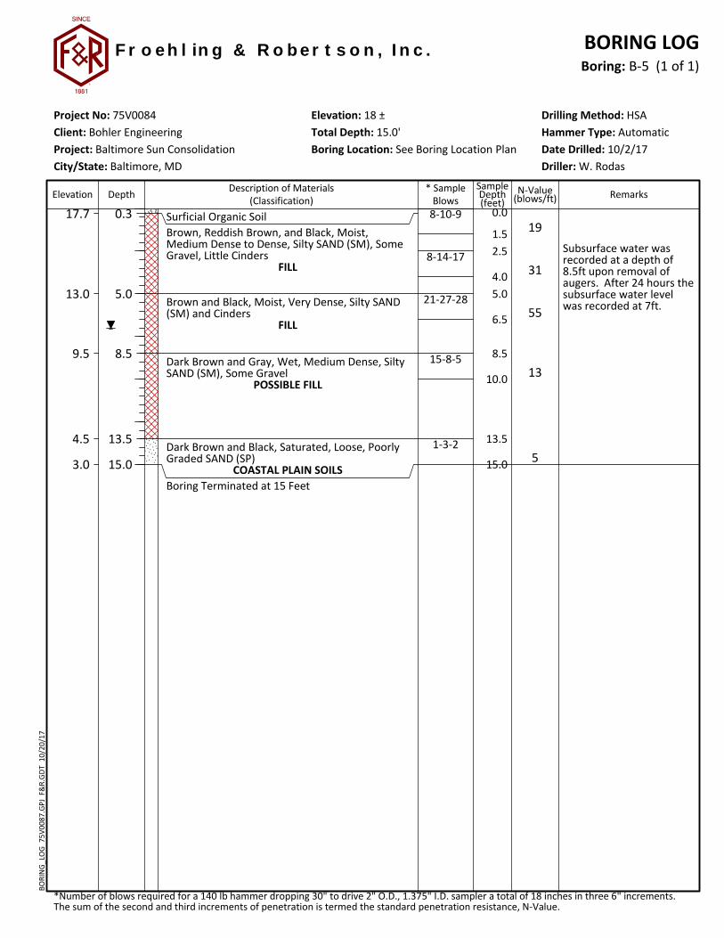
8-10-9
8-14-17
21-27-28
15-8-5
1-3-2
Surficial Organic SoilBrown, Reddish Brown, and Black, Moist,Medium Dense to Dense, Silty SAND (SM), SomeGravel, Little Cinders
FILL
Brown and Black, Moist, Very Dense, Silty SAND(SM) and Cinders
FILL
Dark Brown and Gray, Wet, Medium Dense, SiltySAND (SM), Some Gravel
POSSIBLE FILL
Dark Brown and Black, Saturated, Loose, PoorlyGraded SAND (SP)
COASTAL PLAIN SOILSBoring Terminated at 15 Feet
17.7
13.0
9.5
4.5
3.0
0.3
5.0
8.5
13.5
15.0
0.0
2.5
5.0
8.5
13.5
Subsurface water wasrecorded at a depth of8.5ft upon removal ofaugers. After 24 hours thesubsurface water levelwas recorded at 7ft.
19
31
55
13
5
Elevation: 18 ± Drilling Method: HSAHammer Type: Automatic
F r o e h l in g & R o b e r t s o n , I n c .
Client: Bohler Engineering
City/State: Baltimore, MDProject: Baltimore Sun Consolidation
*Number of blows required for a 140 lb hammer dropping 30" to drive 2" O.D., 1.375" I.D. sampler a total of 18 inches in three 6" increments.The sum of the second and third increments of penetration is termed the standard penetration resistance, N-Value.
Project No: 75V0084Total Depth: 15.0'Boring Location: See Boring Location Plan
BORING LOGBoring: B-5 (1 of 1)
N-Value(blows/ft)
Driller: W. Rodas
SampleDepth(feet)
Depth
R
* SampleBlowsElevation RemarksDescription of Materials
(Classification)
Date Drilled: 10/2/17
BORI
NG
_LO
G 7
5V00
87.G
PJ F
&R.
GD
T 1
0/20
/17

1.5
4.0
6.5
10.0
11-9-10
9-9-6
3-2-1
2-3-4
Surficial Organic SoilBrown and Black, Moist, Medium Dense, SiltySAND (SM), Trace Gravel, Trace Cinders
FILLBrown, Very Moist, Medium Dense, Fine SiltySAND (SM)
COASTAL PLAIN SOILSDark Brown, Wet, Soft, Sandy Lean CLAY (CL)
COASTAL PLAIN SOILS
Dark Gray, Wet, Loose, Poorly Graded SAND (SP)COASTAL PLAIN SOILS
Boring Terminated at 10 Feet
17.7
15.5
13.0
9.5
8.0
0.3
2.5
5.0
8.5
10.0
0.0
2.5
5.0
8.5
Subsurface water wasrecorded at a depth of6.5ft upon removal ofaugers. After 24 hours thesubsurface water levelwas recorded at 2.5ft.
19
15
3
7
Elevation: 18 ± Drilling Method: HSAHammer Type: Automatic
F r o e h l in g & R o b e r t s o n , I n c .
Client: Bohler Engineering
City/State: Baltimore, MDProject: Baltimore Sun Consolidation
*Number of blows required for a 140 lb hammer dropping 30" to drive 2" O.D., 1.375" I.D. sampler a total of 18 inches in three 6" increments.The sum of the second and third increments of penetration is termed the standard penetration resistance, N-Value.
Project No: 75V0084Total Depth: 10.0'Boring Location: See Boring Location Plan
BORING LOGBoring: B-6 (1 of 1)
N-Value(blows/ft)
Driller: W. Rodas
SampleDepth(feet)
Depth
R
* SampleBlowsElevation RemarksDescription of Materials
(Classification)
Date Drilled: 10/2/17
BORI
NG
_LO
G 7
5V00
87.G
PJ F
&R.
GD
T 1
0/20
/17

1.5
4.0
6.5
10.0
4-9-5
1-1-3
2-4-6
1-1-3
Surficial Organic SoilBrown and Black, Moist, Stiff, Sandy SILT (ML),Trace Gravel, Some Cinders
FILLDark Brown and Black, Moist, Soft, Sandy LeanCLAY (CL), Trace Cinders
FILLDark Gray, Very Moist, Loose, Poorly GradedSAND (SP)
COASTAL PLAIN SOILS
Dark Brown, Very Moist, Soft, Sandy Lean CLAY(CL)
COASTAL PLAIN SOILSBoring Terminated at 10 Feet
16.7
14.5
12.0
8.5
7.0
0.3
2.5
5.0
8.5
10.0
0.0
2.5
5.0
8.5
Subsurface water was notencountered duringdrilling or upon removal ofaugers. After 24 hours thesubsurface water levelwas recorded at 6ft.
14
4
10
4
Elevation: 17 ± Drilling Method: HSAHammer Type: Automatic
F r o e h l in g & R o b e r t s o n , I n c .
Client: Bohler Engineering
City/State: Baltimore, MDProject: Baltimore Sun Consolidation
*Number of blows required for a 140 lb hammer dropping 30" to drive 2" O.D., 1.375" I.D. sampler a total of 18 inches in three 6" increments.The sum of the second and third increments of penetration is termed the standard penetration resistance, N-Value.
Project No: 75V0084Total Depth: 10.0'Boring Location: See Boring Location Plan
BORING LOGBoring: B-7 (1 of 1)
N-Value(blows/ft)
Driller: W. Rodas
SampleDepth(feet)
Depth
R
* SampleBlowsElevation RemarksDescription of Materials
(Classification)
Date Drilled: 10/2/17
BORI
NG
_LO
G 7
5V00
87.G
PJ F
&R.
GD
T 1
0/20
/17

1.5
4.0
6.5
10.0
2-4-10
8-7-7
1-1-1
1-2-2
6 inches of Asphalt underlain by 6 inches ofSubbase GravelReddish Brown, Moist, Stiff, Gravelly Fat CLAY(CH)
FILLLight Brown, Very Moist, Medium Dense, SiltySAND (SM), Some Gravel
FILLDark Brown, Very Moist to Wet, Very Soft to Soft,Sandy Lean CLAY (CL)
COASTAL PLAIN SOILS
Boring Terminated at 10 Feet
19.0
17.5
15.0
10.0
1.0
2.5
5.0
10.0
0.0
2.5
5.0
8.5
Subsurface water was notencountered duringdrilling or upon removal ofaugers
14
14
2
4
Elevation: 20 ± Drilling Method: HSAHammer Type: Automatic
F r o e h l in g & R o b e r t s o n , I n c .
Client: Bohler Engineering
City/State: Baltimore, MDProject: Baltimore Sun Consolidation
*Number of blows required for a 140 lb hammer dropping 30" to drive 2" O.D., 1.375" I.D. sampler a total of 18 inches in three 6" increments.The sum of the second and third increments of penetration is termed the standard penetration resistance, N-Value.
Project No: 75V0084Total Depth: 10.0'Boring Location: See Boring Location Plan
BORING LOGBoring: B-8 (1 of 1)
N-Value(blows/ft)
Driller: W. Rodas
SampleDepth(feet)
Depth
R
* SampleBlowsElevation RemarksDescription of Materials
(Classification)
Date Drilled: 10/2/17
BORI
NG
_LO
G 7
5V00
87.G
PJ F
&R.
GD
T 1
0/20
/17

1.5
4.0
6.5
10.0
15.0
9-21-16
2-3-6
2-5-6
3-3-6
1-3-4
Surficial Organic SoilBrown and Black, Moist, Dense, Silty SAND (SM),Some Gravel, Some Cinders
FILLDark Brown and Black, Very Moist, Stiff, SandyLean CLAY (CL)
FILLBrown, Wet, Medium Dense, Silty SAND (SM)
FILL
Dark Brown, Dark Gray, and Black, Very Moist,Stiff to Medium Stiff, Sandy Lean CLAY (CL)
POSSIBLE FILL
Boring Terminated at 15 Feet
16.7
14.5
12.0
8.5
2.0
0.3
2.5
5.0
8.5
15.0
0.0
2.5
5.0
8.5
13.5
Subsurface water wasrecorded at a depth of11.5ft upon removal ofaugers. After 24 hours thesubsurface water levelwas recorded at 5.5ft.
Field infiltration testingwas performed at a depthof 3.5ft and recorded aninfiltration rate of 0.24inches/hour.
37
9
11
9
7
Elevation: 17 ± Drilling Method: HSAHammer Type: Automatic
F r o e h l in g & R o b e r t s o n , I n c .
Client: Bohler Engineering
City/State: Baltimore, MDProject: Baltimore Sun Consolidation
*Number of blows required for a 140 lb hammer dropping 30" to drive 2" O.D., 1.375" I.D. sampler a total of 18 inches in three 6" increments.The sum of the second and third increments of penetration is termed the standard penetration resistance, N-Value.
Project No: 75V0084Total Depth: 15.0'Boring Location: See Boring Location Plan
BORING LOGBoring: SWM-1 (1 of 1)
N-Value(blows/ft)
Driller: W. Rodas
SampleDepth(feet)
Depth
R
* SampleBlowsElevation RemarksDescription of Materials
(Classification)
Date Drilled: 10/2/17
BORI
NG
_LO
G 7
5V00
87.G
PJ F
&R.
GD
T 1
0/20
/17

1.5
4.0
6.5
10.0
15.0
2-4-8
5-5-5
3-3-3
1-1-1
3-2-3
Surficial Organic SoilBrown and Black, Moist, Medium Dense, SiltySAND (SM), Trace Gravel, Trace Cinders
FILLLight Brown, Very Moist to Wet, Medium Dense,Fine Silty SAND (SM)
COASTAL PLAIN SOILSDark Brown, Wet, Medium Stiff to Soft, SandyLean CLAY (CL)
COASTAL PLAIN SOILS
Dark Brown, Wet, Loose, Clayey SAND (SC)COASTAL PLAIN SOILS
18.7
16.5
14.0
5.5
4.0
0.3
2.5
5.0
13.5
15.0
0.0
2.5
5.0
8.5
13.5
Subsurface water wasrecorded at a depth of4.5ft upon removal ofaugers. After 24 hours thesubsurface water levelwas recorded at 3ft.
Field infiltration testingwas performed at a depthof 2ft and recorded aninfiltration rate of 0.36inches/hour.
12
10
6
2
5
Elevation: 19 ± Drilling Method: HSAHammer Type: Automatic
F r o e h l in g & R o b e r t s o n , I n c .
Client: Bohler Engineering
City/State: Baltimore, MDProject: Baltimore Sun Consolidation
*Number of blows required for a 140 lb hammer dropping 30" to drive 2" O.D., 1.375" I.D. sampler a total of 18 inches in three 6" increments.The sum of the second and third increments of penetration is termed the standard penetration resistance, N-Value.
Project No: 75V0084Total Depth: 15.0'Boring Location: See Boring Location Plan
BORING LOGBoring: SWM-2 (1 of 1)
N-Value(blows/ft)
Driller: W. Rodas
SampleDepth(feet)
Depth
R
* SampleBlowsElevation RemarksDescription of Materials
(Classification)
Date Drilled: 10/2/17
BORI
NG
_LO
G 7
5V00
87.G
PJ F
&R.
GD
T 1
0/20
/17

1.5
4.0
6.5
10.0
15.0
3-8-8
3-6-5
3-5-2
3-3-6
4-6-7
Surficial Organic SoilBrown and Gray, Moist, Medium Dense, SiltySAND (SM), Some Gravel
FILLBrown, Very Moist, Medium Dense, Silty SAND(SM)
FILLBrown and Black, Very Moist, Loose, ClayeySAND (SC), Some Cinders
FILL
Brown and Dark Brown, Wet to Saturated, Looseto Medium Dense, Silty SAND (SM)
COASTAL PLAIN SOILS
Boring Terminated at 15 Feet
18.7
16.5
14.0
10.5
4.0
0.3
2.5
5.0
8.5
15.0
0.0
2.5
5.0
8.5
13.5
Subsurface water wasrecorded at a depth of10.5ft upon removal ofaugers. After 24 hours thesubsurface water levelwas recorded at 3.5ft.
Field infiltration testingwas performed at a depthof 2ft and recorded aninfiltration rate of 0.48inches/hour.
16
11
7
9
13
Elevation: 19 ± Drilling Method: HSAHammer Type: Automatic
F r o e h l in g & R o b e r t s o n , I n c .
Client: Bohler Engineering
City/State: Baltimore, MDProject: Baltimore Sun Consolidation
*Number of blows required for a 140 lb hammer dropping 30" to drive 2" O.D., 1.375" I.D. sampler a total of 18 inches in three 6" increments.The sum of the second and third increments of penetration is termed the standard penetration resistance, N-Value.
Project No: 75V0084Total Depth: 15.0'Boring Location: See Boring Location Plan
BORING LOGBoring: SWM-3 (1 of 1)
N-Value(blows/ft)
Driller: W. Rodas
SampleDepth(feet)
Depth
R
* SampleBlowsElevation RemarksDescription of Materials
(Classification)
Date Drilled: 10/2/17
BORI
NG
_LO
G 7
5V00
87.G
PJ F
&R.
GD
T 1
0/20
/17

1.5
4.0
6.5
10.0
15.0
10-19-20
9-15-6
7-9-12
5-2-11
1-2-2
Surficial Organic SoilBrown, Reddish Brown, and Black, Moist, Denseto Medium Dense, Silty SAND (SM), Some Gravel
FILL
Tan, Very Moist, Medium Dense, Silty SAND(SM), Some Gravel
FILL
Brown and Black, Very Moist, Medium Dense,Silty SAND (SM), Some Cinders
FILL
Dark Gray, Wet, Soft, Sandy Lean CLAY (CL)COASTAL PLAIN SOILS
Boring Terminated at 15 Feet
18.7
14.0
10.5
5.5
4.0
0.3
5.0
8.5
13.5
15.0
0.0
2.5
5.0
8.5
13.5
Subsurface water wasrecorded at a depth of 8ftupon removal of augers.After 24 hours thesubsurface water levelwas recorded at 7.5ft.
Field infiltration testingwas performed at a depthof 5.5ft and recorded aninfiltration rate of 0.6inches/hour.
39
21
21
13
4
Elevation: 19 ± Drilling Method: HSAHammer Type: Automatic
F r o e h l in g & R o b e r t s o n , I n c .
Client: Bohler Engineering
City/State: Baltimore, MDProject: Baltimore Sun Consolidation
*Number of blows required for a 140 lb hammer dropping 30" to drive 2" O.D., 1.375" I.D. sampler a total of 18 inches in three 6" increments.The sum of the second and third increments of penetration is termed the standard penetration resistance, N-Value.
Project No: 75V0084Total Depth: 15.0'Boring Location: See Boring Location Plan
BORING LOGBoring: SWM-4 (1 of 1)
N-Value(blows/ft)
Driller: W. Rodas
SampleDepth(feet)
Depth
R
* SampleBlowsElevation RemarksDescription of Materials
(Classification)
Date Drilled: 10/2/17
BORI
NG
_LO
G 7
5V00
87.G
PJ F
&R.
GD
T 1
0/20
/17

1.5
4.0
6.5
10.0
15.0
4-8-7
1-1-3
1-1-2
3-5-5
1-2-2
Surficial Organic SoilBrown and Gray, Moist, Medium Dense, SiltySAND (SM), Some Gravel
FILLDark Gray, Very Moist to Wet, Soft, Sandy LeanCLAY (CL)
POSSIBLE FILL
Brown, Saturated, Loose, Silty SAND (SM)COASTAL PLAIN SOILS
Dark Gray, Very Moist, Soft, Sandy Lean CLAY(CL)
COASTAL PLAIN SOILSBoring Terminated at 15 Feet
14.7
12.5
6.5
1.5
0.0
0.3
2.5
8.5
13.5
15.0
0.0
2.5
5.0
8.5
13.5
Subsurface water wasrecorded at a depth of7.5ft upon removal ofaugers. After 24 hours thesubsurface water levelwas recorded at 6ft.
Field infiltration testingwas performed at a depthof 4ft and recorded aninfiltration rate of 0.6inches/hour.
15
4
3
10
4
Elevation: 15 ± Drilling Method: HSAHammer Type: Automatic
F r o e h l in g & R o b e r t s o n , I n c .
Client: Bohler Engineering
City/State: Baltimore, MDProject: Baltimore Sun Consolidation
*Number of blows required for a 140 lb hammer dropping 30" to drive 2" O.D., 1.375" I.D. sampler a total of 18 inches in three 6" increments.The sum of the second and third increments of penetration is termed the standard penetration resistance, N-Value.
Project No: 75V0084Total Depth: 15.0'Boring Location: See Boring Location Plan
BORING LOGBoring: SWM-5 (1 of 1)
N-Value(blows/ft)
Driller: W. Rodas
SampleDepth(feet)
Depth
R
* SampleBlowsElevation RemarksDescription of Materials
(Classification)
Date Drilled: 10/2/17
BORI
NG
_LO
G 7
5V00
87.G
PJ F
&R.
GD
T 1
0/20
/17

Boring No.Sample
Depth
Natural
Moisture % Sand %Silt % Clay USDA Classification
SWM-1 2.5-4ft 18.4 50 35.7 14.3 LOAM
FROEHLING & ROBERTSON, INC.
Engineering Stability Since 1881
10626 York Road, Suites C-D Cockeysville, Maryland 21030
T 410.825.4131 I F 410.321.7384
USDA Textural Triangle
Client: Bohler Engineering
Project: Baltimore Sun Consolidation
F&R Project No. 75V0084
Date: Oct., 2017

Boring No.Sample
Depth
Natural
Moisture % Sand %Silt % Clay USDA Classification
SWM-2 2.5-4ft 26.1 86.5 8.1 5.4 Loamy SAND
FROEHLING & ROBERTSON, INC.
Engineering Stability Since 1881
10626 York Road, Suites C-D Cockeysville, Maryland 21030
T 410.825.4131 I F 410.321.7384
USDA Textural Triangle
Client: Bohler Engineering
Project: Baltimore Sun Consolidation
F&R Project No. 75V0084
Date: Oct., 2017

Boring No.Sample
Depth
Natural
Moisture % Sand %Silt % Clay USDA Classification
SWM-3 2.5-4ft 16.1 79 7.3 13.7 Sandy LOAM
FROEHLING & ROBERTSON, INC.
Engineering Stability Since 1881
10626 York Road, Suites C-D Cockeysville, Maryland 21030
T 410.825.4131 I F 410.321.7384
USDA Textural Triangle
Client: Bohler Engineering
Project: Baltimore Sun Consolidation
F&R Project No. 75V0084
Date: Oct., 2017

Boring No.Sample
Depth
Natural
Moisture % Sand %Silt % Clay USDA Classification
SWM-4 8.5-10ft 35.2 68.5 24.5 6.9 Sandy LOAM
FROEHLING & ROBERTSON, INC.
Engineering Stability Since 1881
10626 York Road, Suites C-D Cockeysville, Maryland 21030
T 410.825.4131 I F 410.321.7384
USDA Textural Triangle
Client: Bohler Engineering
Project: Baltimore Sun Consolidation
F&R Project No. 75V0084
Date: Oct., 2017

Boring No.Sample
Depth
Natural
Moisture % Sand %Silt % Clay USDA Classification
SWM-5 5-6.5ft 27.2 16.2 52.5 31.3 Silty Clay LOAM
FROEHLING & ROBERTSON, INC.
Engineering Stability Since 1881
10626 York Road, Suites C-D Cockeysville, Maryland 21030
T 410.825.4131 I F 410.321.7384
USDA Textural Triangle
Client: Bohler Engineering
Project: Baltimore Sun Consolidation
F&R Project No. 75V0084
Date: Oct., 2017

Bohler Engineering Baltimore Sun Consolidation – Baltimore, MD
F&R Project No. 75V0084 October 20, 2017
APPENDIX III