Report No. SA-TR20-2906 POWER AND SPACE REQUIREMENTS …
50
USADAC TECHNICAL LIBRARY MAST ON -rf-u &. ¥ i TECHNICAL ^ LIBRARY AD Report No. SA-TR20-2906 POWER AND SPACE REQUIREMENTS FOR SIMULATION OF MACHINE GUN MOUNTS Technical Report David Gelfond Author Date 1 September 1966 SPRINGFIELD ARMORY SPRINGFIELD, MASSACHUSETTS **
Transcript of Report No. SA-TR20-2906 POWER AND SPACE REQUIREMENTS …

USADAC TECHNICAL LIBRARY MAST ON
-rf-u &.
¥ i
TECHNICAL ^ LIBRARY
AD
Report No. SA-TR20-2906
POWER AND SPACE REQUIREMENTS FOR SIMULATION OF
MACHINE GUN MOUNTS
Technical Report
David Gelfond
Author
Date 1 September 1966
SPRINGFIELD ARMORY SPRINGFIELD, MASSACHUSETTS
**

AVAILABILITY NOTICE.
Qualified requesters may obtain copies of this report from the Defense Documentation Center, Cameron Station, Alexandria, Virginia 22314.
Other requesters may purchase copies of this report from the Clearinghouse, Department of Commerce, Springfield, Virginia 22151.
DISCLAIMERS.
The findings in this report are not to be construed as an official Department of the Army position unless so designated by other authorized documents.
The citation in this report of trade names and manufacturers does not constitute official indorsement or approval.
DISPOSITION INSTRUCTIONS.
This report is to be destroyed when it is no longer needed. It is not to be returned to the originator.
! ? I

Report: SA-TR20-2906
Da te; 1 September 1966
AMCMS Code: 5142.12.11209.07
POWER AND SPACE REQUIREMENTS FOR SIMULATION OF MACHINE GUN MOUNTS
Technical Report
David Gelfond
DA Project Title: Development of Aircraft Gun Type Subsystems
DA Project: 11-5-50206-01-M1-M6
This TECHNICAL REPORT, to the extent known, does not contain any patentable material, copyrighted and/or copyrightable material.
DISTRIBUTION OF THIS DOCUMENT IS UNLIMITED.
REPORT SA-TR20-2906
ABSTRACT
The electric power and site requirements are established for a single degree-of-motion- freedom machine gun mount simulator capable of supporting all automatic small arms through 30 millimeter weapons. The concept of using an electromechanical servomechanism to simulate the mass, stiffness, and damping characteristics of the gun mount is shown analytically to be feasible. Experimental verification of the simulation concept is demonstrated by burst-firing of a 5.56 milli- meter machine gun on a scale model.
(i)
REPORT SA-TR20-2906
CONTENTS Page
Abstract (i)
Subject 1
Objective 1
Conclusions 1
Recommendations 1
Introduction 2
Principles of Operation . 3
Motor Characteristics 8
Electric Power Requirements 22
Physical Size of Components 23
APPENDICES
A - Results of Single-Shot Firing (Typical Record) 27
B - Results of Automatic Firing (Typical Record) 32
C - Distribution 37
(il)
~^~1~
REPORT SA-TR20-2906
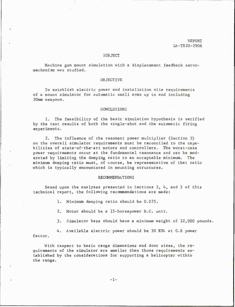
SUBJECT
Machine gun mount simulation with a displacement feedback servo- mechanism was studied.
OBJECTIVE
To establish electric power and installation site requirements of a mount simulator for automatic small arms up to and including 30mm weapons.
CONCLUSIONS
1. The feasibility of the basic simulation hypothesis is verified by the test results of both the single-shot and the automatic firing experiments.
2. The influence of the resonant power multiplier (Section 3) on the overall simulator requirements must be reconciled to the capa- bilities of state-of-the-art motors and controllers. The worst-case power requirements occur at the fundamental resonance and can be mod- erated by limiting the damping ratio to an acceptable minimum. The minimum damping ratio must, of course, be representative of that ratio which is typically encountered in mounting structures.
RECOMMENDATIONS
Based upon the analyses presented in Sections 3, 4, and 5 of this technical report, the following recommendations are made:
factor.
1. Minimum damping ratio should be 0.075.
2. Motor should be a 15-horsepower D.C. unit.
3. Simulator base should have a minimum weight of 32,000 pounds.
4. Available electric power should be 30 KVA at 0.8 power
With respect to basic range dimensions and door sizes, the re- quirements of the simulator are smaller than those requirements es- tablished by the considerations for supporting a helicopter within the range.

REPORT SA-TR20-2906
1. INTRODUCTION
It is a well-established fact that all automatic weapons will exhibit a performance sensitivity to their mounting conditions. The sensitivity of a weapon to its mounting conditions may manifest itself as change in recoil force only, or, in the extreme, as a complete failure to function. Therefore, it becomes necessary during weapon development to investigate weapon-mount compatibility for installations where the potential mount natural frequencies are in the range of the first several multiples of the weapon firing rate. Over the years, two basic systems, families of helical springs or variable length beams, have been used to simulate weapon mounts. Both of the afore-mentioned approaches to simulation are physically cumbersome, lengthy in the setup and adjustment time, and only rarely have incorporated control over damping ratio. In 1962, scientists at Springfield Armory began a search for simulation techniques that would permit rapid adjustment of mount spring rate and independent control of the damping ratio. The most promising method for mount simulation, that of disturbing a position feedback servosystem at its mechanical output point by the weapon recoil force, has been examined analytically and its feasibility demonstrated experimentally.

REPORT SA-TR20-2906
2. PRINCIPLES OF OPERATION
a. The Springfield Armory weapon mount simulator concept,depicted in Figure 1, is based upon the hypothesis that a position feedback servo- system disturbed at its mechanical output point exhibits the same response as a classical mass-spring-dashpot network. The unique features of the Springfield Armory concept are in the ease of adjustment of spring rate and independent control of the damping ratio. It will be shown below that the spring rate is a function solely of the time-invariant servoloop gain terms.
From Figure 2:
X(s) s4^+}^(Kb+icv*os+a£s- FCs> When F(s) . - , then by the final value theorem Equation 2-1 become«
v. ci^Lf Kt Ka
The spring rate, K, is given by
2-1
2-2
K = F_= Kt Ko, 2-3 X " (V n) *
The factored form of 2-1 is
V (O _ (rn)Z(H-T)/jT p. 2-4
-3-

REPORT SA-TR20-2906
u C <D j V X o u <o m
-" .0 co (0 0)
•H <D Q tu
H W u §
I g
01
Eo
-4-

c co
REPORT SA-TR20-2906
S u
g (0
•w a. ■u CO
o •a •^ >-• M 4J 4J ffl C o
f-H • 3
00 I «1 h
o c
■ to o
c 0) 4-1 01 i-« •^ u <0 3 •a u a. <0 3 u a* II 14-1 CO So 4J 01 h «i CO 1-1
(0 a o a * •o u 0) B o 4-1 DO en
c 1-1 m • U u u o y-i CJ o o O a •-4 u It) u u 4-1 3 ^ o <-l o o O o. u (X X X 2 3 S o
X 3 It n II II
ii ■ ■ ^-\ ^ ^-s /-> CO o> ■ CO
CO s^ v^ •*~* N_^
* H tn H • a> a> X
CO
'\
o ä CN
u a 01 c Ui
CO 4J CO 4J g S,
•H c CO ^J i-i 4J 4-1 CO c ft, tu, U e 4-1 0 0) CO 0) O J c 4-1 c
1-1 CO o * 52J CO 1 C o CJ O 3 14-1 o 2 H i-i o CJ 14-4 rn •o 1 g •O
CO 4J 01 01 *J Ui c 3 <U 3 O 01 cr Jrf IM a. u •w g M o c s ■u O CO >>
T^ CO B 4-1 XI 4J 00 U 1-1
<u i-i u u 8 o 4J u CO 0 o n co 3 4-1 4J 4-1 .-1 o 2 0 o o 01
Cx ü H X X >
c 4-1
(A
H
CO ■—t
fa * tf >
-3-

REFORT SA-TR20-2906
2. PRINCIPLES OF OPERATION - Continued
The time response for F(s) ■ I Is 2-5
„ft). fri)*I u^e*£W)/1-2Tfu;, + TV Kt K«. Ci-f *;,/8 U-2bTfW,+ b*T\A>> ,)
/2
+ Crn^I_ TCb-l) e"*/"T
Kt Ko. 0-2bT/W,+ bzT2W,2)
' 1-TfUJ, i-bT/w,
T^.005, ^£.oS a-4 W, = 200 tken. I.f^b-I
and 2-5 simplifies to
, .Z T , . _ £ lv\t yft)r HIW, e f ^u,±
Substituting 2-3 into 2-6 gives
Equation 2-7 is identical with the response equation for a mass- spring-dashpot network subjected to an impulse forcing function.
The effect of the velocity feedback can best be seen by applying the Routh-Hurwitz criteria for stability to the characteristic equation of the
servoloop.
-6-
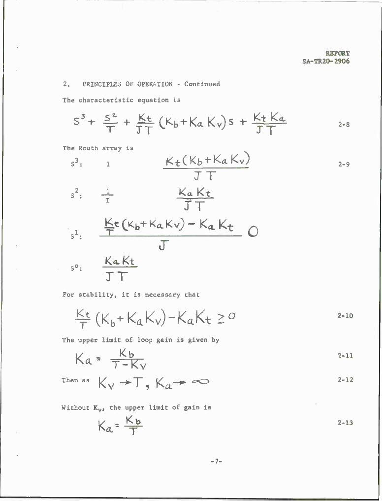
2. PRINCIPLES OF OPERATION - Continued
The characteristic equation is
s3+ 4^ + ||rC
l<b+K<lKv)s+-^=^ J T »* I
S°! K<LK±
Without Ky, the upper limit of gain is
V - *±
REPORT SA-TR20-2906
2-8
The Routh array is
JT
JT ^tCvCb^Ka.Kv)-K<<,Kt n
2-10
JT For stability, it is necessary that
^(Kb+KaKv)-KJ<t>0
The upper limit of loop gain is given by
W - *b Vll
2-13
•7-

2-15
REPORT SA-TR20-2906
2. PRINCIPLES OF OPERATION - Continued
By comparison of Equations 2-12 and 2-13, it is seen that velocity feedback is necessary to obtain the required stability (damping ratio) at the very large values of loop gain that must be used to provide the necessary range of spring rates.
To fulfill the necessary simulation conditions on mass, the total reflected moment-of-inertia must equal the total translation 1 mass. The magnitude of the reflected inertia is controlled by the total gear ratio rn.
The total moment-of-inertia term J in Equation 2-1 is
2 J s J motor + J gear + (rn) M weapon 2-14
If J gear^<(rn)2 M weapon, then
J ■ J motor + (rn)2 M weapon a (rn)2 JMweapon"r*M mount
The gear ratio is given by
rn z (J motor)1/2 2-16 M mount
b. A model of the mount simulator was fabricated to substantiate experimentaly the basic hypothesis. The model was tested initially with single-shot firings of ammunition having a 3 pound-second impulse and then tested with automatic firing of ammunition having approximately 1.0 pound- second impulse. In both cases, good agreement was obtained between actual and theoretical values of displacement and natural frequency. Parameter values, test results, and typical time-displacement curves for the single- shot and for automatic firing tests are given in Appendices A and B.
3. MOTOR CHARACTERISTICS
a. The maximum motor torque and speed requirements are, respectively, functions of the peak recoil displacement and peak counterrecoil velocity of the weapon, and the overall gear ratio that provides the conversion from rotary to translational motion. The motor power requirement can be determined from the basic system parameters of mass, stiffness, damping, and the forcing function magnitude and waveform.

-T-i T'lr
SA-TR20-2906
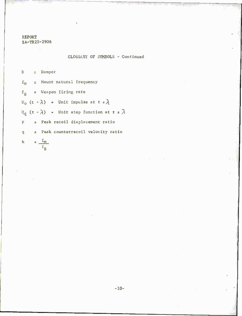
GLOSSARY OF SYMBOLS
T ■ Motor torque
Tp ■ Peak motor torque
n ■ Gear ratio
r ■ Radius of last gear
I ■ Impulse
K 3 Spring rate
M = Mass
J = Moment-of-inertia
f S Damping ratio
"l ■
f K \ 1/2 Undamped natural frequency a \~~frj
w I Damped natural frequency »UK ^1 "9 )
X s Displacement
XRP = Peak recoil displacement
xc- " c RP Peak counterrecoil velocity
• X 8 Velocity
b ■ Weighting constant
W ■ Motor speed
WP •» Peak motor speed
s = Laplace operator
c ■ 1
550
t ■ time
HP S Horsepower
REPORT SA-TR20-2906
GLOSSARY OF SYMBOLS - Continued
B r Damper
fm = Mount natural frequency
fg r Weapon firing rate
U0 (t -A) ■ Unit impulse at t s\
U., (t - PO - Unit step function at t s "X
P = Peak recoil displacement ratio
q = Peak counterrecoil velocity ratio
k 3 f m . fg
■10-

REPORT SA-TR20-2906
3. MOTOR CHARACTERISTICS - Continued
MOTOR
FORCE
Generalized Mechanical Coupling
At peak displacement, the motor torque is
T s Prn s rnK XRP
At the maximum counterrecoil velocity, the motor speed is
Wp s Xc-j^
3-1
3-2
rn
The peak motor power is
Tp Wp - KXRP XC^ 3-3
General Torque-Speed Characteristics
The motor horsepower requirement is given by
HP • cWT
-11-
3-4

REPORT SA-TR20-2906
3. MOTOR CHARACTERISTICS - Continued
From the general torque-speed characteristic,
T = Tp (1 - g->
From 3-4 and 3-5,
HP W C Tp W(l - £-)
Differentiating 3-6 and setting equal to zero, gives
d HP . C Tp (1 - 2W) dW Wr
W = Wg
Substituting 3-7 into 3-6 gives maximum horsepower
HP max s c Tp W.
From 3-3 and 3-8,
HP maximum = cK X^p Xc-^p
3-5
3-6
3-7
3-8
3-9
b. To establish the magnitude of the motor horsepower, two different simulation requirements will be considered.
Case I: Ideal Impulse Forcing Function
I RECOIL
I COUNTER
RECOIL
MOTOR PRIVES LOAD
MAXIMUM VELOCITY
Generalized Time Response, X(b)
-12-

REPORT SA-TR20-2906
3. MOTOR CHARACTERISTICS - Continued
The impulse response is
X(t) = (KM)'/2
Xj?p = ;-* (KM) '/Z _ ^tJn-t f
*W = M e cos W, t
C-R P
From Equations 3-9, 3-11, and 3-13
HpMAXIMOMr ^J2 J__ e -3f?£
A- M3/z
3-10
3-11
3-12
3-13
3-14
Equation 3-14 represents only the single-shot power requirement. The effect of resonance will be determined below for various ratios of mount natural frequency to weapon firing rate.
When fm/fg ■ 1
1 «56, 4-?6,
n 211 w.
Generalized Repetitive Impulse Input
-13-

REPORT SA-TR20-2906
3. MOTOR CHARACTERISTICS - Continued
Applying the laws of superposition,
oO
X£^ 2 Uo(t-X)x(t),^«X=(4*v-3)iWi 3-.5 aS ' ,/VA « MUKA6e<? OF SHOTS
ANC? X(t) IS GIVEN IN 3-lO
Expanding the series,
— € TT — 5 V " z' "\ 3-16
Rewriting Equation 3-16,
yWr-L-, e 2 >" e ) A--»H-I A KP (KM)l/2 ^o
Equation 3-17 reduces to
-fV* A RP "(KM)'/2 i-e~2f * The displacement multiplier
(oo) XRP I
3-17
3-18
D - ^ - ! ^ 3-19
3-20
-14-

REPORT SA-TR20-2906
3. MOTOR CHARACTERISTICS - Continued
Expanding Equation 3-20 gives
X Coo) . _1_ Q +e ^e + il<II| 3-21
Equation 3-21 reduces to
0 (CX>) = X. -J __ 3-22
The velocity multiplier
VC°°> , 3-23
From Equations 3-19 and 3-23, it is seen that q - p; therefore, the power multiplier is
P* ' Ci-e^f*)* 3-24
When fm . 2 fg
Then by steps of Equations 3-16 through 3-18
J p . L 3-26
When ^»m p J 3-27
15-

REPORT SA-TR20-2906
3. MOTOR CHARACTERISTICS - Continued
Generalizing the multiplier,
Then the upper bound of horsepower is
HP = 4-M J/e
3-28
3-29
Case II: Time-Distributed Forcing Function
X *. Generalized Forcing Function
The system single-shot response is given by
X(t> = UiCt) r(t)-U,Ct-X) r(t)
MOTOR PRWES LOAP
MAXIMUM VELOCITY
COUNTER RECOIL
Single-Shot Response
-16-
3-30
— *

REPORT SA-TR20-2906
3. MOTOR CHARACTERISTICS - Continued
The peak displacement is given by
Xnp-.-J [i + e" 1 , wHei?e X = yo;,
The peak velocity is given by
Xc- RP (KM) Vz e [, + e '] From Equations 3-9, 3-31, and 3-32,
HP= c FZ e -fVa 4(KM) '/2
i + e ~fri2
J
3-31
3-32
3-33
Equation 3-33 represents only the single-shot power requirement. The effect of resonance will be determined below.
For burst-firing, the forcing function is
A > f zy Y 3> f
When *m
Generalized Repetitive Time-Distributed Impulse
si, A=% ANO Y-z/*>\
•17-

number of shots 3-34
REPORT SA-TR20-2906
3. MOTOR CHARACTERISTICS - Continued
and Xr r X(t) at t r (2m-l)
Xr= VK e^^O+e^^e-^
- 2/*ff -/*ir\ °° -2/ a
3-35
Wl-TT 3-36
3-37
3-38
P = '-gg-tr 3°9
-18-

REPORT SA-TR20-2906
3. MOTOR CHARACTERISTICS - Continued
|Xc_.P|-|xc.RJ(4-^w.] >:c.R=XCi:)ATt<4M-.)^w
3-40
voHEf?E
l^cJ-cli</ae E|«*(^0|+(ica)*e«T(4«)
I 3-A3 fr = TäTTfi " i-e '
in Case II. Just as in Case I, q . P snd the po»er .»lUpHer becomes Pz
3-41
When £m = 2, ' A = uJ a^l<^ V UO
3-44 XRP(«)- 2 (X,[(* *-*)%]
• 19-

REPORT SA-TR20-2906
3. MOTOR CHARACTERISTICS - Continued
P= i-e-4<f~r
The multiplier can be generalized to
3-45
3-46
1 _y *, k = i2 = 1, 2, 3, etc. 3-47
And then the upper bound of horsepower is
3-48
c. To establish values of motor horsepower, parameters representing typical limits of small arms ammunition and weapon mass will be considered. Also, various values of structural damping representing typically encoun- tered values will be assumed to provide a range of resonance multipliers. The specific values of spring rates that will be assumed are those that will make the mount natural frequencies represent the fundamental, second, and third harmonics of the firing rate.
TABLE I
Resonant Power Mult tpl ier , P2
K .05 .075 .1
l 13.7 7.1 4.6
2 4.6 2.7 1.96
3 2.7 1.73 1.38
Case I: Ideal Impulse Forcing Function
Let: M s 10 slugs I > 30 lb-sec
9 = .05, .075, .1 k - 1, 2, 3
fg > 10/sec
the stiffness K, will be taken as
-20-

REPORT SA-TR2O-2906
3. MOTOR CHARACTERISTICS - Continued
K - kW,1 M 3-49
From Equations 3-29 and 3-49, the upper bound of motor horsepower is
9 -3/Vr 3-50 - ci2k \JJI e T p2
HP 4M
2 -3;v2 ■ 30* x 10x6.28xke 2200 x 10
. 2.57k i'W p2
P1
TABLE II
Motor Hor sepower for Case I
^ .05 .075 .1
1 27.8 12.75 7.4
2 18.7 9.63 6.26
3 16.3 9.4 6.65
Case II: Reduced Mass and Impulse
Let M z 3 slugs 1=6 lb-sec
TABLE III
Motor Horsepower for Case II
*\f -05 .075 .1
1 3.73 1.70 1.0
2 2.53 1.29 .85
3 2.18 1.25 .9
-21-
REPORT SA-TR20-2906
3. MOTOR CHARACTERISTICS - Continued
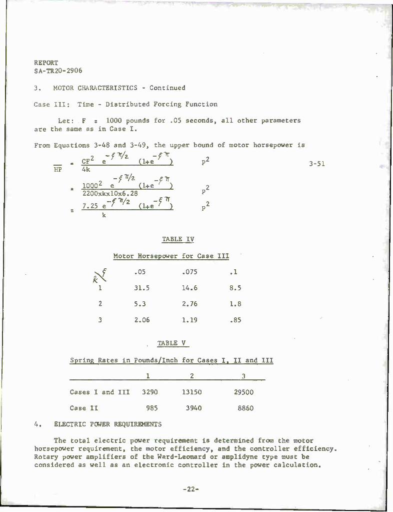
Case III: Time - Distributed Forcing Function
Let: F s 1000 pounds for .05 seconds, all other parameters are the same as in Case I.
From Equations 3-48 and 3-49, the upper bound of motor horsepower is
n2
HP CF2 e"
-f«A (1+e"
■'*)
4k
10002 e (1+e" ■n, 2200xkx10x6.2*
7.25 e'fV*
1
(1+e" -^
3-51
P2
P2
TABLE IV
Motor Hors epower for Case III
tf
.05 .075 .1
1 31.5 14.6 8.5
2 5.3 2.76 1.8
3 2.06
TABLE
1.19
V
.85
Spring Rates in Pounds/Inch for Cases I, II and III
1 2 3
Cases I and III 3290 13150 29500
Case II 985 3940 8860
4. ELECTRIC POWER REQUIREMENTS
The total electric power requirement is determined from the motor horsepower requirement, the motor efficiency, and the controller efficiency. Rotary power amplifiers of the Ward-Leonard or amplidyne type must be considered as well as an electronic controller in the power calculation.
-22-

REPORT SA-TR20-2906
4. ELECTRIC POWER REQUIREMENTS - Continued
Motor Watts - ^-^ - i^l5 s 14>000 4-1
Motor Eff. «8
Electronic Controller Input « Motor Watta . *&&& -- 15,500 4-2 Controller Eff. *9
Two-Stage Rotary Amplifier • ^Qg0 ■ 23,300 watts 4-3
For the two-stage rotary amplifier, the prime mover is generally a three-phase motor with a 0.8 power factor. Therefore, the KVA require- ment is
KVA * Si , iLi . 29.2 4-4 Power factor .8
5. PHYSICAL SIZE OF COMPONENTS
Motor Weight: Approximately 320 pounds
Motor Dimensions: Length, 20 inches Height, 14 inches Depth, 24 inches
Controller Weight: 500 pounds (total)
Operator's Console: Length, 5 feet Height, 4 feet Depth, 3 feet
Power Units: Length, 4 feet Height, 6 feet Depth, 2 feet
Simulator Base: The simulator base is considered as an isolated mass large enough in value so that it does not affect the frequency of oscillation or amplitude of displacement of the simulator.
-23-

REPORT SA-TR20-2906
5. PHYSICAL SIZE OF COMPONENTS - Continued
Generalized Installation Dynamics
[M, s *+ Bs+ K] X,(S) - [K+ BS] X2^S) = R3) 5-1
-[Kt-Bs]x1Ö)+[M2s2+Bs+K]X2(s) =0 5-2
X,^-X2(s) = Mz Fcs>
Fo«. M? = löoM, I FCS)
X,(s) -XzCs)- ».one" wlh
FOR M2 = C>0 S-4- BECOMES
Xtf>-£ F<s)
YS2+!^'
5-3
5-4
5-5
•24-

REPORT SA-TR20-2906
5. PHYSICAL SIZE OF COMPONENTS - Continued
By comparison of Equations 5-4 and 5-5, It ia seen that, for M2 ■ 100 M, there is a reduction in natural frequency of 0.5 per cent and in amplitude of 1.0 per cent. Considering the above Indicated differences as negligible leads to the conclusion that the minimum acceptable simulator base weight is 100 times the weight of the weapon and mount.
Simulator Base Weight: 32,000 pounds
Working Surface: 7 feet by 7 feet
Height Above Floor: 2 feet, 6 inches
Minimum Depth Below Floor: 3 feet
25-

REPORT SA-TR2O-2906 APPENDICES
A - Results of Single-Shot Firing (Typical Record)
B - Results of Automatic Firing (Typical Record)
C - Distribution
•26-
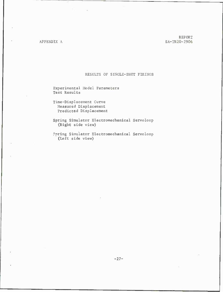
REPORT APPENDIX A SA-TR20-2906
RESULTS OF SINGLE-SHOT FIRINGS
Experimental Model Parameters Test Results
Time-Displacement Curve Measured Displacement Predicted Displacement
Spring Simulator Electromechanical Servoloop (Right side view)
Spring Simulator Electromechanical Servoloop (Left side view)
■27-

REPORT SA-TR20-2906 APPENDIX A
EXPERIMENTAL MODEL PARAMETERS
J » .03 lb-ft-sec2
Kt ■ .158 lb-ft/volt
Kb = 1.56 volt/rad/sec
Ka « 20, 50, 100, 200
r > 1.125 in.
I = 3.0 lb-sec
T = .004 sec
TEST RESULTS
Spring
Ütl
30 lb/in.
75
150
300
Predicted Displacement
.605 in.
.47
.375
.300
Measured Displacement
.70 in.
.55
.40
.30
-28-

APPENDIX A
REPORT SA-TR20-2906
c
CO
a 09
•o ft) p 3 01
CO
S
CM
•o u o
•H •a <u u (X,
s' ^
—y—
»i —ß~~ • V ♦<•
N> ^> CT) rN „"»
V jfN «i V4 o r 2i 0
V '> W- Lx)f
^S
0 o
0
OBs

REPORT SA-TR20-2906
APPENDIX A
u 3 u
u CO 0) H
a o o
« o
•r-l
S o
o
o V
«-4 w
o
00 c
•H u a
CO

APPENDIX A
REPORT SA-TR20-2906
v
3 a
H a §
to
.-H
J I
o a)
O
I to
c •w
s. to
REPORT SA-TR20-2906 APPENDIX B
Test Conditions
Typical Time-Displacement Curves
Photographs
-32-

REPORT APPENDIX B SA-TR20-2906
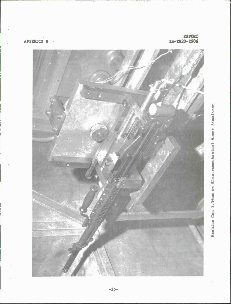
Automatic firing tests were conducted to demonstrate that a reasonable level of mount dynamics similitude can be obtained with an unsophisticated model. The level of similitude that was obtained can be seen by comparing the burst firing time-displacement curves of the simulator with those curves obtained from the four leaf cantilever beam mount. The observable differences in the time-displacement records are related primarily to the test-to-test variation in weapon rate-of-fire and to the differences in damping forces. The cantilever beam mount exhibits a viscous friction damping, whereas the simulator damping is composed of both viscous and coulomb frictions. The coulomb friction portion of simulator damping is related to the motor commutator brush and gear antibacklash loads.
Test Conditions:
Weapon: 5.56mm MG
Ammo Impulse: 1.0 pound-second (nominal)
Mount Stiffness: 1800 pounds/inch
Total Mass: 3.2 slugs
■33-

REPORT SA-TR20-2906
)
CO
z o ö
o E Q_ e oo
in r».
I 3 »3
lil
}
> a: => o
o o
SS — ^ Q O
S O (- O
SS CO CO
OS ^T UJ >
o
O o
o
-34-
APPENDIX B
c_>
C_>
Q_ O o
oo
a_ uj
?< « z
OS o
^3
o
o o
APPENDIX B SA-TR20-2906
u o
I CO
I c
o
u u
w
§
in
1 e
U
■35-

REPORT SA-TR20-2906 APPENDIX B
4) U
2 ->
u
B 8 u >
u c
I in
c 3 O dl c
-36-
APPENDIX C
DISTRIBUTION
Department of Defense
Washington, D.C. 20310
Commanding General U.S. Army Materiel Command ATTN: AMCRD (l)
AMCRD-R (I) Bldg T-7, Rm 817 Washington, D.C. 20315
Commanding General U.S. Army Weapons Command ATTN: AMSWE-RD (2)
AMSWB-PP (1) Rock Island, Illinois 61201
Commanding General U.S. Army Aviation Materiel Command St. Louis, Missouri 63166
Commanding General U.S. Army Electronics Command ATTN: AMSEL-RE Ft. Monmouth, New Jersey 07703
Commanding General U.S. Army Missile Command ATTN: AMSMI-RB, Redstone Scientific Information Center Redstone Arsenal, Alabama 35809
Commanding General U.S. Army Mobility Command ATTN: AMSMO-RDS 28251 Van Dyke Avenue Warren, Michigan 48090
Commanding General Edgewood Arsenal ATTN: R&D Laboratory Edgewood, Maryland 21010
REPORT SA-TR20-2906
Copies
1 StMr
2 S-?»-£-
3 ^S&H-tr
i «5-f^r-
i Sen*-
i se hT
i stm?-
l Stht-
■37-

REPORT SA-TR20-2906 APPENDIX B
DISTRIBUTION - Continued
Copies
Commanding General Q 2 U.S. Army Research Office O^"^— Office Chief Research and Development ATTN: Physical Sciences Division 3045 Columbia Pike Arlington, Virginia 22204
Commanding General OQ__Vl <-r^ 1 U.S. Army Munitions Command ■.s" ATTN: AMSMU-RE Dover, New Jersey 07801
Commanding General 1 U.S. Army Na tick Laboratories O^W"£"~ Kansas Street Natick, Massachusetts 01762
Commanding Officer ^dVI-k ATTN: Technical Library, Bldg 313 Aberdeen Proving Ground, Maryland 21005
Commanding General 1 U.S. Army Tank-Automotive Center ^n^^~ 28251 Van Dyke Avenue Warren, Michigan 48090
Commanding General 1 White Sands Missile Range <r * irtr- ATTN: STEWS -° ^ ** Las Cruces, New Mexico 88002
Commanding Officer 1 Detroit Arsenal ^Q tytT Warren, Michigan 48090
Commanding Officer 2 U.S.'Army Materials Research Agency C? f) wt? ATTN: TIC (1) •-> * "
AMXMR-ATL (1) Watertown, Massachusetts 02172
-38-
APPENDIX C REPORT 8A-TR20-2906
DISTRIBUTION - Continued
Copies
Commanding Officer 1 S^W't^ U.S. Army Electronics Research and Development Laboratories Ft. Monmouth, New Jersey 07703
Commanding Officer 1 S&lr)~tsr
U.S. Army Ballistics Research Laboratories Aberdeen Proving Ground, Maryland 21005
Director 1 U.S. Army Coating - Chemical Laboratory ~S& /?•)£- Aberdeen Proving Ground, Maryland 21005
Chief of Research and Development 1 U.S. Army Research and Development Liaison Group ^> £ H "£~ APO 757 New York, N. Y. 10000
Chief, Office of Naval Research 1 ATTN: Code 423 SdHtr Department of the Navy Washington, D. C. 20315
Chief, Bureau of Naval Weapons 1 £-. Department of the Navy ^c/flfc- Washington, D. C. 20315
Director 1 Naval Research Laboratory <r p L,-f- ATTN: Technical Information Officer Anacostia Station Washington, D. C. 20019
Commander 1 U.S. Naval Ordnance Test Station <ZP ft-£- ATTN: Technical Library ~* 'T" China Lake, California 96105
Commanding General 2 <^ * ^s Wright Air Development Division ATTN: MAE Wright-Patteraon Air Force Base, Ohio 45433
-39-
REPORT SA-TR20-2906 DISTRIBUTION • Continued APPENDIX C
Copie»
Commanding Officer Sfi fr & 1 Harry Diamond Laboratories ATTN: AMXDO-TIB Connecticut Avenue and Van Ness Street, N.W. Washington, D. C. 20438
Commanding Officer Defense Documentation Center Cameron Station, Bldg 5 5010 Duke Street Alexandria, Virginia 22314
Commanding Officer Rock Island Arsenal ATTN: SWERI-RD Rock Island, Illinois 61202
Commanding Officer Watervliet Arsenal ATTN: SWEWV-RD Watervliet, New York
SOM^
Savi-tr-
sen* 12189
Commanding Officer Frankford Arsenal ATTN: SMUFA-FRA (1)
Pitman-Dunn Institute for Research (1) Small Arms Division (1)
Philadelphia, Pennsylvania 19137
Commanding Officer Picatinny Arsenal ATTN: SMUPA-V Dover, New Jersey 07801
Commanding Officer Army Research Office (Durham) Box CM, Duke Station Durham, North Carolina 27706
S€fr^
Sci-*-
^4»*~
s-z/rt- Commanding Officer U.S. Army Engineer Research and Development Laboratories Ft. Belvolr, Virginia 22060
20
'St
-#.
-40-

APPENDIX C - SA-TR20-2906
DISTRIBUTION - Continued
Copies
U.S. Air Force Directorate, Research and Development ^£'tf~£~ 1 The Pentagon, Room 4D-313 Washington, D. C. 20310
Clearinghouse S@ *?"£* l
U.S. Department of Commerce Springfield, Virginia 22151
-41-

UNCLASSIFIED
Security Classification
DOCUMENT CONTROL DATA • R&D (Security classification ol title, body ot abstract and indexing annotation must be entered whan the overall report is classified)
I. ORIGINATING ACTIVITY (Corporate author)
Springfield Armory, Springfield, Massachusetts
2« REPOBT SECURITY CLASSIFICATION
Unclassified 26 CROUP
N/A 3 REPORT TITLE
POWER AND SPACE REQUIREMENTS FOR SIMULATION OF MACHINE GUN MOUNTS
4 DESCRIPTIVE NOTES (Type ol report and inclusive dates)
Technical Report S AUTHORfSJ (Last name, lift name, initial)
Gelfond, David
6 REPORT DATE
25 August 1966 7a. TOTAL NO. OF PASES
41 7b. NO. OF REFS
8«. CONTRACT OR GRANT NO.
b. MOJicT NO. 11-5-50206-01-M1-M6
c AMCMS CODE 5142.12.11209.07
9». ORIGINATOR'S REPORT NUMBERfSj
SA-TR2O-2906
9b. OTHER REPORT NOfSj (Any other numbers that may be assigned this report)
None
io. AVAILABILITY/LIMITATION NOTICES Qualified requesters may obtain copies of this report
from the Defense Documentation Center, Cameron Station, Alexandria, Virginia 2231 Other requesters may purchase copies of this report from the Clearinghouse, Department of Cmrmerre, Springfield, Virginia—22151. It SUPPLEMENTARY NOTES
None
12 SPONSORING MILITARY ACTIVITY
U.S. Army Materiel Command
13 ABSTRACT
The electric power and site requirements are established for a single degree-of-motion-freedom machine gun mount simulator capable of sup- porting all automatic small arms through 30 millimeter weapons. The concept of using an electromechanical servomechanism to simulate the mass, stiffness, and damping characteristics of the gun mount is shown analytically to be feasible. Experimental verification of the simula- tion concept is demonstrated by burst-firing of a 5.56 millimeter machine gon on a scale model.
DD M!i* 1473 UNCLASSIFIED Security Classification

llNfil ASST FTP Security Classification
KEY WORDS LINK A
ROLE WT
LINK B LINK C
... . ■ L
1. Gun mounts
2. Recoil mechanisms
3. Structural properties
INSTRUCTIONS
1. ORIGINATING ACTIVITY: Enter the name and address of the contractor, subcontractor, grantee, Department of Der fense activity or other organization (corporate author) "issuing the report.
2a. REPORT SECURITY CLASSIFICATION: Enter the over- all security classification of the report. Indicate whether "Restricted Data" is included. Marking is to be in accord- , ance with appropriate security regulations.
26. GROUP: Automatic downgrading is specified in DoD Di- rective 5200.10 and Armed Forces Industrial Manual. Enter the group number. Also, when applicable, shew that optional markings have been used for Group 3 and Group 4 as author- ized.
3. REPORT TITLE: Enter the complete report title in all ' capital letters. Titles in all cases should be unclassified. If a meaningful title cannot be selected without classifica- tion, show title classification in all capitals' in parenthesis immediately following the title.
4. DESCRIPTIVE NOTES: If appropriate, enter the type of report, e.g., interim, progress, summary, annual, or final. Give the inclusive dates when a specific reporting period is covered. _ . ". ' . .'. j ;. ' . .
5. AUTHOR(S): Enter the naraeU) of authoK«) as shown on or in the report. Enter last name, first name, middle initial.. If military, show rartk and branch of service. The name of the principal author, is aa absolute minimum requirement
6. REPORT DATE: Enter the date of the report as day, month, year; or month, year. If more than one date appears on the report, use date of publication.
la. TOTAL NUMBER OF PAGES: The total page count" should follow normal pagination procedures, i.e., enter the number of pages containing information.
76. NUMBER OF REFERENCES: Enter the total number of references cited in the report.
8a. CONTRACT OR GRANT NUMBER: If appropriate, enter the applicable number of the contract or grant under which the report was written,
8b, 8c, & 8d. PROJECT NUMBER: Enter the appropriate military department identification, such as project number, subproject number, system numbers, task number, etc
9a. ORIGINATOR'S REPORT NUMBER(S): Enter the offi- cial report number by which the document will be identified and controlled by the originating activity. This number must be unique to this report.
96. OTHER REPORT NUMBER(S): If the report has been assigned any other report numbers (either by the originator or by the sponsor), also enter this number(s).
10. AVAILABILITY/LIMITATION NOTICES: Enter any lim- itations on further dissemination of *he- report, other than those imposed by security classification, using standard statements such as:
(1) "Qualified requesters may obtain copies of this report from DDC"
(2) "Foreign announcement and dissemination of this report by DDC is not authorized,"
(3) "U. S. Government agencies may obtain copies of ,' this report directly from DDC Other qualified DDC
users shall request through
(4) "U. S. military agencies may obtain copiea of this report directly from DDC. Other qualified users shall request through
(5) "All distribution of this report is controlled. Qual- ified DDC users shall request through
If the report has been furnished to the Office of Technical Services, Department of Cörrrmeree, Tor sale to the public, indi' fate this fact and enter the.price, if known.
11. SUPPLEMENTARY NOTES: Use for additional explana- tory notes. . 12. SPONSORING MILITARY ACTIVITY: 'Enter the name of the departmental project office or laboratory sponsoring (pay ittg tor) the research and development. Include address. 13. ABSTRACT: Enter an abstract giving a brief and factual summary of the document indicative of the report, 'even though it may also appear elsewhere in the body of the technical re- port. If additional space is required, a continuation sheet shall be attached.
It is highly desirable that the abstract of classified re- ports be unclassified. Each paragraph of the abstract shall end with an indication of the military security classification of the information in the paragraph, represented as (TS), (S), (C), or (V).
There is no limitation on the length of the abstract. How- ever, the suggested length is from 150 to 225 words.
14. KEY WORDS: Key words are technically meaningful terms or short phrases that characterize a report and may be used as index entries for cataloging the report. Key words must be selected so that no security classification is required. Iden- fiers, such as equipment model designation, trade name, Tiili- tary project code name, geographic location, may be used as key words but will be followed by an indication of technical context. The assignment of links, rules, and weights is optional.
UNCLASSIFIED Security Classification