REPORT NO. : E940698 EMC TEST REPORT
81
REPORT NO. : E940698 Page 1 of 79 PEP Testing Laboratory 12-3Fl, No. 27-1, Lane 169, Kang-Ning St., Hsi-Chih, Taipei Hsien, Taiwan, R. O. C. TEL: 886-2-26922097 FAX: 886-2-26956236 EMC TEST REPORT According to 1) EN 55022: 1998+A1: 2000+A2:2003 2) EN 61000-3-2: 2000 3) EN 61000-3-3: 1995+A1: 2001 4) EN 55024: 1998+A1: 2001+A2:2003 EN 61000-4-2: 1995+A1: 1998+A2:2001 / EN 61000-4-3: 2002+A1:2002 EN 61000-4-4: 1995+A2: 2001 / EN 61000-4-5: 1995+A1: 2001 EN 61000-4-6: 1996+A1: 2001 / EN 61000-4-8: 1993+A1: 2001 EN 61000-4-11: 1994+A1: 2001 EUT Name Chipi Model No. UC232R Applicant FUTURE TECHNOLOGY DEVICES INTERNATIONAL LTD. Address 373 SCOTLAND ST.,GLASGOW G58QB SCOTLAND U.K. Test Engineer MICK CHOU Reviewed by BARRY MA Issued Date: SEP. 26, 2005 The test report shall not be reproduced except in full, without the written approval of the laboratory. The report can’t be used by the client to claim product endorsement by PEP Testing Laboratory. This report is only for the equipment which described in page 8.
Transcript of REPORT NO. : E940698 EMC TEST REPORT

REPORT NO. : E940698
Page 1 of 79
PEP Testing Laboratory12-3Fl, No. 27-1, Lane 169, Kang-Ning St., Hsi-Chih,Taipei Hsien, Taiwan, R. O. C.TEL: 886-2-26922097 FAX: 886-2-26956236
EMC TEST REPORTAccording to
1) EN 55022: 1998+A1: 2000+A2:20032) EN 61000-3-2: 20003) EN 61000-3-3: 1995+A1: 20014) EN 55024: 1998+A1: 2001+A2:2003
EN 61000-4-2: 1995+A1: 1998+A2:2001 / EN 61000-4-3: 2002+A1:2002EN 61000-4-4: 1995+A2: 2001 / EN 61000-4-5: 1995+A1: 2001EN 61000-4-6: 1996+A1: 2001 / EN 61000-4-8: 1993+A1: 2001EN 61000-4-11: 1994+A1: 2001
EUT Name � Chipi
Model No. � UC232R
Applicant � FUTURE TECHNOLOGY DEVICES INTERNATIONAL LTD.
Address � 373 SCOTLAND ST.,GLASGOW G58QB SCOTLAND U.K.
Test Engineer MICK CHOU
Reviewed by BARRY MA
Issued Date: SEP. 26, 2005
The test report shall not be reproduced except in full, without the written approval of the laboratory.The report can’t be used by the client to claim product endorsement by PEP Testing Laboratory.This report is only for the equipment which described in page 8.

REPORT NO. : E940698
Page 2 of 79
PEP Testing Laboratory12-3Fl, No. 27-1, Lane 169, Kang-Ning St., Hsi-Chih,Taipei Hsien, Taiwan, R. O. C.TEL: 886-2-26922097 FAX: 886-2-26956236
TABLE OF CONTENTS
1. General 5
1.1 General Information
1.2 Place of Measurement
1.3 Test Standards
2. Product Information 7
3. EUT Description and Test Conclusion 8
4. Modification(s) 9
5. Test Software Used 9
6. Support Equipment Used 10
7. EN 55022 Conducted Disturbance Test 12
7.1 Test Limits
7.2 Test Setup Photos
7.3 Test Data
8. EN 55022 Radiated Disturbance Test 17
8.1 Test Description
8.2 Test Setup
8.3 Test Limits
8.4 Test Setup photos
8.5 Test Data
9. EN 61000-3-2 Harmonic Current Test 23
9.1 Test Description
9.2 Flow-chart for determining Conformity
9.3 Test Setup
9.4 Test Limits
9.5 Test Setup photo
9.6 Test Data

REPORT NO. : E940698
Page 3 of 79
PEP Testing Laboratory12-3Fl, No. 27-1, Lane 169, Kang-Ning St., Hsi-Chih,Taipei Hsien, Taiwan, R. O. C.TEL: 886-2-26922097 FAX: 886-2-26956236
10. EN 61000-3-3 Voltage Fluctuations Test 30
10.1 Test Description
10.2 Test Limits
10.3 Test Setup Photo
10.4 Test Data
11. EN 61000-4-2 Electrostatic Discharge Test 34
11.1 Test Description
11.2 Test Setup
11.3 Test Limits
11.4 Discharge Test Drawing
11.5 Test Data
12. EN 61000-4-3 Radio-Frequency Electromagnetic Field Test 42
12.1 Test Description
12.2 Test Block Diagram
12.3 Test Limits
12.4 Test Setup Photo
13. EN 61000-4-4 Fast Transient Burst Test 47
13.1 Test Description
13.2 Test Setup
13.3 Test Limits
13.4 Test Setup Photo
13.5 Test Data
14. EN 61000-4-5 Surge Immunity Test 53
14.1 Test Description
14.2 Test Setup
14.3 Test Limits
14.4 Test Setup Photo
14.5 Test Data

REPORT NO. : E940698
Page 4 of 79
PEP Testing Laboratory12-3Fl, No. 27-1, Lane 169, Kang-Ning St., Hsi-Chih,Taipei Hsien, Taiwan, R. O. C.TEL: 886-2-26922097 FAX: 886-2-26956236
15. EN 61000-4-6 Immunity To Conducted Disturbances, Induced By 59
Radio-Frequency Fields
15.1 Test Description
15.2 Test Setup
15.3 Test Limits
15.4 Test Setup Photo
15.5 Test Data
16. EN 61000-4-8 Power Frequency Magnetic Field Immunity Test 65
16.1 Test Description
16.2 Test Setup
16.3 Test Limits
16.4 Test Setup Photos
17. EN 61000-4-11 Voltage Dips, Short Interruptions and Voltage Variations 70
Immunity Tests
17.1 Test Description
17.2 Test Setup
17.3 Test Limits
17.4 Test Setup Photo
17.5 Test Data
18. Labelling Requirement, Warning 75
19. The List of Test Instruments 76
20. EUT Photos 78

REPORT NO. : E940698
Page 5 of 79
PEP Testing Laboratory12-3Fl, No. 27-1, Lane 169, Kang-Ning St., Hsi-Chih,Taipei Hsien, Taiwan, R. O. C.TEL: 886-2-26922097 FAX: 886-2-26956236
1. General
1.1 General Information :
Applicant : FUTURE TECHNOLOGY DEVICES INTERNATIONAL LTD.
Address : 373 SCOTLAND ST.,GLASGOW G58QB SCOTLAND U.K.
Manufacturer : FUTURE TECHNOLOGY DEVICES INTERNATIONAL LTD.
Address : 373 SCOTLAND ST.,GLASGOW G58QB SCOTLAND U.K.
Measurement Procedure : EN55022
Measurement Uncertainty :
The uncertainty of the testing result is given as below. The method of uncertainty
Calculation is provided in PEP Testing Lab document No. QP-T-28-B & QP-T-27-B
Frequency ( MHz ) 0.15 30 30 1000
Expanded Uncertainty c 1.4 (dB) 2.84 (dB)
95% Confidence Level; K=2
1.2 Place of Measurement
PEP TESTING LABORATORY
12-3Fl, No. 27-1, Lane 169, Kang-Ning St., Hsi-Chih,Taipei Hsien, Taiwan, R. O. C.TEL : 886-2-26922097 FAX : 886-2-26956236
NVLAP LAB CODE 200097-0FCC Registration No. : 90868NEMKO Aut. No. : ELA133BSMI Aut. No. : SL2-IN-E-11VCCI Registration No. : C-493/R-477

REPORT NO. : E940698
Page 6 of 79
PEP Testing Laboratory12-3Fl, No. 27-1, Lane 169, Kang-Ning St., Hsi-Chih,Taipei Hsien, Taiwan, R. O. C.TEL: 886-2-26922097 FAX: 886-2-26956236
1.3 Test StandardsTested for compliance with:
EN 55022:1998 - Information Technology Equipment – Radio disturbance
+A1: 2000+A2: 2003 characteristics - Limits and methods of measurement
EN 61000-3-2: 2000 - Electromagnetic compatibility (EMC) Part 3-2: Limits –
Limits for harmonic current emissions (equipment input
Current up to and including 16A per phase
EN 61000-3-3: 1995 - Electromagnetic compatibility (EMC) Part 3-2: Limits –
+A1: 2001 Limitation of voltage fluctuations and flicker in low-voltage
supply systems for equipment with rated current up to 16A
EN 55024:1998 - Information technology equipment – Immunity characteristics
+A1: 2001+A2: 2003 Limits and methods of measurement
EN 61000-4-2: 1995 - Electromagnetic compatibility (EMC) Part 4: Testing and
+A1: 1998+A2: 2001 measurement techniques, Section 2: Electrostatic discharge
immunity test Basic EMC Publication
EN 61000-4-3: 2002 - Electromagnetic compatibility (EMC) Part 4: Testing and
+A1: 2002 measurement techniques, Section 3: Radiated, radio-
Frequency, electromagnetic field immunity test
EN 61000-4-4: 1995 - Electromagnetic compatibility (EMC) Part 4: Testing and
+A2: 2001 measurement techniques, Section 4: Electrical fast transient
/ Burst immunity test Basic EMC publication
EN 61000-4-5: 1995 - Electromagnetic compatibility (EMC) Part 4: Testing and
+A1: 2001 measurement techniques, Section 5: Surge immunity test
(includes corrigendum: 1995)
EN 61000-4-6: 1996 - Electromagnetic compatibility (EMC) Part 4: Testing and
+A1: 2001 measurement techniques, Section 6: Immunity to conducted
disturbances, induced by radio-frequency fields
EN 61000-4-8: 1993 - Electromagnetic compatibility (EMC) Part 4: Testing and
+A1: 2001 measurement techniques, Section 8: Power frequency
magnetic field immunity test Basic EMC publication
EN 61000-4-11: 1994 - Electromagnetic compatibility (EMC) Part 4: Testing and
+A1: 2001 measurement techniques, Section 11: Voltage dips, short
interruptions and voltage variations immunity tests

REPORT NO. : E940698
Page 7 of 79
PEP Testing Laboratory12-3Fl, No. 27-1, Lane 169, Kang-Ning St., Hsi-Chih,Taipei Hsien, Taiwan, R. O. C.TEL: 886-2-26922097 FAX: 886-2-26956236
2. Product Information
a. EUT Name: Chipi
b. Model No.� UC232R
c. CPU Type� N/A
d. CPU Frequency� N/A
e. Crystal/Oscillator(s) � N/A
f. Chassis Used� N/A
g. Port/Connector(s) � USB Connector × 1, RS-232 Connector × 1
h. Power Rating� DC 5V --------- from PC
i. Condition of the EUT : Prototype Sample Engineering Sample
Production Sample
j. Test Item Receipt Date : SEP. 12, 2005
k. Date(s) of performance of test� SEP. 12, 2005 – SEP. 26, 2005

REPORT NO. : E940698
Page 8 of 79
PEP Testing Laboratory12-3Fl, No. 27-1, Lane 169, Kang-Ning St., Hsi-Chih,Taipei Hsien, Taiwan, R. O. C.TEL: 886-2-26922097 FAX: 886-2-26956236
3. EUT Description and Test Conclusion
The equipment under test (EUT) is Chipi model UC232R. The EUT is data cabledesigned for the application of communicating USB and RS232 interface devices. 5Vdcvia USB interface is required to operate EUT. For more detail specification about theEUT, please refer to the user’s manual.
Test method: According to the major function designed, the EUT configuration was set up by the following steps for test:(A) Connect EUT RS232 connector to modem.(B) Connect EUT USB connector to PC USB port.All corresponding peripherals to PC I/O ports and EUT were set toproceed with test. The test was carried out on EUT operational conditionand the worst-case test result was recorded and provided in this report.
Conducted emission test:The system was setup with the EMI diagnostic software running. The power lineconducted EMI tests were run on the line and neutral conductors of the power cord and the results were recorded. The effect of varying the position of the interface cables hasbeen investigated to find the worst-case configuration that produces maximum emission.At the frequencies where the peak values of the emission exceeded the quasi-peak limit, the emissions were also measured with the quasi-peak detectors. The average detectoralso measured the emission either (A) quasi-peak values were under quasi-peak limit but exceeded average limit, or (B) peak values were under quasi-peak limit but exceededaverage limit.
Radiated emission test:The maximum readings were found by varying the height of antenna and then rotating the turntable. Both polarization of antenna, horizontal and vertical, are measured. The effect of varying the position of the interface cables has been investigated to find theconfiguration that produces maximum emission.The highest emissions were also analyzed in details by operating the spectrum analyzer in fixed tuned quasi-peak mode to determine the precise amplitude of the emissions.
In addition, the following test standards are applicable for related tests on the same EUT configuration and operational condition during radiated emission test and conductedemission test: EN 61000-3-2, EN 61000-3-3, EN 61000-4-2, EN 61000-4-3, EN 61000-4-4, EN61000-4-5, EN 61000-4-6, EN 61000-4-8 and EN 61000-4-11.

REPORT NO. : E940698
Page 9 of 79
PEP Testing Laboratory12-3Fl, No. 27-1, Lane 169, Kang-Ning St., Hsi-Chih,Taipei Hsien, Taiwan, R. O. C.TEL: 886-2-26922097 FAX: 886-2-26956236
4. Modification(s):
N/A
5. Test Software Used
(A) WinEMC TEST program that continuously generates a complete line of repeating“H” letter was the software used during test.

REPORT NO. : E940698
Page 10 of 79
PEP Testing Laboratory12-3Fl, No. 27-1, Lane 169, Kang-Ning St., Hsi-Chih,Taipei Hsien, Taiwan, R. O. C.TEL: 886-2-26922097 FAX: 886-2-26956236
6. Support Equipment Used
1. Personal Computer CPU : Intel P4 LGA 775 3.0 GHzFCC ID�Declaration of Conformity(DoC)Manufacturer�MSIModel Number�MS-6728Power Supply�SwitchingPower Cord�N/A
Data Cable�N/A
2.Keyboard (KBS1 PS/2) FCC ID�E5XKB5121WTH0110Manufacturer�BTCModel Number�5121WPower Supply�+5Vdc from PS2 of PCPower Cord�N/AData Cable�1 > Shielded , Non-detachable,1.6m
2 > Back Shell : Metal
3.Monitor (MON1 15”) FCC ID�Declaration of Conformity(DoC)Manufacturer�SAMSUNGModel Number�550SPower Supply�SwitchingPower Cord�Non-Shielded, Detachable, 1.8mData Cable�1 > Shielded , Non-detachable,1.5m
2 > Back Shell : Metal
4.Printer (PRN1) FCC ID�Declaration of Conformity(DoC)Manufacturer�Hewlett-PackardModel Number�C2642EPower Supply�Linear, 30Vdc O/PPower Cable�Non-Shielded , Detachable,1.7mData Cable�1 > Shielded , Detachable,1m
2 > Back Shell : Metal

REPORT NO. : E940698
Page 11 of 79
PEP Testing Laboratory12-3Fl, No. 27-1, Lane 169, Kang-Ning St., Hsi-Chih,Taipei Hsien, Taiwan, R. O. C.TEL: 886-2-26922097 FAX: 886-2-26956236
5.Modem (MOD1) � 2 FCC ID�IFAXDM1414Manufacturer�ACEEXModel Number�1414Power Supply�Linear, 9Vac O/PPower Cable�Non-Shielded , Detachable,1.7mData Cable�1 > Shielded , Detachable,1m
2 > Back Shell : Metal
6.Mouse (MOUS/1 PS/2) FCC ID�DZL211106Manufacturer�ACERModel Number�M-S42Power Supply�+5Vdc from PS2 of PCPower Cord�N/AData Cable�1 > Shielded , Non-detachable,1.8m
2 > Back Shell : Metal

REPORT NO. : E940698
Page 12 of 79
PEP Testing Laboratory12-3Fl, No. 27-1, Lane 169, Kang-Ning St., Hsi-Chih,Taipei Hsien, Taiwan, R. O. C.TEL: 886-2-26922097 FAX: 886-2-26956236
7. EN 55022 Conducted Disturbance Test
Test Standard Model No. Result
EN 55022 UC232R Compliant
7.1 Conducted Disturbance Test Limits at Main Ports
Frequency Rang Limits dB(uV)
Class A ITE Class B ITE
MHz Quasi-peak Average Quasi-peak Average
0.15 - 0.50 79 66 66-56 56-46
0.50 - 5.0 73 60 56 46
5.0 - 30 73 60 60 50
Remarks: - If the average limit is met when a quasi-peak detector is used, the EUT shall be deemed to meet both limits and measurement with the average detector is unnecessary.
- The lower limit shall apply at the transition frequency- The limit decreases linearly with the logarithm of the frequency in the range
0.15MHz to 0.50 MHz.

REPORT NO. : E940698
Page 13 of 79
PEP Testing Laboratory12-3Fl, No. 27-1, Lane 169, Kang-Ning St., Hsi-Chih,Taipei Hsien, Taiwan, R. O. C.TEL: 886-2-26922097 FAX: 886-2-26956236
7.2 Conducted Disturbance Test Setup Photos
< FRONT VIEW >
< REAR VIEW >

REPORT NO. : E940698
Page 14 of 79
PEP Testing Laboratory12-3Fl, No. 27-1, Lane 169, Kang-Ning St., Hsi-Chih,Taipei Hsien, Taiwan, R. O. C.TEL: 886-2-26922097 FAX: 886-2-26956236
7.3 Conducted Disturbance Test Data at Main Ports (LISN)
Model No. : UC232RFrequency range : 150KHz to 30MHzDetector : Peak ValueTemperature : 28 �
Humidity : 58 %
Test Data : # 1060 < LINE ># 1065 < NEUTRAL >
Note 1. Level = Read Level + Probe (LISN) Factor + Cable Loss
2. Over Limit = Level – Limit Line = Margin

Page 15 of 79

Page 16 of 79

REPORT NO. : E940698
Page 17 of 79
PEP Testing Laboratory12-3Fl, No. 27-1, Lane 169, Kang-Ning St., Hsi-Chih,Taipei Hsien, Taiwan, R. O. C.TEL: 886-2-26922097 FAX: 886-2-26956236
8. EN 55022 Radiated Disturbance Test
Test Standard Model No. Result
EN 55022 UC232R Compliant
8.1 Radiated Disturbance Test Description
Preliminary measurements were made indoors chamber at 3 meter using broadbandantennas, broadband amplifier, and spectrum analyzer to determine the frequencyproducing the maximum EME. Appropriate precaution was taken to ensure that allEME from the EUT were maximized and investigated. The system configuration,clock speed, mode of operation or video resolution, turntable azimuth with respect to the antenna were noted for each frequency found. The spectrum was scanned from 30 to 1000 MHz using logbicon antenna. Above 1GHz, linearly polarized double ridgehorn antenna were used.
Final measurements were made outdoors at 10-meter test range using biconical,dipole antenna or horn antenna. The test equipment was placed on a wooden benchsituated on a 1.5x1 meter area adjacent to the measurement area. Sufficient time forthe EUT, support equipment, and test equipment was allowed in order for them towarm up to their normal operating condition. Each frequency found during pre-scanmeasurements was re-examined and investigated using Quasi-Peak Adapter. Thedetector function was set to CISPR quasi-peak mode and the bandwidth of thereceiver was set to 120kHz.
The half-wave dipole antenna was tuned to the frequency found during preliminaryradiated measurements. The EUT, support equipment and interconnecting cableswere re-configured to the set-up producing the maximum emission for the frequencyand were placed on top of a 0.8-meter high non-metallic 1 x 1.5 meter table. TheEUT, support equipment, and interconnecting cables were re-arranged andmanipulated to maximize each EME emission. The turntable containing the systemwas rotated; the antenna height was varied 1 to 4 meters and stopped at the azimuth or height producing the maximum emission.

REPORT NO. : E940698
Page 18 of 79
PEP Testing Laboratory12-3Fl, No. 27-1, Lane 169, Kang-Ning St., Hsi-Chih,Taipei Hsien, Taiwan, R. O. C.TEL: 886-2-26922097 FAX: 886-2-26956236
8.2 Radiated Disturbance Test Setup
(EUT)
10m
4m
1m0.8mGROUND
PLANE TURN TABLETO RECEIVER
EUT = Equipment Under Test

REPORT NO. : E940698
Page 19 of 79
PEP Testing Laboratory12-3Fl, No. 27-1, Lane 169, Kang-Ning St., Hsi-Chih,Taipei Hsien, Taiwan, R. O. C.TEL: 886-2-26922097 FAX: 886-2-26956236
8.3 Radiated Disturbance Test Limits
Limits for radiated disturbance of Class A ITE ata measuring distance of 10 m
Frequency Field StrengthMHz dB( V/m)
30 to 230 40
230 to 1 000 47
NOTES1 The lower limit shall apply at the transition frequency.2 Additional provisions may be required for cases where interference
occurs.
Limits for radiated disturbance of Class B ITE ata measuring distance of 10 m
Frequency Field StrengthMHz dB( V/m)
30 to 230 30
230 to 1 000 37
NOTES1 The lower limit shall apply at the transition frequency.2 Additional provisions may be required for cases where interference
occurs.

REPORT NO. : E940698
Page 20 of 79
PEP Testing Laboratory12-3Fl, No. 27-1, Lane 169, Kang-Ning St., Hsi-Chih,Taipei Hsien, Taiwan, R. O. C.TEL: 886-2-26922097 FAX: 886-2-26956236
8.4 Radiated Disturbance Test Setup Photos
< FRONT VIEW >
< REAR VIEW >

REPORT NO. : E940698
Page 21 of 79
PEP Testing Laboratory12-3Fl, No. 27-1, Lane 169, Kang-Ning St., Hsi-Chih,Taipei Hsien, Taiwan, R. O. C.TEL: 886-2-26922097 FAX: 886-2-26956236
8.5 Radiated Disturbance Test Data
Model No. : UC232RFrequency range : 30MHz to 1GHz Detector : Quasi-Peak ValueTemperature : 33 o C Humidity : 61 %
Antenna polarization : HORIZONTAL ; Test distance : 10m ;
Over Limit Read Antenna Cable Preamp
Freq. Level Limit Line Level Factor Loss Factor Azimuth Antenna
(MHz) (dBuV/m) (dB) (dBuV/m) (dBuV) (dB) (dB) (dB) ( angle) High(m)
110.780 21.99 -8.01 30.00 29.62 11.86 0.81 20.30 283.0 4.0
131.007 20.42 -9.58 30.00 26.70 13.08 0.94 20.30 195.0 4.0
150.131 22.24 -7.76 30.00 26.04 15.40 1.10 20.30 244.0 4.0
170.311 22.45 -7.55 30.00 27.73 13.85 1.17 20.30 304.0 3.9
209.036 20.06 -9.94 30.00 28.05 10.81 1.40 20.20 274.0 3.7
327.780 19.93 -17.07 37.00 25.03 13.30 1.79 20.19 185.0 3.4
Note :
1. Level = Read Level + Antenna Factor + Cable Loss – Preamp Factor2. Over Limit = Level – Limit Line
REPORT NO. : E940698
Page 22 of 79
PEP Testing Laboratory12-3Fl, No. 27-1, Lane 169, Kang-Ning St., Hsi-Chih,Taipei Hsien, Taiwan, R. O. C.TEL: 886-2-26922097 FAX: 886-2-26956236
Model No. : UC232RFrequency range : 30MHz to 1GHz Detector : Quasi-Peak ValueTemperature : 33 o C Humidity : 61 %
Antenna polarization : VERTICAL ; Test distance : 10m ;
Over Limit Read Antenna Cable Preamp
Freq. Level Limit Line Level Factor Loss Factor Azimuth Antenna
(MHz) (dBuV/m) (dB) (dBuV/m) (dBuV) (dB) (dB) (dB) ( angle) High(m)
110.744 19.51 -10.49 30.00 27.14 11.86 0.81 20.30 101.0 1.0
129.953 21.16 -8.84 30.00 27.57 12.96 0.93 20.30 272.0 1.0
149.693 20.28 -9.72 30.00 24.14 15.34 1.10 20.30 312.0 1.0
170.329 17.53 -12.47 30.00 22.81 13.85 1.17 20.30 287.0 1.2
209.016 19.85 -10.15 30.00 27.84 10.81 1.40 20.20 195.0 1.4
327.358 21.96 -15.04 37.00 27.06 13.30 1.79 20.19 147.0 1.8
Note :
1. Level = Read Level + Antenna Factor + Cable Loss – Preamp Factor2. Over Limit = Level – Limit Line

REPORT NO. : E940698
Page 23 of 79
PEP Testing Laboratory12-3Fl, No. 27-1, Lane 169, Kang-Ning St., Hsi-Chih,Taipei Hsien, Taiwan, R. O. C.TEL: 886-2-26922097 FAX: 886-2-26956236
9. EN 61000-3-2 Harmonic Current Test
Test standard Model No. Result
EN 61000-3-2 UC232R Compliant
9.1 Harmonic Current Test Description
The equipment under test is supplied in series with shunt(s) Rm or current transformer(s) from a source having the same nominal voltage and frequency as the rated supply voltage andfrequency of the equipment under test. Whether the equipment operates with automatic , mixed or manual control , the measurements shall be made under normal load , or conditions foradequate heat discharge , and under normal operating conditions.User’s operation controls or automatic programmers shall be set to produce the maximumharmonic component , for each successive harmonic component in turn.
For the purpose of harmonic current limitation , equipment is classified as follows :Class A :- Balanced three-phase equipment;- Household appliances excluding equipment identified as Class D;- Tools excluding portable tools;- Dimmers for incandescent lamps;- Audio equipment.Equipment not specified in one of the three other classes shall be considered as Class Aequipment.NOTE 1 Equipment that can be shown to have a significant effect on the supply system may be reclassified in a future edition of the standard. Factors to be taken into account include :
- number in use;- duration of use;- simultaneity of use;- power consumption;- harmonic spectrum, including phase.
Class B : Portable tools .- Portable tools;- Arc welding equipment which is not professional equipment.Class C :- Lighting equipment. Class D :Equipment having a specified power according to 6.2.2 less than or equal to 600W, of thefollowing types:- Personal computers and personal computer monitors;- Television receivers.NOTE 2 Class D limits are reserved for equipment that, by virtue of the factors listed in note 1, can be shown to have a pronounced effect on the public electricity supply system.

REPORT NO. : E940698
Page 24 of 79
PEP Testing Laboratory12-3Fl, No. 27-1, Lane 169, Kang-Ning St., Hsi-Chih,Taipei Hsien, Taiwan, R. O. C.TEL: 886-2-26922097 FAX: 886-2-26956236
9.2 Flow-chart for determining Conformity
Yes
Yes
Start here :determine Class
(Clause 5)
Uses Techniques
not al lowed by 6.1?
Belongs toexceptions of
Test conditions
Use the ‘generic’
conditions in 6.2.1
Onwards ?
N o
N o
Apply those
conditions
Relevant limitsmet ?
See Clause 4
Yes
Yes
Yes
Yes
Professional
equipment ?
Clause 7 or annex C ?
N o
Does not conformto 61000 -3 -2
Conform to
61000-3-2
Defined in C.2 and
N o
Conforms to
61000-3 -2
Professionalequipment ?
Does not conform
W ith 61000-3 -2
See Clause 4
N o
N o

REPORT NO. : E940698
Page 25 of 79
PEP Testing Laboratory12-3Fl, No. 27-1, Lane 169, Kang-Ning St., Hsi-Chih,Taipei Hsien, Taiwan, R. O. C.TEL: 886-2-26922097 FAX: 886-2-26956236
9.3 Harmonic Current Test Setup
M
ZM
ln
ZS
S U EUT
G~
S power supply source ZM input impedance of measurement equipment
M measurement equipment ZS internal impedance of the supply source
EUT equipment under test In harmonic component of order n of the line current
U test voltage G open-loop voltage of the supply source

REPORT NO. : E940698
Page 26 of 79
PEP Testing Laboratory12-3Fl, No. 27-1, Lane 169, Kang-Ning St., Hsi-Chih,Taipei Hsien, Taiwan, R. O. C.TEL: 886-2-26922097 FAX: 886-2-26956236
9.4 Harmonic Current Test Limits
Table 1 Limits for Class A equipment
Harmonic order Maximum permissibleharmonic current
n AOdd harmonics
3 2.305 1.147 0.779 0.40
11 0.33 13 0.21
15<=n<=39 0.15
Even harmonics2 1.084 0.436 0.30
8<=n<=40 0.23
Note :
1. For Class A equipment, the harmonics of the input current shall not exceed the absolute
values given in table 1.
2. For Class B equipment, the harmonics of the input current shall not exceed the values
given in table 1 multiplied by a factor of 1,5.
15n
8n

REPORT NO. : E940698
Page 27 of 79
PEP Testing Laboratory12-3Fl, No. 27-1, Lane 169, Kang-Ning St., Hsi-Chih,Taipei Hsien, Taiwan, R. O. C.TEL: 886-2-26922097 FAX: 886-2-26956236
Table 2 Limits for Class C equipment
Harmonic order Maximum permissible harmonic currentexpressed as a percentage of the input current
at the fundamental frequencyn %2 23 30 λ*5 107 79 5
11<=n<=39 3(odd harmonics only)
* λ is the circuit power factor
Note :The harmonic current limits of lighting equipment shall not exceed the relative limitsgiven in table 2.
Table 3 Limits for Class D equipment
Harmonic Maximum permissible Maximum permissibleharmonic current per watt harmonic current
n mA/W A3 3.4 2.305 1.9 1.147 1.0 0.779 0.5 0.40
11 0.35 0.3313<=n<=39 3.85 See table 1
(odd harmonics only) n
Note :The harmonics of the input current shall not exceed the values that can be derived fromtable 3.

REPORT NO. : E940698
Page 28 of 79
PEP Testing Laboratory12-3Fl, No. 27-1, Lane 169, Kang-Ning St., Hsi-Chih,Taipei Hsien, Taiwan, R. O. C.TEL: 886-2-26922097 FAX: 886-2-26956236
9.5 Harmonic Current Test Setup Photo
< FRONT VIEW >

REPORT NO. : E940698
Page 29 of 79
PEP Testing Laboratory12-3Fl, No. 27-1, Lane 169, Kang-Ning St., Hsi-Chih,Taipei Hsien, Taiwan, R. O. C.TEL: 886-2-26922097 FAX: 886-2-26956236
9.6 Harmonic Current Test Data
Model : UC232RLine Voltage : 230 VrmsRMS Current : 0.296 AReal Power : 59.54 WFundamental Amp : 892.8 mArmsLine Frequency : 50 HzDevice Class : A
Harm.
Order
Indicated
Values
Max. Permits
Harm. Current
Ampere
Harm.
Order
Indicated
Values
Max. Permits
Harm. Current
Ampere
- - - - - - - - - 2 0.004 1.08
3 0.086 2.30 4 0.000 0.43
5 0.018 1.14 6 0.000 0.30
7 0.008 0.77 8 0.000 0.23
9 0.006 0.40 10 0.000 0.18
11 0.010 0.33 12 0.001 0.15
13 0.008 0.21 14 0.001 0.13
15 0.005 0.15 16 0.001 0.12
17 0.010 0.13 18 0.001 0.10
19 0.006 0.12 20 0.001 0.09
21 0.005 0.11 22 0.000 0.08
23 0.004 0.10 24 0.000 0.08
25 0.002 0.09 26 0.000 0.07
27 0.006 0.08 28 0.000 0.07
29 0.004 0.08 30 0.000 0.06
31 0.002 0.07 32 0.000 0.06
33 0.003 0.07 34 0.000 0.05
35 0.002 0.06 36 0.000 0.05
37 0.002 0.06 38 0.000 0.05
39 0.002 0.06 40 0.000 0.05

REPORT NO. : E940698
Page 30 of 79
PEP Testing Laboratory12-3Fl, No. 27-1, Lane 169, Kang-Ning St., Hsi-Chih,Taipei Hsien, Taiwan, R. O. C.TEL: 886-2-26922097 FAX: 886-2-26956236
10. EN 61000-3-3 Voltage Fluctuations Test
Test Standard Model No. Result
EN 61000-3-3 UC232R Compliant
10.1 Voltage Fluctuations Test Description
EN 61000-3-3 standards define the measurement requirements, ac power source
requirements, line impedance requirements, and voltage fluctuation and flicker limits for
assessing electronic and electrical equipment’s propensity to cause voltage disturbances on
the ac mains. Compliance with these standards ensures that voltage fluctuations do not
interfere with other equipment connected to the ac mains or cause incandescent lights to
visibly flicker in a way that causes an annoyance or health risk to a human observer.
When automatic controls cycle on and off, they cause frequent changes of toehold to the
supply. When the fluctuating load is in a branch circuit with other loads, these changes
cause rms voltage fluctuations that affect all of the loads in the branch. In particular,
variations in voltage amplitude cause changes in the light output of any filament lamps in
the branch circuit. Because the output of a filament lamp is proportional to the square of the
applied voltage, changes in light intensities can be significant even for small changes in
voltage.

REPORT NO. : E940698
Page 31 of 79
PEP Testing Laboratory12-3Fl, No. 27-1, Lane 169, Kang-Ning St., Hsi-Chih,Taipei Hsien, Taiwan, R. O. C.TEL: 886-2-26922097 FAX: 886-2-26956236
10.2 Voltage Fluctuations Test Limits
The limits shall be applicable to voltage fluctuations and flicker at the supply terminals of
the equipment under test.
The following limits apply:
- the value of Pst shall not be greater than 1.0;
- the value of Pit shall not be greater than 0.65;
- the value of d(t) during a voltage change shall not exceed 3.3% for more than 500 ms;
- the relative steady-state voltage change, dc, shall not exceed 3.3%;
- the maximum relative voltage change dmax, shall not exceed
a) 4% without additional conditions;
b) 6% for equipment which is:
switched manually, or
switched automatically more frequently than twice per day, and also has either
a delayed restart (the delay being not less than a few tens of seconds), or manual
restart, after a power supply interruption.
NOTE The cycling frequency will be frequency will be further limited by the P st and Pit limit. For example: a dmax of 6% producing a rectangular voltage change characteristic twiceper hour will give a Pit of about 0.65.
c) 7% for equipment which is
attended whilst in use (for example: hair dryers, vacuum cleaners, kitchen
equipment such as mixers, garden equipment such as lawn mowers, portable
tools such as electric drills), or
switched on automatically, or is intended to be switched on manually, no mote
than twice per day, and also has either a delayed restart (the delay being not
less than a few tens of seconds) or manual restart, after a power supply
interruption.

REPORT NO. : E940698
Page 32 of 79
PEP Testing Laboratory12-3Fl, No. 27-1, Lane 169, Kang-Ning St., Hsi-Chih,Taipei Hsien, Taiwan, R. O. C.TEL: 886-2-26922097 FAX: 886-2-26956236
10.3 Voltage Fluctuations Test Setup Photo
< FRONT VIEW >

REPORT NO. : E940698
Page 33 of 79
PEP Testing Laboratory12-3Fl, No. 27-1, Lane 169, Kang-Ning St., Hsi-Chih,Taipei Hsien, Taiwan, R. O. C.TEL: 886-2-26922097 FAX: 886-2-26956236
10.4 Voltage Fluctuations Test Data
Model No : UC232R
RMS Voltage : 230 V RMS Current : 0.285 A
Real Power : 56.79 W Peak Current : 0.501 A
Apparent Power : 65.39 VA Frequency : 50.0 Hz
Indicated Values Limit Pass(P) or
Fail (F)
Pst 0.072 < 1.0 P
Plt 0.072 < 0.65 P
Dc 0.00% < 3.3% P
Dmax 0.00% < 4% P
D(t) 0.00% < 3.3% P
Pst : Short-term flicker indicator
Plt : Long-term flicker indicator
Dc : Relative steady state voltage change
Dmax : Maximum relative voltage change
D (t) : Voltage change

REPORT NO. : E940698
Page 34 of 79
PEP Testing Laboratory12-3Fl, No. 27-1, Lane 169, Kang-Ning St., Hsi-Chih,Taipei Hsien, Taiwan, R. O. C.TEL: 886-2-26922097 FAX: 886-2-26956236
11. EN 61000-4-2 Electrostatic Discharge Test
Test Standard Model No. Result
EN 61000-4-2 UC232R B
The test results shall be classified on the basis of the operating conditions and the functional specifications of the equipment under test , as in the following , unless different specifications are given by product committees or product specifications : Performance Criterion : A) normal performance within the specification limits ; B) temporary degradation or loss of function or performance which is self-recoverable ; C) temporary degradation or loss of function or performance which requires operator intervention or system reset ;

REPORT NO. : E940698
Page 35 of 79
PEP Testing Laboratory12-3Fl, No. 27-1, Lane 169, Kang-Ning St., Hsi-Chih,Taipei Hsien, Taiwan, R. O. C.TEL: 886-2-26922097 FAX: 886-2-26956236
11.1 Electrostatic Discharge Test Description
This standard relates to equipment, systems, sub-systems and peripherals which may be
involved in static electricity discharges owing to environmental and installation conditions.
such as low relative humidity, use of low-conductivity (artificial-fiber) carpets, vinyl garments,
etc., which may exist in allocations classified in standards relevant to electrical and electronic
equipment.
The test set-up shall consist of a wooden able, 0.8 m high standing on the ground reference
plane. A horizontal coupling plane(HCP), 1.6 m x 0.8 m, shall be placed on the table. The
EUT and cables shall be isolated from the coupling plane by an insulating support 0.5 mm
thick .
A ground reference plane shall be provided on floor of the laboratory. It shall be metallic
sheet of 0.25 mm minimum thickness. The minimum size of the reference plane is 1 m, the
exact size depending on the dimensions of the EUT .
It shall project beyond the EUT or coupling plant by at least 0.5 m on all sides. and shall be
connected to the protective grounding system.
In order to minimize the impact of environmental parameters on test results, the tests shall be
carried out in climatic and electromagnetic reference conditions.
Climatic conditions- ambient temperature: 15 to 35 ;
- relative humidity: 30 % to 60%
- atmospheric pressure: 86 KPa (860 mbar) to 106 KPa (1060 mbar).
NOTE – Any other values are specified in the product specification.
Electromagnetic conditions
The electromagnetic environment of the laboratory shall not influence the test results.

REPORT NO. : E940698
Page 36 of 79
PEP Testing Laboratory12-3Fl, No. 27-1, Lane 169, Kang-Ning St., Hsi-Chih,Taipei Hsien, Taiwan, R. O. C.TEL: 886-2-26922097 FAX: 886-2-26956236
11.2 Electrostatic Discharge Test Setup
- Example of test set-up for table-top equipment,
laboratory tests

REPORT NO. : E940698
Page 37 of 79
PEP Testing Laboratory12-3Fl, No. 27-1, Lane 169, Kang-Ning St., Hsi-Chih,Taipei Hsien, Taiwan, R. O. C.TEL: 886-2-26922097 FAX: 886-2-26956236
11.3 Electrostatic Discharge Test Limits
Test levels
Contact discharge Air discharge
Level Test voltage Level Test voltagekv
1 2 1 22 4 2 43 6 3 84 8 4 15x1) Special x1) Special
1) “x” is an open level . The level has to be specified in the dedicated
equipment specification .
If higher voltages than those shown are specified , special test equipment may be
needed .

REPORT NO. : E940698
Page 38 of 79
PEP Testing Laboratory12-3Fl, No. 27-1, Lane 169, Kang-Ning St., Hsi-Chih,Taipei Hsien, Taiwan, R. O. C.TEL: 886-2-26922097 FAX: 886-2-26956236
11.4 Direct Discharge Test Drawing

REPORT NO. : E940698
Page 39 of 79
PEP Testing Laboratory12-3Fl, No. 27-1, Lane 169, Kang-Ning St., Hsi-Chih,Taipei Hsien, Taiwan, R. O. C.TEL: 886-2-26922097 FAX: 886-2-26956236
Indirect Discharge Test Drawing

REPORT NO. : E940698
Page 40 of 79
PEP Testing Laboratory12-3Fl, No. 27-1, Lane 169, Kang-Ning St., Hsi-Chih,Taipei Hsien, Taiwan, R. O. C.TEL: 886-2-26922097 FAX: 886-2-26956236
11.5 Electrostatic Discharge Test Data (Direct Discharge)
Model No. : UC232R
Test Item : Direct Discharge Instrument : NoiseKen ESS-100L
Temperature : 28 Relative Humidity : 52 %RH
Storage Capacitor : 150 pf Discharge Resistor : 330 Ohm
Discharge Rate : < 1 / Sec
Contact Discharge Air Discharge
2 KV 4 KV 6 KV 8 KV 2 KV 4 KV 6 KV 8 KV
+ - + - + - + - + - + - + - + -
1 P P P P / / / / P P P P P P P P
2 / / / / / / / / P P P P P P P P
3 / / / / / / / / P P P P P P P P
4 / / / / / / / / P P P P P P P P
5 / / / / / / / / P P P P P P P P
6 / / / / / / / / P P P P P P P P
7 / / / / / / / / P P P P P P P P
8 / / / / / / / / P P P P P P P P
9 / / / / / / / / P P P P P P P P
10 / / / / / / / / P P P P P P P P
1. “ P ” - - - - means the EUT function is correct during the test .
2. “ / ” - - - - no test.

REPORT NO. : E940698
Page 41 of 79
PEP Testing Laboratory12-3Fl, No. 27-1, Lane 169, Kang-Ning St., Hsi-Chih,Taipei Hsien, Taiwan, R. O. C.TEL: 886-2-26922097 FAX: 886-2-26956236
Electrostatic Discharge Test Data (Indirect Discharge)
Model No. : UC232R
Test Item : Indirect Discharge Instrument : NoiseKen ESS-100L
Temperature : 28 Relative Humidity : 52 %RH
Storage Capacitor : 150 pf Discharge Resistor : 330 Ohm
Discharge Rate : < 1 / Sec
Contact Discharge Air Discharge
2 KV 4 KV 6 KV 8 KV 2 KV 4 KV 6 KV 8 KV
+ - + - + - + - + - + - + - + -
1 P P P P / / / / / / / / / / / /
2 P P P P / / / / / / / / / / / /
3 P P P P / / / / / / / / / / / /
4 / / / / / / / / / / / / / / / /
5 / / / / / / / / / / / / / / / /
6 / / / / / / / / / / / / / / / /
7 / / / / / / / / / / / / / / / /
8 / / / / / / / / / / / / / / / /
9 / / / / / / / / / / / / / / / /
10 / / / / / / / / / / / / / / / /
1. “ P ” - - - - means the EUT function is correct during the test .
2. “ / ” - - - - no test.

REPORT NO. : E940698
Page 42 of 79
PEP Testing Laboratory12-3Fl, No. 27-1, Lane 169, Kang-Ning St., Hsi-Chih,Taipei Hsien, Taiwan, R. O. C.TEL: 886-2-26922097 FAX: 886-2-26956236
12. EN 61000-4-3 Radio-Frequency Electromagnetic Field Test
Test Standard Model No. Result
EN 61000-4-3 UC232R A
Field Strength : 3 V/M , Level 2 .
Modulation : AM 80 % , 1KHz . ON ( YES ) . OFF ( )
Start : 80 MHz , Stop : 1000 MHz . AC Power : 230 Vac
DC Power : N/A Vdc
The test results shall be classified on the basis of the operating conditions and the functional specifications of the equipment under test , as in the following , unless different specifications are given by product committees or product specifications : Performance Criterion : A) normal performance within the specification limits ; B) temporary degradation or loss of function or performance which is self-recoverable ; C) temporary degradation or loss of function or performance which requires operator intervention or system reset ;

REPORT NO. : E940698
Page 43 of 79
PEP Testing Laboratory12-3Fl, No. 27-1, Lane 169, Kang-Ning St., Hsi-Chih,Taipei Hsien, Taiwan, R. O. C.TEL: 886-2-26922097 FAX: 886-2-26956236
12.1 Radio-Frequency Electromagnetic Field Test Description
Most electronic equipment is, in some manner, affected by electromagnetic radiation.
This radiation is frequently generated by such sources as the small hand-held radio
transceivers that are used by operating, maintenance and security personnel, fixed-station
radio and television transmitters, vehicle radio transmitters, and various industrial
electromagnetic sources.
In addition to electromagnetic energy deliberately generated, there is also spurious radiation
caused by devices such as welders, thyristors, fluorescent lights, switches operating inductive
loads, etc. For the most part, this interference manifests itself as conducted electrical
interference and, as such, is dealt with in other parts of this standard. Methods employed to
prevent effects from electromagnetic fields will normally also reduce the effects from these
sources.
The electromagnetic environment is determined by the strength of the electromagnetic field
(field strength in volts per meter). The field strength is not easily measured without
sophisticated instrumentation nor is it easily calculated by classical equations and formulae
because of the effect of surrounding structures or the proximity of other equipment that will
distort and/or reflect the electromagnetic waves.
All testing of equipment shall be performed in a configuration as close as possible to the
installed case. Wiring shall be consistent with the manufacturer’s recommended procedures,
and the equipment shall be in its housing with all covers and access panels in place, unless
otherwise stated.
If the equipment is designed to be mounted in a panel, rack or cabinet, it shall be tested in this
configuration.

REPORT NO. : E940698
Page 44 of 79
PEP Testing Laboratory12-3Fl, No. 27-1, Lane 169, Kang-Ning St., Hsi-Chih,Taipei Hsien, Taiwan, R. O. C.TEL: 886-2-26922097 FAX: 886-2-26956236
12.2 Radio-Frequency Electromagnetic Field Test Block Diagram
RF Source Power Amplifier Antenna
Field Monitor
FieldProbe
EUT
RF Input
Anechoic Chamber
Detector Input
Field Leveling Signal
BulkheadFeedthrough
FiberOpticCable

REPORT NO. : E940698
Page 45 of 79
PEP Testing Laboratory12-3Fl, No. 27-1, Lane 169, Kang-Ning St., Hsi-Chih,Taipei Hsien, Taiwan, R. O. C.TEL: 886-2-26922097 FAX: 886-2-26956236
12.3 Radio-Frequency Electromagnetic Field Test Limits
Table 1 - Test levels
Level Test field strength
V/m
1 1
2 3
3 10
x Special
NOTE – x is an open test level. This level nay be given in the
Product specification.
Table 1 gives details of the field strength of the unmodulated signal. For testing of equipment,
this signal is 80 % amplitude modulate with a 1 KHz sinewave to simulate actual threats.

REPORT NO. : E940698
Page 46 of 79
PEP Testing Laboratory12-3Fl, No. 27-1, Lane 169, Kang-Ning St., Hsi-Chih,Taipei Hsien, Taiwan, R. O. C.TEL: 886-2-26922097 FAX: 886-2-26956236
12.4 Radio-Frequency Electromagnetic Field Test Setup Photo
< FRONT VIEW >

REPORT NO. : E940698
Page 47 of 79
PEP Testing Laboratory12-3Fl, No. 27-1, Lane 169, Kang-Ning St., Hsi-Chih,Taipei Hsien, Taiwan, R. O. C.TEL: 886-2-26922097 FAX: 886-2-26956236
13. EN 61000-4-4 Fast Transient Burst Test
Test standard Model No. Result
EN 61000-4-4 UC232R B
The test results shall be classified on the basis of the operating conditions and the functional specifications of the equipment under test , as in the following , unless different specifications are given by product committees or product specifications : Performance Criterion : A) normal performance within the specification limits ; B) temporary degradation or loss of function or performance which is self-recoverable ; C) temporary degradation or loss of function or performance which requires operator intervention or system reset ;

REPORT NO. : E940698
Page 48 of 79
PEP Testing Laboratory12-3Fl, No. 27-1, Lane 169, Kang-Ning St., Hsi-Chih,Taipei Hsien, Taiwan, R. O. C.TEL: 886-2-26922097 FAX: 886-2-26956236
13.1 Fast Transient Bursts Test Description
The repetitive fast transient test is a test with bursts consisting of a number of fast transients,
coupled into power supply, control and signal ports of electrical and electronic equipment.
Significant for the test are the short rise time, the repetition rate and the low energy of the
transients.
The test shall be carried out on the basis of a test plan including verification of the
performances of the EUT as defined in the technical specification.
Climatic conditions
The tests shall be carried out in standard climatic conditions in accordance with IEC 68-1:- ambient temperature: 15 to 35
- relative humidity: 25% to 75%
- atmospheric pressure: 86kPa (860 mbar) to 106Kpa (1060 mbar)
NOTE – Any other values are specified in the product specification.
Electromagnetic conditions
The electromagnetic conditions of the laboratory shall be such to guarantee the correct
operation of the EUT in order not to influence the test results.

REPORT NO. : E940698
Page 49 of 79
PEP Testing Laboratory12-3Fl, No. 27-1, Lane 169, Kang-Ning St., Hsi-Chih,Taipei Hsien, Taiwan, R. O. C.TEL: 886-2-26922097 FAX: 886-2-26956236
13.2 Fast Transient Burst Test Setup
Couping/decupling sectionsshall be mounted directly onthe reference ground plane.Bonding connections shall beas short as possibke.
Capacitoror clamp
Decouplingnetwork
Couplingdevice
Lines
Lines/terminalsto be tested
lnsulatingsupport
EUT
Reference plane
Electrical fasttransievt/burst
generatorThis length shouldbe < 1 m
Grounding conection accordingto the manufacturer’s specification.Length to be specified in the test plan.
Block-diagram for electrical fast transient/burst immunity test

REPORT NO. : E940698
Page 50 of 79
PEP Testing Laboratory12-3Fl, No. 27-1, Lane 169, Kang-Ning St., Hsi-Chih,Taipei Hsien, Taiwan, R. O. C.TEL: 886-2-26922097 FAX: 886-2-26956236
13.3 Fast Transient Burst Test Limits
Test levels
Open-circuit output test voltage ( 10 %) and repetition rate of the impulses ( 20 %)
On power supply port, PE On I/O (Input/Output) signal,
data and control ports
Level
Voltage peak Repetition rate Voltage peak Repetition rate
kV kHz kV kHz
1 0.5 5 0.25 5
2 1 5 0.5 5
3 2 5 1 5
4 4 2.5 2 5
x1) Special Special Special Special
1) “x” is an open level. The level has to be specified in the dedicated equipment specification.
REPORT NO. : E940698
Page 51 of 79
PEP Testing Laboratory12-3Fl, No. 27-1, Lane 169, Kang-Ning St., Hsi-Chih,Taipei Hsien, Taiwan, R. O. C.TEL: 886-2-26922097 FAX: 886-2-26956236
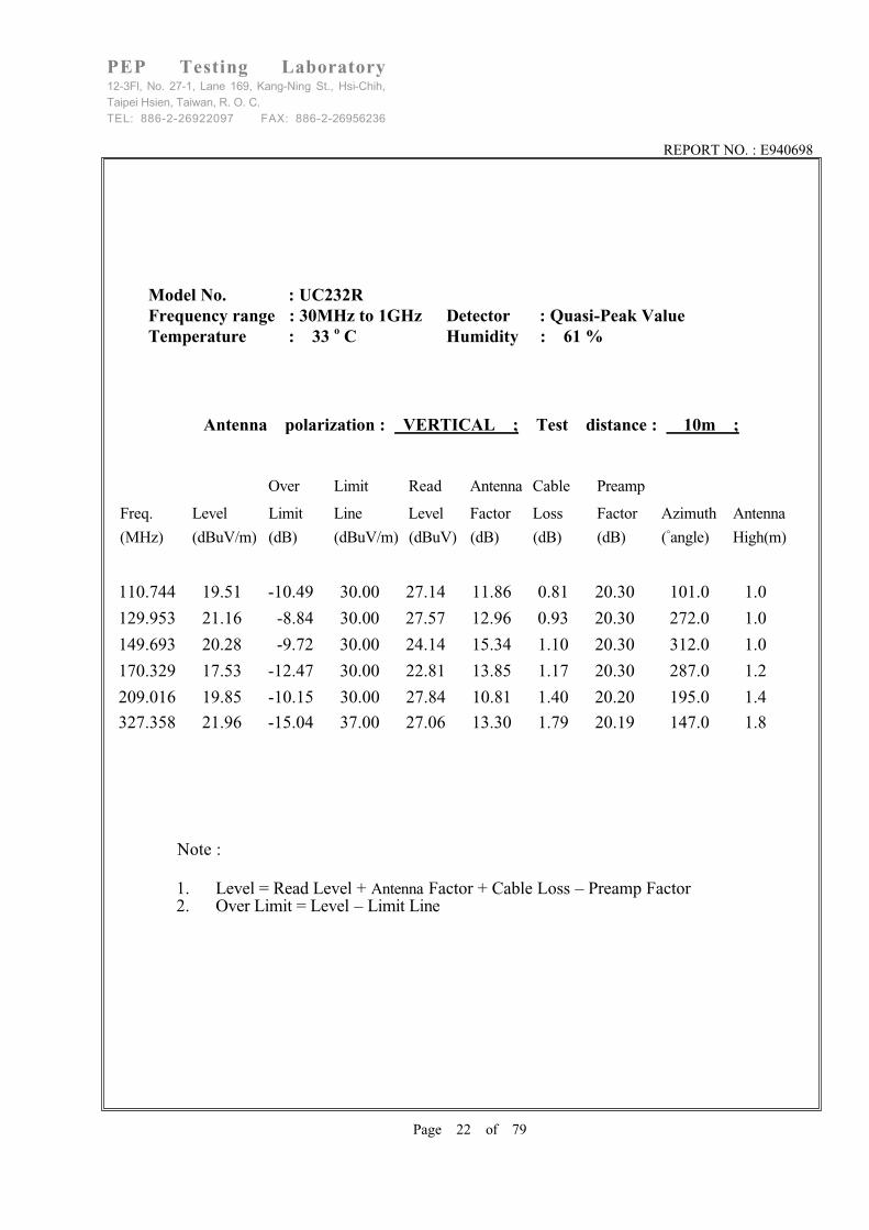
13.4 Fast Transient Burst Test Setup Photo
< FRONT VIEW >

REPORT NO. : E940698
Page 52 of 79
PEP Testing Laboratory12-3Fl, No. 27-1, Lane 169, Kang-Ning St., Hsi-Chih,Taipei Hsien, Taiwan, R. O. C.TEL: 886-2-26922097 FAX: 886-2-26956236
13.5 Fast Transient Burst Test Data
MODEL NO. : UC232R
REGULATION : According to EN 61000-4-4 ( 1995+A2: 2001 ) Spec .
TEST RESULT
Temperature : 28 degree . Duration of tests : 1 min .
Relative Humidity : 52 % RH . Time between test : 60 second .
Pulse : 5 / 50 ns . AC Power : 230 Vac .
Burst : 15 ms / 300 ms . DC Power : N/A Vdc .
0.5 KV 1 KV KVVoltage \ Polarity
\ Test Point \ Mode \ Result + - + - + -
L / / P P / /
N / / P P / /Power Line
G / / P P / /
Signal Line Clamp Test
/ / / / / /
Note : 1. “ P “ mean the EUT function is correct during the test .
2. “ F “ - - - - Fail
3. “ / ” - - - - no test

REPORT NO. : E940698
Page 53 of 79
PEP Testing Laboratory12-3Fl, No. 27-1, Lane 169, Kang-Ning St., Hsi-Chih,Taipei Hsien, Taiwan, R. O. C.TEL: 886-2-26922097 FAX: 886-2-26956236
14. EN 61000-4-5 Surge Immunity Test
Test Standard Model No. Result
EN 61000-4-5 UC232R B
The test results shall be classified on the basis of the operating conditions and the functional specifications of the equipment under test , as in the following , unless different specifications are given by product committees or product specifications : Performance Criterion : A) normal performance within the specification limits ; B) temporary degradation or loss of function or performance which is self-recoverable ; C) temporary degradation or loss of function or performance which requires operator intervention or system reset ;

REPORT NO. : E940698
Page 54 of 79
PEP Testing Laboratory12-3Fl, No. 27-1, Lane 169, Kang-Ning St., Hsi-Chih,Taipei Hsien, Taiwan, R. O. C.TEL: 886-2-26922097 FAX: 886-2-26956236
14.1 Surge Immunity Test Description
The task of the described laboratory test is to find the reaction of the EUT under specified
operational conditions caused by surge voltages from switching and lightning effects at certain
threat levels.
The following equipment is part of the test set-up :
- equipment under test (EUT);
- auxiliary equipment (AE);
- cables (of specified type and lengeh);
- coupling device (capacitive or arrestors);
- test generator (combination wave generator, 1.2/50 µs generator);
- decoupling network/protection devices;
- additional resistors, 10 ohm and 40 ohm
The surge is to be applied to the EUT MBS terminals via the capacitive coupling network.
Decoupling networks are required in order to avoid possible adverse effects on equipment not
under test that may be powered by the same lines and to provide sufficient decoupling impedance
to the surge wave so that the specified wave may be developed on the lines under test .

REPORT NO. : E940698
Page 55 of 79
PEP Testing Laboratory12-3Fl, No. 27-1, Lane 169, Kang-Ning St., Hsi-Chih,Taipei Hsien, Taiwan, R. O. C.TEL: 886-2-26922097 FAX: 886-2-26956236
14.2 Surge Immunity Test Setup
AC(DC)power supplynetwork
Example of test set- up for capacltive coupling on a.c./d.c. kines;line-to-earth coupling (according to 7.2)
Decoupling network
Combination wavegenerator
C=18µFL
N
PE
EUT
Earth reference
L
Example of test set- up for capacltive coupling on a.c./d.c. kines;line-to-line coupling (according to 7.2)
N
L
PE
EUT
Earth reference
AC(DC)power supplynetwork
Decoupling network
L
Combination wavegenerator
C = 9µFR = 10 ohm

REPORT NO. : E940698
Page 56 of 79
PEP Testing Laboratory12-3Fl, No. 27-1, Lane 169, Kang-Ning St., Hsi-Chih,Taipei Hsien, Taiwan, R. O. C.TEL: 886-2-26922097 FAX: 886-2-26956236
14.3 Surge Immunity Test Limits
The preferential range of test levels is given in table 1.
Table 1-Test levels
Open-circuit test voltage
Level +10 %-kV
1 0.52 1.03 2.04 4.0x Special
NOTE - x is an open class . The level can be specified in the product
specification .

REPORT NO. : E940698
Page 57 of 79
PEP Testing Laboratory12-3Fl, No. 27-1, Lane 169, Kang-Ning St., Hsi-Chih,Taipei Hsien, Taiwan, R. O. C.TEL: 886-2-26922097 FAX: 886-2-26956236
14.4 Surge Immunity Test Setup Photo
< FRONT VIEW >

REPORT NO. : E940698
Page 58 of 79
PEP Testing Laboratory12-3Fl, No. 27-1, Lane 169, Kang-Ning St., Hsi-Chih,Taipei Hsien, Taiwan, R. O. C.TEL: 886-2-26922097 FAX: 886-2-26956236
14.5 Surge Immunity Test Data
MODEL NO : UC232R
TEST SETUP : According to EN 61000-4-5 (1995+A1: 2001)
TEST RESULT
Temperature : 28 Relative Humidity 52 %RH
Waveform : 1,2 x 50 µs Test rate : 6 sec
Times 5 times / each condition AC power 230 VAC
\Phase
\Voltage\Mode\Polarity\Result
0 90 180 270
+ P P P P1KV
Line
Neutral - P P P P
+ / / / /2KV Line
Neutral - / / / /
+ P P P PLine
Ground - P P P P
+ P P P P
2KV
Neutral
Ground - P P P P
Note : 1. “ P ” means the EUT function is correct during the test
2. “ / ” no test

REPORT NO. : E940698
Page 59 of 79
PEP Testing Laboratory12-3Fl, No. 27-1, Lane 169, Kang-Ning St., Hsi-Chih,Taipei Hsien, Taiwan, R. O. C.TEL: 886-2-26922097 FAX: 886-2-26956236
15. EN 61000-4-6 Immunity To Conducted Disturbances, Induced By Radio-Frequency Fields
Test Standard Model No. Result
EN 61000-4-6 UC232R A
The test results shall be classified on the basis of the operating conditions and the functional specifications of the equipment under test , as in the following , unless different specifications are given by product committees or product specifications : Performance Criterion : A) normal performance within the specification limits ; B) temporary degradation or loss of function or performance which is self-recoverable ; C) temporary degradation or loss of function or performance which requires operator intervention or system reset ;

REPORT NO. : E940698
Page 60 of 79
PEP Testing Laboratory12-3Fl, No. 27-1, Lane 169, Kang-Ning St., Hsi-Chih,Taipei Hsien, Taiwan, R. O. C.TEL: 886-2-26922097 FAX: 886-2-26956236
15.1 Immunity To Conducted Disturbances, Induced By Radio-Frequency Fields Description
The EUT shall be placed on an insulating support, 0.1 m above the ground reference plane.
For table-top equipment, the ground reference plane may be placed on a table (see figure) .
On all cables to be tested, coupling and decoupling devices shall be inserted. The coupling
and decoupling devices shall be placed on the ground reference plane, making direct contact
with it at about 0.1 m to 0.3 m from the EUT. The cables between the coupling and
decoupling devices and the EUT shall be as short as possible and shall not be bundled nor
wrapped. height above the ground reference plane shall be between 30 mm and 50 mm.
If the EUT is provided with other earth terminals, they shall, when allowed, be connected to
the ground reference plane through the coupling and decoupling network CDN-M1, (i.e. the
AE port of the CDN-M1 is then connected to the ground reference).
If the EUT is provided with a keyboard or hand-held accessory, then the artificial hand shall
be placed on this keyboard or wrapped around the accessory and connected to the ground
reference plane.
Auxiliary equipment (AE) required for the defined operation of the EUT according to the
specifications of the product committee, e.g. communication equipment, modem, printer,
sensor, etc., as well as auxiliary equipment necessary for ensuring any data transfer and
assessment of the functions, shall be connected to the EUT through coupling and decoupling
devices. However, as far as possible the number of cables to be tested should be limited by
restricting attention to the representative functions.

REPORT NO. : E940698
Page 61 of 79
PEP Testing Laboratory12-3Fl, No. 27-1, Lane 169, Kang-Ning St., Hsi-Chih,Taipei Hsien, Taiwan, R. O. C.TEL: 886-2-26922097 FAX: 886-2-26956236
15.2 Immunity To Conducted Disturbances, Induced By Radio-Frequency Fields Setup
NOTE - The EUT clearance from any metallic obstacles shall be at least 0.5 m .All non-excited input ports of the CDNs shall be terminated by 50 ohm loads .
Example of test set-up with a single-unit systemfor class II safety equipment (see IEC 536)
Balanced pair
Mains
Unscreenednon-balancedcable
EUT
Insulating supporth = 0.1 m
Test generator
0.1 m < L <0.3m
To AE ortelecommunication lines
CDN-T2
T2
AECDN-AF2
T2
MainsCDN-M2
T2
0.5 m
0.5 m
Reference ground plane

REPORT NO. : E940698
Page 62 of 79
PEP Testing Laboratory12-3Fl, No. 27-1, Lane 169, Kang-Ning St., Hsi-Chih,Taipei Hsien, Taiwan, R. O. C.TEL: 886-2-26922097 FAX: 886-2-26956236
15.3 Immunity To Conducted Disturbances, Induced By Radio-Frequency Fields Test Limits
No tests are required for induced disturbances caused by electromagnetic fields coming from
intentional RF transmitters in the frequency range 9 kHz to 150 kHz,
The open-circuit test levels (e.m.f.) of the unmodulated disturbing signal, expressed in r.m.s.,
are given in table 1. The test levels are set at the EUT port of the coupling and decoupling
devices. For testing of equipment, this signal is 80% amplitude modulated with a 1 kHz sine
wave to simulate actual threats.
Table1 – Test levels
Frequency range 150 kHz – 80MHz
Level Voltage level (e.m.t.)Uo [dB( V)] Uo[V]
1
2
X1)
120 1
130 3
140 10
special1) X is an open level.

REPORT NO. : E940698
Page 63 of 79
PEP Testing Laboratory12-3Fl, No. 27-1, Lane 169, Kang-Ning St., Hsi-Chih,Taipei Hsien, Taiwan, R. O. C.TEL: 886-2-26922097 FAX: 886-2-26956236
15.4 Immunity To Conducted Disturbances, Induced By Radio-Frequency Fields Test Setup Photo
< FRONT VIEW >

REPORT NO. : E940698
Page 64 of 79
PEP Testing Laboratory12-3Fl, No. 27-1, Lane 169, Kang-Ning St., Hsi-Chih,Taipei Hsien, Taiwan, R. O. C.TEL: 886-2-26922097 FAX: 886-2-26956236
15.5 Immunity To Conducted Disturbances, Induced By Radio-Frequency Fields Test Data
MODEL NO. : UC232R
REGULATION : EN 61000-4-6 (1996+A1: 2001)
TEST RESULT
Temperature : 28 degree , Relative Humidity : 52 % RH
Start : 0.15 MHz , Stop : 80 MHz , Power : AC 230V
Modulation : AM 80 % , 1kHz. ON (YES ) , OFF ( )
Output impedance : 50 ohm , Source impedance : 150 ohm
Performance criterion : A
Test Ports Frequency(MHz)
Range
EUT Condition 1V(rms)
Field strength
3V(rms)
Field strength
Input / Output
a. c. power
0.15 - - - - - - 80 NORMAL / P
Input / Output
d. c.
0.15 - - - - - - 80 NORMAL / /
Signal lines
Control lines
0.15 - - - - - - 80 NORMAL / /
Note : 1. “ P ” mean the EUT function is correct during the test.
2. “ / ” no test.

REPORT NO. : E940698
Page 65 of 79
PEP Testing Laboratory12-3Fl, No. 27-1, Lane 169, Kang-Ning St., Hsi-Chih,Taipei Hsien, Taiwan, R. O. C.TEL: 886-2-26922097 FAX: 886-2-26956236
16. EN 61000-4-8 Power Frequency Magnetic Field Immunity Test
Test Standard Model No. Result
EN 61000-4-8 UC232R A
(A) Test instruments :HAEFELY&TRENCH magnetic field tester MAG100.1HAEFELY&TRENCH coil with clamp 1m x 1mHAEFELY&TRENCH support with castors height 2m
��
��
(C)
The test results shall be classified on the basis of the operating conditions and the functional specifications of the equipment under test , as in the following , unless different specifications are given by product committees or product specifications : Performance Criterion : A) normal performance within the specification limits ; B) temporary degradation or loss of function or performance which is self-recoverable ; C) temporary degradation or loss of function or performance which requires operator intervention or system reset ;

REPORT NO. : E940698
Page 66 of 79
PEP Testing Laboratory12-3Fl, No. 27-1, Lane 169, Kang-Ning St., Hsi-Chih,Taipei Hsien, Taiwan, R. O. C.TEL: 886-2-26922097 FAX: 886-2-26956236
16.1 Power Frequency Magnetic Field Immunity Test Description
The magnetic fields to which equipment is subjected may influence the reliable operation of equipment and systems.
The following tests are intended to demonstrate the immunity of equipment when subjected to power frequency magnetic fields related to the specific location and installation condition of the equipment (e.g. proximity of equipment to the disturbance source).The power frequency magnetic field is generated by power frequency current in conductors or, more seldom, from other devices (e.q. leakage of transformers) in the proximity ofequipment.
As for the influence of nearby conductors, one should differentiate between:- the current under normal operating conditions, which produces a steady magnetic field,with a comparatively small magnitude;- the current under fault conditions which can produce comparatively high magnetic fieldsbut of short duration, until the protection devices operate (a few milliseconds with fuses, a few seconds for protection relays).The test with a steady magnetic field may apply to all types of equipment intended forpublic or industrial low voltage distribution networks or for electrical plants.
The test with short duration magnetic field related to fault conditions, requires test levelsthat differ from those for steady state conditions; the highest values apply mainly toequipment to be installed in exposed places of electrical plants.
The test field waveform is that of power frequency.
In many cases (household areas, sub-stations and power plant under normal conditions), the magnetic field produced by harmonics is negligible. However, in very special cases likeheavy industrial areas (large power convectors, etc.) they occur, and will be considered in a future revision of this standard.
REPORT NO. : E940698
Page 67 of 79
PEP Testing Laboratory12-3Fl, No. 27-1, Lane 169, Kang-Ning St., Hsi-Chih,Taipei Hsien, Taiwan, R. O. C.TEL: 886-2-26922097 FAX: 886-2-26956236
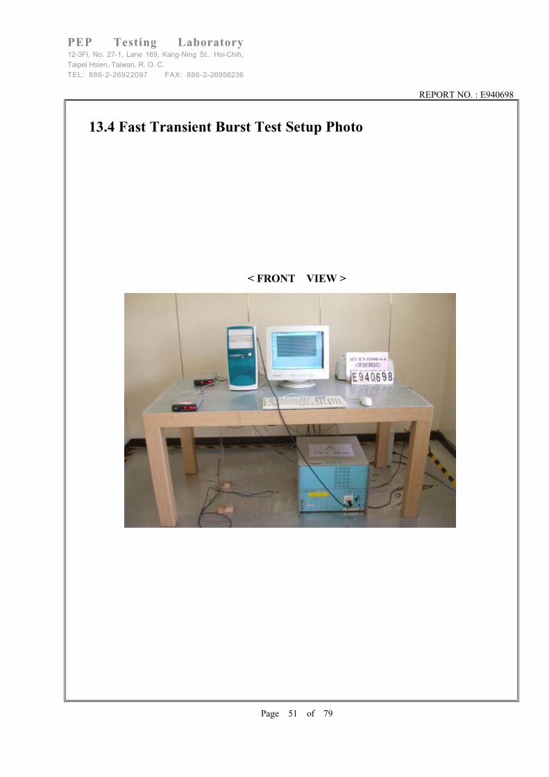
16.2 Power Frequency Magnetic Field Immunity Test Setup
Vertical magnetic field drawing
MAG100
AC powersource
EUT
AC powersource
MAG100
EUT

REPORT NO. : E940698
Page 68 of 79
PEP Testing Laboratory12-3Fl, No. 27-1, Lane 169, Kang-Ning St., Hsi-Chih,Taipei Hsien, Taiwan, R. O. C.TEL: 886-2-26922097 FAX: 886-2-26956236
16.3 Power Frequency Magnetic Field Immunity Test Limits
Table 1-Test levels for continuous field
Level Magnetic field strength
A/m
1 1
2 3
3 10
4 30
5 100
x1) special
NOTES
1 – “x” is an open level. This level can be given in the product specification.
Table 2 – Test levels for short duration: 1 s to 3 s
Level Magnetic field strength
A/m
1 n.a.2)
2 n.a.2)
3 n.a.2)
4 300
5 1000
x1) special
NOTES
1 – “x” is an open level. This level, as well the duration of the test, can be
given in the product specification.
2 – “n.a.” = not applicable

REPORT NO. : E940698
Page 69 of 79
PEP Testing Laboratory12-3Fl, No. 27-1, Lane 169, Kang-Ning St., Hsi-Chih,Taipei Hsien, Taiwan, R. O. C.TEL: 886-2-26922097 FAX: 886-2-26956236
16.4 Power Frequency Magnetic Field Immunity Test Setup Photos
< VERTICAL VIEW >
< HORIZONTAL VIEW >

REPORT NO. : E940698
Page 70 of 79
PEP Testing Laboratory12-3Fl, No. 27-1, Lane 169, Kang-Ning St., Hsi-Chih,Taipei Hsien, Taiwan, R. O. C.TEL: 886-2-26922097 FAX: 886-2-26956236
17. EN 61000-4-11 Voltage Dips, Short InterruptionsAnd Voltage Variations Immunity Tests
17.1 Voltage Dips,short Interruptions And Voltage VariationsImmunity Test Description
Electrical and electronic equipment may be affected by voltage dips, short interruptions or
voltage variations of Power Supply.
Voltage dips and short interruptions are caused by faults in the network, in installations or
by a sudden large change of load. In certain cases, two or more consecutive dips or
interruptions may occur. Voltage variations are caused by the continuously varying loads
connected to the network. Before starting the test of a given equipment, a test plan shall be
prepared.
It is recommended that the test plan shall comprise the following items :
- the type designation of the EUT;
- information on possible connections (plugs, terminals, etc.) and cables, and peripherals;
- input power port of equipment to be tested;
- representative operational modes of the EUT for the test;
- performance criteria used and defined in the technical specifications;
- operational mode(s) of equipment;
- description of the test set-up.
If the actual operating signal sources are not available to the EUT, they may be simulated.
For each test any degradation of performance shall be recorded.
The monitoring equipment should be capable of displaying the status of the operational
mode of the EUT during and after the tests. After each group of tests a full functional check
shall be performed.

REPORT NO. : E940698
Page 71 of 79
PEP Testing Laboratory12-3Fl, No. 27-1, Lane 169, Kang-Ning St., Hsi-Chih,Taipei Hsien, Taiwan, R. O. C.TEL: 886-2-26922097 FAX: 886-2-26956236
17.2 Voltage Dips, short Interruptions And Voltage VariationsImmunity Test Setup
EUTVoltmeter
oscilloscope
Variable transformer 1
Switch 1
Switch 2
Variable transformer 2
Phase
Neuteal
Powersupply
Schematic of test lnstrumentation for voltage dlps andshort interrupions using variable transformers and seitches
Poweramplifier
Wave-formgenerator
Controllwe
EUTVoltmeter
oscilloscope
Phase
Neutral
Powersupply
Schematic of test instrumentation for voltage dips,short interruptions and variations using power amplifier

REPORT NO. : E940698
Page 72 of 79
PEP Testing Laboratory12-3Fl, No. 27-1, Lane 169, Kang-Ning St., Hsi-Chih,Taipei Hsien, Taiwan, R. O. C.TEL: 886-2-26922097 FAX: 886-2-26956236
17.3 Voltage Dips, short Interruptions And Voltage VariationsImmunity Test Limits
Preferred test levels and durations for
voltage dips and short interruptions
Test level Voltage dip and Duration
short interruptions (in period)
%UT %UT
0.5*0 100 1
540 60 10
2570 30 50
x
* For 0.5 period, the test shall be made in positive and negative polarity,
i.e. starting at 0o and 180o, respectively .
NOTES
1 One or more of the above test levels and durations may be chosen .
2 If the EUT is tested for voltage dips of 100%, it is generally
unnecessary to test for other levels for the same durations. However, for
some cases (safeguard systems or electromechanical devices) it is not true.
The product specification or product committee shall give an indication
of the applicability of this note .
3 “x” is an open duration. This duration can be given in the product
specification. Utilities in Europe have measured dips and short interruptions
of duration between 1/2 a period and 3000 periods, but duration less than
50 periods are most common.
4 Any duration may apply to any test level .

REPORT NO. : E940698
Page 73 of 79
PEP Testing Laboratory12-3Fl, No. 27-1, Lane 169, Kang-Ning St., Hsi-Chih,Taipei Hsien, Taiwan, R. O. C.TEL: 886-2-26922097 FAX: 886-2-26956236
17.4 Voltage Dips, short Interruptions And Voltage Variations TestSetup Photo
< FRONT VIEW >

REPORT NO. : E940698
Page 74 of 79
PEP Testing Laboratory12-3Fl, No. 27-1, Lane 169, Kang-Ning St., Hsi-Chih,Taipei Hsien, Taiwan, R. O. C.TEL: 886-2-26922097 FAX: 886-2-26956236
17.5 Voltage Dips, short Interruptions And Voltage VariationsImmunity Test Data
MODEL NO. : UC232R
REGULAR : EN 61000-4-11 (1994+A1: 2001)
TEST RESULT : Test Voltage 230Vac
Test Level
%UT
Duration
( ms )
Performance
Criterion
>95 10 A Voltage dips
30 500 B
Voltage
interruptions
>95 5000 C
UT is the rated voltage for the equipment.

REPORT NO. : E940698
Page 75 of 79
PEP Testing Laboratory12-3Fl, No. 27-1, Lane 169, Kang-Ning St., Hsi-Chih,Taipei Hsien, Taiwan, R. O. C.TEL: 886-2-26922097 FAX: 886-2-26956236
18. Labelling Requirement, Warning
1. The vertical size is 5mm.2. The mark will be placed in a visible spot on the outside of the equipment, but in cases
where that is impractical, it may be included on the packaging and/or documentation.
ITE is subdivided into two categories denoted class A ITE and class B ITE.
Class A ITEClass A ITE is a category of all other ITE which satisfies the Class A ITE limits but not the Class B ITE limits. Such equipment should not be restricted in its sale but the following warning shall be included in the instructions for use :
WarningThis is a Class A product. In a domestic environment this product may cause radio interference in which case the user may be required to take adequate measures.
Class B ITEClass B ITE is a category of apparatus which satisfies the class B ITE disturbance limits.Class B ITE is intended primarily for use in the domestic environment and may include:- equipment with no fixed place of use; for example, portable equipment powered by built-in
batteries;- telecommunication terminal equipment powered by a telecommunication network;- personal computers and auxiliary connected equipment.

REPORT NO. : E940698
Page 76 of 79
PEP Testing Laboratory12-3Fl, No. 27-1, Lane 169, Kang-Ning St., Hsi-Chih,Taipei Hsien, Taiwan, R. O. C.TEL: 886-2-26922097 FAX: 886-2-26956236
19. The List of Test Instruments
Test Mode Instrument Model No. Serial No. Next Cal. Date Cal. Interval
AdvantestSpectrum R3261A 91720076 June 08, 2006 1Year
R & SLISN(EUT) ESH2-Z5 831886/004 Apr. 24, 2006 1Year
KyoritsuLISN(2nd) KNW-242 8-837-7 N/A N/A
Conduction
(No.2)
RF Cable No.4 N/A Feb. 18, 2006 1Year
R & SReceiver ESBI 845658/003 July 27, 2006 1Year
Schaffner
Pre-Amp.CPA-9232 1012 Aug. 20, 2006 1Year
SCHWARZBECKAntenna 9161 9161-4051 May 05, 2006 1Year
COM-Power
Horn Ant. AH-118
(1GHz~18GHz) 10095 May 20, 2006 1Year
RF Cable No.2 N/A Feb. 18, 2006 1Year
SCHWARZBECK
Precision Dipole
Ant.
VHAP
(30MHz~1GHz)
970+971
953+954June 27, 2006 3Year
Radiation
(OP No.3)
R & SSignal Generator SMY01 829846/038 Feb. 15, 2007 2Year

REPORT NO. : E940698
Page 77 of 79
PEP Testing Laboratory12-3Fl, No. 27-1, Lane 169, Kang-Ning St., Hsi-Chih,Taipei Hsien, Taiwan, R. O. C.TEL: 886-2-26922097 FAX: 886-2-26956236
Testitem
Instrument Model No. Serial No. Next Cal. Date Cal. Interval
(EMC-PARTNER)
Transient TesterTRA-2000/N6 456 Aug. 12, 2006 1Year
(EMC-PARTNER)ESD Test
SystemTRA1Z03B 399 Aug. 12, 2006 1Year
(EMC-PARTNER)EFT/B Clamp TAR1Z03B
CNEFT1000-268 Aug. 12, 2006 1Year
-4-2
-4-4-4-5-4-8
-4-11(EMC-PARTNER)
Magnetic Field
Loop antennaMF-1000
MF1000-169 Aug. 12, 2006 1Year
-4-6 CONDUCTEDIMMUNITY
CIT-10/102C3117
102C3117 July 24, 2006 2Years
-3-2
-3-3
(EMC-PARTNER)Harmonic/
FlickerHAR-1000 66 July 22, 2006 2Years
(Amplifier & Research)
Power Amplifier100W1000M11 25616 May 08, 2006 2Years
(Amplifier & Research)
Power MeterPM2002 N/A May 08, 2006 2Years
(Amplifier & Research)
Field MonitorFM5510 25355 May 08, 2006 2Years
(Amplifier & Research)
Field ProbeFP5000 25339 May 08, 2006 2Years
(Amplifier & Research)
Direct CouplerDC6080 N/A May 08, 2006 2Years
(Boonton)
Power Sensor51011-EMC 31094 May 08, 2006 2Years
EMS
(NO.2)
-4-3
(Boonton)
Power Sensor31011-EMC 31078 May 08, 2006 2Years

REPORT NO. : E940698
Page 78 of 79
PEP Testing Laboratory12-3Fl, No. 27-1, Lane 169, Kang-Ning St., Hsi-Chih,Taipei Hsien, Taiwan, R. O. C.TEL: 886-2-26922097 FAX: 886-2-26956236
20. EUT PhotosMODEL NO. : UC232R

REPORT NO. : E940698
Page 79 of 79
PEP Testing Laboratory12-3Fl, No. 27-1, Lane 169, Kang-Ning St., Hsi-Chih,Taipei Hsien, Taiwan, R. O. C.TEL: 886-2-26922097 FAX: 886-2-26956236

VERIFICATIONof conformity with
European EMC Directive
No. E940698
Document holder: FUTURE TECHNOLOGY DEVICES INTERNATIONAL LTD.
Type of equipment: Chipi
Type designation: UC232R
A sample of the equipment has been tested for CE-marking according to the EMC Directive, 89/336/EEC. &92/31/EEC & 93/68/EEC Standard(s) used for showing compliance with the essential requirements of thedirective:
EMC Standard(s):
EN 55022: 1998+A1: 2000+A2: 2003 Class BEN 61000-3-2: 2000EN 61000-3-3:1995+A1: 2001
Performance CriterionEN 55024: 1998+A1:2001+A2:2003
EN 61000-4-2: 1995+A1:1998+A2:2001 BEN 61000-4-3: 2002+ A1:2002 AEN 61000-4-4: 1995+A2: 2001 BEN 61000-4-5: 1995+A1: 2001 BEN 61000-4-6: 1996+A1: 2001 AEN 61000-4-8: 1993+A1: 2001 AEN 61000-4-11: 1994+A1: 2001
The referred test report(s) show that the product fulfills the requirements in the EMC Directive for CE marking. On this basis, together with the manufacturer’s own documented production control, the manufacturer (or his European authorized representative) can in his EC Declaration of Conformity verify compliance with the EMC Directive.
Signed for and on behalf of PEP Testing Laboratory
Date: SEP. 26, 2005 M. Y. Tsui / President

Declaration of ConformityThe following
Applicant : FUTURE TECHNOLOGY DEVICES INTERNATIONAL LTD.
Equipment : Chipi
Model No. : UC232R
Report No. : E940698
is herewith confirmed to comply with the requirements set out in the Council Directive on
the Approximation of the Laws of the Member States relating to Electromagnetic
Compatibility(89/336/EEC) and the amendments in the Council Directive 92/31/EEC,
93/68/EEC.
For the evaluation of above mentioned Directives, the following standards were applied:
1) EN 55022: 1998+A1 : 2000+A2 : 2003 Class B2) EN 61000-3-2 : 20003) EN 61000-3-3 : 1995+A1: 20014) EN 55024 : 1998+A1 : 2001+A2 : 2003
EN 61000-4-2 : 1995+A1: 1998 +A2: 2001EN 61000-4-3 : 2002+A1: 2002EN 61000-4-4 : 1995+A2: 2001EN 61000-4-5 : 1995+A1: 2001EN 61000-4-6 : 1996+A1: 2001EN 61000-4-8 : 1993+A1: 2001EN 61000-4-11 : 1994+A1: 2001
The following manufacturer is responsible for this declaration:
FUTURE TECHNOLOGY DEVICES INTERNATIONAL LTD.
373 SCOTLAND ST., GLASGOW G58QB SCOTLAND U. K.
U. K. / SEP. 26, 2005
Place and Date Signature of responsible Person