REPORT No. 860 - UNT Digital Library
13
REPORT No. 860 ANALYSIS OF COOLING ON LEVEL-FLIGHT LIMITATIONS AND EFFECT OF ENGINE-COOLING IMPROVEMENTS CRUISING PERFOR~MANCE OF FOUR-ENGINE HEAVY BOMBER By FRANK E. MARBLE, hfAHLON A. 311LLEE, and E. BAETON BELL SUMhIARY The N..C.4 haa dewdoped means, including an injection impeller and ducted head baj7e8, to improre the cooling charac- teristics of the $?360-cubic-inch-displacement radial en~”ne~ instulled in a four-engine heaoy bomber. T7ie improvements afforded proper cooling of the rear-row exhaust-m[ce seats for a wide range of cowl-jfup angles, mixture strengths, and air~lane 8peed8. The results of$ight teAe w“th thi8 airplane are u8ed as a baei.sfor a study to det+vmine the manner and the e.rtent to which the airplane performance was limited by engine cooling. By mea.n8 of thi8 analy~”8 for both the standard airplane and the airglane un”th en~”ne-cooling madijicution8, compam”80n of the specijic range at particular condition8 and comparison of tie crui8ing-performance limitations were made. The anal@8 of Lw./-jlight cruising performance of the air- pfane m“th both the 8tandard- and the ~d~~ed-en~”ne in8talfa- tion8 indicated that the mm-mum crut%ing economy is attained at the minimum brake 8pec@ fuel consumption when engine tooting under the8e condititm8 is po8et”b[e. @eration at lean zwi.xture8, high altitudes, and large gross weights ms limited for the standard airpfane by engt”ne cooling at the paint where larger cowl-jap openings increase the power regu.ired for lerel $ight at such a rate that the additional cooling air arwilable is insujicient to cool the engine when developing the additional ~u,er. When cooling becomes impossible at the minimum brake specijc juel conwmptwn, the maximum cruim”ng economy is obtained with a cowl-sap angle of approximately 6° and un”th the leanest mixture (abore the 8tut”ch. iometric value) gi~~ing8atis- fzctary engine cooling. Compam”80n of the calculated performance of the 8tandard and. the modiji.ed airplane indicated that cooling improvements increased the mm-mum 8peozj$c range as much aa 38 percent for operation where wide cowl#ap angles and enriched mixtures are required to cool the stano%rd airpfune. Corresponding increases in crwking range were calculated for $ights in which conditions allouing large increaseg in” cruising economy were encountered. I%e cooling improvements allow either an in- crease of more than 10,000 feet in operating altitude at a giren airplane uvight or a gros8-w&”ght increase of from 10,000 pounds al 8ea [erel to 86,000 pounds at all operating altitude8 above 10,000 feet. INTRODUCTION Economical cruising operation of the four-engine heavy bomber has been impaired by the rich mixtures and the large quantities of cooling air required to cool properly the 3350- cubic-iuch-displacement radial engines of this airpkme. The cooling dficulties caused by nonuniform mixture distri- bution and poor cooIing-air flow- over the critical regions of the rear-row cyIinders have resuItecl in frequent failure of the exhaust valve and the exhaust-valve seat. The dMicuIties experienced in cooling the exhaust-valve seats of the rear-row cylinders have been overcome to a con- siderable extent by improving the mixture distribution through application of the injection impeLler (reference 1) and by augmenting the flow of cooIing air to the critical temperature regions through installation of duct ed head baffles (reference 2). Flight tests of this airplane (reference 3) indicated that the temperatures of the exhaust-valve seats on rear-row cylinders were markedly lowered by these modi- fications and that airplane range, tdtitude, and gross vreight previously Iimited by these temperatures could be greatly increased. Under most normal flight conditions, reasonable operating temperature of the rear-row exhaust-valve se9 % were attained with the standard-engine installation for this airpIane only t.hrougli use of Iarge covrl-flap angles as well as enriched mixtures. The rear-row exhaust-valve seats of the modi.tied installation, ho-ivever, were properly cooled over wide rangw of cowl-flap angles and mixture strengths, thereby affording the possibility of improving the airplane perform- ance through proper adjustments in covd-flap and mMure- control setting. Although the maximum performance @_____ attained where both fuel ccmsumpt ion and cowl-flap angle are reduced to minimum values, it is usually necessary to increase one whan the other is decreased in order to avoid exceeding the limiting cylinder temperature. In order to use advantageously the improved airplane performance afforded by the engine modifications, the combination of cowl-flap angle and mixture strength that gives the optimum cruising performance with proper cooling must be determined. The possibility of extended airplane performance formerly pro- hibited by cooling di.tliculties must be investigated to evaluate fully the effectiveness of the cooling improwznent. Flight-test data of this four-engine heavy bomber obtained at the NACA CIeveland laboratory in 1944, me evaluated and analytically extended herein to show the effect of the injection impeller and ducted head baffles on the airplane performance. The relative effects of cowl-flap angle and specific fuel consumption on the specific range of the air- 415
Transcript of REPORT No. 860 - UNT Digital Library

REPORT No. 860
ANALYSIS OF COOLINGON LEVEL-FLIGHT
LIMITATIONS AND EFFECT OF ENGINE-COOLING IMPROVEMENTSCRUISING PERFOR~MANCE OF FOUR-ENGINE HEAVY BOMBER
By FRANK E. MARBLE, hfAHLON A. 311LLEE, and E. BAETON BELL
SUMhIARY
The N..C.4 haa dewdoped means, including an injectionimpeller and ducted head baj7e8, to improre the cooling charac-teristics of the $?360-cubic-inch-displacement radial en~”ne~instulled in a four-engine heaoy bomber. T7ie improvementsafforded proper cooling of the rear-row exhaust-m[ce seats for awide range of cowl-jfup angles, mixture strengths, and air~lane8peed8. The results of$ight teAe w“th thi8 airplane are u8ed asa baei.sfor a study to det+vmine the manner and the e.rtent to whichthe airplane performance was limited by engine cooling. Bymea.n8 of thi8 analy~”8 for both the standard airplane and theairglane un”th en~”ne-cooling madijicution8, compam”80n of thespecijic range at particular condition8 and comparison oftie crui8ing-performance limitations were made.
The anal@8 of Lw./-jlight cruising performance of the air-pfane m“th both the 8tandard- and the ~d~~ed-en~”ne in8talfa-tion8 indicated that the mm-mum crut%ing economy is attainedat the minimum brake 8pec@ fuel consumption when enginetooting under the8e condititm8 is po8et”b[e. @eration at leanzwi.xture8, high altitudes, and large gross weights ms limitedfor the standard airpfane by engt”ne cooling at the paint wherelarger cowl-jap openings increase the power regu.ired for lerel
$ight at such a rate that the additional cooling air arwilable isinsujicient to cool the engine when developing the additional~u,er. When cooling becomes impossible at the minimum brakespecijc juel conwmptwn, the maximum cruim”ng economy isobtained with a cowl-sap angle of approximately 6° and un”ththe leanest mixture (abore the 8tut”ch.iometric value) gi~~ing8atis-fzctary engine cooling.
Compam”80n of the calculated performance of the 8tandardand. the modiji.ed airplane indicated that cooling improvementsincreased the mm-mum 8peozj$c range as much aa 38 percentfor operation where wide cowl#ap angles and enriched mixturesare required to cool the stano%rd airpfune. Correspondingincreases in crwking range were calculated for $ights in whichconditions allouing large increaseg in” cruising economy wereencountered. I%e cooling improvements allow either an in-crease of more than 10,000 feet in operating altitude at a girenairplane uvight or a gros8-w&”ght increase of from 10,000pounds al 8ea [erel to 86,000 pounds at all operating altitude8above 10,000 feet.
INTRODUCTION
Economical cruising operation of the four-engine heavybomber has been impaired by the rich mixtures and the large
quantities of cooling air required to cool properly the 3350-cubic-iuch-displacement radial engines of this airpkme.The cooling dficulties caused by nonuniform mixture distri-bution and poor cooIing-air flow- over the critical regions ofthe rear-row cyIinders have resuItecl in frequent failure of theexhaust valve and the exhaust-valve seat.
The dMicuIties experienced in cooling the exhaust-valveseats of the rear-row cylinders have been overcome to a con-siderable extent by improving the mixture distributionthrough application of the injection impeLler (reference 1)and by augmenting the flow of cooIing air to the criticaltemperature regions through installation of duct ed headbaffles (reference 2). Flight tests of this airplane (reference3) indicated that the temperatures of the exhaust-valve seatson rear-row cylinders were markedly lowered by these modi-fications and that airplane range, tdtitude, and gross vreightpreviously Iimited by these temperatures could be greatlyincreased. Under most normal flight conditions, reasonableoperating temperature of the rear-row exhaust-valve se9 %were attained with the standard-engine installation for thisairpIane only t.hrougli use of Iarge covrl-flap angles as well asenriched mixtures. The rear-row exhaust-valve seats of themodi.tied installation, ho-ivever, were properly cooled overwide rangw of cowl-flap angles and mixture strengths, therebyaffording the possibility of improving the airplane perform-ance through proper adjustments in covd-flap and mMure-control setting. Although the maximum performance @_____attained where both fuel ccmsumpt ion and cowl-flap angleare reduced to minimum values, it is usually necessary toincrease one whan the other is decreased in order to avoidexceeding the limiting cylinder temperature. In order to useadvantageously the improved airplane performance affordedby the engine modifications, the combination of cowl-flapangle and mixture strength that gives the optimum cruisingperformance with proper cooling must be determined. Thepossibility of extended airplane performance formerly pro-hibited by cooling di.tliculties must be investigated to evaluatefully the effectiveness of the cooling improwznent.
Flight-test data of this four-engine heavy bomber obtainedat the NACA CIeveland laboratory in 1944, me evaluatedand analytically extended herein to show the effect of theinjection impeller and ducted head baffles on the airplaneperformance. The relative effects of cowl-flap angle andspecific fuel consumption on the specific range of the air-
415

416 REPORT NO. 886 .—~NATIONA~” ADVISORY COMMITTEE FOR AEROh’AUTICS
plane with standard and modiiied engines are determinedas well as the combinations affording the maximum specificrange. With the maximum specific range used as a mite-rion, the effects of the engine-cooling improvements on thespecific range and the cooling limits of operation are com-putid. The calculations cover cruising conditions at alti-tudes from sea level to 35,OOO feet and airplane weightsfrom 75,000 to 150,000 pounds.
SYMBOLS ‘-
The foIIowing symbols are used in this report:
Ac.~D,PCL
cp(r#))
c
EillPAp
!l
R8
T.T.T~17
w’
:r
a(f$)
PPo
~P+v4
The
effective aspect ratioover-all drag coefficientbasic parasite-drag coefficientlift coefficient
Apcooling-air pressuredrop coeficiegt, ~
~Pv~
brake specific fuel consumption, pounds per brakehorsepower-hour
speciiic range, miles per pound of fuelcombustion-air mass flow, pounds per secondpower per engine, brake horsepowercooling-air pressure drop, inches of water
free-stream dynamic pressure, ~PVs, pounds per
square footairplane Ievel-flight cruising range, milesdistance, milescooling-air temperature ahead of engine, ‘Feflective combustion-gas temperature, ‘FcyIinder-head temperature, “1?true airspeed, miles per hourairplane gross weight, poundsgross weight of airpIane without fuel, poundsweight of fuel, poundsincremental drag coefficient resulting from cowl-flap
angleair density, slugs per cubic foot.air density (standard sea-level Army summer air,
0.00221), slugs per cubic footratio of free-air density to standard-air density, p/Po
apparent brake horsepower
indicated airspeed, miles per hourcowl-flap angle, degrees
subscript o represents sea-Ievel refaence conditions.
ANALYSIS
The improvement in airpIane cruising performance effectedby cooling improvements maybe demonstrated by comparingcruising range and cooling-limited performance of standard-and modiiied-engine installations. This comparison requiresthat the conditions for best cruising economy, as well as thetrue nature of the limitations, be analyzed. In order LOundertake this analysis with sticient accuracy and for awide variety of airplane operating conditions, it is necessary
to investigate the relations among the airplane pmforrnancc,the engine performance, the engine cooling characteristics,and the associated variables.
AIRPLANECRUISINGRANGE
The specific range of an airplane, thtit is, the dietuncc thatmay be flown for each pound of fuel e.xpendcd at a givenaltitude, speed, and gross weight, may be cxprcsscd nnalytic-ally by
E–––ii%
(1)
where the minus sign indicates that th c fuel weightdecreases. during flight. Consequently, the range of theairplane may be written as
(2)
where the integration covers weight-s from full to emptyfuel supply. The variable of integration and the appro-priate limits may refer to either the fuel weight or thegross airplane weight because the variations of onc amthe same” as those of the other if oil consumption andabrupt changes of gross weight, such as disposal ofbombs, are neglected. The gross rtirplane wcighL is moroconvenient than the fuel weight inasmuch as it directlyinfluences the specific range.
The most accurate evaluation of equation (2) rcquireanumerical methods because tho cluantitics aff~cting t.hointegrand. -vary with gross airplane weight in ways that arodifficult to e--press analytically. Because of theso inter-relations, the specific range, and consequently the airplanocruising range, are functions of several variables not all ofwhich are independent. Both the gross weight of the tiir-plane and the cruising altitude are usually fixed by conditionsother than specific range. The opt imum cruising conditionsfor any particular airplane weight and cruising a~tiLudc aretherefore the vahws of the remaining variables thaL givethe integial in equation (2) a maximum value and at thesame time provide proper cooling.
SPECIPICRANGE
Method of solutiori.-In order to calculate the spccifiorange of the four-engine heavy bomber, it was necessmyto have ii either analytical or graphical form the aerody-namic characteristics of the. airplane, the cngin e opmatingperformance, and the engine cooling requiremem%. Thcaevariables. are not independent but are related through therequirements that the engine be properly cooled and thatthe airplane be maintained in level flight.
For a given altitude and gross airplane weighL, the physicalrelations among the variables that define the specific rangeare:
I. Power required by the airplane for steady levelflight-determined by the airplane speed and thecowl-flap opening

EFFECT OF ENGINE-COOLING IMPROVEMENTS ON CRUISING PERFORMANCE OF HEAVY BOMBER 417
2. Cooling-air pressure drop required to cool the engineto the limiting head temperature-determined bythe engine power output and the brake specific fuelconsumption
3. Cooling-air pressure drop available across the engine(necessarily equal to the pressure drop requiredwhen operating at the limiting head temperature)—determined by the airplane speed and the cowl-llap opening
Together with the definition of specific range, these relationsform a set of four simultaneous aIgebraic equations in sixvariables. Four of these variables can therefore be elimi-nated and the cruising economy expressed in terms of any two.The airpkme speed and the brake specific fuel consumptionaro considered the independent variables and the maximumvahs of specific range with respect to these variabka aredetermined by graphimd means.
Assumptions for calculations,-The analysis was based onstandard Army summer air conditions and on the conserva-tive temperature limit of 560° F at the exihaus+valve seat(corresponding to a Iimit between 420° and 440° F at the rearspark-plug gasket of the standard engine) of the hottest rear-row cylinder. It was assumed that limiting exhaust-valve-seat temperatures would not be encountered on the front-rowcylinders where the critical regions are more adequatelycooled. The relation between the engine speed and the en-gine power was taken to be a propelhdoad curve (fig. I)detined by the rated engine conditions. The resulting indi-cated mean efTective pressures were below the knock limitfor all fuel-air ratios. For operation along the propeller-loadcurve, the relation between brake speci6c fuel consumptionand fuel-air ratio (@. 2) was approximated from flight-testrasults and from estimates of the engine manufacturer. Theanalytical performance comparison for the airplane withstandard- and modified-engine installations should bematerially untiected by the approximate nature of this re-lation because brake horsepowers above the normal rated2000 for the engine were not used in the calculations.
RELATIONSAMONGFUNDAMENTALVABIABLES
The formulation of the relations affecting the airpkmecruising economy nec-itates analysis of these flight tw+ts.Each of the three fundamental relations will be consideredseparately.
Brake horsepower requfred.-An an alyticaI approximationof the brake horsepower required for leveI fight may befound when the relation between the lift and the drag coefE-cients of the airplane m-eknown. If the airplane is consideredan elliptically loaded wing of finite span (reference 4), thedrag coefficient may be expressed as the sum of the parasitetind the induced drag coefficients
CD= CD,P[(l+@]+~ (3)
where the incremental drag coefficient a(d) accounts for theaddit.ionaI drag re.suhg from the cooling-air momentum loss
FImmE I.–Relation betweeuenginepower and enghe speed mrm.spondlngto pfopella=Imd curre W on ratedengfnemndftfma,
and the true parasite drag of the cowl flaps. The coefficientwas based on a wing area of 175o square feet. lVTumericalvalues of the parasite drag coefficient with closed COWIflapsC~,9,0and the effective aspect ratio of the equivalent ellipti-cally loaded wing A, as well as the relation between theincremental drag coef%cient and the covd-flap anglel cgn bedetermined.
In order to obtain values of the unknown quantities ofequation (3), a limited number of ilight tests with the air-plane -were undertaken in which airspeed, altitude, and otherpertinent fight data were accurately measured. The brakehorsepower was determined on two of the four radial enginesof 3350-cubic-inch displacement from torquemeter reaclingaand was estimated for the other two engines from carefullyobserved engine operating conditions. The weight of theairplane was approximated from the known weight of theempty airplane and the approximated weights of equipment,personnel, and fuel at the particular time of test.
The method of relating the power requirements to thelift and drag coefficients is well known and its application tothe generalization of flight-test data is thoroughly discussedin references 5 and 6. The hear relation between theover-all drag coefficient (closed cowl flaps) and the squareof the lift coefficient was determined from flight teats at
:- 1 I I I,2 .60 Engine speed.m I (rPm)g- 2403
72nn
I I I I I t [ I I I I J= J’/ .
‘6 .060 .064 .068 .072 .076 .060 .064 .~8 .0.S2?Fue/-air FO tio
FmuM S.-Appmx&mta verfotlonof brakeepeefdcfud consumptionwith owr-all fnekdrratiofor verfmuengfnespwk
418 REPORT NO. t360.-NATIONAJ.J ADVTSORY COMMWJ7EE FOR AERONAU’IWS
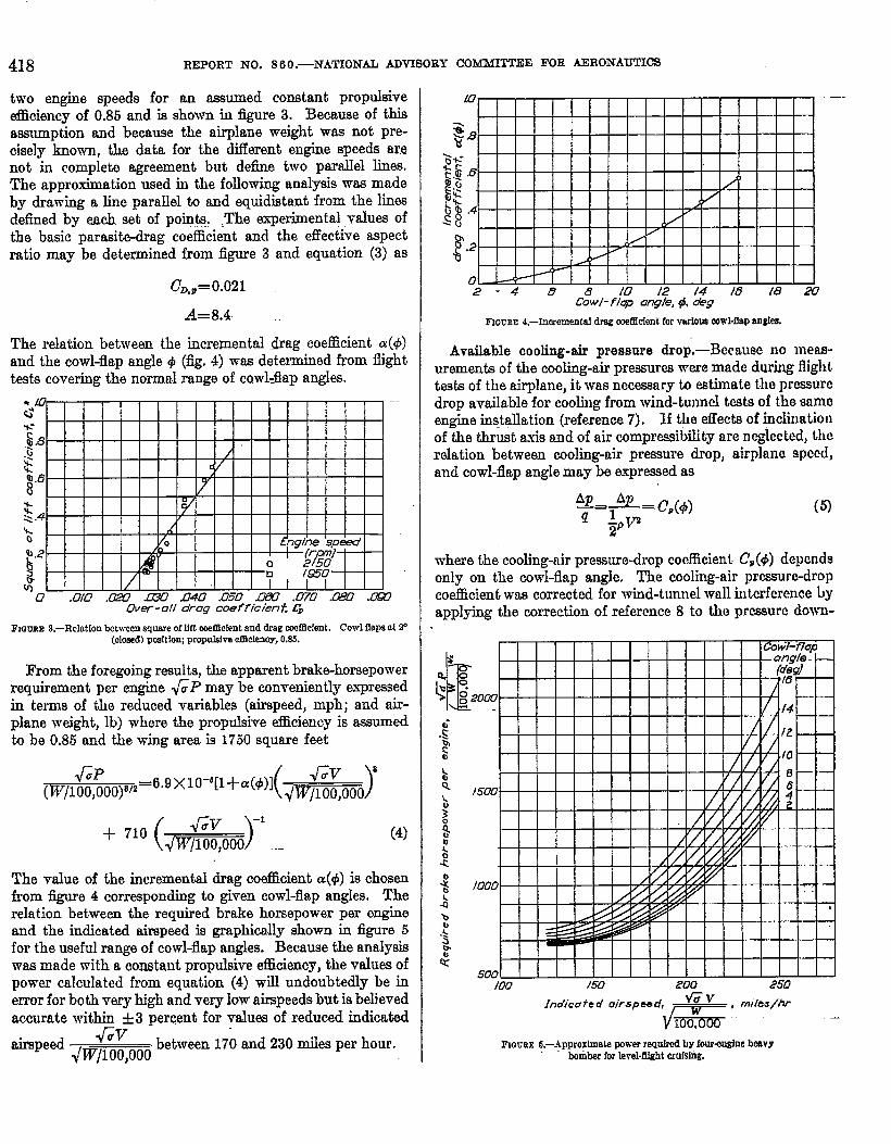
two engine speeds for art assumed constant propulsiveefficiency of 0.85 and is shown i-u ilgure 3. Because of thiEassumption and because the airplane weight wns not pre-cisely known, the data for the ditIerent engine speeds arenot in completa agreement but defie two parallel lines.The approximation used in the following analysis w= madeby drawing a line parallel to and equidistant from the linesdefied by each set of points. ... The experimental values ofthe basic parasitedrag coefficient and the effective aspectratio may be determined from figure 3 and equation (3) as
CD,,= O.021
A=8.4-
The relation between the incremental drag coefficient CS(4)and the cowl-flap angle @(fig. 4) -was determined from flighttests covering the normfd range of cowl-flap ang1e5.
—Over- all drag coefficient CD
FmrJRE9,–Relation betweenwwre of lift welllc!entend dragwdticlent. Cowl flapsot P(closed)positiorupropulsiveemcienoy,0.85.
From the foregoing results, the apparent brake-horsepowerrequirement per engine &P may be conveniently expressedin terms of the reduced variables (airspeed, mph; and airp-lane weight, lb) where the propulsive efficiency is assumedto be 0.85 and the wing area is 1750 square feet
6P @ 8(w/l oo,ooo)’/’
=6.9 X10⁻⁵ [l+a(&~0)
(
JW)-1
+ 710 ~ --(4)
The vilue of the incremental drag coefficient a(~) is chosenfrom fi~e 4 corresponding to given cowl-flap angles. Therelation between the required brake horsepower per engineand the indicated airspeed is graphically shown in figure 5for the useful range of cowl-flap angles. Because the analysiswas made with a constant propukve efficiency, the values ofpower calculated from equation (4) will undoubtedly be inerror for both very high and very low airspeeds but is believedaccurate within &3 percent for values of reduced indicated
r..airspeed
quvbetween 170 and 230 miles per hour.Jwfloo,ooi)
Fnmnm4.—Inwmental dn?g.meRfeientfor varfouacowl-flapangks.
Available cooling-air pressure drop,-Because no nleas-urements of the cooling-air prewmrcs were made during frighttests of the airplane, it was necessary to estimate tho pressuredrop available for cooling from wind-tunnel tests of the srtmoengine in9tgllation (reference 7). lf the effect43of inclinationof the thrust wris and of air compressibility are neglected, therelation between cooling-air pressure drop, airpkum speed,and cowl-flap angle may be exprwsed as
Ap Ap—= —=c,(r#J)~ Avz
2P
(5}
where the cooling-nir pressure-drop coefficient. C’P(4) dependsonly on the cow+flap angle. The cooling-air prumrc-dropcoefhcient was corrected for wind-tunnel wall interference byapplying the correction of reference 8 to the pressure down-
/00 /50 200 250
Indicate d oirspee d, Gv
G ‘“”’’7’” “’FmcrtE 5.—ApproxhnaLaIWVerrequiredby four+nglneheavY.
bomberfor Ievel-tlkhtcrufslng.
EFFECT OF ENGINE-COOLING IMPROVEMENTS ON CRUISING PERFORMANCE OF HEAVY BOMBER 419
Cowl- flap angle, e, deg
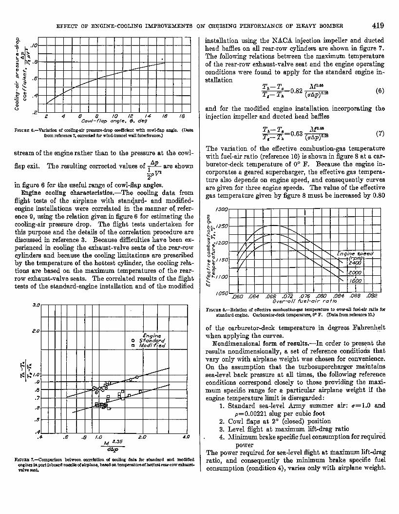
FIGURE6.—VruMon of coolfng-rdrpt~ eMMent wtth cowl-tip 8ngIe. (Dowfromreference7, correetedfor wLnd-trmnelw811Merferenrm]
stream of the engine rather than to the pressure at the cowl-
fktp exit. The resulting corrected VSIUSS of ~ are shown$~q
in figure 6 for the useful range of cowI-flap angles.Engine cooling characteristics,-The cooling data from
flight tests of the airplane with stan@rd- and modified-engine instdkdions were correlated in the manner of refer-ence 9, using the relation given in @ure 6 for estimating thecooling-air pressure drop. The flight tests undertaken forthis purpose and the details of the correlation procedure arediscussed in reference 3. Because difEcult.ies have been ex-perienced in cooling the exhaust-valve seats of the rear-rowcyIindere and because the cooling limitations are prescribedby the temperature of the hottest cylinder, the cooling rela-tions are based on the maximum temperatures of the rear-row exhaust-valve seats. The correlated remdts of the flighttests of the standard-engine installation and of the modilled
3.0
2.0
$ ~
K ;. I“o.s.e.7
.8
.s
.4.4 .6 .8 /.0 2.0 4.0
~ 2.35
aA~
EIGuzfr7.-Compnrkon between mmelatfond molbg data for standard aud modfSedeU&e9*9LP3r’tfnw-offiPb% - Ontempemtnroofhottestrear-rowexharr9t-
installation using the N’ACA injection impeIler and ductedhead bfles on all rear-row- cylindem are ahown in figure 7.The foIlowing relations between the maximum temperatureof the rear-row exhaust-valve seat and the engine operatingconditions were found to apply for the standard engine in-stallation
T,– T. Mom
T.– Th=O-82 (uAp)O.m(6)
and for the modified engine inst allat ion incorporating theinjection impeller and ducted head baflles
T,– T. *Jpee
T.– T,=0.03 (uAp)O.a(7)
The variation of the effective combustion-gas temperaturewith fuel-air rat io (reference 10) is shown in figure 8 at a car-buretordeck temperature of 0° F. Because the engine iri-corporates a. geared supercharger, the effective gas tempera-ture also depends on engine speed, and consequently curvesare given for three engine speeds. The vrdue of the effectivegas temperature given by figure 8 must be increased by 0.80
I 050 1 I t 1 1 I I I~60 .064 .068 .072 .076 .080 .084 .088 .=
Overwll fuel-air ra f to .-Fmcrm S.–Relation of eflective cornhust!ommstemperatureto orerd frrekfr ratfo fw
standardengfrre. Carbnretordecktemperature,W F. (Data fromreferenee10.)
of the carburetordeck temperature in degre= Fahrenheitwhen applying the curves.
Nondimensional form of results,-In order to present theresults nondimenaionally, a set of reference conditioti thatvary only -with airplane weight was chosen for convenience.On the assumption that the tnrbosupercharger maintainssea-level back pressure at ill times, the following referenceconditions correspond closely to those providing the maxi-mum specific range for a particular airplane weight if theengine temperature limit is disregarded:
1. Standard sea-level Army summer air: a= 1.0 and~= 0.00221 alug per cubic foot
2. Cowl flaps at 2° (closed) position3. Level flight at maximum lift-drag ratio4. Jiinimum brake specfic fuel consumption for required
powerThe power required for sea-level fight at rn~timum lift-dragratio, and consequently the minimum brake specific fuelconsumption (condition 4), varies only with airplane weight.

420 REPORT NO. 860.—NATIONAL ADVISORY COMMI’Fl’EE FOR AERONAUTICS
FIO!XE W-Level-dfgIrtwufsfrrgcandkionsforvwiouegmwrdrplaneweight.%StandardsewlevelArmy eummerafr(.-1.0 andp-0.00M slug pcr cubiofoot); WWIalarmat 2° (ckmed)poeftior,levelflightat maxlrnnnrltft-dragratio;rrdnfmmnbrakes~ottlcfnel coneumptlonforreqnkedpower.
The values of the airplane specific range and the valuee ofthe important associated variables are shown in figure 9 forthe reference conditions over the complete range of airplaneweights.
RESULTS AND DISCUSS1ON
In the presentation of the relation between the specificrange and the airplane operating conditions as well as in thecomparison of the airplane using the standard- and the modi-fied-engine installations, the specif% range has been expressedas a function of the brake specfic fuel ccmsumpt.ion and oneof the three flight variables: airspeed, altitude, or grossairplane weight. These relations among the variables af-fecting the specfic range of the airplane are represented by”three-dimensional curves.
PERFORMANCELIMITATIONSIMPOSEDBY COOLfNGREQUIEEMENTSAND ENGINEOPERATION
The natyre of the performance Iimitdiona imposed by the
engine performance and the cooling requirements may ho
understood through graphicnl solution (fig. 10) of tho si-multaneous equations characterizing cruising with propc
engine coding. For operation at a given altitude, airplnnc
gross weight, and cowl-flap angle, the apparent power re-
quired is related to the indicated airspeed by equation (4)
and the specific range may be found in terms of the indicatwl
airspeed and the brake specific fuel consumption. Thisrelation, plotted three-dimensionally in figure 10 (a}, isterminated by the minimum attainable brake specific fuelconsumption, as indicated by the hatchwi area. Inasmuchas the engine power is known, the engine speed, the fuel-nir. .—ratio, and the cooling-air pressure drop (figs. 1, 2, and 6,respectively) can be found for a given indicated airspeed Rndbrake specific fuel consumption. This information is suffi-cient for calculating the temperature of the. exhaust-valveseat according to equation (6) or equation (7) and conse-quently any point of the surface representing specific rrmgoat a given cow-l-flap angle (fig. 10 (a)) has a definite cylindcr-head temperature. Curves of constant hctid tempwwturccan then be drawn on the surface, as shown in figure 10 (b).The m~~timnm cylinder-temperature criterion prohibited safuengine operation. in a certain area of the specific-range surfacowith the restrictl.on most severe in the vicinity of tho stoichio-metric mixture where the maximum combustion-gas tempera-ture occurs. The hatched area of figure 10 (b) must t.hcrcforcbe disregarded because of cooling difficulties. A similarsituation exists for each cowl-flap opening; tlwsc othersurfaces and their limiting temperatures lines arc shown in&we 10 (c). The usable envelope of these surfaces (fig.10 (d)) encompasses, for the assumcc] aIt itude and grossairplane weight, all crutilng conditions possible with properengine cooIing. The surface representing the Iimiting specific.range consists of three distinct parts: (1) normal specific-range surfa~wit,h closed cowl flaps, continuing until limitinghead temperature is reached; (2) the portion for which lin]it.-ing head temperature exists for all cowl-flap angIcs; and (3)the normal cruising economy surface at full-open cowl flaps,continuing untiI limiting heacl temperatures arc reached.Although excessive cooling is available at R1l points withinthis region, the most economical cruising conditions arcrepresented by the upper portion of the surface and conse-quently only this part need be considered.
The operating altitude or the gross weight, as well as theairspeed, could be considered individually indepcmdrnt andsimilar surfaces would be obtained. Surfaces of this typoare shown in figures 11 to 13 for the standard-engine installa-tion. The extension of operation toward high speeds, ahi-tudes, or gross weights will be eventwdly limited by cmgino
power, whereas the limitation at rich mixtures (largo brako

(a]
EFFE~ OF ENf31NE-COOIJNG IMPROVEMENTS ON CRUISING J?=FOR~~N~ OF HEA= BOMB~ 421.
A OKIerm’ion o+whibited b v-r
“excessive head temp er;tu~e
2(i Cowl-flap on?fe required
8.$
4
fo obtain limiting headL imi f e d head fern ra *urea
Ftemperature .7
for kt?rioue’ cowl- lap [email protected] ,.4, pg: / .-%\ ..-,,4A-,>. b-
~
. - ---- Surface on Micb limifing‘. ....-.-.::..:.-::.\ ,.. . . head ~enpera ture--- --..:.=: \;..+.-: \ is attained.... .
2‘\
\\\
‘\\ \\
.
. .. ., Fbps are full a~en -I+w /1 ,.,~ \ 1/
r u.. ”
/ etiine is overcabfed
(e, ““w‘%
(a) Specbbranse mrfocefff constantcowl-flap@e. (b) SpeebWrmUemrfnm for mnstant cowl-flap @e showing curves d constant heed(o) speelae-nulgESurfacesfor vdm Colvl-ffapangles. temperature.
(d) Completespeclflc-ransesnrfwa.
FI~EBE10.—Developmentof smfaces showtusspeclf!omngewith properenginecoolfnsas fnnctfonof Jlfghtandensfnemrfnbk.
specific fuel consumption) is very indefinite. Operation atvery low speeds is aerod~amicall~ unstable. Becausethese Limitations are indefinite and of littIe importance herein,the figures are terminated arbitrarily at low speeds and richmixtures.
For a given brake specific fuel consumption, the airspeed(fig. 11), the altitude (fig. 12), and the gross weight (fig. 13)are limited by the availab~e cooling facilities. Coolinglimitations of airplane performance are most severe nearthe stoichiometric mixture; that is, where the maximum
value of the combustion-gas tempemture h ~co~tered.Satisfactory engine cooling can usually be attained at en-riched mi..tures but can or cannot be attained at rnkturesleaner than the stoichiometric, depending on the severityof the cooling requirements and on the mixture at whichengine operation becomes unsatisfactory.
V7hen a cooling knit exists, it can be physically observedby noting the response of specfic range to the progressiveIeaning of a rich mixture at a giv~ airplane speed. ~?n_the fuel-air ratio (or brake specific fuel ccmmmption) is de-

<
REPORT NO. 860.—NATIONAL ADV
FJGUREIl.—Effect of fJrapeWrmdbralres~iflcfu deom~ptlonms ~Ucmngewithcowl flapseatfor proper enginecooling. Wmdard-engfneinstallation;afrplaneweight,lCHI,CHMpounde;altitude,tOWfed.
creased, the cowl flaps must be opened to retain proper enginecooling. At some particular cowl-flap setting, dependingon the indicated airspeed, a greater cowl-ff ap angle necessi-tates such a large increase in engine power that the cooling-air pressure drops required are greater than those availablefrom the increased cowl-flap angle. An example of t]liscooling limit occum in figure 11 at an indicated-airspeedratio of 1.30. Continuous leaning of the mixture is there-fore impossible and the additional cowl-flap opening hasonly decreased the specific range at the same mixture andairpIane speed. Although successful airplane operationand engine cooling can be accomplished at cowl-flap anglesgreater than those occurring at the cooling-limited perform-ance, increased fuel consumption and sacrifice in specificrange results. Such conditions of operation are of nopractical importance.
DIHERMINATION OF MAXIMUMSPECIFICRANGE
For a given airplane weight and operating altitude, it
‘ISORY C03.iKfI~EEFOR AERONAUTICS
appeara from figure 11 that proper engine cooling may beattained at a variety of airspeeds, mixtures, and cowl-flapangles. The combination of these variables affording [homost desirable cruising performance must l.)c used ns tt guideto the proper flying conditions and to serve as a lmsis ofcomparison for the standard- and the mod ifi(~d<ngine
installations. The masimum spcc.ific rnngo wrts consideredthe governing factor for level-flight conditions; however, inorder to investigate the esscntiol characteristics of thospecific range at various airspeeds, determination of thomaximum specific range is considered in two parLs: (1)proper combination of cowl-flap angle nnd mixture strcng[.hjand (2) most economical airplnne speed.
Optimum combination of cowl-flap angle and mixturestrength,-The results of the analysis relating spccflc rfingoand cooling requirements fall into two chsscs, diflwwnt iatedby whether coohng is possible at mixtures leaner thtin thestoichionwtric. The distinction is not concerned, however,with cooling at the stoichiometric mixture.
FIccm lZ.—lMeetof afrpleneeltitudeand brakeepedflcfuelconeumpikmonaiw?~flcrengewith cowl Sapa wt for proper errgfneooolfng. Stnnderd-engtneInetnllfdfon;Indkfhl.afmeed ratio, LW ahdane wefght,lCO,WOpounds.

EFFECT OF ENGINE-COOLING IMPROVEMENTS ON CRUISING PERFORMANCE OF HEAVY BOM3ER 423
Typical examples of the first case, where cooIing is possibleat mixtures leaner than the stoichiometric, are shown infigure 11 by the cross sections at indicatecl-airsped ratios
I” ~“ of 100 and 115. IJnder these conditions, the greatest~ul= .
specific range for a given airspeed is alvrays attainable at theminimum brake spectic fuel consumption e-ren though ap-preciable co-d-flap angles are required; the cowl-flap anglegenerally appears to be of 1sss importance than the mixturestrength. This result does not preclude the possibility ofcooling improvements (such as changes in baffle conilgura-tion) that increase the specific range by decreasing therequired cowl-fIap angle for a given brake specific fueIconsumption.
The second case in figure 11, section at. ~~~= 1.30,
concerns the optimum cruisiig conditions when proper enginecooling is impossible near, or leaner than, the stoichiometricmixture. Rich inixtures are ~entially inefficient and canusually be avoided by reducing the airplane speed or altitude.When it is necessary to operate under circumstances requiringa rich mixture, both fuel-air ratio and cowI-flap angle must-be considered because reducing the fuel-air ratio to the mini-mum -raIue for which cooling is possible requires large cowl-flap w@= and effects considerable loss in specfic range.Although the maximum specific range occurs at widelycLitTerent mixture strengths depending on the airplane speed,altitude, and weight, the cowl-flap angIe for maximum specticrange for rich-mixture operation is usually between 4° ancl6°. Inasmuch as the specific range is insensitive to smallchang?s in mixture strength in the’ neighborhood of themaximum value, setting the cow] flap at approximately 5°and leaning the mixture until the limiting head temperatureis encountered appears to be a reasonable procedure forapproximating the maximum specific range.
Indicated airspeed,-The airspeed leading to the ma.xirnumspecific range for a. given altitude and airplane weight will beinvestigated in two cases depending, like the optimum com-bination of cowl flap and mixture, on whether engine coolingis possible at mixtures leaner than stoichiometric.
If proper cooling is attained at mixtures leaner thanstoichiometric, the maximum specific range is alvrays (for agiven airplane weight and aItitude) achieved at the airplanespeed providing the masimurn lift-drag ratio. The maximumvalue of specific range shown in figure 11 is of this nature.Deviations of the conditions for specfic range from the mini-mum brake specific fuel consumption and the ma.tium lift-drag ratio are small if the propulsive efficiency is assumedconstant.
When satisfactory engine cooling is impossible at mixturesleaner than stoichiometric, the maximum specific range mayoccur either at the velocity giving the maximum Iift-dragratio and an enriched. mkture or at an airplane speed (and
engine povrer) suflicientIy beIow that giving maximum lift-
Fmnm U.-Effect of drplsnaweightand brakespecfflcfud mnsumptfonon speeffmrrqewfth mwl flapssetforproperW@Qecook. S~+r@ne fnstaItatfon;fndfoated.olr-speedI’8tfo,1.0%altitude,MOpfeet.
drag ratio to allow engine cooling in a lean condition. Thereduction of airspeed below that giving maximum lift-dragratio is generally prohibited by the tenclency of the airpIaneto attain trim at either of the two airspeeds (fig. 5) cor-responding to the given power. For comparison, it isassumed that airplane operation at maximum lift-drag ratiois satisfactory but that lower speeds are unsatisfactory.Consequently, under the foregoing assumption, the maximumspecific range wcilI be attained at the maximum lift-dragratio and the optimum cod-flap and mixture settings forboth lean and rich operating mixtures.
PERFORMANCEWfTEI.WPROVEDCOOLINGCEfAEACTERL9TfCS
The improvement in engine cooling characteristics result-ing from use of the NACA injection impeller and ductedhead baflles on the rem-row cylinders permitted a generalincrease in specific range because of the smaIler cowl-flapangles and leaner mixtures required for proper cooling. Theoperating altitudes and the airplane weights for which proper

REPORT NO. 86 O.—NATIONAL ADVISORY COMMITTEE FOR AERONAUTICS
Fmurm14.–Effeeteof afrmwedend brakespeefdofuel ~ptfon ~ .S@dO ran~ wfthstsndard- end wfth modffled+mgfnefnetallatfone. Cowl Sepe eet for proper wollwahplsne weight,ICQflllpoun~ slthude, WO feet.
cooling is possible at lean mixtures were indicated to begreatly extended. Compa@on of specific range for variousairspeeds, operating altitudes, and weighte are given infigures 14, 15, and 16, respectively.
Speoific range and cruising range,-For operating condi-tions at which proper cooling was possible with small cowl-flap angles for the stmdard airplane, ““only small improve-ments in the specific range are shown for the modifiedairplane because the cowl-flap losses are quite small in thisrange. For conditions where the standarcl airplane requiredlarge cowl-flap angles, the improvement in the specific rangeis quiti3 great, attaining its maximum value in the vicinityof the cooling-limited performance of the standard engine.The percentage improvement in specific range resulting fromthe use of the NACA injection impeller and ducted headbaflks is summarized for various airspeeds, altitudes, andairplane weights in the following table:
-?— Modified engine nsfullaikms—- .Wundord wgine Jhs fok+ ions
FIoum 15.—Effoetsof rdrplsnealtitudo snd brske epecltlcfuel wnsumptlon on sfw!dfloMm wuh st~dard- Snd Wfthmo~fledewlne installations. COW1~ps aot for properma ~~~ kdk=ted-tie~ ratio, I.CO;afrplme wetght,Im,cm porrndg.
Altitude, (ft) I &e level IO*OW I Z@o
* hqmse[ble to mslnteln wal~%+eattaopemture below WY F vdth standmd.englnoinstallation.
The maximum specific range of the installation with thestandard and the modified engine was det ermin.d for wideranges of akplane weighte rmd operating altitudes. Ims-much M the maximum specific range is a function of onlyt~vo vafiables, the m~ximurn specific range for the standard-—.
EFFEOT OF ENGINE-COOLING IMPROVE&QENTS ON CRUISJXG PERFORMANCE OF HEAVY BOMBER 425
.-— Modified engim installafims—-— .SiatiarKI engine insfa IIafions
FIQUBE16.—Ef?ectsof drpkme weightond brokeSIM.MOfueIeomeumptfononSpeolaorrmgewith stend.erd-ond with nmdIEed.en@nefnetalletbns. Oowl dam eet fw proporen@nemm ~~t-@e@ mtk, LO); RItkude,Km feet.
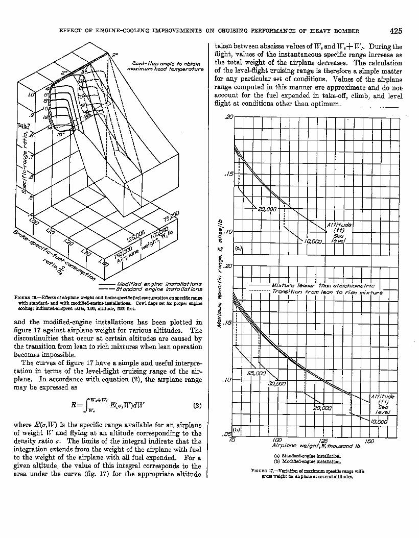
and the modified-engine instdations has been plotted infigure 17 against airplane weight for various altitudes. Thediacont.inuities that occur at certain altitudes are caused bythe transition from lean to rich mixtures when lean operationbecomes impossible.
The curves of figure 17 have a simple and useful interpret-ation in terms of the level-flight cruising range of the ati-plane. In accordance with equation (2), the airplane rangemay be expressed as
R= J“+n”E(u,w)mrn’. (8)
where lZ(u, W) is the specific range a-raiIable. for an airpIaneof weight W and flying at an zdtitude corresponding to thedensity ratio a. The limits of the integraI indicate that theintegration extends from the weight of the airplane with fuelto the weight of the airplane with all fuel expended. For agiven altitude, the value of this integraI corresponds to thearea under the curve (fig. 17) for the appropriate altitude
taken between abscissa values of W. and W.+ Tl}. During thefright, valuw of the instantaneous specfic range increase asthe total weight of the airplane decreases. The calculationof the level-flight muking range is therefore a simple matterfor my particular set of conditions. I’alues of the airp]ane
range computed in this manner are approximate and do notaccount for the fuel expended in take-off, climb, and levelfight at conditions other than optimum.
l\l I it lx\l I f I I I Illilll
.10
(a) Stimdmd-en.gheinstallation.(b) 3fodiEed@e instdletion.
FIGIXE 17.—VeriaH0nof maximum speeidcrengewithgrasswdght forrdrpIeneatsererelaltitudee.
426 REPORT NO. S60 .—NATIONAL ADWSORY COMMITTEE FOR AERONAUTICS
$.>F
Q’g
$Q
o 10 2f7 30 40Fuei weigh f, W,, fhousan d lb
(8) Standard+ngfneinablletfon.(b) Mcdltled+ngtnefnetrdletion.
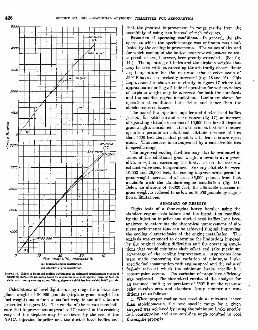
FIGUEE lS.-Effect of improvedeoolfngpfrformanwon esthnat.ederufaingrangeateeveraleltltndeq thexetfmlestfmateabaaedonnraxhrmmcalanlritedsLMcfdcrengaforboth hr.Walletlon& Army summerair ccmditiona;airpleneweightlesefuelweight,W,WOpounds.
Calculations of level-flight cruising range for a basic air-plane weight of 90,000 pounds (airplane gross weight lessfucI weight) made for various fuel weights and alt.itudes arepresented in figure 18. The results of the calculations indi-cate that improvement as great as 17 percent in the cruisingrang e of the airplane may be achieved by the use of theNACA injection impeller and the ducted head baffles and
that the greatest improvement in range results from thepossibility of using lean instead of rich mixtures.
Extension of operating conditions,—-In general, the air-speed at which the specific range was optimum was unaf-fected by the cooling improvements, The values of airspeedfor which cooling of the hottest rear-row exlutusbvalve seaLis possible have, however, been grca,tly ext~ded. (See fig.14.) The operating altitudes and the airphum weight~ th~tmay be used without exceeding the arbitrarily chosen limii-
ing temperature for the rear-row fxhaust-valve scats of
560° F have been markedly increased (figs. 15 and 16). l’his
improvement is shown more clearIy in figure 17 where the
approximate hrniting altitude of operation for various vttlucs
of airplane weight may be obsened for both the stan&wd-
and the modified-engine installation. l&it.s arc shown for
operation at conditions both richer and Icancr than the
stoichiometric mixture.
The use of the injection impeller and ducted head baM~~permits, for both lean and rich mixtures (fig. 17), an increaseof .oye.rating altitucle in excess of 10,000 feet for all airpktno.gro~ weights considered. It is also evident Lhfit rich-mixtmwoperation- permits an additional altitude incrcasc of lcssthan 5000 feet above that possible with lean-mixturo opPr-ation. This increase is accompanied by a considcrablct 10SSin specific range.
Tb improved cooling facilities may also be cvaluatwl interms of the additional gross weight allowable at a givenaltitude without exceeding the limits set on tho rear-rowexhaust-valve-seat temperature. For any altitude Wwccn10,000 afid 25,000 feet, the cooling improvements permit agro=-weight incre~e of at least 35,000 pounds from thatavailable with the standard-engine installation (fig. 18) ~Below an aItitude of 10,000 feet, the allowabIe increase ingross weight is reduced to as low as 10,000 pounds by enginepower limitations.
SUMMARY OF RESULTSFlight tests of a four-engine heavy bomber using the
standard-engine installations and the installation rnodificdby the injection impeller and ductd head baflks have Ixxwanalyzed to determine the theoretical i.tnprovernrnt of air-plane pe.rfonnance that can IM achieved through improvingthe cooling characteristics of the engine instaHat ion. Theanalysis was extended to determine the limitations imposed
“by the original cooling difficulties and the operating condi-tions that would tinimize their effect and take maximulnadvantage of the cooling improvements. Approxima[ jonswere made concerning the variation of minimum brakespecific fuel consumption with engine speed and thu valur offuel-air ratio at which the minimum brake spmifk fut’1consumption occurs. The variation of propulsive cflicirncywas neglected. The theoretical results of tic analysis foran assumed limiting temperature of 560° F on the rear-rowexhaust-valve seat and standard &my summer air con-ditions tie as follows:
1. Whim proper cooling was possible at mixturrs leanerthan stoichiometric, the best specific rango for a givenakspeed was achieved tiy using the minimum brake specificfuel consumption and any cowl-flap angle required to coolthe engine properly.

EFFECT OF Eh’GIh’E-COOLING IMPROVEMENTS
2. When proper cooling was impossible at mixtures leanerthan stoichiometric, the best speci.tic range for a given air-speed was achieved by using a covd-fla.p angle of approxi-mately 5° open and the leanest mixture that aIlows proper
cooling.
3. The maximum airplane speci6c range (and, conse-
quently, the ma.fium cruising range) was always attained
with the appropriate e mixture-cowl flap combination and
an airspeed corresponding to the maximum liftdag ratio,
if the airplane flying altitude was stable at this point.
4. For flying conditions at which the specifio range of the
standard airplane is seriously reduced by large cooling re
quirements, engine-inst.allation analysis indicated that the
specific range was, in an extreme case, increased as much
as 38 percent through use of engines employiug the injec-
tion irnpeIIer and ducted head baffles.
5. Analysis of flight-test- data indicated that improvement
in engine cooling performance through use of the NACAinjection impelIer.and ducted head baffles aIlovred an increasein operating altitude in excess of 10,000 feet or &gross-weightincrease of from 10,000 pounds at sea. Iewl to at least 35,000pounds above 10,000 feet tithout exceeding an e.ihaust-
valve-seat temperature of 560° F.
,
AIRCRAFT ENGINE RESEARCH IXBORATOEY,
hTATIONAL ADVISORY C OWITTEE FOR AERONAWCSZ
CLEVELAND, OHIO, Jfarcil 14, 1946.
ON CRULSING PERFORMANCE OF HEAVY BOMBER 427
REFERENCES
1. Marble, frank E., Ritter, WiUiam K., and ~liIler, Wblon’ A.:Effect of ~ACA Injection ImpeIIer on ~iixture Distribution ofDouble-H.aw Radial Aircraft Engine. NACA Rep. hro. S21,1945.
2.Sipko, Michael A., Cotton, Charles B., and Lusk, James B.: the ofDucted Head Ba&e to Reduce Rear-Row Cylinder Tempera-t ura of an Air-Cooled Aircraft Engine. hTACATN h’o. 1053,1946.
3. Marble, Frank E., Miller, Mablon A., and YenseI, Joseph R,:Effect of NACA Injection Impeller and Ducted Head BafflesonFlight Cooling Performance of DoubIe-Row Radial Engine inFour-Engine Heavy Bomber. NACA 31R No. E5D13, Army AirForces, 1945.
4. Kerber, L. V.: Induced Drag and Equivalent Monoplane AEpectRatio. VOLV of Aerodynamic Theory, div. O, oh. II, sec. 3,_iV.F. Durand, cd., JuIius Springer (Berlin), 1935, pp. 230-232.
5. Reed, i$lbert C.: Airplane Performance Testing at Altitude. Jour.Aero. Sci., VOL8, no. 4, Feb. 1941,pp. 135-150.
6. Allen, Edmund T.: Flight Twding for Performam% and Stability.Jour. Aero. Sci., vol. 10, no. 1, Jan. 1943, pp. 1-24; discussion,pp. 25-30.
7. ‘iVyatt, DeMarquis D., and Coma& E. ‘AllIiam: An Investigationof CoW1-Flapand CowI-Outlet Designs for the B-29 Poire~Plant ,Installation. NACA MR No. E5K30a, Army Air Forces, 1946.
8. Katzoff, S., and Finn, Robert S.: Determination of Jet-BoundaryCorrections to CowIing-F1ap-Outlet Preesm by an ElectricalAnalogy Method.. NACA ARR NO.4B23, 1944.
9.Pinkel, Benjamin: Heat-Transfer Procee.sesin &-Cooled EngineCylinders. NACA Rep. N’o. 612, 1938.
10. Pinkel, Benjamin, and Rubert, Kennedy F.: Correlation of WrightAeronautical Corporation Cooling Data on the W335&14 Inter-mediate Engine and Comparbon m“th Data from the Langley16-Foot High-Speed TunneL NACA ACR NO. IZ5A18, 1945.
842951—5%29