Saturn V Launch Vehicle Flight Evaluation Report - AS-511 Apollo 16 Mission

REPORT No. 511
THE EFFECT OF BAFFLES ON THE TEMPERATURE DISTRIBUTIONAND:HEAT-TRANSFER COEFFICIENTS OF FINNED CYLINDERS
By OSCAR W. ScmY and VmtN G. ROLLIN
SUMMARY
An investigation w made to detemvine the e~eot ojba~ on the temperature dbti”lndion and i?he heat-tran.sfer coejici.eni of $nned cylinders. The tests w~econductedin a 30-inch wind tunna?on electrically lwakdqIlin&rs un”th$rw of 0.26- and 0.31-inch pitch.
Four types oj ba~es were tested: Plata mounted aivarious positions around the cylinder and at vum”owsangle8 &h respect to the air stream; etream.lim baflesmounted near the rear oj tti cylinder; 8JW bafles withvariody 8huped opening8 mounted around the testcylinder wmetrically w“th reqect to a plane throughthe axix of the cylinder and parallel to the air 8tream;anditiegd ba~ COVLp08d Of &p8 w&kd to the tip8 Of the
fins oj the ted c@nder to form pa38a@ between the jh.s
throughwhich the air cd~ to therear of the ylinder.% resuU8of th.ae te+v%showedthat th w-seof integral
bajl.es gaoe a redudion of 31.9 perceni in the rear-walltemperaturesand an inmeme of 64.,9percent in the heat-tran+?ercocj%kni m compared un”tha qdinder wii%mdba~.
Although the ejects of th 8heUba& were not @ totho8eof the integral bajiks, they gave a large reduction inrear-waUtempmaiuxexand a furge inmeme in tlw heai-transfer coej@ient. The best resuli%were obtained witht?u 8heUbajl?e8mouniedin contactwith tti$w, when theintake opening was equal to the arc subtendedby an angleof apprm”mately 146°, when the e.rien.siomwe 3 inchesor mare in Lengthtand when the ratw of exit area to areabetweenjins waa approximu#eJy1.6. The heut-tramjfer
toe+ with the be&8heUba~ variedas the air sptxdtO th 0.86 pOWIW.
INTRODUCTION
The present trend in air-cooled engine design towarddecreased frontal area and greater speeifk-powwr out-put requires that all possible means be investigated forincreasing the efficiency with which waste hed is dis-sipated from the cylinder to the cooling air. A studyof the air flow around a conventional air-cooled cylin-der exposed to an air stream shows that the air followsthe surface for nbout 100° from the front after whichit breaks away from the cylinder, with the result thatcooling at the rear is very poor. Considerable improve
rneit in cooling can be obtained by the use of bwillesaround the cylinder to insure that the air follows thesurface of the cylinder for a greater distance before thebreakaway occurs.
In the fit cowling tests conducted by the Commit-tee the cooling was improved by using baille-s(reference1); recent tests have been conducted elsewhere on va-rious types of bafk. (See reference 2.) The results ofextensive flight tests by Higginbotkun (reference 3)showed the shape and location of the bafk to be veryimportant in obtaining the mtinm cooling with theminimum drag. BaEles are generrdly used in conjunc-tion with N. A. C. A. cowling; they improve the cool-ing by directing the air to the hot parts of the cylinderand they reduce the drag by limiting the quanti~ ofair that flows through the cowling.
The purpose of the tests herein reported was todetermine the shape and location in relation to thecylinder barrel of the baflk that give the largest im-provement in cooling. TIMts were made with platebailles set at various anglca with respect to the tistream and at various positions around the cylin-der, with streamline bafk, with shell bailles havingvariously shaped entrance and exit passages, withbafk welded to the tips of the fins, and with com-binations of shell bailles with strips inside the baffles.A few tests were also made of a cylinder having thefins bent at the front quarter to an angle of 50° withrespect to the cylinder wall. Most of the tests weremade at an air speed of 56 miles per hour; some data,however, mire obtained at air speeds from 38 to 145miles per hour.
The comparative coolhg of electrically heated finnedcylinders with and without bailks was obtained bytesting each cylinder and baftle combination in a windtunnel and meaanring the temperature over the coolingsurface for a given heat input and air speed. Thecomparison of the effeetivenw of the various tgpes ofbailles was based mainly on the heatAransfer coeffi-cient (the heat dissipatedper unit of cooling surface perunit of time per unit of temperature d.illerence be-tween the cooling surface and the cooling air). Thereduction in base temperature at the rearof the cylinderwith the vsxious types of baflles was also considered.
111

112 REPORT NATIONAL ADVISORY COMMITPEE FOR AERONAUTICS
The testswere conducted at the Committee’s labora-tories at Langley Field, Vs., between July 1932 andOctober 1933.
APPARATUS
Cooling tunnel.-The cool@ tunnel used had a30-inch threat and was desigged to give air speeds upto 200 miles per hour. The air speed of the tunnel was
stiction of such a unit is completely described inreferences 4 and 5.
A voltmeter and an ammeter were used for measur-@g the heat input to the test cylinder. Oil-cooledrheostats having a very sensitive adjustment over awide range of electrical input were used to regulatethe input to each of the guard ringe and to the testcylinder.
FIGUREL-Cooling tunnelwfth one of the &t unfts mmmtei in Pka
measured with n pitot+tatic tube placed to one sideand sufficiently far ahead of the test unit to assure theaccuracy of the readings. A honeycomb grid wasplaced at the tunnel entrance to reduce air disturb-ances. Figwe 1 shows the cooling tunnel with oneof the test units mounted in place.~ Test units.—The tests were conducted with threetest units of the type shown in figure 2. The heating
Thermocouples.-The temperatures of the surfacesof the finned cylindem were measured with iron-cxmstantan thermocouples connected through a se-lector switch to a medium-resistance pyrometer of theportable type. The thermocouples were made of0.013-inch diametar silk-covered enameled wire.
The 24 thermocouples were electrically welded tothe barrel and the fins at the positions shown in figure
End fairing Imer ~d,ring hemhg M ,#32” asbesfos separafcr
Tesf cylihder
FIGURE2—DetalMof amtnmtfon of the &t rink,
unit for the cylinders coneisted wentially of a coil ofnichrome wire embedded in alundum cement. Thecoils of the heat@ element were so distributed that.the heating was uniform over the entire cylinder wall.In order to eliminate heat losses from the ends of thetest cylinder, guard rings of the same construction asthe test cylinder were placed on each end. The con-
3. The temperature distribution being symmetricalwith respect to the air stream, the thermocoupleswere located on only one-half of the cylinder. Testshave shown (reference 5) that at any given position onthe fins the temperature is practically the same for allthe iins and that the results for one fin can be taken asrepresentative of all.

.
THE EFFECT OF BAFFLES ON THE COOL12TG OF FINNED CYLINDIIBS
Apparatus used for measuring air-flow speed.—Theair speed between the iins was determined frommeasurements made with impact and static tubes con-nected to water manometers. The tubes had an out-
Frcd
k- 22.5”..
m
i7eb
FImEE 3.—LaMon of thermomupks on test oyllnder.
side diameter of 0.040 inch and an inside diameter of0.035 inch.
Cylinders and baffles,-Figge 4 shows cross sectionsof the tins used in this investigation. The O.25-inch-pitch fins on cylindem 1 and 2 were of 1.22-inch and
‘6bv“
Cylln&er I Cylin+r’er 2~ C“i+w 3
FIGURE4.-ShaP of W and outstdewoll and tohk’m’fam areas on &t oyllnders
0.67-inch widths, respectively. Cylinder 3, which wascut from a Wright J–5 cylinder barrel, had fins of 0.31-inch pitch and 0.6-inch width. The cylinders wereconstructed from steel corresponding to specificationsfor S, A. E. 1050 steel. Figure 5 shows one of the
cylinders equipped with shell baffles
113
and attached tothe mounti& b~acket ready for testing.
The plate baftle (fig. 6) consisted of two platesmouted symmetrically on each side of the test cylin-der with respect to the plane through the axis of thecylinder and parallel to the air stream. Two sizes ofthese plates were tested, the narrow one being 1Xinches wide and the wide one 4X inches. The platebafiles and all other bathes tested were constructedfrom 20-gage sheet steel.
The streamline baflles (fig. 7) consisted of two piecesof streamline tubing symmetrically mounted parallel
I to the axis of the cyhder and 13+ from the &ont.
mmm&—Assembly of tlmod test OYlinder and gufud ringd with monntingbrat% bat%% and therm@m@e3 in Pb3C&
The shell brdlles (see fig=. S, 9, 11, 13, and 15) con-isted of two pieces of sheet steel of single curvaturenounted concentrically with the surface of the test)ylinder and symmetriwdly with respect to the cylin-ier diameter parallel to the air stream. Some of thesemilks were provided with extensions forming entrancemd exit passages.
As previous tests (reference 4) showed that the cool-@g was greatly improved by directing the cooling air}t an angle with respect to the ii.ns, it was believedthat @iiug the air to the rem of the cy~der ~d, atthe same time, directing it at an angle with respect tothe fins, would reduce the rear-wall temperatures.

.
114 REPORT NATIONAL ADVISORY
Narrow strips were accordingly placed at an anglebetween the baiiles and the b so as to direct the airspirally toward the rear of the cylinder as shown infigure 19. A section of the fins on cylinder 3 was bentat an angle of 500 to the cylinder wall in order toinvestigate further the cooling with the air directedat an angle with respect to the fins (fig. 20).
The integral brdlle (&g. 21) was a special shellbaflle constructed by welding strips of metal betweenand at the tin tips to form channels for the cooling air.
TESTS -
Tests on cylinders 1 md 2 were made with a heatinput of 85 B. t. u. per hour per square inch of coolingsurface and those of cylinder 3 with a heat input of100. The air speed for all the tests was approximately56 miles per hour except in the tests made to determinethe effect of speed.
When conducting this investigation preliminarytests were made with the plate, streamline, and shellbailles; as a rcmlt of these preliminary tests the shellbailies were selected as the most promising for furtherinvestigation. The wide and narrow plate bafikwere tested on cylinder 1. The narrow baiiles weretried at the front, side, and rear of the cylinder andfor each position the plates were teated at three dMer-ent angles with respect to the sir stream. The widebaf%s were mounted at the rear of the cylinder andtested at three angles to the air stream. The arrange-ment of the plates and the results of the tests are showntogether in figures 6 (a) to 6 (f).
The streamline bailles were tested with cylinder 1in the single condition shown with the resultsin figure 7.
Although most of the tests with the shell bafiies weremade on cylinder 3 (ilgg. 9 to 18), which had h of0.6-inch width, a sufEcient number of tests were madeon cylinder 1 (fig. 8), which had fins of 1.22-inch width,so that the effect of fin width on the heat+transfercoefficient and the temperature distribution could beestablished. The radial distances from the shellbaftlesto the h were varied horn 0.07 to 2 inches. The]~gt~ of fie efit efi~om ~~d on fie sh~ bafflwof cylinder 3 were varied frem 0.375 to 5 inches; thesize of the intake opening, eqmil to the arc subtendedby the angle, was varied from a minimum of 400 to amaximum of 210°. Determinations were made of theeffect of varying the ratio of the area of the flow pas-sage between the deflector and the cylinder to the dis-charge area from 1 to slightly more than 3.
The results of the tests made on cylinder 2 with shellbaiiies and with combinations of shell bailles and stripsto direct the air at an angle with re9pect to the iins areshown in figure 19. Tests were aleo made with andwithout shell btics .on cylinder 3 having a section ofthe fins bent so that the ceoling air would impingeupon the fins at an angle instead of parallel. The sec-tion varied in size from 90° to 360°, the small section
CO~ FOR AERONAUTICS
being tied at various points around the circumference.Only wall-temperature measurements were obtainedwhen testing this arrangement. (See fig. 20.)
A few tests were made on cylinder 3 to determinethe effect on base temperature of using bailles consi+ing of metal strips welded to the tips of the fins, Asketch of this baffle and the results of the tests areshown in &sre 21.
Tests were also conducted at several air speeds be-tween 38 and 145 miles per hour to determine whetherthe improvements obtained at one air speed with thebent shell bafEes could be obtained at other b speeds.A few tests were also made, for the same range of airspeeds, in which the air speed between the fins atseveral points approximately 90° from the front ofthe cylinder w-asdetermined with and without bdflea.
COMHJTATIONS
The calculations for this report are substantially thesame as those of reference 5 from which more detaileddescription and the derivation of the formula may beobtained.
The air speeds were corrected to a standard densitycorresponding to a pressure of 29.92 inches of mercuryand a temperature of 80° F. according to the relation:corrected air speed=
observed air speedx densi~ in tunnel test sectionstandard density
The cold junction of the thermocouple that meas-ured the temperature diilerence between the cylinderand the air was located outside the tunnel. A cor-rection was applied to take care of the adiabatic cool-ing of the air due to the drop in pressure before reach-ing the test section and the frictional heating of theair by the grid and tunnel wall ahead of the @tsection.
The average cylinder-wall temperature was foundby arithmetically averaging the readings of the ninethermocouples located on the cylinder wall.
The temperatures at any point on the surface of thecylinder wall and tins wme determined by cross-plo~ting the measured temperature. The average cool-ing-surface temperature was obtained by graphicallyintegrating the temperature with respect to the meriover the entire cooling surface and dividing by thearea covered.
The average surface heat-tiansfer coefficient waafound by dividing the total heat dissipated per hourby the product of the total exposed area of thecylinder wall and tins and the average surface-temper-ature difference. The experimental cylinder-wall heahtransfer coefficient was obtained by dividing the totalheat dissipated per hour by the product of the outsidecylinder-w-all area and the average cylinder-walltemperature diilerence.
For convenience in this report whenever “tempera-ture” is used it will be underatiod to mean the cor-

THE EFFECT OF 13AFFL0S ON THE COOLING OF FINNED CYLINDERS 115
rected ‘ttemperature difference” between a point onthe cylinder and the cooling air.
The theoretical cylinder-wall heat-trmsfer coefficientwas calculated horn the following formula (reference 6):
‘=w+a’daw’+”]
-J .zqwhere — E
U, over-ill heat-transfer coefficient, B. t. u. persquare inch base area per hour, per ‘F.temperature difference between the cylin-der wall and cooling air.
g, surface heat-trrmsfer coefficient, B. t. u. persquare inch total surface area per hour,per ‘F. temperature difference betweenthe surface and the cooling air.
k, thermal conductivi~ of metal, B. t. u. persquare inch, per ‘F. through 1 inch perhour (2.17 for steel).
t, average fin thiches-s, inches.P, pitih of fins, inches.W, fin width, inches.
W’=w+t$ effective fin width.
t~, fhl-tipthickness,inches.lt~, radius from center of cylinder to fin root,
inches.s’~, distance between adjacent fin surfaces at
the fin root, inches.The following additional symbols are used in this
report:~b, average temperature diilerence between the
root of the fi and the cooling air, ‘F.eaf average temperature difference between the
cooling surface and the cooling air, ‘F.
RESULTS AND DISCUSSION
PLATE BAFFLES
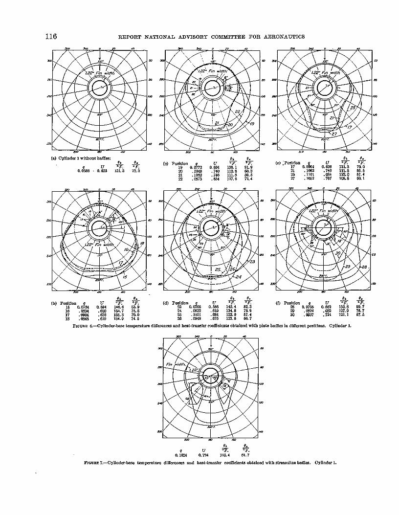
The effect on the temperatures of the cylinder baseof using plate baflk is shown by the temperature-distribution curves of figure 6. The dngle curve offigure 6 (a) is for cylinder 1 without baflles. Thetemperature-distribution curve and the heat-tramfercoefficients obtained for cylinders 1 and 3 (@. 9(n)) without baffles are used throughout this report asstandards for comparison. The condition of shellbaflles alone on cylinder 2 is used as a standard tocomprwe with the cylinder when strips are attachedto the baffles. (See fig. 19.)
When plate bafEes 1.25 inches wide am placed 45°from tho front, the second group of curves (fig. 6(b)) and the heat-tmmsfer coefficient show that thecooling is impaired for all conditions except when thebaffles are perpendicular to the general direction ofthe air stream, in which case the heatAransfer coeffi-cient was increased only 4.4 percent. The use of the
mflle plates on the sides of the cylinder at variousmgles with respect to the air stream caused a largemriation in the base temperatures as shown by the&d group of curves (fig. 6 (c)). The heat-transfercoefficient varied horn a reduction of 10.9 percenttith the plate9 parallel to the b stream to an increase)f 22.6 percent with the platm perpendicular to theti stream. The reduction in rear-base temperaturetith the plates perpendicular to the air stream wasmmll. When the plates are mounted 60° from the:ear of the cylinder (fig. 6 (d)) and perpendicular to;ho direction of the air stream, the heat-transfermflicient is increased 27.2 percent. Practically nowduction in rear-base temperature was obtained forihe latter condition but the temperatures at points>et-iveenthe tides and the rear show a large reduction.
Figure 6 (e) shows a comparison of the base tem-peratures obtained for the best condition at each ofthe three positions tried. The solid curve representsthe results obtained with two plates mounted on eachtide as shown. With the latter plate arrangement thebeatitrsnsfer coefficient is increased 21.5 percent. Therear-walltemperature is increased slightly but the wallbmperaturea at points between the sides and the rearme greatly reduced. The wall temperatures for thecondition with the btiea mounted 60° from the rearwrehigher than with “one or two bafllea on the sideBven though the heat transfer is higher. This apparentdiscrepancy is explained by the fact that the hea&trsnsfer coefficient is based on the average fin andbarrel temperature.
In generil, it may be said that the narrow platebafiles give a large improvement in cooling whenmounted perpendicular to the air stream and betweenthe side and rear of the cylinder but when momtedparallel to the air strewn they may seriously impairthe cooling. At best only a slight reduction in rear-wall temperature _ be obtained with the narrowbaffles. As this type of batEe is very sensitive to thedirection of air flow, great care must be exercised inits use or the cooling may actually be impaired.
The curves in &me 6 (f) show that the plate bafiles4% inches wide mounted 60° from the rear of thecylinder do not improve the cooling as much as do thenarrow plates (fig. 6 (e)). For the best condition withthe wide plates the heatitransfer coefficient was in-creased 8.7 percent as compaxed with an increase of27.2 percent with narrow plates mounted near the rearof the cylinder. When the wide plates were mountedparallel to the air stream the cooling was seriouslyimpaired, as indicated by an increase of 40° F. in therear-wall temperature. and a decrease of 18.6 percentin the heatAransfer coefficient.
STREAMLINE BM?PIJL9
The curves and data of @e 7 show that streamlinebaflies on cylinder 1 increased the heaMmmsfer co-efficient horn 0.0866 to 0.1024, an increase of 18.3
116 REPORT NATIONAL ADVISORY COMMITTEE FOR AERONAUTICS
(a) Cylinder 1 without Wlks:8}
~ aO& a.iJ & m%
oh& (o) PCUII (e) IPd;km %
-% “F.alfk
($!& + lZ H:. 0.‘m 13L3 72_3 21 111.8
21 .1062 Ill. 8 52 2s .1101 .W 122022
b~;.a3i3 :&’ 127.6 724 n . la52 .767 [email protected]
O& 8. oh
M& a: ;$ p~0.
(b) Pqi$on T =C&4 LIE&
(d) PculslUon (I) PGslBtiml w-%140.6 839 aO& Cltia lsas &9.7
16 13L7 75,817 %%J 2
20 .m ~~13L3
7a.7.1101 .6s4 1220 67.4
ls :E H’30
134.Q.W-7 .724 .
23 .0a48 .67667.6
1=6 69.7
PIGum &-OylInder~se temperat!me dUferenc& and Mat-trader ccmmdmta obtaind with Plat@batlka in dlfkent I?Atlom% Oylindw 1.
Swmo.v a
m m m.
u +% +.CL:024 0.724 116.4 6L7
FIGURE7.—CylInder-~ temp?ratnre dlthen~ and heat-transfer metlldents obtalxd with strmndlne baffle. Oyllnder 1.

THE IWFECYI? OF BAFFLES ON = COOIJNG OF FINNED CYLINDERS 117
percent, while the rem-wall temperate ~~ ~cr~~15° F., or 8.6 percent. Apparently with these bafbthere is, in the rear of the cylinder, a low-pressure areathat causes the air to flow h the rem through theopenings between the baflles and the cylinder.
SHELL BAF’FLW
The curves in figure 8 (a) show that although, withinlimits, increasing the extent of surface contact of theshell baffles with the cylinder so as to rcatrict the exitopening decreases the rear-wall temperatures, it also,for the two conditions shown, reduces the heaMwmsfer
A comparison of the results for test 4 in figure 8 (b)with those for test 3 in @e 8 (a) shows that withoutflares on the intake opening the heatAransfar coeilicientis 12.5 percent higher md the rear-wall temperatures10° higher than with flares.
The curve in figure 8 (c) shows that an appreciablereduction in rear-wall temperatures may be obtainedby using small badiea between the fi in conjunctionwith the shell bafb. As compared with conditionswithout baflk (fig. 6 (a)) this arrangement reducedthe rear-wall temperatures 15.4 percent; whereas the
R ob 0,(a) Test fn. c&. u T. v.
2 4)4 46 a$w 0.737IR2 6&23 1)4 30 .W7’2 .724 llks MO
0, .9. t% e.(c) u T. m
al%39 0.856 97.6(a) u =R q
5s5 && &424 23%1 i’m-i
RQW 0, e.(b) Test in. dcu. in. a u m m. .
4 1)4 w- 254 aiC%3 0.741 1EL6 67.8b x = 1’%6 .1656 .717 ll&4 69.9
FmUFLE&-Oyllnder-k-e taqmmtmm dfffermces
(d) v +. %.11:369 am 114.7 69.7
and h-transfer coa6Ments obtafmd with ehcdlbadim OYllnda L
coefficient from 0.1087 to 0.0972. A further reatxic-tion of the ti flow effected by reducing the tie of theexit opening (fig. 8 (b)) causw an increase in rear-walltemperatures and an additional reduction in the heabtransfer coeilicient. The results, however, show thatlittle difficulty will be experienced in effecting a laxgereduction in temperature at points between 20° and70° from the rear of the cylinder although it will beconsiderably more difiicult ta reduce the temperaturedirectly in the rem.
46 1 a 1-MI 0.474 XL 4 ma. 947 2 .1189 .49s m9 ml. 740 3% . IU22 .474 213.1 1726
FmUEE 9.—EffIxt of the wfdth of dt Ox of shellbatlke on the temmratum dfshibution and bent-transfer mefFMents. Winder 3.
shell bailles without the small baflles (fig. 8 (b)) gavea reduction of only 2.9 percent. For the foregoingconditions the heai%mmfer coei3icient increased 19.9percent with the small baiiles and 26.2 percent withoutthe small bties. Apparently these small baillcs arevery eflective in guiding the air toward the rear ofcylinders having long fins, but they impair the coolingat other points on the cylinder because they slow upthe air and cause a reduction in the heabtmmsfercoefficient.

REPORT NATION.UJ ADVISOItY COMMJTCEH FOR AERONAUTICS
with
0, ~ 0$Test {:. u Test: ~ L&
w “F. (b) TA {;. %cL& aws m9 MI-7
(a) u T “F.47 ao7 a&9
u “F.47 a a4fr3 m9 ML 7 61 2m a&71 a349 zL9.3 2430
‘Y35 .lma .’WI 20LQ Ifa 6 Ea ‘la .f@-m .ss3 233.3 225.1 63 .76 .C&Y3 .370 27L3 2%’.8
631 .Im .433 !23L8 19L9 07 .07 .1078 .453 218.3 17a 6
FfctcmmlL—Eff@t of tbelongth of tfM edt extonsfom of FIGURE13.-EW of @kronce botvmn the sbellbeJ3Mand the fln trip cmthe tompomtore dktr!hntfonendshellbadksonthetemperolnmdfshibntlon andbeat- heafihansfer cc=xlldents. Clylfnder 3.~ Coemclents. Cylhlder 3.

THE IOFF13CT OF BAFFTJEB ON TE13 COOLING OF FINNED ~13R.S 119
The results of the tests on shell bafiles have shownthat with proper installation of baflles an appreciablereduction in rear-wall temperatures md a large in-
1 I I I I.50 / —3 in& exf em icms
--------No .
I!&.46 \
.g ~’
62G?< .42 ,,> ----- \
i~L /’ \ \ \
3$‘.
.38~.
Q’- . . .
.---
---- --- --
- ---- -
.34
.118 ‘ --
.110 . \
bQ~.s (. /02 - \
t5$0-/< ,,-.
k
# ‘. \ii ‘t%094
,1
:$ ,/
ti /,‘N,
.066 “\ \
.---- ---- ----
-----..
‘.,.078
450---- ----- +~ ---
----,-
410
P ,$ >~OK /’
ii” 370 d~ m- ,1
~?,~
a t!t)u3~ ,/’ Ikk [I .-bb ‘x” /
4290 /
2500
Radia;%learon>~ befm% sbel}%m%le2.0
md fin tips, in&es
FIOIJBE14.—Vfoietfonof rear-wall tranxtmw end he&QaMf@r Ooefadmts withalmrenm Mtw@neheUtMks end flntf~ @ifm3er3.
crease in the heafitrrmsfer coefficient may be obtained.These results were sufficiently encouraging to warrantfurther work to determine the effect of size of exit
71fMo-3erJ
opening, length of extension, frontal area exposed toair stream, and the distance between baffle andcylinder.
Effect of exit opening,-The curves in figures 9 and10 show the importance of the ratio of exit area ofbsdlkwto the an% between the cooling surface and thebailiea in reducing rear-wall temperatures and increas-ing the heaktiansfer coefficient. Three tests were con-ducted on cylinder 3 (fig. 9 (a)). With baffles havinga ratio of exit area to cleax area betmeen fins of 1.75(@s. 9 (b) and 10) the rear-will temperature wasreduced to less than 260° F., or 13.3 percent, and theheatAmmsfer coefficient was increased 23.1 percent.In figure 10 the curve for the hem%rtmsfer coefficientshows an optimum ratio of areas of 2.3, which is higherthan the value of 1.6 based on the curve for rear-willtemperatures. The optimum ratio of areas is a ratiothat will give a large reduction in rear-wall tempera-ture by bringing the air as far as possible to the rearwithout appreciably decreasing its veloci~. These
a
m
m
m
I@
Test ~. w % %47 m flLFa am m9 lfiL 7w 14!3 .1233 .J51u 1’%.o lm. 47oz0. cW.40724s. oml
ROVES I&-E@ of the entianm @e of a sIMII bame 00 the teqmraturedletribntfen end Wtrensfer mdolenfs. Oylfnder 3.
ratios would be meaningless if the area of the flowp-e between the cylinder and the baille and theexit opening were greatly increased, unless there wasa corresponding increase in the cylinder diametar.
IHeot of extension length,-The curves in figures 11md 12 show that bailles having extensions 3 inches ormore in @ngth give the large9t reduction in rear-walltemperatures and the highest hwdAmmsfer coefficients.That the opt&mIu extension length is short iE fortu-nate, because long extensions would increase installa-tion difficulties; whereas3-irichextensionscan probablybe conveniently used on all installations. The irregu-larities in the curves of rear-wall temperatures andheat-transfer coefficient when extensions shorter than3 inches axe used indicate that the length of the exten-sion has considerable effect on the air flow in the rearof the cylinder and that the cooling can be regulatedby slight changes in the extension length. Increasing

120 REPORT NATIONAL ADVISORY COMMITTEE FOR AERONAUTICS
.
the length of the extension to more than 3 inchesresults in a gradual increase in rem-wall temperaturesand a small increase in the heatAransfer coefficient.
Effect of radial clemmce between baflles and iintips.-The test results shown in figures 8 (b), 8 (d), 13,.
/ -—1.
1 1 \
En frvnce ungle, akgrees, B
~OURE 16.-VarMfon of rff!r-wdf t8m~ ti ti~ CmJIMlmts W’itllenh’anm angle of ah8u IMo31eu Oylhldar 3.
and 14 indicate that the distance between the bdlleand the cylinder influences the mwr-wall temperaturesand the heat-tmmsfercoefficient g and that the amountof the cl&nge depends upon the h width. Phwingthe baflles in contact with the&on cylinde~ havingfins of 1.22- and O.O-in@ widths resulted in increases
in the heat-transfer coeilicient of 26.2 and 23.1 per-cent, respectively, as compared with conditions with-out baflles. Increasing the distance between thebaffles and the cylinders to one-half inch resulted inthe reduction of these percentages to 22.2 and 9.84 forcylinders having fins of 1.22- and 0.6-inch widths, re-spectively. The rear-wall temperatures of the cylinderwith the wide fins are not appreciably aflected by theuse of baflles regardless of the distance between thebaffh and the cylinder; whereas, for the cylinder hm--ing fins 0.6 inch in width the rear-wall temperaturesare reduced from 298° F. without baflles to 259° l?.with batlies in contact with the ii.ns.
A shell baflle with 3-inch extensions may seriouslyimpair the cooling if it is mounted too far from thecylinder (fig. 13 (a)). For example, when the bafflesare mounted 2 inches from the cylinder the rear-walltemperature is 104° F. higher than for conditions withno bafflm and the heat-transfer coefficient is reducedfrom 0.0965 for a cylinder without baffles to 0.0800 fora cylinder with bailles having extensions. The curves(fig. 14) also show that considerably more is to begained in reducing rear-wal temperatures and increas-ing the heat-transfer coefficient by placing bnffleawithexten&ons in contact with the fins than can be gainedby placing plain baiiles in contact with the h.
ERect of sise of intake opening.-A comparison ofthe CUIXWin figures 9 (a), 15, and 16 shows that theentrance angle has a large effect on the value of theheahtrmwfer coefficient. For example, with an en-trance angle of 145° (fig. 16), the herWmmsfer coeffi-cient was 0.1240 as compared with 0.0966 withoutbailb (fig. 9 (a)), an increase of 28.5 percent, Forthe same entrance angle the rear-wall temperature was250° F. as compared with 298° F. without brdlkw. In-creasing the entranm angle to more than 160° resultsin a sharp rise in temperature because the air breaksaway from the cylinder before it reaches the bdlle;whereas reducing the angle to lees than 120° results inonly a gradual increase in temperature, the speed beingreduced because of increased length of passage and be-cause the intake opening normal to the air flow issmaller.
The curves (fig. 16) for heatAmnsfer coefficientshow the same trend as the curves for base tempemture.When the entrance angle is increased to 210° the tem-perature in the rear of the cylinder are the same aswithout a brdlle, while the heatAramsfar coefficientshows an increase of 9.1 percent, indicating the bene-ficial effect of bafflea on the temperatures at otherpoints.
Although these tests indicate (fig. 16) that the heat-transfer coefficient decreases when the entrance angleis 1* than 120°, it is believed that on installationshov-ing a large part of the area between the cylindersblocked or on engines having cowling and baffle ar-rangement such that only sufficient air is admitted tocool the engge, angles less than 120° will give better
.

cooling. Improved
TEO EFFECT OF BAFFLES ON THE
cooling with small entranw angleis obtained for the above-mentioned condition becausethe air speed will be higher over a large part of thefront mea of n cylinder. For tests herein reported theair speed over the front of a cylinder with bafk wasprobably about the same as for a cylinder withoutbafllea because the air could flow freely over the out-side of the baflle as well aa on the inside.
Effect of air-stream speed.—The test results sub-mitted in figure 17 show that the heat-transfer coefE-cient vaxied as the speed to the 0.85 power for condi-tions without baflles and with bafiles of the type shownin figure 16. The tests ~ere made on cylinder 3 atseveral air velocities from 38 to 145 miles per hour.
.30
.20
b
k /<./0 / ‘1 I/“ / ‘ II&z { I
n = 0,85<’~’.o7
~TAb ba.. .. . II v I I I I I
. I I xl“’dIllrt-floc.~ .06QJQ. 05c,.tj..o4QL$.03 -
I I
t
Air speed, m.p.h.
FxIU8B 17.–Et?ent of afr @ cm the hsabtranafer cc.?fffdent Ofcylfnder 3 wftband WfthOUtShd kdkl
The use of the best shell bafliea resulted in a largeimprovement in cooling at all air velocities investi-gated. The test results in figure 18 show the effect ofvelocity on the cylinder-wall heat-transfer coefficient Ufor cylinder 3 with and without bafb. The calculatedvcdues of ‘U (equation (l)) are also shown. As thesecalculated values check the experimental values, themethod proposed in reference 5 for the de&n of cylin-ders without ba.filescan be extended to the design ofcylindem with bailles by using the experimental valuesof q as determined for cylinders with baflles.
The measurement of the sir speeds between thefins at 90° from the front of cylinder 3 without bafllesshowed ‘that the average air speed between the hwas 36 percent higher than the tunnel air speed.
COOLING OF FINNED CYLINDERS 121
With the best shell bties having a radial cleammcebetween the bailie and the h tip of 0.07 inch, theaverage air speed between the fins was 30, 92, 118, and172 miles per hour for tunnel air speeds of 30, 80, 100,and 140 miles per hour, respectively. At a tunnel airspeed of 100 miles per hour the highest air speed be-tween the fins without the baffles was approximately0.12 inch from the root of the iin and with shell bafllesit was approximately 0.09 inch from the root of thefin. This difference would indicate that part of theimprovement in cooling obtained through the use ofbaflies may be attributed to reduced boundary layer.
1.0I I
E~imenf al‘---------- Calculated
.8 /I 1
hb boffles / + ‘“/ --/-
~--.
.6b
/k
/ ‘
$
/
< .4 //
~
&-~zQ1?1. oc.-
Z
k.8 ‘
---i’ ~,
; ~.>
.6.
@-
//
.4 /
230 50 70 .90 110 130 150
Air speed, m.p.h.
FIQUM ls.-c0mpw’fKm of eqxfnmntal With calc?lhlted over-on IEabtmlsfw
amffkdont la aylfnder 3 with and wfthcmt shell bafllm at varlons air _
The curves in figures 9 (a) and 15 show that the tem-perature are reduced at a position 90° from the frontwhen using baffles as compared with conditions withoutbaffles even though the average air speed between theb is less, indicating that the boundary layer at thispoint is less on the cylinder with baflk.
COMFUNATION OF SHELL BAFFLES AND STRIPS
The results in figure 19 for shell baflies show that theaddition of the strips increased the wall temperaturesaround the rear of the cylinder, as compared with thecylinder with only the shell baiile, and that the heafitransfer coefficient was decreased. As the strips wereplaced on the fin tips, the air passing over the fins

122 REPOIW NATIONAIJ ADTTSORY
probably did not change its direction of flow and,furthermore, the speed of the air betweeu the cylinderand the baflie may have been reduced by a restrictingaction of the stips.
COMBINATION OF CYLINDER WITH BENT FINS AND SHEZLBAFFLES
Next to the integral bafiie, the combination of bentflus and shell baflles reduced the rear-wall tempera-tures more than any other btie. Complete data werenot obtained for these tests so that only the wall tem-peratures are given in figuxe 20. The rear-wall tem-perature was reduced from 298° 1?.for a cylinder withstraight h and no baftles to 210° F., or 29.6 percent,as compared with the 31.9 percent reduction obtainedwith integral bailles and 16.1 percent reduction ob-tained with baffle 69 (fig. 15). It should be noted that
COMWZTHE FOR AJIRONATXIZCS
cooling obtained with this type of baflle with andwithout extensions Waasmall.
CONCLUSIONS
The results of these tests show that:1. Properly installed shell baflles reduced the cylin-
der-wall temperature and increased the heat-transfercceflicient to a greater extent than either plate bdlesor streamline baffles.
2. Optimum cooling was obtained with shell baffleawhen they were mounted as closely to the cylinder aapossible, when the entrance was equal to the arc sub-tended by an angle of approximately 145°, when therearward extensions were 3 or more inches long, andwhen the ratio of exit area to free-flow area betweenthe iins was between 1.6 and 2.3.
+, 0. 0,Teat Camblnetfon u w ~F.
Ob 63
40 BG1-Aat W O.~W fL&c3 146.2Test Ddptien T F. T* u “F . J..
llL 8 A. Stxafghtf@ n0b8f6es --------- 22.214f BCahne . 1X33 .@! 125.9 lfe.4
No baftfs a~ 0.48! 23!31 lUS.8B. 8kakht 5n& with bafW -------- 197.6 n .14%3 .6s3 167.0 1’23.0
42 BC+Aat W .1057 .W 149.4 1121 0. Bent fm& no kaflfes_-.—.-_-.. !2f0.9D. Bent flnsj with baIT18Y.--__.__... 17U.O Raum 2L—Cyllnde@waU tam~ttu’m ond heat
FIGURE19.-Eff@ Of tip between shall baftka and tmnsk ccalldenta obta!nd with lntemtd batiks.tln tiLU on the tampere.bxe dfsbibntian and W FI13WEE28-EffW on the h tampamtmcs of Mnd- Oyllnder 8.-lx OMIMent. 0Wnd8r 2 inge. s&Monof thednsat aWm@etotheoylinder
waJL Oyllmk 3 with and wfthont ba$k
if the pitch of the iins were less than those used inthe test cylinder it might be detrimental to the coolingto bend the iins as much as 50° at the front, becausethe smaller the pitch and the greater the angle thesmaller will be the opening behveen fins for the air toenter and to flow across the fins.
lT4TEGR~ B~E9
The base temperatures were reduced at all pointsaround the cylinder with integral baillw as comparedwith the cylinder without baflles, the reduction beingthe greatest that has been attained in any of the baflietests. The rear-wall temperature was reduced from298° F. to 203° l?., or 31.9 percent, and the heabtransfer coefficient was increased horn 0.0965 to 0.1488,or 54.2 percent. The largest reduction in rear-walltemperature obtained on any of the other baffles w-asapproximately 15 percent. The great improvementwith this integral batlie can no doubt be partly attrib-uted to the increased cooling area. The difference in
3. The surface hea&tremfer coefficient with andwithout baflles varied as the 0.85 power of the airspeed for a range of speeds from 38 to 146 miles perhour.
4. The average air speed 90° from the front rmdbetween the fins of a cylinder with the beat shellbafHeawas less than for a cylinder without bailka, butit waa greater than the tunnel airspeed when the tunnelair speed was over 30 miles per hour. The highest airspeed between the fins at a tunnel air speed of 100miles per hour was measured at a point approximatelyO.O9and 0.12 iuch from the root for the conditionswith and without baflk, respectively.
5. The theoretical formula for calculating the heatdissipated from finned cylinders fitted with baffleschecked closely the heat dissipation determined experi-mentally.
6. Baflks welded to the tips of the fins gave thelargest reduction in rear-wall temperature and thegreatest increase in the heat-transfer codicient; the

THJ3 EFFECT OF BAFFLES ON THO COOLING OF ~ CYLINDERS 123
reduction in rear-wall temperature was 31.9 percentnnd the incrense in heat-transfer coaf6cient ma 54.2percent rw compared with the same cylinder withoutbaiilea.
7. Bendng the fins in the front quarter of the cylind-er to an angle of 50° resulted in a large improvementin cooling for conditions with and wh%out bailk.
LANGLEY ME~OEm AERONAUTICAL LABORATORY,
NATIONAL ADVISORY COMMITTED FOR ikDRONAUTICS,
LANGLEY I?IELD, VA., September 26,1934.
REFERENCES
1. Sahey, Omar W., and Biermann, Arnold E.: The El&at ofCowling on Cylinder Tempera& and Performmme of aWright J-5 Engine. T. IL No. 332, N. A. C. A., 1929.
2. Beisel, Rex B., MacOlain, L Lewis, and ThOIOfiS, F. M.:The Cbwling and Cooling of Radial AiKboled AircraftEnghw. S. A. E. Jour., May 1934j VOL34, no. 5, pp. 147-166.
3. Higginbotbam, IL R.: Enginc4uoling Problems withVenturi Cowling. S. A. E. Jour., Feb. 1932, vol. 30, no. 2,pp. 8G92.
4. Sohey, Oscar W., and Biermann, Arnold E.: Heat Dissipa-tion from a Firmed Cylinder at Dtierent Fin-Pkme/Air-Stream Angles. T. N. No. 429, N. A. C. & 1932.
5. Biermmm, Arnold E., and Pinkel, Benjwnin: Heat Transferfrom Finned Metal Cylinders in an Air Stream. T. R.No. 488, N. A. C. & 1934.