
REPORT No. 503 - Digital Library/67531/metadc66159/m2/1/high_res_d/19930091576.pdf · REPORT No....
17
REPORT No. 503 THE EFFECT OF SPRAY STRIPS ON THE TAKE-OFF PERFORWCE OF A MODEL OF A FLYING-BOAT HULL By STARRTNJSC~ SUMMARY The efed on th8tukwj performunze of a model of the hull of a typical flying boat-tlw i%oy PH-1-of jiiting 8pray 8trip8offour di$ertmiwidths, each d three di$ereni angla, waa determind by model tests in the N.A.C.A. Tank. spray 8irip8 of uridth$up to Spemerdof the beam improve the generalpaformanee ai .qwed.enear the hump and redwcetlw spray thrown. A downwardangle of 90° to&’ in tk? neighborhoodof the etep seem meetfavorable for the redwcti.onof the spray. Th4 spray 8trip8 have a large e$ect in reducing the trimming moments a# 8peed3 near tlw hump 8peed, bui luwe lWe e$ect on them at high speeds. INTRODUCTION The progress of any craft along the surface of the water at any but the very slowest speeds is accom- panied by the formation of waves and spray. If the vessel is of large dimensions relative to its speed the disturbance may be relatively slight, but as the size for a given speed decreases the disturbance increases in relative intensity. k the case of flying boats and sea- planea the formation of waves and spray during the take-off run may assume a particularly inconvenient form. If the hull has a round bottom a sheet of water may follow right up the sides and curl over inboard un- til rutthe stern the two curls may meet to form a high roach (reference 1). If the hull has a stepped V bottom, with sharp chines where the bottom meeiwthe sides, the tendency seems to be for the watar to run up the V bottom in a sheet and to be carried well beyond the beam of the hull in Rtrajectory by the momentum acquired under the bottom. This sheet of water usually rises high and breaks up into smaller maases that may be picked up by a propeller, or by the wind, and carried at high speed through the propeller or into parts of the airplane structure. Although no imme- diate damage may result, there is always danger of it (references 1 and 2). An obvious method of suppressing the spray is to fit strips, or battens, along the chine of the hull to oatoh the risii sheets of water and deflect them downward. Such strips, or battens, are referred to as “mudguards” in what appear to be the earliest tests of models in which they were incorporated (referenocs 3,4,and 5). These stips maybe either narrow fi.m projecting from the chines or rectangular, or tziangdar, strips on the bottom just inside the chines. (See sees. L and M, reference 1, p. 32.) An equally obvious method is to build the form of the strips into the bottom, giving the section of the bottom jud inboard of the cbi.nea curve to which the outboard tangent is either horizontal or slopes downward. This construction provides a deflecting surface in the bottom and does away with any fitted-on construction, - but at the same time necessitates the bending of frames and plating and increases the difficulty of either plating or planking the bottom. The straight V bottom with a spray strip in the form of a projecting fln at the chine appears to have the virtue of simplicity, but no published information has been found that gives a clue to the proper width and angular setting of such a strip to obtain the maximum reduction in spray thrown or tells how the width and angular setting of the spray strip tiect the perform- . ante on the water. Each user has accordingly followed his own ideas as to the widths and angles to be given to the spray strip. The purpose of the tests described in this report was to determine the effect of fitting spray strips of various widths and at various angles on a model of the hull of a flying boat that had a good performsmceon the water and in the ak by comparing the results of twts in those conditions with tests made with no ~ray strips in place. A )&&size model of the Navy PH-1 flying boat was available for this work. The tests were cotied to the one model. It has a form of bottom that maybe said to be generaly similar to that found on most American flying boats.. This model was tested with no spray strips and with spray strips of four different widths, eaoh at three diflerent anglw at the step. In 4 condition the model was tested both free to trim and at three angles of iixed trim. All the tests were made in the N.A.C.A. Tank at Langley Field, Va. The work of testing and working up remdtawaa done at intervals in 1931,1932, and 1933. APPARATUS AND METHODS The model,—The model was the one used in previous teds to determine the effeot of “flutes” in the bottom and of “hooks” on the step, demribed in reference 6. It was constructed of pine from lines and offsets sup- plied by the Hall-Aluminum Aircraft Corporation and was made to a scale of 2 inches= 1 foot, or % W size. A sndl hook on the step, which is present on the full size, was omitted on the model. The surfaoe of the model was painted with several coats of Navy gray 523
Transcript of REPORT No. 503 - Digital Library/67531/metadc66159/m2/1/high_res_d/19930091576.pdf · REPORT No....

REPORT No. 503
THE EFFECT OF SPRAY STRIPS ON THE TAKE-OFF PERFORWCE OF A MODELOF A FLYING-BOAT HULL
By STARRTNJSC~
SUMMARY
The efed on th8tukwj performunze of a model of thehull of a typical flying boat-tlw i%oy PH-1-of jiiting8pray 8trip8offour di$ertmiwidths, eachd threedi$ereniangla, waa determind by model tests in the N.A.C.A.Tank. spray 8irip8 of uridth$up to Spemerdof the beamimprove the generalpaformanee ai .qwed.enear the humpand redwcetlw spray thrown. A downwardangle of 90°to&’ in tk? neighborhoodof the etep seem meetfavorablefor the redwcti.onof the spray. Th4 spray 8trip8 have alarge e$ect in reducing the trimming moments a# 8peed3near tlw hump 8peed, bui luwe lWe e$ect on them athigh speeds.
INTRODUCTION
The progress of any craft along the surface of thewater at any but the very slowest speeds is accom-panied by the formation of waves and spray. If thevessel is of large dimensions relative to its speed thedisturbance may be relatively slight, but as the size fora given speed decreases the disturbance increases inrelative intensity. k the case of flying boats and sea-planea the formation of waves and spray during thetake-off run may assume a particularly inconvenientform. If the hull has a round bottom a sheet of watermay follow right up the sides and curl over inboard un-til rutthe stern the two curls may meet to form a highroach (reference 1). If the hull has a stepped Vbottom, with sharp chines where the bottom meeiwthesides, the tendency seems to be for the watar to run upthe V bottom in a sheet and to be carried well beyondthe beam of the hull in Rtrajectory by the momentumacquired under the bottom. This sheet of waterusually rises high and breaks up into smaller maasesthat may be picked up by a propeller, or by the wind,and carried at high speed through the propeller or intoparts of the airplane structure. Although no imme-diate damage may result, there is always danger of it(references 1 and 2).
An obvious method of suppressing the spray is to fitstrips, or battens, along the chine of the hull to oatohthe risii sheets of water and deflect them downward.Such strips, or battens, are referred to as “mudguards”in what appear to be the earliest tests of models inwhich they were incorporated (referenocs 3,4,and 5).These stips maybe either narrow fi.m projecting fromthe chines or rectangular, or tziangdar, strips on thebottom just inside the chines. (See sees. L and M,reference 1,p. 32.)
An equally obvious method is to build the form of thestrips into the bottom, giving the section of the bottomjud inboard of the cbi.nea curve to which the outboardtangent is either horizontal or slopes downward.This construction provides a deflecting surface in thebottom and does away with any fitted-on construction, -but at the same time necessitates the bending of framesand plating and increases the difficulty of eitherplating or planking the bottom.
The straight V bottom with a spray strip in the formof a projecting fln at the chine appears to have thevirtue of simplicity, but no published information hasbeen found that gives a clue to the proper width andangular setting of such a strip to obtain the maximumreduction in spray thrown or tells how the width andangular setting of the spray strip tiect the perform- .ante on the water. Each user has accordingly followedhis own ideas as to the widths and angles to be given tothe spray strip.
The purpose of the tests described in this report wasto determine the effect of fitting spray strips of variouswidths and at various angles on a model of the hull ofa flying boat that had a good performsmceon the waterand in the ak by comparing the results of twts inthose conditions with tests made with no ~ray stripsin place. A )&&size model of the Navy PH-1 flyingboat was available for this work.
The tests were cotied to the one model. It has aform of bottom that maybe said to be generaly similarto that found on most American flying boats.. Thismodel was tested with no spray strips and with spraystrips of four different widths, eaoh at three diflerentanglw at the step. In 4 condition the model wastested both free to trim and at three angles of iixedtrim.
All the tests were made in the N.A.C.A. Tank atLangley Field, Va. The work of testing and workingup remdtawaa done at intervals in 1931,1932,and 1933.
APPARATUS AND METHODS
The model,—The model was the one used in previousteds to determine the effeot of “flutes” in the bottomand of “hooks” on the step, demribed in reference 6.It was constructed of pine from lines and offsets sup-plied by the Hall-Aluminum Aircraft Corporation andwas made to a scale of 2 inches= 1 foot, or % W size.A sndl hook on the step, which is present on the fullsize, was omitted on the model. The surfaoe of themodel was painted with several coats of Navy gray
523

524 REPORT NATIONAL ADVISORY COMMITTEE FOR ADRONAIJ’HCS
enamel and was rubbed down between coats to give a Percentage of Iengthto Ampod..-----.-.-.---- 6!A8
smooth finish. Check measurements made on a sur- Percentage of length of forebode ----------------- 88, 3
face plate, using height gages, indicated that the di- ‘kr ‘f -ti* above‘d:Percentage of ovm-fllm@h -------------------- 17.2
Body plan
I I
~GUEEI.—l%fnd@dfmer@ion9ofthem&’3elofthehull of the PH-1(N.A.(J.A.W Model1).
mensionswere generally accurate to within +0.01 inch.The form and dimensions of the model are shown infigure 1. Detailedparticular are as follows:
jfi-, o~~ (o~)---–--— ------- e3-s9*=----.–– 49fw 3 fnk- fo18b0dY(b fib) -------- ~a M=--—–– 24fw2 ~oh=W, tostcmIXSL----------------- 70.61fncheY––––_2Sfeat3ZWfn-BWILOWI d~ed chfne--------- 16.69inclm3------ 8f%& fnOII&IXadrim8tSt0P.-.--––-_._—----- 21)4”____-–-_–_ 22j4”.D&&neiKim--.-.–.—--.–-–.––– @____ .__—___ r.Qm Iusd----–––-.-—––––.- ml ds---––- 14910pomldaebvm.--–-------— ------ 3&5~ws@md-- m.9feet$Er2=?&
Cederof bneysn (&b. abaft bow---- 40.44fnchfs–––– zI?%2% bmhm.centerofmavity’%~.) akw----.l mmm_._l, reet3,X, in-
“~-kcenter of gravity forwm’dof step----- &w fnclm%------ 4f%Riw hell.AllgleOfkeelfenvardO fst’3ptnlRdine_- 1“__________ 1“.
@eofWdtof*@----._--_-. 140.-... -–-.––--– 14”.Depth of step (no hmk)_________ CLS6fnchcs--.——— 834fnok%
tiwmtio ofmoddtifti &e---------------------- 1:6Forebcdy:
Percentage of ova-all len@h -------------------- 60.2Percentage of length ta stern post ---------------- 63.2
Beam:Percentage of over-all la~h-------------------- 17.3
Percentage of length to stern post ---------------- 21, 7Percentage of length of fombody----------.------ 84,3
Conk of gravity forward of step:Percentage of ovm-dlen@h -------------------- & 3Percentage of length to stern post---------------- 10.6Percentage of length of fombody----..----------- 16.6
Depth of step: Percentage of beam------------------ 3, W
The spray strips.-The spray strips were made ofsheet brass 0.049 inch thick and were secured to themodel by small brass wood screws passing through lugsat about 3-inch centers. These lugs were bent up to
-k&52W rod I 2W rao!
33’
1.-“w‘-/y
>Width.
> ‘%%:.Fmu’m z-splay S@E—mm@ mat find dehfls.
DBNSIONS AND ANGULAR SE’M?INCM OFSPRAYSTRIPSAT EAOHSTATION(FIG.2)
MoM no-----------------------------------------------------spraydp--------------------------------------------------Width. in&e --------------------------------------------------
Idth, pemmt b ----------------- --------------------------
statfm I DIsbmcnfrom bow
1... --—---------------------------------------- &mz--------------------------------------------------3------------------------------------------------- IHi4-------------------------------------------------- lam5------------------------------------------------6..--. --.------------. -..---. - . . ..---. -...r -------- M’7------------------------------------------------- 3U.67s----------------------------------------------------- 43.48
After Smp------------------------------------------ ----------.
AnglEs191
:%–!2s-–w–24”
–Zb”
-Z&
#f&l%Anglm B2
-w.-my-21 .-w.4J.
-24”:-46”.
Percentage of length ‘k stern post ---------------- 2L 8 I auply to tile sides of the model above the ohinca. ThePercentage of length of fombody----------------- 34.4
Center of buoyanoy abaft bow&&&sions and the angular settings of the spray strips
Percentage of 0Vi2Fti lm~-------------------- 4L 8 at each station are shown on figure 2.

EIFFTICWOF SPRAY STR~ ON TAX3+OICF PERFORMAN’C13OF A MOD13L OF A I?IZUW+BOAT HtKGL 525
While the model was on the surface plate the angleof the spra,ystrip to the horizontal was determined ateach station along the hull by applying a bubble incli-nometer ta the strip. Between stations the @e wasadjusted by eye to give a smooth fair curve from endto end.
After a spray strip had been adjusted to the properangles and width the space between the lugs was filledand carefully smoothed with plasticize. This pro-cedure was unnecessary as far as raistance at highspeeds was concerned, for the area covered with plas-ticize came out of the water at relatively low speeds,but it was thought desirable to prevent the formationof any jets or disturbances that might persist after themodel was well under way.
The original flying boat from which the model wasderived has a spray strip the width and angles of whichwere determined primarily to reduce resistance andspray and secondarily horn ita use as a structural com-ponent of the hull and as a joint between the bottomand side plating. Accordingly, the first spray stripstested were 0.156 inch wide, corresponding to those ofthe original hull, and were set at the correspondingrmgkm From observation of the manner in Iwhichthese strips deflected the spray a second set of anglesfor the strips was derived, generally sharper downwardanglea and with the angle at the step –30°. Theangle at the step was increased to —45° for a thirdset of twts.
Runs with the fit spray strips used showed thatthe strip aft of the step had little effect on spray andthat its effect on resistance was lost as soon as themodel began to plane. It was fitted on succeedingtests, however, in order to make all the results com-parable.
The towing gear.-The heavy towing gate and geardescribed in reference 0 were used with the “hydro-vane” method of applying the lift simulating that ofthe wings of the full-size machine. The model wassecured to the gear in such a manner as to permit itto trim about the center of gravity shown in iigure 1.The method of testing was that described as thespecific, or hydrovrme, method in reference 6.
Photographs,-Photographs were taken of the modelduring each test run, using two cameras and makingsimultaneous exposurw. The cameras were mountedto take one photograph from the port forward quarterand one from the port beam. The method of takingthese photographs was being developed while the workon this model was in progress and many of the earlierphotographs were unsatisfactory. For this reasonthe photographs reproduced herein are not as uniformm those obtained after the method was perfectad.
Program of tests,—The program of tests was thesame for each arrangement of spray strips on the model.It included runs free to trim at speeds up to about 75percent of get-away speed, runs at iixed trims of 4° and6° from about 35 percent ge~away speed to get-awayspeed, and runs at 8° tied trim from about 35 percentget+away speed to about 76 percent get-away speed.
The initial displacement of the model was always 69.1pounds and the ge&away speed, 35.5 feet per second.
Presentation of results,-The data from the variousruns me very completely expressed in the curves thatform figures 3, 4, 5, and 6. On each of these curvesthe width and angle of the spray strip at the step areshown.
A selection of typical photographs from the free-btrim runs is presented as figure 7 with the data neces-sary for their identification.
/4~ ! I . . ii
I I I II A I I I I I I 1--> .- 1
I I I 1 I I I I I I I I I I I I I I IF>ee’fo‘frirn
30+
- —x— . .4 8°fixedfrirnd
L \l j1; I I I I,I 1%1 IAl I I I IE-20 ~ I I \l I I I
a1 t 1 I 1 1 I t 1 I I
-301-1 I I I I I -i— I I
Speed, Ep.s.
PIQUEE3.—PerfWJlUKl3onmsolMo(lelNo.ltithnoswwsMru.
Precision.-It is believed that the results from whichthe curves were prepsxed were correct within the fol-lowing limits:
Load, pou&-------------------------------------- +0. 8** M,pou&--------------------------------- +0.1Speed, feet ~rmcond ------------------------------ +0. 1Angle, dW------------------------------------- +0. 1Moment, footipom~------------------------------- +1. ORise, hohm --------------------------------------- +0. 1
At some places the faired curvca would not passthrough the points with this accuracy because themodel was running unsteadily. The position selectedfor the curve is considered te be very close to theproper value.
... —...— ..
526 REPORT NATIONAL ADVISORY COMMITt’lMl FOB AERONAUTICS
c8 II Jvl
III I I I I I I I
1 I 1 I I I I I 11 I I ‘Free fo”fcim
30— —
I I I I I I I I 1’1; 8“ fix;dfrim1 ~~——o——u
–lo%11 />
–5%?s&
-30 L e I-,.. I I xI
I l-\l-.
-400 1+8 I I I I I 1 I I I/2 16 . ZJO 24 28 32 36
tiiiiiiiil
30
h h\
+ u - Tlxt111111!11 I 1.,11——,
20 I !, ‘6 °fix;4
---- ---L $. + 4“ fihed frim
4 10 .—.~-—.I ‘\ ,,, ,‘m
s-30 m
I
w“
, G,+Li
, , , ,I I I I I I AL
Speed,Ep.s.
(a)-ividthoJ66inch(omMbEard.
Speed, Lp.s.
(b)WhithO= inoh(0.0140kaln).FIC4UEE4.-water mrformmce cnrvwwithsprayc$i+phmlmntal.
13FFI?WTOF SPRAY S~ ON TAKE-OIW PERFORMANCE OF A MODEL OF A FLYJIW-BOAT HULL 527
/4
Q“ II I I I I I I I I I I I I I I I
Oi I
Speed,fip.s.
(0) Width0.375Mb (0.0223h).
Ii,
.6-fixedfrim——o——
20 6° fixedfrim\ II-. -
& % 4<s tn
. .; ‘% &
–5 %=2
-30.- A@
I.--40’0 “48/2162024 283236
*eed Ep*.
(@ Width OMUinch (0.CGCIIbmm). .
~UEE 4.—Watar PE%rmanm mrvM with spray strips horkmtaL

528 REPORT NATIONAL ADVISOItY COMMJ3?PED FOR AERONAUTICS
Speed,fp.s.
“ (8)WIdtb O.IbOfnoh fJJW4 W.
I Fa?--”xI❑
I . . I I I I 1
L4 I I I I I I I Iw.t
wFree to +!m—x—
-14“fix:dfrim-—. .—- U
24 28 32 36Speed, ?fp.s.
b) ~ldfio= bti(0.0140b).E’IQUBB&—W8t8r w+crmenw~ wtthSFG3Y8tdIM?JYdown

13FFINXCOF SPR4Y STRIPS ON T~OFF PERFORMANCE OF A MODEL OF A FLYUWI-BOAT HULL 529
4
2
0
81 I I I I ncalarurt)-i I I I
I Y1 ! !, It~o,~n, Tr;m!mon
I-10—H+—H—F
1%1 I h.I I I I 1A
I I I 1. I I
I1 1 I I I I
[I
-20
9 24 28 32 36’Speed,I$p.s.
(C) Width 0376inoh (0.0225h).’
Speed, fip.s.
(d)Width 0.5C0inoh (OM ban).

530 REPORT NATIONAL ADVISORY COMMtTTEB FOR AERONAU1’TCS
/4 I I I I I I I I I I I@ I I III I I
6%6 m Tr
onE-..k4
201 I I I I I I L’-4
I I I I I I t I 1!1A -d“ fixedfrimA. ——o——
I I I I I 1A\ -60 fixedfrfm
‘. ., -—- —A—---J 4“ fixedfr[m
“-—-u-—-,,. , [
I I 111;4 10
&\ I I I I I 1
1
s-lo I i 0’
–lo I I I~-20 ~
4A1A
-30 y F
I, , I .- ,-.
-400—048 ,2,6 I PI20 24 28 32 36
~’ o ,j I Y I I I I I i “, I. . Ifiim momef+ ‘i
I
I 1 1
L’-ic
!-ii iiiiii iii .-4C; C:’;’,;’,; I I I I I I 1 I I 1
20 24 28 32 36Speed,Lp.s.
(a) Width CUMinch (CuKQ4barn).
Speed,fp.s.
(b)Width 0.234Inah (0.0140bmm).
Fmwm LL-V7atm@cmnam3muwswith my striIH 4f? down.

,
lWFIIOT OF SPRAY STRIPS ON TAKE-OFF PIXU?ORMAIJC13OF A MODEL OF A FLIT2JQ-BOATHULL 531
d..
fo
8
6
4
Speed,fp.s.
(o)Width 0.376Inch (0.CU6beam).
I I I I fl I I I I I 1 N I I I I I
30 I I I I tree to Trfm
411—x—
I 8“ fixedfrim.. tl20
i 1 \lI +1 o—— ——
‘\ 6”fixedfrim
I“- 14
A----- .— --
). 4“ fixedfrim< 10 --—-u-—-1 A ~’ ,,. II~
x?””>
4. II h. +! I I I I I I
$-’4+HH+H—
I I I I I I I I I I I
)%283236Speed,Ep.s.
(d) Width 0.6minoh (o.w beam).
FrQm &—Waterperforrmmcwarrver with sprayships4.5°down.

—.. .. .. -—..— -
532 REPORT NATIONAIJ ADVISORY COMMIITWl FOR AERONAUTICS
Sprays thrown at 12 feet per second ,models all free Iio trim
Model no. 1no spraystrips.
. .
. .
Width of strip _
.156 in. .234 in. .375 in. - ‘.500 in.0.0094 beam 0.0140 beam 0.0225 b.ea . 070300 beem
(a) ktitiat Ukt P=~d.
FIGURE7.—l3I7wtofwidtb and awla of SFCV slriru on SrRTJY.

. . . . . .,.t
#
Dmcw OF SPRAY STRIPS ON m4m3-oFF PmU70RM,4NCD037A MODEL oF A w~G-BOAT HULL 533
Sprays thrown at 15 feet ~er secondmodels all free to trim
Model no. 1no spray
strips.
Width of shi~ . ..— —.. .. .—— .—.-.————c— . ....156 in. .234 in. .375 in ‘. 500 in.
0.0094 beam 0.0140 beam “0.0225 beam 0.0300 beam
00
$300mHoQ-1
?’
450
(b) Freatohimat 15feat~swmd.
~GUBE 7.—Efk0t of wfdth and 8n@ OfSPlny tin on my.

534 REPORT NATIONAT>ADVISORY COMMI’FI%E FOR AERONAUTICS
~rays thrown at 18 feet per second. . models all free to trim
.-
Model no.1no spraystrips
..-
Width of strip—— . ..— –-—-——.156 b. .234 in .3’75 in. .!500 in.
0.0094 beam 0.0140 beam 0.0225 beam 0.0300 beam
(o)FrwtoMmatWfe%tr=~d.
FIGUBB7.-Eff=i ofmidthandawfe ofspraystrirmon spray.
. . >,.. . . -.,
EFFECT OF SPRAY STRIPS ON TAKE-OFT P13FtFORMANCllOF A MODEL OF A FL~Q-BOAT HULL 535
DISCUSSION OF RESULTS
It is of interest to consider the results of the tests .Mthey show the effects of the various changes on (1)spray, (2} Tis&, {3) resistire; (4) muliieiitd. -”-
Spray.—The effect on the spray can be determinedonly by observation. Part of this observation is pre-sented in the photographs of figure 7 which show onlytho spray, free to trim, at speeds of about 12, 15, and1S feet per second for the difTerent arrangements of thespiny strips and, for comparison, the spray from themodel without spray strips. The photographs for eachnominal speed are grouped to bring out the effect ofchrmging the angle of the strip and its width. Itshould be remembered that runs cannot be regularlyrepeated at exactly the same speed, The actual speeds
at which the pictures were made are shown in thefollowing table:
AOTUAL SPEEDS CORRESPONDING TO NOMINALSPEEDS OF MODEL FOR PICTURES OF FIGURES7(@TO 7 (0)
F1Enro7(a),notisw...-- . .. ..-. -. . . . . . ..-ti ~wmnd.- l!2Aclunlspwd, notiw- . . . . ..-.. ---- . . . . . . . . . ..--ti wwmd.. r2
I I Acfnal qmds 1
77Width OfShip, Inok-..-... 0.W3 0.’234 0.376 O.m
AwleOfShip (_):F~~ FLw Fcd$ F&w
0....-.....-----------------120 r23 lL7w . . . . . . . . . . . . . . . . . . . . . . . . . . Iao IL 7 117 E;45. . . . . . . . . . . . . . . . . . . . . . . . . lzo Il. 9 no KL3
_ 7(JO,now m~...--..-.---. ---. -.-..f~t w s=ond.. 15Ati SPA,noshi~-- . .. . . . . ..- . . ..-.. ----..Jeet w semnd - 15
1~ Aotwd SPWM
Width OIStIIp, hahs _____ O.lM 0.234
Fr
0.376 am— —F&w F&~ F~~ Fd~
A;@e of Stdp (d-):. . . . . . . . . . . . . . . . . . . . ------- 14.8 14.9 14.6 lh 1
w . . . . . . . . . . . . . . . . . . . . . . . . . . 14.7 14.7 140 lh 6a-. . ..- . . . ----------------- lh o 1’50 14.4 I&4I , I I
Flgura7(0),llOnlhd s~...-..- . ....----–--fmt w semnd_ ISAc4n81@, no tiw-- . . . . ..-. ---.. -------. fit pa mmnd_ 17.6
I I Actual KLWMS I
I Wdth of striP, lncbtw . . . ..-..l 0.l&5 I 0234 I 0.376 i 0.KH3 I
F&w FuA~~ O: S~II (d-): w
. .- . . . . . . . . . . . . . . . . . . . . . la 2 r3$.-. . . . . . . . . . . . . . . . . . . . . . 17.7 r46.. . . . . . . . . . . . . . . . . . . . . . . . 1“ 11iw F~y F~~
tmd7.9 17.6 l&1
17.3 la 318.0 I Ii: 17.9 IS7
The spray thrown is a maximum in the range ofspeeds covered by the photographs, being less below12 and above 18 feet per second. With this model theability to reduce the spray between 12 and 1S feet persecond is the test of the efficacy of a spray strip. Itwill be seen that at each speed the spray strips havebeen effective in reducing the spray and that thiseffect increasa with increase in the width of thestrip and with the increase of the downward angleat the step. In general, the effect of the spray strips
601—3-35
is to cut down the distance to which the spray isthrown on leaving the chine, and the sharper thedown%ard angle the closer to the hull the spray isx~tied to the water. -,.-
If this return takes place too quickly, however, thespray may encounter a rising wave or a rebound mayfollow from the surface of the water with the appear-ance of a second rising sheet of water at a short dis-tance out from the hull. In some cases this secondspray will be even more broken than the original fromthe chine without a spray strip, ~d may extend as faror even farther. As a rule, however, the wider spraystrips at the larger angles are more effective than thenarrower onw or those at the smaller angle.
Rise.-In general, the spray strips have but slighteffect on the rise.
The change in the rise, compared with that of thebare model, caused by fittiqg the spray strips isgreatest at 8° tied trim. At 15 feet per second theincrease is about 25 percent for the flat strip (0°) atthe narrowest width (0.156 inch), and becomessteadily larger for increasing width of strip and in-crease of angle until at maximum angle (45°) andwidth (0.50 inch) it reaches 60 percent. The rise ofthe plain model is only 1.8 inches and the maximumchange produced by adding the spray strip is 1.00 inch.
At do tied trim and 20 feet per second the rise ofthe plain model is l.g inches and the change producedby adding the spray strips variw from Oto a maximumof 30 percent with the maximum angle and width.
With these exceptions the change in rise producedby adding the spray strip never exceeds 10 percent ofthe rise of the plain model and usually remains lessthan the + O.I-inch precision of the readings. Prob-ably the effect on the rise of a full-size machine offitting spray strips would not be perceived as such bythe occupants.
Resistance .—The effects of the spray strips and ofthe various changes in width and angle on resistancecan be seen from the origimd curves of iigures 3, 4, 5,and 6. With so many curves to be compared, a super-position of them becomes confusing. A somewhatclearer idea of the effects of the changes can be ob-tained from the curves of iigge 8. In these curvesthe resistances and moments at 15, 20, and 30 feet persecond are plotted against the respective widths ofthe strips with the angles of the strips as a parameter.The resistances and moments of the hull without stripsare indicated for each speed and trim aqgle.
I?rom figure 8 (a) it appears that the maximumresistance free to trim with no spray strip is 11.8pounds, but with any of the spray strips the maximumresistance is uniformly less and, with the spray stripat 30° down and 0.0224 beam (0.375 inch) wide, evenas low a9 10.15 pounds.
At each speed the curves seem to follow the samegeneroly characteristic trend. The curve for the
536 REPORT NATIONAL ADVISORY
horizontal strip is 10WWthan the others at the narrcw-est width, 0.0094 beam (0.166 inch), and rises rapidlyto greater than the others for 0.0140 beam (0.234 inch).From this magnitude it decreases and approximatesthe rising curves of the others at the greateat width,0.030 beam (0.50 inch). The curves for the 30° and45° angles lie relatively closer together and generallylower than the first, but frequently tend to rise aa thewidth increases.
An inspection of the curves of figure 8 shows thatthe general effect of the addition of the spray strips is
<
g-C0~m?
0 J 2 .5 .6Stripw?o’t~iL4
(a)Fre3t0trimatm8rlmmnmsktanmandat15and ~kt~smmd.
~GtOIE &—The @ffmtof width OfSW3Ytip on resktanca.
b reduce the resistance at speeds near the hump andsomewhat later, but that, as the get-away speed iEapproached, the resistance with the spray strips be-comes first about the same as that without spray strips(see the curves for 20 feet per second), and thenbecomes somewhat greater for the remainder of thecourse, as shown in the curves for 30 feet per second.It will be noted, however, that at 6° fixed trim and 30feetpersecondthe30° and 46° spraystripsgiveresistemcmlowerthantheplainmodelexceptatthegreatestwidth,wheretheyjustequalit.Moments.—Oneoftheeffectsofthespraystripsis
theproductionofrelativelylargechangesinthetrim-mingmomentsatfixedtrim,asisshowninfigures8(b)toS (d).At fit sight it appearaunlikelythattheadditionofanarrowstripalongthechine:couldhavesuch
COMMJZTEII!IFOR AERONAUTICS
large effects on the moments. The cause is evident,however, when one inspects the diagrams showing thedistribution of pressures over the bottom of planingsurfaces that were shown by Sottorf in reference 7.On reference to figures 22 and 26 of his paper it will beobserved that the transverse distribution of the pres=sure on a plain V bottom hawb+g a dead rise of 24°(approximately the same as in model 1, 22~0) may beexpected to show a fairly uniform slow deoreme fromthe keel to just at the chine where a rather abruptdrop occurs. If a downward hook iE fitted just in-board at the chine the transveme distribution shows asudden and violent peak under that hook, obviouslycaused by the change in direction of the woter flowingup the bottom. Similarly, the fore-and-aft distributionreflects the presence of the deflecting form by showingfore-and-aft peaks of pressures reaching considerablygreater magnitudes than any found in the plain Vbottom.
These peaks of pressure produced by the deflectionof the streams flowing from the bottom of the hullcause a change in the magnitude and position of theresultant of the pressures on the bottom. It seemsonly natural to expect that for a given speed n some-what greater hydrodynamic lift will be generated withthe deflecting form than with the plain foqn. Ttisupposition is ccn.iirmed by the ohangea in the rise atthe diflerent speeds. The change in the position ofthe resultant of the lift and resistance will also cause achange in the moment of the resultant about the centerof gravity, or a change in the ttrimming moment,
Sottorf’s teds developed the effects of relatively largechanges in the form of the bottom. These teats onthe model of the PH–1 show that the same generaleffect may be produced by very narrow strips alongthe chine.
One would expect the impact forma on the bottomwith a deflecting form ta rise to considerable magni-tude-about under the vertex of the curve. On aplain V bottom with spray strips the ex%reme pressurewould be expected right at the chine. If the load onthe spray strips exceeded the amount that could besupported by them, they probably would bend andrelease the pressure. This action would not occur ifthe deflecting syrface was built into the bottom,
An inspection of the curves of figure 8 discloses thatthe spray strip generilly produces negutive trimmingmoment9. At 15 feet per second the negative momentsare greatest for 6° and 8° trim and grow larger withincreasing width of strip. They also are huger forthe larger trim.
At 20 feet per second the data make it possible tocompare the moments at 4°, 6°, and 8° trim, Herethe negative moments produced by the addition ofthe spray strips seem to lessen as the trim angle in-creases, but again they increase as tho width of thestrip increases, although not so rapidly as for 16 feetper second.

‘-1 I I I lAng/eofstr@ I I I 1-1 I I I I
II
WLW4J-+!10
EFFE(H OF SPRAY STRIPS ON TAKE-OFF PERFORMANCE OF A MODEL OF A FL~G-BOAT HULL 537
1P
H+- i +1-4% H-ttk5w
50
9 I , 1 I Y 1 1II 1
40
4.s.
*30
1
12 09.s.
4 r -lo
31 I I 1 1 1 I 1 I 1 I I I Io .1 2 .4 3 .6
-200— .1 .Z ..3 .3S+rI@%h, in. Sfrfpwidh, i;4
.6”
(b) At4“Mm. at 20and 36featw semnd.
4
12
30
1/
20
10
<10k
~ 9
:0
g $.
E .8
p 10t
..E
s
GZ
g 370 k
6
-lo
5
0
4
-lo
0 ./ 2 3
Strip;idt~ ik4“5 .6 0 J 2
Strip$dfh, in4.5 .6
(0)At 6%fm, at 15,20,and W feat w wxond. ,
tiDEB 8 (h) Ad (0)._h6 affwt ofwfdth of qy Ship cmr6sManm and mammk
—— .——.:. ,
538 REPORT NATIONAL ADKfSORY COMbHTrEE FOR AERONAUTICS
0
-lo
-20
0
‘JO
-20
m
30 fpdNo Sf@
I I I 1 I I
EmtttlIf@PrOkJ I 1111111111
-301 ‘“ ‘ - I I I , , I , 1
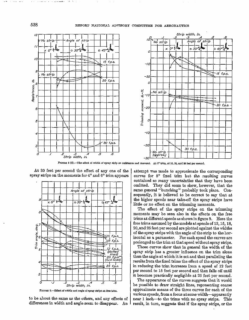
FIGURE8 (d).-The effd of width of spray strip cmmsfstancaand momant. At P ~ at 16,23,and 30fed par semnd.
At 30 feet per second the effect of any one of thespray strips on the moments for 4° and 6° trim appema
.9
8
67
%*’b6c
.;~5
4
3
0 --l .2 .3 .4 .5 .6S7%@ wio’fh, in.
to be about the same as the others, and any effects ofdiflerencea in width and angle seem to disappear. An
attempt was made to approximate the correspondingcm-ma for 8° tied trim but the resulting cmrveacontsined so many uncertainties that they have beenomitted. They did seem to show, however, that thesame general “bunching” probably took place. Con-sequently, it is believed to be correct to my that atthe higher speeds near take-off the spray strips havelittle or no effect on the tirimmiqg moments.
The tiect of the spray strips on the trimmingmoments may be seen also in the effects on the freetrims at diilerent speeds as shown in figure 9. Here thefree trims aasumedby the models at speeds of 12,15, 18,20, and 25 feet per second are plotted against the widthsof the spray strips with the angle of the strip to the hor-izontal as a parameter. For each speed the curves areprolongedtc the trim at that speed without spray strips.
These curves show that in general the width of thospray strip has a greater influence on the trim alonethan the angle at which it is set and that paralleling theresults from the tied trims the effect of the spray stripsin reducing the trim increases from a speed of 12 feetper second to 15 feet per second and then falls ofl untilit becomes practically negligible at 25 feet per second,
The appemce of the curves suggests that it wouldbe possible to draw straight lines, representing coarseapproximate means of the three curves for each of thovarious speeds, from a focus at some width-apparentlynear 1 inch-to the trims with no spray strips. Thisresult, in turn, suggests that if the spray strips, or the

lWFECP OF SPRAY STRIPS ON ‘PAKJ+O~ PERFORMANCEOF A MODEL OF A FLYJ-NQ-BOATHULL 539
deflecting planes of the bottom, were made about 1 inchwide, or about 6 percent of the beam, the model mightbe found not to change trim between 12 and 25 feet persecond and might travel at a constant trim of about 3°for the whole of the take-off run. The possibility willbe investigated of making a model hold a constanttrim, of itself, through the take+ff run by fitting a.suitable spray strip. It is understood that thephenomenon has been observed in tests in otherhulks.
From the foregoing it follows that the addition ofthe spray strip, especially at the greater widths andlarger angles, will tend to reduce the positive trimmingmoments during the earlier stages of a take-off and, inparticular, should reduca the speed that must bereached before the aerodynamic controls of a flyingboat can become effective in controlling attitude.
CONCLUSIONS
The conclusions drawn from this series of tests are,of course, strictly applicable only to the model testedand mtthe load and speeds used. They should applyquite well, however, to hulls of genenilly similar formoperated at lords and speeds that give approximatelythe snmeload and speed coefficients.1
Spray,—There appears to be no criterion for effi-ciency in suppressing the spray. Opinion based uponobswvation must serve for the present. It is believedthat spray strips having a width of horn 2 to 3 percentof the beam and set at angles of from 30° to 45° belowthe horizontal at the step give the best reduction inthe spray from the condition found with no spraystrip. Apparently the width might be increased withimproved suppression, but supporting the strips wouldbecome a problem.
Based upon observation durhg these tests it isbelieved that spray strips generally should extendfarther forward than those tested on this model—iffeasible, right mound the bow—and that the down-ward angles near the bow should be not 1sss iihanthose corresponding to those used with the 45° setting.
Rise.—The effect of spray strips on the rise probablymay be neglected, although it is real and can be ob-served in the model tests.
IThssa coellfclante,wftb the rdstanm and trfmmfng-moment cmfffdentsj erodoflnecfos
I/red coefllofent CA- *
Sped cmfflotentc“&
RosfEbmcamaflfdontc’-%%
Trlnmdog-moment -mOhd CM-*
where A, lcmdon the wok, lb. (or kg)~ water rdstanc% lb. (or kg)W, wotgbt demfty of water, lb. w CU.ft. (or @.hn $)
(l% tbe NAO.A. Tank w- 53.6lb. w on.ft.)b,bmm of bullj ft. (orm )
M, Mmrnfng momon~ lb.-ft. (or kg-m)v, .9-, k fmr 532. (or m/s)g, acmfmatfon of gravfty, fk per sm.t (or m/e9
Resistance.—The general effect of the spray strips isto reduce the resistance at speeds below and at thehump. In free-to-trim runs the addition of the spraystrips causes the model to trim lower and rise a littlemore. The combined effect is a reduction in resistance.In iixed-trim runs the trim is maintained but a smallermoment is required to hold the trim while the rise isincreased. The combined effect again is a reductionin resistance. At higher speeds, and especially nearthe get-away speed, the resistance is either about thesame as without the spray strips or is slightly in-creased. The wider strips (2.25 to 3 percent of thebemn) at 30° to 45° downward angle give more reduc-tion in resistsmce at the lower speeds and cause nomore rwistsmce than the narrower strips at any angle.At speeds near get-away the resistance at the lowtrim angles (4° to 6°) is affected only slightly by fittingthe wider strips at the greater angles.
Moments.—At speeds in the neighborhood of thehump the addition of spray strips introduces a con-sistent negative trimmm“ g moment. The wider (2.25to 3 percent of beam) and steeper (30° and 46°) spraystrips produce a greatar effect at the lower speeds.The reduction in the positive trindng moment thusobtained should make the aerodynamic controls be-come effective earlier in the take-off run.
At speeds near the get-away the change producedby adding the spray strips is relatively slight. Theeffectiveness of the aerodynamic control of the fuU-size craft should not be disturbed by the small increasein the negative value of the moments.
LANGLEY MEMORIAL AERONAUTICAL LABORATORY,NATIONAL ADVISORY COMWITE E FOR AERONAUTICS,
LANGLEY FIELD, JTA., June 16, 1934.
REFERENCES
1. Richardson, Holden C.: Aircraft Float Design. The RonaldPm co., 1928.
2. Lucking, D. F.: The Design of Marine Airoraft in Relationto %mvorthinws. Jour. Roy. Aero. Soo., Novemkmr 1923,pp. 53S-552.
3. Baker, G. S. and Bottoraley, G. H.: Esperimenta withModels of t%aplane Floats (Eighth Series). R- & M. No.187, British A. C.A., 1915.
4. William Froude National Tank StaiT and Grigg, A. D.: Ex-periments with Models of Seaplane Floats (Ninth Series).IL & M. No. 188, Britioh A. C.A., 1916.
5. Baker, G. S. and Keary, E. M.: Experiments with Models ofSeaplane Floats (Tenth Serkj. 1?- & M. No. 189,British A. C.A., 1916.
6. Truscott, Starr: The N.A.C.A. Tank-A High43peed Tow-ing Basin for Testing Models of Seaplane Floati T. IL .No. 470, N. A. C.A., 1933.
7. Sottorf, W.: Experiments with Planing Surfacea. T. M.No. 739, N. A. C.A., 1934.


![[XLS]test.nhb.org.intest.nhb.org.in/Urban_Housing/4041 statutory Towns.xlsx · Web view502 802681 27 502 802682 27 503 802683 27 503 802684 27 503 802685 27 503 802686 27 503 802687](https://static.fdocuments.us/doc/165x107/5ab1742b7f8b9abc2f8cb599/xlstestnhborg-statutory-townsxlsxweb-view502-802681-27-502-802682-27-503-802683.jpg)

