Report C: AIPOLY 5.0 The Plant · 5 Total Dissolved Solids 150 – 700 mg/l NA* 69 mg/l 3025 : 1984...
40
Detailed Feasibility Report on Mineral Water Project – Bhutan Report C: AIPOLY 61 The plant for the project is located close to the source and sized for the most efficient utilization of the spring’s water flow rate. It is designed to carry out the physical processes only of water treatment, carbonating and bottling, as prescribed by the European Codex Alimentarus and the Indian Standard IS 14543:2004. Due care has been taken to select equipment from reputable manufacturers and preference given to those manufacturers who have already supplied equipment to Bhutan. The selection has also been influenced by the ability of the manufacturers to coordinate with each other and by their commitment to install and prove their equipment on site, as well as train the local staff in the proper operation and maintenance of their equipment. Water samples taken from this spring source in Aipoly were handed in to a Laboratory duly accredited by the Ministry of Environment and Forest of the Government of India, for testing to IS 13428:2005. The report of this Laboratory, (TEAM Institute of Science & Technology Pvt. Ltd., Lab G1-584 Sitapura Industrial Area Jaipur 302022- India), Report No. 347 dated 9 th March, 2007 is reproduced in Appendix III. It shows that the water has a TDS content of 69 mg/litre, but it is noted that in the ‘table 2 General Parameters Concerning Substances Undesirable in Excessive Amounts’, the turbidity (3 NTU) is found to be in excess over the 2 NTU maximum prescribed. This will require the introduction of a special filter to reduce the turbidity without affecting the TDS. The site of the plant at Latitude 26 o 55’ 15” N and Longitude 90 o 27’ 12” E, is shown in Toposheet No.78 E/11 (Survey of Bhutan) reproduced in chapter 6.0. The bottling of water represents an activity in which the basic raw material has to be of the right quality, and the value addition is in terms of physical treatments for ensuring against pathogenic micro-organisms, and in the proper packaging. The project technical concept is dictated by these requirements. This is a clean technology producing little waste or by product. The process details are given in section 5.2 onwards. Process technology aspects describe the key considerations and options vis-à-vis the selection of the most suitable process for the project, plant capacity and size. The manufacturing process details, the type of main & auxiliary machinery, storage, design of various systems, a suggested plant layout and a process flow sheet. 5.1 Choice of Technology The plant technical concept is based upon treatment and bottling processes to deliver a final product fully in line with requirements of Packaged Natural Mineral Water. All the standards viz. European, Indian and US, mandate that the processes be • Carried out under hygienic conditions • Maintain the original mineral composition of the water Plant and machinery quotations were invited from leading Indian mineral water plant manufacturers based on the test report. The technology from world leader in Mineral Water Plant design and manufacturing M/s CESI Consultant International WEDECO KATADYN, France, was also referred. Comparison indicated that price of the French technology was substantially higher. The quotations received from three main Indian suppliers were analyzed on techno-economical considerations and the best was selected for inclusion in this feasibility report. The list of the water treatment plant manufacturers is given in Appendix V (d). The Indian technology was found best for this project based on following considerations: (i) The technology and filtration process compliance to all the three standards viz. European, Indian and US (ii) Lower capital cost (iii) Lower running and maintenance cost (iv) Operational suitability for adoption to local environment (v) Easy availability of spare parts at lower costs 5.0 The Plant
Transcript of Report C: AIPOLY 5.0 The Plant · 5 Total Dissolved Solids 150 – 700 mg/l NA* 69 mg/l 3025 : 1984...

Detailed Feasibility Report on Mineral Water Project – Bhutan Report C: AIPOLY
61
The plant for the project is located close to the source and sized for the most efficient utilization of the
spring’s water flow rate. It is designed to carry out the physical processes only of water treatment, carbonating and bottling, as prescribed by the European Codex Alimentarus and the Indian Standard IS 14543:2004. Due care has been taken to select equipment from reputable manufacturers and preference given to those manufacturers who have already supplied equipment to Bhutan. The selection has also been influenced by the ability of the manufacturers to coordinate with each other and by their commitment to install and prove their equipment on site, as well as train the local staff in the proper operation and maintenance of their equipment. Water samples taken from this spring source in Aipoly were handed in to a Laboratory duly accredited by the Ministry of Environment and Forest of the Government of India, for testing to IS 13428:2005. The report of this Laboratory, (TEAM Institute of Science & Technology Pvt. Ltd., Lab G1-584 Sitapura Industrial Area Jaipur 302022- India), Report No. 347 dated 9th March, 2007 is reproduced in Appendix III. It shows that the water has a TDS content of 69 mg/litre, but it is noted that in the ‘table 2 General Parameters Concerning Substances Undesirable in Excessive Amounts’, the turbidity (3 NTU) is found to be in excess over the 2 NTU maximum prescribed. This will require the introduction of a special filter to reduce the turbidity without affecting the TDS. The site of the plant at Latitude 26o 55’ 15” N and Longitude 90o 27’ 12” E, is shown in Toposheet No.78 E/11 (Survey of Bhutan) reproduced in chapter 6.0. The bottling of water represents an activity in which the basic raw material has to be of the right quality, and the value addition is in terms of physical treatments for ensuring against pathogenic micro-organisms, and in the proper packaging. The project technical concept is dictated by these requirements. This is a clean technology producing little waste or by product. The process details are given in section 5.2 onwards. Process technology aspects describe the key considerations and options vis-à-vis the selection of the most suitable process for the project, plant capacity and size. The manufacturing process details, the type of main & auxiliary machinery, storage, design of various systems, a suggested plant layout and a process flow sheet.
5.1 Choice of Technology The plant technical concept is based upon treatment and bottling processes to deliver a final product fully in line with requirements of Packaged Natural Mineral Water. All the standards viz. European, Indian and US, mandate that the processes be
• Carried out under hygienic conditions • Maintain the original mineral composition of the water
Plant and machinery quotations were invited from leading Indian mineral water plant manufacturers based on the test report. The technology from world leader in Mineral Water Plant design and manufacturing M/s CESI Consultant International WEDECO KATADYN, France, was also referred. Comparison indicated that price of the French technology was substantially higher.
The quotations received from three main Indian suppliers were analyzed on techno-economical considerations and the best was selected for inclusion in this feasibility report. The list of the water treatment plant manufacturers is given in Appendix V (d).
The Indian technology was found best for this project based on following considerations: (i) The technology and filtration process compliance to all the three standards viz. European, Indian and
US (ii) Lower capital cost (iii) Lower running and maintenance cost (iv) Operational suitability for adoption to local environment (v) Easy availability of spare parts at lower costs
5.0 The Plant
Detailed Feasibility Report on Mineral Water Project – Bhutan Report C: AIPOLY
62
5.1.1 Collection of Water The Standard requires that the source be sealed from ingress of surface water. Further it requires that the water be handled only in permissible materials and not be transported by tanker, but bottled as close to the source as possible. Sealing requires isolating the source completely from the surrounding ground conditions. Carriage of the water will have to be done through stainless steel or HDPE pipes. Further the perimeter around the source and upstream of it has to be protected from ingress of human or bovine populations, by fencing it. 5.1.2 Treatment of Water The treatment processes specified under these standards do not permit any chemical intervention for modification of any of the essential constituents – by either removal or fortification. The processes selected therefore are of filtration and disinfection before bottling. These processes must not affect the various characteristics of the water as specified in various tables in the Standard IS 13428:2005. Due to the requirement in the Indian Standard of the TDS to be a minimum of 150 mg/l, this water does not qualify for certification under the Indian Standard, but it is taken as a reference since other parameters are exactly as per the European Codex. Both the standards are reproduced in part in Appendix II, for reference purposes only. The headings under, which water quality is specified are given below: “Requirements for biological contaminants Table 1: Organoleptic and Physical Parameters Table 2: General Parameters Concerning Substances Undesirable in Excessive Amounts Table 3: Parameters Concerning Toxic Substances Table 4: Parameters Concerning Radio-active Residues” 5.1.3 Biological Requirements Absence of various strains of bacteria is specified under this head. These are coliform, thermotolerant, faecal streptococci, staphylococcus aureus, sulphite reducing anaerobes, psuedomonas aeruginosa, yeast and mould, salmonella, shigella, fibriocholera, and V. parahaemolyticus.
S. No.
Characteristics Requirements (IS 13428:2005)
Aipoly Water Test Result
Method of Test (Reference to Indian Standards)
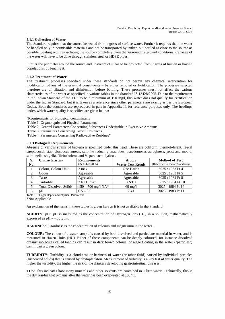
1 Colour, Colour Unit 2 max One Hazen 3025 : 1983 Pt 4 2 Odour Agreeable Agreeable 3025 : 1983 Pt 5 3 Taste Agreeable Agreeable 3025 : 1984 Pt 8 4 Turbidity 2 NTU max 3 NTU 3025 : 1984 Pt 10 5 Total Dissolved Solids 150 – 700 mg/l NA* 69 mg/l 3025 : 1984 Pt 16 6 pH 6.5 – 8.5 7.41 3025 : 1983 Pt 11
Table 5.1: Organoleptic and Physical Parameters *Not Applicable An explanation of the terms in these tables is given here as it is not available in the Standard. ACIDITY: pH: pH is measured as the concentration of Hydrogen ions (H+) in a solution, mathematically expressed as pH = -log10 α H+. HARDNESS : Hardness is the concentration of calcium and magnesium in the water. COLOUR: The colour of a water sample is caused by both dissolved and particulate material in water, and is measured in Hazen Units (HU). Either of these components can be deeply coloured, for instance dissolved organic molecules called tannins can result in dark brown colours, or algae floating in the water ("particles") can impart a green colour.
TURBIDITY: Turbidity is a cloudiness or haziness of water (or other fluid) caused by individual particles (suspended solids) that is caused by phytoplankton. Measurement of turbidity is a key test of water quality. The higher the turbidity, the higher the risk of the drinkers developing gastrointestinal diseases. TDS: This indicates how many minerals and other solvents are contained in 1 litre water. Technically, this is the dry residue that remains after the water has been evaporated at 180 oC.

Detailed Feasibility Report on Mineral Water Project – Bhutan Report C: AIPOLY
63
This table lists the permissible maximum values of minerals in the water and also gives the test results of actual sample water collected at Aipoly. (Report no. 347 given in Appendix III)
S. No. Characteristics Requirements mg/l max
(IS 13428:2005)
Aipoly Water Test Result
mg/l max
Method of Test (Reference to Indian Standards)
1 Nitrate (as NO3) 50 0.86 IS 3025 : 1988 Pt 34
2 Nitrite (as NO2) 0.02 Nil IS 3025 : 1988 Pt 34
3 Hydrogen Sulphide (as H2S) 0.05
Nil IS 3025 : 1986 Pt 29
4 Manganese (as Mn) 2.0 Nil 35 of IS 3025 : 1988 5 Copper (as Cu) 1.0 Nil IS 3025 : 1992 Pt 42
6 Zinc (as Zn) 5 Nil IS 3025 : 1994 Pt 49
7 Fluoride (as F) 2.0 0.2 23 of IS 3025 : 1964
8 Barium (as Ba) 1.0 Nil 13428 : 2005 Annex F
9 Antimony (as Sb) 0.005 Nil 13428 : 2005 Annex G
10 Borate (as B) 5 Nil 13428 : 2005 Annex H
11 Silver (as Ag) 0.01 Nil 13428 : 2005 Annex J
12 Chloride (as Cl) 200 7.1 IS 3025 : 1988 Pt 32
13 Sulphate (as SO4) 200 21.56 IS 3025 : 1986 Pt 24
14 Magnesium (as Mg) 50 16.8 IS 3025 : 1994 Pt 46
15 Calcium (as Ca) 100 12 IS 3025 : 1991 Pt 40
16 Sodium (as Na) 150 0.35 IS 3025 : 1993 Pt 45 17 Alkalinity (as HCO3) 75 to 400 20 IS 3025 : 1986 Pt 23
18 Iron 0.3 0.2090 IS 3025 : 1986 Pt 23
19 Selenium (as Se) 0.05 Nil 28 of IS 3025 : 1964 Table 5.2: General Parameters Concerning Substances Undesirable in Excessive Amounts
This table lists the maximum permissible values of toxic substances.
S. No. Characteristics Requirements mg/l max
(IS 13428:2005)
Demola Water Test Result
mg/l max
Method of Test (Reference to Indian Standards)
1 Arsenic (as As) 0.05 Nil 3025 : 1988 Pt 37 2 Cadmium (as Cd) 0.0003 Nil 3025 : 1992 Pt 41
3 Cyanide (as CN) 0.07 Nil 3025 : 1986 Pt 27
4 Chromium (as Cr) 0.05 Nil 13428 : 2005 Annex J
5 Mercury (as Hg) 0.001 Nil 3025 : 1994 Pt 48
6 Lead (as Pb) 0.01 Nil 3025 : 1994 Pt 47
7 Nickel (as Ni) 0.02 Nil 13428 : 2005 Annex L Table 5.3: Toxic Substances Although it is not applicable to any site in Bhutan. However, in the standards radioactive residue parameters are specified. (Only for reference).
S. No. Characteristics Requirements mg/l max
(IS 13428:2005)
Method of Test (Reference to Indian Standards)
1 Alpha Emitters 0.1 Bq/l max 14194 : 1994 Pt 2
2 Beta Emitters 1 PCi/l max 14194 : 1994 Pt 1 Bq : becquerel 1 = 1 disintegration per second PCi : pico Curie 1 = 2.22 disintegration per second Table 5.4: Radioactive Residue Parameters

Detailed Feasibility Report on Mineral Water Project – Bhutan Report C: AIPOLY
64
5.1.4 Packaging of Water Water must not only be of the specified quality to start with, it must also be handled in permissible materials. The containers and conduits for water must conform to the following specifications: Standard Title IS 15410 : 2003 Containers for Packaging of Natural Mineral Water and Packaged Drinking Water –
Specification IS 2798 : 1998 Methods of test for plastics containers IS 4905 : 1968 Methods for random sampling IS 7019 : 1998 Glossary of terms in plastics and flexible packaging excluding paper IS 8747 : 1977 Methods of test for environmental stress-crack resistance of blow-moulded polyethylene
containers IS 9845 : 1998 Determination of overall migration of constituents of plastics materials and articles
intended to come in contact with foodstuffs - Method of analysis IS 12252 : 1987 Polyalkylene terephthalates (PET and PBT) for their safe use in contact with foodstuffs,
pharmaceuticals and drinking water IS 4984:1995 Specification for High Density Polyethylene pipes for potable water supplier
Table 5.5: Standards for Quality of Packaging Materials
The Standard specifies that the packaged water be marked with the following: 1. Name of the product 2. Name and address of the producer 3. Brand name, if any 4. Net volume 5. Location and name of source of the mineral water 6. Directions for storage 7. Batch or code number 8. Date of processing 9. ‘Best for Consumption’ date
The Standard specifies the hygienic conditions under, which the water must be packaged, and this is taken into account in designing the plant and process described later in this chapter.
5.2 Alternate Technologies
5.2.1 Collection of Water The alternate technologies for the collection of water are:
1. Collecting the water as it comes naturally out of the ground 2. Drilling down to the aquifer and pumping the water out
The second option becomes viable only when there are large proven reserves of water. The hydrological survey to be conducted in the preliminary stage will reveal more about the proven reserves of the aquifer, but at this stage, it is proposed to collect the available flow only. However, to prevent any contamination from surface water, it is recommended to drill the spring source up to 10 ft depth and insert a stainless steel pipe into it. This pipe is connected to the pipe carrying the water to the plant, through a fabricated stainless steel manifold, which has a provision for the outlet pipe connection, and a tapping point from where samples can be collected. The area around the pipe entry to the ground is to be enclosed by a room so as to prevent unauthorized access.
5.2.2 Water Treatment If there are major chemical deviations from the standard, the water cannot be packaged as Natural Mineral Water, since chemical interventions that might alter the original composition of the water, are not permitted. This excludes fortification of the mineral content. The various technologies for the processes of Filtration and Disinfection are given below (see also section 5.4.2.2):
• Removal of suspended particles & turbidity. • Removal of undesirable odour and taste. • Improvement of clarity through Water Polisher and Absolute Filtration. • Reduction in turbidity through Nano Ceram filter • Disinfection through Ultra Violet radiation.

Detailed Feasibility Report on Mineral Water Project – Bhutan Report C: AIPOLY
65
• Removal of macromolecules such as colloids, proteins, glycols, microbiological contaminants and large organic molecules through Ultra Filtration.
• Ozone Treatment for total disinfection.
The technologies mentioned above do not alter the original composition of the water except removing the bacterial impurities, suspended particles and undesired or excessive elements.
The equipment for carrying out these processes is shown in the table below:
S. No. Technology Equipment 1 Removal of suspended particles & turbidity Sand Filter, NanoCeram filter 2 Removal of undesirable odour and taste Activated Carbon Filter 3 Improvement of clarity through Water polisher Water Polisher 4 Absolute Filtration Micron Filter 5 Disinfection
Ultraviolet Radiation Ozonator
6 Bottling and Carbonation Automatic Rinser, Filler, Capper 7 Packaging Sealer & Shrink Wrapper 8 Manufacture of PET Bottles Injection Moulding of Preform
Blowing of PET Bottle Table 5.6: Selection of Equipment
Since the water has no odour and tastes well, processing through carbon filters is not required. The NanoCeram filter is made by Argonide Corporation, 291 Power Court, Sanford, FL 32771, USA, with a special technology using nano size fibres.
5.2.3 Packaging of Water The alternate technologies relate only to the selection of the container, which could be made of:
a. PET Bottle b. Glass Bottle c. Paper Carton
a. PET Bottle It is seen that the PET bottle is the most universally accepted container for drinking water for the following reasons:
1. It is transparent - everyone wants to see that the water being drunk is clean and clear. 2. It is easy to manufacture. 3. It has a low cost. 4. It is disposable. 5. It ensures that water being bottled is always in a new and freshly made bottle. 6. It is light, can be transported easily, and is ideally suited for air transport worldwide.
b. Glass Bottle Glass bottles are expensive in first cost and are suitable only where recycling is possible. There is a heavy cost in recycling due to transportation and breakage losses. The bottle rinsing process is expensive and non eco-friendly. Certain European and Russian natural mineral waters are bottled in glass, when their supposedly healing effects obtain premium prices for them. Glass bottles are rejected for this project.
c. Paper Carton Paper has the main disadvantage of lack of transparency coupled with low strength for a comparable cost, and paper is universally rejected as an option. As for marking, the options are of printing directly on the bottle versus printing on a label, which is made so as to make removal impossible for the life of the product. Both options are unviable in themselves, and a sensible mean is drawn in which all the standard information is printed on a heat shrinkable label and the batch numbers, processing date and ‘Best Use Before’ date are printed directly on the bottle with an automatic inkjet printer.
Detailed Feasibility Report on Mineral Water Project – Bhutan Report C: AIPOLY
66
5.2.4 Selected Manufacturing Process
A. Collection • Drilling the source to obtain optimum constant flow • Inserting stainless steel collecting pipes with primary filters • Sealing the pipes from external draws • Providing collection points (and pumping arrangements if necessary) • Providing against tampering with the source, collection and transportation facilities
B. Filtration • Designing an appropriate series of filters based on the quality of the water • Determining intermediate storages • Designing micron filtration
C. Bottle Making • Injection Moulding for PET Preforms • Blowing of PET Bottles
D. Bottle Filling • Bottle Pre-washing or Rinsing • Bottle Filling • Carbonation • Capping • Bottle Marking, Labeling and Packaging
5.3 Broad Capacity Sizing The capacity of the plant is determined by the flow of water available. At the site of the spring at Aipoly, the flow is estimated at about 60 litres per minute. When the water is bottled, the bottles are to be pre-washed before filling, and this will consume some part of the water. Therefore, the actual available water for bottling is considered to be 50 litres per minute. The basic plant and machinery capacity is planned on the modular concept of 50 nos.1,000 ml bottles per minute. The equipment is to be capable of accepting size changeovers in the following capacities: 200 ml, 500 ml, 1,000 ml and 2,000 ml.
5.4 Design Concept The plant is designed on the basis of the water from the spring being pure and flowing constantly at the rate of 60 litres per minute. The design concept is required for the volume of water, the processes through which the water is to be treated and for the packaging of the product. Each aspect of design is detailed. 5.4.1 Plant Design Parameters The plant design parameters are dictated by the volume of water available for bottling. In the case of this site at Aipoly, the volume of water available is 60 litres per minute. The plant is designed for operation in 3 shifts, but will be run in 2 shifts initially looking to the availability and convenience of staff, as well as development of the market. The design parameters are described below:
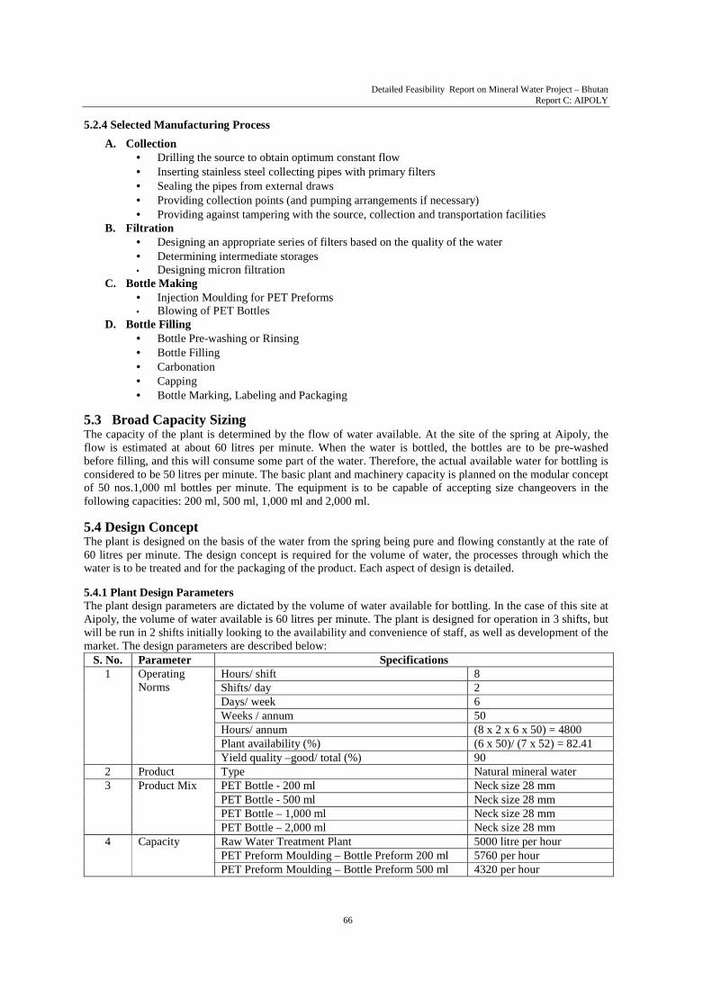
S. No. Parameter Specifications 1 Operating
Norms Hours/ shift 8 Shifts/ day 2 Days/ week 6 Weeks / annum 50 Hours/ annum (8 x 2 x 6 x 50) = 4800 Plant availability (%) (6 x 50)/ (7 x 52) = 82.41 Yield quality –good/ total (%) 90
2 Product Type Natural mineral water 3 Product Mix PET Bottle - 200 ml Neck size 28 mm
PET Bottle - 500 ml Neck size 28 mm PET Bottle – 1,000 ml Neck size 28 mm PET Bottle – 2,000 ml Neck size 28 mm
4 Capacity Raw Water Treatment Plant 5000 litre per hour PET Preform Moulding – Bottle Preform 200 ml 5760 per hour PET Preform Moulding – Bottle Preform 500 ml 4320 per hour
Detailed Feasibility Report on Mineral Water Project – Bhutan Report C: AIPOLY
67
S. No. Parameter Specifications PET Preform Moulding – Bottle Preform 1,000 ml 3600 per hour PET Preform Moulding – Bottle Preform 2,000 ml 2880 per hour PET Blowing – 200 ml Bottles 4000 per hour PET Blowing – 500 ml Bottles 3350 per hour PET Blowing – 1,000 ml Bottles 3000 per hour PET Blowing – 2,000 ml Bottles 2600 per hour Filling and Packaging capacity to match blowing capacities
Table 5.7: Plant Design Parameters
5.4.2 Process Design Parameters
The following factors in water composition are to be taken into account for the System Design: 1. Absence of physical and chemical constituents in excess of those permitted by the standard 2. Absence of biological contamination
5.4.2.1 Physical and Chemical Constituents a. The chemical constituents of the water have been tested and found to be within the prescribed limits.
However, further testing will be required, as follows :
• Collection of samples by averaging methods • Testing by a certified Toxicology Laboratory (e.g. at the Industrial Toxicological Research
Institute, Lucknow, India) for detection of all the parameters described above. b. For the physical parameters, it is necessary to incorporate suitable filtration methods to ensure removal of
foreign particles at the micron level. c. Materials of construction of all the processing equipment throughout the processing of the product will
be as permitted by the Standard.
S. No. Parameter Specifications 1 Mineral Water General
Characteristics Colour, Colour Unit IS 3025 : 1983 Pt 4 2 max Odour IS 3025 : 1983 Pt 5 Agreeable Taste IS 3025 : 1984 Pt 8 Agreeable pH IS 3025 : 1983 Pt 11 6.5 – 8.5
2 Chemical Parameters Nitrate (as NO3), IS 3025 : 1988 Pt 34 50 Mg/l Nitrite (as NO2) IS 3025 : 1988 Pt 34 0.02 Mg/l Sulphide (as H2S) IS 3025 : 1986 Pt 29 0.05 Mg/l Manganese (as Mn) 35 of IS 3025 : 1988 2.0 Mg/l Copper (as Cu) IS 3025 : 1992 Pt 42 1.0 Mg/l Zinc (as Zn) IS 3025 : 1994 Pt 49 5 Mg/l Fluoride (as F) 23 of IS 3025 : 1964 2.0 Mg/l Barium (as Ba) 13428 : 2005 Annex F 1.0 Mg/l Antimony (as Sb) 13428 : 2005 Annex G 0.005 Mg/l Borate (as B) 13428 : 2005 Annex H 5 Mg/l Silver (as Ag) 13428 : 2005 Annex J 0.01 Mg/l Chloride (as Cl) IS 3025 : 1988 Pt 32 200 Mg/l Sulphate (as SO4) IS 3025 : 1986 Pt 24 200 Mg/l Magnesium (as Mg) IS 3025 : 1994 Pt 46 50 Mg/l Calcium (as Ca) IS 3025 : 1991 Pt 40 100 Mg/l Sodium (as Na) IS 3025 : 1993 Pt 45 150 Mg/l Alkalinity (as HCO3) IS 3025 : 1986 Pt 23 75 to 400 Selenium (as Se) 28 of IS 3025 : 1964 0.05 Mg/l Mineral Oil IS 3025 : 1991 Pt 39 Not Detectable Phenolic compounds (as C6H3OH) 54 of IS 3025 : 1964
Not Detectable
Anionic surface active agent 13428 : 2005 Annex K Not Detectable 3 Physical Parameters Turbidity IS 3025 : 1984 Pt 10 2 NTU max
Total Dissolved Solids IS 3025 : 1984 Pt 16 150 – 700 mg/l 4 Biological Parameters As specified (see Excerpts from the Standard in
Detailed Feasibility Report on Mineral Water Project – Bhutan Report C: AIPOLY
68
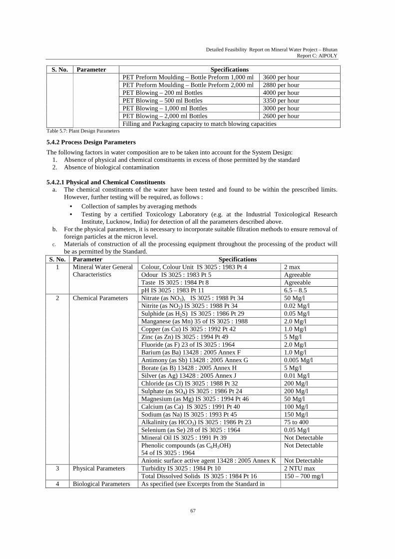
S. No. Parameter Specifications 5 Toxic Substance
Parameters Arsenic (as As) IS 3025: 1988 Pt 37 0.05 Mg/l Cadmium (as Cd) IS 3025: 1992 Pt 41 0.0003 Mg/l Cyanide (as CN) IS 3025: 1986 Pt 27 0.07 Mg/l Chromium (as Cr) IS 13428: 2005 Annex J 0.05 Mg/l Mercury (as Hg) IS 3025: 1994 Pt 48 0.001 Mg/l Lead (as Pb) IS 3025: 1994 Pt 47 0.01 Mg/l Nickel (as Ni) 13428: 2005 Annex L 0.02 Mg/l Polychlorinated Biphenyl (PCB) IS 13428: 2005 Annex M
Not Detectable
Polynuclear Aromatic Hydrocarbons Test method not yet finalized
Not Detectable
6 Radioactive Residue Parameters
Alpha Emitters 14194: 1994 Pt 2 0.1 Bq/l max Beta Emitters 14194: 1994 Pt 1 1 pCi/l max
Table 5.8: System Design Parameters
Should it be required, a ‘Nano Ceram’ (manufactured by Argonide Corporation, 291 Power Court, Sanford, FL 32771, USA (www.argonide.com) filter may be installed to reduce turbidity.
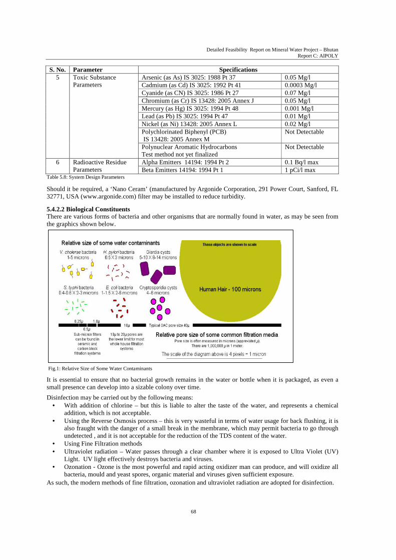
5.4.2.2 Biological Constituents There are various forms of bacteria and other organisms that are normally found in water, as may be seen from the graphics shown below.
Fig.1: Relative Size of Some Water Contaminants
It is essential to ensure that no bacterial growth remains in the water or bottle when it is packaged, as even a small presence can develop into a sizable colony over time.
Disinfection may be carried out by the following means: • With addition of chlorine – but this is liable to alter the taste of the water, and represents a chemical
addition, which is not acceptable. • Using the Reverse Osmosis process – this is very wasteful in terms of water usage for back flushing, it is
also fraught with the danger of a small break in the membrane, which may permit bacteria to go through undetected , and it is not acceptable for the reduction of the TDS content of the water.
• Using Fine Filtration methods • Ultraviolet radiation – Water passes through a clear chamber where it is exposed to Ultra Violet (UV)
Light. UV light effectively destroys bacteria and viruses. • Ozonation - Ozone is the most powerful and rapid acting oxidizer man can produce, and will oxidize all
bacteria, mould and yeast spores, organic material and viruses given sufficient exposure.
As such, the modern methods of fine filtration, ozonation and ultraviolet radiation are adopted for disinfection.
Detailed Feasibility Report on Mineral Water Project – Bhutan Report C: AIPOLY
69
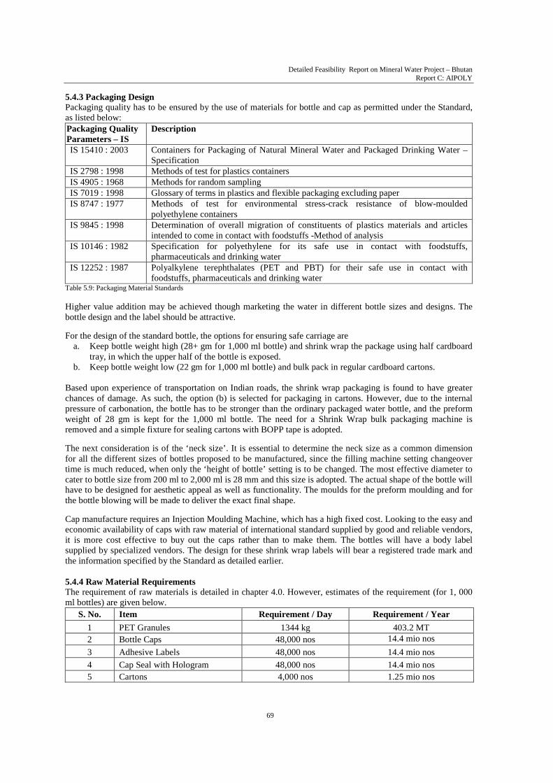
5.4.3 Packaging Design Packaging quality has to be ensured by the use of materials for bottle and cap as permitted under the Standard, as listed below:
Packaging Quality Parameters – IS
Description
IS 15410 : 2003 Containers for Packaging of Natural Mineral Water and Packaged Drinking Water – Specification
IS 2798 : 1998 Methods of test for plastics containers IS 4905 : 1968 Methods for random sampling IS 7019 : 1998 Glossary of terms in plastics and flexible packaging excluding paper IS 8747 : 1977 Methods of test for environmental stress-crack resistance of blow-moulded
polyethylene containers IS 9845 : 1998 Determination of overall migration of constituents of plastics materials and articles
intended to come in contact with foodstuffs -Method of analysis IS 10146 : 1982 Specification for polyethylene for its safe use in contact with foodstuffs,
pharmaceuticals and drinking water IS 12252 : 1987 Polyalkylene terephthalates (PET and PBT) for their safe use in contact with
foodstuffs, pharmaceuticals and drinking water Table 5.9: Packaging Material Standards Higher value addition may be achieved though marketing the water in different bottle sizes and designs. The bottle design and the label should be attractive. For the design of the standard bottle, the options for ensuring safe carriage are
a. Keep bottle weight high (28+ gm for 1,000 ml bottle) and shrink wrap the package using half cardboard tray, in which the upper half of the bottle is exposed.
b. Keep bottle weight low (22 gm for 1,000 ml bottle) and bulk pack in regular cardboard cartons.
Based upon experience of transportation on Indian roads, the shrink wrap packaging is found to have greater chances of damage. As such, the option (b) is selected for packaging in cartons. However, due to the internal pressure of carbonation, the bottle has to be stronger than the ordinary packaged water bottle, and the preform weight of 28 gm is kept for the 1,000 ml bottle. The need for a Shrink Wrap bulk packaging machine is removed and a simple fixture for sealing cartons with BOPP tape is adopted. The next consideration is of the ‘neck size’. It is essential to determine the neck size as a common dimension for all the different sizes of bottles proposed to be manufactured, since the filling machine setting changeover time is much reduced, when only the ‘height of bottle’ setting is to be changed. The most effective diameter to cater to bottle size from 200 ml to 2,000 ml is 28 mm and this size is adopted. The actual shape of the bottle will have to be designed for aesthetic appeal as well as functionality. The moulds for the preform moulding and for the bottle blowing will be made to deliver the exact final shape. Cap manufacture requires an Injection Moulding Machine, which has a high fixed cost. Looking to the easy and economic availability of caps with raw material of international standard supplied by good and reliable vendors, it is more cost effective to buy out the caps rather than to make them. The bottles will have a body label supplied by specialized vendors. The design for these shrink wrap labels will bear a registered trade mark and the information specified by the Standard as detailed earlier. 5.4.4 Raw Material Requirements The requirement of raw materials is detailed in chapter 4.0. However, estimates of the requirement (for 1, 000 ml bottles) are given below.
S. No. Item Requirement / Day Requirement / Year
1 PET Granules 1344 kg 403.2 MT 2 Bottle Caps 48,000 nos 14.4 mio nos
3 Adhesive Labels 48,000 nos 14.4 mio nos
4 Cap Seal with Hologram 48,000 nos 14.4 mio nos 5 Cartons 4,000 nos 1.25 mio nos

Detailed Feasibility Report on Mineral Water Project – Bhutan Report C: AIPOLY
70
Letter Area Description
A Source Feed Area
B Raw Water Storage Area
C Raw Water Treatment Plant
D Bottling Blowing Plant Area
E Rinsing, Filling, Capping Area
F Raw Material Storage Area
G Finish Goods Storage Area
H Services Area Table 5.11: Legend on Plant Layout
S. No. Item Requirement / Day Requirement / Year
6 BOPP Tape 4,000 m 1,200,000 m
7 Food grade CO2 0.24 MT 72 MT
8 Bottle Printing Ink (food grade) 8 litres Table 5.10: Raw Material Requirements
5.5 Process Description The whole manufacturing process is illustrated in the flow chart (Fig. 2), which shows the movement of water and bottles in separate lines till they meet at the bottle filling plant. The detailed description of both streams of processes is given below, with reference to flow chart fig. 7.
a. Process Flow for Water The spring water is collected at the source through an SS pipe inserted into the hillside and terminating in a manifold, which has a provision for drawing samples for testing. The outlet from the manifold goes out to the plant through a 2” diameter HDPE or SS 304 pipeline, as shown by a blue arrow on the layout fig. 2. This water is then stored in 15 kl tanks in area (B)1, from where it is drawn into the Raw Water Treatment Plant (C) 1. Here, the water is passed through a series of filters to the disinfection units consisting of ultraviolet radiation and ozonating cells. The water is now ready to be bottled. Inspection and testing are done at specified stages to a proper plan.
b. Process Flow for Bottles PET granules are fed into the Injection Moulding Machine in area (D)1, which makes several preforms per shot using a multi-cavity mould. The preforms are manually checked and two are placed in the Stretch Blow Moulding Machine, where they are heated to the design temperature and high pressure compressed air blown into them, till they take the form of the die to make two finished bottles per cycle. The bottles are placed directly on the conveyor leading to the filling machine. Inspection and testing are done at specified stages to a proper plan.
c. Process Flow for Packaging The filling equipment in area (E)1 automatically picks up the bottles by the neck from the conveyor on which the freshly made bottles are kept, and takes them in for pre-washing/rinsing with the treated water. The bottles are then drained and moved to the filling carousel, where metered amounts of water are filled in each. Immediately after this, the bottles move automatically to the cap sealing station, where caps (received on another conveyor) are placed on the bottle mouth and heat sealed.
The sealed cap is then further enclosed in a neck seal, which is heat shrunk in place. At this point, the special automatic Ink Jet Printer prints the batch number and other relevant data on the bottle. The filled bottle passes through an inspection station where they are visually inspected against a diffused light screen.
The body label is then heat shrunk on the bottle and it is now ready for placing in a carton, which is then taped shut after filling.
Finished cartons are placed on pallets and transferred to the finished goods store at (G) 1.
5.5.1 Process Description The processes involved in the production of Aipoly Sparkling Spring Natural Mineral Water are shown in diagrams that follow. The general process is described in the following ways: A. Pictorial representation in figure 2 on page 71. B. The raw water collection, treatment and packaging operation
is described on page 72. C. Process Flow Chart in figure 7 on page 75. D. Process equipment & process area layout in figure 8 on page 78.
The pictorial representation is given on the following page. 1 See in figure 2, 7, 8.

Detailed Feasibility Report on Mineral Water Project – Bhutan Report C: AIPOLY
71
Fig.2: Pictorial Representation of Natural Mineral Water Packaging Process

Detailed Feasibility Report on Mineral Water Project – Bhutan Report C: AIPOLY
72
Fig. 3.a: Preform
Chart 1: Raw Water Treatment Process Flow (Point C of Figure 7 page no. 75)
Raw Water Collection at Source
Water Storage
Three Stage Water Filtrations a. Sand Filtration b. Water Polisher c. Micron Filtration
Successive three stage filtration process achieves water clarity to 1 micron from 10
micron
Ultraviolet Radiation (To remove bacteria and virus)
Ozonation (To remove mold, yeast spores
and organic material) and Mineral Water Ready for Bottle Filling,
Carbonation and Packaging
The description of each process follows:
• Water Collection Spring water is collected through a perforated SS 304 Pipe, which leads to an SS manifold. This is a fabricated item in which there is provision for a tapping point to draw sample of water for test, and a connecting flange for the outlet pipe leading to the plant’s water storage.
• Raw Water Storage This is done in 6 nos. 15 kl capacity tanks in SS 304 fitted with outlet valve and drain cocks. An inspection door is provided for manual examination or physical cleaning.
• Filtration Removal of suspended particles and turbidity up to 10-micron size is effected through a sand filter, which consists of a tank and automatic valve operation for flow, rinse and regeneration 0.75 kg/cm2. This is followed by a water polisher, which has a SS filter mesh with a micron rating of 10 microns. The water is then passed through micron filter stages, which use special filter cartridges to achieve up to 1micron clarity and for absolute filtration. To remove macromolecules such as colloids, proteins, glycols, microbiological contaminants and large organic molecules, ultra filtration is done. High pressure pumps in SS construction are used in the transfer of water through fine meshes in the process.
• Ultraviolet Radiation Water passes through a clear chamber where it is exposed to Ultra Violet (UV) Light. UV light effectively destroys bacteria and viruses. However, how well the UV system works depends on the energy dose that the organism absorbs. If the energy is not high enough, the organism’s genetic material may only be damaged rather than disrupted. To provide against this, the equipment will have 2 nos. UV lamps with 2 nos. quartz jackets
• Ozonation Ozone is the most powerful and rapid acting oxidizer man can produce, and will oxidize all bacteria, mold and yeast spores, organic material and viruses given sufficient exposure. The process consists of passing dry, clean air through a high voltage electric discharge, i.e. corona discharge, which creates an ozone concentration of approximately 1% or 10,000 mg/L. The raw water is then passed through a venturi throat, which creates a vacuum and pulls the ozone gas into the water or the air is then bubbled up through the water being treated. The ozone will also react with Iron and Manganese, but the concentration of these metals is very low in this spring water.
• Bottle Manufacture The PET bottle is blown from a ‘preform’, which is moulded from heated PET granules, into a shape shown in the Fig.3.a , on an Injection moulding machine.The preform has the finished threads for screwing on the bottle cap, and its dimensions are so designed that the finished bottle shape is achieved when the heated preform is held in the mould of the Stretch Blow Moulding machine, by the threads, and high pressure compressed air is blown into it. Different sizes of preforms are required for 200 ml, 500 ml, 1,000 ml and 2,000 ml bottle sizes, but the screw threads are common as is the bottle’s neck diameter.

Detailed Feasibility Report on Mineral Water Project – Bhutan Report C: AIPOLY
73
Fig. 4: Preforms, after being heated in the Preheater
are transferred to the Blow Moulder
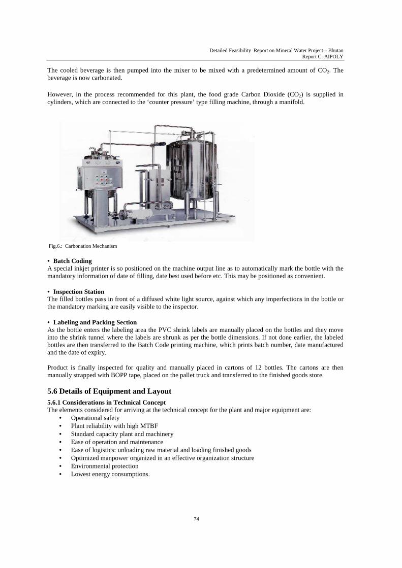
• Bottle Rinsing, Filling and Capping The bottles are then carried from the bottle blowing machine to the filling machine by the air conveyor. Here they are gripped by the neck. Thus, the system requires only two parts for change over – one capped star and one outfeed star. In the rinsing section, the bottles are rinsed by ozonised water with washing nozzles working under positive pump pressure. The gripping fingers and necessary guide bars will invert the bottles up side down by 180 degree to empty them after rinsing. They progress to the filling section, where they are taken by a star wheel under the filling nozzles. The bottles will be raised to the filling nozzle by positive lift cylinder. The bottle will be pressed against filling valves and same will open. If the bottle is not delivered, filling valve will not open. The water under gravity will be filled into the bottles. After filling, the bottle moves to the carbonating station, where the nozzle delivering the carbon dioxide from the cylinder manifold, enters the bottle and delivers a preset volume of the gas. Immediately on its withdrawal, the bottle enters the capping turret, where the washed cap, delivered by a hopper and a ‘pick and place’ arrangement, is placed on the bottle mouth. The cap is then firmly tightened by adjustable torque chucks, after which the duly capped bottle is transferred on the slat conveyor. The cap and neck is then sealed with a hologram bearing shrink seal. • Carbonation Carbonated water is made by passing pressurized carbon dioxide through water. The pressure increases the solubility and allows more carbon dioxide to dissolve than would be possible under standard atmospheric pressure. When the bottle is opened, the pressure is released, allowing the gas to come out of the solution. Thus, forming the characteristic bubbles. The pressure of supply and time of release determines the amount of gas injected into the water. When the pressure is kept high, it results in the water being converted to ‘soda’, which does not satisfy the thirst that water can. In the case of ‘sparkling’ water, a smaller amount of gas in injected into the bottle – this ensures that the taste of the water does not change, while a ‘refreshing’ feeling is imparted to its property of quenching thirst, thereby adding value to the plain water. A carbonation system combines a de-gassing system, chiller and CO2 mixer. The beverage is first filled into the de-gas tank; the Carbon Dioxide is injected into the tank to remove extra oxygen from the beverage. Then the beverage is pumped into the chiller and is cooled to a present temperature.
Fig. 5: Bottles after being formed are removed from
the two-cavity mould.
Fig. 3.b : Bottle Manufacturing Process
Detailed Feasibility Report on Mineral Water Project – Bhutan Report C: AIPOLY
74
Fig.6.: Carbonation Mechanism
The cooled beverage is then pumped into the mixer to be mixed with a predetermined amount of CO2. The beverage is now carbonated. However, in the process recommended for this plant, the food grade Carbon Dioxide (CO2) is supplied in cylinders, which are connected to the ‘counter pressure’ type filling machine, through a manifold.
• Batch Coding A special inkjet printer is so positioned on the machine output line as to automatically mark the bottle with the mandatory information of date of filling, date best used before etc. This may be positioned as convenient. • Inspection Station The filled bottles pass in front of a diffused white light source, against which any imperfections in the bottle or the mandatory marking are easily visible to the inspector. • Labeling and Packing Section As the bottle enters the labeling area the PVC shrink labels are manually placed on the bottles and they move into the shrink tunnel where the labels are shrunk as per the bottle dimensions. If not done earlier, the labeled bottles are then transferred to the Batch Code printing machine, which prints batch number, date manufactured and the date of expiry. Product is finally inspected for quality and manually placed in cartons of 12 bottles. The cartons are then manually strapped with BOPP tape, placed on the pallet truck and transferred to the finished goods store. 5.6 Details of Equipment and Layout
5.6.1 Considerations in Technical Concept The elements considered for arriving at the technical concept for the plant and major equipment are:
• Operational safety • Plant reliability with high MTBF • Standard capacity plant and machinery • Ease of operation and maintenance • Ease of logistics: unloading raw material and loading finished goods • Optimized manpower organized in an effective organization structure • Environmental protection • Lowest energy consumptions.

Detailed Feasibility Report on Mineral Water Project – Bhutan Report C: AIPOLY
75
Flow of Materials Flow of Water
Fig.7: Process Flow Chart – Sparkling Spring Natural Mineral Water Project at Aipoly
Source Collection of Spring Water
Storage
Marking
Bottle Filling
Raw Water Treatment
Visual Inspection
Bottle Body Labeling
Cap Sealing
Bottle Capping
Pet Granules
Cartons
Shrink Label
Packaging
Shrink Wrap
Cap
Bottle Pre-Wash
Bottle Pre-Form
Bottle Blowing
Inspection & Testing
A
B
C
D
D
E
E
E
E
E
E
Carbonation

Detailed Feasibility Report on Mineral Water Project – Bhutan Report C: AIPOLY
76
Based on the consultants’ experience with industry, the following norms are presented in tables 5.12 and 5.13: S. No. Department Operating Design Capacity Safety Factor Hrs/Day Days/Year Hrs/Year
1 Treatment Plant 24 300 7,200 1.3 2 Bottle Plant 16 300 4,800 1.2 3 Filling Plant 16 300 4,800 1.0 4 Packaging 16 300 4,800 1.3
Table 5.12: Operating Norms for Main Machinery S. No. Department Storage Units Remarks
1 Raw Water Storage 90 kilolitre 1.5 Days Production 6 SS Tanks Outdoors 2 Raw Material Store
PET Granules 4,200 kg 3 Days Production 1050 kg Packs in RM Store
3 Caps, Labels and Cap Seals Lot 3 Days Production In Raw Material Store 4 Cardboard Carton & Tape 12,000 Cartons 3 Days Production Finished Goods Store 5 Finished Goods 154,000 Litres 3 Days Production Finished Goods Store 6 Carbon Dioxide 18 Cylinder
of 31 kg each 1.5 Days Requirement Near Filling Machine
Table 5.13: Operating Norms for Main Storages 5.6.2 Detailed Specifications of the Main Plant & Machinery The basis of design of the rated capacity of the plant is the flow rate of the water supply as well as the rated production capacities of standard equipment. The requirement of packaging (raw) materials has been determined on the basis of finished product volumes. The broad sizing of main machinery has been determined by the nearest available standard equipment made by reliable manufacturers. Special consideration has been given to manufacturers who have a record of previous satisfactory supplies to plants in Bhutan. In selection of equipment capacity in the bottle manufacture and bottling lines, provision has been kept for laying an additional line to increase production, instead of installing the full capacity of the plant at the beginning. This has the advantage of lower first cost and faster return on investment. The sizing of storages has been estimated per item looking to its consumption and the lead-time expected in procurement of the item. However, the attempt will be to reduce the in-house inventory component and bring in the Just in Time concept for delivery of raw materials only when the consumption takes place. 5.6.3 Raw Material Preparation Capacity Spring Water Flow rate estimated at 60 litres per minute. However, this may increase with
drilling and insertion of infeed pipe into the aquifer after due investigation. Treatment of raw water drawn from storage tanks is done @ 5000 litres per hour.
Manufacture of PET Bottle
Of the available 60 lpm, the effective bottling is likely to be @ 50 litres per minute. Hence, the requirement of: 1 Litre bottle = 50 x 60 = 3,000 per hour Or 3,000 x 16 = 48,000 bottles per day Preform Moulding = 48,000 per day @ 22 gm Bottle Blowing = 48,000 per day
Available Excess Capacity of Water
19,080 Kilolitres per annum (Single shift operation) 11,800 Kilolitres per annum (Double shift operation)
Available Excess Capacity of Treatment Plant
21,600 Kilolitres per annum (Single shift operation) 14,400 Kilolitres per annum (Double shift operation)
Available Excess Capacity of Preform Molding
2.88 Million per annum (Single shift operation) 1.44 Million per annum (Double shift operation)
Available Excess Capacity of PET Bottle Blowing
Nil
Bottle Filling Line Nil Packaging Nil
Table 5.14: Raw Material and Linked Capacity

Detailed Feasibility Report on Mineral Water Project – Bhutan Report C: AIPOLY
77
The excess capacity is nil in bottling operations, since the plant is selected on the basis of capacity matching to requirement (a lean manufacturing system), and because equipment for 2nd shift operation will be installed only when the full plant potential is ready for marketing exploitation. 5.6.4 Production Equipment Capacity
S. No. Details 1 Raw Water Collection:
SS Perforated Draw Off Pipe diameter 76 mm inserted in the aquifer sufficient for the present flow. Manifold with 2” outlet, 3 measurement points and 1 outlet sample collection point.
2 Raw Water Transport: Water Delivery Pipe: HDPE Pipe 50 dia for leadoff to the plant.
3 Raw Water Storage: 6 nos. of SS 304 tanks of 15 kl capacity each, excess storage undesirable.
4 Raw Water Treatment: For IS 13428 and European CAC/RCP33-1985 (with amendments) Sand Filter: Removal of suspended particles & turbidity up to 10-micron size.
• FRP Tank, size 18” x 65” Max. working pressure 3.5 kg/cm2 Min 0.75 • Automatic valve operation for flow, rinse and regeneration. • Layer of sand for removing suspended particles up to 3 ppm.
Table 5.15: System Description 5.6.5 Bottling, filling, carbonation and capping: These operations are done on a single machine. Instead of installing one single machine with a capacity of 50 bottles per minute, it is recommended to install TWO machines of 25 bpm capacity. This will provide the same output, with the additional flexibility of permitting the production of two different sizes of bottles at the same time. 5.6.6 Manufacture of Accessories The following accessories may be considered for future expansion in other locations: 1. Carton Manufacturing Plant The requirement for this plant is 4000 cartons per day on 2 shift operation basis. A separate study could be
made to determine the cost effectiveness of setting up a cardboard carton manufacturing plant using raw material from Nepanagar, Assam or units in West Bengal / Orissa.
2. Cap Manufacturing Plant A separate plant may be set up if the requirement of other bottlers is also identified. It will then justify the
setting up of an Injection Moulding machine, which is the basic equipment, required for this project. 3. Label Manufacturing Press
It may be feasible to put in a two colour label printing machine to manufacture labels in house using adhesive film rolls.
5.6.7 Plant Layout Based on the process technological aspects, broad specifications of main plant and equipment, after the consultants’ knowledge about the area, the process flowchart for the proposed plant has been detailed in figure 8 on page no.77. Raw water from the spring is stored in the 6 nos. 15 kl tanks shown at the top right. These tanks are in the open but on the cemented platform of the Services Block. The water is drawn into the Treatment Plant and then pumped to the Rinsing-filling-capping unit. Bottles are made in the Bottle Blowing Plant and placed on a conveyor leading to the Rinsing-filling-capping unit, which will fill them and place them on the conveyor for packaging and storage.

Detailed Feasibility Report on Mineral Water Project – Bhutan Report C: AIPOLY
78
Source Feed
Finish Goods to Market
A
E
F
B
C
D G
H
Fig. 8: Process Equipment & Process Area Layout

Detailed Feasibility Report on Mineral Water Project – Bhutan Report C: AIPOLY
79
5.6.8 Technical Specifications for Plant & Equipment Based on above mentioned system design, broad specifications of the main plant and equipment, and the process flow chart, the proposed equipment with specifications is listed below:
I. Main Plant and Machinery S. No. Reference Item Specifications
1 A1 A2
Source Feed Pipe Inspection Manifold
SS 304 Dia 75mm x 5,000 mm Perforated Pipe SS 304 with dedicated instruments & sample draw faucet
2 C1 Pump SS 304 Construction Monobloc Pump HP capacity 5000 lph 3 C2 Sand Filter Tank, size 18’ X 65”3.5 kg/ cm2 (2 nos.) 4 C3 Carbon Filter Tank, size 18” X 65” kg/ cm2 (2 nos.) 5 C4 Conical Filter Micron rating of 10 microns, maximum pressure 3.5 kg/ cm2
and minimum working pressure 0.75 kg/ cm2 (2 nos.) 6 C5 Bag Filter Filter bag to trap 5 micron size particles as preliminary to finer
filters; bag is washable and reusable 7 C6 Cartridge Filter To achieve 1 micron clarity using 5 nos of 30” Cartridges 8 C7 Ultra Filtration
System High pressure pump for 5000 lph, 2 nos. membrane, 1 No. housing, 1 No. flow meter, TDS meter each, to remove macromolecules
9 C8 UV System SS Shell, 2 nos. Quartz Jacket, 2 nos. UV Lamps, with electrical control unit, indicators
10 C9 Ozonation System Complete with 3000 litre Storage tank, water pump, ozonator to supply 99.9% oxygen
11 D1, D2 PET Preform Injection Moulding Machine
Shot weight 425 gm; Clamping Force- 110T Platen size- 640 X 640; Tiebar Distance- 420 X 420, Mould Height- 200 X 450, Opening Stroke- 355 – 2 nos.
12 D3, D4 PET Blow Moulding Machine
5 Point Taper locking toggle; pneumatic operation; clamping stroke 110; max capacity 2 litre; article diameter 100 max – 2 nos.
13 E1, E2, E3, E4, E5, E6
Counter pressure Rinser-Filler-Capper
Automatic Rotary monoblock with 6-4-3 configuration, complete with infeed and outfeed conveyors, auto cap elevator – 2 nos.
14 F1, F2 Marking Machine Hitachi Ink Jet Printer PB Series for 2 line printing on bottle with indelible ink – 2 nos.
15 F3, F4
Shrink Tunnel
Online Combination Shrink Tunnel 2.5 m long for Cap Seal and Body Label assembly, linked to outfeed conveyor - 2 nos.
16 F5 , F6 Semi Auto Taping Machine
2” Taping Head using BOPP tape to seal both top & bottom of carton simultaneously – 2 nos.
Table 5.16: Description of Plant and Machinery II. Handling and Storage
S. No. Reference Item Specifications 1 B1 Raw Water Tank SS 304 Construction Dia 2500 x 3200 Height, suitably reinforced,
with inspection covers and level indicators; for holding raw water from source
2 D5, D6 Hopper For holding PET granules being fed to Preform Injection Moulding Machine; 2 nos; loaded manually by helper
3 D7 Transfer Bin Preforms drop into the bin for manual transfer to the Preheater 4 D8 Transfer Bin Blown bottles collection & transfer to Air Conveyor 5 E7 Air Conveyor
Blown bottles placed manually on Conveyor with High Pressure Blower for feeding bottles to Filler Monoblock
6 E8, E9 Cap Hopper and Elevator
Bought out caps manually loaded in hopper for feeding to Rinser-Filler-Capper – 2 nos.

Detailed Feasibility Report on Mineral Water Project – Bhutan Report C: AIPOLY
80
S. No. Reference Item Specifications 7 E10 Carbon Dioxide
Cylinder Manifold Manifold for connecting 6 nos. 31 kg cylinders
8 E11, E12 Delrin Conveyor Set of 2 nos 2.5m long with SS 304 Support Column for adjustment to bottle height, with variable speed drive to geared motors - to carry filled bottles to packaging station – 2 nos.
9 G1 Packaging Carton manually opened, bottles placed in it & flaps taped shut on Semi Auto Taping Machine. Carton then placed on pallet
10 G2 Hydraulic Pallet Lift Trolley
½ Ton Hydraulic Pallet Lifting Truck to carry stacked pallets to Finish Goods Store
Table 5.17: Handling and Storage Devices III Plant Utilities and Auxiliary Services
S. No. Reference Item Specifications
1 H1 Compressed Air System
• Model 15T2 Duplex package 35 kg/cm2 working pressure, 98.5 cfm, 40 HP with tank capacity of 500 litres
2 H2 Cooling Tower FRP, Induced Draft Counter Flow, 113,000 kcal/hr; 30TR
3 H3 Chilling Plant Air cooled compact water chiller, high volume, high pressure SS impellor with evaporator; cooling capacity 25.6 kw; R22
4 C10 Laboratory Equipment
See Appendix IV
5 C11, D6, E13, F7, G3
Miscellaneous Equipment
Fire Fighting Equipment
Table 5.18: Utilities and Auxiliary Facilities 5.6.9 Broad Details of Auxiliary Facilities
A. Utilities (except electrical power distribution system) The main services to the plant are:
1. Compressed Air: This is required for the PET Blowing Machines. The compressor has a built in receiver with automatic moisture drain control at a very high pressure, and the entire installation has to be carefully pressure tested by a qualified person and a certificate obtained (to be tested every 6 months). A 25 mm diameter steel pipe line of suitable thickness is preferred over C-class GI Pipe in the line going from the compressor installation outside the main building to the machine. At the point of use, there is another U-bend and automatic moisture drain trap.
2. Water for Staff and Sanitation Purposes: Covered overhead tanks are provided on the building for
holding excess spring water for drinking purposes. Other tanks are provided for holding water pumped from the river, to be used for sanitation purposes.
3. Cooling Tower: The water from the compressor and the PET Preform Injection Moulding Machine
is pumped through the cooling tower, which is designed with sufficient capacity to handle the cooling needs of both equipments. Further, the elevation of the site will aid the cooling process.
4. Chilling Plant: This plant is required to provide the low temperature water for cooling the mould in
the Injection Moulding machine. 5. Positive Air Pressure System: This is required to keep the shop environment clean by introducing
clean air through a forced draft ventilation system. Air is drawn in through large filter screens and blown inside the plant through strategically placed ducting. Further, air curtains are installed on the 2 major openings to ensure against entry of dirt.
Detailed Feasibility Report on Mineral Water Project – Bhutan Report C: AIPOLY
81
5.6.10 Quality Assurance The function of Quality Assurance is to ensure that all processes of water treatment and bottling are performed at the defined levels of quality. The definitions for quality of the water and its handling are contained in the standards IS: 13428:2005, IS: 14543:2004 and the Codex RCP 33-1985. The Quality Assurance plan is built upon:
1. Designing all processes to meet or exceed the stipulations contained in the standards. 2. Implementing the processes as designed, through selection of the best and most cost-effective
equipment available to do the job. 3. Operating the plant on a quality system to meet the Quality Systems Standard ISO 9001:2000. The
processes of continuous monitoring, sampling, testing and analysis are carried out to schedule and a system set in place for providing a feedback for effecting process corrections, where necessary.
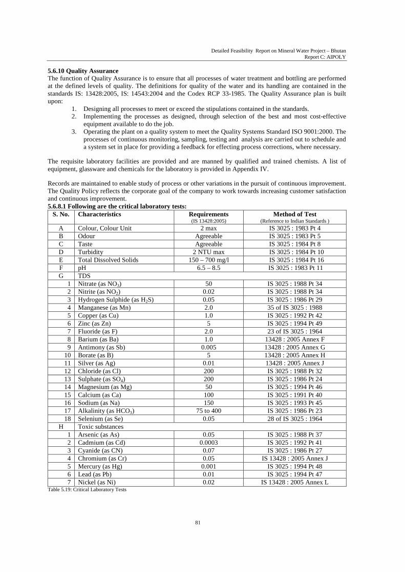
The requisite laboratory facilities are provided and are manned by qualified and trained chemists. A list of equipment, glassware and chemicals for the laboratory is provided in Appendix IV. Records are maintained to enable study of process or other variations in the pursuit of continuous improvement. The Quality Policy reflects the corporate goal of the company to work towards increasing customer satisfaction and continuous improvement. 5.6.8.1 Following are the critical laboratory tests:
S. No. Characteristics Requirements (IS 13428:2005)
Method of Test (Reference to Indian Standards )
A Colour, Colour Unit 2 max IS 3025 : 1983 Pt 4 B Odour Agreeable IS 3025 : 1983 Pt 5 C Taste Agreeable IS 3025 : 1984 Pt 8 D Turbidity 2 NTU max IS 3025 : 1984 Pt 10 E Total Dissolved Solids 150 – 700 mg/l IS 3025 : 1984 Pt 16 F pH 6.5 – 8.5 IS 3025 : 1983 Pt 11 G TDS
1 Nitrate (as NO3) 50 IS 3025 : 1988 Pt 34 2 Nitrite (as NO2) 0.02 IS 3025 : 1988 Pt 34 3 Hydrogen Sulphide (as H2S) 0.05 IS 3025 : 1986 Pt 29 4 Manganese (as Mn) 2.0 35 of IS 3025 : 1988 5 Copper (as Cu) 1.0 IS 3025 : 1992 Pt 42 6 Zinc (as Zn) 5 IS 3025 : 1994 Pt 49 7 Fluoride (as F) 2.0 23 of IS 3025 : 1964 8 Barium (as Ba) 1.0 13428 : 2005 Annex F 9 Antimony (as Sb) 0.005 13428 : 2005 Annex G
10 Borate (as B) 5 13428 : 2005 Annex H 11 Silver (as Ag) 0.01 13428 : 2005 Annex J 12 Chloride (as Cl) 200 IS 3025 : 1988 Pt 32 13 Sulphate (as SO4) 200 IS 3025 : 1986 Pt 24 14 Magnesium (as Mg) 50 IS 3025 : 1994 Pt 46 15 Calcium (as Ca) 100 IS 3025 : 1991 Pt 40 16 Sodium (as Na) 150 IS 3025 : 1993 Pt 45 17 Alkalinity (as HCO3) 75 to 400 IS 3025 : 1986 Pt 23 18 Selenium (as Se) 0.05 28 of IS 3025 : 1964
H Toxic substances 1 Arsenic (as As) 0.05 IS 3025 : 1988 Pt 37 2 Cadmium (as Cd) 0.0003 IS 3025 : 1992 Pt 41 3 Cyanide (as CN) 0.07 IS 3025 : 1986 Pt 27 4 Chromium (as Cr) 0.05 IS 13428 : 2005 Annex J 5 Mercury (as Hg) 0.001 IS 3025 : 1994 Pt 48 6 Lead (as Pb) 0.01 IS 3025 : 1994 Pt 47 7 Nickel (as Ni) 0.02 IS 13428 : 2005 Annex L
Table 5.19: Critical Laboratory Tests

Detailed Feasibility Report on Mineral Water Project – Bhutan Report C: AIPOLY
82
5.6.11 Spares and Tools Stores Suitable space is provided for keeping maintenance spares available at plant site, for meeting preventive maintenance needs as well as for emergency repairs. Workbench, vice and standard tools are maintained. Any special tools supplied by the equipment manufacturers are also kept securely here. All moulds and change parts for different bottling sizes are maintained in the main stores inside the main plant. 5.6.12 Other Facilities Change room and locker facilities are provided for all the workmen to change and put on protective clothing before entering the plant. The Time Office maintains attendance records. 5.7 Civil Engineering Considerations a. Site Conditions and Design Criteria The site conditions and design criteria are as follows in table 5.20.
S. No. Site Factors Site Conditions and Design Criteria 1 Topography There is not enough level land available at the source site for building a
treatment and bottling plant. As such, the recommended location for the Bottling plant is in the Iddi Village area. It is expected that a suitable area of approximately 4,000 sq. m will be available within a distance of 1 km from Aipoly, downhill from the source. A pipeline approximately 3000 ft long will be laid from the source to the plant.
2 Climatology Temperature (Hottest Day) Maximum : 36.5 oC, Minimum : 21.5 oC
(Coldest Night) Maximum : 30 oC, Minimum : 7 oC Humidity Maximum: 82%, Minimum: 72%
Maximum humidity occurs during July and August. Rainfall Maximum rainfall reported in the last 4 years is 1972.7 mm (in July, 2004).
3 Corrosion The site is by the bank of the river and there is no industry or polluting circumstance in the area. Vehicular traffic on the road is negligible as far as corrosion effects are concerned. Normal treatment to steel structures and usual precautions in execution of concrete structures are adequate.
4 Seismicity The proposed plant site falls in Seismic Zone IV, which has medium co-efficient of seismicity (as per Indian standards). This aspect shall be duly considered while designing the structures.
5 Sub-surface Conditions
Based on the preliminary investigation and reconnaissance survey of the site and adjoining areas, it is expected that hard strata would be encountered at a depth of barely 1 – 3 m below ground level. The sub soil stratum has boulders and clay/s. The requirement of pile foundations for the structures is not foreseen.
6 Ground Water The ground water table of the area is expected to be encountered at a depth of about 10-20 m below ground level. No special precautions for water proofing are indicated since there are no sub surface working spaces.
Table 5.20: Site Conditions and Design Criteria b. Brief Description of Major Civil Structures A brief Description of major civil structures is as follows in table 5.20.
S. No. Structure Specifications 1 Main Plant Main building is a single RCC structure housing all manufacturing and
office functions. The general layout is 150 ft x 80 ft in size, with an additional platform area of 20 ft x 80 ft for the services. If the land availability is a constraint, the office, Laboratories, change rooms and toilet facilities can be shifted to the 1st floor to reduce the ground floor area requirement of the building.

Detailed Feasibility Report on Mineral Water Project – Bhutan Report C: AIPOLY
83
S. No. Structure Specifications 2 Utilities Block This is an uncovered plinth area provided for the installation of the Cooling
Tower, Chilling Plant and Compressor, as well as the Stainless Steel Storage Tanks for raw water. The Main Electrical Distribution Board is also mounted on the external wall of the building, facing the plinth.
3 Time Office Block This is a separate construction near the entrance to the property. Attached with the Time Office is the Security or Guard Room, as well as the space for a small canteen.
4 Collection System The spring source area is waterproofed for rain water ingress and a 10 ft x 10 ft locked and fully enclosed structure is provided for the spring water intake manifold and instrumentation. Special precaution is required to prevent falling rock on the source room.
Table 5.20: Description of Major Civil Structures
c. Basic Building Structure
The main building shed will consist of RCC column structure with roof sheeting having following technical specifications:
S. No. Description Details 1 Frame type RCC column structure
2 Width (ft) 80 feet
3 Length (ft) 150 feet
4 Eave height (ft) 16 feet Clear
5 Interior column spacing (f) Equal
6 Roof slope 1:10
7 Bay spacing (f) 4 @ 18 f C/C
8 Type of end frames Light end frames
9 Wind bracing ROD bracing for roof and walls
10 Roof cladding 26 GA Colored Galvalume
11 Wall cladding 26 GA Colored Galvalume
12 Openings at front sidewall B/W Up to 10 feet & Above Shifted.
13 Openings at back sidewall B/W Up to 10 feet & Above Shifted
14 Openings at left end wall B/W Up to 10 feet & Above Shifted
15 Openings at right end wall Fully open for access to other end wall Table 5.22: Building Structural Considerations
d. Steel Work Finish S. No. Description Finish
1 Frames, Built-Up / HR sections Red oxide
2 Purlins / Grits / Bracings Red oxide
3 Anchor bolts Black (unpainted) Table 5.23: Steel Structure Finish
e. Design Loads
S. No. Description kN/m2
1 Dead load Self weight
2 Roof live load 0.57 kN/m2
3 Snow load NIL
4 Collateral load NIL
5 Wind load (Kmph or kN/m2) 47 M/S
6 Seismic load (zone no.) Will be considered during the actual structural design
7 Special loads NIL Table 5.24: Design Loads
Detailed Feasibility Report on Mineral Water Project – Bhutan Report C: AIPOLY
84
The main buildings shed will be designed in accordance with the following codes: - AISC Manual of Steel Construction – Allowable Stress Design. - AISI Cold Formed Steel Design Manual.
The buildings will be erected in accordance with the following codes: - AWS D1.1 Structural Welding Code. - MBMA Manual for Fabrication Tolerances
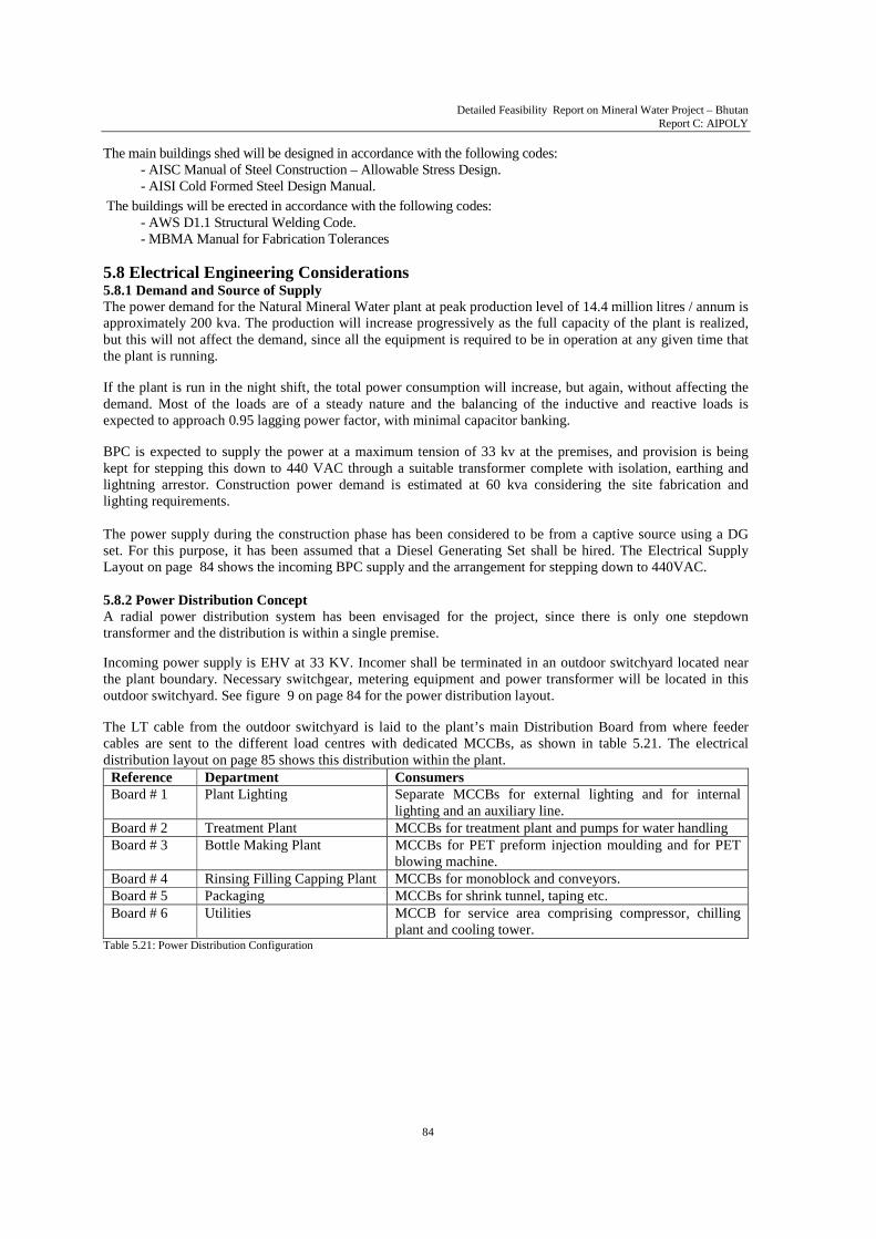
5.8 Electrical Engineering Considerations 5.8.1 Demand and Source of Supply The power demand for the Natural Mineral Water plant at peak production level of 14.4 million litres / annum is approximately 200 kva. The production will increase progressively as the full capacity of the plant is realized, but this will not affect the demand, since all the equipment is required to be in operation at any given time that the plant is running. If the plant is run in the night shift, the total power consumption will increase, but again, without affecting the demand. Most of the loads are of a steady nature and the balancing of the inductive and reactive loads is expected to approach 0.95 lagging power factor, with minimal capacitor banking. BPC is expected to supply the power at a maximum tension of 33 kv at the premises, and provision is being kept for stepping this down to 440 VAC through a suitable transformer complete with isolation, earthing and lightning arrestor. Construction power demand is estimated at 60 kva considering the site fabrication and lighting requirements. The power supply during the construction phase has been considered to be from a captive source using a DG set. For this purpose, it has been assumed that a Diesel Generating Set shall be hired. The Electrical Supply Layout on page 84 shows the incoming BPC supply and the arrangement for stepping down to 440VAC. 5.8.2 Power Distribution Concept A radial power distribution system has been envisaged for the project, since there is only one stepdown transformer and the distribution is within a single premise. Incoming power supply is EHV at 33 KV. Incomer shall be terminated in an outdoor switchyard located near the plant boundary. Necessary switchgear, metering equipment and power transformer will be located in this outdoor switchyard. See figure 9 on page 84 for the power distribution layout. The LT cable from the outdoor switchyard is laid to the plant’s main Distribution Board from where feeder cables are sent to the different load centres with dedicated MCCBs, as shown in table 5.21. The electrical distribution layout on page 85 shows this distribution within the plant. Reference Department Consumers Board # 1 Plant Lighting Separate MCCBs for external lighting and for internal
lighting and an auxiliary line. Board # 2 Treatment Plant MCCBs for treatment plant and pumps for water handling Board # 3 Bottle Making Plant MCCBs for PET preform injection moulding and for PET
blowing machine. Board # 4 Rinsing Filling Capping Plant MCCBs for monoblock and conveyors. Board # 5 Packaging MCCBs for shrink tunnel, taping etc. Board # 6 Utilities MCCB for service area comprising compressor, chilling
plant and cooling tower. Table 5.21: Power Distribution Configuration

Detailed Feasibility Report on Mineral Water Project – Bhutan Report C: AIPOLY
85
5.8.3 Salient Features of Electrical Systems Since all the equipment uses power at 440 VAC x 3Ph x 50 Hz, the power distribution is planned at 415 V to be stepped down from the 33 kV/ 0.433 kV, 250 kva Power Transformer located at the 33 kV outdoor line termination. The transformer will have natural cooling with “ON” load tap changer. Four earth points are provided, as well as the lightning arrestor feature. The 415 LT Distribution Board shall be of the fully draw-out type, along with motor operated Air Circuit Breakers (ACBs) and Moulded Case Circuit Breaker (MCCBs) with the necessary safety features to facilitate safe operation and easy maintenance. The DB is in a semi-enclosed enclosure on the outside wall of the plant. The plant loads are a good balance of motor loads with varying load cycles as well as heater type loads. There are no special heavy duty drives. For maintaining a high overall plant power factor, static power factor improving capacitor banks of suitable KVAR rating and voltage grade have been considered. Soft starts are provided with the heavier motors in the 20 HP range. Cables are laid in trenches and overhead racks along columns and beams. The electrical installation work will be carried out by qualified electrical contractors, and the execution will be governed by the Electricity Rules of Bhutan
5.8.4 Control Instrumentation and Automation The processes in the production of mineral water are discrete and there is no interlocking required between them. As such, the control instrumentation is for the individual unit automation logic, on a distributed technology concept.
On each equipment, there is a separate Programmable Logic Control Panel, which is capable of being set for different bottle sizes to be manufactured in the plant. The logic is maintained in the memory and can be recalled at the touch of a selector button. The PLC also monitors cycle parameters for proper interlocking.
Real time data shall be gathered for the MIS from the various discrete systems with the help of a data capture arrangement, which receives signals from the individual system control panel and translates them into meaningful figures for Management use. This data would be for recording the following real time data, typically:
• Quantity of water treated • Number of bottles made • Number of bottles filled • Number of cases packed
The control and instrumentation system envisaged incorporates the following essential features for evaluating operating performance:
• Colour, graphic and alphanumeric display with equipment fault monitoring system • Log trends for selected process parameters • Display of important process data • Printers for event & alarm list(s) and report generation • Machine supervision • Measurement of process parameters, data analysis and limit supervision • Handling of alarms and message information • Stores data on raw material stocks • Finish goods store data on daily dispatches
An Uninterrupted Power Supply (UPS) of adequate size shall be provided for catering to the power supplies for all control and instrumentation devices. A 5 x 15 line EPABX telephone exchange has been envisaged initially, with a provision to cater to additional subscribers, when required.

Detailed Feasibility Report on Mineral Water Project – Bhutan Report C: AIPOLY
86
5.8.5 Technical Specifications for Electrical Equipment Based on above mentioned system design, broad specifications of the main plant equipment, and process flow chart, brief specifications of electrical power distribution systems are as shown in table 5.22.
S. No. Item Specifications 1 Outdoor Switchyard 33 kV outdoor switchyard complete with lightning arrestors, isolators,
current transformers, potential transformers, circuit breaker. 2 Transformer 33/0.433 kV, 250 kVA, delta star, oil filled, class A insulated, on load tap
changer (range ± 10% with 2.5% step), and Impedance of 6% 3 LT Switchboard/
Main Power Distribution Board
415 V, 3 ph, 4 wire, 50 Hz, fully draw-out compartmentalized type, Aluminium bus bar (current density < 0.8 A/ mm2), IP 54 enclosure protection and floor mounted.
4 Motor Control Centers 415 V, 3 ph, 4 wire, 50 Hz, fully draw-out compartmentalized type, Aluminium bus bar (current density: < 0.8 A/ mm2), IP 54 enclosure protection, free standing, floor mounted.
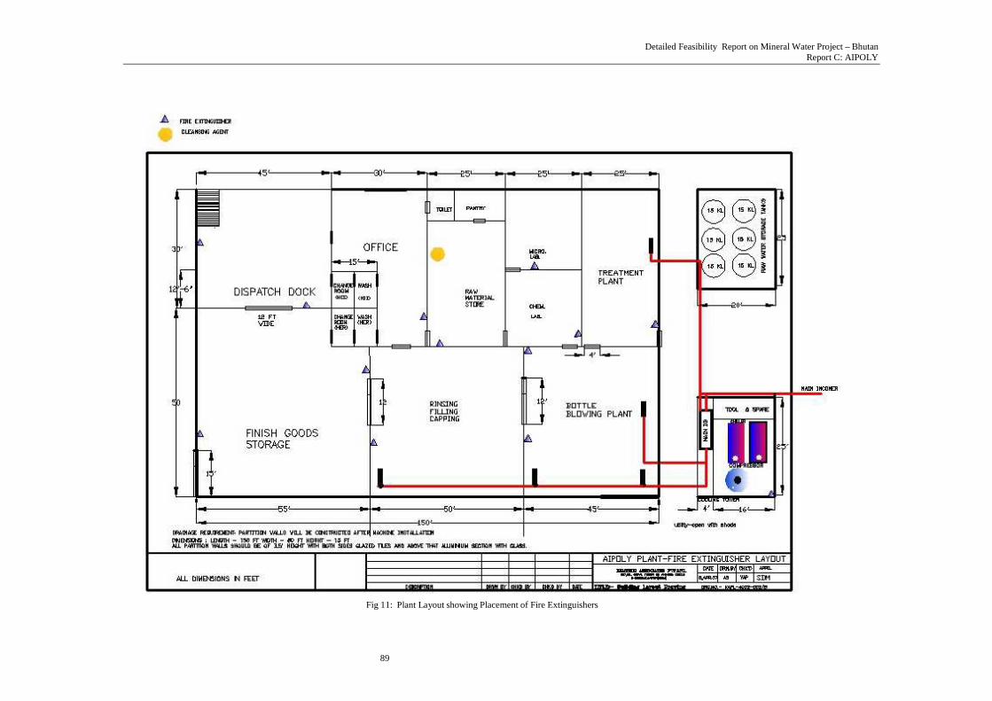
5 DG Set : only required at the time of construction Table 5.22: Technical Specifications for Electrical Equipment 5.9 Fire Fighting The planning for fire safety starts with the identification of the main fire hazards. These are found in the Stores (Raw material and finished goods), the PET bottle making plant and in the electrical distribution boards.
Accordingly, the following steps are taken:
1. Provision of smoke detectors (Ionization type dual chamber/ dual source smoke detectors) in the stores and bottle plant areas.
2. Arrangement for placing fire extinguishers at the strategic locations as shown in the diagram. 3. Training for all in use of the extinguishers, and conduct of fire safety drills for all staff and workmen.
Plant layout showing placement of fire extinguishers is given in figure 11on page 86 of this chapter.

Detailed Feasibility Report on Mineral Water Project – Bhutan Report C: AIPOLY
87
HT METER BOX CT-PT SET
FILLING PLANT
LIGHTING TREATMENT PLANT
BOTTLE PLANT
PARKING & OFFICE
DG SET 62.5KVA
DISTRIBUTION BOARDS
MAIN DB
TRANSFORMER
POWER SUPPLY
CHANGEOVER SWITCH
EARTH
PROJECT OFFTAKE
BPCL SUPPLY
Fig 9: Power Distribution Layout

Detailed Feasibility Report on Mineral Water Project – Bhutan Report C: AIPOLY
88
Fig. 10: Electrical Distribution Layout
Detailed Feasibility Report on Mineral Water Project – Bhutan Report C: AIPOLY
89
Fig 11: Plant Layout showing Placement of Fire Extinguishers

Detailed Feasibility Report on Mineral Water Project – Bhutan Report C: AIPOLY
90
[[[[[[[[
The site of the plant is assumed to be available at latitude 26o 55’ 15” N and longitude 90o 27’12” E, and is
pointed out on Toposheet No.78 E/11 (Survey of Bhutan), reproduced below in fig. 1:
Fig. 1: Topo Sheet Location of Spring Source at Aipoly and Proposed Plant Site
(Topo sheet scale = 1:50,000) 6.1 Availability of Land for Plant Site survey reveals that land is available in Iddi village about 1.5 km away from the source and 6 km from Gelephu. This village is being newly settled by persons relocated from other places. Land Lease: It is proposed to lease 4,000 sq m of land at the location from MTI at the rate of Nu 4.00 per sq ft per year rising to Nu 7.20 in the 10th year. This cost is detailed in table 9.3 in chapter 9.0.
6.0 Plant Location and Infrastructure
Detailed Feasibility Report on Mineral Water Project – Bhutan
Report C: AIPOLY
91
6.2 Site Data on Topography, Hydrology, Seismology and Site Development Required a. Topography About 6 km west of Gelephu on the Gelephu-Sarpang Road, one crosses the Paithak Khola (stream) bed, which is dry during the non-rainy seasons. Immediately before the stream, there is a village track turning off to the right alongside the left bank, and this rough kutcha ‘road’ winds north through a village for about 4 km to reach the right bank of the Aipoly Khola. The rough road continues north for about 2 km on the stream’s right bank beyond, which a vehicle cannot proceed due to the large boulders of the Khola bed. From here, a trek of about 2 km takes one along the boulder strewn stream course, crisscrossing the water. As one gets to the upper reaches, one has to negotiate one’s way around and over large boulders. The water course becomes very rugged and there is dense vegetation and sheer rock faces, particularly on the left bank. Along this left bank, one finds a good flow of water coming from a spring source under a quartzite boulder. b. Hydrology The present course of the Aipoly Khola is about 20 m west of the spring source but it is seen that the whole area was once the stream bed as indicated by sub-rounded boulders, gravel and sand through which the spring water comes out. The boulders are of quartzite and phyllite and they are sub-rounded to angular. Otherwise, above the spring, it is thickly jungled and there would be no problem of contamination from run off water. The rocks are mostly quartzite boulders of all sizes mixed with few phyllite boulders During preparation of the Detailed Project Report, it will be required to conduct a proper hydro-geological study of the spring source and its feeding aquifer. Such a study will require the following:
• Geo-electric Survey
In this investigation, computerized geo-electric monitors are used to evaluate electrical signatures of the aquifer system leading to determination of saturated thickness of subsurface i.e. water bearing formation, which is an important hydraulic parameter to assess quantification of water withdrawal at optimum level.
• Evaluation of Total Replenishable Water Reserves
Based on hydrological study and observation of all flow through the seasons, the total replenishable reserves are estimated & water extraction levels are recommended equivalent to rate of recharge computed for normal rainfall. These reserves are available for the long term, unless drought occurs for 5 to 7 years consecutively.
The survey is to be conducted by qualified technical personnel and the name and address of one vendor rendering this service is given in Appendix V. The costs to this head are estimated at Nu. 2,25,000 and the figure is shown in chapter 9.0 table 9.10‘Pre-operative Expenses’.
c. Seismology There is no evidence of faults in the area indicated by landslides. The area would generally be classified under Seismic Zone IV. 6.2.1 Site Development Required The site will require to be developed for protecting the source and for fencing the perimeter on the hillside, although there is no habitation in the area. The hill face at the source will require to be cemented to protect ingress of rainwater, as per standard practice and a Collection Room built on site, from where the water can be piped out to the treatment plant.
Detailed Feasibility Report on Mineral Water Project – Bhutan
Report C: AIPOLY
92
It may be appreciated that a detailed site survey will be required wherever the plant is to be sited, and only this will provide details of excavation or earthwork required. Budgetary costs of site development have been provided in table 9.5 ‘Fixed Assets - Building and Civil Work’ in chapter 9.0, under the following heads:
• Land Development Nu. 15.00 Lacs • Boundary wall and Gates Nu. 5.00 Lacs • Service Road inside Boundary Nu. 1.80 Lacs • Pipeline and Installation costs Nu. 5.25 Lacs
6.3 Services and Facilities for the Working Life Span of the Project A project is based upon the availability of certain services and facilities, which will be utilized in the exploitation of the natural resources. In a project for mineral water or any related industry, the basic services and facilities essential for the optimization of plant life may be from two sources - External and Internal. a. External: The following external services and facilities must remain available for the project to achieve its designed life span: � Spring Water The life span of the project is based upon the continued emergence of this natural water at the present
rate of flow viz. 60 litres per minute. � Law and Order The present environment is peaceful and conducive to the setting up of industries, in contrast with the
law and order situation across the border in Assam, India. � Power Power is an indispensable prerequisite and the commitment of the Bhutan Power Supply Corporation has
to be obtained for ensuring regular supply of the required power. Since the BPC policy is to provide power at 33 kv, comparatively heavy investment results in transforming the power to the required operating voltage of 440VAC. Since the power line is not likely to be moved, once installed, the expectation is of continued stable power. Details of the connected load of 93.35 kw have been shown in table 9.2.21.
� Labour Educated unemployed and untrained labour is available in Bhutan. Trained labour is available for starting
the project from India, but this is for the short term. Local hands are required for the long term operation of the plant, but they have to be trained in the requisite skills. As such, an intense skill development and training programme has been recommended in chapter 4.0 section 4.6.
� Stable Tax Regime The project has been found viable with the following conditions prevailing at present:
• Domestic tax structure of Bhutan • Free Trade Agreement with India • Ngultrum-Rupee parity and free convertibility
� Stable Industrial Policies on which Long Term Plans can be Based. The project has been based upon the present industrial policy, which promotes non-polluting industry, by
providing • Land on long term lease at reasonable rates. • Allocating power
The external environment must remain conducive to the furtherance of industry.

Detailed Feasibility Report on Mineral Water Project – Bhutan
Report C: AIPOLY
93
b. Internal: The plant is properly designed for giving a reasonable working life, but subsequently the following factors will affect the life: � Service for the Plant and Machinery The main condition for selection of plant and machinery is the proven reliability of the equipment backed
up by service guarantees of the manufacturers. This will be essential to ensure the service life of the project.
� Maintenance of Plant and Machinery
• The building, plant and machinery must be properly maintained. Services and repairs must be carried out to schedule, so that the 10 year working life span may be achieved.
• Quality spares and tooling must be kept available at all times, so that ad-hoc decisions on repairs are not required.
• Programmes for statistical monitoring of operational parameters must be included in the Management Information System.
� Extensive Training to Workmen and Staff on Quality in Work The skill development programme advised focuses on quality training. This continuous training
programme is very important for realizing the working life of the project, and focuses on • Inculcating quality consciousness in each employee • Training for all operatives on proper operation and upkeep • Developing a customer orientation in the organization
� Establishing a Strong HR Function Great importance is attached all over the world in the value of development of the human resource. This
is done by establishing the following: • A strong motivation to every employee to give of his best • A good appraisal system, which will monitor performance and pinpoint the employees strengths
and weaknesses
6.4 Transport Facilities The plant is close to the Gelephu – Sarpang Road, and there is little difficulty of public transport on the main road. For covering the distance from the main road to the plant, it may be expeditious for the company to arrange a chartered bus. Transport may be arranged from Gelephu to the site for senior staff and others. The site being close to the Indian Border at Gelephu is well connected for transportation of incoming materials and outgoing finished products. Provision has been made for purchase of a car for transport of officers and a mini-truck for the carriage of cartons of water. A total provision of Nu. 16.00 Lacs has been made as shown in chapter 9.0 table 9.8. 6.4.1 Effect on Project of Change in Plant Location Bottling of natural mineral water is required to be done as close to the site of the spring as possible, as defined by the Standard (see ‘IS 13428:2005, Item No. 3.Definition’ given in Appendix II). Should it be necessary to move the plant, the length of the Stainless Steel (SS) or High Density Polyethylene (HDPE) pipeline will increase, and stainless steel construction pumps will be required to maintain the flow. There will be extra costs for laying the pipeline and protecting it from damage due to natural factors like land slips or falling trees, as well as from human interventions. In this report, project costs have been considered based upon the Treatment and Bottling Plant being built far from the spring source because there is no level land in the immediate vicinity for setting up the treatment plant, but it is likely to be found within a kilometer of the source.

Detailed Feasibility Report on Mineral Water Project – Bhutan
Report C: AIPOLY
94
6.5 Ancillary Facilities Other than road transportation, there are no facilities such as residential accommodation, canteen services available in the immediate vicinity. However, it is seen that once an industry is started, all other required services grow up around it. The company may acquire land at a later stage to build its own colony.
6.6 Approach Road There is a proposal for building a connecting road from the Gelephu-Sarpang highway to a point further north of the site, where a monastery may be built. Till that happens, however, an approach road would have to be built from the main Gelephu – Sarpang road to the site, to permit the movement of vehicular traffic from the plant to the highway. A budgetary provision is kept in the preoperative expenses, shown in table 9.5 of chapter 9.0. as follows :
• Approach Road from Highway to Plant Nu. 10.00 Lacs 6.7 Personnel Housing, Schools, Hospitals etc. There is no habitation in the immediate vicinity. However, Gelephu, less than 6 km away, has many of the required personnel related facilities. 6.8 Communication Other than the road, there are no facilities such as telephone or post office immediately near the site. At present. Bhutan mobile phones do not work in the area but it is expected that regular telephone links would be established with the network expansion of Bhutan Telecom. Privately owned courier services are expected to come in once the plant is established and the need is felt.

Detailed Feasibility Report on Mineral Water Project – Bhutan
Report C: AIPOLY
95
This chapter covers the environment management aspects for the project. The degree of detail has been based
on the requirement as per the Environment Assessment Act 2000, and the regulations for Environmental Clearance of projects. Reference has been made to the Procedures for Project Review in the NEC guidelines. For mineral water project, which does not classify as category ‘A’, the broad parameters to be submitted for environment clearance are given below:
• Land Use • Soil • Ecology • Subsidence and Land slide • Noise Quality & Ground Vibration • Vehicular Movement
It is to be understood that the present study meets the requirements of Initial Environmental Evaluation (IEE), as per the norms prevalent in Bhutan. This does not, therefore, constitute a detailed Environment Assessment (EA), for which multi-seasonal, site-specific data has to be collected over a one-year time horizon. 7.1 Baseline Environmental Condition This project has no polluting processes, and there is no impact of atmospheric conditions such as temperature, rainfall or wind on the operation of the plant. However, the micro-meteorological data available for the location is presented in the following paragraphs. 7.1.1 Temperature
Year Hottest Day Temperature oC Coldest Night Temperature oC
Month Max. Min. Month Max. Min. 2003 August 34 23 January 26 11 2004 August 33 24 January 28 8.5 2005 September 33 23 January 30 9 2006 August 36.5 21.5 January 25 7
Table 7.1: Temperature Variation Range 7.1.2 Rainfall The rainy season generally extends over the period, April to September. The maximum rainfall usually occurs during June and July, and the minimum in the colder months, as seen in the table below:
Year Month Max. (mm) Month Min. (mm) 2003 June 1127 November 7.8 2004 July 1972.7 November 0 2005 July 1026.2 November 0 2006 June 946.6 January 0
Table 7.2: Rainfall Variation 7.1.3 Relative Humidity The annual average relative humidity varies between 72-82%. Maximum humidity occurs during July and August. The period, December-January, is relatively dry. 7.1.4 Wind Speed The maximum wind speed observed during the year is 5.7 m/ s in the month of July. The annual average wind speed ranges from 0.8-1.8 m/s. The general direction is easterly following the curve of the valley.
7.0 Environmental Assessment

Detailed Feasibility Report on Mineral Water Project – Bhutan
Report C: AIPOLY
96
7.2 Environmental Impacts The environmental impacts that may arise out of the proposed Mineral Water Plant, during the construction and operation phases, are summarized in the sub-sections that follow: 7.2.1 During Construction Phase S. No. Attributes Probable Impacts
1 Land Use Change from forest or human settlement use to industrial use. 2 Soil Loss of soil due to soil erosion is negligible. 3 Ecology Encroachment in ecology due removal of vegetation from built up area. 4 Water Resources Full appropriation of the existing spring.
Negligible loss in water supply potential of the river. 5 Water Quality Deterioration in downstream water quality of Aipoly Khola due to
discharge of construction site sanitary waste. 6 Air Quality No emission with no effect on air quality. 7 Noise Quality No increase in noise levels. 8 Vehicular Movement Little traffic congestion with barely any loss in air quality.
9 Solid Waste Potential of refuse, garbage, trash etc. at the construction site.
10 Aesthetics Plant is not near a major highway, hence will not be in sight. 11 Site of Cultural,
Historical and Scenic Importance
None
Table 7.3: Environmental Impact during Construction Phase 7.2. 2 During Operational Phase S. No. Attributes Probable Impacts
1 Land Use None 2 Soil None 3 Ecology None 4 Subsidence & Landslide
Problems None
5 Water Resources Full exploitation of spring water supply potential. 6 Hydrology None
7 Water Quality Small discharge of sewage and waste water.
8 Air Quality None 9 Noise Quality None 10 Vehicular Movement 8 Ton truck movements envisaged 11 Solid Waste Some solid waste generated 12 Aesthetics The plant building is away from major habitation centres 13 Site of Cultural,
Historical, Scenic Importance
Not applicable, no such structure in vicinity
14 Human Settlement Likely to increase in surrounding area. 15 Socio-Economic
condition Rural-to-Urban migration causes intensification of urban socio-economic problem. Increased economic activities in the region with additional jobs created leads to improvement in “Quality of Life” of people.
Table 7.4: Environmental Impact during Operational Phase
: Denotes action point
Detailed Feasibility Report on Mineral Water Project – Bhutan
Report C: AIPOLY
97
7.3 Environmental Management Mitigation measures including prevention and control for each environmental component has been delineated in the sub-sections that follow, for the components having any adverse impact, as marked in the tables above. These are listed under the Construction and Operational phase heads. 7.3.1 During Construction Phase
S. No. Attributes Mitigation Measures Proposed 1 Land Use Alternative land allotted for any prior allottees. 2 Soil Existing tree plantation to be culled only as construction progresses;
provision of ground sheets to reduce soil erosion. 3 Ecology Intense tree cultivation around plant site. Contractors to make
arrangements to meet the fuel demand of construction labour without disturbing the local sources.
4 Water Quality Provision of septic tanks for labour engaged in construction activities. 5 Solid Waste Proper collection, transportation and disposal system for construction
waste, refuse, garbage, trash, etc. 6 Vehicular Movement Construction vehicles to be well maintained to prevent breakdown or
accident. Table 7.5: Mitigation Measures during Construction Phase 7.3.2 During Operational Phase
S. No. Environmental Attributes Mitigation Measures Proposed 1 Land Use There is no present land use; higher human to land area ratio achieved
due to the employment generated. 2 Ecology Provision of compensatory afforestation. Collection of solid waste in
separate enclosures and disposal for sale to scrap dealers. 3 Water Quality Provision of sedimentation tanks to treat floor wash and general
cleaning runoff. Septic tanks for sewage disposal. 4 Socio Economic Condition Maintain good communication with local communities before, during
and after construction. Training of local personnel for specific (skilled) positions.
Table 7.6: Mitigation Measures during Operational Phase 7.3.3 Financial Outlay The following financial outlays have been provided for actions on points marked above in the table 7.3 & 7.4
S. No. Particulars Quantity Rate (Nu. in Lacs)
Amount (Nu. in Lacs)
1 Sedimentation Tanks 6’ x 8’ 4 0.10 0.40 2 Septic Tanks 4 0.35 1.40 3 Tree Plantation Lot 0.75 0.75 4 Waste Enclosures 4 0.15 0.60
Table 7.7: Financial Outlay for Mitigation Measures 7.4 Conclusion
a. There is no adverse impact on the environment. However, an environment management plan is to be cast integrally with the Quality Management System for the plant, to ensure that there is no carelessness in management of wastes.
b. There is a considerable improvement in the socio-economic environment, due to generation of direct employment of 84 persons, and indirect employment for several more who will provide support services for the plant.
c. The cost of the various mitigation measures as listed above is approximately Nu. 3.15 Lacs and this provision is made in the table 9.8 ‘Misc. Fixed Assets’.
d. Application as per the guidelines of NEC has to be submitted for environmental clearance before commencement of the project.
Detailed Feasibility Report on Mineral Water Project – Bhutan
Report C: AIPOLY
98
The successful implementation of a project has the following definition:
a. It is completed using planned inputs and there are no cost overruns. b. It is completed on time. c. It gives the outputs as planned.
The fundamental pre-requisite is good planning, which requires:
a. Clarity of direction, b. Availability and commitment of resources, c. Formulation of feasible goals, and d. Finding a good team leader.
Once the direction of the project is cleared and arrangements in place for mobilizing resources, the most important task of the Promoters is to find a good leader who can build a team to achieve the stated goals. This man must have a background of management of a unit as a profit centre and must be a dynamic go-getter, who aligns himself with his mission goals and is enthusiastic about them. He is an engineer ideally, but must have a strong marketing base, since he is required to plan and implement marketing strategy. His first task is to prepare the plan for project implementation, after first orienting himself fully on the location, the objective and the time frame. His second task is to build his core team. He has also to develop marketing strategies so that sales commence as soon as product becomes available. He has to plan for the product realization as shown in the following paragraphs. 8.1 Planning for Project Realization Project activities are broadly divided into three groups. The first group includes initiation activities leading to a positive decision to go ahead with the project. The second group includes pre-project activities related to obtaining environmental and infrastructural clearances, tying up financial and technology sources, site investigations, basic engineering and culminating in the order placement of the machinery. The third group includes implementation activities such as topographical surveys, detailed engineering, construction and erection and culminates in project commissioning. While the detailed overall project implementation schedule is shown in table 8.1, an overview of activities constituting each group is shown below. 8.1.1 Project Initiation Activities (Till investment decision for project)
• Project feasibility studies and preparation of detailed report • Due diligence of this report • Investment decision
8.1.2 Pre-project Activities (Till conclusion of contracts for main machinery) • Hydrological investigations for ensuring the availability of the requisite quantum of water. • Receipt of requisite clearances from competent authorities with respect to :
♦ Environmental clearance ♦ Sanction and supply of power ♦ Sanction and supply of water ♦ Recruitment of core team ♦ Tying up sources of funds for the project to achieve financial closure
8.0 Project Implementation
Detailed Feasibility Report on Mineral Water Project – Bhutan
Report C: AIPOLY
99
♦ Procurement of land ♦ Topographic survey for plant and collection area ♦ Site development
• Invitations for quotations from suppliers. • Basic engineering examination of quotations and preparation of comparative statements. • Floating tender inquiries, evaluation and placement of order for main machinery.
8.1.3 Project Activities (After conclusion of contracts for main machinery) • Topographic survey • Detailed engineering of the project • Procurement of auxiliary equipment & systems • Civil construction activities • Erection of machinery including installation of electrical equipment and instrumentation • Trial runs and commissioning of the plant
8.2 Method of Procurement of Plant and Equipment Procurement Specifications have already been laid out for plant and machinery and civil construction. Quotations have already been obtained to provide a reference base. With the formation of the company, it will be required to float enquiries and obtain quotations a fresh. This will be followed by detailed negotiations with the vendors, in which the following are to be finalized:
• Provision for handing over equipment duly installed and fully commissioned to planned capacity • Guarantees for equipment performance for one year or more • Provision of training of staff • Commercial terms
8.3 Key Factors / Strategies The principal strategy governing project implementation would perhaps be in relation to the implementation model chosen. The following implementation models are generally envisaged in the execution of a project.
• Turnkey, in which the project costs are generally about 20% higher than the shopping model but in which, the co-ordination is the best (with its possible implication on the project gestation period).
• Semi-turnkey, in which the project costs are about 10% higher than the shopping model, but in which, co-ordination is only about half as good as the turnkey model.
• Shopping, in which the project costs would be the lowest but, in which, co-ordination aspects are perhaps the most difficult.
Experience suggests that the Semi-turnkey Model would, perhaps, be the most appropriate under the circumstances in Bhutan. The key factors that would facilitate successful and timely project implementation are:
• Proper choice of machinery suppliers. • Adequate diligence in formulating the system design/selection of the plant. • Proper choice of contractors for civil construction and erection of equipment. • Formulation of an effective project team. • Establishment of an efficient system for project planning & monitoring including reporting procedures
for progress review and co-ordination.

Detailed Feasibility Report on Mineral Water Project – Bhutan
Report C: AIPOLY
100
[
8.4 Project Implementation Schedule The detailed overall project implementation schedule is shown in table 8.1. This schedule has been planned, keeping in view the expected delivery schedules (3-4 months ex-works basis) for all plant and machinery. Based on these and other inter-related activities, an implementation period of 12 months (after obtaining relevant permissions for land, power, environment clearance etc.) is considered feasible. This schedule will serve as a guideline for preparing a more detailed implementation schedule once project clearance is received, the main machinery supplier is finalized and the exact delivery schedule for equipment and information is known. Major milestones in the schedule are given in table 8.1:
S. No. Milestones Commencement Week
1 Receipt of final project report 1 2 Invitation to investors 2 3 Finalization of investor 5 4 Recruitment and selection of personnel for Planning Phase 10 5 Conduct of hydrological survey 11 6 Filing of applications for permissions 12 7 Invitations to suppliers to quote 12 8 Shortlisting of suppliers 15 9 Commencement of civil works 16 10 Final negotiations with suppliers 17 11 Order placement for machinery 18
12 Building flooring completion 44 13 Recruitment and selection of personnel for Erection Phase 44 14 Arrival and installation of machinery 44 15 Commencement of marketing tieups 44 16 Completion of building 48 17 Trial runs on machinery 48 18 Recruitment and selection of personnel for Operational Phase I 48 19 Chemical analysis at toxicological Lab 49 20 Trial production runs 50 21 Application for ISO9001:2000 certification 50 22 Clearance from lab 52 23 Commencement of production in 1 shift 52
24 ISO 9001:2000 certification audit 54 25 Recruitment and selection of personnel for Operational Phase II 54
26 Commencement of 2nd shift 62 Table 8.1: Project Implementation Schedule