Report ACC Draft
82
A Project Report On ADAPTIVE CRUISE CONTROL Submitted in the partial fulfillment of the Requirement for the award of the Bachelor’s Of Technology In MECHANICAL ENGINEERING Submitted By Moninderjeet Singh 6851114255 Naveen Kumar 6851114257 Navjot Sharma 6851114258 Pankaj Bhardwaj 6851114260 Puneet Bhasin 6851114268 Under the guidance of Mr. Ajay Saini Lecturer in Mechanical Department S.B.B.S.I.E.T, Jalandhar 1
-
Upload
yogeshkalia -
Category
Documents
-
view
52 -
download
1
Transcript of Report ACC Draft
A
Project Report
On
ADAPTIVE CRUISE CONTROLSubmitted in the partial fulfillment of the
Requirement for the award of the
Bachelor’s Of Technology
In
MECHANICAL ENGINEERING
Submitted By
Moninderjeet Singh 6851114255
Naveen Kumar 6851114257
Navjot Sharma 6851114258
Pankaj Bhardwaj 6851114260
Puneet Bhasin 6851114268
Under the guidance of
Mr. Ajay Saini
Lecturer in Mechanical Department
S.B.B.S.I.E.T, Jalandhar
Department of Mechanical Engineering
Sant Baba Bhag Singh Institute of Engineering & Technology
Vill. Khiala, P.O. Padhiana,Distt.Jalandhar
December 2009
1
TO WHOM IT MAY CONCERN
Certificate
This is to certify that Project entitled “ADAPTIVE CRUISE CONTROL ” is submitted in Partial fulfillment for the award of degree B.Tech (Mechanical Engineering) of Punjab Technical University has been successfully completed by Mr.Moninderjeet Singh having Roll No. 6851114255.They have done a satisfactory work under my Supervision/Guidance .
Name of Guide Name of Co-ordinator Name of H.O.D
Lect. Ajay Saini Sr. Lect. Sukhjeet Singh Dr. K.D. Mannan
2

TO WHOM IT MAY CONCERN
Certificate
This is to certify that Project entitled “ADAPTIVE CRUISE CONTROL ” is submitted in Partial fulfillment for the award of degree B.Tech (Mechanical Engineering) of Punjab Technical University has been successfully completed by Mr.Naveen Kumar having Roll No. 6851114257.They have done a satisfactory work under my Supervision/Guidance .
Name of Guide Name of Co-ordinator Name of H.O.D
Lect. Ajay Saini Sr.Lect. Sukhjeet Singh Dr. K.D. Mannan
3

TO WHOM IT MAY CONCERN
Certificate
This is to certify that Project entitled “ADAPTIVE CRUISE CONTROL ” is submitted in Partial fulfillment for the award of degree B.Tech (Mechanical Engineering) of Punjab Technical University has been successfully completed by Mr. Navjot Sharma having Roll No. 6851114258.They have done a satisfactory work under my Supervision/Guidance .
Name of Guide Name of Co-ordinator Name of H.O.D
Lect. Ajay Saini Sr.Lect. Sukhjeet Singh Dr. K.D. Mannan
4
TO WHOM IT MAY CONCERN
Certificate
This is to certify that Project entitled “ADAPTIVE CRUISE CONTROL ” is submitted in Partial fulfillment for the award of degree B.Tech (Mechanical Engineering) of Punjab Technical University has been successfully completed by Mr.Pankaj Bhardwaj having Roll No. 6851114260.They have done a satisfactory work under my Supervision/Guidance .
Name of Guide Name of Co-ordinator Name of H.O.D
Lect. Ajay Saini Sr.Lect. Sukhjeet Singh Dr. K.D. Mannan
5
TO WHOM IT MAY CONCERN
Certificate
This is to certify that Project entitled “ADAPTIVE CRUISE CONTROL ” is submitted in Partial fulfillment for the award of degree B.Tech (Mechanical Engineering) of Punjab Technical University has been successfully completed by Mr.Puneet Bhasin having Roll No. 6851114268.They have done a satisfactory work under my Supervision/Guidance .
Name of Guide Name of Co-ordinator Name of H.O.D
Lect. Ajay Saini Sr. Lect. Sukhjeet Singh Dr. K.D. Mannan
6
ACKNOWLEDGEMENT
We express our sincere gratitute to our Guide Mr. Ajay Saini(Lecturer,Mechanical Engineering Department ,Sant Baba Bhag Singh Institute of Engineering and Technology ,Padhiana) For her valuable guidiance ,proper advice,constructive suggestion and constant encouragement under her tutelege.
We would also like to thanks our assistor, Medhaavi Embedded Systems,Hoshiarpur who served as our supervisor and helped us in understanding the concept & electronics portion of the project.
We would like to convey our Gratitute to Dr.K.D Manan, H.O.D of our Mechanical Depatment, Project Head Mr. Sukhjeet Singh(Sr.Lecturer,Mechanical), with those expert guidance and support, this job would have been compelling.
We also pay our deep regard to all other staff member of our lab who helpd us by providing resources at the time of need.
We do not find enough words with which we can express our feeling of thanks to entire faculty and staff of Mechanical Department,Sant Baba Bhag Singh Institute of Engineering and Technology ,for their help,inspiration and moral support, which went a long way in successfully completion of our project.
We are also thankfull to our family members anfd friends for support and encouragement.
Moninderjeet Singh
Naveen Kumar
Navjot Sharma
Pankaj Bhardwaj
Puneet Bhasin
7
Table of Contents
1. Introduction to the Project.
2. Block Diagram
3. Circuit Diagram.
4. Component List.
5. Adaptive Cruise Control
6. Notes on Microcontroller
7. Code for Microcontroller
8. References
8

1. Introduction
The underlying technology behind this idea uses an intelligent & advanced electronic system to
control the speed of car. On a long & straight road, car driver can enable this function
(Automatic Cruise Control) & can relax. Driver would no longer be required to press accelerator
pedal as the speed of car is controlled by ACC.
In summary, for modern engine control systems, the vehicle speed regulation is a comfort
functionality.
ACC supports the driver to run at constant speed without pressing the accelerator pedal.
ACC releases the driver from the continuous surveillance of the speedometer.
ACC is very helpful at traveling long distances.
It uses a radar sensor to detect the distance to obstacle/another vehicle/animal in front.
It adjusts speed of the vehicle based on output of radar sensor.
It also applies brake based on the output of radar sensor.
Car will also be equipped with sensors which will check for any obstacle/another vehicle/animal
on the road, if there is so, speed decreases automatically and results into vehicle stoppage.
9
Vehicle Control
In this project we use two small gear dc motor for drive the small car. One motor for the left
wheel and one motor for the right wheel. Here we use powerful gear dc motor instead of stepper
motor. Stepper is not suitable for the drive the vehicle. Stepper motor is suitable for positioning
sensor but gear motor is suitable for the vehicle drive.
Motors
To make the concept car we need to have motors and the control circuitry that could control the
motors. There are different kinds of motors available for different application.
1. DC motor
2. Stepper motor
3. Servo motor
89C51 MICROCONTROLLER:
Is a 40 pin version of 51 family,. Program written for this controller is same for the all 8051
family controllers.
OPTOCOUPLER ( PC 817):
In this project we use optocoupler to provide a electrical isolation between process control
circuit and motor drive circuit. In this project we use separate supply for processor and control
circuit. Pc 817 is 4 pin ic. In this coupler two pin is input and two pin is output.
CRYSTAL.
In this project we use two crystal. One for the dtmf decoder and second with the microcontroller
Main use of the crystal is to provide a external frequency for the internal oscillator. With the
dtmf decoder we use crystal 3.58 Mhz and with the microcontroller we use 12 Mhz crystal.
10
DC MOTOR:
We use slow speed dc motor to drive the movement of vehicle. In this project we use two dc
motor. One for the drive the vehicle and second motor to change the direction of the vehicle.
H BRIDGE LOGIC:
H bridge logic is basically provide a forward and reverse logic to the motor.
DC motors:
These are the motors that are commonly found in the toys and the tape recorders. These
motors change the direction of rotation by changing the polarity. Most chips can't pass enough
current or voltage to spin a motor. Also, motors tend to be electrically noisy (spikes) and can
slam power back into the control lines when the motor direction or speed is changed.
Specialized circuits (motor drivers) have been developed to supply motors with power and to
isolate the other ICs from electrical problems. These circuits can be designed such that they can
be completely separate boards, reusable from project to project.
A very popular circuit for driving DC motors (ordinary or gearhead) is called an H-bridge. It's
called that because it looks like the capital letter 'H' on classic schematics. The great ability of an
H-bridge circuit is that the motor can be driven forward or backward at any speed, optionally
using a completely independent power source.
The H-Bridge with Enable Circuitry
11

It should be clear that one would never want to enable Transistors One and Two or Transistors
Three and Four simultaneously. This would cause current to flow from Power + to Power -
through the transistors, and not the motors, at the maximum current-handling capacity of either
the power supply or the transistors. This usually results in failure of the H-Bridge. To prevent the
possibility of this failure, enable circuitry as depicted in Figure is typically used.
In this circuit, the internal inverters ensure that the vertical pairs of transistors are never enabled
simultaneously. The Enable input determines whether or not the whole circuit is operational. If
this input is false, then none of the transistors are enabled, and the motor is free to coast to a stop.
By turning on the Enable input and controlling the two Direction inputs, the motor can be made
to turn in either direction.
Note that if both direction inputs are the same state (either true or false) and the circuit is
enabled, both terminals will be brought to the same voltage (Power + or Power - , respectively).
This operation will actively brake the motor, due to a property of motors known as back emf, in
which a motor that is turning generates a voltage counter to its rotation. When both terminals of
the motor are brought to the same electrical potential, the back emf causes resistance to the
motor's rotation.
12

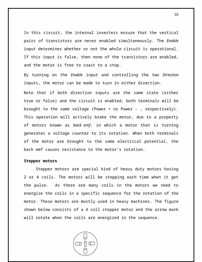
Stepper motors
Stepper motors are special kind of heavy duty motors having 2 or 4 coils. The motors will
be stepping each time when it get the pulse. As there are many coils in the motors we need to
energize the coils in a specific sequence for the rotation of the motor. These motors are mostly
used in heavy machines. The figure shown below consists of a 4 coil stepper motor and the arrow
mark will rotate when the coils are energized in the sequence.
Unlike DC motors stepper motors can be turned accurately for the given degrees.
Servo motors
Servo motors unlike the stepper motor it has to be controlled by the timing signal. This
motor has only one coil. It is mostly used in robots for its lightweight and low power
consumption. The servo motors can also be accurately rotated by the making the control signal of
the servo motor high for a specific time period. Actually the servo motor will be having 3 wires
where 2 are for power supply and another one is for the control signal. Driving the servomotors
is so simple that you need to make the control signal high for the specific amount of time. The
width of the pulse determines the output position of the shaft
Object Detection
Detecting objects without whiskers doesn’t require anything as sophisticated as machine vision.
Some robots use RADAR or SONAR (sometimes called SODAR when used in air instead of
water). An even simpler system is to use infrared light to illuminate the robot’s path and
determine when the light reflects off an object. The IR illuminators and detectors are readily
available and inexpensive.
13
Infrared As Headlights
The infrared object detection system we’ll build on the Bot is like a car’s headlights in several
respects. When the light from a car’s headlights reflects off obstacles, your eyes detect the
obstacles and your brain processes them and makes your body guide the car accordingly. We will
be using infrared LEDs for headlights. They emit infrared, and in some cases, the infrared
reflects off objects and bounces back in the direction of the detecter. The eyes of the
Bot( mobile) are the infrared detectors. The infrared detectors send signals to the Microcontroller
indicating whether or not they detect infrared reflected off an object. The brain of the Bot, the
microcontroller makes decisions and operates the motors based on this sensor input.
IN this project we use total tow motor so to control both the motor we require two H bridge
circuit. One for the one motor. Microcontroller sense the signal from the decimal decoder and
same output is connected to microcontroller and so on dc motor drive circuit. .
14

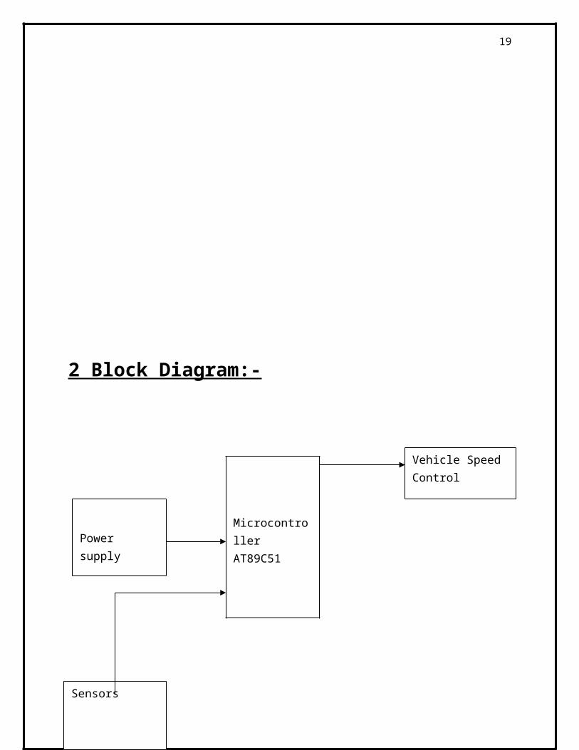
2 Block Diagram:-
15
Microcontroller AT89C51Power supply
Vehicle Speed Control
Sensors
3. Circuit Diagram:-
<D o c > <R e v C o d e >
<Tit le >
A 4
1 1F rid a y , A u g u s t 2 0 , 2 0 1 0
Tit le
S ize D o c u m e n t N u m b e r R e v
D a t e : S h e e t o f
+5 V
+5 V
+5 V
+5 V
+5 V
+5 V
+5 V
+5 V
+5 V
+5 V
+5 V
+5 V
+5 V
+5 V
+5 V
+5 V
+5 V
R 9
4 7 0 o h m
C 2
S W 1
4 7 0 o h m
U 1
A T8 9 C 5 1
91 81 9 2 9
3 0
3 1
12345678
2 12 22 32 42 52 62 72 8
1 01 11 21 31 41 51 61 7
3 93 83 73 63 53 43 33 2
R S TXTA L 2XTA L 1 P S E N
A L E / P R O G
E A / V P P
P 1 . 0P 1 . 1P 1 . 2P 1 . 3P 1 . 4P 1 . 5P 1 . 6P 1 . 7
P 2 . 0 / A 8P 2 . 1 / A 9
P 2 . 2 / A 1 0P 2 . 3 / A 1 1P 2 . 4 / A 1 2P 2 . 5 / A 1 3P 2 . 6 / A 1 4P 2 . 7 / A 1 5
P 3 . 0 / R XDP 3 . 1 / TXD
P 3 . 2 / I N TOP 3 . 3 / I N T1
P 3 . 4 / TOP 3 . 5 / T1
P 3 . 6 / W RP 3 . 7 / R D
P 0 . 0 / A D 0P 0 . 1 / A D 1P 0 . 2 / A D 2P 0 . 3 / A D 3P 0 . 4 / A D 4P 0 . 5 / A D 5P 0 . 6 / A D 6P 0 . 7 / A D 7
C 4
1 0 k
C 3
1 0 k
2 557
2
3
R
R
12 Mhz
1
R
TIP122
1
2
2
R
R
TIP122
TIP122
1
R
R
R
TIP122
R
B
R
557
B
R
R
TIP127
R
A
R
R
A
557
R
Rx
Rx
R
TIP127
R
TIP127
Tx
Tx
R
R
R
557
TIP127
R
R
R
16

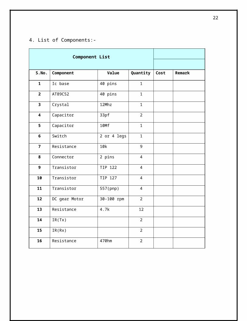
4. List of Components:-
Component List
S.No. Component Value Quantity Cost Remark
1 Ic base 40 pins 1
2 AT89C52 40 pins 1
3 Crystal 12Mhz 1
4 Capacitor 33pf 2
5 Capacitor 10Mf 1
6 Switch 2 or 4 legs 1
7 Resistance 10k 9
8 Connector 2 pins 4
9 Transistor TIP 122 4
10 Transistor TIP 127 4
11 Transistor 557(pnp) 4
12 DC gear Motor 30-100 rpm 2
13 Resistance 4.7k 12
14 IR(Tx) 2
15 IR(Rx) 2
16 Resistance 470hm 2
17
5. An introduction to Automatic Cruise Control
(ACC)
The surround sensing problem
Almost continuously, someone in the world dies from a traffic accident; countless more suffer
injuries. Moreover, the economic losses caused by traffic accidents
are reaching astronomical proportions. Vehicle manufacturers and their suppliers have made it
their goal to avoid such accidents, or at least to mitigate their effects. Much automotive safety
improvement can be made thanks to automotive electronics developments.
Analyses of the correlations between collisions and driver reactions have shown that a
considerable number of accidents can be avoided by recognizing a hazard in sufficient time and
making appropriate driving maneuvers. Such actions can be achieved by warning signals to the
driver or by automatic longitudinal and lateral control of the vehicle (Driver Assist Systems).
Suitable sensors are a requirement if the hazardous situations to be identified. A resulting sensor
network covers the area around the vehicle in conjunction with a suitable human-machine
interface. Electronic surround sensing systems form the basis of numerous river Assistance
Systems—systems for warning or active intervention. One area of these Driver Assistance
Systems is aimed at avoiding frontal collisions, which can be significantly reduced by accident
warning systems and active braking intervention. Adaptive Cruise Control (ACC) is the first step
in this direction.
Today’s ACC systems area mainly based on radar systems in the milli- meter wave range.
Millimeter wave radar systems are divided into pulsed and continuous wave systems, which are
in turn subdivided into frequency modulated continuous wave (FMCW) and spread spectrum
systems.
18
77 GHz FMCW radar systems allow objects to be detected within a range of 1 to 150m. At the same time, their distance and speed relative to the host vehicle—and with the right number of antennas, also their angle to the longitudinal axis of the vehicle—are determined.
Surround sensing systems—
Adaptive Cruise Control
Surround sensing systems forming the basis of numerous Driver Assistance Systems are
differentiated into:
• Ultrasonic-, radar-, video- and Navigation-based systems
• Passive and active systems
• Safety and convenience system
•Driver support, passive safety, collision mitigation, and vehicle control systems, according to
their function within the system.
Adaptive cruise Control system falls within the functional area of vehicle control and actively
intervenes in the longitudinal control of the vehicle. They decelerate the vehicle if it gets closer
than a set minimum distance from preceding vehicle and accelerate it to the set speed if there is
a sufficiently large gap. ACC systems are currently installed as convenience systems.
Their braking intervention is limited to a maximum of 30% of braking force capability; the
driver is in ultimate control of the vehicle. Current ACC systems are therefore particularly
suitable for roads with less traffic density, such as Interstates or highways. With additional
sensors, future ACC systems will be suitable for driving in heavy traffic in urban areas.
19
Further developments of ACC Stop-and-Roll (S&R) an ACC Stop-and-Go (S&G) are intended
to allow automatic stopping and starting in order to make lanes safer and improve traffic flow
The ultimate aim of these Driver Assistance Systems is 360-degree coverage of the area around
the vehicle; in the area of vehicle control, the goal is to expand the ACC function to achieve
complete longitudinal control.
Sensors for surround sensing
Covering the entire area around the vehicle requires a series of different sensors. Two types of
sensor, infrared (IR) sensors and long-range radar (LRR) sensors, are particularly well suited to
ACC. IR sensors are used in LIDAR (light detection and ranging) systems and cover a range of
up to 120m; in the case of 77 GHz LRR sensors, range can be extended up to 150m. IR sensors
offer a price advantage compared with LRR sensors, but have the marked disadvantage that poor
weather (heavy rain, snow, fog, dust, etc.) considerably reduces their working range.
Radar sensors, on the other hand, are almost entirely unaffected by weather conditions. Another
important argument in favor of radar sensors is that they can be mounted concealed in the front
of the vehicle; 77 GHz radar systems allow very small antenna sizes, permitting them to be
installed almost anywhere consequently, present ACC systems primarily use 77 GHz LRR
systems.
The main task of ACC is to decelerate the car if there is insufficient following distance to a
vehicle ahead or to accelerate if there is sufficient distance between vehicles. The control
parameters required for these tasks—desired driving speed
and time gap - are set by the driver via a human-machine interface (HMI). The entire control
function takes place in the sensor control unit (SCU). The main functions of the SCU are ACC
sensor control and object recognition. Calculation of the ACC control variables and activation of
the relevant systems are carried out in the ACC electronic control unit (ECU). Further processing
is done for the signals received by the ACC sensor. During object recognition, distance and
relative speed of all potential objects are calculated from the information contained in the
signals. Distance control requires the precise selection and regulation of a single object out of all
the objects detected by the ACC radar system.
20

Selection takes place using information on the vehicle’s movement, such as acceleration, wheel
speed, steering angle, and yaw rate. Using the host vehicle’s speed and the desired time interval,
the ACC system calculates the minimum separation distance required. If the distance calculated
for the selected object is too small for the current speed, the separation distance is adjusted and
deceleration commands are given to the appropriate systems (i.e. engine management, braking).
If the following distance is sufficient the speed is adjusted until the desired speed is reached. To
do this, acceleration commands are given to the relevant actuators. The specified time interval
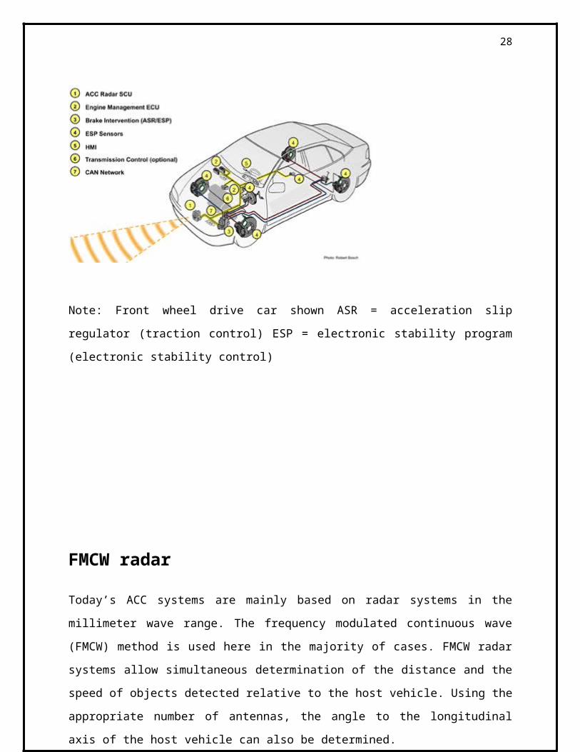
and warning signals if the minimum distance is not maintained are shown on the HMI display.
The diagram below shows the ACC system components and where they are installed in the
vehicle.
Note: Front wheel drive car shown ASR = acceleration slip regulator (traction control) ESP =
electronic stability program (electronic stability control)
21
FMCW radar
Today’s ACC systems are mainly based on radar systems in the millimeter wave range. The
frequency modulated continuous wave (FMCW) method is used here in the majority of cases.
FMCW radar systems allow simultaneous determination of the distance and the speed of objects
detected relative to the host vehicle. Using the appropriate number of antennas, the angle to the
longitudinal axis of the host vehicle can also be determined.
With the FMCW radar system the transmission frequency is varied linearly within the frequency
deviation, over the modulation period, the frequency curve of a transmit signal with three ramps.
In a static system where transmitter and object do not move, the frequency of the receive signal
lags behind the transmit signal. The difference between their frequencies is proportional to the
distance between transmitter and object.
Mixing transmits and receives signals results in a low-frequency intermediate frequency (IF).
The maximum frequency of the intermediate frequency is known as the beat frequency, If the
object moves relative to the transmitter, the frequency of the receive signal shifts due to the
Doppler Effect.
If the object approaches, the receive signal shifts to higher frequencies; if it moves further away,
to lower frequencies. If the distance is ignored, an approach at relative speed, Vrel, will result in
the receive signal, and consequently the constant intermediate frequency.
The superposition of the two cases in Figures B and C results in a receive signal where the
associated intermediate frequency contains both information on the distance and information on
the relative speed between transmitter and object.
The frequency curves for transmitter and object getting further apart at a relative speed, Vre The
intermediate frequency can be described using the FMCW radar equation (below) as a function
of distance, r, and relative speed. The sum describes the approach, the difference the distance
increase between transmitter and object. Where c = speed of light This is part 1 of a series.
22
6. Microcontroller (8051):-
WELCOME TO THE WORLD OF THE MICROCONTROLLERS.
Look around. Notice the smart “intelligent” systems? Be it the T.V, washing machines, video
games, telephones, automobiles, aero planes, power systems, or any application having a LED or
a LCD as a user interface, the control is likely to be in the hands of a micro controller!
Measure and control, that’s where the micro controller is at its best.
Micro controllers are here to stay. Going by the current trend, it is obvious that micro controllers
will be playing bigger and bigger roles in the different activities of our lives.
These embedded chips are very small, but are designed to replace components much bigger and
bulky In size. They process information very intelligently and efficiently. They sense the
environment around them. The signals they gather are tuned into digital data that streams
through tributaries of circuit lines at the speed of light. Inside the microprocessor collates and
calculators. The software has middling intelligence. Then in a split second, the processed streams
are shoved out.
23

What is the primary difference between a microprocessor
and a micro controller?
Unlike the microprocessor, the micro controller can be considered to be a true “Computer on a
chip”.
In addition to the various features like the ALU, PC, SP and registers found on a microprocessor,
the micro controller also incorporates features like the ROM, RAM, Ports, timers, clock circuits,
counters, reset functions etc.
While the microprocessor is more a general-purpose device, used for read, write and calculations
on data, the micro controller, in addition to the above functions also controls the environment.
The 8051:
The 8051 developed and launched in the early 80`s, is one of the most popular micro controller
in use today. It has a reasonably large amount of built in ROM and RAM. In addition it has the
ability to access external memory.
The generic term `8x51` is used to define the device. The value of x defining the kind of ROM,
i.e. x=0, indicates none, x=3, indicates mask ROM, x=7, indicates EPROM and x=9 indicates
EEPROM or Flash.
A note on ROM:
The early 8051, namely the 8031 was designed without any ROM. This device could run only
with external memory connected to it. Subsequent developments lead to the development of the
PROM or the programmable ROM. This type had the disadvantage of being highly
unreliable.The next in line, was the EPROM or Erasable Programmable ROM. These devices
used ultraviolet light erasable memory cells. Thus a program could be loaded, tested and erased
using ultra violet rays. A new program could then be loaded again.
24
An improved EPROM was the EEPROM or the electrically erasable PROM. This does not
require ultra violet rays, and memory can be cleared using circuits within the chip itself.
Finally there is the FLASH, which is an improvement over the EEPROM. While the terms
EEPROM and flash are sometimes used interchangeably, the difference lies in the fact that flash
erases the complete memory at one stroke, and not act on the individual cells. This results in
reducing the time for erasure.
Different microcontrollers in market.
PIC :
One of the famous microcontrollers used in the industries. It is based on RISC Architecture
which makes the microcontroller process faster than other microcontroller.
INTEL:
These are the first to manufacture microcontrollers. These are not as sophisticated other
microcontrollers but still the easiest one to learn.
ATMEL:
Atmel’s AVR microcontrollers are one of the most powerful in the embedded industry. This
is the only microcontroller having 1kb of ram even the entry stage. But it is unfortunate that in
India we are unable to find this kind of microcontroller.
25
Intel 8051
Intel 8051 is CISC architecture which is easy to program in assembly language and also has a
good support for High level languages.
The memory of the microcontroller can be extended up to 64k.
This microcontroller is one of the easiest microcontrollers to learn.
The 8051 microcontroller is in the field for more than 20 years. There are lots of books and study
materials are readily available for 8051.
Derivatives
The best thing done by Intel is to give the designs of the 8051 microcontroller to everyone. So it
is not the fact that Intel is the only manufacture for the 8051 there more than 20 manufactures,
with each of minimum 20 models. Literally there are hundreds of models of 8051
microcontroller available in market to choose. Some of the major manufactures of 8051 are
Atmel
Philips
Philips
The Philips‘s 8051 derivatives has more number of features than in any microcontroller.
The costs of the Philips microcontrollers are higher than the Atmel’s which makes us to choose
Atmel more often than Philips.
Dallas:
Dallas has made many revolutions in the semiconductor market. Dallas’s 8051 derivative is the
fastest one in the market. It works 3 times as fast as a 8051 can process. But we are unable to get
more in India.
26
Atmel:
These people were the one to master the flash devices. They are the cheapest microcontroller
available in the market. Atmel’s even introduced a 20pin variant of 8051 named 2051. The
Atmel’s 8051 derivatives can be got in India less than 70 rupees. There are lots of cheap
programmers available in India for Atmel. So it is always good for students to stick with 8051
when you learn a new microcontroller.
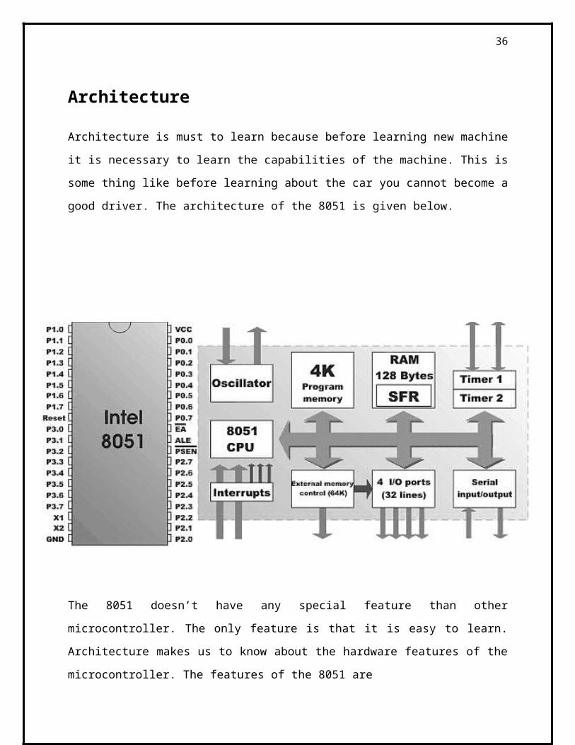
Architecture
Architecture is must to learn because before learning new machine it is necessary to learn the
capabilities of the machine. This is some thing like before learning about the car you cannot
become a good driver. The architecture of the 8051 is given below.
The 8051 doesn’t have any special feature than other microcontroller. The only feature is that it
is easy to learn. Architecture makes us to know about the hardware features of the
microcontroller. The features of the 8051 are
27
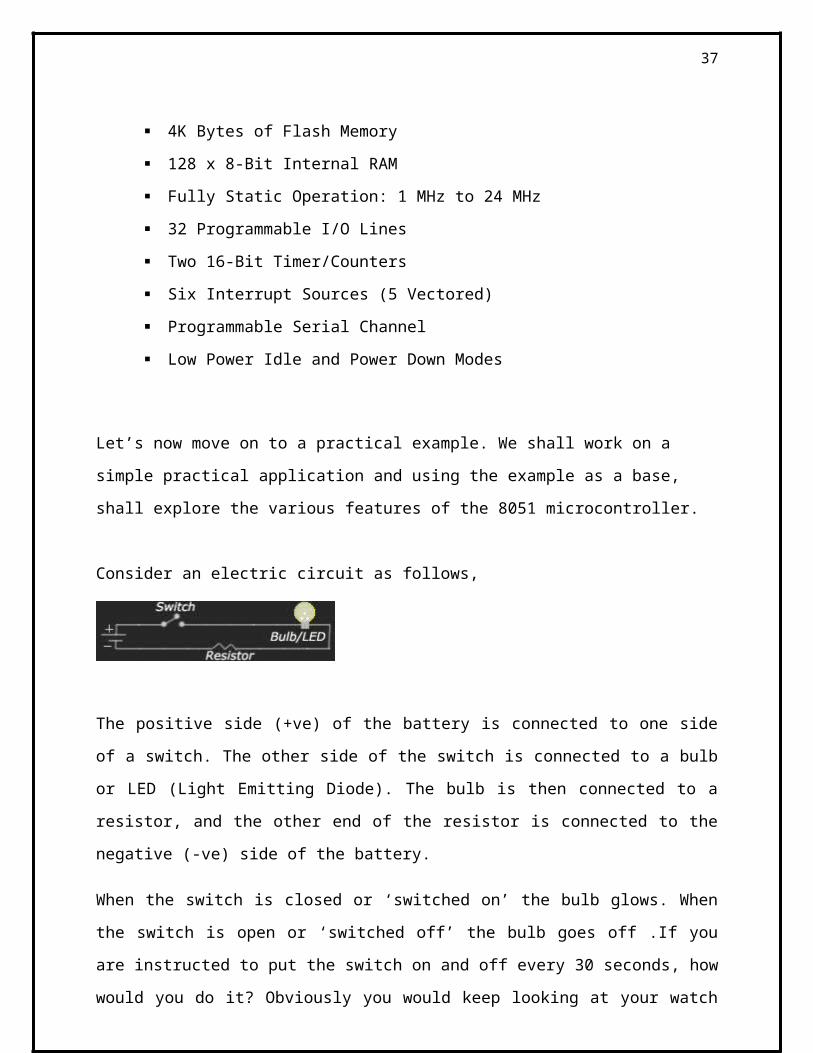
4K Bytes of Flash Memory
128 x 8-Bit Internal RAM
Fully Static Operation: 1 MHz to 24 MHz
32 Programmable I/O Lines
Two 16-Bit Timer/Counters
Six Interrupt Sources (5 Vectored)
Programmable Serial Channel
Low Power Idle and Power Down Modes
Let’s now move on to a practical example. We shall work on a simple practical application and
using the example as a base, shall explore the various features of the 8051 microcontroller.
Consider an electric circuit as follows,
The positive side (+ve) of the battery is connected to one side of a switch. The other side of the
switch is connected to a bulb or LED (Light Emitting Diode). The bulb is then connected to a
resistor, and the other end of the resistor is connected to the negative (-ve) side of the battery.
When the switch is closed or ‘switched on’ the bulb glows. When the switch is open or ‘switched
off’ the bulb goes off .If you are instructed to put the switch on and off every 30 seconds, how
would you do it? Obviously you would keep looking at your watch and every time the second
hand crosses 30 seconds you would keep turning the switch on and off.
Imagine if you had to do this action consistently for a full day. Do you think you would be able
to do it? Now if you had to do this for a month, a year??
No way, you would say!
The next step would be, then to make it automatic. This is where we use the Microcontroller.
But if the action has to take place every 30 seconds, how will the microcontroller keep track of
time?
28
Execution time
Look at the following instruction,
clr p1.0
This is an assembly language instruction. It means we are instructing the microcontroller to put a
value of ‘zero’ in bit zero of port one. This instruction is equivalent to telling the microcontroller
to switch on the bulb. The instruction then to instruct the microcontroller to switch off the bulb
is,
Set p1.0
This instructs the microcontroller to put a value of ‘one’ in bit zero of port one.
Don’t worry about what bit zero and port one means. We shall learn it in more detail as we
proceed.
There are a set of well defined instructions, which are used while communicating with the
microcontroller. Each of these instructions requires a standard number of cycles to execute. The
cycle could be one or more in number.
How is this time then calculated?
The speed with which a microcontroller executes instructions is determined by what is known as
the crystal speed. A crystal is a component connected externally to the microcontroller. The
crystal has different values, and some of the used values are 6MHZ, 10MHZ, and 11.059 MHz
etc.
Thus a 10MHZ crystal would pulse at the rate of 10,000,000 times per second.
The time is calculated using the formula.
No of cycles per second = Crystal frequency in HZ / 12.
For a 10MHZ crystal the number of cycles would be,
29
10,000,000/12=833333.33333 cycles.
This means that in one second, the microcontroller would execute 833333.33333 cycles.
Therefore for one cycle, what would be the time? Try it out.
The instruction clr p1.0 would use one cycle to execute. Similarly, the instruction setb p1.0 also
uses one cycle.
So go ahead and calculate what would be the number of cycles required to be executed to get a
time of 30 seconds!
Getting back to our bulb example, all we would need to do is to instruct the microcontroller to
carry out some instructions equivalent to a period of 30 seconds, like counting from zero
upwards, then switch on the bulb, carry out instructions equivalent to 30 seconds and switch off
the bulb.
Just put the whole thing in a loop, and you have a never ending on-off sequence.
Let us now have a look at the features of the 8051 core, keeping the above example as a
reference,
1. 8-bit CPU.( Consisting of the ‘A’ and ‘B’ registers)
Most of the transactions within the microcontroller are carried out through the ‘A’ register, also
known as the Accumulator. In addition all arithmetic functions are carried out generally in the
‘A’ register. There is another register known as the ‘B’ register, which is used exclusively for
multiplication and division.
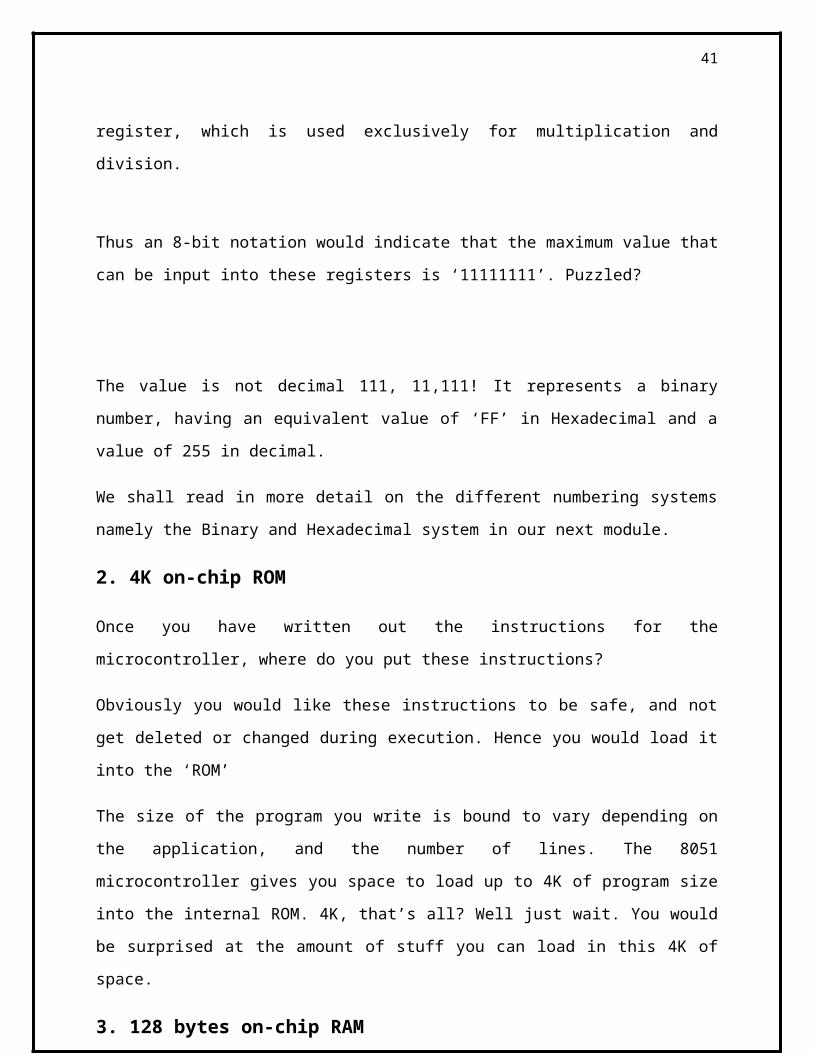
Thus an 8-bit notation would indicate that the maximum value that can be input into these
registers is ‘11111111’. Puzzled?
30
The value is not decimal 111, 11,111! It represents a binary number, having an equivalent value
of ‘FF’ in Hexadecimal and a value of 255 in decimal.
We shall read in more detail on the different numbering systems namely the Binary and
Hexadecimal system in our next module.
2. 4K on-chip ROM
Once you have written out the instructions for the microcontroller, where do you put these
instructions?
Obviously you would like these instructions to be safe, and not get deleted or changed during
execution. Hence you would load it into the ‘ROM’
The size of the program you write is bound to vary depending on the application, and the number
of lines. The 8051 microcontroller gives you space to load up to 4K of program size into the
internal ROM. 4K, that’s all? Well just wait. You would be surprised at the amount of stuff you
can load in this 4K of space.
3. 128 bytes on-chip RAM
This is the space provided for executing the program in terms of moving data, storing data etc.
4. 32 I/O lines. (Four- 8 bit ports, labeled P0, P1, P2, P3)
In our bulb example, we used the notation p1.0. This means bit zero of port one. One bit controls
one bulb.
Thus port one would have 8 bits. There are a total of four ports named p0, p1, p2, p3, giving a
total of 32 lines. These lines can be used both as input or output.
31
5. Two 16 bit timers / counters.
A microcontroller normally executes one instruction at a time. However certain applications
would require that some event has to be tracked independent of the main program. The
manufacturers have provided a solution, by providing two timers. These timers execute in the
background independent of the main program. Once the required time has been reached,
(remember the time calculations described above?), they can trigger a branch in the main
program.
These timers can also be used as counters, so that they can count the number of events, and on
reaching the required count, can cause a branch in the main program.
6. Full Duplex serial data receiver / transmitter.
The 8051 microcontroller is capable of communicating with external devices like the PC etc.
Here data is sent in the form of bytes, at predefined speeds, also known as baud rates.
The transmission is serial, in the sense, one bit at a time.
7. 5- interrupt sources with two priority levels (Two external and three
internal)
During the discussion on the timers, we had indicated that the timers can trigger a branch in the
main program. However, what would we do in case we would like the microcontroller to take the
branch, and then return back to the main program, without having to constantly check whether
the required time / count has been reached?
This is where the interrupts come into play. These can be set to either the timers, or to some
external events. Whenever the background program has reached the required criteria in terms of
time or count or an external event, the branch is taken, and on completion of the branch, the
control returns to the main program.
32
Priority levels indicate which interrupt is more important, and needs to be executed first in case
two interrupts occur at the same time.
8. On-chip clock oscillator.
This represents the oscillator circuits within the microcontroller. Thus the hardware is reduced to
just simply connecting an external crystal, to achieve the required pulsing rate.
PIN Description OF IC 89C51.
1 Supply pin of this ic is pin no 40. Normally we apply a 5 volt regulated dc power
supply to this pin. For this purpose either we use step down transformer power supply
or we use 9 volt battery with 7805 regulator.
2 Ground pin of this ic is pin no 20. Pin no 20 is normally connected to the ground pin
(Normally negative point of the power supply.
3 XTAL is connected to the pin no 18 and pin no 19 of this ic. The quartz crystal
oscillator connected to XTAL1 and XTAL2 PIN. These pins also needs two
capacitors of 30 pf value. One side of each capacitor is connected to crystal and other
pins is connected to the ground point. Normally we connect a 12 MHz or 11.0592
MHz crystal with this ic.. But we use crystal upto 20 MHz to this pins.
4 RESET PIN.. Pin no 9 is the reset pin of this ic.. It is an active high pin. On
applying a high pulse to this pin, the micro controller will reset and terminate all
activities. This is often referred to as a power on reset. The high pulse must
be high for a minimum of 2 machine cycles before it is allowed to go low.
5. PORT0 Port 0 occupies a total of 8 pins. Pin no 32 to pin no 39. It can be used for
input or output. We connect all the pins of the port 0 with the pullup resistor (10 k
ohm) externally. This is due to fact that port 0 is an open drain mode. It is just like a
open collector transistor.
6. PORT1. ALL the ports in microcontroller are 8 bit wide pin no 1 to pin no 8
because it is a 8 bit controller. All the main register and sfr all is mainly 8 bit wide.
Port 1 is also occupies a 8 pins. But there is no need of pull up resistor in this port.
Upon reset port 1 act as a input port. Upon reset all the ports act as a input port
33
7. PORT2. Port 2 also have a 8 pins. It can be used as a input or output. There is no need of
any pull up resistor to this pin.
8. PORT 3. Port3 occupies a total 8 pins from pin no 10 to pin no 17. It can be used as
input or output. Port 3 does not require any pull up resistor. The same as port 1 and
port2. Port 3 is configured as an output port on reset. Port 3 has the additional
function of providing some important signals such as interrupts. Port 3 also use for
serial communication.
9. ALE ALE is an output pin and is active high. When connecting an 8031 to external
memory, port 0 provides both address and data. In other words, the 8031 multiplexes
address and data through port 0 to save pins. The ALE pin is used for de-multiplexing
the address and data by connecting to the IC 74ls373 chip.
10. PSEN. PSEN stands for program store enable. In an 8031 based system in which an
external rom holds the program code, this pin is connected to the OE pin of the rom.
11. EA. EA. In 89c51 8751 or any other family member of the ateml 89c51 series all come
with on-chip rom to store programs, in such cases the EA pin is connected to the Vcc.
For family member 8031 and 8032 is which there is no on chip rom, code is stored in
external memory and this is fetched by 8031. In that case EA pin must be connected
to GND pin to indicate that the code is stored externally.
34
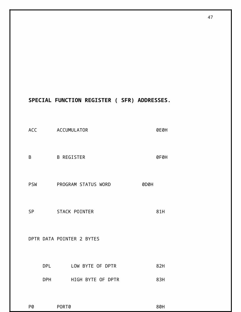
SPECIAL FUNCTION REGISTER ( SFR) ADDRESSES.
ACC ACCUMULATOR 0E0H
B B REGISTER 0F0H
PSW PROGRAM STATUS WORD 0D0H
SP STACK POINTER 81H
DPTR DATA POINTER 2 BYTES
DPL LOW BYTE OF DPTR 82H
DPH HIGH BYTE OF DPTR 83H
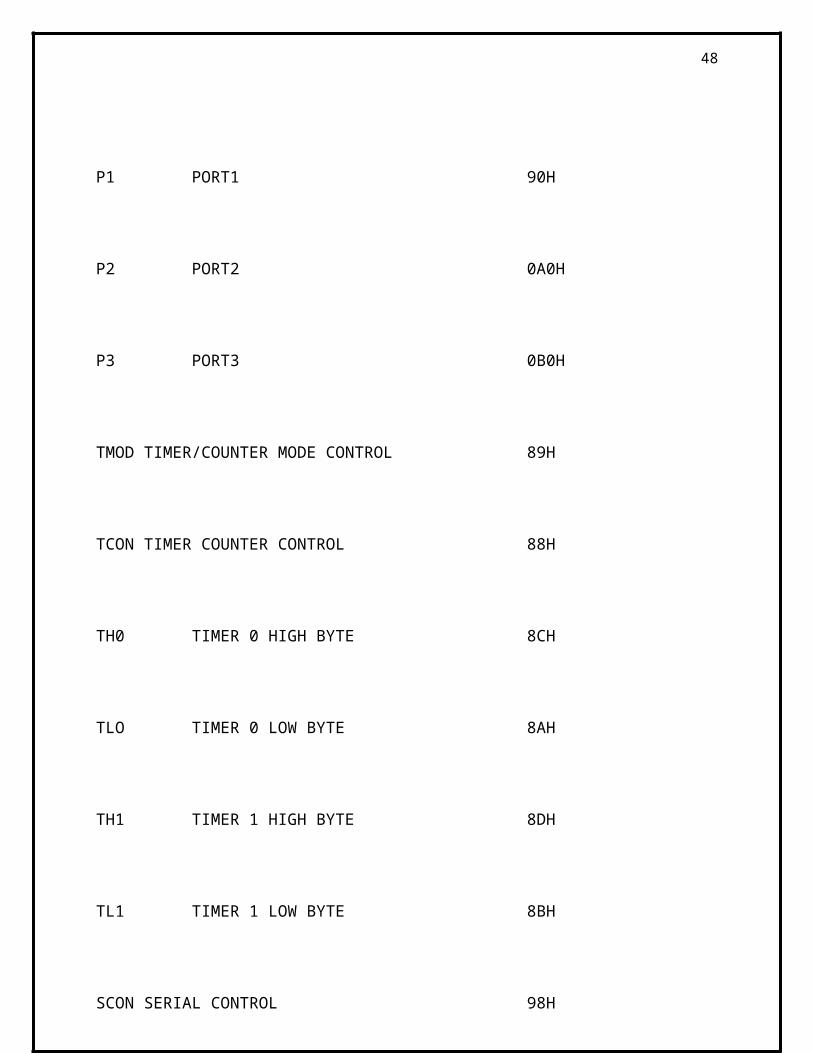
P0 PORT0 80H
P1 PORT1 90H
P2 PORT2 0A0H
P3 PORT3 0B0H
35
TMODTIMER/COUNTER MODE CONTROL 89H
TCON TIMER COUNTER CONTROL 88H
TH0 TIMER 0 HIGH BYTE 8CH
TLO TIMER 0 LOW BYTE 8AH
TH1 TIMER 1 HIGH BYTE 8DH
TL1 TIMER 1 LOW BYTE 8BH
SCON SERIAL CONTROL 98H
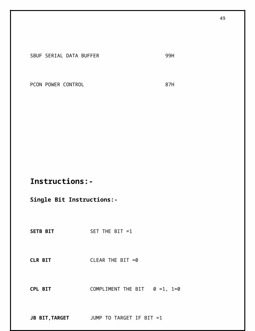
SBUF SERIAL DATA BUFFER 99H
PCON POWER CONTROL 87H
36
Instructions:-
Single Bit Instructions:-
SETB BIT SET THE BIT =1
CLR BIT CLEAR THE BIT =0
CPL BIT COMPLIMENT THE BIT 0 =1, 1=0
JB BIT,TARGET JUMP TO TARGET IF BIT =1
JNB BIT, TARGET JUMP TO TARGET IF BIT =0
JBC BIT,TARGET JUMP TO TARGET IF BIT =1 &THEN CLEAR THE BIT
MOV INSTRUCTIONS
MOV instruction simply copy the data from one location to another location
MOV D,S
Copy the data from(S) source to D(destination)
37
MOV R0,A ; Copy contents of A into Register R0
MOV R1,A ; Copy contents of A into register R1
MOV A,R3 ; Copy contents of Register R3 into Accumulator.
DIRECT LOADING THROUGH MOV
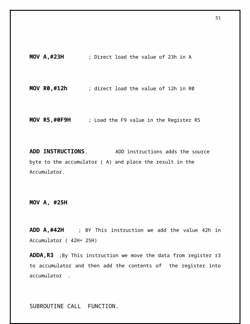
MOV A,#23H ; Direct load the value of 23h in A
MOV R0,#12h ; direct load the value of 12h in R0
MOV R5,#0F9H ; Load the F9 value in the Register R5
ADD INSTRUCTIONS. ADD instructions adds the source byte to the accumulator
( A) and place the result in the Accumulator.
MOV A, #25H
ADD A,#42H ; BY This instruction we add the value 42h in Accumulator ( 42H+ 25H)
ADDA,R3 ;By This instruction we move the data from register r3 to accumulator and then
add the contents of the register into accumulator .
38
SUBROUTINE CALL FUNCTION.
ACALL,TARGET ADDRESS
By This instruction we call subroutines with a target address within 2k bytes from the current
program counter.
LCALL, TARGET ADDRESS.
ACALL is a limit for the 2 k byte program counter, but for upto 64k byte we use LCALL
instructions.. Note that LCALL is a 3 byte instructions. ACALL is a two byte instructions.
AJMP TARGET ADDRESS.
This is for absolute jump
AJMP stand for absolute jump. It transfers program execution to the target address
unconditionally. The target address for this instruction must be within 2 k
byte of program memory.
LJMP is also for absolute jump. It transfers program execution to the target address
unconditionally. This is a 3 byte instructions LJMP jump to any address
within 64 k byte location.
39
Arithmetic Instructions:
ANL test-byte, source-byte
This performs a logical AND on the operands, bit by bit, storing the result in the destination.
Notice that both the source and destination values are byte –size only
DIV AB
This instruction divides a byte accumulator by the byte in register B. It is assumed that both
register A and B contain an unsigned byte. After the division the quotient will be in register A
and the remainder in register B.
TMOD ( TIMER MODE ) REGISTER
Both timer is the 89c51 share one register TMOD. 4 LSB bit for the timer 0 and 4 MSB for the
timer 1.
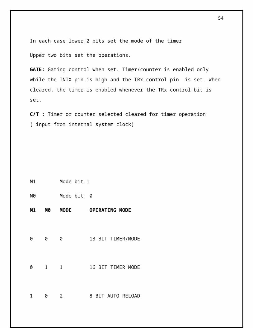
In each case lower 2 bits set the mode of the timer
Upper two bits set the operations.
GATE: Gating control when set. Timer/counter is enabled only while the INTX pin is high and
the TRx control pin is set. When cleared, the timer is enabled whenever the TRx control bit is
set.
C/T : Timer or counter selected cleared for timer operation ( input from internal system clock)
40
M1 Mode bit 1
M0 Mode bit 0
M1 M0 MODE OPERATING MODE
0 0 0 13 BIT TIMER/MODE
0 1 1 16 BIT TIMER MODE
1 0 2 8 BIT AUTO RELOAD
1 1 3 SPLIT TIMER MODE
PSW ( PROGRAM STATUS WORD)
CY PSW.7 CARRY FLAG
AC PSW.6 AUXILIARY CARRY
41
F0 PSW.5 AVAILABLE FOR THE USER FRO GENERAL PURPOSE
RS1 PSW.4 REGISTER BANK SELECTOR BIT 1
RS0 PSW.3 REGISTER BANK SELECTOR BIT 0
0V PSW.2 OVERFLOW FLAG
-- PSW.1 USER DEFINABLE BIT
P PSW.0 PARITY FLAG SET/CLEARED BY HARDWARE
PCON REGISATER ( NON BIT ADDRESSABLE)
If the SMOD = 0 ( DEFAULT ON RESET)
TH1 = CRYSTAL FREQUENCY
256---- ____________________
384 X BAUD RATE
If the SMOD IS = 1
CRYSTAL FREQUENCY
TH1 = 256--------------------------------------
192 X BAUD RATE
42
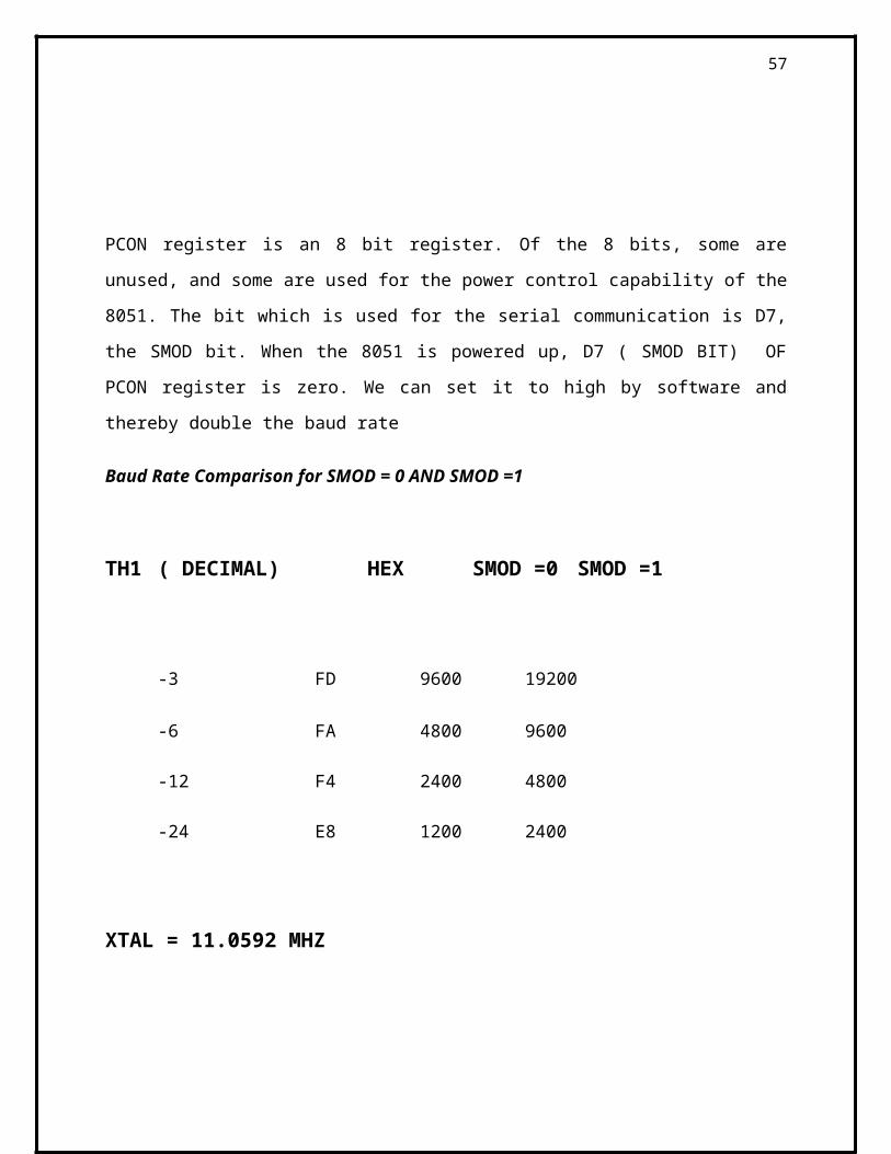
There are two ways to increase the baud rate of data transfer in the 8051
1. To use a higher frequency crystal
2. To change a bit in the PCON register
PCON register is an 8 bit register. Of the 8 bits, some are unused, and some are used for the
power control capability of the 8051. The bit which is used for the serial communication is D7,
the SMOD bit. When the 8051 is powered up, D7 ( SMOD BIT) OF PCON register is zero. We
can set it to high by software and thereby double the baud rate
Baud Rate Comparison for SMOD = 0 AND SMOD =1
TH1 ( DECIMAL) HEX SMOD =0 SMOD =1
-3 FD 9600 19200
-6 FA 4800 9600
-12 F4 2400 4800
-24 E8 1200 2400
XTAL = 11.0592 MHZ
43

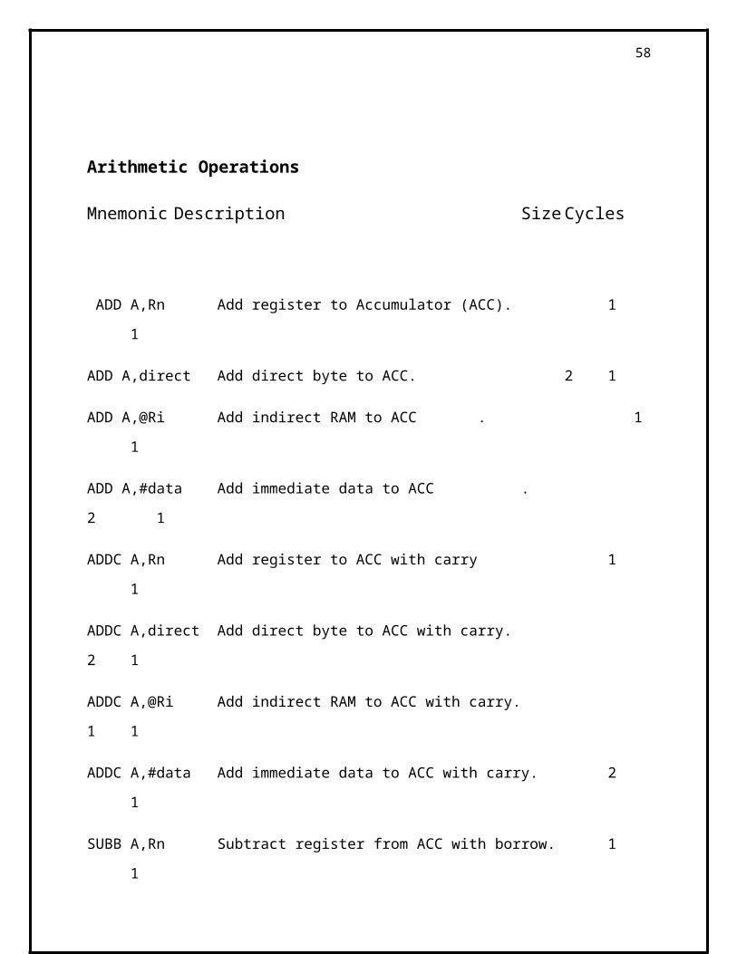
Arithmetic Operations
Mnemonic Description Size Cycles
ADD A,Rn Add register to Accumulator (ACC). 1 1
ADD A,direct Add direct byte to ACC. 2 1
ADD A,@Ri Add indirect RAM to ACC . 1 1
ADD A,#data Add immediate data to ACC . 2 1
ADDC A,Rn Add register to ACC with carry 1 1
ADDC A,direct Add direct byte to ACC with carry. 2 1
ADDC A,@Ri Add indirect RAM to ACC with carry. 1 1
ADDC A,#data Add immediate data to ACC with carry. 2 1
SUBB A,Rn Subtract register from ACC with borrow. 1 1
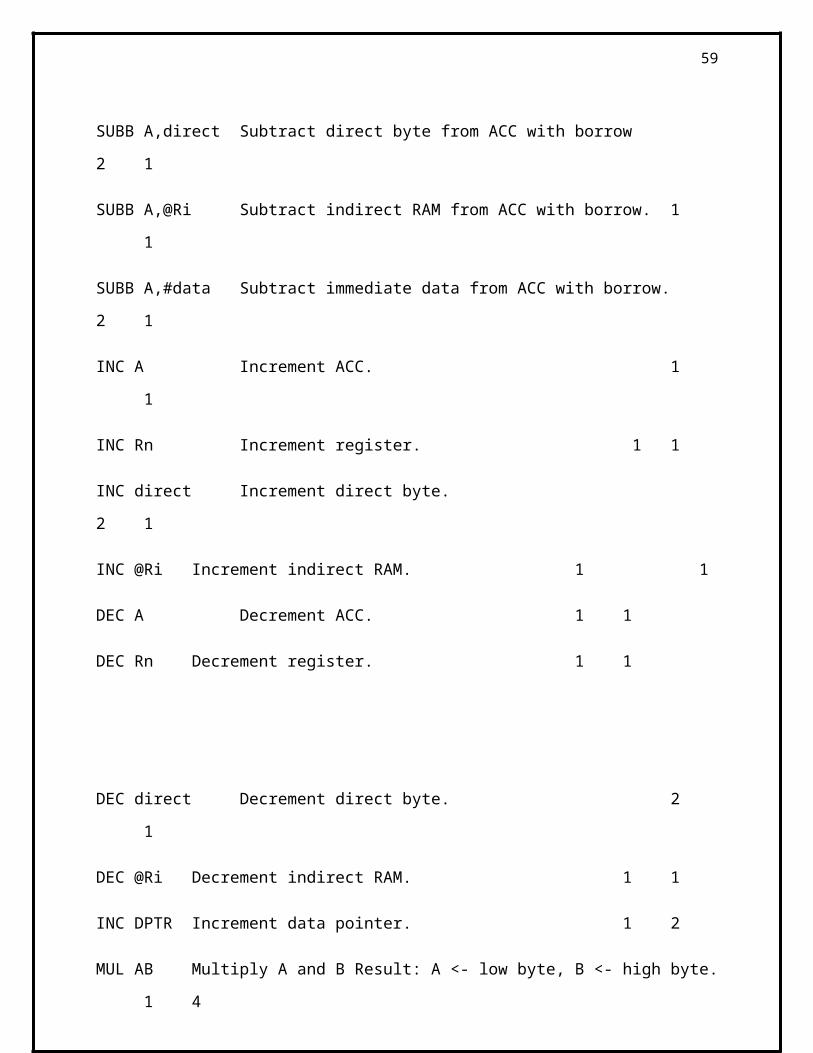
SUBB A,direct Subtract direct byte from ACC with borrow 2 1
SUBB A,@Ri Subtract indirect RAM from ACC with borrow. 1 1
SUBB A,#data Subtract immediate data from ACC with borrow. 2 1
INC A Increment ACC. 1 1
INC Rn Increment register. 1 1
INC direct Increment direct byte. 2 1
INC @Ri Increment indirect RAM. 1 1
DEC A Decrement ACC. 1 1
DEC Rn Decrement register. 1 1
44

DEC direct Decrement direct byte. 2 1
DEC @Ri Decrement indirect RAM. 1 1
INC DPTR Increment data pointer. 1 2
MUL AB Multiply A and B Result: A <- low byte, B <- high byte. 1 4
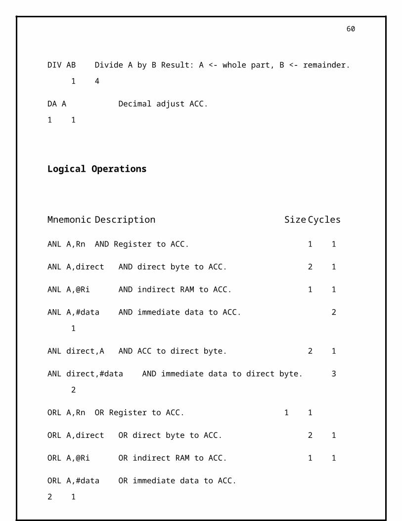
DIV AB Divide A by B Result: A <- whole part, B <- remainder. 1 4
DA A Decimal adjust ACC. 1 1
Logical Operations
Mnemonic Description Size Cycles
ANL A,Rn AND Register to ACC. 1 1
ANL A,direct AND direct byte to ACC. 2 1
ANL A,@Ri AND indirect RAM to ACC. 1 1
ANL A,#data AND immediate data to ACC. 2 1
ANL direct,A AND ACC to direct byte. 2 1
ANL direct,#data AND immediate data to direct byte. 3 2
ORL A,Rn OR Register to ACC. 1 1
ORL A,direct OR direct byte to ACC. 2 1
ORL A,@Ri OR indirect RAM to ACC. 1 1
ORL A,#data OR immediate data to ACC. 2 1
ORL direct,A OR ACC to direct byte. 2 1
45

ORL direct,#data OR immediate data to direct byte. 3 2
XRL A,Rn Exclusive OR Register to ACC. 1 1
XRL A,direct Exclusive OR direct byte to ACC. 2 1
XRL A,@Ri Exclusive OR indirect RAM to ACC. 1 1
XRL A,#data Exclusive OR immediate data to ACC. 2 1
XRL direct,A Exclusive OR ACC to direct byte. 2 1
XRL direct,#data XOR immediate data to direct byte. 3 2
CLR A Clear ACC (set all bits to zero). 1 1
CPL A Compliment ACC. 1 1
RL A Rotate ACC left. 1 1
RLC A Rotate ACC left through carry. 1 1
RR A Rotate ACC right. 1 1
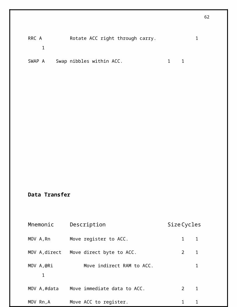
RRC A Rotate ACC right through carry. 1 1
SWAP A Swap nibbles within ACC. 1 1
46
Data Transfer
Mnemonic Description Size Cycles
MOV A,Rn Move register to ACC. 1 1
MOV A,direct Move direct byte to ACC. 2 1
MOV A,@Ri Move indirect RAM to ACC. 1 1
MOV A,#data Move immediate data to ACC. 2 1
MOV Rn,A Move ACC to register. 1 1
MOV Rn,direct Move direct byte to register. 2 2
MOV Rn,#data Move immediate data to register. 2 1
MOV direct,A Move ACC to direct byte. 2 1
MOV direct,Rn Move register to direct byte. 2 2
MOV direct,direct Move direct byte to direct byte. 3 2
MOV direct,@Ri Move indirect RAM to direct byte. 2 2
MOV direct,#data Move immediate data to direct byte. 3 2
MOV @Ri,A Move ACC to indirect RAM. 1 1
MOV @Ri,direct Move direct byte to indirect RAM. 2 2
MOV @Ri,#data Move immediate data to indirect RAM. 2 1
MOV DPTR,#data16 Move immediate 16 bit data to data pointer 3 2
MOVC A,@A+DPTR Move code byte relative to DPTR to ACC (16 bit address).
1 2
47
MOVC A,@A+PC Move code byte relative to PC to ACC (16 bit address).
1 2
MOVX A,@Ri Move external RAM to ACC (8 bit address). 1 2
MOVX A,@DPTR Move external RAM to ACC (16 bit address). 1 2
MOVX @Ri,A Move ACC to external RAM (8 bit address). 1 2
MOVX @DPTR,A Move ACC to external RAM (16 bit address). 1 2
PUSH direct Push direct byte onto stack. 2 2
POP direct Pop direct byte from stack. 2 2
XCH A,Rn Exchange register with ACC. 1 1
XCH A,direct Exchange direct byte with ACC. 2 1
XCH A,@Ri Exchange indirect RAM with ACC. 1 1
XCHD A,@Ri Exchange low order nibble of indirect
RAM with low order nibble of ACC 1 1
Boolean Variable Manipulation
Mnemonic Description Size Cycles
CLR C Clear carry flag. 1 1
CLR bit Clear direct bit. 2 1
SETB C Set carry flag. 1 1
SETB bitSet direct bit 2 1
CPL C Compliment carry flag. 1 1
48
CPL bit Compliment direct bit. 2 1
ANL C,bit AND direct bit to carry flag. 2 2
ANL C,/bit AND compliment of direct bit to carry. 2 2
ORL C,bit OR direct bit to carry flag. 2 2
ORL C,/bit OR compliment of direct bit to carry. 2 2
MOV C,bit Move direct bit to carry flag. 2 1
MOV bit,C Move carry to direct bit. 2 2
JC rel Jump if carry is set. 2 2
JNC rel Jump if carry is not set. 2 2
JB bit,rel Jump if direct bit is set. 3 2
JNB bit,rel Jump if direct bit is not set. 3 2
JBC bit,rel Jump if direct bit is set & clear bit. 3 2
Program Branching
Mnemonic Description Size Cycles
ACALL addr11 Absolute subroutine call. 2 2
LCALL addr16 Long subroutine call. 3 2
RET Return from subroutine. 1 2
49

RETI Return from interrupt. 1 2
AJMP addr11 Absolute jump. 2 2
LJMP addr16 Long jump. 3 2
SJMP rel Short jump (relative address). 2 2
JMP @A+DPTR Jump indirect relative to the DPTR 1 2
JZ rel Jump relative if ACC is zero. 2 2
JNZ rel Jump relative if ACC is not zero. 2 2
CJNE A,direct,rel Compare direct byte to ACC and jump if not equal.
3 2
CJNE A,#data,rel Compare immediate byte to ACC and jump if not equal.
3 2
CJNE Rn,#data,rel Compare immediate byte to register and jump if not equal.
3 2
50
CJNE @Ri,#data,rel Compare immediate byte to indirect and jump if not equal.
3 2
DJNZ Rn,rel Decrement register and jump if not zero. 2 2
DJNZ direct,rel Decrement direct byte and jump if not zero. 3 2
IE ( INTERRUPT ENABLE REGISTOR)
EA IE.7 Disable all interrupts if EA = 0, no interrupts is acknowledged
If EA is 1, each interrupt source is individually enabled or disabled
By sending or clearing its enable bit.
51

IE.6 NOT implemented
ET2 IE.5 enables or disables timer 2 overflag in 89c52 only
ES IE.4 Enables or disables all serial interrupt
ET1 IE.3 Enables or Disables timer 1 overflow interrupt
EX1 IE.2 Enables or disables external interrupt
ET0 IE.1 Enables or Disables timer 0 interrupt.
EX0 IE.0 Enables or Disables external interrupt 0
INTERRUPT PRIORITY REGISTER
52

If the bit is 0, the corresponding interrupt has a lower priority and if the bit is 1 the corresponding
interrupt has a higher priority
IP.7 Not Implemented, Reserved For Future Use.
IP.6 Not Implemented, Reserved For Future Use
PT2 IP.5 Define the Timer 2 Interrupt Priority Level
PS IP.4 Defines the Serial Port Interrupt Priority Level
PT1 IP.3 Defines the Timer 1 Interrupt Priority Level
PX1 IP.2 Defines External Interrupt 1 Priority Level
PT0 IP.1 Defines the Timer 0 Interrupt Priority Level
PX0 IP.0 Defines the External Interrupt 0 Priority Level
53
SCON: SERIAL PORT CONTROL REGISTER , BIT ADDRESSABLE
SCON
SM0 : SCON.7 Serial Port mode specifier
SM1 : SCON.6 Serial Port mode specifier
SM2 : SCON.5
REN : SCON.4 Set/cleared by the software to Enable/disable reception
TB8 : SCON.3 the 9th bit that will be transmitted in modes 2 and 3, Set/cleared
By software
RB8 : SCON.2 In modes 2 &3, is the 9th data bit that was received. In mode 1,
If SM2 = 0, RB8 is the stop bit that was received. In mode 0
RB8 is not used
54

T1 : SCON.1 Transmit interrupt flag. Set by hardware at the end of the 8th bit
Time in mode 0, or at the beginning of the stop bit in the other
Modes. Must be cleared by software
R1 SCON.0 Receive interrupt flag. Set by hardware at the end of the 8th bit
Time in mode 0, or halfway through the stop bit time in the other
Modes. Must be cleared by the software.
55

TCON TIMER COUNTER CONTROL REGISTER
This is a bit addressable
TF1 TCON.7 Timer 1 overflow flag. Set by hardware when the Timer/Counter 1
Overflows. Cleared by hardware as processor
TR1 TCON.6 Timer 1 run control bit. Set/cleared by software to turn Timer
Counter 1 On/off
TF0 TCON.5 Timer 0 overflow flag. Set by hardware when the timer/counter 0
Overflows. Cleared by hardware as processor
TR0 TCON.4 Timer 0 run control bit. Set/cleared by software to turn timer
Counter 0 on/off.
IE1 TCON.3 External interrupt 1 edge flag
ITI TCON.2 Interrupt 1 type control bit
IE0 TCON.1 External interrupt 0 edge
IT0 TCON.0 Interrupt 0 type control bit.
56
JC TARGET
JUMP TO THE TARGET IF CY FLAG =1
JNC TARGET
JUMP TO THE TARGET ADDRESS IF CY FLAG IS = 0
INSTRUCTIONS RELASTED TO JUMP WITH ACCUMULATOR
JZ TARGET
JUMP TO TARGET IF A = 0
JNZ TARGET
JUMP IF ACCUMULATOR IS NOT ZERO
This instruction jumps if register A has a value other than zero
INSTRUCTIONS RELATED TO THE ROTATE
RL A
ROTATE LEFT THE ACCUMULATOR
BY This instruction we rotate the bits of A left. The bits rotated out of A are rotated back into A
at the opposite end
57
RR A
By this instruction we rotate the contents of the accumulator from right to left from LSB to MSB
RRC A
This is same as RR A but difference is that the bit rotated out of register first enter in to carry and
then enter into MSB
RLC A
Rotate Left through carry.
Same as above but shift the data from MSB to carry and carry to LSB
RET
This is return from subroutine. This instruction is used to return from a subroutine previously
entered by instructions LCALL and ACALL.
RET1
This is used at the end of an interrupt service routine. We use this instruction after interrupt
routine,
PUSH.
This copies the indicated byte onto the stack and increments SP by one. This instruction supports
only direct addressing mode.
POP.
58
POP FROM STACK.
This copies the byte pointed to be SP to the location whose direct address is indicated, and
decrements SP by 1. Notice that this instruction supports only direct addressing mode.
59
Power Supply Circuit:-
Transformer:-
Transformer works on the principle of mutual inductance. We know that if two coils or windings
are placed on the core of iron, and if we pass alternating current in one winding, back emf or
induced voltage is produced in the second winding. We know that alternating current always
changes with the time. So if we apply AC voltage across one winding, a voltage will be induced
in the other winding. Transformer works on this same principle. It is made of two windings
wound around the same core of iron. The winding to which AC voltage is applied is called
primary winding. The other winding is called as secondary winding Voltage and current
relationship:
Let V1 volts be input alternating voltage applied to primary winding. I1 Amp is input alternating
current through primary winding. V2 volt is output alternating voltage produced in the secondary.
I2 amp be the current flowing through the secondary.
Then relationship between input and output voltages is given by
V1/V2 = N1/N2
Relationship between input and output currents is
I1/I2 = N2/N1
(Where N1 is no. of turns of coil in primary and N2 is number of turns in secondary )
We know that Power = Current X Voltage. It is to be noted that input power is equal to output
power. Power is not changed. If V2 is greater than V1, then I2 will be less than I1. This type of
transformer is called as step up transformer. If V1 is greater than V2, then I1 will be less than I2.
This type of transformer is called as step down transformer.
For step up transformer, N2>N1, i.e., number of turns of secondary winding is more than those in
primary.For step down transformer, N1>N2, i.e., numbers of turns of primary winding is more
than those in secondary.
60

7. Code for Microcontroller:
org 0000h
home: jnb p1.0,car_stop
jb p1.1,car_move
sjmp home
car_stop: setb P2.0
setb P2.1
sjmp home
car_move: setb P2.0
clr P2.1
sjmp home
END
61
8. References
• Paper Driver Assistance Systems for Safety and Comfort Werner Uhler, Hans-Joerg Mathony,
Peter M. Knoll Robert Bosch GmbH, Driver Assistance Systems, Leonberg, Germany
• 11 Aachener Kolloquium Fahrzeug- und Motorentechnik 2002 Low-Cost Long-Range- Radar
for Future Driver Assistance Systems Dr. Götz K&umul;hnle, Dipl.-Ing. (FH) Hermann Mayer,
Dr. Herbert Olbrich Dipl.-Ing. Hans-Christian Swoboda, Robert Bosch GmbH, Stuttgart,
Germany
• AutoTechnology, 4/2003 Low-Cost Long-Range Radar for Future Driver Assistance Systems
Dr. Götz Kühnle, Dipl.-Ing. (FH) Hermann Mayer, Dr. Herbert Olbrich, Dr. Wolf Steffens Dipl.-
Ing. Hans-Christian Swoboda, Robert Bosch GmbH
• Mitsubishi Electric, Automobile - Human Technology Edition, VOL. 94/JUN. 2001
Automobile - Human Technology Edition Millimeter - Wave Radar Technology for Automotive
Application Shinichi Honma, Naohisa Uehara
• Paper Waveform Design Principles for Automotive Radar Systems Hermann Rohling, Marc-
Michael Meinecke Technical University of Hamburg-Harburg, Germany Department of
Telecommunications
• www.medhaavi.com (Medhaavi Embedded Systems, Hoshiarpur)
62


![ACC Optim Report[1]](https://static.fdocuments.us/doc/165x107/577d23a01a28ab4e1e9a511b/acc-optim-report1.jpg)