
Report 95 -011 de Havilland DHC -8, ZK -NEY near ... · near Palmerston North 9 June 1995 Abstract...
137
Report 95-011 de Havilland DHC-8, ZK-NEY controlled flight into terrain near Palmerston North 9 June 1995 Abstract At approximately 0922 hours on Friday 9 June 1995 a de Havilland DHC-8 aircraft, ZK-NEY, collided with the terrain some 16 km east of Palmerston North Aerodrome while carrying out an instrument approach. One crew member and three passengers lost their lives and two crew members and 12 passengers were seriously injured in the accident. The causal factors were: the Captain not ensuring the aircraft intercepted and maintained the approach profile during the conduct of the non-precision instrument approach, the Captain’s perseverance with his decision to get the undercarriage lowered without discontinuing the instrument approach, the Captain’s distraction from the primary task of flying the aircraft safely during the First Officer’s endeavours to correct an undercarriage malfunction, the First Officer not executing a Quick Reference Handbook procedure in the correct sequence, and the shortness of the ground proximity warning system warning. The safety issues discussed are: the need for pilots to continue to monitor the safe conduct of the flight while dealing with any non-normal system operation, the desirability of the Captain assuming manipulative control of the aircraft in the event of an abnormal situation arising, the efficacy of the operator’s follow-up on their decision not to modify the aircraft’s undercarriage, the efficacy of the operator’s flight safety programme, the design of the Quick Reference Handbook checklists, the limitations of the knowledge-based crew resource management training, the Civil Aviation Authority’s shortage of audit staff available to detect weaknesses in operating procedures during its audits, the standard of performance of the aircraft’s ground proximity warning system, the completeness of the advice to passengers on the safety equipment carried in an aircraft and the implementation of a minimum safe altitude warning system for the Air Traffic Control radar.
Transcript of Report 95 -011 de Havilland DHC -8, ZK -NEY near ... · near Palmerston North 9 June 1995 Abstract...

Report 95-011
de Havilland DHC-8, ZK-NEY
controlled flight into terrain
near Palmerston North
9 June 1995
Abstract
At approximately 0922 hours on Friday 9 June 1995 a de Havilland DHC-8 aircraft, ZK-NEY, collided with the terrain some 16 km east of Palmerston North Aerodrome while carrying out an instrument approach. One crew member and three passengers lost their lives and two crew members and 12 passengers were seriously injured in the accident. The causal factors were: the Captain not ensuring the aircraft intercepted and maintained the approach profile during the conduct of the non-precision instrument approach, the Captain’s perseverance with his decision to get the undercarriage lowered without discontinuing the instrument approach, the Captain’s distraction from the primary task of flying the aircraft safely during the First Officer’s endeavours to correct an undercarriage malfunction, the First Officer not executing a Quick Reference Handbook procedure in the correct sequence, and the shortness of the ground proximity warning system warning. The safety issues discussed are: the need for pilots to continue to monitor the safe conduct of the flight while dealing with any non-normal system operation, the desirability of the Captain assuming manipulative control of the aircraft in the event of an abnormal situation arising, the efficacy of the operator’s follow-up on their decision not to modify the aircraft’s undercarriage, the efficacy of the operator’s flight safety programme, the design of the Quick Reference Handbook checklists, the limitations of the knowledge-based crew resource management training, the Civil Aviation Authority’s shortage of audit staff available to detect weaknesses in operating procedures during its audits, the standard of performance of the aircraft’s ground proximity warning system, the completeness of the advice to passengers on the safety equipment carried in an aircraft and the implementation of a minimum safe altitude warning system for the Air Traffic Control radar.

The Transport Accident Investigation Commission is an independent Crown entity established to determine the circumstances and causes of accidents and incidents with a view to avoiding similar occurrences in the future. Accordingly it is inappropriate that reports should be used to assign fault or blame or determine liability, since neither the investigation nor the reporting process has been undertaken for that purpose. The Commission may make recommendations to improve transport safety. The cost of implementing any recommendation must always be balanced against its benefits. Such analysis is a matter for the regulator and the industry. These reports may be reprinted in whole or in part without charge, providing acknowledgement is made to the Transport Accident Investigation Commission.
Transport Accident Investigation Commission P O Box 10-323, Wellington, New Zealand
Phone +64 4 473 3112 Fax +64 4 499 1510 E-mail: [email protected] Web site: www.taic.org.nz


2

3
Table of Contents
1. Factual Information 7
1.1 History of the flight 7
1.2 Injuries to persons 8
1.3 Damage to aircraft 8
1.4 Other damage 8
1.5 Personnel information 8
1.6 Aircraft information 10
1.7 Meteorological information 23
1.8 Aids to navigation 26
1.9 Communications 29
1.10 Aerodrome information 31
1.11 Flight recorders 31
1.12 Wreckage and impact information 33
1.13 Medical and pathological information 37
1.14 Fire 39
1.15 Survival aspects 40
1.16 Tests and research 44
1.17 Organisational and management information 49
1.18 Additional information 59
2. Analysis 70
3. Findings 89
4. Safety Recommendations 93
Appendices
Appendix A DFDR Readouts 103
Appendix B CFIT Checklist 105
Appendix C Edited Extracts of CVR Transcript 109
Glossary 133

4
ZK-NEY looking aft
ZK-NEY right side

5
Transport Accident Investigation Commission
Aircraft Accident Report No. 95-011
Aircraft type, serial number and registration:
de Havilland DHC-8-102 ,055, ZK-NEY
Number and type of engines:
Two Pratt and Whitney PW-120A
Year of manufacture:
1986
Date and time:
9 June 1995, 0922 hours *
Location:
16 km east of Palmerston North Aerodrome Latitude: 40°20′S Longitude: 175°48′E
Operator:
Ansett New Zealand Limited
Type of flight:
Scheduled Air Transport, Passenger
Persons on board:
Crew: 3 Passengers: 18
Injuries:
Crew: 1 Fatal 2 Serious Passengers: 3 Fatal 12 Serious 3 Minor/none
Nature of damage:
Aircraft destroyed
Pilot-in-Command’s Licence:
Airline Transport Pilot Licence (Aeroplane)
Pilot-in-Command’s Age:
40
Pilot-in-Command’s Total Flying Experience:
7765 hours (273 on type)
Investigator in Charge:
R Chippindale
* All times in this report are in NZST (UTC + 12 hours)

6
+

7
1. Factual Information 1.1 History of the flight 1.1.1 At 0817 hours on Friday 9 June 1995 ZK-NEY, a de Havilland DHC-8 (Dash 8) aircraft,
departed Auckland as scheduled Ansett New Zealand Flight 703 bound for Palmerston North. Aboard were a crew of three and 18 passengers.
1.1.2 To the north of Palmerston North the pilots briefed themselves for a VOR/DME1 approach to
runway 07 which was the approach they preferred. Subsequently Air Traffic Control specified the VOR/DME approach for runway 25, due to departing traffic, and the pilots re-briefed for that instrument approach without further ado. The IMC involved flying in and out of stratiform cloud, but continuous cloud prevailed during most of the approach.
1.1.3 The aircraft was flown accurately to join the 14 nm DME arc (see Figure 1) and thence turned
right and intercepted the final approach track of 250° M to the Palmerston North VOR. During the right turn, to intercept the inbound approach track, the aircraft’s power levers were retarded to FLIGHT IDLE and shortly afterwards the First Officer advised the Captain “.... 12 DME looking for 4000 (feet)”. The final approach track was intercepted at approximately 13 DME and 4700 feet, and the First Officer advised Ohakea Control “Ansett 703” was “established inbound”.
1.1.4 Just prior to 12 miles DME the Captain called “Gear down”. The First Officer asked him to
repeat what he had said and then responded “OK selected and on profile, ten - sorry hang on 10 DME we’re looking for four thousand aren’t we so - a fraction low”. The Captain responded, “Check, and Flap 15”. This was not acknowledged but the First Officer said, “Actually no, we’re not, ten DME we’re..... (The Captain whistled at this point) look at that”. The Captain said, “I don’t want that.” and the First Officer responded, “No, that’s not good is it, so she’s not locked, so Alternate Landing Gear...?” The Captain acknowledged, “Alternate extension, you want to grab the QRH?” After the First Officer’s “Yes”, the Captain continued, “You want to whip through that one, see if we can get it out of the way before it’s too late.”
1.1.5 The Captain then stated, “I’ll keep an eye on the aeroplane while you’re doing that.” 1.1.6 The First Officer located the appropriate “Landing Gear Malfunction Alternate Gear Extension”
checklist in Ansett New Zealand’s Quick Reference Handbook (QRH) and began reading it. He started with the first check on the list but the Captain told him to skip through some checks. The First Officer responded to this instruction and resumed reading and carrying out the necessary actions. It was the operator’s policy that all items on the QRH checklists be actioned, or proceeded through, as directed by the Captain.
1.1.7 The First Officer carried out the checklist correctly up to and including the item:
L/G ALTERNATE RELEASE DOOR - OPEN FULLY & LEAVE OPEN
to which he commented “which it is.” However he then continued “and insert this handle and operate until main gear locks, actually nose gear.”
1 For definition of abbreviations throughout, see the Glossary at the end of this report.
8
1.1.8 The correct sequence was:
L/G ALTERNATE RELEASE DOOR OPEN FULLY & LEAVE OPEN
MAIN GEAR RELEASE HANDLE PULL FULLY DOWN L/G ALTERNATE EXTENSION DOOR OPEN FULLY
& LEAVE OPEN
Insert pump handle and operate until main landing gear locks down........
1.1.9 The Captain noticed the First Officer’s actions and advised “You’re supposed to pull the handle....”
1.1.10 The First Officer then pulled the Main Gear Release Handle and had just finished saying, “Yeah
that’s pulled here we go.”, when the GPWS’s audio alarm sounded. 1.1.11 Between four and a half and four point eight seconds later the aircraft collided with the terrain. 1.1.12 One crew member and two passengers were killed during the impact sequence. Another
passenger died 12 days later from burns received after he had escaped from the aircraft’s cabin. He was waiting alongside the aircraft’s right engine when an existing minor fire developed and engulfed him. Two crew members and 12 passengers suffered serious injuries and three passengers escaped with minor injuries.
1.2 Injuries to persons 1.2.1 Crew Passengers Others
Fatal 1 3 - Serious 2 12 - Minor/None - 3 -
1.3 Damage to aircraft 1.3.1 The aircraft was destroyed. 1.4 Other damage 1.4.1 Three sheep were killed by the aircraft wreckage and an area of pasture was spoiled by the
impact damage, fuel contamination and fire. 1.5 Personnel information 1.5.1 Captain Male, aged 40 years
Licence: Airline Transport Pilot Licence (Aeroplane) Aircraft Ratings: Boeing 737-200, BAe 146, DHC-8 and SA 227 Medical Certificate: Class 1, Valid until 17 May 1996 Last Instrument Rating check: 7 January 1995 Last Regulation 76 check: 13 March 1995

9
Last route check: 13 March 1995 Flying experience: Total all types: 7765 hours
Total on type: 273 hours Total all types previous 90 days: 173 hours Total on type previous 90 days: 172 hours
Duty time: 5.2 hours Rest period before duty: 10 hours
1.5.2 The Captain had been employed by Ansett New Zealand since April 1989, where he had flown
3740 hours on line operations as a First Officer on B737 and BAe 146 types up to 30 October 1994. Previous experience in two-pilot crew operations included 500 hours on Metroliner aircraft, of which 100 hours was in command. He had completed sessions of CRM Training at the Recurrent Training School on 9/10 September 1992, 16/17 March 1994, 1/2 November 1994 and 21 December 1994, and he had participated in five LOFT exercises as First Officer in the BAe 146 simulator flying as a First Officer in the right-hand seat.
1.5.3 He had no experience on the Dash 8 aircraft prior to October 1994. In preparation for his
command of the Dash 8 he undertook and passed the conversion training for the type followed by 103 hours of command training with a training captain before his “check to line” on 13 March 1995. This included a base check on 11 March 1995 and line checks with different check and training Captains on 13 March and 14 May 1995. As a result his command and leadership ability was assessed as above average, and workload management and distraction avoidance as average.
1.5.4 First Officer Male, aged 33 years
Licence: Airline Transport Pilot Licence (Aeroplane) Aircraft Ratings: DHC-8, DHC-6, BN2, EMB-110 and B-200 Medical Certificate: Class 1, Valid until 29 August 1995 Last Instrument Rating check: 20 November 1994 Last Regulation 76 check: 30 April 1995 Last route check: 30 April 1995 ATPL issue Flight Test: 30 April 1995 Flying experience: Total all types: 6460 hours
Total on type: 341 hours Total all types previous 90 days: 162 hours Total on type previous 90 days: 162 hours
Duty time: 5.2 hours Rest period before duty: More than 48 hours
1.5.5 The First Officer was employed by Ansett New Zealand in November 1994 after he had
completed his Dash 8 ground course. For five years before that he had flown DHC-6, Britten-Norman BN2, Embraer 110 and Beech 200 types on airline passenger services in Papua New Guinea, logging 4000 hours predominantly on single pilot IFR operations. He had little two-pilot crew experience before joining Ansett. He had attended one four-hour session of Ansett New Zealand’s CRM Training during his Dash 8 ground course.

10
1.6 Aircraft information 1.6.1 ZK-NEY was a de Havilland Canada DHC-8 (Dash 8) Series 102 Aircraft, Constructor’s
Number 055, which had been manufactured in Canada in 1986. 1.6.2 The aircraft was registered to Ansett New Zealand Limited in December 1986. It was issued
with a temporary New Zealand Certificate of Airworthiness (C of A) to facilitate a ferry flight to New Zealand, and was subsequently granted a New Zealand C of A in the Standard Category in July 1987. This C of A was non-terminating provided the aircraft was maintained in accordance with the Ansett New Zealand Limited Engineering Procedures Manual and subsidiary Manuals authorised therein.
1.6.3 ZK-NEY entered service soon after its arrival in New Zealand. The aircraft had been maintained
since that time by Ansett New Zealand Limited Engineering. A review of the Maintenance Log showed that all significant defects on ZK-NEY were recorded as having been investigated and rectified or deferred as appropriate, in conjunction with the airline’s normal engineering procedure, prior to the occurrence of the accident. Relevant entries had been included in the Maintenance Status Section of the Maintenance Log carried on the aircraft. A six-monthly Maintenance Review was also carried out between 15 May and 18 May 1995.
1.6.4 The last Maintenance Release was issued on 19 May 1995, and was valid to 20 November 1995.
On 6 June 1995 the Ansett New Zealand Limited Engineering Quality Assurance Manager completed an audit of this maintenance and considered it complied with the maintenance, modification and inspection requirements of the CAA and Ansett New Zealand Limited.
1.6.5 Routine overnight servicing was carried out on 8 June 1995 (the night before the accident). At
this time, ZK-NEY had accumulated a total of 22 154 hours in service, and 24 976 cycles. 1.6.6 During this servicing period an investigation was made into a reported fuel seepage, within the
right engine nacelle’s tail cone, which had been observed when the aircraft was being refuelled earlier in the day. The seepage was only evident under the 45 psi (310 kPa) refuelling pressure. No seepage occurred under simulated “in flight” conditions. The reported discrepancy and deferral action, taken in accordance with the relevant provisions of the DHC-8 Maintenance Manual, were recorded in the aircraft’s Maintenance Status Log.
1.6.7 Two Pratt and Whitney PW 120A engines were installed in ZK-NEY.
The left engine was serial number PC-E120199. 18 926 hours and 21 495 cycles had been recorded for this engine since new. The right engine was serial number PC-E120206. 14 908 hours and 16 601 cycles had been recorded for this engine since new.
1.6.8 Hamilton Standard propellers, type 14SF-7 were fitted.
The left propeller was serial number 870826 with 12 011 hours total time and 7974 hours recorded since overhaul. The right propeller was serial number 870521 with 8723 hours total time and 486 hours recorded since overhaul.
1.6.9 The propeller units comprised four blades of composite construction mounted on forged aluminium spars.

11
Undercarriage details 1.6.10 The Dash 8’s undercarriage was a retractable tricycle-type incorporating air/oil shock struts with
dual wheel assemblies fitted to each main undercarriage leg and the nosewheel leg. 1.6.11 The nose undercarriage was mounted in the front fuselage ahead of the flight deck area and
retracted forward into the unpressurised nose section. 1.6.12 The left and right main undercarriage legs were attached to the respective engine nacelle
structures. The main undercarriage retracted rearwards into wheel wells located in the nacelles. 1.6.13 Normal operation of the undercarriage utilised hydraulic power for retraction and extension. An
undercarriage control panel located on the upper right of the central instrument panel incorporated a selector lever providing two positions - “UP” or “DOWN”.
1.6.14 Positive mechanical locking of the main undercarriage was provided in the “UP” and “DOWN”
positions. Indicators were provided to identify the position of the undercarriage and if the undercarriage doors were not in the correct position for the sequence selected. A non-cancellable audible warning device was provided to warn the flight crew if the undercarriage was not in a fully down and locked position when the engine power levers were retarded to a position suitable for landing and the airspeed was less than 130 knots indicated.
1.6.15 An alternative means of extending the main undercarriage was provided which involved
mechanical actuation of the uplock to unlock the undercarriage legs thereby permitting a free-fall. Once the uplock was released the main undercarriage locking could be assisted by an independent hydraulic system operated by a hand pump located on the flight deck floor2.
1.6.16 Each main undercarriage unit, when retracted, was completely enclosed within the nacelle by
three doors. The main undercarriage door actuation was powered hydraulically and so controlled that the wheel bay and lower strut doors were closed when the undercarriage was fully down.
1.6.17 During main undercarriage extension a sequencing system opened the nacelle doors in the
appropriate order and subsequently closed the rear and centre doors. The front doors remained open with the undercarriage in the “DOWN” position.
Relevant aspects of the undercarriage system
Extension
1.6.18 Normal extension of the undercarriage was initiated by a “DOWN” selection of the undercarriage control lever. The lever operated a switch to energise the down solenoid of the undercarriage selector valve. As soon as the down line was pressurised, the de-energised solenoid sequence valve directed hydraulic pressure to the open side of the rear and centre door actuator and the open side of the front door actuator was connected directly to the down hydraulic line. When the doors were 90% open, the mechanical sequence valve allowed full hydraulic flow to the main undercarriage actuators. When the uplock proximity sensors signalled the proximity switch electronic unit (PSEU) of a “far”, or unlocked, condition, the PSEU turned on the red, “undercarriage unsafe”, and amber, “undercarriage in transit” lights. When the down lock was made safely, the down lock proximity sensors signalled the PSEU of a “near” condition and the PSEU turned off the red, “unsafe”, and amber, “undercarriage in transit” lights, and turned on the green, “undercarriage down and locked” lights. The PSEU via relays also energised the solenoid sequence valve which moved to the crossed port
2 The Ansett New Zealand QRH required use of the hand pump as part of the alternate main gear lowering procedure.

12

13
configuration, connecting down hydraulic pressure to the “doors closed” side of both the rear and centre door actuator, and the front door actuator. The rear and centre doors would close but the front door would not, as hydraulic pressure was being applied to both sides of the actuator at that time and the differential piston area ensured it stayed in the “doors open” position.
Note: Normally the amber, “door advisory” lights would illuminate briefly at the completion of the extension cycle due to a transitory “undercarriage down and locked - doors open” condition.
Position indicators
1.6.19 Undercarriage position indicators comprised:
Three red undercarriage lights
- left, nose and right Landing gear unsafe advisory lights
Three green undercarriage lights
- left, nose and right Landing gear down and locked advisory lights
Three amber doors lights - left, nose and right Door open advisory lights Two amber selector lever lights
1.6.20 The red undercarriage lights indicated:
When the respective undercarriage position was not consistent with the selector lever’s selection. When the undercarriage legs were not in either locked position.
1.6.21 Each of the green undercarriage lights would illuminate only if the respective undercarriage leg was down and locked.
1.6.22 The amber “transit” lights in the selector lever would indicate whenever an undercarriage position
was not consistent with the lever selection. 1.6.23 All of the lights would be extinguished when the undercarriage legs were up and locked and the
doors were closed.
Undercarriage ‘UP’ lock. 1.6.24 The main undercarriage uplocks fitted to the Dash 8 aircraft were designed to restrain the
respective undercarriage leg in the retracted position under all flight conditions without the aid of hydraulic pressure. They comprised a latch assembly installed within the rear of the engine nacelle which engaged with a roller mounted on the undercarriage leg when the undercarriage was fully retracted, thus mechanically holding the undercarriage leg in the “UP” position. (See Figure 2.) With the uplock latches engaged and the forward, centre and aft doors closed, the solenoid selector valve was de-energised to isolate hydraulic pressure from the system.
1.6.25 In normal operation an actuator, attached to the latch assembly, activated hydraulically to release
the undercarriage. However, in the event of non-release for any reason the latch was designed so that it could be operated manually by means of a system of cables connected to the Main Gear Release Handle. This handle was located in the flight deck overhead panel and was accessible most readily from the First Officer’s position.
1.6.26 When the Main Gear Release Handle was pulled, the cable system first released the main
undercarriage forward centre and rear door uplocks, allowing spring tension to open the nacelle

14
doors, then disengaged the main undercarriage uplock latches from the leg mounted rollers, allowing the undercarriage legs to free-fall under their own weight.
1.6.27 After the uplocks were released by pulling the Main Gear Release Handle, it was normal for the
main undercarriage to free-fall to the down and locked position. However, a hand pump assembly, connected to a separate hydraulic system, could be used to assist the locking of the main undercarriage if required.
1.6.28 The Ansett New Zealand QRH checklist 18A states:
Insert pump handle and operate until main landing gear locks down (LEFT & RIGHT green lights ON & L DOOR & R DOOR amber lights ON & movement becomes stiff),
whereas the Ansett New Zealand QRH checklist 14B states:
Operate hand pump until movement becomes stiff (LEFT AND RIGHT green and L DOOR & R DOOR amber lights ON).
1.6 29 The alternate undercarriage extension system incorporated a relatively light spring to resist the
first part of the cable pull (releasing the nacelle door uplocks), and heavier spring tension over a longer travel resisting the second part of the pull (releasing the main undercarriage uplocks). Normally no undue effort was required to operate the undercarriage Alternate Main Gear Release System but it was necessary to pull the handle to its full extent (involving a cable extension of some 250 mm) to ensure that both actions had been achieved and the uplock latch had disengaged from the roller completely.
1.6.30 Although the Ansett New Zealand QRH and the DHC-8 Model 102 checklists each had “Pull
fully down” as the action required, the manufacturer’s checklist continued:
check L Door and R Door amber door open and LEFT and RIGHT green gear locked down and advisory lights illuminate. Note: Gear release handle loads may exceed those experienced during practise sessions.
The Ansett New Zealand Dash 8 Pilot Engineering Manual included the following information: (Section 11 Landing Gear Page 12):
Both the main and nose gear uplock release handles are detented, i.e., pulling to the first detent releases the door uplocks; pulling the rest of the way releases the gear uplocks. The first detent is to facilitate opening the gear doors for ground servicing. During an alternate extension, the handles should be pulled as far as they will go in one motion.
1.6.31 Springs returned the Main Gear Release Handle to its original “stowed” position after it had been pulled.

15
Dash 8 main undercarriage uplock latch and roller modifications 1.6.32 The operational history of the Dash 8 involved instances of a failure of a main undercarriage leg
to extend, or a significant delay in its extension, after the undercarriage had been selected down. 1.6.33 de Havilland Canada, the aircraft manufacturer, and Dowty Canada, the manufacturer of the
undercarriage, had addressed the matter in Service Bulletins and had introduced various modifications over a period of years as a means of overcoming the problems encountered. An Airworthiness Directive (CF-89-03) had been issued by Transport Canada in relation to the matter.
1.6.34 ZK-NEY, and a sister aircraft ZK-NEZ, entered service with Ansett New Zealand Limited in late
1986 and early 1987 respectively. 1.6.35 Engineering records kept since that time relating to the operation of these aircraft listed those
service difficulties, with the main undercarriage uplock latch assembly and the associated uplock roller, which had been reported, and summarised subsequent investigative and remedial action.
Historical summary - service bulletins and action taken
1.6.36 Service Bulletin SB8-32-58 Mod 8/0789 which was issued by de Havilland Canada (dated 20
November 1987) introduced:
A re-profiled and hardened latch to overcome indenting. New bushes to prevent wear. A new proximity sensor mounting bracket and re-profiled target.
1.6.37 These modifications were embodied in ZK-NEZ on 26 October 1988, and ZK-NEY on 4
March 1989. 1.6.38 Service Bulletin SB8-32-74 Mod 8/0884 which was issued by de Havilland Canada (dated 30
September 1988) introduced a new roller (P/N 70765-5) with improved seals to prevent ingress of contaminants.
1.6.39 The improved rollers were fitted to ZK-NEY and ZK-NEZ in December 1993. (Earlier type rollers had remained in service subject to periodic inspections and an enhanced lubrication programme.)

16
1.6.40 Service Bulletin SBA8-32-79 (AD CF 89-03) which was issued by de Havilland Canada (dated 19 December 1988) introduced a re-profiled actuator body to prevent fouling of the target lever. The modification was embodied on ZK-NEY on 23 December 1988 and ZK-NEZ on 24 December 1988.
1.6.41 Airworthiness Directive CF-89-03 issued by Transport Canada, and effective from 30 June 1989,
mandated compliance with the provisions of de Havilland Service Bulletin SBA8-32-79. 1.6.42 Service Bulletin SB8-32-98 Mod 8/1828 which was issued by de Havilland Canada dated 14
August 1992 introduced a re-designed uplock actuator assembly to overcome the problem of main undercarriage “hang-ups” due to failures of the original uplock to disengage after a normal “DOWN” selection. The new uplock unit was designed to minimise the hang-up problem and eliminate spurious indications that the main undercarriage had failed to lock down.
1.6.43 The manufacturer recommended compliance at the operator’s discretion. Cost was a factor taken
into account by operators when considering the embodiment of this modification. The manufacturer offered operators a discount pricing system for the modification kits and the uplock actuator.
1.6.44 Ansett New Zealand Limited did not embody the modification at the time of its introduction.
However, a Technical Instruction (TI 008-32-014) was raised by Ansett New Zealand Limited Engineering to include inspection of the existing uplock latch assemblies for indentation, and this was superseded by a requirement for repetitive inspections at 3000 hour intervals (TI 008-32-014A).
1.6.45 Ansett New Zealand Limited Engineering re-evaluated modification 8/1828 after a further
undercarriage hang-up occurred in December 1993. The Quality and Technical Services Manager contacted the manufacturer on 30 March 1994 outlining Ansett New Zealand’s position and expressing concern. The manufacturer responded in April 1994 that the problems with the uplock actuator were well known and that they would consider offering a special discount pricing programme for the new uplocks as they had previously. Ansett New Zealand decided not to obtain modification 8/1828 at that time.
1.6.46 DHC-8 All Operator Message (AOM) 301 entitled “Main Landing Gear - Alternate Extension
Difficulties” was promulgated by the manufacturer on 25 October 1994. The AOM discussed an occurrence in which the right main undercarriage on a DHC-8-300 aircraft failed to extend using the normal system. Use of the alternate extension system required more effort than anticipated because of a seized roller, and repeated attempts to release the undercarriage uplock. The AOM emphasised the need for operators to lubricate the roller properly and advised that the pilots were ultimately able to extend the right main undercarriage, using the alternate extension system, and the aircraft landed uneventfully.

17
1.6.47 The AOM also advised that pre-modification 8/1828 (SB8-32-98) or 8/1764 uplocks were sensitive to latch wear and that worn uplocks tended to show progressive operational problems which might start with a single main undercarriage releasing late or with a bang. If left uncorrected this might result in the affected main undercarriage failing to release using the normal system.
1.6.48 AOM 301 was received by Ansett New Zealand on 1 November 1994 and was distributed for
information to Ansett New Zealand Engineering and Flight Operations. 1.6.49 Following a further review, Ansett New Zealand Limited Engineering issued a Technical
Instruction in December 1994 to install the improved uplock actuator assembly in their Dash 8 fleet.
1.6.50 Stocks of the redesigned unit were limited and the aircraft manufacturer was unable to provide an
immediate supply of the modification kits. As the modification remained optional (compliance subject to operator’s discretion), no external requirement existed in respect of an installation date.
1.6.51 The majority of events involving failures of the main undercarriage to lower normally, and those
which had occurred most recently on both of Ansett New Zealand’s Dash 8 aircraft, had involved the left main undercarriage. Accordingly the left undercarriage assemblies received priority for embodying the modification as the redesigned units became available.
1.6.52 The left undercarriage of ZK-NEY was fitted with the modified uplock actuator on 16 April 1995
and the left undercarriage of ZK-NEZ modified similarly on 19 April 1995. 1.6.53 Redesigned units and modification kits to continue the upgrade programme, involving the right
undercarriage of ZK-NEY and ZK-NEZ, had not been received by Ansett New Zealand Limited Engineering at the time of the accident involving ZK-NEY.

18
Brief details of reported main undercarriage lowering malfunctions and date (The following table outlines the documented main undercarriage lowering malfunctions relating to Dash 8 aircraft ZK-NEY and ZK-NEZ since their introduction to service in New Zealand. Each notified malfunction was investigated by Ansett New Zealand Ltd Engineering.)
ZK-NEY ZK-NEZ 1987 Nil
Nil
1988 Nil Right undercarriage failed to lower normally Alternate extension used 22 Apr Left undercarriage failed to lower normally Alternate extension used 10 Aug Left undercarriage failed to lower normally Alternate extension used 15 Aug
1989 Nil
Nil
1990 Nil
Nil
1991 Nil
Nil
1992 Left undercarriage slow to release 5 Jun Right undercarriage slow to release 22 Jun
Nil
1993 Left undercarriage slow to release 10 May
Left undercarriage slow to release 7 Sep Right undercarriage failed to lower normally Alternate extension used 8 Dec
1994 Left undercarriage slow to release 7 Sep
Left undercarriage failed to lower normally Alternate extension used 21 Mar
1995 Left undercarriage very slow to release 18 Jan Left undercarriage failed to lower normally Alternate extension used 8 Mar Left undercarriage slow to release 8 Mar
Left undercarriage slow to release 24 Feb Left undercarriage failed to lower normally Alternate extension used 13 Apr

19
1.6.54 In all cases where the crew used the Alternate Extension procedure, a successful lowering of the affected undercarriage leg was achieved and the aircraft landed without further incident.
1.6.55 Details of the first occurrence on 22 April 1988, the occurrence on 8 December 1993, and the
most recent occurrence on 13 April 1995, each relating to ZK-NEZ, were forwarded to the Airworthiness Section of the CAA.
1.6.56 The CAA was aware of the various measures taken by Ansett New Zealand Limited Engineering
to investigate and rectify the problems experienced with the uplock latch assembly and uplock roller, and was aware of the Service Bulletins and modification programme recommended by the aircraft manufacturer.
1.6.57 In the circumstances CAA maintained a monitoring role. They saw no requirement for an
Airworthiness Directive, or other direct action, concerning the undercarriage defects as reported or the rectification carried out or proposed by Ansett New Zealand Limited Engineering.
Weight and balance
1.6.58 The loadsheet for Flight ANZ 703 recorded a total of 18 passengers, classified as 16 adults, 1
child and 1 infant, together with 2 flight crew members and 1 flight attendant, a total of 21 persons on board.
1.6.59 Baggage weighing 232 kg was stowed in the aircraft’s hold located at the rear of the passenger
compartment. 1.6.60 The aircraft was refuelled at Auckland with 1172 litres of Jet A-1 turbine fuel providing a total
fuel load on departure of 2000 kg. 1.6.61 The loadsheet indicated the actual take-off weight as 13 805 kg. Maximum take-off weight was
15 650 kg. The centre of gravity (CG) at take-off was shown as 21.4% of the mean aerodynamic chord (MAC).
1.6.62 The forward CG limit for ZK-NEY was specified as 15% MAC for weights up to 12 700 kg,
varying linearly from 15% to 20% MAC from 12 700 kg up to 14 520 kg, and linearly from 20% to 21% MAC from 14 520 kg up to 15 650 kg.
1.6.63 The aft CG limit was 38% MAC for all weights. 1.6.64 The estimated all-up weight of the aircraft at the time of the accident was 13 305 kg. The CG
was within the specified limits.
Ground proximity warning system 1.6.65 At the time of the accident there was no CAA requirement for New Zealand registered turboprop
aircraft to be fitted with a GPWS. 1.6.66 The GPWS installation was basic to all production DHC-8 aircraft and was installed to meet the
requirements of the FAA Operating Requirements FAR Part 121.360 - Ground Proximity Warning - Glide Slope Deviation Alerting System.

20
1.6.67 The aircraft was equipped with a Sundstrand GPWS Mark II Computer, date code 8621, serial number 5587, part number 965-0476-088, with modification status 16 incorporated. It was mounted in the radio equipment rack situated aft of the Captain’s station. Inputs to the GPWS were from the:
radio altimeter (radio altitude and MDA setting),
(The radio altimeter was a Honeywell RT-300, part number 7001840-912, serial number 86051920. All applicable modifications in the series had been incorporated.)
air data computer (barometric altitude and mach/airspeed),
(Two Sperry AZ-810 air data computers were installed.)
glide slope receiver,
undercarriage and flap switches, and
flap override switch. 1.6.68 The GPWS computer function had six modes of operation: Mode 1 - Excessive Sink Rate.
This mode had two unique boundaries, and advised the pilot if the rate of descent for a given altitude was excessive. If the outer boundary was penetrated a “Sink Rate” voice warning was given. If the inner boundary was penetrated a “Whoop Whoop Pull-Up” warning was given. The mode was independent of aircraft configuration.
Mode 2 - Excessive Closure Rate.
This mode’s function involved airspeed, radio altitude, radio altitude rate, barometric altitude and aircraft configuration logic. The mode had an inner and outer boundary, and if the aircraft penetrated the outer boundary a “Terrain” voice warning was given twice. If the inner boundary was penetrated a “Whoop Whoop Pull-Up” voice warning was given. Time constant changes were made as a function of flap position and radio altitude. A flaps down condition initiated the mode 2B warning boundary envelope used during landing approach. The “Pull-Up” annunciation was replaced by “Terrain” for radio altitudes (heights) below 700 feet with undercarriage and flaps extended.
Mode 3 - Altitude Loss After Take-Off. Mode 4A - Proximity To Terrain, Gear Up.
If the aircraft penetrated the envelope at speeds greater than 0.35 Mach with the undercarriage not down and locked a “Too Low Terrain” voice warning was given. If penetration was made at speeds below 0.35 Mach with the undercarriage not down and locked a “Too Low Gear” voice warning was given.
Mode 4B - Proximity To Terrain, Flaps Up.
This mode provided protection if the undercarriage was down and locked but the flaps were not in the landing position.

21
Mode 5 - Descent Below Glide slope.
This mode advised of descent below the glide path when carrying out an ILS approach. Mode 6 - Descent Below Radio Altitude MDA.
This mode provided a voice alert if the aircraft passed through the MDA set on the radio altimeter.
1.6.69 At the time of the accident the aircraft was configured with the flaps in the “UP” position and the
right main undercarriage was not “Down And Locked” and the undercarriage was thus sensed as “UP” by the GPWS. With the aircraft so configured, and carrying out a VOR/DME approach, a Mode 2 warning should have occurred. The replay of the CVR revealed that the GPWS gave a clear “Terrain, Whoop Whoop Pull-Up, Whoop Whoop Pull-Up” voice warning to the crew, commencing 4.5 to 4.8 seconds before impact with the terrain. Research has shown that an average pilot reaction time from hearing the GPWS warning to initiating a pull-up manoeuvre is 5.4 seconds.
1.6.70 The DFDR record showed that between 4.5 and 3.5 seconds before the end of the record the
aircraft pitched down 2 degrees and the elevator up angle increased from 1.5 to 3.5 degrees. In the last 3.5 seconds the elevator position increased from approximately 3.5 degrees to 6 degrees up and the aircraft’s pitch angle increased from 0.18 degrees to 8 degrees. During this time the vertical G increased from 0.84 to an average value of 1.35 G, and the indicated airspeed increased to 149 knots before decaying to 143 knots at the last reading.
1.6.71 The GPWS computer had been maintained correctly by Ansett New Zealand, and its latest check
was a 7000 hour Bench Check completed on 4 November 1994. The GPWS was a required part of the operator’s minimum equipment list for the aircraft.
1.6.72 Modifications 17 and 18 for the GPWS computer, as per the GPWS manufacturer’s Service
Bulletin, had not been embodied. An AOM issued by the aircraft manufacturer in July 1993 indicated that Modification 17 was not approved for Dash 8 installation, pending evaluation. This restriction was lifted in a subsequent AOM issued in December 1993. This stated (in part):
Mode 2 Warning Curve Reconfiguration (Mod 17) - Approved for Dash 8 Installation ... Sundstrand developed this change to address Mode 2A (closure rate - “TERRAIN TERRAIN”) nuisance warnings. de Havilland has reviewed the data and considers installation of the modified computer acceptable.
1.6.73 No Service Bulletin was issued by the aircraft manufacturer to require or recommend
incorporation of Modification 17 or 18 in respect of the GPWS installation in the Dash 8, nor was there an Airworthiness Directive to this effect. The Modification 16 status of the GPWS Mk II computer in ZK-NEY at the time of the accident was in conformance with the applicable parts list/modification standard configuration for the DHC-8-102 aircraft type.
1.6.74 Modification 17 was developed by the GPWS manufacturer to eliminate, by reconfiguring the
curves for the Mode 2 warning, many nuisance or unwanted warnings that could occur during an aircraft’s landing approach over rising terrain. Modification 18 was developed to be embodied with Modification 17 to eliminate the potential for shorts between comparator number two and the comparator, and between comparator number two and the monitor logic, after incorporating Modification 17.

22
1.6.75 According to the GPWS manufacturer, Modification 17 was “developed and recommended” for use on all aircraft, turbo-jet or turbo-prop, which were flying with Mk II GPWS equipment. The manufacturer also advised that to ensure notice of the availability of Modification 17 (and 18) reached beyond airline engineering and maintenance staff, a Service Information Letter (SIL) (August 30/1993 SIL: GPWS-MK 1, MK II, MK II No. 1) was sent to operators for the attention of “All Chief Pilots and all Flight Operations Managers” “recommending Mod 17 (SB20) to reduce unwanted warnings” and was “especially pertinent to Dash 8 operators who were reporting chronic nuisance warnings”.
1.6.76 The SIL dated August 30/93 included the following information:
SUBJECT: REDUCTION OF UNWANTED GPWS WARNINGS This S.I.L is issued to provide operators with recommendations on reducing unwanted GPWS warnings.
Many airlines operate aircraft fitted with older generation GPWS equipment which can be susceptible to unwanted warnings. Improvements made over the past several years have been effective in reducing operationally induced GPWS warnings, especially those that occur during radar vectoring, holding patterns or initial approach. Actual airline experience and flight simulations have confirmed unwanted warning reductions of 60 percent and greater. Sundstrand makes the following recommendations for operators who want to incorporate these improvements into their present GPWS installations.
In relation to the GPWS Mark II computer it stated, in part:
Sundstrand considers the MK II - 088 as the minimum in warning requirements. Operators are encouraged to incorporate Mod 17 (SB 20) into these units as it was specifically designed to reduce unwanted warnings during radar vectoring.
1.6.77 The operator advised that they were aware of the availability of Modification 17 (and 18), but
had not embodied either as the existing modification status was in accordance with the aircraft manufacturer’s required standard, and they believed the modification was not “recommended” for the Dash 8, but was developed for high speed aircraft, such as the Boeing 737, that would fly approaches at much higher speeds than the Dash 8.
1.6.78 The operator had instituted a system of configuring the aircraft early, for landing, by lowering the
undercarriage and flap on the Palmerston North Runway 25 Approach, and on approaches to two other aerodromes, to minimise the occurrence of unwanted or nuisance warnings from the GPWS. The operator believed that the early configuration procedure improved the “utility” of the GPWS as it “reduced the potential for redundant/nuisance warnings which would by their very nature be not only distracting to the aircrew but also, by reason of being disregarded, have the potential to mislead aircrew when a “real” warning occurred.” In addition, the company believed early configuration was a prudent policy where terrain was a factor, as it relieved the crew of any systems selections that could have the potential to interfere with the pilots’ primary task of flight path monitoring during the approach and descent.
1.6.79 The adoption of such practices was successful in eliminating unwanted warnings because it
altered the warning mode of the GPWS. In the case of Palmerston North Runway 25 VOR/DME Approach the Mode 1 Excessive descent rate alert “Sink Rate” would remain active but one of the limitations of the equipment, when the aircraft was configured to land, was that any potential Mode 2A warnings along the approach track were eliminated, Mode 2B was desensitised, and Mode 4 deactivated. The manufacturer of the GPWS advised that they did not approve of the practice of configuring an aircraft early for landing, with the flaps and undercarriage down, as a means of minimising the occurrence of nuisance warnings.

23
1.6.80 The manufacturer of the GPWS advised that, “by incorporating Modification 17, many nuisance warnings can be eliminated, with no need to configure for landing early, and with better GPWS performance for an inadvertent premature descent short of the runway.” By configuring the aircraft early, they said, “the effectiveness of the GPWS is significantly reduced for landing short situations, during non-precision approaches.”
1.6.81 The aircraft was in the clean configuration at the time of the accident, however, and a Mode 2A
warning (Terrain Terrain Whoop Whoop Pull Up Whoop Whoop Pull Up) should have occurred approximately 17 seconds before the impact.
1.6.82 The normal approach procedure for the Dash-8 required the undercarriage to be selected at an
altitude of 2000 feet and flap 15 at 1800 feet. 1.7 Meteorological information 1.7.1 An aftercast of the weather and comment on likely local small scale effects was provided by the
Meteorological Service of New Zealand Limited. 1.7.2 On the morning of 9 June 1995 pressures were high to the north and north-west of New Zealand
and a cold front was moving over the south of South Island. A strong west to north-west flow covered central New Zealand.
1.7.3 The upper winds over the southern half of North Island were south-west at 0600 hours and had
veered westerly by 1200 hours, while increasing in strength. Any associated turbulence would have been light at the time of the accident.
1.7.4 Estimated winds over Palmerston North at 0900 hours were:
1000 feet 300°T/25 knots 2000 feet 290°T/30 knots 3000 feet 280°T/30 knots 5000 feet 270°T/30 knots 7000 feet 260°T/30 knots
1.7.5 A satellite picture made between 0934 and 0957 hours showed that most of southern North Island was covered in cloud. To the west of the ranges the cloud appeared to be stratiform, with a few embedded cumuliform clouds, while the cloud to the south-east of the ranges showed some poorly developed banding, parallel to the Tararua Range.
1.7.6 The air upstream of the Tararua Range was moist, and mainly light precipitation was reported at
all observation points during the morning. Rain would have been heavier and more persistent over the ranges, due to orographic uplift. A convergence line brought heavier rain to the area after about 1200 hours. The Wellington weather radar showed scattered small echoes over the Manawatu at the time of the accident, increasing later that morning. While some shower activity occurred that morning, the radar did not indicate any large scale development which could have generated large convective downdraughts.
1.7.7 A computer simulation by the National Institute for Water and Atmosphere Research, using a
simple hill model, suggested that an area of orographic downdraught would have been present on the lee side of the range, with a magnitude of 300 to 400 feet/minute. The final approach path of the aircraft would have passed through this area. Lee wave motion did not appear to be well developed at the time of the accident, however.

24
1.7.8 The pilot of another aircraft joining the Palmerston 25 VOR/DME approach from the south via the 14 DME arc, some six minutes after ZK-NEY, reported that flight conditions around the arc north of Woodville were VMC, but that the final approach from Woodville appeared to be continuous IMC. After holding at Woodville, he flew the final approach track in level flight at about 5000 feet at 0935 hours, before diverting from Palmerston North. There was a fresh westerly wind, but little or no turbulence was encountered.
1.7.9 Passengers on ZK-NEY reported that no significant turbulence was encountered on the aircraft’s
final approach. 1.7.10 The weather forecast supplied to the crew of ZK-NEY which was valid from 0520 to 1800 hours,
included:
Briefing Statement: An upper south-west flow covers the country. A weak front situated to the south-west of New Zealand is expected to move north-east to lie over central South Island by midday. Turbulence: Areas of occasional moderate turbulence below FL 1001 about and east of South Island ranges. CB: Nil Ice: Areas occasional; moderate ice 9000 to FL 180 over South Island. Route forecasts: Winds: Auckland/Palmerston North: 250°T/21 knots at FL 1003 Palmerston North/Wellington: 300°T/29 knots at FL 0403. Aerodrome forecasts: Palmerston North: Surface wind: 340°T/10 knots Visibility: 30 km Cloud: 2 oktas cumulus 2000 feet, 4 oktas stratocumulus 3000 feet becoming 0900 to 1200: 290°/20 gusting 30 knots temporarily 1000 to 1600 hours: visibility 7000 m, rain showers, 5 oktas cumulus 1200 feet temporarily 1400 to 1800 hours: visibility 4000 m, rain, 4 oktas stratus 900 feet 2000 foot wind: 300°/15 knots becoming 0900 to 1200 hours: 260°/30 knots QNH minimum 1008, maximum 1017.
1.7.11 The 0900 hours METAR (aerodrome report) for Palmerston North was:
“Surface wind: 320°/15 knots Visibility: 6000 m in rain Cloud: 2 oktas stratus 800 feet, 3 oktas stratus 1200 feet 6 oktas stratocumulus 2000 feet temperature 13°C, dew point (not stated) QNH 1011.9.”
3 Although the forecast refers to FL (flight level) the transition level in New Zealand is FL 130.

25
1.7.12 The current Palmerston North automatic terminal information service (ATIS) broadcast at the time of the accident was “Foxtrot”. At 0857 hours the crew of ZK-NEY had advised Ohakea that they were in receipt of ATIS “Echo” and Ohakea Control confirmed that “Echo” was the correct information. At 0905 hours the current ATIS was changed to “Foxtrot” but this was not advised to ZK-NEY.
1.7.13 There was no requirement for ATC to pass on a change to the conditions broadcast by the ATIS
unless they involved the conditions deteriorating below minima. The aircraft crew were given the amended QNH and would have been given any significant update on weather conditions when they contacted Palmerston Tower in the normal course of events.
1.7.14 The ATIS broadcast “Echo” for Palmerston North issued at 0830 hours included the following
information:
Surface wind 290/15-20 knots Visibility 20 km Adjacent light rain Cloud
2 oktas at 800 feet 3 oktas at 1200 feet 4 oktas at 2500 feet
Temperature plus 13 2000 foot wind 280/15 QNH 1012
1.7.15 ATIS “Foxtrot” for Palmerston North issued at 0905 hours included the following information:
Surface wind 300/10-20 knots Visibility 20 km reducing to 5000 m Rain showers Cloud
2 oktas at 800 feet 4 oktas at 1200 feet 6 oktas at 2500 feet
Temperature plus 13 2000 foot wind 280/15 QNH 1011
1.7.16 A SPAR (special aerodrome report) for Palmerston North Aerodrome was issued at 0835 hours
with the following information:
Cloud: 2 oktas at 800 feet 3 oktas at 1200 feet Patches lower.
1.7.17 A further SPAR for Palmerston North Aerodrome was issued at 0900 hours with the following
information:
Visibility 20 km reduced to 5000m in rain showers Cloud:
2 oktas at 800 feet 4 oktas at 1200 feet 6 oktas at 2500 feet.

26
1.7.18 A comparison was made of the TAS values of ZK-NEY, derived from the DFDR data, over 70 seconds of descent on the final approach from 3200 to 1600 feet with the ground speed values for the same times from the ATC radar computer. This gave an average headwind experienced by the aircraft of approximately 30 knots.
1.7.19 A comparison was made between the rates of descent indicated by the DFDR and ATC radar
records, and those expected by the manufacturer to result from the power settings used. This study, based on data for an aircraft in the configuration of ZK-NEY, indicated that a downdraft averaging some 410 feet per minute was encountered during the last four miles of the aircraft’s approach.
1.7.20 During the last four miles the desired approach profile required a descent rate of 580 feet/minute.
In still air average torque value of some 25 to 27% would have been required to maintain this profile and in the prevailing orographic downdraught conditions this would have increased to a requirement of some 37%. The average of the recorded engine torque for the period was approximately 20%.
1.8 Aids to navigation 1.8.1 Palmerston North Aerodrome was equipped with an NDB, and a Doppler VOR with a co-sited
DME. The instrument approach being flown by the crew of ZK-NEY required the use of the VOR and the DME.
1.8.2 These navigation aids were withdrawn from service shortly after the accident, as were the
aerodrome lighting and communications facilities. All were investigated by the Airways Corporation and returned to service by them after being found to operate normally. The remote control and monitoring system fault logs recorded no defects or discontinuities during the hour surrounding the time of the accident.
1.8.3 A commissioning flight inspection in August 1993 found the VOR and DME to be operating
satisfactorily. Routine inspections were due every 24 months thereafter. The last flight inspection on the NDB was carried out in November 1991, and recurrent flight inspections were not required, providing annual ground inspections demonstrated that it met the appropriate criteria.
1.8.4 Air Traffic Control Radar coverage was provided by primary surveillance radar sited at Wilson’s
Road, near Ohakea, by secondary surveillance radar at Ballance, 7 nm south-east of Palmerston North, and at Hawkins Hill, 73 nm south-west of Palmerston North.
1.8.5 On initial contact with Ohakea, Control Ansett 703 was cleared to descend from FL220 to FL130
when ready and told that they would be advised if “the 07 approach is available.” 1.8.6 The aircraft was then cleared to 5000 feet with radar provided terrain clearance. Before the
aircraft reached that altitude, however, the crew were instructed, “Ansett 703 stop descent at 6000 intercept the 14 DME arc for the VOR/DME approach to Runway 25. ” This instruction was accompanied by an apology for the approach to runway 07 not being available due to departing traffic.
1.8.7 Ohakea Control then instructed another aircraft which was approaching from Wellington to stop
its descent at 5000 feet and to expect “the arc approach to runway 25.” 1.8.8 Meanwhile the Captain acknowledged the instruction to stop the descent at 6000 feet and checked
with the First Officer “and the MSA on that part of the arc is 5700?”.

27
1.8.9 As they completed the “descent and approach” checklist the First Officer called, “Approaching the arc” which the Captain acknowledged with, “Check and on the arc fifty-seven hundred’s the minima?” The First Officer agreed.
1.8.10 At this time the Ohakea Controller advised the other aircraft, “Intercept the 14 DME arc for the
VOR Approach Runway 25...” which received the response, “Intercept the 14 DME arc for the 25 approach...”.
1.8.11 The Captain of Ansett 703 then said to the First Officer, “You could set the minimum descent
altitude.” The First Officer declined saying, “(the Controller) hasn’t cleared us for the approach yet though, has she, only cleared us to 6000?”
1.8.12 The Captain responded, “but once you are on the arc I think the procedure is to just set that thing
to your minima.” The First Officer reiterated, “She didn’t clear us for the approach though. The Captain acknowledged, “No. I see what you mean.”
1.8.13 On his own initiative the First Officer queried Ohakea Control, “Just confirm we are to maintain
6000?” to which Ohakea responded, “Affirm minimum descent on the arc is 6000.” 1.8.14 This prompted the First Officer to remark, “.... passing zero five zero we can go to forty-nine, or
fifty hundred it is actually on the arc here.” The Captain agreed but added, “We won’t argue.” 1.8.15 Ansett 703 was then cleared for the VOR/DME Approach Runway 25 and given the Palmerston
QNH of 1011 hPa. 1.8.16 Approach Control service to ZK-NEY was the responsibility of Ohakea Control. Normally, but
not necessarily, they exercised radar control until the crew reported that they were established on the Palmerston North 25 Approach. This radar control was effected either by monitoring the aircraft’s own navigation, as with ZK-NEY, or by radar vectoring to ensure separation from any other aircraft was maintained. Although the RTF guard was transferred to Palmerston Tower when the aircraft reported they were established on the 25 Approach, Air Traffic Control service to the aircraft remained the responsibility of Ohakea Control until the aircraft reported “visual”.
1.8.17 The radar data was recorded at the Christchurch Air Traffic Control Centre. The recording of
ZK-NEY was of good quality until it faded, probably because of masking as the aircraft descended close to high terrain. The last return was at about 8 DME, at 0922.11 hours, about half a nautical mile from the accident site.
1.8.18 The radar recording included Mode C data, identifying the aircraft and adding time and
transponder altitude to each return. 1.8.19 The printout of the radar recording (see Figure 3) showed that the aircraft had descended around
the 14 DME arc and had turned to intercept the final approach track normally at 5100 feet, at 0919.12 hours. On the final approach the aircraft was left of the specified track of 250° M to the VOR, being initially about one degree right of track, then crossing and maintaining about two degrees left of track to the last return. The Mode C altitude data showed a continuous descent through 2500 feet at 9 DME, to 1800 feet at the last return.
1.8.20 The study of the radar recording after the accident showed that the Mode C altitude data on the
final approach, in conjunction with the aircraft’s position, could have enabled a radar controller to monitor the aircraft’s compliance with the instrument approach procedure while it was being carried out.

28

29
1.8.21 Because of the potential such monitoring had to alert the crew that their aircraft had descended below the minimum step-down altitudes of a VOR/DME approach, the applicable Air Traffic Control service procedures were investigated.
1.8.22 The primary purpose of providing an Air Traffic Control service was to prevent collisions
between aircraft and to maintain an orderly flow of traffic. 1.8.23 When an aircraft reported it was established on the final approach of the instrument approach
procedure, RTF guard was passed to Palmerston Tower for the purpose of updating the crew on the local weather and surface conditions. Until the aircraft was “visual”, responsibility for the provision of Air Traffic Control was retained by Ohakea Control but because the aircraft was then on a pilot-interpreted procedure the use of air traffic control radar was not necessary in order to exercise that control.
1.8.24 Palmerston Tower was not equipped with any radar facility, although the installation of a tower
radar was planned at the time of the accident. The purpose of such a tower radar was to assist the Aerodrome Controller with flow control in his task of separating aircraft near the aerodrome which was done essentially by visual means.
1.8.25 While the radar system did generate enough data to monitor aircraft on instrument approaches,
the Air Traffic Control system was not so tasked. This was because instrument approaches were pilot-interpreted procedures, with no requirement for radar control. Radar provided traffic separation for each aircraft until commencement of its approach, and it was transferred to Aerodrome Control once the aircraft reported “visual”.
1.8.26 Such monitoring, where practised overseas, generally dedicated one controller to each flight for
the duration of its approach, and for that controller to have displayed the relevant approach chart for reference. Ohakea Control provided Approach Control to three different aerodromes, each with different approach procedures. The task of monitoring instrument approaches was thus not compatible with the normal task of controlling other aircraft (sometimes six or more) within a 30 nm radius for which the unit was established. To provide such monitoring would require a substantial increase of controllers and other resources.
1.8.27 A minimum safe altitude warning system (MSAW) has been designed for some ATC radar
installations. The AIRCAT 2000 system purchased in 1991 by the Airways Corporation did not have such a system available at the time it was installed. The MSAW’s enhancement for the AIRCAT 2000 system is still in the developmental stage.
1.8.28 The Airways Corporation’s assessment of MSAW was that while it had potential to be useful in
the future it had not reached the stage where it was sufficiently reliable. While they intend to review developments on a continuing basis, and to discuss options with the radar’s manufacturers and the CAA as they arise, they remained of the view that it is the pilot’s responsibility to monitor the aircraft’s altitude and they would need to determine the legal liability issues of accepting any responsibility for aircraft altitude monitoring before considering the implementation of such systems.
1.9 Communications 1.9.1 Radios The aircraft was equipped with two King KTR908 VHF radios, VHF 1 and VHF 2. All
communications were on VHF radio and were satisfactory. Air Traffic Service tape recordings of the frequencies used during the flight were available, and a transcript was produced by the Air Traffic Service for the Commission. At the time of the accident both VHF radios were selected to 120.6 MHz (Palmerston Tower).

30
31
1.9.2 The only RTF communications to and from the aircraft during the approach were between it and Ohakea Control.
1.10 Aerodrome information 1.10.1 Palmerston North is a public aerodrome located two nautical miles (3.7 km) north of Palmerston
North City at an elevation of 149 feet amsl. It has a single tarmac runway 1522 m long, oriented 069/249 degrees magnetic. Runway 25 was the runway in use at the time of the accident.
1.10.2 The aerodrome is situated on the low-lying Manawatu Plain between the central North Island
mountain ranges and the west coast 18 nm (33.3 km) away. The Manawatu Gorge, six nautical miles (11 km) east of the aerodrome, separates the Tararua and Ruahine Ranges which are oriented south-west/north-east. These ranges rise to about 5000 feet within 25 nm (46 km), but in the Manawatu Gorge area the terrain is generally up to about 1500 feet amsl. This area is designated mountainous terrain.
1.10.3 Palmerston North Control Zone/D extended from ground level up to 1500 feet around the
aerodrome, and up to 2500 feet in the Manawatu Gorge area, out to nine nautical miles east of the DME. The accident occurred within this part of the Control Zone.
1.10.4 Ohakea Terminal Area/C, specified as transponder-mandatory airspace, extended above the
Control Zone to 9500 feet. 1.10.5 Air Traffic Control services at the time of the accident were approach control and radar provided
by Ohakea Control, and Aerodrome Control provided by Palmerston Tower. 1.10.6 The Palmerston North VOR/DME Runway 25 instrument approach procedure (Figure 4), was
introduced in 1994. Before its introduction instrument approaches were oriented for Runway 07, requiring a circling approach if Runway 25 was in use. Increasing traffic density, with delays occurring between approaches for 07 and departures from 25 in IMC, led to its design.
1.10.7 It was designed as a straight-in procedure with DME stepdowns, to be used, principally, with a
DME Arc initial approach segment, although an outbound initial approach with a procedure turn could be used.
1.10.8 Because of the high minimum safe altitudes over the mountainous terrain in the area, and the need
to limit the steepness of the approach gradient to 5% in the final and intermediate segments, the procedure design did not provide a level intermediate segment for an aircraft to decelerate before commencing its descent on the final approach.
1.10.9 The procedure was designed by Airways Corporation and approved by CAA in 1993. The design
(Figure 4) met the criteria of ICAO PANS-OPS Volume II. 1.11 Flight recorders Cockpit voice recorder 1.11.1 The aircraft was equipped with a Fairchild model A100A CVR, serial number 51656, part
number 93-A100-80, which was mounted aft of the aircraft’s rear pressure bulkhead.

32
1.11.2 The CVR was of the nominal 30 minute duration, endless loop type. It recorded on four tracks, allocated as follows:
Track 1- Captain’s “live” microphone and headset signals. Track 2- Passenger Address system. Track 3- Flight deck area microphone. Track 4- First Officer’s “live” microphone and headset signals.
1.11.3 The CVR was recovered from the aircraft at the accident site. The tape was undamaged and a
satisfactory replay was obtained by the Australian Bureau of Air Safety Investigation (BASI). The audio quality of the CVR was good, and a full transcript was produced for the nominal thirty-minute duration of the recording.
1.11.4 The relevant extracts from the CVR transcript are shown in relation to the DFDR information in
Appendix A.
Flight data recorder 1.11.5 The aircraft was fitted with a Lockheed model 209F Digital Flight Data Recorder (DFDR), serial
number 3075, part number 10077A500, with a recording duration of 25 hours on Mylar magnetic tape, and a Teledyne flight data acquisition unit (FDAU). The DFDR was mounted alongside the CVR, aft of the aircraft’s rear pressure bulkhead.
1.11.6 A total of 25 parameters and eight discrete events were recorded. The parameters included:
pressure altitude, computed airspeed, magnetic heading, flap position, spoiler position, and engine torque values (left and right). The radio altimeter parameter was not recorded.
1.11.7 The DFDR was recovered from the aircraft at the accident site. The record was undamaged and
a satisfactory readout and analysis was obtained using the BASI’s FDR replay equipment. The readout quality was good, and a printout of the various parameters was produced.
1.11.8 Appendix A shows a plot of the aircraft’s computed airspeed, altitude, magnetic heading, and
engine torque values against a “real time”4 reference from the initial impact. The time reference used was the ATS audio recording of the VHF communications with Ohakea control5. The figure shows these plots commencing from 5792 feet as the aircraft passed the 050 radial from PM VOR, 256 seconds before impact with the terrain.
1.11.9 The record of the DFDR shows that the engine torque was reduced to flight idle at an altitude of
about 4800 feet, some 13.5 miles DME from Palmerston North, and left at that setting until the First Officer called “on profile” just over a minute later. At this point the engine torque was increased to about 33% for twenty seconds before it was reduced again to 24% for 30 seconds then further to flight idle with a trickle increase back to 10% over the next 30 seconds after which the undercarriage warning horn sounded and the Captain increased the power to 35% at which value it remained until impact.
4 The DFDR plot has VHF1 and VHF2 discretes. These were used to marry the CVR, DFDR and ATS audio recordings. 5 ATS audio and radar time injections have an ACNZ standard of plus or minus 10 seconds each.

33
New Zealand requirements for flight recorder installation in aircraft
CVR 1.11.10 At the time of the accident there was no CAA requirement for New Zealand registered aircraft to
be fitted with a CVR. 1.11.11 The contract negotiated between Ansett New Zealand and NZALPA required in paragraph 4.3
“.....Cockpit voice recorders shall only be installed or operative when legally required to be installed in the aircraft by the State and enforced by legislation.”
DFDR
1.11.12 New Zealand Civil Airworthiness Requirements Airworthiness Standards, C4, paragraph 2.2
stated that:
Each turbine engined air transport aircraft with a maximum certified take-off weight greater than 5700 kg shall be fitted with an approved flight data recorder of non-ejectable type, unless the aircraft is a newly acquired aircraft being ferried to a base where a flight data recorder is to be fitted. The flight recorder shall be capable of recording against a time scale the following data:
Indicated airspeed Indicated altitude Magnetic heading Vertical acceleration Pitch attitude (if a suitable source is available to the aircraft).
1.12 Wreckage and impact information 1.12.1 The VOR/DME Runway 25 Approach to Palmerston North Aerodrome crossed a low range of
hills lying between Woodville to the east and the Manawatu Plain. On the eastern side of the hills the lower slopes are steep with bush-clad faces interspersed with many short gullies and longer creeks, blending into typically undulating rough hill country pasture at a higher level. The western hillsides comprise relatively gentle slopes of open grazing land descending to the Manawatu River.
1.12.2 ZK-NEY collided with the upper slope of the hills on the eastern side some 740 m east of a
microwave tower while flying the approach path 8 nm (15 km) from the threshold of runway 25 at Palmerston North Aerodrome.
1.12.3 The accident occurred on private farmland which was divided by post and wire fences for
grazing. The various areas involved in the impact sequence and the pieces of wreckage were all located in one large hillside paddock. (See Figure 5.) The paddock included two gullies and intersecting spurs of high ground rising toward the hilltop. The principal impact zones and general wreckage trail followed an uphill pattern over open grassland, although items of wreckage were distributed into gullies during the accident sequence.
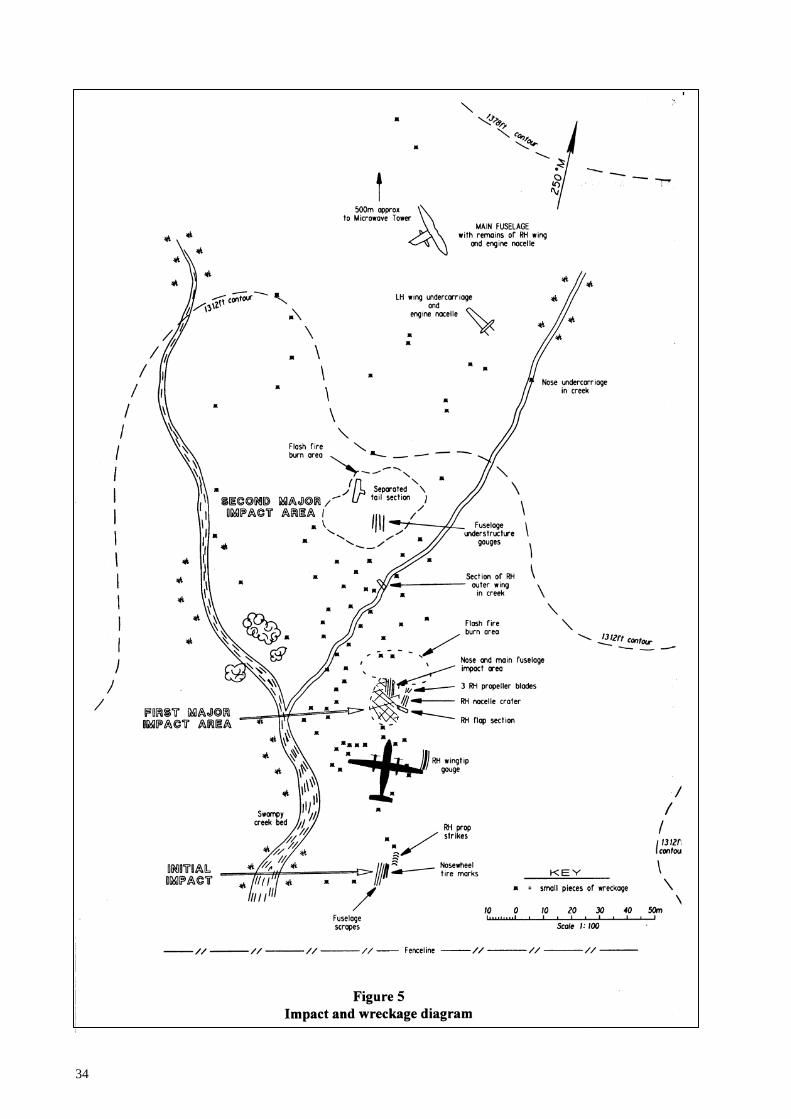
34

35
1.12.4 The initial ground impact occurred as the nosewheel of ZK-NEY contacted a gently rising grassy knoll which had an overall up-slope of about 5°. The aircraft was approximately level laterally at the time.
1.12.5 Scrape marks extending over a distance of nine metres, paint flecks and small items of debris
from the fuselage skin showed that the underside of the aircraft struck the knoll subsequently. 1.12.6 The limited extent, and shallow scoring of the short cropped grass, indicated that the fuselage
ground contact in this area was brief and involved little structural distortion. The alignment of the score marks showed the aircraft to have been tracking on 253° M.
1.12.7 The surveyed elevation of the initial impact point was 1272 feet amsl. 1.12.8 The ground dropped away steeply to the left of the knoll, allowing the aircraft’s left wing and
engine assembly, including the fully extended and locked down left main undercarriage, to clear the terrain.
1.12.9 The ground to the right of the knoll sloped upwards. The smooth grass surface retained a series
of well-defined slash marks, which had been produced by the right propeller, about 100 mm in depth and 1050 mm apart. In normal circumstances the aircraft’s propellers would have been rotating at 900 rpm at this stage of the approach. At 900 rpm the distance between the propeller slashes was consistent with a ground speed, at initial ground contact, of 122 knots.
1.12.10 As a consequence of the ground strike, the majority of items recovered at the commencement of
the wreckage trail were widely scattered fragments from the tips and outer portions of the right propeller blades.
1.12.11 The grass in the location where the right main undercarriage, had it been extended, would have
made ground contact, was undisturbed. The absence of any tyre marks, which in the case of the nose undercarriage ground contact were clear and unmistakable, established that the right main undercarriage had either been held up by the uplock or had not descended far enough for the wheels to strike the ground. The normal ground clearance of the propeller tips with the main wheels on the ground is 37 inches (940 mm).
1.12.12 While the impact forces at the point of first ground contact were light, the brief rolling contact of
the nosewheels on the upsloping knoll probably resulted in a positive fuselage pitch change and assisted in deflecting the aircraft’s flight path upwards. Consequently the aircraft continued for some 42 m on an ascending path of about 5° before the right wing tip gouged the soft earth of the nearby hillside for seven metres.
1.12.13 Approximately 28 m further on and 70 m beyond the grass knoll, the aircraft struck a terraced
grass spur which had an upslope, in the impact area, of about 30°. The orientation of the spur was such that the major impact was absorbed by the aircraft’s fuselage, right engine and right wing assembly. Three of the four already damaged right propeller blades detached from their hub and a four-metre-long section of the right outboard wing flap, together with smaller portions of other components from the lower fuselage and right side of the aircraft, were strewn over this impact area.
1.12.14 The subsequent scatter of assorted items of wreckage as the aircraft continued up the hillside,
beyond this major impact area, showed that significant structural disruption and weakening had taken place, including the loss of integrity of the rear fuselage/tail assembly aft of the pressure bulkhead.

36
1.12.15 The aircraft had yawed to the right as a result of the impact forces, and after lofting some 60 m across a gully it struck the hillside again. During this second major impact, the tail section separated, and the entire left wing assembly, including the engine and extended left main undercarriage, broke away from the fuselage. The tail section fell onto the hillside approximately 140 m upslope from the initial impact point.
1.12.16 The left wing and engine assembly slid inverted along the hillside in the general direction of the
aircraft’s travel before coming to rest 200 m from the first point of ground contact. 1.12.17 The damaged fuselage section comprising the flight deck and cabin, with the remains of the right
wing and right engine installation loosely attached, continued uphill until brought to rest against a bank on the hillside, having traversed a total distance of about 235 m from initial impact. The fuselage was slewed through some 150° and lay across the slope on a heading of 040°M partially rolled onto its left side, at an elevation of 1345 feet amsl.
1.12.18 Information from the aircraft’s flight deck included the following:
“The power levers were both fully forward. The condition levers were similarly forward, in the maximum propeller rpm position. However, the positions of these levers “as found” did not necessarily reflect their pre-impact configuration due to the extensive disruption which had occurred during the accident sequence. The flap selector lever was in the 0o detent. The pointer of the Flap Position Indicator, mounted in the instrument panel, indicated that the flaps were up.
The Captain’s and First Officer’s altimeters provided a drum and pointer display of barometrically corrected altitude using information from the air data computer. The sub-scale of the Captain’s altimeter, as found, was part way between 1011 hPa and 1010 hPa. The sub-scale of the First Officer’s altimeter was set to 1010 hPa. Both altimeters, by drum and pointer, indicated 1260 feet. A failure flag was showing in front of each altitude counter. The standby ‘barometric’ altimeter sub-scale setting was 1011 hPa. The instrument’s drum and pointer display read 1470 feet. The Captain’s and First Officer’s Static Source Selectors, which were located independently, were both selected to ‘NORMAL’.
1.12.19 The undercarriage selector lever was selected fully ‘DOWN’. The adjacent Selector Lever Lock
Release knob was in its uppermost position. 1.12.20 Alternate undercarriage extension controls were located in the flight deck roof above the First
Officer, and in the floor area to the left of the First Officer’s seat. The overhead panels had sustained considerable disruption and the plastic trim surrounding the Landing Gear Alternate Release Door and the associated L/G Down Select Inhibit Switch had collapsed. The Inhibit Switch incorporated a hinged cover to guard, under normal circumstances, against inadvertent switch activation. The Inhibit Switch was found in the ‘NORMAL’ position with the guard closed over it; however, subsequent closure of the guard during the impact sequence would have moved the switch to the ‘NORMAL’ position and resulted in the ‘as found’ condition.
1.12.21 The Landing Gear Alternate Release Door was open and the Main Gear Uplock Release Handle
was hanging down, exposing some 750 mm of the release operating cable, to which the handle was securely attached. Significant structural distortion affecting pulley locations and cable runs, and tensile overload failures of the cable installation caused by the aircraft break-up, rendered it impracticable to determine conclusively the pre-impact integrity of the cable release system. There was no evidence found to suggest that it was not capable of satisfactory operation.

37
1.12.22 The damage and disruption precluded determination as to whether the Main Gear Release Handle had been pulled in flight to the second ‘pulse’ (i.e.: sufficiently to manually disengage the uplock latch from the leg-mounted roller and allow the ‘hung’ right undercarriage leg to commence descending). However, the aft doors of the intact left engine nacelle were fully open, and damage to recovered portions of the aft doors from the right nacelle indicated that they were also open at impact. This confirmed that the alternate extension sequence had been activated to at least the first stage by the pulling of the uplock release handle. The uplock roller was not in the uplock latch on the right main undercarriage.
1.12.23 The Landing Gear Alternate Extension Door, located on the flight deck floor, was fully open.
The socket of the hand pump assembly, accessible with the panel door open, was unobstructed. The pump handle was lying on the collapsed coaming adjacent to the flight deck window to the left of the Captain’s seat. The pump handle was normally stowed against the bulkhead behind the First Officer, its lower end located in a metal ‘cup’, and the upper end restrained by a short bungee cord. No damage had occurred to the cup or bungee retaining assembly, providing supportive evidence that the pump handle had been removed from its stowage prior to ground impact.
1.13 Medical and pathological information Impact and injury characteristics 1.13.1 The aircraft flight deck and cabin received at least two major impacts with a large vertical
deceleration and a deceleration along the longitudinal axis. The result of the impact forces threw the occupants forwards and downwards, injuring the crew and most of the passengers. Extensive damage was inflicted on a number of the passenger seat mountings but in the forward part of the cabin this did not result in the seats breaking free.
1.13.2 Both wings broke away from the fuselage, imposing major torsional forces on the fuselage in the
areas adjoining seat rows 4 to 8 and significant lateral forces on the seats. 1.13.3 Prior to coming to rest the lower part of the fuselage structure failed and split longitudinally,
resulting in a height difference of up to a metre between the right and left halves of the cabin floor.
1.13.4 The aircraft rocked significantly during the impact sequence causing many passengers to sustain
substantial contacts between the fuselage, or other passengers, and their heads, shoulders, chests and arms.
1.13.5 During the initial vertical impacts, many of the mountings for the cabin ceiling and the baggage
lockers failed, resulting in a partial collapse of the ceiling and lockers. Most of the disruption to the baggage lockers occurred in the wing root area.
1.13.6 Debris and some aircraft structure intruded into the cabin during the deformation of the fuselage
The greater localised forces in the wing root area transmitted through the seats resulted in a greater severity of injury to passengers seated in rows 5 to 9.
1.13.7 The relationship of injuries to the deformation of the aircraft’s seats and fuselage correlated
accurately with the calculated forces of the impact sequence detailed above. (See Table 1.)

38
Seat A B F G Row 1
Unoccupied
Unoccupied
Unoccupied
Fatal injuries (unrestrained)
SB: Missing. SS: Intact, base missing. Extensive bulkhead damage.
SB: Deformed SB: OK SS: OK
SB: Deformed. SS: Deformed due to fuselage damage.
2 Fractured ankle.
Crush injuries to fingers
Unoccupied
Fracture lumbar spine and right
shoulder
SB: Minor damage. SS: Minor damage.
SB: Deformed laterally. SS: Broken off.
SB: Deformed. SS: Intact. Result of loose articles.
SB: Minor damage. SS: Intact
3 Minor facial injuries and neck
strain
Unoccupied
Post accident burns
Chest injuries
SB: Deformed. SS: Intact.
SB: Deformed. SS: Rear seat leg damaged by direct rear impact.
Seat ejected from aircraft Seat ejected from aircraft.
4 Mild concussion
Unoccupied
Unoccupied
Broken collar bones, right
shoulder and ribs
SB: Intact. SS: Damaged at rear from impact.
SB: Intact. SS: Damaged at rear from impact.
SB: Missing. SS: Intact.
SB: Missing. SS: Intact
5 Unoccupied
Unoccupied
Unoccupied
Spinal injury
SB: Intact. SS: Intact.
SB: Deformed SB: Missing. SS: Minimal buckling.
SB: Deformed. SS: Buckled.
6 Chest injuries
Unoccupied
Unoccupied
Fatal back and head injuries
SB: Damaged. SS: Broken free and severely damaged.
SB: Damaged. SS: Broken free and severely damaged.
SS: Broken at base and ejected from aircraft.
SS: Broken at base and ejected from aircraft.
7 Broken ankle and index finger
Fatal injuries, head neck and
chest
Unoccupied
Unoccupied
SB: Intact. SS: Broken high on legs.
SB: Intact. SS: Broken high on legs.
SB: Intact. SS: Intact. Uninhabitable space due to floor intrusion.
SB Deformed. SS: Lateral damage due to deformation of fuselage.
8 Neck and head injuries
Unoccupied
Unoccupied
Unoccupied
SB: Deformed. SS: Broken at floor. Mounting indication major forward and lateral loadings.
SB: Deformed. SS: Broken at floor. Mounting indication major forward and lateral loadings.
SB: Severely damaged. SS: Intact.
SB: Severely damaged. SS: Intact.
9 Unoccupied
Unoccupied
Right fractured ribs
Bruising
Parallelogram deformation indicating severe lateral impact.
Parallelogram deformation indicating severe lateral impact.
SB: Intact. SS: Intact.
SB: Deformed. SS: Intact.
10 Unoccupied
Unoccupied
Fractured lumber spine.
Fractured femora
SB: Intact. SS: Intact
SB: Affected by rear bulkhead damage. SS: Some arm rest damage and minor seat deformation.
SB: Affected by rear bulkhead damage. SS: Minor deformation.
SS: Severe deformation from fuselage damage. SS: Similar.
Table 1 Key: SB = seat back, SS = seat support Relationship of injuries to cabin occupants with seat damage and seat position

39
1.13.8 Most of the occupants’ injuries, including those of the crew, were to the head, neck and chest. Passengers’ injuries to the lower limbs from impact with the seat in front of them were minor, suggesting there was relatively little flailing.
1.13.9 Many of the head and facial injuries were sustained early in the impact sequence when restrained
seat occupants were thrown forward onto the back of the seat immediately in front of them. These injuries often caused minor concussion which in some passengers caused a brief period of unconsciousness or confusion; this together with exit obstruction or entrapment, delayed emergency exit from the aircraft onto the hillside after the aircraft came to rest.
1.13.10 Some injuries were caused by contact with loose and penetrating objects entering the cabin area
normally occupied by passengers and crew. 1.13.11 Both of the pilots remained conscious but were incapacitated by serious head injuries. 1.13.12 The flight attendant was leaning over the back of seat 1G facing rearwards at the time of the
impact and was thrown to the floor sustaining fatal injuries to her head. The Flight Attendant’s rearward facing seat was adjacent to the front left exit door facing seats 1A and 1B.
1.13.13 The other two immediate fatalities involved passengers seated in the rear mid-section of the
aircraft. One was thrown, in his seat, onto another seat two rows forward, sustaining major chest injuries. The other died from chest injuries sustained while still restrained, due to additional localised impact loads from seat dislodgement.
1.13.14 The latter two fatalities were due to impact forces, well in excess of the survival design
parameters, sustained either due to direct injury or through seat mounting failure. 1.13.15 One further fatality occurred involving a passenger who, while waiting outside the aircraft,
became enveloped in a small, short-lived fire which erupted at the rear of the right engine nacelle. He survived initially but died 12 days later in hospital from extensive burns.
1.14 Fire 1.14.1 Post-impact fire had occurred in a number of areas during the accident sequence. 1.14.2 Following the aircraft’s initial contact with a grassed knoll the right wingtip gouged into the
adjacent hillside and the fuselage and right engine then struck the slope. 1.14.3 The progressive rapid disruption of the right wing outboard structure released a large volume of
fuel from the right tank, and scorching of the grass over a widespread portion of the impact zone indicated that a flash fire had ensued.
1.14.4 Of the sources of ignition, the most likely was an exposed flame from the right engine exhaust
ducting which sustained major damage and disruption at impact. Burn marks and sooting on items of wreckage scattered in this area and beyond suggested that in addition to the overall effect of a transitory fireball due to the ignition of misted fuel, small isolated pockets of puddled fuel had ignited and had burned for a longer period.
1.14.5 The aircraft’s vertical and horizontal tail surfaces were sooted in a manner consistent with the
occurrence of a similar brief flash fire in the area of the second major impact further up the hillside where the already weakened empennage and left wing and engine assembly separated from the fuselage structure. It was also likely that some sooting and fire damage resulted from immediate or subsequent burning of fuel droplets deposited on the tail surfaces when the right wing fuel tank was first ruptured.

40
1.14.6 The impact sequence was such that the left wing broke away from the fuselage in the region of the centre section. The left fuel tank bay located outboard of the engine nacelle sustained minimal damage resulting in only a minor leak. A considerable quantity of fuel remained in the left tank until the aircraft wreckage was removed from the accident site three days after the accident. Fuel from the left tank did not contribute to the fire. There was no significant sooting or fire damage on the separated left wing and engine, indicating that the effect of the flash fires at the major impact locations was confined to the right side and rear of the aircraft.
1.14.7 Survivor reports indicated that after the fuselage had come to rest a small and non-threatening
fire was observed burning on the right side of the aircraft. The broken centre section and inboard portion of the right wing, although almost detached from the fuselage, still lay across it. The right engine nacelle and remaining structure of the outboard wing had collapsed onto the ground. Due to the angle at which the wreckage was lying it was likely that residual fuel was pooled in the vicinity of, and beneath, the rear of the right nacelle.
1.14.8 The exhaust duct had separated from the rear of the right engine. The fire which persisted in this
area may have been sustained due to the proximity of the damaged engine and its hot section component parts.
1.14.9 After a number of survivors had made their way from the aircraft, the existing fire flared up
suddenly in an explosive manner engulfing an extended area. Although it diminished in intensity quickly, it was this intense and unexpected conflagration that trapped and enveloped a nearby passenger.
1.14.10 Site examination and the evidence of survivors indicated that, with the exception of the fire
adjacent to the aircraft fuselage, other outbreaks of fire which occurred during the impact sequence were relatively short-lived, and self-extinguished.
1.14.11 No attempt was made by the survivors to use the on board portable fire extinguishers on the small
fire in the right wing area. 1.14.12 Rescue activities, undertaken approximately one hour after the accident, did not involve fire
suppression as the fire in the right engine nacelle area had burnt out. 1.15 Survival aspects
Rescue operations 1.15.1 At 0926 hours Palmerston Tower alerted the Police, the Airport Rescue Fire Service, the New
Zealand Fire Service and Palmerston North Hospital, that a Dash 8 aircraft had gone missing during an instrument approach to Palmerston North Aerodrome. This action followed unsuccessful attempts by the Tower and Ohakea Control to contact Ansett 703, and after confirming with Ohakea Control that the aircraft had disappeared from radar.
1.15.2 The emergency services notified by the Police included the Fire Service, ambulance, Civil
Defence, the Palmerston North Airport Disaster Team, the Airport Rescue Fire Service, the Airport Medical Officer, Palmerston North Hospital, and the rescue helicopters.
1.15.3 As the exact location of the aircraft was not known, the emergency services were instructed to
assemble together at a specific point and await further instructions. Nine ambulances, each with a crew of two, responded. The Fire Service dispatched three appliances, a command vehicle and a tanker, and the Police sent 30 personnel. The Airport Rescue Fire Service also provided a vehicle and personnel.
1.15.4 The search was centred initially on a position equating to four nautical miles final for runway 25,
which was where the Ohakea Air Traffic Controller involved thought the aircraft was most likely

41
to be. A ground search by Police and rescue vehicles was augmented by a helicopter from Palmerston North at 0939 hours, and a second helicopter from Hastings at 1000 hours.
1.15.5 A few minutes after the accident, a passenger from the aircraft used his portable cellular
telephone to make an emergency call to the Police, reporting that the aircraft had “crashed” in a paddock with no road access. The Palmerston Surface Movements Controller then made telephone contact with the passenger and was able to ascertain the condition of the survivors: that they were on a grassy hill top and in cloud with limited visibility and their position was indeterminable. He gave them advice on survival strategy while the search progressed, and also obtained a description of the only significant feature visible in their vicinity, which was a large stock pen.
1.15.6 From telephone inquiries of local farmers, the probable access road to this stock pen was
discovered and ground vehicles were directed to it. The controller also got the passenger to report to him when the sound of a helicopter was heard. This information was relayed to the helicopters by RTF, thus narrowing their search area to some extent. The effectiveness of this process was reduced by the presence of two helicopters between which the passenger could not differentiate.
1.15.7 The two helicopters were instructed to search initially on the Ashhurst side of the Manawatu
Gorge and then the Woodville side of the gorge. The helicopters searched both visually for the aircraft and electronically for its ELT.
1.15.8 One helicopter had been searching visually at low level, below the cloud base and hence below
the accident site, while the other searched electronically at altitude, in or above cloud. When they were both able to receive the weak ELT signal on their homing equipment, and were in mutual visual contact, the pilots were able to track to the ELT by hover-taxiing over the hilly terrain, in cloud and poor visibility. Despite the flying conditions the wreckage was located at approximately 1019 hours.
1.15.9 Police and paramedic personnel on the helicopters were off-loaded near the wreckage, and both
helicopters then flew to Palmerston North Hospital to collect medical staff and return them to the scene. Four further helicopters had been instructed to assist and arrived at the site to help with the evacuation of the injured, and for general transportation. The ground vehicles arrived a few minutes later.
1.15.10 Treatment and rescue of the aircraft’s occupants began without further delay. 1.15.11 At 1022 hours a road block was established at Hall Block Road and a medical trailer proceeded
up this road to the scene. A command post was established on the crest of a hill near the accident site at approximately 1039 hours. On arrival at the road block the Airport Medical Officer assisted the ambulance staff before proceeding to the site.
1.15.12 A doctor on site assisted with the triaging of the injured, and the survivors were transported by
helicopter to the ambulances stationed near the road block or were flown direct to Palmerston North Hospital. Some of the more seriously injured were transported by helicopter to Wellington Hospital. The first survivor arrived at Palmerston North Hospital by helicopter at about 1100 hours and the last survivor arrived by road ambulance at 1207 hours.
1.15.13 Further assistance was provided by the Army. The Salvation Army and members of other
volunteer organisations who arrived at the scene during the proceedings also offered their assistance. A contingency force at RNZAF Base Ohakea was put on standby at the request of

42
Figure 6a View of passenger cabin looking aft
Figure 6b View of flight deck

43
the Airport Medical Officer and was stood down when the last of the survivors had been removed from the accident scene.
1.15.14 The deceased were removed from the scene by 1500 hours. 1.15.15 A Victim Support Group was mobilised by the Police and sent to Palmerston North Aerodrome
and the Palmerston North Hospital to assist as required. 1.15.16 The Air Traffic Control Radar recording, when subsequently studied, showed information which
had the potential to assist with the search for the aircraft after the accident, had it been available quickly. Because of this, the necessary procedure to obtain a playback of the recording was investigated.
1.15.17 When a request for a playback of current radar data was made, the first step was to switch from
the active computer to a standby computer, which occupied a minimum of five minutes. The recorded data, in eight files, then had to be down loaded from the hard disc storage to a tape. The tape then had to be searched on a playback machine to find the appropriate data.
1.15.18 The normal minimum time required before a radar recording could be studied to assay the data
was about 40 minutes, but could be up to 1 hour 40 minutes, and at least 15 minutes extra would then be required to find the relevant information and notify the RCC.
1.15.19 The Airways Corporation did not have an early radar recording search arranged as part of their
standard response system, but facilities and personnel were generally available to accomplish this should it be requested.
Post accident survival factors 1.15.20 The limited involvement of the fuselage in the post-impact fire increased the post-impact
survivability. Apart from the short-lived fire which occurred in the area of the right engine, most of the spilt fuel was consumed in two flash fires early in the impact sequence. Significant delays in effecting emergency egress were experienced by some passengers because of seat dislodgements and an accumulation of debris in the cabin. (Figures 6a and 6b.)
1.15.21 The door at seat 1G was opened by the impact forces and the window exits at seats 4A and 4G
were also used as exits as was the large opening caused by the failure in the left wing root area. The large opening also enhanced the light level in the interior of the cabin, despite the overcast sky and fog conditions.
1.15.22 Exit from the aircraft was impeded by debris from loose seats, and by the collapse of the roof
section in the mid-cabin area. This situation resulted in some passengers being trapped in the aircraft for 30 to 60 minutes after the accident.
1.15.23 The shelter of the fuselage probably protected some of the more seriously injured from exposure
to the weather and consequential hypothermia. 1.15.24 As the initial concussed and dazed state of the more able survivors wore off, some became active
in caring for the more seriously injured. At least one looked for a first aid kit but the lack of a clear indication of its existence prevented it being found. Others helped extricate the remaining individuals trapped in the wreckage and located items to act as insulation from the chilling wind and rain. Aircraft insulation and scattered clothing were gathered for this purpose.

44
Survivability 1.15.25 The energy absorbed by the aircraft structure and the extended stopping distance made the impact
survivable. 1.15.26 In most cases the energy absorbing collapse of the seat supports which permitted continued
restraint of seat occupants in the front and rear cabin also promoted survival. Seating design and mountings in these areas performed in excess of the normal design parameters. Seat structure and mounting failures resulted from additional laterally transmitted forces associated with the failure of the structure in the wing root area. More injuries would have occurred due to the longitudinal split in the fuselage had seats 4F to 8F been occupied.
1.15.27 Despite failure of the internal roof trim and overhead baggage locker mountings throughout the
fuselage the lockers remained latched, reducing the potential for injuries from loose objects. Although the habitable spaces in the forward cabin were reduced to the survivable minimum, serious injuries were avoided in this area.
1.15.28 The hostile weather conditions on the exposed hillside caused considerable distress to the
surviving passengers. Once the post-accident fire had died out and the area had been made safe, it would have been appropriate to use the cabin area for shelter, had any longer delays in rescue been experienced. In this case lack of shelter did not affect the survival rate.
1.15.29 The aircraft’s two first aid kits were stowed in a locker located in the forward right cabin area.
Their location was indicated by a small green cross. Their existence was not mentioned during the passenger safety briefing nor on the safety briefing card. Neither was located by the survivors or those who came to assist in the rescue of the occupants subsequently.
1.15.30 Many members of the public are trained in, and would have been able to administer, first aid
given the appropriate equipment. Aircraft first aid kits were available but their locations were not marked clearly. The need for discretion in marking the location of these kits has been minimised since the removal of narcotics from them post 1987 reduced the risk of their theft.
1.16 Tests and research
The undercarriage 1.16.1 Following the accident the right main undercarriage uplock assembly and the associated roller
from the right undercarriage leg were transported to Canada by the Investigator from the Transportation Safety Board of Canada who participated in the site investigation as the Canadian Accredited Representative.
1.16.2 The latch sub-assembly, part number 10812-11, had serial number DCL067. The uplock
assembly, part number 10800-109, had serial number DCL 099/85/88 Mod SB 32-50. 1.16.3 The manufacturer’s records indicated that the latch, part number 10802-7, manufactured by
Messier-Dowty Incorporated, Canada, was fitted new to the uplock assembly in 1988. Satisfactory acceptance test results were achieved on the unit at this time, and in 1989 when it was tested following incorporation of Modification SB 32-50.
1.16.4 To accommodate the removal of in-service wear, the Messier-Dowty Component Maintenance
Manual (CMM) permitted the re-profiling of the latch a maximum of five times, each ‘rework’ repair being identified by a letter/number code.

45
1.16.5 The latch had last been reworked by Messier-Dowty during May 1993 in accordance with the specifications in the CMM for a third repair, and was designated CRS 85-84-3. Messier-Dowty had issued a Maintenance Release tag following this repair indicating the latch sub-assembly was acceptable for service and reverted to zero hours total time.
1.16.6 Ansett New Zealand Limited Engineering had received the latch sub-assembly from Messier-
Dowty as an exchange unit. It was installed on ZK-NEY on 4 September 1993 and had sustained a total of 5507 cycles prior to the accident.
1.16.7 No work had been carried out on the latch during this period of service but it had been subject to
regular inspection as required by the aircraft’s maintenance schedule. It had last been inspected on 2 May 1995 and had been assessed serviceable. The roller assembly had also been inspected and lubricated, and the uplock assembly as a whole inspected and assessed as serviceable at that time. Normally the roller assembly was lubricated every 400 hours. On the night prior to the accident it had accumulated 277 hours since the last servicing.
1.16.8 Inspection of the uplock latch on 2 May 1995 had been carried out in compliance with de
Havilland Dash 8 - 100 Systems Maintenance Programme Task # 32 3006 which specified a visual inspection of the Main Landing Gear uplock actuator. In addition, on this date, Task # 32 1007 had been completed. This task called for inspection of the Main Landing Gear Lock Mechanism for condition and wear, and involved inspection of the uplock latch assembly in accordance with Ansett New Zealand Limited Engineering Technical Instruction TI 008 - 32 -014A. The TI referred to the potential for wear in the latch to result in an undercarriage hang-up, and required “inspection of the latch assembly for evidence of wear particularly in the latch detent area where the uplock roller sits”. If excessive wear was found the latch assembly was to be repaired or replaced. No dimensional limits in respect of the wear pattern resulting from roller contact on the latch surface were specified in the TI. Engineering staff, however, were accustomed to inspecting the latch detent area regularly and assessing the extent of wear by sight and touch.
1.16.9 The manufacturer routinely updated the maintenance programme, and had issued a Temporary
Revision SUP-383 in November 1994. This Revision added the following note to the procedure for Task # 32 3006. Visual inspection of MLG Uplock Actuator.
NOTE: For Pre Mod 8/1764 and Pre Mod 8/1828 aircraft, look for wear on uplock latch where roller engages (refer to PSM 1 - 8 - 6 Component Maintenance Manual, Chapter 32, Dowty 32 - 30 -04 for wear limits).
1.16.10 There was no compliance date associated with the Temporary Revision, nor indication of
urgency, or safety implication, in regard to its incorporation in the maintenance programme. The manufacturer did not draw operators’ attention to the issue of the Temporary Revision and its contents, by means of an AOM, safety alert, or other method normally employed if important safety information was distributed.
1.16.11 The Temporary Revision was received in Ansett New Zealand’s Technical Library in December
1994. However, the engineering planning section did not action the Revision until 2 May 1995 due to the build-up of a backlog of amendments as a result of staff changes. The modification kits had been on order for some time, and two units had already been installed (see paragraph 1.6.52) which led the maintenance planning team to state on 2 May 1995 that no action was required in relation to the Revision. The Note providing a reference for wear limits was thus not included in the written task procedure for inspections, after that date, on the pre-modification latches.

46
1.16.12 Messier-Dowty examined the uplock assembly, latch, and roller, and subjected relevant components to tests. The examination and tests were carried out under the supervision of the Transportation Safety Board of Canada’s Accredited Representative.
1.16.13 Results of the examination and tests were summarised as follows:
The uplock assembly in its fire and impact damaged condition was subjected to a partial Acceptance Test procedure:
a) The testing involved verification of the hydraulic pressure
required to unlock the mechanism, and recording of the load required to operate the manual release.
The hydraulic pressure to release the uplock was found to be 2000
psi/1850 psi (dependent on aft/fwd adjustments). The acceptance range was 550-1050 psi (aft adjustment) and 400-
900 psi (fwd adjustment).
The Manual alternate extension system operated satisfactorily at 64 and 40 pound of pull (aft/fwd adjustments). Normal unlocking force for Emergency Extension ranged from 5 to 22 pound (for both aft and fwd adjustments).
b) The uplock latch Part No. 10802-7 was subjected to a profile
check on a co-ordinate measuring machine. A wear pattern on the latch surface where the roller makes contact was found to have a width of 0.195 to 0.220 inches (4.95 to 5.59 mm) and a depth of 0.006 inches (0.152 mm).
CMM 32-30-04 Temp Rev. 32-1 dated 1 November 1994 provided inspection criteria for surface wear on the latch. The wear-band width was stated as indicative of the depth of wear. Maximum allowable wear-band width was shown as 0.125 inches (3.18 mm). The fire damaged condition of the uplock latch prevented the metallurgical laboratory from determining the inter relationship of indentations and wear. The laboratory reported ‘Damage marks could be caused by both wear and crash damage’. c) The rigging of the uplock target, relative to the proximity switch
bracket stop face, and relative to the proximity switch, was found to be incorrect.
d) Metallurgical tests to determine the hardness of the uplock latch
and the uplock lever were inconclusive. Hardness readings varied to the extent that they were considered invalid due to the effects of the fire on the mechanical properties of the parts.
Messier-Dowty presented the following conclusions:
(i) Heat damage to the seals, lined bushings, ‘O’ rings and internal springs of the uplock assembly meant that the actual pressures and loads measured in the post-accident tests may not have accurately represented the ‘in-flight’ loads and pressures. However Messier-Dowty’s experience with previous uplocks indicated that the wear on the latch would have prevented the uplock assembly from passing the relevant acceptance test procedure.
(ii) The extent of wear on the latch exceeded the limits published in Messier-
Dowty CMM 32-30-04 Temp Rev 32-1. Based on the manufacturer’s

47
experience, the wear condition, as determined, was sufficient to have prevented release of the undercarriage leg using the normal undercarriage extension procedure. It would not however have prevented manual/alternate release.
(iii) The ‘mis-rigged’ condition of the target and proximity switch would not
have affected the function of the uplock assembly. However, it may have provided the crew with an erroneous (or intermittent) flight deck indication. It also provided an explanation for the condition of the uplock lever which was found to be bent.
(iv) Metallurgical testing of the uplock latch and uplock lever was
inconclusive. (v) Modifications and repairs to the uplock assembly had been performed
correctly. It had passed earlier acceptance tests satisfactorily.
The GPWS computer 1.16.14 The Sundstrand GPWS computer was recovered undamaged from the aircraft and was taken to
the manufacturer for testing and analysis. 1.16.15 A bench test showed that the computer was operative and a complete production Acceptance Test
Procedure (ATP) showed that the computer was serviceable and completely within all production specifications. The tray for the computer and the connector were intact and serviceable. The rear pins showed that the system had been programmed for normal air transport operation.
1.16.16 The DFDR did not record the radio altitude, so for simulation purposes this parameter was
derived from a terrain profile along the aircraft’s apparent track. By subtracting the terrain profile from the DFDR altitude, a pseudo radio altitude was constructed. While errors will exist, experience has shown that the radio altitude for a normal functioning system would have matched within 10 % of the derived values.
1.16.17 A flight parameter table applicable for GPWS simulation test purposes for the last two minutes
of flight (undercarriage up, flap up) was constructed from the DFDR parameters. Time was constructed in conjunction with the ground speed readout from the radar plot, and the pseudo radio altitude used. These were formatted into engineering units onto a 3.5 inch disc, and a number of separate simulations were performed:
A Personal Computer flight animation programme was used to compile the flight parameter data and the GPWS alert/warning times calculated and displayed. The first warning, “Terrain! Terrain!”, was shown visually 15 seconds before impact. A Virtual Addressing Extended (VAX) simulation was run independently from the above flight parameter table, and it showed the first “Terrain” warning starting at 17.5 seconds before impact. Another Mark II GPWS modified in accordance with the latest Service Bulletin instructions showed the same result. A laboratory test using the Batch Orientated System Simulation (BOSS) equipment was also carried out. Aircraft signals formatted to represent actual signals that the GPWS computer would have seen, during the period leading up to the accident, were compiled and the actual subject computer and a reference Mark II computer, to the same modification status, were run. Identical warnings were received from both computers and the first warning, measured by stopwatch, occurred 18 seconds before impact. A Mark II computer modified to the latest status was also operated with the same result.

48
Tests were also run on all three simulations with the “Flap Override” switch activated to give a flap down indication to the GPWS computer. The three results were the same with a “Too Low, Terrain” warning occurring at 500 feet radio altitude and 13 to 14 seconds before impact.
1.16.18 Simulation tests were performed using a track slightly north of the determined track in an attempt to match the actual GPWS warning as recorded on the CVR. The first warning by simulation occurred some 18 seconds from impact, and neither the “flap override” nor an “undercarriage down” discrete would duplicate the warning.
1.16.19 Using the BOSS simulation, the radio altimeter validity was interrupted at some 20 seconds from
impact to simulate sudden loss of radio altimeter tracking where the terrain was rapidly changing. This did give, under the right interrupt conditions, a “Terrain, Whoop Whoop Pull-Up” warning, just before impact.
1.16.20 A concern that the undercarriage alternate extension procedures may have affected the normal
undercarriage “Down And Locked” signal to the GPWS received the following response from the aircraft’s manufacturer:
The GPWS system receives a landing gear ‘down and locked’ signal from the Proximity Switch Electronic Unit (PSEU), which in turn receives real time output from proximity switches on the landing gear. All 3 landing gear have to be in a down and locked position before a down and locked signal is sent from the PSEU to the GPWS. The Landing Gear inhibit switch removes 28 volts from the down solenoid of the landing gear selector valve, and does not have any effect on the PSEU output signal to the GPWS. Neither the main ‘Landing Gear Alternate Release’ door nor the ‘Main Landing Gear Release’ handle (both located in the flight deck roof) affect the PSEU output signal to the GPWS.
The Captain’s altimeter 1.16.21 On 16 February 1996 the Captain wrote to the Commission. In that letter he mentioned his
recollection of the altimeter jumping “I think from 2800 to 1800 feet”. The Captain’s altimeter was not damaged in the accident so it was tested functionally from 30 000 feet to sea level. The test showed a linear indication throughout the altitude range in accordance with normal serviceability requirements.
1.16.22 The test was not in itself conclusive. The disruption to the aircraft during the impact sequence
rendered it impracticable to confirm with certainty that no malfunction had occurred within the system supplying data to the Captain’s altimeter.
1.16.23 The aircraft was equipped, however, with an independent “standby” altimeter for reference and
cross-check, in addition to the Captain’s and First Officer’s altimeters. 1.16.24 The altitude alert light was also examined. It showed no indication which would assist in
determining whether it was on or off at the time of the aircraft’s major impact with the terrain. The filament was undamaged.

49
1.17 Organisational and management information
Ansett New Zealand Limited Background 1.17.1 Ansett New Zealand Limited adopted the operating practices of Ansett Australia at the inception
of the airline. Operating manuals and general operating procedures were intended to be aligned as closely as practicable apart from variations for the New Zealand operating environment and specific aircraft types. The common approach was not imposed but shared. Senior Ansett New Zealand operational staff participated in the Ansett Australia Flight Operation Group meetings.
1.17.2 The original Flight Training and Safety Manager was responsible for introducing the company
CRM programme into the recurrent training syllabus. He complemented this with his interest and experience in wider safety issues.
1.17.3 Neither the original Flight Training and Safety Manager nor any of his successors had undergone
formal accident prevention or flight safety training. 1.17.4 The fundamental change in flight safety management procedure occurred in June 1993 as a result
of a review of the former flight safety programme, as conducted by the erstwhile Safety Manager. Following the Safety Manager’s return to full-time line flying, the operator decided that a flight safety effort reliant on one individual did not provide a clear view of the safety of the Ansett New Zealand operation. The operator resolved to ensure the flight safety information that was captured was not reduced by any “reticence of line crews to share issues with management”.
1.17.5 The aircraft crew members were encouraged to submit reports of anything which they considered
might lead to a degradation in the safety of their operation. The intention was that the operator’s flight safety infrastructure should respond to these reports positively to prevent such incidents leading to accidents.
1.17.6 Concurrently they decided to “enhance (their) ability to react to line generated reports by data
basing, trending and circulating (these) to managers who were able to make the necessary changes”.
1.17.7 The operator stated in relation to these changes:
This effort was supported by a co-ordinator to provide another avenue of comment for crews, and the necessary bypass to the Chief Executive.
The overriding thrust was to involve all managers in Flight Safety.
The responsibilities and authority of the Flight Safety Co-ordinator exceed those of the earlier regime...and results in a more timely resolution of potential issues. Previous reliance on (a) large Flight Safety Panel dealing with events was not wholly effective. The close integration of CRM training with (the) Safety Role has been deliberately continued.
The position of Flight Safety Co-ordinator was not a replacement for the earlier position identified as the Flight Training and Safety Manager. It was a new position supporting a re-designed programme based on a General Flight Reporting System involving two management positions with the overriding policy that all managers were required to assume responsibility for the issues presented to them.
This had the effect of providing a dedicated Flight Safety thrust independent of the training bias of the earlier position.

50
1.17.8 Those charged with the implementation of flight safety by the company did not receive the training, exposure to overseas safety conferences or international collaboration on safety to the extent evident in many larger airlines.
1.17.9 The Ansett New Zealand Flight Operations Policy Manual, Section 6 - Flight Safety Programme,
dated June 1993, was produced as a current document. It stated inter alia:
The Flight Safety Programme within Ansett New Zealand is established by the provision of all those systems necessary to support Airline Operations.
The programme utilises the principles of observation, reporting, analysis and action as a part of normal day to day operations.
Each and every operative within the division is responsible for applying common-sense flight safety principles to each and every activity.
External flight safety experience is contemplated by Airline membership of key Flight Safety Organisations.
Flight Safety trends, developments or deficiencies are monitored by the Regional Flight Managers who will ensure that expeditious and proactive interface with appropriate Managers occur.
The Flight Safety Co-ordinator may where he thinks fit, report directly to the Chief Executive Officer.
2 RESPONSIBILITY
A. Chief Executive Officer
The Chief Executive Officer is responsible for the provision of appropriate systems supporting a proactive flight safety programme. B. Manager Flight Operations
The Manager Flight Operations (MFO) is responsible to the CEO for the managing, planning and those systems in support of Safe Airline Operations.
C. Regional Flight Managers
The Regional Flight Managers are responsible to the MFO for the establishment and control of systems necessary to achieve observation, reporting and analysis of Flight Safety issues and shall ensure that significant observations and deficiencies are communicated to the appropriate Manager for action and then recorded as closed or open. D. Flight Safety Panel
A Flight Safety Panel shall be constituted by the Flight Safety Co-ordinator as required to analyse those flight safety matters not closed by management action and make such recommendations considered necessary.
E. Flight Safety Co-ordinator
The Flight Safety Co-ordinator will co-ordinate the activities of the Flight Safety Panel, co-opting such expertise as is from time to time required to resolve Flight Safety issues and where he thinks fit will report the findings of the Flight Safety Panel to the Chief Executive Officer.

51
The Flight Safety Co-ordinator shall have access to all records relating to Flight Safety and may investigate any matter he/she considers necessary with a view to monitoring the effectiveness of the Flight Safety Programme.
Monitoring the Flight Safety Programme may include:
• Review of General Flight Report trends • Consideration of Line Pilot input • Review of Internal Audit Reports
The Flight Safety Co-ordinator will review externally sourced flight safety references and make any information considered relevant available for general interest of aircrew.
1.17.10 The Flight Safety Co-ordinator had accumulated some 15 000 flying hours including 8000 hours instructing time. He had been a Captain on the operator’s DHC-7, Boeing 737, DHC-8 and BAe 146 aircraft and was a training Captain at the time of the accident. He had both A and D Category Instructor Ratings and had completed courses in Instruction Technique. He saw his role as monitoring rather than managing Flight Safety. He had not undergone any course specifically relating to Flight Safety or Accident Prevention.
1.17.11 He considered he had the resources necessary to conduct an effective CRM programme as a
facilitator of the Ansett Australia CRM programme and apart from some adverse comment on the technical quality of the copied videos and slides considered the feedback from crews was favourable.
1.17.12 He shared an office with the Regional Flight Manager Christchurch but did not receive any
General Flight Reports (GFRs) or Air Incident Reports unless the Regional Flight Managers considered them worthy of his attention. He was able to, and did from time to time, review the data base of the GFRs, to monitor trends and oversee the system if the Regional Flight Managers were absent.
1.17.13 Ansett New Zealand Limited Engineering copied their Defect Investigation Reports to the
Regional Managers. 1.17.14 The Flight Safety Co-ordinator was not privy to the company management’s decision not to
modify the Dash 8 aircraft undercarriage uplocks or to any policy decisions made which could have a bearing on flight safety.
1.17.15 Ansett New Zealand’s membership of “key flight safety organisations” was limited to
membership of the New Zealand Airline Flight Safety Committee. Ansett Australia was a member of the Flight Safety Foundation.
1.17.16 Ansett New Zealand received some incidental feedback from Ansett Australia’s membership of
this international flight safety organisation in that each of their pilots received Ansett Australia’s quarterly flight safety magazine “On Course”, and the Flight Safety Co-ordinator attended regular meetings with Ansett Australia’s flight safety representatives. Although “On Course” listed incidents experienced by Ansett Australia it did not include reference to any experienced by Ansett New Zealand.
1.17.17 Ansett New Zealand described their flight safety programme as a “pro-actively reactive”
organisation.

52
1.17.18 The Organisation Tree in the Ansett New Zealand Flight Operations Policy Manual, Section 2 Organisation, page 2, depicted the following diagram showing the FLIGHT SAFETY ORGANISATION.
FLIGHT SAFETY ORGANISATION May 1995 (Ref Ansett New Zealand Flight Operations Policy Manual Section 2, Page 2, May 1995)
1.17.19 The Engineering Management - Organisational Structure dated April 1995 showed no avenue for
engineers to volunteer safety suggestions to the Flight Safety Panel. 1.17.20 Whereas the former flight safety panel met on a bi-monthly basis and involved representatives
from most departments, the new concept involved only two permanent members (the Flight Safety Co-ordinator and one Regional Manager) and infrequent meetings, e.g. only once in the 12 months preceding the accident.
1.17.21 The panel could co-opt members from any department which it required to react to an identified
problem but based its business on finding solutions to GFRs which raised matters not able to be dealt with by the Regional and Fleet Managers or to any individual item or trend which the Flight Safety Co-ordinator considered worthy of the panel’s attention.
1.17.22 In lieu of the regular bi-monthly meetings of the Flight Safety Panel the system established was to
respond to GFRs through a “conduit of information”. The responsibility for this was that of the Regional Flight Managers who would then involve all relevant managers, including engineering and external divisions, to bring together the necessary information and personnel to address and solve the safety issue as soon as practicable “rather than to wait for up to 60 days for the next meeting of the Flight Safety Panel”. Ansett New Zealand saw this system as having significant advantages over their former flight safety procedures.
1.17.23 The Flight Safety Co-ordinator was not aware of the details of an ICAO driven initiative to
reduce the number of CFIT accidents and the associated publicity and the Checklist associated with this programme. This material was available to Ansett Australia and had been publicised indirectly in an article in their Flight Safety magazine “On Course”. The article relating to CFIT was in the latest issue distributed prior to the accident.
1.17.24 Discussions of earlier CFIT accidents were, however, prominent in the CRM syllabus for the
recurrent training programme.

53
CFIT Checklist 1.17.25 When the pilots of ZK-NEY were interviewed each said that in such an event their procedure for
responding to a “hard” GPWS warning involved the use of “go-around” power. However, the most effective response to a “hard” warning from the GPWS requires the use of maximum power immediately rather than “go-around” power.
1.17.26 One item on the CFIT checklist was “You annually practice recoveries from terrain with GPWS
in the simulator.” There was no simulator for the Dash 8 nearer than the United States (in Seattle), and there was no published procedure in the operator’s Dash 8 flight manual or other Ansett New Zealand Dash 8 document to advise pilots on the most appropriate action expected by them in the event of a GPWS warning. Ansett New Zealand advised that they covered the “appropriate pilot reaction to a GPWS warning” in the course of pilot training and expected it to be “well known by aircrew”. The First Officer stated he had received no training in this regard.
1.17.27 The CAA said they were aware of the CFIT initiative and were one of the sponsors of the video
which accompanied the Flight Safety Foundation programme. 1.17.28 Following the accident Ansett New Zealand published a procedure for the required response to a
GPWS warning in their Dash 8 Operating Manual as follows:
A General (1) Except in VMC by day, an aural warning from the GPWS will be acted upon as a command. B Procedure - GPWS Warnings (2) Upon activation of aural ‘TERRAIN TERRAIN’, ‘TOO LOW TERRAIN’ and or ‘WHOOP WHOOP PULL UP’ warning (with or without the associated PULL UP switchlight), proceed as follows:
(a) POWER LEVERS......Advance to go-around power (b) AUTO PILOT............Disengage (c) ROTATE TO GO-AROUND ATTITUDE Immediately rotate to go-around attitude while applying go-around power and establish a positive rate of climb. (d) CONFIRM/SELECT CONDITION LEVERS TO MAXIMUM RE-CHECK POWER Climb at the normal manoeuvring speed for the flap position. Trade excess airspeed for altitude by initially rotating to a higher nose-up pitch attitude until reaching the desired climb speed. (e) FLAPS.......................Call for the go-around flap position if the flaps are extended beyond that position. Otherwise, do not reposition flaps. (f) LANDING GEAR......Once positive rate of climb is established select....UP (g) CLIMB......................at the manoeuvring speed for existing flap position until terrain clearance is assured.

54
1.17.29 The manufacturer’s current Dash 8 Flight Manual procedure as amended in November 1993 stated:
Whenever the ‘TOO LOW - TERRAIN’ OR ‘WHOOP WHOOP PULL UP’ announcements are heard, immediately establish the power setting and attitude which will produce the maximum climb gradient consistent with the aircraft configuration.
1.17 30 The concept of a “sterile”6 flight deck was also listed in the CFIT checklist. The restricting of
access to the flight deck during critical periods of the flight is encouraged to prevent distraction to the crew at these times.
Flight Attendants
1.17.31 In Ansett New Zealand there were various references to guide the flight attendants. Because
flight attendants on Dash 8 aircraft were all Senior Flight Attendants their instructions in the BAe 146 “In-flight Procedures Manual” were taken as applying for the Dash 8 where appropriate. They had no special instructions applicable to the Dash 8. In respect of the requirement to be seated the instruction in the BAe 146 In-flight Procedures Manual read:
No Smoking Sign Flashes
Make final cabin security check Land position - forward Flight Attendant seat no later than extension of landing gear.
In respect of entering the flight deck the instruction read:
Flight Deck Procedures (2) Do not enter the flight deck after take-off until the aircraft is established on climb and do not enter after the Fasten Seat Belt sign has been switched on for landing, however, in the event of any extreme matter, entry to the flight deck is allowed.
1.17.32 Ansett New Zealand’s standard operating procedures required one of the pilots to cycle the “No
Smoking" sign, twice, at 5000 feet altitude. 1.17.33 The cabin crew were advised, by the cycling of the “No Smoking” sign twice, to make a final
cabin check and be seated by the time at which the undercarriage was extended. Thereafter the cabin crew could converse, if necessary, with the flight deck occupants using the interphone.
1.17.34 In this case the “No Smoking” sign was cycled twice, five minutes before the impact. Just over
three minutes later the flight attendant went to the flight deck and advised the crew of a passenger’s concern about the right main undercarriage not lowering.
1.17.35 CASO 10, the Civil Aviation Safety Order relating to “Cabin Attendants”, defined a Cabin
Attendant as:
a crew member, other than a flight crew member, responsible to the pilot in command for the maintenance of order and discipline in passenger compartments and for providing assistance to passengers in the event of sickness, accident or emergency.
6 “Sterile” in this context means keeping the crew on the flight deck free from non-essential activities and interruptions during critical phases of flight.

55
1.17.36 Civil Aviation Regulation 73 required:
(1) Safety belts or safety harnesses shall be worn by all crew members and passengers in an aircraft at the following times:
(a)...
(b)...
(c) when an aircraft is flying at a height above the terrain of less than 1000 feet.
Provided also that the Director may exempt absolutely or subject to such conditions as he thinks fit from any or all of the requirements of paragraphs (a) to (d) of this subclause cabin attendants,...”. No exemption was applied to Ansett New Zealand Cabin Attendants in respect of this Regulation.
Crew resource management
1.17.37 Both pilots had received CRM training. The Captain had attended five LOFT training sessions as
a First Officer in the BAe 146 simulator and four sessions of CRM. Each of these sessions was flown in the right-hand seat and he was required only to complete the duties expected of a First Officer. The First Officer’s exposure was one four-hour CRM session. In common with most Dash 8 First Officers he had no experience of LOFT.
1.17.38 The Ansett CRM programme was the responsibility of the BAe 146 Assistant Fleet Manager.
The Flight Safety Co-ordinator was one of those who acted as a “facilitator” for the lectures and presentations on the subject to the Dash 8 crews (i.e. pilots and flight attendants).
1.17.39 The CRM programme had evolved from the KLM Human Factors, or “Khu-Fac” course, through
a programme devised for Ansett Australia by NASA in conjunction with the University of Texas, toward a programme more directly related to the Australasian culture and problems experienced by Ansett Australia and Ansett New Zealand. The evolution of this programme was conducted in conjunction with Ansett Australia.
1.17.40 The programme included four hours in the Recurrent Training School syllabus and was critiqued
by each pilot attending with the aim of using their comments to design a course more oriented toward Ansett crews, thus making it more effective.
1.17.41 As there was no Dash 8 simulator available to Ansett New Zealand closer than Seattle, the
operator considered it impracticable to employ simulator training for its Dash 8 pilots and limited their Dash 8 crews’ CRM training to the classroom exercises. These sessions did not place the crews in a simulated flight deck situation but did involve discussions of other airline crews’ mistakes in particularly well-known accidents
CAA operator certification and surveillance
1.17.42 In accordance with the provisions of Section 9 of the Civil Aviation Act 1990, the DCA issued an
Air Service Certificate in accordance with Civil Aviation Regulation 136, to authorise Ansett New Zealand Limited to operate aircraft within New Zealand for commercial purposes, subject to the operator’s compliance with the Operations Specifications which form part of that Certificate.

56
1.17.43 Ansett New Zealand Limited’s Air Service Certificate number AS 12862 was last re-issued on 18 July 1994 and was valid from 24 July 1994 to 23 July 1996. This Certificate approved the conduct of air transport services carrying passengers and goods for hire and reward.
1.17.44 Section 15 of the Civil Aviation Act 1990 enabled the DCA to carry out such inspections and
audits of the holder of an ASC as he considered necessary in the interests of civil aviation safety and security.
1.17.45 The Director had established a Safety Certification Group headed by an Assistant Director whose
responsibilities included:
ensuring that prior to the issue of an aviation document or approval the appropriate safety rules and standards had been complied with. ensuring that aviation document holders were monitored in accordance with CAA safety policy.
ensuring that key tasks were carried out by competent and trained persons either as employees or ‘contract for service’ staff.
1.17.46 Two of the Controllers responsible to the Assistant Director Safety Certification were the
Controller Operator Certification and the Controller Audit and Inspection. The main purpose of the Controller Audit and Inspection included:
Managing the resources that carried out the CAA monitoring programme. Ensuring the planned monitoring programme was effective in contributing to the CAA safety targets. Ensuring compliance with the CAA policy and procedures relating to the monitoring function. Liaising and co-operating with the group controllers and Ensuring the group standards and targets were met.
1.17.47 The primary output of the Audit and Inspection Section was to monitor compliance with aviation
and security safety standards in accordance with the provisions of the Civil Aviation Act 1990. 1.17.48 The Controller’s job description, which was updated in August 1994 and current at the time of
the accident, included a requirement to assist his Assistant Director “to produce this output in the most cost-effective manner......”
1.17.49 The Controller’s first key task was to ensure the audit and inspection programme was achieved. 1.17.50 His tasks also included ensuring budget targets were met in a cost-effective manner. 1.17.51 The Controller Audit and Inspection had been in the position for eight months. He had completed
the CAA Internal Auditing Course and had several years’ experience with the CAA as a safety auditor covering aeronautical service areas.
1.17.52 The Swedavia-McGregor Report on Civil Aviation in New Zealand envisaged operators in the
aviation industry being responsible and accountable for the safety of the operations in which they were engaged. Swedavia-McGregor saw surveillance as the CAA’s primary tool for ensuring that operators performed according to the standards set. The authors suggested the tool box for this surveillance would include audits, inspections, spot checks, periodical meetings with the management of the operator, collection and analysis of selected data, route inspections, check flights and “simply talking to people within the system”.

57
1.17.53 The functions of the CAA are determined by Section 72 of the Civil Aviation Act 1990 and these
include in Clause 72B (b) “To monitor adherence to safety and security standards within the civil aviation system”.
1.17.54 DCA advised “Our current audit approach makes two important assumptions that are
relevant...First, we take the view that 100% compliance with the Rules and Regulations will result in a level of risk that is acceptable to the community. Thus our current audit approach emphasises compliance. Second the Rules and Regulations are minimum standards which will achieve a level of risk acceptable to the community. Thus policies, processes and actions by an operator that exceed the regulatory requirements are at the operator’s discretion. An example of this would be a CFIT programme conducted by an operator. Third the industry is currently in the transition from long established regulations to new Rules.” “The CAA audit process has incorporated over recent years some aspects of encouraging and supporting the movement of the industry from the old to the new. In particular this encouragement and support has emphasised the use of management systems as a means of improving operator compliance and self-checking. This has resulted in emphasis, in CAA audits, on conformance with operators’ own manuals and procedures.”
1.17.55 The CAA Safety Audit Training notes dated May 1994 defined a “safety audit” as “The objective
examination of evidence to determine whether an organisation has a management system in place which will ensure compliance with relevant safety standards and is implementing that system.”
1.17.56 The CAA conducted the safety audit, or series of audits, depending on the size of the subject
organisation. Each audit consisted of one or more audit modules which related to a certain area of the company, and which usually required from the auditor similar aviation-related skills.
1.17.57 The scope of a safety audit was determined by the number of modules covered and the area of
operation which each addressed. 1.17.58 The six phases of any audit were initiation, preparation, investigation, analysis, reporting and
follow-up. Follow-up sometimes included visits to the organisation to assess the efficiency of corrective action taken as a result of a previous audit.
1.17.59 The CAA had decided that the Audit and Inspection Unit had insufficient staff to conduct audits
on the scale it considered necessary. When the accident occurred DCA was in the process of recruiting four additional staff to increase CAA’s capacity (two each for the flight operations and airworthiness areas of activity).
1.17.60 The CAA had also decided that some of the numerous audit modules were unnecessary and others
needed remodelling. A review of the modules was in progress at the time of the accident but the audit programme for each operator was planned to involve one complete 12-month cycle in real time.

58
1.17.61 The report forwarded to operators by the CAA after it conducted an audit advised:
The prime system adopted by CAA to assess safety is to measure compliance with the relevant legislation. However, safety can be influenced by matters not covered in legislation. Safety auditors are required to highlight such matters by raising findings which are categorised as:
Non-compliance Where an operator is not complying
with the relevant legislation Non-conformance Where an operator is not conforming
with its own documented procedures Observation Something that the auditor wishes to
comment on that will be helpful to the client.
Considering the breadth of the legislation and safety issues, an auditor may not totally cover every matter during an audit. The object is to assess the client’s operation by a systematic sampling of activities. Statistical analysis of sample findings indicate to CAA trends in safety.
1.17.62 CAA auditors were conservative with the time used to prepare for and to conduct an audit as the
time had to be charged out to the company being audited. 1.17.63 Ansett New Zealand was established as an operator before the CAA was created in its present
form. Audits were being carried out on Ansett New Zealand based on a selection from the appropriate audit modules, rather than in accordance with a programme customised for the operator.
1.17.64 The surveillance of Ansett New Zealand by the CAA was based on a series of phased audit
modules, the implementation of which was advised well in advance and, as far as practicable, at the operator’s convenience. The CAA auditors had the power to conduct spot checks at any time should they consider such action warranted.
1.17.65 While a review of the plan of the audit modules for Ansett New Zealand showed, in the 12
months preceding the accident, CAA had achieved two out of nine 24-monthly checks, 10 out of 42 annual checks, none out of 12 six-monthly checks and 8 out of 16 three-monthly checks, CAA’s comment was as follows:
The full list is not a stated programme which the CAA considers needs to be carried out in a certain time frame. It is the total field from which appropriate audits are selected and programmed.
This was also explained as the result of the inherent time taken to review each of the modules and cull those which were non-applicable or redundant. DCA advised that for the years ending June 1993, June 1994 and June 1995 the hours spent on auditing Ansett New Zealand were 170.75, 97.75 and 142.75 respectively.
1.17.66 Of the Dash 8 route checks (scheduled as three-monthly) two were conducted by auditors one of
whom was not qualified on the aircraft type. Neither auditor was in current flying practice on the Dash 8 aircraft. DCA explained that “although four per year is theoretically possible, the CAA was conducting one or two per type per year. A higher frequency than this could not be supported by the level of occurrence reports notified.” Those responsible for the route checking of the operator’s flight crew did not participate in the operator’s simulator (BAe 146) or CRM training sessions, and carried out no spot checks, check flights or in-depth follow up on the route checks. In accordance with standard practice, route checks were conducted in the course of normal revenue flights.

59
1.17.67 The discrepancies detected by CAA audits were of a minor nature and gave no indication of the potential for an accident of the type which occurred.
1.17.68 CAA records indicated that in general any non-compliances and non-conformances detected were
dealt with responsibly by Ansett New Zealand who also responded positively to any observations made.
1.17.69 A management audit of Ansett New Zealand by the CAA had been completed just prior to the
accident. At the time an Operations Manual System was being developed by Ansett New Zealand Ltd in support of an application for Certification under Rule 121.
1.17.70 Changes had occurred in the Flight Safety structure of Ansett New Zealand since its initial
recognition as an Approved Organisation by CAA. The CAA had been advised of these changes to the Flight Safety structure by a notice of a revision to the Flight Operations Policy Manual on 29 July 1993.
1.17.71 A check of the CAA library copy of the Ansett New Zealand Flight Operations Policy Manual
showed that the amendment had been incorporated by the librarian in November 1993. Apart from the incorporation of the amendment in the CAA copy of the Manual no evidence that the change had been noticed by the CAA surveillance procedures was found. There was no record of an acceptance of this amendment by the Controller of Operator Certification although DCA advised that an audit on 25 May 1995 used the then current operations manual system as the standard.
1.17 72 The flight safety organisation of the operator had been noticed during the management audit
completed on the operator immediately prior to the accident and accepted without comment. 1.18 Additional information Crew training and rostering 1.18.1 Ansett New Zealand had added one Dash 8 to their fleet in the year prior to the accident and were
operating nine BAe 146 and three Dash 8 aircraft at the time of the accident. The addition of the extra aircraft had entailed recruiting and training additional crews and reorganising existing pilots in compliance with the career structure agreed to in the Pilots’ contracts.
1.18.2 The policy was that when a vacancy occurred, each First Officer on Dash 8 aircraft would move
one step closer to becoming a First Officer on the BAe 146 aircraft, the BAe 146 First Officers would move toward command on the Dash 8 aircraft and the Dash 8 Captains would move toward command on the BAe 146.
1.18.3 Ansett New Zealand designed the associated training process to commence in time to have each
of the necessary crews trained and in current practice when the new timetable involving the additional Dash 8 aircraft came into force.
1.18.4 Each of the crew members met the minimum regulatory requirements for flying the Dash 8
aircraft on scheduled air transport operations. They also met the operator’s minima of 5000 hours total flight time, 2000 hours command time with a valid ATPL for the Captain and 2000 hours total flight time with a valid ATPL for the First Officer. Nevertheless, the Dash 8 experience level in the crews as a whole had been diluted by the expansion so the operator provided sufficient incentive for a senior captain to remain on the Dash 8 as Fleet Captain instead of commanding a BAe 146.
1.18.5 The United States’ National Transportation Safety Board (NTSB) suggested that a minimum of
150 hours on type in the previous 120 days was desirable for one member of a crew which included a “greenhorn” pilot. The First Officer had 162 hours on type (all in the last 90 days)

60
with a total flying experience of 6460 hours. The Captain had a total of 7765 hours flying time and had a total of 273 hours on type (173 in the last 90 days).
1.18.6 The NTSB also considered that operators should be encouraged to pair First Officers of relatively
little experience with Captains having a relatively high level of experience and vice versa. The operator had a policy of not flying pilots together as a crew unless one of them had been rostered on type for at least two months. Total flying experience was not a rostering consideration as the operator’s policy of recruiting experienced pilots made this unnecessary.
1.18.7 Although normal progression saw most Captains on the Dash 8 having previous time as First
Officers on the type, the Captain on this aircraft had no such previous experience.
Response to undercarriage system malfunctions 1.18.8 In the past three years the uplock for the main undercarriage legs, in the operator’s Dash 8
aircraft, had exhibited a tendency to fail to release immediately the undercarriage was selected “DOWN”. In seven cases, reported by the crews involved, the alternate lowering procedure had to be used to release one of the main undercarriage legs to obtain the normal configuration of the undercarriage for landing. On these occasions (each of which occurred in VMC) the Captain of the crew that experienced the system malfunction had filed a GFR but there were other crews who had not filed a GFR or otherwise reported when they had a similar malfunction.
1.18.9 The GFRs were passed through the Regional Flight Manager to the operator’s engineering staff
for evaluation. After due consideration in conjunction with the entries in the Maintenance Logs, the maintenance procedures were changed in an attempt to minimise the chances of further malfunctions. (See Section 1.6.)
1.18.10 The response to these malfunction notices had been limited to the action taken by the engineering
staff. The GFRs had not been passed on to the operator’s Flight Safety Co-ordinator, nor had the Dash 8 pilots as a group been made aware of the problem other than in the course of casual conversation. Ansett New Zealand stated that each pilot transitioning to the Dash 8 had to execute, or have demonstrated to him, the “Landing Gear Malfunction Alternate Gear Extension” procedure during conversion training. The training files for each pilot showed that the “Landing Gear Malfunction Alternate Gear Extension” was done and the instructor involved confirmed that the full QRH procedure was executed by each of the pilots by reading the QRH and completing the necessary actions. The Captain and First Officer each stated that at no time during their training did they execute the full QRH procedure.
1.18.11 No consideration had been given to additional preparation for crews to deal with this specific
system malfunction by discussing or rehearsing the CRM action to be taken in such an event. Until the time of the accident the crews involved in “non-normal lowering of the undercarriage” incidents had overcome the problem successfully although, unlike the situation which faced the crew on this occasion, each aircraft had been in VMC when the system malfunction occurred. Of the other First Officers who were interviewed, one had experienced confusion with the two similar items on the checklist as in the case of the First Officer on the accident flight.
Human performance 1.18.12 An examination of the CVR and DFDR records showed that in the 30 minutes prior to the
aircraft’s collision with the terrain, the crew were involved in the following events which an aviation psychologist considered to be “attentional slips, memory lapses and mistakes”.
• A query from the First Officer to the Captain as to whether the Air Traffic Controller had
said “12 DME arc” or “14” when she had said “14” clearly and the First Officer had repeated it back to her correctly 30 seconds earlier,

61
• The Captain quoting the wrong minima when he briefed the First Officer on a circling approach to runway 25 at Palmerston North (i.e. MDA 480 feet instead of 660 feet, and 1600 m visibility instead of 2800 m) and the First Officer not drawing his attention to the mistakes,
• The Captain not setting the appropriate power to maintain a normal approach path as the aircraft neared the descent profile,
• The Captain not setting the appropriate power to regain a normal approach path after the aircraft had descended through it,
• The First Officer’s incorrect calculation of the required altitude at 10 DME and the Captain’s response of, “Check” (as a confirmation rather than an instruction to verify the calculation),
• The First Officer’s incorrect tracking of his checks in the QRH “Alternate Gear Extension” checklist,
• The Captain not paying sufficient attention to the aircraft’s flight path while assisting the First Officer with the application of the QRH “Alternate Gear Extension” checklist,
• The Captain not querying the absence of any altitude monitoring calls by the First Officer after the non-normal undercarriage lowering procedure was commenced. (The Captain expected such calls from his First Officer.), and
• The aircraft’s deviation from the descent profile going unrecognised by the Captain.
Early start 1.18.13 The roster for the day required a reporting time for the crew of 0410 hours. A complaint had
been raised by all but two of the pilots affected by the roster, about the 0410 hours reporting time and the overnight stay involved. As a result the schedule had been revised to reduce the duty hours and to avoid the need for a night away from base at the end of the day. Following this change no further complaints were received by the operator.
1.18.14 The majority of the nine Dash 8 pilots interviewed said they experienced a feeling of tiredness on
the third leg of the Flight 702/703 schedule after the early start, and that they recognised a need to be more vigilant. Some said that they increased the frequency of their checks on the aircraft’s systems and position to minimise the chances of any reduction in the standard of their conduct of the flight.
1.18.15 0410 hours was an unusual start time for the operator’s schedules. The early start was shared
among the Dash 8 crews equitably, normally being restricted to two and not more than three such duties in each 28 day period. On the day of this accident the crew of ZK-NEY had flown two legs without incident and were nearing the end of the third leg when the event took place.
1.18.16 The pilots of ZK-NEY each stated that they were not aware of any adverse reaction to the early
start. They reported they slept well on the night prior to the flight and on each of the two nights before that. They had been off duty or on light duties during the three days before the early start. In addition they had breakfasted and were working in their more normal daytime environment at the time of the accident.
1.18.17 The pilots were aware that they had to awaken just after 0300 hours for their duty. Therefore
they retired early on the evening of 8 June. They rested well and both attested that they felt fit and rested when they reported for duty at 0410 hours. They normally had a rest period which included nine to ten hours sleep and on the two nights prior to that preceding the accident they each had that amount. On the night prior to the accident they had achieved some five or more hours sleep each. Each stated that they were used to early rising and the early start was not a problem.

62
Fatigue 1.18.18 Expert medical opinion was that the duty period worked by the crew was not sufficiently long to
have been the cause of critical pilot fatigue. Both pilots had been awake for approximately six hours at the time of the accident. While they had experienced up to three hours of sleep loss as a result of the early start, this would have been in part offset by longer sleeps on the two previous nights.
1.18.19 Subjective tiredness during the earlier part of the duty period was the result of circadian rhythm
patterns of sleepiness as much as the result of sleep loss. The circadian rhythm effects on their performance and sleepiness would have diminished significantly by 0900 hours.
1.18.20 Medical opinion was that, while they had experienced some subjective tiredness due to the early
morning start, it is unlikely that they would have been critically fatigued in the thirty minute period leading up to the accident.
The non-precision approach
1.18.21 Ansett New Zealand specified standard operating procedures in the Dash 8 Operating Manual to
be followed by flight crews during an instrument approach. The system for monitoring and cross-checking the approach between the two pilots was a verbal one, essentially, with a number of calls specified for the pilot not flying (PNF).
1.18.22 On the VOR/DME Runway 25 approach the calls applicable to the First Officer (who was the
PNF) included:
• Approaching the descent point. • Descent point and/or passage of VOR. • Passing the outer marker or its equivalent on DME, check altimeters for accuracy. • "VOR" when outside 1 dot left or right. After 1500 feet "VOR" when outside ½ dot. • The current deviation from altitude each two nautical miles inbound. • The required altitude at the next two nm DME point ahead until 1500 feet, thence at each
nautical mile. • Any intervening limit altitude. • Approaching the altitude limits, and if altitude reached before arriving at the position
shown on the profile.
In addition, the landing checklist was to be completed as the aircraft was configured in accordance with the approach procedure.
1.18.23 The SOP for non-precision approaches was to fly a constant profile descent, rather than
descending to the minimum descent altitude, or to the next step-down limit altitude specified on the approach chart, then flying level until the relevant DME distance before descending to the next step. The approach was required to be flown manually, without use of the aircraft’s flight director.

63
1.18.24 The procedure for monitoring the 5% descent profile was by mental arithmetic, using a formula to derive the appropriate altitude for a particular DME distance on the final approach. This formula was expressed as “three times plus or minus the appropriate hundreds of feet". The “hundreds of feet” constant was specific for each approach, based on the elevation of the aerodrome and the displacement of the DME from the runway threshold. In the case of the Palmerston North VOR/DME Runway 25 approach, the formula was "three (hundred) times plus 400 feet" so that, for example, at 9 DME the altitude required was "3(00) x 9" + 400 = "27(00)" + 400 = 3100 feet. Essentially this gave the same altitudes as the advisory table on the Approach Chart, but the information was calculated by pilots directly from the actual DME distance displayed on their instrument panels, rather than from referencing the table on the chart.
1.18.25 The First Officer in common with some other pilots marked his own Approach Chart with this
formula for the particular approach. He stated that he always calculated the height required mentally, and referred to the approach chart to monitor his calculations.
1.18.26 Most Ansett New Zealand pilots who were interviewed stated that this profile calculation had
been novel to them when they joined the company, but having become familiar with it they favoured it and found it easier to use than the advisory table had been.
1.18.27 Ansett New Zealand’s standard configuration points on an instrument approach were at 2000 feet
for "gear down", 1800 feet for "flap 15”, and 1500 feet for "condition levers max". The engine power was set to 35 to 40% torque, following flap selection to achieve the rate of descent required for a 5% descent profile. This was usually about 600 feet per minute for a typical ground speed.
1.18.28 The Ansett New Zealand Route Guide specified an early configuration of the aircraft for the
Palmerston North VOR/DME 25 approach, requiring "gear down" and "flap 15" by 10 DME, and "condition levers max" at 1500 feet. They explained that this was to “produce a stabilised constant approach profile that would prevent otherwise inevitable GPWS warnings when adhering to the published profile.”
1.18.29 The altitude alert/select controller was part of the Dash 8 air data system. It displayed to the
pilots a selected altitude on a digital display in hundreds of feet, which was selected by a rotary knob. When the aircraft reached 1000 feet from the selected altitude, the warning light on each altimeter was illuminated. This light extinguished again when the aircraft was within 250 feet of the selected altitude, so that no warning was given when cruising at a steady altitude. The system also provided a visual warning in the event of a deviation from the set altitude.
1.18.30 In addition to the alert light and the digital display, the selected altitude data was available to the
flight director, operating the pitch command bar on each pilot's ADI, and to the autopilot, to command that the aircraft be levelled at the pre-selected altitude.
1.18.31 The Ansett New Zealand SOP for using the altitude alert system on an instrument approach was
to set the MDA when the aircraft was cleared for the approach. In the case of their Dash 8 aircraft, the altitude could only be set in hundreds of feet and as the MDA was 640 feet the altitude was set at 700 feet. When the alert light illuminated, with 1000 feet to go, the missed approach altitude was then to be set. The CVR record indicated that the system was set to 700 feet for the approach on which the accident occurred.
1.18.32 It was not SOP to set intermediate step-down limit altitudes during the approach. This was
because of the warning window of between 1000 and 250 feet. If the next step to be set was less than 1000 feet, the light would illuminate straightaway; if it was more than 1000 or less than 250 feet from the current altitude it would not illuminate. The warning given in this context was likely to be inappropriate and contradictory. The effect of the SOP was that after the "1000 feet to MDA" warning, the system was set to ensure that in the event of a missed approach the correct

64
altitude would be captured. The operator did not have an aural warning device fitted to the altitude alerting system.
1.18.33 The altitude alert/select system was capable of providing unambiguous descent guidance to each
step-down limit altitude if it was used with the flight director or the autopilot. It was Ansett New Zealand’s standard operating procedure not to use the flight director on non-precision approaches because it would require each altitude step to be set and confirmed by the crew with a consequent potential for distraction from the task of profile monitoring. In addition they considered that with the autopilot engaged a vertical mode engagement would be required which could be mis-set and result in a profile deviation, “with a potential for going unrecognised”.
1.18.34 The radio altimeter system produced a digital display, in a window on each pilot's ADI, of the
height up to 2500 feet above local terrain. It had a decision height function, where if a decision height for an ILS was set in another window, an annunciator would illuminate at or below that height. This decision height setting was only used on ILS approaches.
Experience of the Runway 25 VOR/DME Approach
1.18.35 The Captain had experienced the Runway 25 VOR/DME Approach to Palmerston North
Aerodrome only once and he was PNF at the time. The First Officer had flown the procedure several times before.
1.18.36 Ansett New Zealand approved the use of the Runway 25 Approach but avoided it whenever
practicable, because of the extra track mileage it involved over the alternative of using the Runway 07 Approach followed by a circling approach to runway 25, and because in westerly conditions the terrain beneath the approach path often generated orographic turbulence to the discomfort of the passengers.
Captain’s response to abnormal situations
1.18.37 In the event of a system malfunction the operator required “When conducting emergency or
abnormal procedures, the Captain will assume manipulative control and positively monitor the aircraft’s flight path, while the First Officer reads the appropriate checklist”. (Dash 8 Operating Manual Section 4, Page 2, dated August 1991)
1.18.38 Further, in the operator’s Flight Administration and Procedures Manual in Section 2 on page 44
dated July 1993, the following guidance was provided:
9. EMERGENCY/ABNORMAL PROCEDURES
A. Flight Path Monitoring when Carrying out Abnormal or Emergency Procedures.
(1) Flight path surveillance may be vital to the safety of the aircraft during conduct of an abnormal or emergency procedure.
(2) When handling emergencies or abnormal procedures, the Captain should assume, or specifically assign to the First Officer, responsibility for monitoring the flight path of the aircraft. Captains should ensure that emergency or abnormal procedures are implemented in such a manner as to minimise any distractions, that could divert the assigned pilot’s attention from this task.
(3) Emergency procedures must be implemented at all times; however, prior to implementing any abnormal procedures, Captains should make a judgement as to whether in-flight rectification is necessary, or desirable, having regard to system redundancy, traffic and weather conditions, flight time to destination and the extent to which the normal operation of the aircraft is affected.

65
1.18.39 There existed in the Dash 8 crews a variety of interpretations of the operator’s directions in this matter, and the correct sharing of duties in the event of a system abnormality. These fell into three broad groups: • The Captain flies the aircraft and acts as a single pilot while the First Officer concentrates
on the accomplishment of QRH checklist, each acting without any monitoring from the other.
• The Captain flies the aircraft but the First Officer is still responsible for checking the
safety of the aircraft and giving check altitude calls while completing the QRH checklist without any monitoring from the Captain.
• The Captain flies the aircraft but keeps a check on the First Officer’s conduct of the QRH
checklist while the First Officer in turn still cross-checks the Captain’s conduct of the flight.
1.18.40 Ansett New Zealand saw these variations of interpretation as utilisation of the flexibility which
enabled the Captain to best utilise the crew resources in the situation confronting him. Their “fundamental and overriding principle (and effect)” sought in the written procedure was to ensure the aircraft was not placed in jeopardy. They intended the procedure to require the Captain to “immediately respond to the abnormal situation by an immediate separation of responsibilities between aircrew with the consequent benefit of ensuring that one of the crew specifically assumes or is assigned responsibility for monitoring the flight path and flying the aircraft, leaving the other to attend to assessing the nature of the problem or to attending to the appropriate procedure for the abnormality.”
1.18.41 Some senior pilots stated the “operator culture” which they taught was that if a system
abnormality occurred during an approach to land, the approach was to be abandoned and the aircraft climbed to a safe height where the aircraft was to be held in accordance with Air Traffic Control instructions until the system abnormality had been dealt with, except in the event of a dire emergency requiring an immediate landing. There was no written instruction to this effect.
1.18.42 This “operator culture” was not known to some of the pilots interviewed, including the Captain.
Some were of the view that if the malfunction was minor it was quite in order to attempt to rectify the problem while continuing the approach.
1.18.43 In accordance with the operator’s instructions, when the undercarriage problem was encountered
on the accident flight, the Captain instructed the First Officer to carry out the procedure in the QRH adding, “I’ll keep an eye on the aeroplane while you’re doing that.”
Quick Reference Handbook checklist
1.18.44 The Ansett New Zealand Flight Operations Manual, Section 4 Emergency and Abnormal Procedures, paragraphs C (2) and (3), pages 3 and 4, dated October 1993 and October 1992 respectively, required in relation to actioning the QRH:
(2) Although .....all abnormal items are carried out by reference to the checklist or Operating Manual all crew members are required to have a sound working knowledge of these procedures. (3) Many of the reference items in the abnormals are question and answers, or straight item and action. In either case the First Officer must read aloud all written guidance, including notes, and action or proceed through the appropriate reference items as directed by the Captain.

66
1.18.45 In the case of this accident the First Officer looked up the QRH index, located the appropriate checklist, then read part of the heading, omitted reading aloud the note which followed the heading, read the side heading “Approach and Landing checklist” aloud, then began reading each line of the checks.
1.18.46 The first check was “Pressurisation” but before the First Officer could action it the Captain
interrupted and directed, “Oh just skip her down to the actual applicable stuff.” The First Officer then continued, “Landing Data, Altimeters, Tanks, Belt Smoking, ..OK Airspeed below a hundred and forty knots”. The Airspeed check was the first item to be read aloud in full. He continued “and landing gear inhibit switch - Inhibit” after which the Captain responded “OK it’s 140.” The First Officer continued “Landing Gear Selector - Is Down. The Captain acknowledged, “Yes.” The First Officer then said, “Landing Gear Alternate Release Door Fully Open, which it is.”
1.18.47 The Captain called Ohakea ATC at that time to confirm “Ansett 703 established on finals”. The
First Officer observed, “Yes thanks, and insert..” and paused while the Captain completed an exchange with ATC after which the First Officer continued, “insert this handle”, at which point he was interrupted by a horn alerting the crew that the undercarriage was not down. The Captain responded “It’s noted.”, and the First Officer continued, “insert handle at, till, oh yeah and operate until main gear locks, actually, nose gear.”
1.18.48 In the above exchange the First Officer had missed two lines in the Checklist, “Main Gear
Release Handle...Pull Fully Down” and “L/G (Landing Gear) Alternate Extension Door......Open Fully & Leave Open”.
1.18.49 The Captain noted this and called, “You’re supposed to pull the handle,....” The First Officer
replied, “yes, it’s got it actually after that, yes that’s pulled, here we go.” The GPWS then sounded and the aircraft collided with the terrain.
1.18.50 The omission of items from checklists was not a new problem and was addressed by the Flight
Safety Foundation (FSF) as recently as May 1995 following earlier studies and recommendations by the FAA and NTSB in the United States.
1.18.51 A review of the operator’s Dash 8 QRH checklists revealed that their design and quality met most
of the FSF’s recommended criteria for legibility and clarity of intent. One recommendation which was not incorporated, however, was that each check be numbered consecutively. This particular suggestion had relevance in this case as the check had two similar lines next door but one; i.e. “Landing Gear Alternate Release Door....... Open Fully and Leave Open” and “Landing Gear Alternate Extension Door ....... Open Fully and Leave Open” were separated by the item, “Main Gear Release Handle.....Pull Fully Down”.

67
1.18.52 There were two checklists, 14B and 18A (see Figure 7), which included the procedure for “alternate gear extension”. These checklists were not identical. The differences are shown below:
14B 18A
#2 ENGINE HYD PUMP CAUTION LIGHT ON WITH HYD QTY BELOW NORMAL, GEAR EXTENSION
LANDING GEAR MALFUNCTION ALTERNATE GEAR EXTENSION
Landing field length is increased by 20% over flap 15° or Flap 35°. Following this procedure gear cannot be retracted and nose steering is inoperative.
Note: The following procedure is applicable to all landing gear and landing gear indication malfunctions and/or the illumination of LDG GEAR INOP caution light on. Caution: Landing gear cannot be retracted, nose wheel steering is inoperative max cross wind 20 kts
GEAR SELECTOR DOWN LANDING GEAR SELECTOR LEVER DOWN
GEAR ALTERNATE RELEASE DOOR OPEN FULLY
L/G ALTERNATE RELEASE DOOR OPEN FULLY & LEAVE OPEN
GEAR ALTERNATE EXTENSION DOOR OPEN FULLY
L/G ALTERNATE EXTENSION DOOR OPEN FULLY & LEAVE OPEN
Operate hand pump until movement becomes stiff (LEFT AND RIGHT green and L DOOR AND R DOOR amber lights ON).
Insert pump handle and operate until main landing gear locks down (LEFT & RIGHT green lights ON & L DOOR & R DOOR amber lights ON & movement becomes stiff)
LANDING GEAR ALTERNATE RELEASE & EXTENSION DOWN LEAVE FULLY OPEN
(Nothing similar)
Ground proximity warning system
1.18.53 After the Captain assisted the First Officer with the QRH checklist the GPWS gave a warning
that the aircraft was closing with the “Terrain” at an unacceptable rate. 1.18.54 The warning was between 4.5 and 4.8 seconds before the impact.

68

69
1.18.55 The leader of the CFIT task force advised:
The aircraft was closing with the ground at 35 feet per second but the altitude loss incurred by a 2.5 degrees per second pull up and immediate application of maximum thrust would have been less than 150 feet. In many past incidents the pilot response (to a GPWS warning) was in the order of a second, the average has been 5.5.
1.18.56 A study based on incident data from two major airlines resulted in the following information in relation to pilot reaction to a GPWS warning in IMC conditions:
Average pilot reaction time
5.4 seconds 1.2 minimum 13 maximum
Average rotation rate 1.4 degrees/second 0.4 minimum 3.3 maximum
Average climb pitch attitude *
8.2 degrees 4.1 minimum 17.6 maximum
* Recommended pitch attitudes vary between 15 and 20 degrees nose up.
1.18.57 Specification 14 stating the United Kingdom CAA technical requirements for the GPWS
certification states under “System Capability”:
For a GPWS installation to be approved, the conditions under which it gives a warning shall be specified and shall be acceptable to the CAA. NOTE. The design aim should be for the GPWS to provide maximum warning of terrain hazard consistent with attaining a low rate of unnecessary and unwanted warnings. Warnings of the terrain hazard should be at least 20 seconds before ground collision would occur if no corrective action were taken, but the CAA accepts that this cannot be achieved in all circumstances, if acceptable freedom from nuisance warnings is to be achieved. However, it is considered likely that warning times of less than ten seconds could prove to be inadequate in many circumstances except those in which rapid crew response can be expected (e.g. final approach). In these circumstances five seconds may be adequate.
1.18.58 A review of recommended responses to GPWS warnings within Ansett Australia and associated
airlines showed that there was a general emphasis on two factors essential to produce the best angle of climb obtainable in response to a GPWS warning: prompt application of maximum power and rotation to 15 to 20 degrees nose up as soon as practicable.
1.18.59 The opinion of the manufacturer’s Chief Test Pilot was that in the case of the Dash 8 aircraft the
best procedure was to advance the power levers and condition levers to maximum thrust and RPM respectively and climb at the appropriate go-around speed. He did not advocate pitching the aircraft up to 15 to 20 degrees because of the risk of stalling the aircraft at this critical stage.
1.18.60 The accident was close to and below a telecommunications transmitting tower. The range of
frequencies and power of the transmission from these aerials were examined by the manufacturers of the radio altimeter and found to be of insufficient power to be likely to cause a malfunction of the radio altimeter.
1.18.61 The aircraft manufacturer’s avionics representative advised that there was no likelihood that the
operation of a computer, other electronic device or a cell phone would have affected the aircraft’s flight instruments.

70
2. Analysis
General 2.1 The aircraft was being flown on an IFR/IMC non-precision approach to the aerodrome in the
course of a scheduled passenger service. 2.2 When the First Officer selected undercarriage “DOWN” the right main leg failed to extend. The
Captain instructed the First Officer to carry out the appropriate QRH procedure, and undertook to fly the aircraft and monitor its safety (“keep an eye on the aeroplane”) himself. Shortly after that the aircraft descended below the published approach profile and the aircraft collided with the terrain with the result that four occupants lost their lives. Most of the remainder were seriously injured and the aircraft was destroyed.
2.3 In reverse chronological order the significant issues involved in the investigation of this accident
were:
• the pilots’ response to the GPWS warning, • the performance of the GPWS equipment, • the response of the crew to the abnormal operation of the aircraft’s undercarriage system, • the pilots’ execution of the VOR/DME approach to runway 25 at Palmerston North, • the influence of the weather conditions on the conduct of the approach, • the fitness of the crew to perform the flight, • the provision of air traffic control during the approach to the aerodrome, • the design of the runway 25 VOR/DME approach to the aerodrome, • the serviceability of the aircraft for the flight, • the airline’s preparation of the crew for the flight, • the airline’s follow-through on their decision not to modify the aircraft undercarriage
system, • the airline’s flight safety system, • the CAA’s monitoring of the actions taken by the airline in response to the issue of
modifications on the DHC-8 undercarriage system, • the effectiveness of the airline’s written instructions for maintaining the safety of the
aircraft, and • the efficacy of the CAA’s auditing in ensuring that the airline complied with the applicable
rules and regulations and conformed with the documentation it provided to obtain CAA approval for its operations.
• The potential for the terms of the pilots’ contract with Ansett New Zealand to require the deactivation of cockpit voice recorders in aircraft operated by the company.
In addition the issues which affected the survival of the aircraft’s occupants were addressed. The pilots’ response to the GPWS warning
2.4 There was no indication on the CVR record that the crew were alerted to the impending collision
with terrain by the GPWS visual or audio warnings. Although the DFDR record showed no evidence of a significant increase in engine torque following the audio alert which was audible on the CVR record, it did show an up elevator input to a maximum of 6 degrees in the last three seconds of the record. This was followed by the aircraft pitch angle increasing to a maximum of 8 degrees nose up and an average increase in vertical acceleration of approximately 0.3 g’s. These recorded parameters indicate that a pull-up was initiated which mitigated the effects of the initial collision with the terrain. The aircraft’s initial impact which occurred some three seconds

71
before the main impact was such that it could have occurred without interrupting the DFDR reading.
2.5 On occasion pilots have recovered, in response to a GPWS warning of an impending collision
with the terrain, by reacting in as little as a second, but an average reaction time is 5.5 seconds. In the case of ZK-NEY the warning given was between 4.5 and 4.8 seconds. The rising terrain ahead, and the shortness of the GPWS warning, suggested that in this case an optimum response including the immediate application of maximum power would have been insufficient to fly the aircraft clear of the terrain.
2.6 The airline had not published a response procedure for a “hard” GPWS warning in their Flight
Operations Manual for the Dash 8, although such was published shortly after the accident. The manufacturer’s Flight Manual, which was available in the aircraft, did ,however, have a procedure for responding to such a warning.
2.7 The procedure which the pilots said they would have followed in response to a GPWS warning
was similar to that which the company published subsequent to the accident; they each referred to setting “Go-around power” and a pitch attitude for the best rate of climb.
2.8 It is vital that the aircraft’s full potential, of speed and power available, be used immediately in
response to a “hard” GPWS warning, i.e. maximum power must be set as soon as practical coupled with an immediate initiation of a rotation in pitch to a nose-up angle to achieve the best angle of climb in the first instance.
2.9 This information had been promulgated by international flight safety organisations and repeated
at frequent intervals for several years before the accident. 2.10 The manufacturer encompassed this advice in general terms in the Dash 8 Flight Manual stating,
“immediately establish the power setting and attitude which will produce the maximum climb gradient consistent with the aircraft configuration.” but this advice should have been more specific. After the accident the manufacturer’s test pilot advised the best procedure for the Dash 8 was to advance the power levers and condition levers to maximum thrust and RPM respectively and to climb at the appropriate “go-around” speed.
The performance of the GPWS equipment
2.11 This accident demonstrated that there are occasions when aircraft terrain clearance is not
maintained at a safe level, and the back-up measures suggested by the CFIT checklist will prove their worth. The installation of a GPWS was one of these measures. Although New Zealand legislation did not require a GPWS to be fitted to turboprop aircraft, it was installed as a standard item in the Dash 8 by the aircraft manufacturer, and Ansett New Zealand maintained the GPWS as a serviceable item.
2.12 Factory simulations by the GPWS manufacturer indicated that under the worst scenario there
should have been in excess of 12 seconds more warning to the crew than occurred in this case. 2.13 The GPWS installation in the Dash 8 met the FAA criteria for such equipment when it was
installed in the aircraft, and the individual components that could be tested after the accident appeared serviceable. It is important therefore that the reason for the short warning be established by the certifying authority, in conjunction with the manufacturers of the aircraft and the GPWS, as soon as practicable to retain the industry’s confidence in these systems.
2.14 The only replicable scenario which produced a GPWS warning as short as that given in this case
was related to a loss of radio altimeter tracking. It was impracticable to determine if this happened in this case as the radio altimeter readings were not recorded in the DFDR. There was, however, no record of radio altimeter malfunctions in the maintenance history of the aircraft.

72
2.15 The possibility of interference with the proper operation of the radio altimeter being caused by
transmissions from the aerial tower adjacent to the accident site was explored with the assistance of the radio altimeter manufacturer and the operator of the transmitters using the aerial tower. Laboratory tests indicated that there was insufficient power radiated from the aerial tower to cause any interruption to the radio altimeter’s performance.
2.16 The GPWS manufacturer had made available modifications to minimise the occurrence of
unwanted and nuisance warnings, during an aircraft’s approach over high ground, without jeopardising “hard” warnings in this area of greatest potential for a CFIT accident. The aircraft manufacturer had advised the airline that the modifications were suitable for the Dash 8 aircraft. The GPWS manufacturer had also addressed a Service Information Letter to “All Chief Pilots and All Flight Operations Managers” recommending the embodiment of these modifications.
2.17 The company was not convinced these modifications were relevant to the Dash 8 aircraft and
decided not to embody them. This decision was based on the belief that early configuration of the aircraft was preferable as it not only eliminated the redundant and nuisance warnings but also relieved the crew of any systems selections that could have the potential to interfere with the pilots’ primary task of flight path monitoring.
2.18 The operator had established the practice of selecting undercarriage and flap early to prevent
false warnings during the approach to Palmerston North and for other approaches over rugged terrain. This practice reduced the efficacy of the GPWS should the aircraft be in danger of colliding with the terrain.
2.19 As a non-precision approach over high terrain was the segment of a flight which provided the
highest potential for a CFIT accident, any procedure which reduced the effectiveness of GPWS warnings at this time was a retrograde step. Although the lower speed associated with undercarriage and flap selected made some compensation for this, it did not redress the reduction in the warnings appropriately.
2.20 On this flight one undercarriage leg failed to extend and no flap was selected. Therefore the
normal warnings, appropriate to an aircraft without undercarriage or flap lowered, should have been available immediately prior to the occurrence of this accident. Contrary to the airline’s contention, the operational requirement to lower the undercarriage early did create the opportunity for the crew to be distracted by the abnormal system operation and was thus a contributory factor.
The crew’s response to the abnormal operation of the undercarriage system
2.21 Some senior pilots asserted that there was an operator culture of “always making time to deal
with a problem by aborting the approach to resolve an abnormality whenever it was practical to do so”. However, the operator’s written procedures gave the Captain the discretion to decide whether to endeavour to resolve the problem while continuing the approach or to discontinue the approach and address the problem while circling in protected airspace.
2.22 The Captain’s decision to continue the approach, flying the aircraft and monitoring its flight path,
and to allocate to the First Officer the task of responding to the abnormal system operation was also in accordance with the operator’s procedures.

73
2.23 Having made the decision to continue the approach, the Captain appeared to be aware of the limits of the time available in that he first told the First Officer to “..whip through (the QRH), see if we can get it out of the way before it’s too late.”, and 34 seconds later he instructed him to skip through the first part of the checklist and go “to the actual applicable stuff”. This he was entitled to do in accordance with Ansett New Zealand’s written procedures.
2.24 However, the Captain’s decision to continue the approach introduced time constraints on his
CRM. Had he involved the First Officer and reviewed the situation adequately he could have established some pertinent facts which may have caused him to decide to postpone the approach. These considerations included:
• the aircraft was not stabilised on the approach profile; • hand flying the approach in IMC with no external references would demand most of his
attention; and • the need for him to apportion his time between observing the First Officer actioning the
QRH check list, manipulation of the aircraft’s controls and monitoring the aircraft’s flight path, had the potential to overload him.
He might also have involved the Flight Attendant in the CRM associated with the situation had there been more time available.
2.25 The time taken by any Captain to make decisions while hand flying the aircraft is longer,
significantly, than when he is the PNF. Therefore it may be preferable for the First Officer to have manipulative control of the aircraft as a matter of course, in the case of an abnormal situation arising during the flight, until the Captain has considered the action required in response to the problem.
2.26 The actions required by the QRH checklist were best conducted by the First Officer.
Nevertheless, the Captain’s potential to detect the aircraft’s predicament could have been enhanced had he designated the First Officer as PF while he took stock of the situation. The operator’s standard operating procedure that when conducting emergency or abnormal procedures the Captain will “assume manipulative control” of the aircraft, was to ensure that the senior pilot was PF during the abnormal situation. This SOP did not preclude the Captain handing over control to the First Officer while he considered the most appropriate course of action.
2.27 The First Officer had made the call “On profile” as the aircraft descended through the
appropriate approach profile. At that time the aircraft’s rate of descent was excessive but the Captain did not appear to perceive the need to increase power to reduce the rate of descent to an appropriate figure.
2.28 Some 15 seconds later the Captain noticed the undercarriage system had failed to operate
properly and announced his intention to “look after the aeroplane”. At this time the aircraft was some 300 feet below the advisory profile but 300 feet above the limit altitude.
2.29 Although the aircraft was on an instrument approach in IMC, the company’s procedure did not
require the First Officer to continue monitoring the aircraft’s flight path once the Captain allocated to him the task of implementing the appropriate QRH checklist.
2.30 The reason for an absence of a cross-checking process on the approach during the response to the
abnormal situation may have been the company’s rationale that in a two-pilot crew one pilot would be fully committed with the task of flying the aircraft and monitoring its progress while the other needed to devote all of his attention to rectifying the problem.

74
2.31 The Captain stated that when he was a First Officer the company taught him that the First Officer was still required to monitor the aircraft’s altitude in such circumstances. Some senior pilots in the company were also of the view that altitude monitoring remained the First Officer’s responsibility after he had been instructed to action the QRH checklist. This was not a written company procedure and the First Officer had not been taught to continue this monitoring in such circumstances.
2.32 After the instruction to skip through some items on the checklist, the First Officer read the list
correctly until he missed two essential items. This could have given the Captain another cue as to the desirability of aborting the approach to regain control of the situation. Instead he diverted some of his attention to assisting the First Officer at the expense of his self-assigned task of monitoring the aircraft’s flight path.
2.33 The Captain’s response in initiating the QRH action prescribed by the operator and advising that
he would fly the aeroplane while the First Officer completed the checklist was appropriate but the intention, while appropriate, was not followed. Had the situation it created been handled as intended, the undercarriage system abnormality which occurred on ZK-NEY should not have led to a collision with the terrain.
Quick reference handbook checklist
2.34 The First Officer actioned some of the required items on the QRH checklist out of sequence on
his first attempt. The PNF could expect to be interrupted at any time during the reading of a checklist, for a variety of reasons. Therefore each pilot’s training and the design of the checklist should minimise the potential for items on a checklist to be read out of sequence.
2.35 The progressive movement of pilots between the BAe 146 and Dash 8 fleets meant that it was
unlikely that any Dash 8 pilot would have the opportunity to practise each of the checks in the QRH which related to system abnormalities. However, the abnormal situation which resulted from one main undercarriage leg being “hung-up” was addressed by each pilot during his Type Rating training. The pilots of ZK-NEY each stated that when they practised this abnormal procedure during their training they did not execute the full QRH procedure.
2.36 As many abnormal situations were not demonstrated, the Ansett New Zealand QRH checklists
were intended to enable pilots to correct the effects of a range of abnormal situations without previous rehearsals. The operator relied on the QRH checklists, and a written requirement for pilots to be familiar with the action required in each abnormal situation, to guarantee the correct action would be taken by any pilot in response to an abnormal system operation.
2.37 The layout of the wording of the QRH checklist for the undercarriage alternate lowering
procedure was capable of inducing a loss of sequence by the reader, due to the similarity of the words in two lines and their proximity to each other. Had the First Officer completed the checks in the order called for, the Captain would not have had his attention diverted to the execution of the QRH checklist procedures so this item is worthy of further attention, particularly as it arises on each of the QRH checklists relating to undercarriage lowering.
2.38 The suggestion that each check on the list be numbered sequentially was not embodied; however,
in other respects the design of the checklist met most of the other practices recommended by the Flight Safety Foundation for such lists. The numbering of each check on the list could provide an additional cue for a pilot to re-establish his place following any interruption which required him to divert his attention from the list, particularly when similar text appeared in lines close to each other.
2.39 Although only one QRH was carried in the aircraft, the lettering of an abbreviated checklist, on
the “Landing Gear Alternate Extension Door”, faced the Captain’s seat, enabling the Captain to check the significant steps of the procedure.

75
Sterile flight decks
2.40 The CFIT check list advocated that operators observe a sterile flight deck policy. Apart from
“extreme matters” Ansett New Zealand expected the pilots not to be disturbed by any entry to the flight deck when the aircraft was below an altitude of 5000 feet, and that the Flight Attendants would be seated once the pilots had signalled them so to do. The Flight Attendant’s instructions required her to aim to be seated immediately after the “No Smoking” chime signal and no later than when the undercarriage was lowered.
2.41 The Captain had not advised the Flight Attendant that the pilots were dealing with an
undercarriage fault. Therefore when she noticed the right undercarriage had not extended normally, during a discussion with a passenger, she opened the flight deck door to mention the matter to the pilots. This action was taken after she should have been secured in her seat but as she was not aware that the pilots knew of the problem it was appropriate that in accordance with CRM principles she drew it to their attention.
2.42 Although only Senior Flight Attendants were rostered for duty on the Dash 8 aircraft it would
have been more effective for the operator to publish separate instructions for Dash 8 Flight Attendants instead of relying on the Flight Attendants to translate the BAe 146 instructions for the requirements of their duties on the Dash 8.
2.43 The operator’s instructions for BAe 146 Flight Attendants did permit the Flight Attendant to
enter the flight deck at any time in connection with an “extreme matter”. While the Flight Attendant could have remained seated and used the interphone to discuss the matter with the crew the alternative which she chose, of opening the flight deck door and speaking to the pilots, was understandable and may have been less intrusive than using the interphone.
2.44 After she had spoken with the pilots she resumed discussion with a passenger seated one row
back and across the aisle from her assigned seat. This was not desirable in the circumstances. Although the operator’s image is enhanced by the caring interaction between the passengers and Flight Attendants a quick word of reassurance would have been sufficient at that stage of the approach.
2.45 Having done this it would have been appropriate for her to take her seat as her continued safety
was important to the passengers should the situation deteriorate. An important purpose of the requirement for Flight Attendants to be carried in scheduled passenger service aircraft is to assist the passengers in the event of any emergency. No emergency had occurred at that stage but it was the Flight Attendant’s duty to take advantage of the rearward facing seat and upper torso restraint to enhance her chances of survival in the event of a mishap on the approach to land, one of the stages of the flight recognised for its high potential for accidents.
2.46 In normal circumstances the company practice for signalling the cabin crew to be seated gave
Flight Attendants ample warning to comply with the Civil Aviation Regulation requirement to be seated and secured whenever the aircraft was less than 1000 feet above the terrain.

76
The pilots’ execution of the descent and VOR/DME approach to the aerodrome 2.47 The CVR and DFDR records and the ATS radar plot indicated the pilots achieved an appropriate
descent and joining procedure for the approach and also flew the inbound track within limits. There were, however, some aspects of the briefing and cross-checking during that period which indicated an unexpected lapse in concentration on the task in which they were involved.
2.48 The Captain made two errors in the initial briefing for the Runway 07 Approach and neither was
corrected by the First Officer. These errors would have been significant if the aircraft had been cleared for a circling approach to runway 25 as requested.
2.49 Although the First Officer did make an error initially with one calculation of the company’s
formula for the height at one DME range, this had no effect on the conduct of the flight. What was not achieved, however, was an appropriate reduction in the aircraft’s rate of descent as soon as it reached the intended approach profile.
2.50 The failure of the aircraft’s pilots to maintain situational awareness is evidenced by the aircraft’s
deviation from the glide path after the First Officer advised, “On profile”. The Captain did not increase the engine thrust sufficiently, at that time or subsequently, to maintain or thereafter to regain the appropriate flight path. That no comment was made by either pilot relating to altitude, and no appropriate adjustment made to the engine thrust by the pilot flying, attests to the pilots’ failure to appreciate their predicament.
The influence of the weather conditions
2.51 The aftercast of the weather which prevailed on the approach to Palmerston North indicated that
the wind conditions would have produced an orographic downdraught in the lee of the hills crossed by the approach to runway 25. A comparison of the radar and DFDR information with the manufacturer’s rate of descent charts indicated the downdraught averaged some 410 feet per minute as the aircraft descended below its intended flight path. This would have aggravated the consequences of the Captain not setting sufficient engine thrust, by reducing the time available for him to correct the situation.
2.52 It is also probable that the weather conditions prevented the pilots from sighting the terrain at any
time which would have enabled them to appreciate their predicament and take the appropriate evasive action.
Human performance 2.53 The unexpected comments and misunderstandings by one or other of the pilots and the failure of
the monitoring process to detect these, pointed to a shortcoming in the standard of performance of the pilots.
2.54 The pilots had each demonstrated, to the company’s satisfaction, that they were capable of
fulfilling their respective roles on the aircraft type competently and neither pilot had an appreciable accumulated sleep deficit in the 72 hours prior to the flight.
Fatigue 2.55 The potential physiological effects of the early start were studied in an attempt to determine if the
design of the crew roster had jeopardised crew fitness to conduct the flight to an extent which would explain their unexpected attentional slips, memory lapses, and mistakes.
2.56 Analysis of three physiological factors known to produce fatigue-related performance decrements
(cumulative sleep debt, prolonged wakefulness and circadian factors) indicated that fatigue levels

77
were not at a sufficient level to explain adequately the pilots’ lapses immediately prior to this accident.
2.57 While a number of attentional slips, memory lapses, and mistakes identified as being contributory
to the accident were of a type that may be caused by fatigue, these are also observed frequently for reasons unrelated to the effects of fatigue on performance. While the early morning start caused some inevitable sleep loss, the ameliorating effects of circadian rhythms and the rest available on the prior two days would have offset any fatigue developing in the course of the duty period.
2.58 The level of fatigue was not of an intensity which could have been the sole cause of the series of
crew errors observed, for which alternative factors are more probable explanations. However, a contributory effect of subcritical fatigue on these other factors can not be excluded.
Errors 2.59 Research into aviation accidents shows that when human error occurs it is often caused by
failures in the cognitive information processing system. Usually these failures occur in the absence of any effect known to cause cognitive impairment such as stress and fatigue.
2.60 The sequential steps in the information processing system can be described as: information
detection, perception and diagnosis, decision making and goal setting, strategy and procedural selections, and action. The efficiency of the information processing system is affected by physiological arousal, and attention.
2.61 Errors resulting from problems with information processing can be categorised into three basic
types: skill-based attentional slips and memory lapses, rule-based mistakes and knowledge-based mistakes. In the first type of skill-based error there is an unintended deviation or deviations from a sound plan, whereas in the second and third types, the plan itself deviates from the necessary actions to achieve a goal.
2.62 The examination of the CVR record showed that the crew made a number of errors of the
attentional slip and memory lapse type in the 30 minutes prior to the aircraft’s collision with the terrain. These categorised by type were:
Attentional slip
• The Captain not setting the appropriate power to maintain a normal approach path as the aircraft neared the descent profile.
• The Captain not setting the appropriate power to regain a normal approach path after the
aircraft had descended through it.
• The Captain not paying sufficient attention to the aircraft’s flight path while assisting the First Officer with the implementation of the QRH “Alternate Gear Extension” checklist.
• The Captain not recognising the aircraft’s deviation from the descent profile.
• The Captain not querying the absence of any altitude monitoring calls by the First Officer
after the non-normal undercarriage lowering procedure was commenced. (The Captain expected such calls from his First Officer to continue monitoring the altitude.)

78
Memory lapse
• A query from the First Officer to the Captain as to whether the Air Traffic Controller had said “12 DME arc” or “14” when she had said “14” clearly and the First Officer had repeated it back to her correctly 30 seconds earlier.
• The Captain quoting the wrong minima when he briefed the First Officer on a circling approach to runway 25 at Palmerston North (i.e. MDA 480 feet instead of 660 feet, and 1600 m visibility instead of 2800 m) and the First Officer not drawing his attention to the mistakes.
• The First Officer’s incorrect tracking of his checks in the QRH “Alternate Gear Extension”
checklist. • The Captain correctly briefing the VOR/DME approach to runway 25 and reminding himself
and the First Officer that the approach was “right on the limits” so they had to stick to the three times plus four hundred profile, and then omitting to fly the approach in that manner six minutes later.
• The First Officer’s incorrect calculation of the required altitude at 10 DME and the
Captain’s response of “Check” (as a confirmation rather than an instruction to verify the calculation).
2.63 Singularly and collectively, these attentional slips and memory lapses reduced the pilots’
awareness of their situation. Given that most of the errors were attentional in that the pilots failed to detect and capture the relevant information available to them, the subsequent efficiency of their information processing, decision making, actions and reactions, was diminished.
2.64 The undercarriage problem exacerbated this effect by distracting and capturing the pilots’
attentional resources. 2.65 Information on pre-dispositional individual factors was not available; therefore an analysis of
why the pilots’ cognitive processes failed and how they failed to operate optimally was not practicable. Analysis of these factors in conjunction with the situational factors would have been required to judge how they may have affected the individuals’ abilities to process information. The pre-dispositional factors include innate attitudes and abilities, thinking (cognitive) styles, personality, training and previous experience.
Air traffic control
2.66 The provision of Air Traffic Control service to the aircraft was in accord with the standard
practice. 2.67 One aspect that did cause the pilots of ZK-NEY some confusion was the ATCO’s instruction, “...
stop descent at six thousand feet, intercept the 14 DME Arc for the VOR/DME approach runway 25”. This instruction was valid and correctly phrased but during a subsequent RTF exchange in response to a query by the First Officer to clarify this, the ATCO stated, “Ansett 703 affirm minimum descent on the arc is 6000”.
2.68 The First Officer had recognised the original instruction was not a clearance for the approach and
the ATCO was entitled to hold the aircraft on the arc, at an altitude above the minimum specified, but sought confirmation to resolve a discussion between himself and the Captain. However, the ATCO’s response was taken literally and out of context and a further flight deck discussion arose as to the published minima on the DME arc. Each discussion was a minor distraction. Although

79
the exchanges between the two pilots to clarify their understanding of the ATCO’s instructions were appropriate, the pilots should have understood the intent of the ATCO’s original instruction.
The design of the VOR/DME approach
2.69 In view of the known orographic effects and GPWS warnings experienced by aircraft using the
Runway 25 VOR/DME approach to Palmerston North, the detail of the design of the approach was reviewed. It was found that it embodied the applicable ICAO standards. The undercarriage uplock
2.70 When examined after the accident the right uplock exhibited a wear pattern consistent with
contact between the detent area of the latch and the uplock roller. The measured wear was beyond the limits specified by the undercarriage manufacturer in the relevant component maintenance manual. Fire damage precluded metallurgical determination of the hardness of the latch surface and assessment of impact effects upon the observed wear pattern.
2.71 The undercarriage manufacturer considered that the wear condition, as found, was sufficient to
have prevented release of the undercarriage leg using the normal undercarriage extension procedure. The manufacturer also considered the wear would have increased the pull which would have been required on the Main Gear Release Handle but would not have prevented manual/alternate release.
2.72 Maintenance experience following the introduction of the Dash 8 aircraft into service recognised
potential for various improvements to the uplock latch and roller assemblies, including measures to overcome indenting of the latch. (See paragraph 1.6.36 onwards.)
2.73 Periodic inspections of the uplock, including the latch detent area, were carried out by Ansett
New Zealand Engineering Ltd in accordance with the aircraft Manufacturers Maintenance Programme. Technical Instructions to engineering staff included inspection of the latch for indentation.
2.74 In October 1994 an AOM issued by the manufacturer emphasised to operators that pre-
modification 8/1828 uplocks (as fitted to ZK-NEY and ZK-NEZ at that time) were sensitive to latch wear and that worn uplocks tended to show progressive operational problems which might result in the main undercarriage failing to release using the normal system.
2.75 A subsequent review by Ansett New Zealand Engineering Ltd in December 1994 resulted in the
decision to install the improved uplock assemblies in the Dash 8 fleet. 2.76 A Temporary Revision to the Manufacturers Maintenance Programme, issued in November
1994, added a note to the existing inspection procedure for unmodified uplock actuators. In relation to wear on the uplock latch at the point of roller engagement the note introduced the information that wear limits could be found in the relevant Component Maintenance Manual.
2.77 This revision had been received by Ansett New Zealand Engineering six months prior to the
accident but had not been considered by the maintenance planning team for five months due to staff changes. As the pre-modification uplocks were due for replacement when the modification kits were obtained it was decided no action would be taken. While the length of time taken before the revision was considered was excessive, there was no compliance date or other indication of urgency on the Temporary Revision.
2.78 Had the maintenance planning team decided to incorporate the revision to take effect on the next
inspection, that inspection would not have occurred until 7 to 10 days after the accident.

80
2.79 Inclusion of the revision note was a positive action by the manufacturer to update the Dash 8 Maintenance Programme, and the wear limits themselves, published in the Component Maintenance Manual, could be referred to by engineering staff to resolve whether in-service wear on an uplock latch was acceptable for continued service or the unit should be replaced. However, maintenance experience of undercarriage “hang-ups” due to known problems involving the unmodified uplock actuators and roller assemblies, awareness of latch susceptibility to wear, and existing Technical Instruction requirements relating to inspection of the latch detent area, already prompted engineering staff to exercise caution in accepting a latch exhibiting abnormal or excessive wear.
2.80 It could not be established conclusively at what date, aircraft operating hours, or cycles, the wear
on the right uplock latch installed on ZK-NEY had exceeded the specified wear limits, nor if the extent of wear, as determined following the accident, had been affected by impact loads. Similarly it could not be established with certainty that the extent of wear on the uplock latch was solely responsible for the undercarriage “hang-up”. The aircraft’s service history and maintenance experience indicated that uplock roller performance and rigging considerations had contributed to previous “hang-ups” in addition to the adverse effects of latch wear or indentation.
2.81 Nevertheless, the tests carried out by the undercarriage manufacturer indicated that, at the time of
the accident to ZK-NEY, wear on the uplock latch surface was sufficient to have prevented the right undercarriage lowering when the ‘DOWN’ selection was made.
2.82 Irrespective of the cause of the undercarriage ‘hang-up’, however, its occurrence on the accident
flight introduced an abnormal situation which had to be resolved prior to landing. This in turn resulted in the attention of the pilots being diverted from the routine procedures and conduct of the approach being flown.
The airline’s flight crew training 2.83 Ansett New Zealand was an approved check and training organisation. They had established
check and training captains and a ground school for this purpose. 2.84 The operator had expanded its aircraft fleet in recent times before the accident. The expansion
required the enlistment of additional pilots and a movement of the existing pilots between aircraft types to preserve their career structure.
2.85 In general, Captains on the Dash 8 fleet were drawn from First Officers flying on the company’s
BAe 146 fleet and the First Officers on the Dash 8 were new recruits. Neither of the pilots on ZK-NEY was an exception to this pattern.
2.86 The source of the pilots should not have detracted from the safety of the flight as each had a
substantial flying background, had passed the company’s courses for their position and had been supervised for a significant period while line flying after qualifying to fly the Dash 8 aircraft.
2.87 Each of the pilots involved in this accident successfully completed an Ansett New Zealand Type
Rating course for the Dash 8.

81
Crew resource management and line oriented flight training 2.88 Ansett New Zealand devoted part of the Dash 8 Type Rating course and recurrent training time to
CRM and LOFT to prepare its crews to deal with “out of the ordinary” situations without jeopardising the safety of the aircraft.
2.89 While each of the pilots involved in this accident had attended classroom instruction in CRM, the
First Officer stated his exposure had been limited to one introductory session. The CRM instruction involved watching videos of, and discussion relating to, known accidents in which CRM had not been exercised. The discussion concentrated on the factors which resulted in the distraction of the pilots from their prime responsibility of ensuring the aircraft maintained a safe flight path. Despite this ZK-NEY flew into the terrain in very similar circumstances.
2.90 The reason that the crew did not avoid the accident despite the CRM training could be related to
the fact that the training was, in their case, knowledge-based rather than skill-based. The need for practical experience of the stress created by abnormal operations has been recognised by the institution of LOFT programmes flown in aircraft flight simulators.
2.91 Although the Dash 8 pilots did not practise decision making in the realistic environment of the
simulator, the Captains had for the most part experienced this training in a BAe 146 simulator as First Officers. This Captain was no exception but he had no experience of dealing with LOFT as pilot in command.
2.92 The circumstance of a small airline operating without the advantage of a flight simulator is
common and is accepted by the CAA. A review of other airlines’ approaches to the problem of effective CRM training without the reinforcement of a LOFT programme did not reveal a more appropriate manner in which to drive home the ease with which a crew can lose situational awareness in an environment of increased stress.
2.93 While no formal command training course was conducted for First Officers before they assumed
the authority of Captains, new Captains underwent extensive supervised flying before they were “cleared to line”, i.e. allowed to act as pilot in command of the aircraft on scheduled passenger operations, without direct supervision. During their supervised Captaincy the pilots’ susceptibility to distraction was assessed and no Captain was cleared to line unless a satisfactory resistance to distraction was demonstrated.
2.94 In spite of these measures the operator experienced a CFIT accident which in general terms
followed the pattern of the majority of similar events where the Captain and First Officer did not combine their resources efficiently.
2.95 As a consequence of inadequate crew resource management, the pilots of this aircraft did not
ensure their aircraft maintained safe clearance from the terrain, following the recognition of the abnormal operation of a system. Their training in the potential for distraction; written advice to minimise the chances of distraction; and the Captain’s spoken assurance to the First Officer that he would look after the aircraft, were not followed proficiently.
Undercarriage modification
2.96 The tendency of one of the Dash 8 main undercarriage legs to hang-up on occasion was a
problem of long standing. In August 1992 the manufacturer advised that a redesigned uplock actuator assembly was available to overcome the problem of main undercarriage leg hang-ups. The manufacturer recommended compliance at the operator’s discretion and the company decided not to embody the modification at that time.

82
2.97 Although a Technical Instruction was raised by Ansett New Zealand Engineering to include an inspection of the existing uplock latches for indentation, at the time of the decision not to modify the undercarriages, the operating crews were not advised of the decision. As this decision meant that there was a greater likelihood of the pilots having to implement the alternate lowering procedure and of passengers noticing that one undercarriage leg had not lowered, the company should have notified the pilots and cabin attendants and reminded them of the appropriate steps to take in such an event.
2.98 Had this decision been promulgated to a flight safety officer, or had a trained safety officer been
involved in the decision making process, a potential would have existed for him or her to review the decision and to lend support to minimising any adverse effects or consequences of this decision.
2.99 Had the Flight Safety Officer been advised of the decision he or she could have been expected to:
• review the company’s procedures for such an event, • ensure all affected crews were aware of the increased chances of an undercarriage system
malfunction, • prompt Dash 8 pilots to review their CRM reaction to such a situation, • ensure Dash 8 pilots were familiar with the QRH procedure for such an eventuality, and • discuss with cabin crews the increased probability of and their appropriate reaction to such
an event.
The airline’s flight safety system 2.100 The Flight Safety Co-ordinator was chairman of a Flight Safety Panel of two which was
convened on an ad hoc basis. He had the authority to approach the Chief Executive independently if he detected a flight safety problem which he could not resolve in any other way, but he was not involved in management decisions which had the potential to affect flight safety. Although his title included the word “Co-ordinator”, the management system did not facilitate his co-ordination of the company’s safety action.
2.101 The nature of rosters and schedules meant that while pilots and flight attendants might exchange
pleasantries when they passed each other they seldom discussed any operational incidents outside of the periods of recurrent training.
2.102 The company had in place a system of General Flight Reports. Within the Flight Safety system
Regional Managers and Fleet Captains responded to incident reports generated by crews, by distributing them to the appropriate managers for comment and action and then returning them with a copy of the comment to the originators.
2.103 While the reaction to the GFR was prompt it was not comprehensive in that there was no
associated process for keeping all operating crew members advised of the problems which were identified by individuals or for advising them of the action they should take if they experienced a similar incident.
2.104 Flight safety was implemented within the company by a system in which each employee was
deemed to be responsible for flight safety. None of these personnel had formal training in flight safety or accident prevention, nor were any individuals given the opportunity to attend any of the regular international conferences on these subjects.

83
2.105 Thus although the flight safety system achieved comprehensive consideration of reports of incidents and satisfied the person filing an incident report that his report had been properly considered, the system was essentially reactive. Wider promulgation of the incidents and action taken was seldom made to other employees.
2.106 An improvement of the potential for detecting flight safety hazards could be introduced by
initiating safety surveys, giving personnel a formal opportunity for representation at a pro-active “think tank” involving each section of the company at regular intervals, and a more active role for the Flight Safety Co-ordinator in monitoring the flight safety actions already taken.
2.107 The investigation of this accident indicated that there was a fertile ground for an active and
adequately resourced Flight Safety Co-ordinator to initiate a pro-active flight safety approach. In relation to this accident such an approach might include:
• development of a standard procedure for responding to a “hard” GPWS warning, • promulgation of the most efficient response to a GPWS warning in the BAe 146 and
Dash 8 flight manuals, • developing a standard procedure for cross-checking altitudes during the response to an
abnormal situation, and in normal operations, • promoting the use of the flight director on non-precision approaches • promoting a case for an aural alert on the altitude warning system, • reviewing the potential trap created by the practice of setting the altitude alert to an altitude
below that to which it is safe for the aircraft to descend during a non-precision approach, • expediting the production of separate instructions for flight attendants on the Dash 8
aircraft, • co-ordinating a review of the QRH, and • publishing an “in-house” safety newsletter.
2.108 This accident was an example of the CFIT type of aircraft occurrence which is the leading cause of fatalities in civil aviation to-day and the subject of a campaign by an international aviation safety task force which aims to reduce the number of CFIT accidents to half its present rate by 1998.
2.109 Had the Flight Safety Co-ordinator known the details of the Flight Safety Foundation’s
comprehensive CFIT checklist to assist companies to “evaluate specific flight operations and to enhance pilot awareness of the CFIT risk” it would have provided him with a sound base from which to improve the “terrain proofing” of the company’s operation.
2.110 Although most of the recommended practices in the CFIT checklist which had been developed
were already part of Ansett New Zealand’s standard operating procedure, there were some areas in which improvements could have been made had the checklist been used.
2.111 Some of the undercarriage hang-up incidents were reported to the CAA which maintained a
monitoring role on the action taken by all parties on such events. In this case CAA relied on the absence of any mandatory instruction from the State of Manufacture as confirmation that the operator’s actions were acceptable. They saw no need to take any action in the matter and did not.

84
The airline’s written instructions GPWS information
2.112 The GPWS manufacturer’s Information Letter recommending the incorporation of Modifications 17 and 18 was sent to all operators on the same distribution as other information received by Ansett New Zealand. Although it was addressed to the Operator for the attention of the Chief Pilots and Operations Managers, the employees of Ansett filling these posts did not receive the documents. Had they done so the advisability of incorporating the modifications may have been more apparent to the company.
2.113 The requirement for a published procedure for the best response to a “hard” GPWS warning
should be a normal complement to the installation of the equipment. The manufacturer’s flight manual described a response procedure but this had not been transposed to the company’s own flight manual. In this case both of the pilots in the subject aircraft were aware of the general procedure later published by the operator.
2.114 When the operator did publish a procedure for the Dash 8 aircraft it did not reflect the optimum
procedure for responding to a GPWS warning.
The automatic flight control system 2.115 The automatic flight control system is one of the aids which is available on the Dash 8 for
relieving the load on pilots, so Ansett New Zealand’s practice of not allowing the autopilot or the flight director to be used on non-precision approaches removed a potential source of assistance from the ambit of the pilot in command.
2.116 It would be appropriate for Ansett New Zealand to re-investigate the use of the flight director on
non-precision approaches to take advantage of this facility.
Procedure of setting MDA
2.117 On any instrument approach the pilot’s primary reference for MDA or DA is the altimeter. Other systems such as radio altimeter and altitude pre-set/alerting systems supplement the altimeter.
2.118 The value of setting the minimum altitude on the altitude alerting system for each step of a
VOR/DME approach was debatable in the case of the Runway 25 VOR/DME Approach to Palmerston North, when not using the flight director or autopilot, because each successive step was less than 1000 feet apart.
2.119 The use of the altitude alerter with the flight director did have the potential to overcome the
ambiguity of the warning lights. 2.120 On the other hand Ansett New Zealand’s standard procedure of setting the altitude alerting
system to the MDA as soon as the aircraft was cleared for the final approach had the potential to mislead the crew in an unguarded moment into believing they were clear to descend to that altitude. This potential to mislead, however, was minimised by the required and trained procedures to follow the descent profile, and to cross-check the step limit altitudes with the relevant DME distances on the approach chart.
2.121 As it was so set, the alerting system’s warning 1000 feet in advance of the selected altitude may
have provided the crew with a supplementary warning of the inadvertent excessive loss of altitude but there was no indication on the CVR that either pilot saw the light. The absence of the optional aural alert denied them the optimum potential of this alerting system.

85
2.122 It was not the operator’s practice to select a minimum height on the radio altimeter for non-precision approaches, even though this would have provided an additional alert if a loss of separation from the terrain reached a critical stage. In this accident if, for example, a height of 400 feet had been selected, a warning would have been given at that height to alert the crew that they were well below the intended terrain clearance altitude. The operator commenced an evaluation of the practicality of using the radio altimeter in this manner after the accident occurred.
Pilot monitoring of altitude
2.123 The operator’s instructions gave the Captain discretion to decide if it was appropriate for him to
fly the aircraft and monitor the flight path himself or to fly the aircraft with the First Officer continuing the monitoring. As a result of this the First Officer was entitled to assume he was relieved of any responsibility for monitoring the aircraft’s specific altitudes while he actioned the QRH checklist, after the Captain advised him, “I’ll look after the aeroplane.”
2.124 Pilots in command on single pilot IFR operations are expected to fly the aircraft while they deal
with any abnormal situation in addition to monitoring the aircraft’s progress. On this occasion it was not unreasonable to expect the Captain to monitor the aircraft’s progress as well as fly it while the First Officer implemented the items on the QRH checklist.
2.125 It would, however, be reasonable to expect the Captain to keep a weather eye on the First
Officer’s handling of the QRH procedure and this is where effective CRM training and the supportive LOFT are invaluable.
Captain’s discretion to direct checklist items
2.126 The instruction that every reference item on the checklist was to be actioned or proceeded through
as the Captain directed was appropriate. The Captain on the spot can assess the relevance of the checks to the particular situation and should have the flexibility implicit in this instruction, particularly as the Ansett New Zealand checklist does include checks which may already have been actioned.
Captain’s discretion to continue approach
2.127 There was no written instruction which required the Captain to fly to a safe altitude in a protected
area and review an abnormal situation. The absence of an instruction gave the Captain the discretion, which he exercised in this case, to attempt to rectify an abnormal situation while continuing the approach. For some minor events this was an acceptable course of action and it could have been in this case had the approach been stabilised when the problem arose and the consequent checks been performed correctly.
2.128 Again this was a matter requiring a sound grounding in CRM and the exercise of sufficient self-
discipline to avoid any temptation to act in haste. To achieve the planned approach despite the additional workload created by an abnormal system operation required proficient CRM.
2.129 In this case while the original decision to continue the approach could be justified, it should have
been abandoned as soon as the First Officer omitted important items from the QRH procedure. 2.130 After the accident, amendments were made to the operator’s Operations Manual which require
any abnormal situation to be resolved, wherever practicable, before an approach is continued. This new policy will go some way towards ensuring the crew give sufficient consideration to an in-flight problem, but further consideration should be given to the subject to ensure the basic checks are not overlooked if circumstances dictate the approach must be continued.

86
Checklists 2.131 The discrepancies between two QRH checklists for alternate lowering of the undercarriage were
not due to the different abnormal operations which the checklist addressed. Both checklists differed from the manufacturer’s checklist in not mentioning the important point that the alternate release handle may be stiffer to operate in a real situation than in the course of a demonstration.
2.132 The reference to the stiffness in real operation was of relevance in this accident in that tests
showed that to release the main undercarriage uplock a significantly greater pull than normal may have been required because of the excessive wear on the undercarriage fitting.
2.133 These lists should be standardised as soon as practicable.
GPWS response 2.134 The absence of a written procedure for responding to a “hard” GPWS warning was a serious
oversight. The consequences of this have already been discussed.
Published GPWS response (post accident) 2.135 It is important that the response to a “hard” GPWS warning utilise all the potential energy
available to obtain the best climb angle in the shortest time practicable. 2.136 The present procedure should be reviewed to ensure that this would be achieved as discussed
above.
No specific instruction for Dash 8 Flight Attendants 2.137 Ansett New Zealand conducted comprehensive training for its Flight Attendants, and only Senior
Flight Attendants were rostered for Dash 8 duty. It could be therefore that Flight Attendants’ instructions specific to the Dash 8 were not necessary.
2.138 However, the existence of such instructions would have made it easier to ensure a uniform
interpretation of the duties required. The absence of such instructions was unexpected in view of the airline’s philosophy that every aircrew duty should be completed as written.
The CAA auditing
2.139 The ambit of the CAA audit provided limited opportunity to detect shortcomings in the Dash 8
crew’s potential to handle abnormal situations or emergencies competently. Their route checks made as part of the safety audits were infrequent and made only on scheduled flights. As no check flights were conducted there was no opportunity to witness the degree to which crews retained their CRM training or the efficacy of that training in the first instance.
2.140 The operator’s suite of manuals which related to their operational practices was in the process of
revision and acceptance when the accident occurred. Nevertheless the existing manuals addressed the areas in which detailed procedures were required of the crew in the operation of their aircraft and these had been audited by CAA on 25 May 1995.
2.141 The accident focused attention on some specific areas and in these there were some shortcomings
in the operator’s documents as detailed above.

87
2.142 The manuals addressed the responsibilities for each pilot in relation to monitoring minimum safe altitudes and the action required for the rectification of any abnormal situation which occurred in the course of a non-precision approach. Nevertheless there was a variety of philosophies among the Dash 8 crews, with the consequence of a potential for the neglect of altitude monitoring which occurred in this case. Had CAA conducted check flights rather than route checks there would have been a greater potential for them to detect the efficacy of the company’s training for dealing with abnormal and emergency procedures. This is particularly so in the absence of an opportunity to review crews in LOFT and other flight simulator details.
2.143 Ansett New Zealand’s safety organisation had altered materially since the documentation on
which the operator was approved was accepted by CAA. 2.144 This change was reflected in an amendment to the Flight Operations Policy Manual. There was
no documentation recording specific acceptance of the amendment by CAA but the absence of any response from the Authority was taken by the operator to constitute approval for the change in their Flight Safety organisation.
2.145 A more comprehensive CAA safety audit programme may have been effective in detecting some
of the following indications of a potential for a reduction in the company’s safety standards:
• The alteration of the direction of the in-house safety policy since the operator’s structure had been approved,
• the management not drawing to the attention of the Flight Safety Co-ordinator or to the operating crews their decision not to embody an undercarriage modification,
• the infrequency of the Flight Safety panel’s meetings, • the absence of any formal flight safety training for employees, • the non-conformance of the company with its written undertaking to provide exposure to
international forums or safety organisations to keep abreast of developments in accident prevention,
• the variations which existed between pilots in the practice of monitoring altitudes during a non-precision instrument approach,
• the company procedure of permitting a Captain to be the only monitor of the aircraft’s altitude when acting as PF,
• the absence of a detailed procedure for responding to a “hard” GPWS warning, • the setting of MDA on the altitude alerter before it was safe to descend to that altitude, • the absence of any specific instructions for Dash 8 cabin attendants, • the shortcomings of the GFR system, and • the reactive rather than pro-active approach in the company’s new direction in flight safety
policy. 2.146 The requirement for the CAA’s audit programme to be largely self-funding and that any time
which was spent on an audit be charged back to the operator being audited, required the auditors to justify to the operator the extent of the time spent on preparing for an audit.
2.147 Internal job descriptions required the audit process to be cost-effective. This tended to reduce the
effectiveness of the time spent on the site with the subject company. 2.148 At the time of the accident the CAA audit team had insufficient auditors and in consequence an
inability to implement and review the audit programme promptly, no auditors who were current on Dash 8 aircraft, no requirement for check flights with operators, and a reluctance to spend time reviewing information about the operator. As a consequence the CAA did not carry out an in-depth audit programme and had insufficient data from its audits on which to base the substantiated assessment of the safety of a company’s operations.

88
2. 149 At the time of the accident the efficacy of the CAA’s system to make a finding as to the safety of an airline operator based on the statistical analysis of the results of audits was thwarted by the small number of audit modules completed prior to the accident. Even an analysis based on the total audits made over the previous two years would be open to question. So few checks made over such an extended time base cannot be expected to give any reassurance as to the safety of an airline’s operating practices. The results of such an analysis were similarly not a sound basis for assessing the required frequency for route checks.
2.150 The CAA’s safety analysis of the company was not based on the results of audits alone. It also
encompassed a review of the incidents involving that company which were recorded in the ASMS data system.
2.151 Any search of the ASMS for incidents related to a specific company would show each of the
incidents linked in any way to that operator whether or not they had any responsibility for the incident. Thus if an auditor wanted to review the incidents recorded for a company prior to an audit he had to scroll through a significant list to establish those which were of interest to him and this was a factor in the time spent on preparation.
2.152 Another limitation of relying on reported incidents as a gauge of a company’s safety record was
that the more telling incidents were unlikely to be reported, particularly as there was no specific requirement to do so or guarantee of non-incrimination by so doing.
2.153 Despite the dedicated efforts of the available auditors the magnitude of the task was too great.
The shortcomings of the existing planning of audits and resources available had been recognised by the CAA and the Authority was taking steps to improve the situation when the accident occurred.
2.154 As a result of its lack of audit staff the CAA audit system was not given the opportunity to prove
its effectiveness in detecting the potential for this accident. The audits which had been completed on the company’s operations had no real basis for assessment of their operating standards in the absence of any check flights to complement the impressions gained by route checks on routine scheduled flights.
2.155 Had these measures been accomplished the chances of the detection of the potential for a CFIT
accident would have been enhanced.
Post accident considerations Search and rescue facilities
2.156 Where there are survivors the expeditious determination of the position of a downed aircraft is
invaluable as the rendering of first aid within 60 minutes of an injury being inflicted is recognised as a significant step in improving the chances of survival.
2.157 The delay in locating the aircraft should have been minimised by the activation of the aircraft’s
ELT and the potential which existed for a playback of the radar recording of the aircraft’s approach to Palmerston North.
2.158 Although the replay of recorded radar information takes some time it could, in some
circumstances, provide valuable assistance in establishing the whereabouts of an aircraft. 2.159 The effectiveness of the ELT was reduced because it depended on an aerial fixed to the skin of
the aircraft by hard wiring, which was disrupted in the impact. Enhancing the survivability of the ELT aerial system would be a desirable improvement to its usefulness in locating an aircraft involved in an accident at a remote site.

89
Survivability of the aircraft’s occupants 2.160 After the initial impact the aircraft lofted and collided with the terrain twice more before coming
to rest facing in the direction from which it had come. The two flight deck crew were seriously injured in the impact and the flight attendant lost her life. Thus there were no crew capable of organising and directing the surviving passengers.
2.161 Although most of the occupants of this aircraft survived the impact, almost all of the survivors
had some serious injury. Nevertheless some were capable of assisting and rendering first aid to the remainder.
2.162 The first aid kit’s location was not marked conspicuously and it would have taken a search
among the chaos in the fuselage to locate the fire extinguishers, but these items could have been of material assistance in the situation which resulted from this accident. A useful first aid kit and small portable fire extinguishers are carried on every airline aircraft for just such an eventuality, but generally their locations are not publicised on the passenger briefing cards or by other significant labelling. Means should be explored to ensure the existence of this life-saving equipment is displayed more conspicuously.
2.163 One serious consequence of this accident was that a passenger escaped from the aircraft but
subsequently lost his life as a result of becoming involved in a fire which erupted suddenly from a minor source. It is probable that this source fire could have been extinguished by the use of the portable extinguishers on board.
CVR installation
2.164 The action taken by NZALPA and Ansett New Zealand in negotiating a pilots’ contract which
sought to ban the installation of CVRs in the company’s aircraft was not in keeping with the support normally given to the installation of this equipment by the two parties. In this investigation the CVR was of significant value in eliminating many unnecessary areas of inquiry and assisting in the resolution of others. The availability of the CVR record should be preserved in the interests of aviation safety.
3. Findings 3.1 The flight crew were properly licensed and fit to conduct the flight. 3.2 The Captain and First Officer had completed the company’s normal Dash 8 type conversion
training and checking successfully. 3.3 Although the Captain and First Officer were experienced pilots the Captain was not experienced
as a Captain, nor was the First Officer experienced as a co-pilot, in a two-pilot crew. 3.4 The Captain had completed the company’s command training successfully. 3.5 The aircraft had a valid C of A and Maintenance Release. 3.6 The estimated weight and balance of the aircraft were within the limits at the time of the accident. 3.7 The failure of the undercarriage to extend normally, which occurred during the aircraft’s
instrument approach to Palmerston North, was probably due to the wear on the right main undercarriage uplock latch.

90
3.8 The extent of wear on the uplock latch as determined after the accident exceeded the Messier-Dowty limits referred to in Temporary Revision SUP-383 to the Manufacturers Maintenance Programme issued in November 1994.
3.9 The five-month period which elapsed before Temporary Revision SUP-383 was reviewed was
excessive. 3.10 The wear on the right main undercarriage uplock latch would not have prevented the manual
release system from operating. 3.11 The operator’s initial decision not to modify the aircraft’s undercarriage should not have
jeopardised the safety of the aircraft significantly. 3.12 The operator’s original decision not to modify the aircraft’s undercarriage should have been
promulgated to Dash 8 crews and to Ansett New Zealand’s Flight Safety Co-ordinator. 3.13 The operator did not take the optimum steps to ensure that Dash 8 crews could deal with any
malfunction of the undercarriage system safely in the light of the Dash 8 aircraft’s history of the main undercarriage not extending normally.
3.14 The necessity to lower the right main undercarriage using the alternate gear extension procedure
should not have endangered the aircraft on its approach to Palmerston North. 3.15 The operator’s QRH checklists need to be improved to ensure standardisation in reference to
similar procedures and to avoid the potential for the reader to confuse similar nomenclature on lines in close proximity.
3.16 The Captain had briefed for the instrument approach correctly and flew the approach track
properly. 3.17 The aircraft was allowed, inadvertently, to descend below the instrument approach profile and
below step limits until the aircraft collided with high terrain. 3.18 The Captain did not apply sufficient engine power to intercept and maintain the approach profile
during the latter stages of the instrument approach to Palmerston North Aerodrome. 3.19 The First Officer was not performing his normal task of monitoring the instrument approach
because he had been instructed to carry out the alternate gear extension procedure and the Captain had advised him that he would “keep an eye on the aeroplane”.
3.20 An alternative decision by the Captain to discontinue the approach and climb the aircraft to a safe
altitude to carry out the alternate gear extension procedure would have facilitated the crew’s safe execution of the task.
3.21 The absence of a company standard operating procedure for the crew to discontinue an approach
while they dealt with an abnormal situation may have influenced the Captain’s decision to implement the alternate gear extension procedure while continuing with the approach.
3.22 The breakdown in monitoring the aircraft’s altitude during the approach was contributed to by
each pilot having a different understanding of his responsibilities in this respect in the event of an abnormal situation arising.
3.23 Although the aircraft was influenced by a significant downdraught during the approach the
resulting increase in its rate of descent could have been countered with the engine power available.

91
3.24 The breakdown in monitoring the aircraft’s altitude during the approach to Palmerston North was unlikely to have been due primarily to any fatigue resulting from the pilots’ early start for duty.
3.25 A “pull-up” manoeuvre was initiated before the collision which lessened the severity of the
aircraft’s initial ground impact. 3.26 Had the GPWS given the expected advance warning of the collision, it was likely that this
accident would have been avoided. 3.27 The GPWS warning was insufficient for the aircraft to be extricated from its perilous position. 3.28 The cause of the GPWS failure to give adequate warning was not established. 3.29 The failure of the GPWS to give sufficient warning could not be related to radio interference from
any passenger’s portable electronic equipment. 3.30 The failure of the GPWS to give sufficient warning could not be related to radio interference
from radio transmission aerials adjacent to the accident site. 3.31 The failure of the GPWS to give sufficient warning was not related to the operator’s policy of
early configuration of the aircraft for landing on the Runway 25 VOR/DME Approach to Palmerston North Aerodrome.
3.32 The design of the Palmerston North VOR/DME Runway 25 Approach met the relevant criteria. 3.33 Air Traffic Control radar gave sufficient information for the aircraft’s flight path to be monitored
during an instrument approach. 3.34 The Air Traffic Control organisation was not required, nor did it have the staff or equipment
resources, to monitor aircraft flight paths for adequate terrain clearance during instrument approaches.
3.35 Air Traffic Control advice that the minimum altitude for Ansett Flight 703 on the 14 DME arc
was 6000 (feet) was ambiguous. 3.36 The flight attendant’s action in advising the pilots of the undercarriage failure to extend was in
accord with good CRM practice. 3.37 The key members of the operator’s flight safety organisation would have benefited from formal
training in flight safety and accident prevention. 3.38 The operator’s Flight Safety Co-ordinator and its flight safety programme would have benefited
if, in addition to membership of the domestic Airline Flight Safety Committee, the company had been a member of key international flight safety organisations.
3.39 The CAA’s approval of Ansett New Zealand was appropriate, based on the information available
to the authority. 3.40 The CAA at the time of the accident was not staffed adequately to carry out competent auditing
of all of the companies which it had approved. 3.41 The CAA’s audit staff numbers were not adequate to ensure that Ansett New Zealand operated to
the standards with which it had undertaken to comply. 3.42 The CAA’s auditing might have detected weaknesses in the operator’s procedures if it had carried
out check flights during its auditing in the period leading up to the accident.

92
3.43 The locations of the aircraft’s first aid kits and fire extinguishers were not marked adequately for
any potential user to locate them readily. 3.44 The proper use of the portable fire extinguishers available on this aircraft had the potential to
prevent the loss of a passenger’s life. 3.45 The impediment to the occupants’ egress from the aircraft, due to damage to the cabin interior
and accumulated debris, did not affect the chances of survival in this accident. 3.46 The emergency services responded competently despite the adverse weather conditions and
difficult access to the site. 3.47 The emergency locator transmitter’s efficiency was reduced significantly by the loss of its aerial. 3.48 The location of the accident site might have been discovered some minutes earlier if the ELT’s
aerial had not been lost. 3.49 The aircraft’s flight recorders provided an invaluable source of information for the investigation
of this accident. 3.50 The agreement between the operator and the pilot member of the Air Line Pilots’ Association, in
relation to cockpit voice recorders, had the potential to deprive investigators of a valuable source of information for the investigation of any accident involving the operator’s aircraft.
Causal factors 3.51 The investigation identified the following causal factors:
Crew
3.51.1 The Captain did not ensure the aircraft’s engine power was adjusted correctly for the aircraft to intercept and maintain the approach profile.
3.51.2 The Captain’s lack of attention to, and/or mis-perception of, the aircraft’s altitude
during the approach. 3.51.3 The pilots’ diversion from the primary task of flying the aircraft and ensuring its safety,
by their endeavours to correct an undercarriage malfunction. 3.51.4 The Captain’s perseverance with his decision to attempt to get the undercarriage
lowered without discontinuing the instrument approach in which he was engaged when the situation arose.

93
3.51.5 The absence of a requirement for cross-monitoring of the aircraft’s altitude while executing the QRH “Alternate Gear Extension” procedure.
3.51.6 The First Officer not executing the QRH procedure in the correct sequence, which
distracted the Captain. Systems
3.51.7 The inadequate warning given by the GPWS.
3.52 Contributory factors Operator
3.52.1 The operator not ensuring its pilots were aware of the recurring undercarriage
malfunction. 3.52.2 The limitations of the knowledge-based CRM training for Dash 8 pilots. 3.52.3 The operator’s QRH checklist for alternate gear extension which held potential to be
difficult to follow sequentially.
3.52.4 The operator’s requirement to configure the aircraft with undercarriage down earlier than normal on this approach.
Weather
3.52.5 The existence of a significant orographic downdraught on the lee side of the ranges beneath the aircraft’s flight path.
Systems 3.52.6 The failure of the right undercarriage to extend normally when selected “down”.
CAA
3.52.7 The CAA’s lack of audit staff to detect the weaknesses in the operator’s standard operating procedures during its audits.
3.52.8 The absence of check flights by qualified CAA auditors to supplement their scheduled
route checks.
4. Safety Recommendations 4.1 It was recommended to the Chief Executive Officer of Ansett New Zealand that he:
4.1.1 Ensure, with immediate effect, that each Ansett pilot assigned to crew a Dash 8 aircraft practise and remain familiar with the alternate gear extension procedure under suitably qualified supervision (042/95); and
4.1.2 Issue an interim instruction that, unless overriding considerations prevail, in the event of
any system abnormality occurring during an instrument approach in instrument meteorological conditions the Captain shall discontinue the approach and climb to or maintain a safe altitude until the appropriate procedures relating to the abnormality have been completed correctly (043/95); and

94
4.1.3 Re-emphasise, to each of the Company’s pilots, the potential for the pilot flying to be
distracted from the routine operation of the aircraft during the execution of an emergency procedure or even a relatively minor system abnormality procedure, particularly if an unexpected need to give assistance with the procedure develops (044/95); and
4.1.4 Review the status of the Flight Safety Co-ordinator to ensure that officer has a balanced
input from the company’s management, operations, and engineering staff on which to base an accident prevention programme (103/95); and
4.1.5 Enhance the opportunity for the Flight Safety Co-ordinator to attend international flight
safety conferences and training seminars (104/95); and 4.1.6 Explore ways of making Ansett New Zealand’s CRM training more realistic by use of a
flight simulator or otherwise (105/95); and 4.1.7 Review Ansett’s QRH checklists for “Landing Gear Malfunction Alternate Gear
Extension” and “#2 Engine Hyd Pump Caution Light on with Hyd Qty Below Normal, Gear Extension” with a view to standardising the procedures where actions should be identical, and eliminating the possibility for confusion between “alternate release door” and “alternate extension door” during the reading of the checklist (106/95); and
4.1.8 Take immediate steps to embody the modifications designed to minimise nuisance
warnings by the Dash 8 GPWS (107/95); and 4.1.9 Review Ansett New Zealand’s use of configuration procedures designed to obviate
unwanted GPWS warnings (108/95); and 4.1.10 Review Ansett’s practice of setting MDA once established on the approach, with a view
to implementing a procedure which will not set the MDA before it is safe to descend to that altitude (109/95); and
4.1.11 Explore the practicality of connecting the radio altimeter output into the DFDR
(110/95); and 4.1.12 Investigate the practicability of using the radio altimeter to give back-up warning during
non-precision instrument approaches (111/95); and 4.1.13 Investigate the practicability of using the FD and autopilot to alleviate the load on the
pilot flying during non-precision instrument approaches in IMC (112/95); and 4.1.14 Initiate instructions to flight attendants that:
• are specific for each aircraft type which they operate, • enhance the concept of a sterile flight deck during critical phases of a flight, • clarify the need for them to be seated as soon as practicable after the signal to do
so is given (113/95); and
4.1.15 Renegotiate the pilots’ contract with NZALPA to remove the condition which is intended to prevent the company from installing CVRs in their aircraft (126/95).

95
Ansett New Zealand responded on 13 May 1996 as follows: 042/95 Each Ansett Pilot assigned to crew DHC-8 aircraft has completed an in-flight
training detail and check observation involving an actual alternate gear extension.
In addition, it is proposed to include in all future recurrent training, an upper air exercise that will re-emphasise both this specific abnormal procedure and the management of other abnormal checklists.
It should be noted that this aircraft is not simulator supported and that in flight abnormal training can only, and will only, be carried out in a manner consistent with the safe and prudent management of actual in-flight aircraft operation.
The use of simulators for initial conversion is currently under investigation. 043/95 Ansett New Zealand has, in conjunction with Ansett Australia, issued an
amendment to the General Operating Procedures that define an absolute requirement to resolve all abnormal checklists; either prior to entering the approach phase or where an approach has been commenced it is to be discontinued to allow checklist completion at a safe altitude unless a greater emergency exists.
Ansett New Zealand’s policy and procedures dealing with the management of
abnormals and flight path control are already comprehensively detailed in Operation Manuals, General Operating Procedures and Flight Training references, and are given great weight in all of our training, both initial and recurrent.
This recommendation has been adopted by all Ansett Group airlines and is now
embodied in our Standard Operating Procedures. 044/95 A Notice to Pilots has been issued re-emphasising our Standard Operating
Procedures in regard to Pilot distraction during Emergency and Abnormal Procedure management.
All of the required references already exist. Pilot distraction is already a fundamental component of our Cockpit Resource
Management programme and is specifically targeted in our ‘hands on’ LOFT training in simulator supported aircraft.
103/95 Ansett New Zealand’s objective of ensuring that its management of Flight
Safety is of a high standard and at a level consistent with the highest industry standards in an ever-changing environment, has led to the creation of a new management structure for flight safety, as part of a wider re-organisation. This re-organisation has rendered the earlier position of “Flight Safety Co-ordinator” obsolete. The Flight Safety programme previously managed by the Regional Flight Managers, and supported by the Flight Safety Co-ordinator, has now become the prime focus and responsibility of the newly created position of “Flight Safety Manager”. The new management structure is designed to ensure that the Flight Safety programme has a balanced input from the Company’s management, operations, and engineering staff, and that that input is overseen by the Flight Safety Manager, as a basis (inter alia) upon which to base the Company’s Flight Safety programme which embodies accident prevention objectives and techniques.
Accordingly, although the Flight Safety Co-ordinator position no longer exists,
the apparent intent of the recommendation (103/95) has been adopted by Ansett New Zealand.

96
104/95 The Flight Safety Manager is to undergo tertiary training in Aviation Safety Programme Management during 1996, and thereafter it is intended that the Flight Safety Manager will attend relevant international conferences on Flight Safety.
Accordingly, this recommendation has been adopted by Ansett New Zealand. 105/95 Ansett New Zealand is presently negotiating for the development and use of a
Dash-8 simulator facility located in Sydney, and once contractual provisions are in place for the use of this facility, Ansett New Zealand will progressively introduce its use into Dash 8 training, including CRM aspects. The simulator is anticipated to be available throughout New Zealand during 1996, and will be used by the Company in its training programme as soon as available.
The inherent difficulties of achieving effective LOFT training, where a
simulator cannot be employed, is not a problem unique to Ansett New Zealand. The Company agrees, that CRM training can obviously be made more effective by the use of a Simulator, however in circumstances where a simulator was not available, Ansett New Zealand made a significant effort to introduce all practicable realism for Dash 8 crew in this phase of their training.
Accordingly, Ansett New Zealand has explored and is in fact now negotiating
for the use of a Dash 8 Flight Simulator in its training programme, and as such, adopts this recommendation. In conclusion it should be noted however that until very recently, no Dash 8 Simulator has been available, and accordingly out of necessity alternative methods of crew familiarisation and training were employed.
106/95 The QRH has been critically reviewed by Ansett New Zealand, and as a result
has been re-formatted to reflect current Bombardier (manufacturer) policy. Differences in terminology have been discussed with Bombardier, and Ansett New Zealand understands that Bombardier will initiate editorial changes in due course. The terminology used to describe aircraft equipment is properly a matter for the manufacturer and not the responsibility of the aircraft operator. Accordingly, Ansett New Zealand has adopted and implemented this recommendation as far as it is able to do so, but those aspects which are within the province of the aircraft manufacturer remain the manufacturer’s responsibility. Ansett New Zealand suggests that a Safety Recommendation directed to the manufacturer regarding terminology would be appropriate.
Accordingly this Safety Recommendation has been adopted and implemented by
Ansett New Zealand.
107/95 Ansett New Zealand is not presently able to provide its response to this Safety Recommendation as it is awaiting engineering confirmation from the manufacturer/Allied Signal.
Ansett New Zealand is examining the Safety Recommendation and upon receipt
of further information and evaluation thereof, the Company will advise the Commission of its position.
108/95 Since the accident, Ansett New Zealand has critically reviewed its policy as
regards aircraft configuration. The Company considers it significant that while the Manufacturers Manual is silent on the issue of non-precision approaches, in general, the manufacturer’s recommendation in relation to precision approaches is that the flaps are extended to approach setting before guide slope capture, i.e. descent. (See Flight Manual section 4/3/7).

97
The practise of early configuration is intended to enhance rather than compromise safety of the flight during the landing approach phase, and the procedure does not prevent the GPWS from providing effective warning. The early configuration procedure appears common to a number of airlines, indeed to all airlines both in New Zealand and overseas that Ansett New Zealand has contacted regarding this matter.
It would therefore appear, that Ansett New Zealand’s policy and procedure of
aircraft configuration reflects “mainstream” aviation practise and is not a procedure or practise unique to the Company. Accordingly, before the Company takes any further steps in relation to this practise and/or departs from the practise, Ansett New Zealand proposes to further study and review the practise with a view to assessing whether the advantages of positive flight safety resulting from the practise outweigh any safety disadvantage.
In short, Ansett New Zealand has adopted the recommendation by reviewing the
Company’s procedure, but to date no change to the Company’s procedure has been initiated.
109/95 Ansett New Zealand has reviewed the practise of setting MDA (in the ALT
SEL) and has concluded that the practise is indeed appropriate. Given that the ALT SEL cannot be “disconnected” from the Auto Flight
Guidance System, it is consequently always “live”, and as a result will warn of deviation from, or approach to any set altitude. The system is designed to provide a protection in respect of cleared altitude.
Setting the ALT SEL to any other altitude than MDA (i.e. missed approach
altitudes, commencement altitude, or any intermediate altitude within 1,000 feet of setting), would result in continuous warnings that would have to be ignored by the flight crew. Ansett New Zealand considers that any practise which has that effect is itself patently unsafe.
The setting of MDA provides a real warning when approaching MDA, and
Ansett New Zealand notes that such a warning would have occurred on the accident flight.
It is noted that during a precision approach the system is automatically disabled
to preclude inappropriate warnings. Further the ALT SEL plays no part in the instrument scan, and neither should
it. The system is set to provide a warning approaching the cleared altitude, in this case the MDA.
Instrument approach profiles are not flown by reference to ALT SEL, and
neither is MDA referenced from the ALT SEL, in this or in any other airline of which Ansett New Zealand is aware. MDA is referenced by the altimeter and the safe achievement of any MDA, on any kind of approach requires adherence to the published profile for that approach.
Therefore, following its review of the practise (as recommended by this Safety
Recommendation), Ansett New Zealand concluded that to the extent that the recommendation suggests the implementation of a procedure which would not involve the setting of MDA “before it is safe to descend to that altitude” that such suggested procedure would in practise be detrimental to flight safety, with the result that Ansett New Zealand having reviewed the matter, has concluded that it will not adopt any recommendation to implement such a procedure.
110/95 This recommendation has been examined and the recommendation has been
adopted by Ansett New Zealand.

98
111/95 This Safety Recommendation in fact appears to have resulted from Ansett New Zealand’s suggestion to the Transport Accident Investigation Commission Investigators, and Ansett New Zealand has in fact included this practise in its “Standard Operating Procedures”.
Accordingly, the Safety Recommendation has been adopted by Ansett New
Zealand. 112/95 Ansett New Zealand’s policy not to use the Autopilot, or Flight Director has
been critically reviewed in the light of this Safety Recommendation. The characteristics of the systems installed on both aircraft types operated by Ansett New Zealand, are such that the potential hazards of that practise may well outweigh any workload benefit.
In respect of the Dash-8 aircraft, the Auto Flight Control System (AFCS) which
incorporates the Autopilot, is only approved for use on CAT 1 Precision Approaches.
Additionally, the Manufacturer’s limitations provide for a minimum height for
Autopilot use of 1,000 feet AGL, precluding use on approaches where this limitation is likely to be infringed.
Accordingly the use of Autopilots and to a lesser extent Flight Directors, is not
considered by Ansett New Zealand to be presently practicable; however, before reaching a final decision on the matter, the Company proposes to continue its investigation and review and to seek advice from both the Manufacturer and other operators. Ansett New Zealand for the reasons expressed above, has not to date adopted the Recommendation.
113/95 This Recommendation appears to reflect Ansett New Zealand’s present policy
as expressed by the Company’s current procedures. Type specific instructions are included in Standard Operating Procedures, as are the procedures considered necessary to implement the concept of a sterile flight deck during “critical phases of a flight”.
Accordingly, whilst Ansett New Zealand agrees with the apparent intention of
this Safety Recommendation, the Company considered that its present procedures meet the Safety Recommendation for the instruction of Flight Attendants.
126/95 Ansett New Zealand believes in the significant contribution of CVR to accident
investigation and as it has in the past, it will make every endeavour to reach agreement with its pilot employees and NZALPA which will result in the CVR operating in its aircraft.
This recommendation will be accordingly adopted.
4.2 It was recommended to the Director of Civil Aviation that he:
4.2.1 Take urgent steps to complete his review of the adequacy of CAA audit staff numbers for carrying out safety audits on operators in accordance with their stated policy (114/95); and
4.2.2 Require better information to be displayed by aircraft operators to aid passengers and
potential rescuers to locate onboard first aid kits and fire extinguishers (115/95); and
4.2.3 Initiate with the aircraft manufacturers an investigation into the practicality of enhancing the survivability of the aerials of any ELTs in passenger transport aircraft which are hard wired into aircraft (116/95); and

99
4.2.4 Expedite the implementation of his plans for obtaining the appropriate staff numbers to achieve their planned safety audits in the appropriate time scales (117/95); and
4.2.5 Explore the practicability of instituting check flights to supplement the audit process on
approved operators. (118/95) 4.2.6 Explore the practicability of instituting check flights to supplement the audit process on
companies. (118/95) The Director Civil Aviation Responded as follows: 114/95 CAA safety audit policy as applied to the various classes of aviation operations
is subject to ongoing review and refinement, and the CAA continually reviews all of its staffing requirements to ensure that adequate front-line and support staff are employed to meets its needs. In acknowledging the intent of its recommendation the CAA does not accept that its auditors or auditor numbers were in any way germane to the accident.
115/95 Requirements regarding emergency equipment and passenger briefings are
contained in Rule CAR Part 91, which has undergone full consultation with interested parties and is nearing the Final Rule stage. However CAR 91.113 and 92.215 may not be as explicit as the Commission has recommended in terms of providing information on the location of first aid kits and fire extinguishers. The recommendation will therefore be treated as a petition (in terms of CAR Part 11) to amend CAR Part 91 and will be considered at the first opportunity.
116/95 In New Zealand Civil Airworthiness Requirements Leaflet C.4, the CAA
mandates standards for the installation of ELTs. Four times in this standard which are particularly relevant to the Commission’s recommendation require the ELT installation to be such that:
• ‘the location of the transmitter and antenna will minimise the potential for
damage in accidents by impact or fire;’ • ‘the transmitter and external antenna (if used) are mounted as close to
each other as possible;’ • ‘the attachment of the transmitter and external antenna (if used) to the
airframe can support a 100g load applied through their respective centres of gravity in the plus and minus directions of the three principal axes of the aircraft;’
• ‘the coaxial cable between transmitter and antenna has vibration-proof RF
connectors on each end and when installed is secured to aircraft structures leaving some slack at each end;’
The intention is to minimise the probability of damage to the transmitter and antenna and their becoming separated in a crash. Nevertheless, the CAA will refer the Commission’s recommendation to the relevant manufacturers of airline aircraft with a view to further enhancing the survivability of ELT antennas.
117/95 Reviews of CAA staff numbers are sensitive to industry performance and
activity levels. Audit staff numbers have increased steadily over the past year, with an additional six positions having been filled or currently in the process of being filled.
118/95 The CAA can accept this recommendation only to the extent it does not cut
across the operator’s clear responsibility to train and supervise its own

100
employees. Check flights of individual flight crew by the CAA would be an example of a very detailed sample of the effectiveness of an airline’s training systems, and would be relatively infrequent, while surveillance of the airline’s own checking of flight crew (including observation by the CAA of the airline’s check flights) would be the more common level of audit.
The CAA accepts the value of check flights on this basis.
4.3 It was recommended to the Chief Executive of the Airways Corporation that he:
4.3.1 Investigate with the equipment manufacturer the practicality of developing and incorporating a minimum safe altitude warning system (MSAW) for the Airways Corporation’s AIRCAT 2000 radar system as soon as practical (119/95); and
4.3.2 Put in place a system, to be available on request, to recover and make available as soon
as practicable any relevant recorded radar information which might assist the Search and Rescue Co-ordination Centre to locate a missing aircraft (120/95); and
4.3.3 Review the terminology used by approach controllers, in RTF with pilots, when they
wish to restrict an aircraft’s descent on the DME arc to an altitude greater than the minimum depicted on the applicable VOR/DME chart (121/95).
The Chief Executive Airways responded as follows: 119/95 An investigation will be carried out to determine the following: 1. The current availability of off-the-shelf equipment which could be added
on the AIRCAT 2000 to give minimum safe altitude warning alerts to ATC.
2. The cost of such equipment. 3. Specific details as to what warnings can be given and how they are
triggered. 4. Details on what if any systems of this type are currently being used by
other ATC service providers and their effectiveness. 5. Whether any currently available equipment, if it had been operational in
the accident area, could have avoided the accident involving ZK-NEY. 6. What if any enhancements would need to be made to currently available
equipment in order that it could have been used to avoid the accident. 7. The cost of any such enhancements. 8. Airways’ legal liability exposure resulting from the use of such a system. 9. The New Zealand aviation industry’s desire for Airways to be involved in
the provision of a minimum safe altitude warning service. This investigation has already begun with work having been completed on the
first two items. We consider that it would be reasonable to expect that the investigation should be completed by 31 December 1996. It should be noted that this investigation will aim to determine the practicality of developing and incorporating a suitable facility into Airways’ systems but any implementation would be entirely dependent on the findings of the investigation.
A system is in place, and was so at the time of the accident, whereby relevant
recorded radar data can be made available as soon as practicable to the Search and Rescue Co-ordination Centre if requested by the SAR Co-ordinator. On 25 April 1996 we enhanced our procedures so that in the event that an aircraft went missing while specifically in receipt of radar service we will immediately carry out the relevant search of radar data and provide information on the result of the search to the SAR Co-ordinator as soon as it becomes available. This initiative would be taken whether or not the SAR Co-ordinator made a request for the information.

101
121/95 This recommendation will be adopted. The relevant changes to terminology have been drafted and it is planned that they will be included in the 18 July 1996 amendment to the Manual of Air Traffic Control.
4.4 It was recommended to the Minister of Transport in Canada that :
4.4.1 In conjunction with the aircraft manufacturers and the manufacturers of the GPWS and the radio altimeter he promote a study to determine why the GPWS did not provide a greater degree of warning in the environment of the DHC-8 accident near Palmerston North, New Zealand, on 9 June 1995, and
If it can be shown that the GPWS installation did not perform its intended function appropriately, take the necessary measures to validate the original certification of the Sundstrand Mk II GPWS installation in the DHC-8 aircraft. (122/95)
Transport Canada responded as follows:
The New Zealand Transport Accident Investigation Commission’s Safety Recommendation has been reviewed by Transport Canada’s airworthiness personnel and discussions with the Dash 8 manufacturer have been initiated. The issue of whether the GPWS installed in the accident aircraft performed its intended function appropriately is a serious concern to Transport Canada. We are therefore prepared, in conjunction with the aircraft manufacturer, to initiate a review of the certification of GPWS installation in the DHC 8 aircraft. If any area of uncertainty in the certification is identified, you can be assured that Transport Canada will take appropriate action. Wider accident investigation related issues of GPWS performance in prevention of CFIT accidents in the particular environment and terrain of the accident site would be logistically impractical and outside the scope of the Transport Canada certification review. Currently, Transport Canada has limited knowledge of the accident and therefore, the Transport Accident Investigation Commission should anticipate future requests for technical information related to the accident.
4.5 It was recommended to the President of the New Zealand Air Line Pilots’ Association that
he:
4.5.1 Renegotiate, as soon as practicable, the pilots’ contract with Ansett New Zealand to remove the condition which is intended to prevent Ansett New Zealand from installing Cockpit Voice Recorders in their aircraft. (123/95)
The New Zealand Air Line Pilots’ Association responded on 14 May 1996 as follows: 1. NZALPA advocates the use of cockpit voice recorders (CVR’s) and other
recorders for the purposes of accident and incident investigation by independent and trained air accident investigators.
2. NZALPA does not accept that the contractual provision has the intention
ascribed to it by the Commission, nor that this Report is an appropriate forum to make recommendations ascribing “intent” to contractual provisions.
3. The contractual provision is not inconsistent with the International Civil
Aviation Organisation (ICAO) requirements of member states.

102
4. The contractual provision relates specifically to the implementation of paragraph 5.12 of Annex 13 to the Chicago Convention 1944 in particular and to the implementation of Annex 13 in general.
5. The contractual provision has not operated to prevent the presence of CVR’s on
Ansett New Zealand Aircraft. 6. Annex 13 has not been embodied in New Zealand legislation, and this failure is
not consistent with the obligations of the New Zealand government under Article 37 of the Convention.
7. New Zealand’s non-conformance with its international obligations in this
regard is demonstrably out of step with the legislative developments in countries of similar status such as Australia, Canada, the USA and the United Kingdom.
8. In the absence of such legislation the contractual provision is appropriate. 9. NZALPA is only one of over 120 parties to the Ansett New Zealand Limited
pilots’ contract. 10. The attitude of the pilot parties to the contract towards its possible amendment
will be influenced by the actions of the Transport Accident Investigation Commission in annexing a purported CVR transcript to an accident report, and of the New Zealand Police in seeking to access the CVR for purposes other than those anticipated by Annex 13.
11. The negotiation of an amendment by way of clarification may be more
appropriate than the removal of the provision as stipulated by SR 123/95. 12. Adoption of the Safety Recommendation 123/95 at this time would not be in
accord with NZALPA’s obligations to its members, its national and international associate bodies, or to the wider aviation community in the absence of legislative embodiment of Annex 13.
13. NZALPA is making and will continue to make representations to the
Government of New Zealand with regard to the development of legislation in New Zealand which would give prominence and effect to Annex 13 and will assess its ability to adopt the Safety Recommendation in the light of the legislation in place in New Zealand from time to time.
14. NZALPA would welcome the support of the Commission in our attempts to
have appropriate legislation brought into existence in New Zealand. NZALPA is neither practically, legally, nor morally in a position to adopt SR
123/95 at this time. 17 March 1997 M F Dunphy Chief Commissioner

103

104

105

106

107
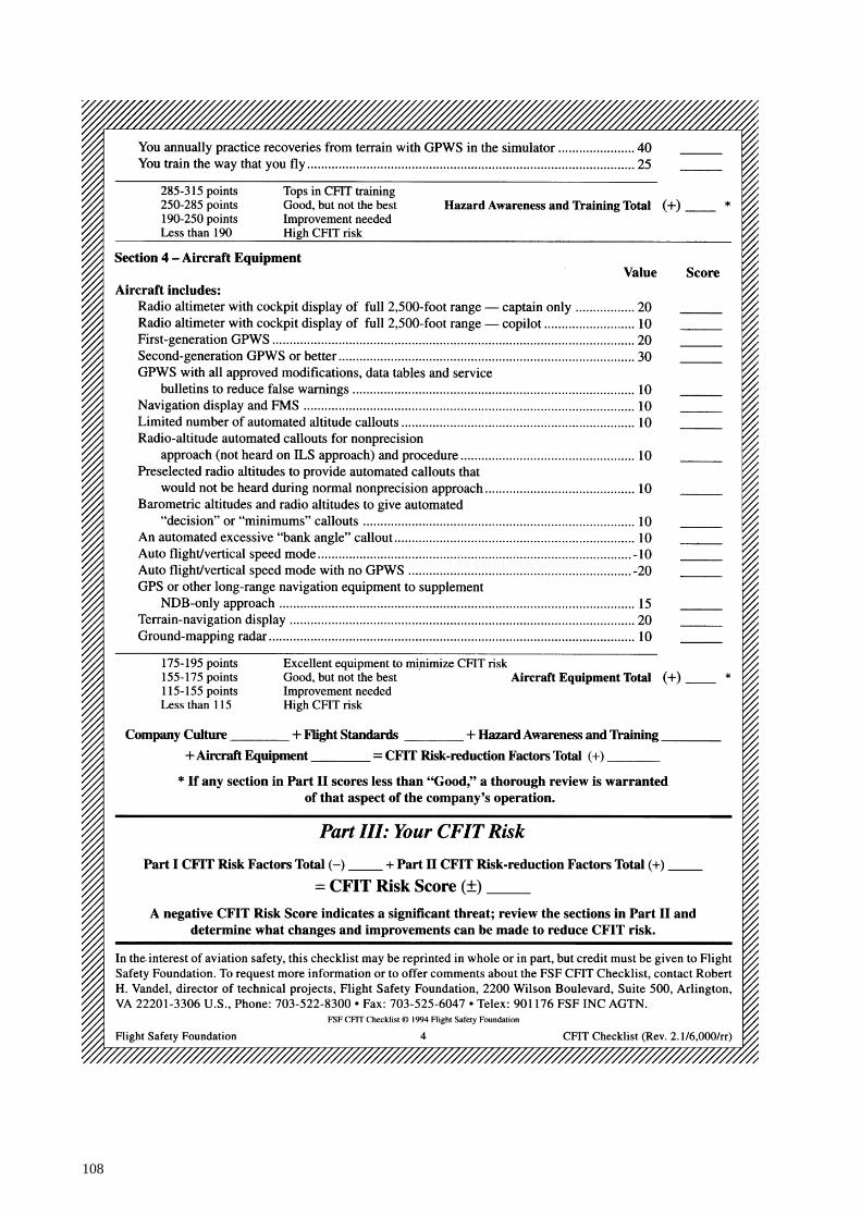
108

109
Appendix C
EDITED EXTRACTS FROM THE COCKPIT VOICE RECORDER TRANSCRIPT
Transcript of a Fairchild A-100 A cockpit voice recorder (CVR), s/n 51656, installed on a DHC-8 (Dash 8), ZK-NEY, which collided with terrain during an instrument approach to Palmerston North Aerodrome, on 9 June 1995.
LEGEND
AA Auckland OA Radio transmission from another aircraft ACC Area Control OH Ohakea AEV Aircraft’s “electronic voice” PM Palmerston North APP Approach Control A703 Ansett 703 CAPT Voice of Captain # Expletive FA Voice of Flight Attendant ------ Unintelligible word / words FO Voice of First Officer IDENT Morse code identification of radio navigation aid NP New Plymouth NOTE: Times are expressed in New Zealand standard time (NZST), UTC plus 12 hours, at the commencement of each voice recording.

110
Time & Source
INTRA-COCKPIT COMMUNICATION
Content
Time & Source
AIR-GROUND COMMUNICATION
Content Start of Recording
Start of Transcript
IDENT PM 08:52:14
dot dash dash dot, dash dash ( . - - . - - )
FO 08:52:19
Palmerston nav two on the one four eight no nav flags
CAPT 08:52:27
OK
FO A703 08:56:53
Ohakea Control Ansett seven zero three maintaining flight level two two zero received Palmerston Echo one zero one two
ACC OH 08:56:59
Ansett seven zero three Ohakea good morning, when ready descend to flight level one three zero, Palmerston weather Echo confirmed, I’ll advise if the zero seven approach is available
CAPT 08:57:08
one three zero
FO A703 08:57:10
wilco, flight level one three zero Ansett seven zero three, morning
CAPT 08:57:14
set and armed, ten thirteen still on the standby

111
Time & Source
INTRA-COCKPIT COMMUNICATION
Content
Time & Source
AIR-GROUND COMMUNICATION
Content FO 08:57:16
check
CAPT 08:57:18
I certainly hope it’s available, I don’t really want to do two five
FO 08:57:24
yeah
CAPT 08:57:24
I’ve done it once that was enough
FO 08:57:27
It’s quite a long way around there, isn’t it?
CAPT 08:57:28
yeah
CAPT 08:57:36
top of descent fifty four, visual or VOR depending on what we get, flap fifteen landing ninety five plus ten one oh five
FO 08:57:48
set
CAPT 08:57:49
that’s landing runway two five, seeing as it’s gusty, I’ll stick with flap fifteen
FO 08:57:55
yep

112
Time & Source
INTRA-COCKPIT COMMUNICATION
Content
Time & Source
AIR-GROUND COMMUNICATION
Content CAPT 08:58:04
and if we have to do the VOR DME runway zero seven second of March ninety five very similar to what you briefed, anticipating radar vectors or tracking via Ohakea, thence a radar heading for the final approach and inbound zero six nine not below fifteen hundred at nine miles not below seven thirty at seven miles, the descent profile three times minus three hundred down to four hundred and eighty feet QNH and sixteen hundred metres of vis requirement, and missed approach point two point five miles and the missed approach climbing left hand turn outbound two two nine and then back right hand to overhead into the holding pattern at fifty six hundred or as instructed
FO 08:58:47
check
CAPT 08:58:49
elevation one forty nine feet
FO 08:58:51
check
CAPT 08:58:55
and I’ll brief on the, other one if we actually have to do it
FO 08:58:58
yep
CAPT 09:02:29
and descent and approach checklist

113
Time & Source
INTRA-COCKPIT COMMUNICATION
Content
Time & Source
AIR-GROUND COMMUNICATION
Content FO 09:02:31
descent and approach checklist, cabin pressure
CAPT 09:02:33
set
FO 09:02:34
set, fuel panel
CAPT 09:02:36
is set
FO 09:02:37
set, check complete to altimeters
CAPT 09:04:50
leaving flight level two two zero on descent one three zero ten thirteen still on the standby
FO 09:04:54
check
CAPT 09:06:57
and MSA through here, in case I didn’t mention it, is eleven three hundred DME steps of forty five miles down to forty eight hundred fifteen miles to thirty six hundred
FO 09:07:04
check
ACC OH 09:07:06
Ansett seven zero three descend to five thousand feet radar terrain Ohakea QNH one zero one two

114
Time & Source
INTRA-COCKPIT COMMUNICATION
Content
Time & Source
AIR-GROUND COMMUNICATION
Content CAPT 09:07:11
five thousand on one two
FO A703 09:07:13
five thousand one zero one two Ansett seven zero three
FO 09:07:17
five thousand’s checked
FO 09:08:55
(yawn) oh gee, excuse me, I’m tired
OA 09:09:08
Ohakea good morning Airlink three one one flight level one eight zero copied Palmerston’s Foxtrot one zero one one
ACC OH 09:09:15
Airlink three one one Ohakea good morning when ready descend to flight level one three zero Palmerston weather Foxtrot confirmed
ACC OH 09:09:40
Airlink zero four eight Ohakea descend to four thousand feet Foxtrot confirmed
ATC OH 09:10:37
Ansett seven zero three stop descent at six thousand feet intercept the one four DME arc for the VOR DME approach runway two five
CAPT 09:10:44
#
FO A703 09:10:46
stop descent at six thousand intercept the one four DME arc for an approach to two five Ansett seven zero three

115
Time & Source
INTRA-COCKPIT COMMUNICATION
Content
Time & Source
AIR-GROUND COMMUNICATION
Content CAPT 09:10:53
six thousand check
ACC OH 09:10:53
Ansett seven zero three that’s correct, sorry the zero seven approach not available due departing traffic
CAPT 09:10:58
OK
FO A703 09:11:00
understood Ansett seven zero three
CAPT 09:11:02
OK six thousand
FO 09:11:03
check
CAPT 09:11:05
and the MSA on that part of the arc is fifty seven hundred, and
FO 09:11:13
did she say twelve or four, one four DME?
CAPT 09:11:15
well it’s a fourteen mile arc no matter what she said
FO 09:11:16
yeah it is isn’t it, yeah

116
Time & Source
INTRA-COCKPIT COMMUNICATION
Content
Time & Source
AIR-GROUND COMMUNICATION
Content CAPT 09:11:18
and coming in the one four eight left turn right hand arc fifty seven hundred until we’re through the zero five zero when it’s forty nine hundred
CAPT 09:11:35
and round we come lead in radial of zero six one and not interested in that holding pattern out there
FO 09:11:41
no
CAPT 09:11:42
inbound two fifty down the approach not below forty six hundred to start off with and not below three thousand at nine miles, not below seven, twenty five hundred at seven miles, and
FO 09:11:52
yep
CAPT 09:11:52
sixteen hundred at five
FO 09:11:54
make it a three times plus four hundred will we?
CAPT 09:11:56
eh?
FO 09:11:57
three times plus four hundred profile?
CAPT 09:11:58
that’s it

117
Time & Source
INTRA-COCKPIT COMMUNICATION
Content
Time & Source
AIR-GROUND COMMUNICATION
Content FO 09:11:59
yep
CAPT 09:12:00
and it’s right on the limits so we gotta stick to that
FO 09:12:03
yeah OK
CAPT 09:12:04
and non-standard procedure gear down flap fifteen at ten miles
FO 09:12:10
yeah
CAPT 09:12:12
I think that’s about all down, oh, minimums of six hundred and sixty feet
FO 09:12:15
yep
CAPT 09:12:17
and we’re through thirteen cleared to six, one zero one two twelve thousand three hundred sorry eleven thousand, two hundred and two oh fourteen knots
FO 09:12:29
checked, and transition level, altimeters
CAPT 09:12:32
check

118
Time & Source
INTRA-COCKPIT COMMUNICATION
Content
Time & Source
AIR-GROUND COMMUNICATION
Content FO 09:12:33
check, landing data
CAPT 09:12:34
checked and set
FO 09:12:35
checked and set, external lights (one chime)
FO 09:12:40
set and, anti-ice
CAPT 09:12:43
might as well have it on
FO 09:12:45
take it on
FO 09:12:49
anti-ice on and ignition normal ECU selected top check complete
CAPT 09:12:52
OK, both the ADF’s on Palmerston North
FO 09:12:55
and approaching the arc
CAPT 09:12:56
check, sixteen around we go left hand

119
Time & Source
INTRA-COCKPIT COMMUNICATION
Content
Time & Source
AIR-GROUND COMMUNICATION
Content IDENT
PM 09:12:58
dot dash dash dot, dash dash ( . - - . - - )
FO 09:13:04
and nav two course selector going to two five zero
CAPT 09:13:08
check
CAPT 09:13:24
and on the arc fifty seven hundred’s the minima
FO 09:13:34
yep
CAPT 09:13:57
and auto pilot’s disengaged
FO 09:14:01
yep
CAPT 09:14:04
you could set minimum descent altitude in the
FO 09:14:13
she hasn’t cleared us for the approach yet though has she, only cleared us to six thousand?
CAPT 09:14:16
but once you are on the arc I think the procedure is to

120
Time & Source
INTRA-COCKPIT COMMUNICATION
Content
Time & Source
AIR-GROUND COMMUNICATION
Content FO 09:14:18
I’ll just, I’ll just confirm it with her, will I?
CAPT 09:14:21
what?, I know we’re cleared to six
FO 09:14:24
yeah
CAPT 09:14:31
once you’re on the arc though you just set that thing to your minima, as far as I know
FO 09:14:35
she didn’t clear us for the approach though or anything, but
CAPT 09:14:38
no
FO 09:14:39
I’ll just
CAPT 09:14:40
I see what you mean
FO 09:14:41
yeah
FO A703 09:14:42
Ansett seven zero three is established on the arc descending to six thousand

121
Time & Source
INTRA-COCKPIT COMMUNICATION
Content
Time & Source
AIR-GROUND COMMUNICATION
Content ACC OH
09:14:47 Ansett seven zero three
CAPT 09:14:49
oh well
FO A703 09:14:50
just confirm we are to maintain six thousand
ACC OH 09:14:53
Ansett seven zero three affirm minimum descent on the arc is six thousand
CAPT 09:14:56
we’ve got fifty seven hundred
FO 09:14:58
yeah
CAPT 09:14:59
whatever, don’t argue
FO A703 09:14:59
understood Ansett seven zero three
CAPT 09:15:00
we won’t argue
ACC OH 09:15:04
Ansett seven zero three just confirming your descent is to six thousand feet

122
Time & Source
INTRA-COCKPIT COMMUNICATION
Content
Time & Source
AIR-GROUND COMMUNICATION
Content FO A703
09:15:05 descending to six thousand Ansett seven zero three
FO 09:15:10
(thats not right is it), cause passing zero five zero we can go to forty nine, or fifty hundred it is actually on the arc here
CAPT 09:15:18
yeah, we won’t argue
FO 09:15:22
No
FO 09:15:32
oh well I suppose we can be out there at fourteen DME at five thousand anyway
CAPT 09:15:38
mmm
ACC OH 09:15:51
Ansett seven zero three cleared VOR DME approach runway two five Palmerston QNH one zero one one
CAPT 09:15:56
zero one one
FO A703 09:15:57
cleared approach one zero one one Ansett seven zero three
FO 09:16:00
yeah now we’re right

123
Time & Source
INTRA-COCKPIT COMMUNICATION
Content
Time & Source
AIR-GROUND COMMUNICATION
Content CAPT 09:16:01
OK
FO 09:16:02
and I’ll set the MDA for you
CAPT 09:16:04
yep, that’s it, what ever it is, seven hundred
FO 09:16:06
six sixty, I’ll set seven hundred
CAPT 09:16:07
that’ll do
FO 09:16:10
and minimum descent altitude set
CAPT 09:16:13
check
FO 09:16:32
yep, and MSA here fifty seven hundred
CAPT 09:16:35
check
CAPT 09:16:52
oh of course we’ve got that strong south-westerly there

124
Time & Source
INTRA-COCKPIT COMMUNICATION
Content
Time & Source
AIR-GROUND COMMUNICATION
Content FO 09:16:56
say again?
CAPT 09:16:57
I’m just wondering why it tended to keep blowing out on the arc but of course there’s quite a strong south-westerly there
FO 09:17:02
yeah, yeah
CAPT 09:17:13
and I’m aware of the a limit of fifty seven hundred, (chime), even though there is no alert (chime)
FO 09:17:19
no
FO 09:17:35
oh you haven’t asked for those landing checks yet have you?, no
CAPT 09:17:37
no
CAPT 09:18:05
just about there
FO 09:18:07
fifty seven hundred until we cross the
CAPT 09:18:10
zero five zero

125
Time & Source
INTRA-COCKPIT COMMUNICATION
Content
Time & Source
AIR-GROUND COMMUNICATION
Content FO 09:18:11
zero five zero
CAPT 09:18:12
which is about almost
FO 09:18:14
just coming up to it
CAPT 09:18:15
that’ll do us, forty nine hundred now
FO 09:18:18
yep
CAPT 09:18:19
and not below forty six hundred till established inbound
FO 09:18:20
forty, forty nine yea now’s the MSA, commencing, and you can probably commence the approach at that out here
CAPT 09:18:27
yeah, yeah I guess so
FO 09:18:30
that’s about it
CAPT 09:18:35
what have we got fifty three hundred ten eleven and landing checks

126
Time & Source
INTRA-COCKPIT COMMUNICATION
Content
Time & Source
AIR-GROUND COMMUNICATION
Content FO 09:18:39
landing checks, belts smoking
CAPT 09:18:41
on
FO 09:18:42
synchrophasers off hydraulics chamber pumps checked on check complete to bleed air
CAPT 09:18:45
check
CAPT 09:18:51
there’s the lead in radial
FO 09:18:53
yep
CAPT 09:18:54
right hand on the inbound
FO 09:18:55
and course bar’s active
CAPT 09:18:57
check
CAPT 09:18:59
and going down to forty six hundred now

127
Time & Source
INTRA-COCKPIT COMMUNICATION
Content
Time & Source
AIR-GROUND COMMUNICATION
Content FO 09:19:20
thirty six, and twelve DME looking for four thousand
CAPT 09:19:26
check
CAPT 09:19:33
inbound no flags, no nav flags missed approach heading is, set, and that’s two fifty of course
FO 09:19:41
check
CAPT 09:19:42
and minimum descent altitude’s set
FO A703 09:19:47
Ansett seven zero three established inbound
ACC OH 09:19:50
Ansett seven zero three roger ten miles contact Palmerston Tower one two zero decimal six
FO A703 09:19:54
one two zero six at ten DME Ansett seven zero three
CAPT 09:20:06
gear down
FO 09:20:08
say again

128
Time & Source
INTRA-COCKPIT COMMUNICATION
Content
Time & Source
AIR-GROUND COMMUNICATION
Content CAPT 09:20:09
gear down
FO 09:20:10
oh, OK, selected
FO 09:20:14
and on profile, ten sorry hang on ten DME we’re looking for four thousand aren’t we, so a fraction low
CAPT 09:20:21
check
CAPT 09:20:25
and flap fifteen
CAPT 09:20:30
oh #
FO 09:20:32
actually no we’re not, ten DME we’re
CAPT 09:20:33
(whistle)
FO 09:20:34
# look at that
CAPT 09:20:35
I don’t want that

129
Time & Source
INTRA-COCKPIT COMMUNICATION
Content
Time & Source
AIR-GROUND COMMUNICATION
Content FO 09:20:36
no, # yeah that’s not good is it, so she’s not locked, so alternate landing gear
CAPT 09:20:42
alternate extension, you want to grab the QRH
FO 09:20:44
yep
CAPT 09:20:45
whip through that one, see if we can get it out of the way before it’s too late
FO 09:20:48
yeah, right
CAPT 09:20:52
and I’ll keep an eye on the aeroplane while you’re doing that
FO 09:20:54
yeah OK
FA 09:20:57
--------------------------
FO 09:21:01
yeah, we know
FA 09:21:02
thank you

130
Time & Source
INTRA-COCKPIT COMMUNICATION
Content
Time & Source
AIR-GROUND COMMUNICATION
Content FO 09:21:04
landing gear inop, landing gear malfunction, alternate gear eighteen, oh right, alternate gear extension, approach and landing checklist, pressurisation
CAPT 09:21:19
oh, just skip her down to the actual applicable stuff
FO 09:21:20
yeah, landing data altimeters tanks belt smoking OK airspeed below a hundred and forty knots
FO 09:21:26
and landing gear inhibit switch inhibit
CAPT 09:21:28
OK, and it’s one forty
FO 09:21:31
landing gear selector is down
CAPT 09:21:33
yep
FO 09:21:34
landing gear alternate release door fully open, which it is
CAPT
A703 09:21:38
and Ansett seven zero three established finals at Palmerston North

131
Time & Source
INTRA-COCKPIT COMMUNICATION
Content
Time & Source
AIR-GROUND COMMUNICATION
Content FO 09:21:41
yeah thanks, and insert
ACC OH 09:21:46
Ansett seven zero three that’s understood, and contact Palmerston Tower one two zero six
CAPT A703 09:21:49
one two zero six, thanks
FO 09:21:56
insert this handle, (horn)
CAPT 09:22:00
it’s noted
FO 09:22:01
insert handle at, till, oh yeah and operate until main gear locks, actually, nose gear
CAPT 09:22:15
you’re supposed to pull the handle, .... (laugh)
FO 09:22:16
yeah, it’s got it actually after that, yeah that’s pulled, here we go

132
Time & Source
INTRA-COCKPIT COMMUNICATION
Content
Time & Source
AIR-GROUND COMMUNICATION
Content AEV 09:22:25
terrain, whoop whoop pull-up, whoop whoop pull-up
09:22:30
(Sound of impact)
END OF ABBREVIATED TRANSCRIPT
END OF RECORDING.

133
Glossary of abbreviations used in this report
ACNZ Airways Corporation of New Zealand Limited ADI Attitude director indicator AGL Above ground level ALT-SEL Altitude Select amsl Above mean sea level AOM All Operator Message ASC Air Service Certificate ASMS Aviation Safety Monitoring System ATC Air Traffic Control ATCO Air Traffic Control Officer ATIS Automatic terminal information system ATP Acceptance Test Procedure ATPL (A) Airline Transport Pilot Licence (Aeroplane) ATS Air Traffic Service BAe British Aerospace BASI Bureau of Air Safety Investigation (Australia) oC Celsius CAA Civil Aviation Authority of New Zealand CAS Calibrated air speed CASO Civil Aviation Safety Order CEO Chief Executive Officer CFIT Controlled flight into terrain CG Centre of gravity CMM Component Maintenance Manual CRM Crew resource management CVR Cockpit Voice recorder DA Decision altitude DCA Director of Civil Aviation DFDR Digital flight data recorder DME Distance measuring equipment E East ELT Emergency location transmitter ETA Estimated time of arrival ETD Estimated time of departure FAA Federal Aviation Administration (United States) FAR Federal Aviation Regulation (United States) FD Flight Director FDAU Flight data acquisition unit FDR Flight data recorder FL Flight level fwd Forward

134
G Acceleration due to gravity GFR General Flight Report GPS Global Positioning System GPWS Ground proximity warning system hPa Hectopascals ICAO International Civil Aviation Organisation IFR Instrument Flight Rules ILS Instrument landing system IMC Instrument meteorological conditions kPa Kilopascals kg Kilogram(s) KLM Royal Dutch Airlines km Kilometre(s) LDG Landing LF Low frequency L/G Landing gear (Undercarriage) LLZ Localiser LOFT Line Oriented Flight Training Ltd Limited m Metre(s) oM Magnetic MAC Mean aerodynamic chord max Maximum MDA Minimum descent altitude METAR Aviation routine weather report (in aeronautical meteorological code) MHz Megahertz MK Mark MLG Main landing gear mm Millimetre(s) Mod Modification MSAW Minimum safe altitude warning system N North NASA National Aeronautics and Space Administration NDB Non-directional radio beacon nm Nautical miles No. Number NTSB National Transportation Safety Board (United States) NZALPA New Zealand Airline Pilots’ Association Industrial Union of
Workers Incorporated NZMS New Zealand Mapping Service map series number NZST New Zealand Standard Time (UTC + 12 hours) okta Eighths of sky cloud cover (e.g. 4 oktas = 4/8 of cloud cover)

135
PANS-OPS Procedure for air navigation services - operations PF Pilot flying PIC Pilot in command PM Palmerston North PNF Pilot not flying PSEU Proximity switch electronic unit psi Pounds per square inch QNH An altimeter subscale setting to obtain elevation above mean
sea level QRH Quick Reference Handbook RCC Rescue Co-ordination Centre Rev Revision RNZAF Royal New Zealand Air Force rpm revolutions per minute RTF Radio telephone or radio telephony S South SAR Search and Rescue SB Service Bulletin SIL Service Information Letter SOP Standard operating procedure SPAR Special aerodrome report SSR Secondary surveillance radar oT True TAS True airspeed TI Technical Instruction USA United States of America UTC Co-ordinated Universal Time VFR Visual Flight Rules VHF Very high frequency VMC Visual meteorological conditions VOR VHF omnidirectional radio range W West