REPORT 860 - CaltechAUTHORS
13
REPORT No. 860 ANALYSIS OF COOLING LIMITATIONS AND EF'FECT OF ENGINE-COOLING LWROVEAU3NTS ON LEVEL-FLIGHT CRUISING PERFORL~WNCE OF FOUR-ENGINE HEAVY BOMBER By FRANK E. MARBLE, ~IAHLOET A. ~IILLER, and E. BARTON BELL The I\~.C.~ has delleloped means, including an injection impeller and ducted head h f l e s , to improre the cooling charac- teetics of the SS60-cubieinchdisplacement radial engines installed in a four-engine h a z y bomber. The improrements afforded proper cooling of the rear-row exhaust-ualre seatsfor a wide range of ~(~101-jhp angles, mixture strength, and airplane speeds. The results offright tests maththis airplane are used a8 a ha& for a study to determine the manner and the eatent to which the airplane performance was limited by engine cooling. By means of this analysis for both the standard airplane and the airplane with engine-cooling modifiations, comparison of the specijc range at particular conditions and comparison of the cruising-performance limitations were made. The analysis of lerd$ight eruiaing performance of the air- plune urifh both the standard- and the modqijied-engine installu- Eions indicated that the maximum cruising economy is atiained at the minimum brake spee23c fire1 consumption when engine cooling under these conditions is possible. Operation at lean mixtures, high altitudes, and large gross weights m s limited for the standard airplane by engine cooling at the point where larger cowl-gap openings increase the power required for lerel flight at such a rate thut the additional cooling air amilable is imfiient to cool the engine when deceloping the additional power. 1T7hen cooling becomes impossible at the minimum brake speci'c fuel conaumptwn, the maximum cruising economy is obtained with a cowl-frap angle of approximately 6 ' and with the leanest mixture (abore the stoichiometric value) gi~ing satis- facdory engine cooling. Compa~ison of the calculated pet.fomanee of the atandard and the modified airplane indicated thut cooling improrements increased the marimurn spmj(;c range as much as 58 percent for operation where wide courb$ap angles and. enriched mixtures are required to cool the standard airplane. Corresponding increases in cruising range were calculated for$ights i n which conditiom allowing large increases in' cruising economy were encountered. The cooling improrements a l l m either an in- crease of more than 10,000 feet in operating alfitude at a giren airplane wight or a gross-weight increase of from 10,000 pounds af sea lerel to 86,000 pounds at all operating altz'tudes cabore 10,000 feet. INTRODUCTION Economical cruising operation of the four-engine heavy bomber has been impaired by the rich mixtures and the large quantities of cooling air required to cool properly the 3350- cubic-inch-clispIacement radial engines of this airplane. The cooling di€Eculties caused by nonuniform mixture distri- bution and poor cooling-air flom over the critical regions of the rear-row cylinders have resulted in frequent failure of the exhaust valve and the exhaust-valve seat. The difficulties experienced in cooling the ~shaust-ralve seats of the rear-row cylinders have been overcome to a con- siderable extent by improving the mixture distribution through applicat,ion of t.he injection impeuer (reference I) and by augmenting the flom of cooIing air to the critical temperature regions through insta1lat:ion of duct ed head baffles (reference 2). Flight tests of this airplane (reference 3) indicated that the temperatures of the exhaust-~alve seats on rear-row cylinders mere markedly lowered by these modi- .. fications and that airplane range, altitude, and gross weight preriously Limited by these temperatures could be greatly increased. Under most normal flight conditions, reasonable operating temperatures of the rear-row exhaust-valve sesh rere attained with the standard-engine installation for this airpIane onIy t.hrough use of large cowl-flap angles as well as enriched mixtures. The rear-row exhaust-valve seats of the modi6ed inst.allat.ion, however, were properly cooled over wide ranges of cowl-ff ap angles and mixture strengths, thereby affording the possibility of improving the airplane perform- ance through proper adjustments in cod-flap and mixture- control setting. Alt.hough the maximum performance &_.-. attained \here both fuel consumption and cowl-flap angle are reduced to minimum values, it is usually necessary to increase one mhan the other is decreased in order to avoid exceeding the limiting cylinder temperature. In order to use advantageously the improved airplane performance afforded by the engine modScations, t,he combination of cowl-flap angle and mixture str0ngt.h that gives the optimum cruising performance with proper cooling must be determined. The possibility of extended airplane performance formerly pro- hibited by cooling di€Ecultiesmust be investmigat-ed to e~aluate fully the effectiveness of the cooling improvement. Flight-test data of t.& four-engine heavy bomber obtained at the NACA Cleveland laboratory in 1944, are era.luated and analytically extended herein to shorn the effect of the injection impeller and ducted head baffles on the airplane performance. The relative effects of cowl-flap angle and specXc fuel consumption on the specific range of the air- 415
Transcript of REPORT 860 - CaltechAUTHORS

REPORT No. 860
ANALYSIS OF COOLING LIMITATIONS AND EF'FECT OF ENGINE-COOLING LWROVEAU3NTS ON LEVEL-FLIGHT CRUISING PERFORL~WNCE OF FOUR-ENGINE HEAVY BOMBER
By FRANK E. MARBLE, ~IAHLOET A. ~IILLER, and E. BARTON BELL
The I \ ~ . C . ~ has delleloped means, including an injection impeller and ducted head h f l e s , to improre the cooling charac- t ee t i c s of the SS60-cubieinchdisplacement radial engines installed in a four-engine h a z y bomber. The improrements afforded proper cooling of the rear-row exhaust-ualre seats for a wide range of ~(~101-jhp angles, mixture strength, and airplane speeds. The results offright tests math this airplane are used a8 a ha& for a study to determine the manner and the eatent to which the airplane performance was limited by engine cooling. B y means of this analysis for both the standard airplane and the airplane with engine-cooling modifiations, comparison of the specijc range at particular conditions and comparison of the cruising-performance limitations were made.
The analysis of lerd$ight eruiaing performance of the air- plune urifh both the standard- and the modqijied-engine installu- Eions indicated that the maximum cruising economy i s atiained at the minimum brake spee23c fire1 consumption when engine cooling under these conditions is possible. Operation at lean mixtures, high altitudes, and large gross weights m s limited for the standard airplane by engine cooling at the point where larger cowl-gap openings increase the power required for lerel
flight at such a rate thut the additional cooling air amilable i s i m f i i e n t to cool the engine when deceloping the additional power. 1T7hen cooling becomes impossible at the minimum brake speci'c fuel conaumptwn, the maximum cruising economy i s obtained with a cowl-frap angle of approximately 6' and with the leanest mixture (abore the stoichiometric value) g i~ ing satis- facdory engine cooling.
Compa~ison of the calculated pet.fomanee of the atandard and the modified airplane indicated thut cooling improrements increased the marimurn spmj(;c range as much as 58 percent for operation where wide courb$ap angles and. enriched mixtures are required to cool the standard airplane. Corresponding increases in cruising range were calculated for$ights i n which conditiom allowing large increases in' cruising economy were encountered. The cooling improrements a l l m either an in- crease of more than 10,000 feet in operating alfitude at a giren airplane wight or a gross-weight increase of from 10,000 pounds af sea lerel to 86,000 pounds at all operating altz'tudes cabore 10,000 feet.
INTRODUCTION
Economical cruising operation of the four-engine heavy bomber has been impaired by the rich mixtures and the large
quantities of cooling air required to cool properly the 3350- cubic-inch-clispIacement radial engines of this airplane. The cooling di€Eculties caused by nonuniform mixture distri- bution and poor cooling-air flom over the critical regions of the rear-row cylinders have resulted in frequent failure of the exhaust valve and the exhaust-valve seat.
The difficulties experienced in cooling the ~shaust-ralve seats of the rear-row cylinders have been overcome to a con- siderable extent by improving the mixture distribution through applicat,ion of t.he injection impeuer (reference I) and by augmenting the flom of cooIing air to the critical temperature regions through insta1lat:ion of duct ed head baffles (reference 2). Flight tests of this airplane (reference 3) indicated that the temperatures of the exhaust-~alve seats on rear-row cylinders mere markedly lowered by these modi-
.. fications and that airplane range, altitude, and gross weight preriously Limited by these temperatures could be greatly increased. Under most normal flight conditions, reasonable operating temperatures of the rear-row exhaust-valve sesh rere attained with the standard-engine installation for this airpIane onIy t.hrough use of large cowl-flap angles as well as enriched mixtures. The rear-row exhaust-valve seats of the modi6ed inst.allat.ion, however, were properly cooled over wide ranges of cowl-ff ap angles and mixture strengths, thereby affording the possibility of improving the airplane perform- ance through proper adjustments in cod-flap and mixture- control setting. Alt.hough the maximum performance &_.-. attained \here both fuel consumption and cowl-flap angle are reduced to minimum values, it is usually necessary to increase one mhan the other is decreased in order to avoid exceeding the limiting cylinder temperature. In order to use advantageously the improved airplane performance afforded by the engine modScations, t,he combination of cowl-flap angle and mixture str0ngt.h that gives the optimum cruising performance with proper cooling must be determined. The possibility of extended airplane performance formerly pro- hibited by cooling di€Eculties must be investmigat-ed to e~aluate fully the effectiveness of the cooling improvement.
Flight-test data of t.& four-engine heavy bomber obtained at the NACA Cleveland laboratory in 1944, are era.luated and analytically extended herein to shorn the effect of the injection impeller and ducted head baffles on the airplane performance. The relative effects of cowl-flap angle and specXc fuel consumption on the specific range of the air-
415

41 6 REPORT NO. 8 8 6 .-NATIONAL ADVISORY C O ~ ~ E E FOR AEROXAUTICS
plane with standard and modiiied engines are determined tls well as the combinations affording the maximum specific range. With the maximum specific range used as a crite- rion, the effects of the engine-cooling improvements on the specific range and the cooling limits of operation are com- puted. The calculations cover cruising conditions at alti- tudes from sea level to 35,000 feet and airplane weights from 75,000 to 150,000 pounds.
SYMBOLS. -
The folIo\i+g symbols are used in this report: A effective aspect ratio CD over-all drag coefficient . .
CD,, basic parasite-drag coefficient CL lift coefficient
.. . .
AP C',(Q) cooling-air pressuredrop coefficient, . 5pV2 Y
c brake specific fuel consumption, pounds per brake horsepower-hour
E specific range, miles per pouild of fuel A1 combustion-air mass. flow, pounds per second P power per cngine, brake horsepower Ap cooling-air pressure drop, inches of water
1 4 free-stream dynamic pressure, 2pT74, pounds per
square foot airplane level-flight cruising range, miles distance, miles cooling-air temperature ahead of engine, OF dective combustion-gas temperature, OF cylinder-head temperature, OF true airspeed, miles per hour airplane gross weight, pounds gross weight of airpIane without fuel, pou~~ds weight of fuel, pounds incremental drag coefficient resulting from cowl-flap
angle air density, slugs per cubic foot. .
air density (standard sea-level Arnly summer air, 0.00221), slugs per cubic foot
ratio of free-air density to standard-air density, plpo
apparent brake horsepower indicated airspeed, miles per hour cowl-flap angle, degrees
The subscript o represents sea-level refarence conditions.
ANALYSIS
The improvement in airplane cruising performance effected by cooling improvementa may be demonstrated by comparing cruising range and cooling-limited performance of standard- and modified-engine installations. This comparison requires that the conditions for best cruising economy, as weLl as the true nature of the limit.ations, be analyzed. In order to undertake this analysis with s a c i e n t accuracy and for a wide vmiety of airplane operating conditions, it is necessary
to investigate the relations among tlie airplane p~xforrnancc, the engine performance, t.he engine cooling characte~.ist.ics, and the associated variables. .-
AIRPLANE CBUISlNG RANGE
The specific range of an airplane, that is, t,hc distunc:c t.liat may be flown for each pound of fuel e.xpendcd at a given altitude, speed, and gross weight, may be exprcssd analytic- ally by
where the minus sign inclicatw that tllc fuel wcigllt decreases. during flight. Consequently, t.he range of t,he . -
airplane may be written as
where the integration covers weights from full to empty fuel supply. The variable of integration and the appro- priate limits may refer to eitl~er the fuel ~vcight or the gross airplane weight because thc variations of onc mo the same as those of the other if oil collsurrlption and abrupt changes of gross weight, sudl as disposnl of bombs, are neglected. The gross airpInne vrcigh~ is nioro convenient than the fuel weight innsmucl~ as it dircctly influences the specific range.
The most accurate evaluation of equation (2) rcquiros numerical methods because the cjuantitics affecting tho integranclvary with gross airplane wcight in ways that aro difficult to express analytically. Because of t hesa in tcr- relations, the specific range, and consequently tlle nirplalano cruising range, are functions of several rariables not all of which are independent. Both the gross weight of tho air- plane and the cruising altitude are usually fixed by conditiorls other than specific range. The optimum cruising conditions for any particular airplane weight and cruising aItiLude aro therefore the vaIues of the remaining variables thal givo the integial in equation (2) a masimum value and at the aame time provide proper cooling.
SPECIFIC RANGE
Method of solution.-In order to calculate the spccifio range of the four-engine heavy bomber, it was neccssnry to have ih either analytical or grnphical form t,he aerody- namic characteristics of t-he. airplane, tlic engine oporating performance, and the engine cooling requirements. Thcse variables-are not independent but are related through the requirements that the engine be properly cooled and that the airplane be maintained in level flight.
For a given altitude and gross airpla.ne weight, tho &sical relations among the variables that define tlic specific rango are :
I. Power required by the airplane for steady level ilightdetermined by the airpIane speed and tIie cowl-flap opening

EFFECT OF ENGINE-COOLING IMPROIEMENTS OM CRUISING PERFORMANCE OF HEAVY BOMBER 417
2. Cooling-air pressure drop required to cool the engine to the limiting head temperature-determined by the engine pan-er output and the brake specitic fuel consump tion
3. Cooling-air pressure drop available across the engine (necessarily equal to the pressure drop required x hen operating a t the limiting head temperature)- determined by the airplane speed and the coml- flap opening
Together with the dehition of specific range, these relations form a set of four simultaneous aIgebraic equations in six variables. Four of these variabIes can therefore be eIimi- na'ted and the cruising economy e-qressed in terms of any two. The airpIane speed and the brake specific fuel ~onsumpt~ion aro considered the independent variables and the masimurn values of specific range with respect to these variables are determined by graphical means.
Assumptions for calculations.-The analysis was based on standard Army summer air c~ndit~ions and on the conserva- tive temperature limit of 580' F a t t.he exhaust-valve seat (corresponding to a limit between 420' and 440' F at t.he rear spark-plug gasket of the standard engine) of the hottest rear- row cylinder. I t was assumed that limiting exhaust-valve- seat temperatures would not be encountered on the front-row cylinders where the critical regions are more adequately cooled. The relation between the engine speed and the en- gine power mas taken to be a propeller-Ioad cume (fig. 1) detined by the rated engine conditions. The resulting indi- cated mean effective pressures were below the knock limit for all fuel-air ratios. For operation along t,he propeller-load curve, the relation between brake speci6c fuel consumption and fueI-air ratio (k. 2) mas approximated from £Light-test rauIts and from estimates of the engine manufacturer. The analytical performance comparison for the airplane with standard- and modified-engine installations shouId be materially undected by t,he appro-ximate nature of this re- lation because brake horsepowers above the normal rated 2000 for the engine were not used in the cdculations.
RELATLOKS M O K Q FUNDAMENTAL VAEIABLES
The formulation of the relathions affecting the airpIane cruising economy necessitates analysis of these flight ta ts . Each of the three fundamental relations be considered separately.
Brake horsepower required.-An analyt,icaI approximation of the brake horsepower required for level Eght may be found when the reIation between the lift and t.he h a g coeffi- cients of the airplane are knom. If the airplane is considered an elliptically loaded wing of £init.e span (reference 4), the drag co&cient may be expressed as t,he sum of the parasite and the induced drag coeiEcients
26CW
e 2 4 0 0
8 22200
8 u 2000
-S b
It300
1 6 0 0 h h 6W7 800 ICXW 1200 /W 16m 1800 2iZO 2m 2400
Engine power, bhp
prow^ 1.-Relation beheen engine porn and engine speed corresgorng to PfOPeIIn- l a d eurre b w d on rated engine mnditiom.
and t,he t,rue parasite drag of the cowl flaps. The coefficient was based on a ~g area of 1750 square feet. Numerical values of the parasite drag coefficient with closed cowl flaps C D , , , , and t,he effective aspect ratio of the equirdent cllipti- cally loaded -wing A, as ell as the relation between the incremental drag coefEcient and the cowI-flap angIe, can be determined.
In order to obtain values of t.he u n k ~ o ~ v n quantit,ies of equation (3), a limited number of Eght tests ~ 5 t . h the air- pIane mere undertaken in which airspeed, aItitude, and other pertinent fight data were accurately measured. The brake horsepower mas determined on two of the four radial engines of 3350-cubic-inch displacement from torquemeter readings and mas estimated for the other two engines from carefully observed engine operating conditions. The weight of t.he airplane was appro-ximated from the knotvn weight of the empty airplane and the approximated weight.s of equipment, personnel, and fuel a t the particular time of test.
The method of relating the power requirements to the lift and drag coefficients is well known and i ts applicat.ion to tmhe generalization of flight-test data is thoroughly discussed in references 5 and 6. The linear relation between the over-all drag coefficient (dosed coml flaps) and the square of the lift coefficient was determined from flight tests a t
I Fue/-air r o fio where the ineremental drag coefEeient 4 4 ) accounts for the
e-Appmxtmate dtlon of tnra ,--sh na ol lnesar addit.iond drag resdting from the cooling-air momentum loss ratto ior various e w e speed=.
418 REPORT NO. 860.-NATIONAL ADVISORS COMBlITTEE FOR AERONAUTICS
two engine speeds for an assumed constant propulsive efficiency of 0.85 and is shown iu figure 3. Because of this assumption and because the airplane weight was not pre- cisely known, the data for the different engine speeds ar.0 not in complete agreement but d e h e two p d e l lines. The approximat-ion used in the following analysis was made by drawing a line parallel to and equidistant from the lines defined by aach set of points, .The experimental values of the basic parasitodrag coefficient and the effective aspect ratio may be determined from figure 3 and equrttion (3) as
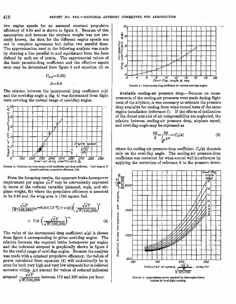
The relation between the incremental drag coefficient a(+) and the cowl-flap angle t$ (fig. 4) mas determined from night tests covering the normd range of cawl4ap angles.
F l a m 3.-Relation betiwen square of llft weIIlcient and drag coet6clent. Cowl flaps at 2" (closed) position; propulslra efficlenoy, 0 . 1 .
From the foregoing results, the apparent brake-horsepower requirement per engine GP may be conveniently expressed in terms of the reduced variables (airspeed, mph; and a.k- plane weight, 1b) where t-he propulsive efficiency is assumed to be 0.85 and the wing area is 1750 square feet
The value of the increment.al drag coefficient 4 4 ) is chosen from figure 4 corresponding to given cowl-flap angles. The relation between the required brake horsepower per engine and the indicated airspeed is graphically shown in figure 5 for the useful range of cowl-flap angles. Because the analysis mas made with a constant propulsive efficiency, the values of power calculated from equation (4) will undoubtedly be in error for both very high and very low airspeeds but is believed accurate within f 3 percent for vdues of reduced indicated
7--
airspeed d'V between 170 and 230 miles per hour. ~w/100,00-d
Cow/-f/cp ong/e. q!, deg
F ~ a u a ~ 4.-Incremental drag mfldent for VEXIOUB cowl-flap angles.
Available cooling-air pressure drop,-Because no meas- urements of the cooling-air pressures were made during flight tests of the airplane, i t was necessary to estimate tllo prcssure drop available for cooling from wind-tu~lncl ksts of t.he samo engine installation (reference 7). If tlie effects of inclinatiotl of the thrust axis and of air compressibility are neglected, thc rdation between cooling-air pressure drop, airplano spccd, and cowl-flap angle may be expressed as
where the cooling-nir pressure-drop coefficient. C,(+) depends only on the coal-flap angle. The cooling-air prcssurc-drop coacient was corrected for wind-tunnel wall iritcrfcrenco by applying the correction of reference 8 to t h e pressure down-
Indico f e d .a
Waca~ 6.-ApgroxlmaLe power requimd by fouraqhe hcsvy bombex for level-Qht erulsing.

EFFECT OF ENGINE-COOLING IMPROVEMENTS ON C ~ I S I N G PERFORMANCE OF HEAVY BOMBER 419
F~ccae 6.-Varlatlon of caolhg-afr presmedmp eoefident wtth mwl-hp 8ngIe. (Data from reference 7, corrected for whd--el KalI fnterferenee.1
stream of the engine rather thm to t.he pressure a t the corn-1-
flap exit. The resulting corrected values of are shorn ;ipVT
in figure 6 for the useful range of cowl-flap angles. Engine cooling characteristics.-The cooling data from
flight tests of the airplane with standard- and modified- engine installations mere correlated in the manner of refer- ence 9, lising the relation given in @re 6 for estimating the cooling-air pressure drop. The flight tests undertaken for this purpose and the details of t-he correlation procedure are discussed in reference 3. Because dXEculties have been ex- perienced in cooling the exhaust-valve seats of t.he rear-row cylinders and because the coohg limitations are prescribed by the temperature of the hottest cylinder, the cooling rela- tions are based on the maximum temperatures of the rear- row exhaust-valve seats. The correlated results of the W t tests of the stand~rd-engine installation and of tmhe modxed
E~CUBE 7.-CompIL12Mn between crowletion d ooolhg data for standard and modi&d engines inpat hboardnsoelledaIrpIane, bwd ontemperatnntof West rear-mwerbaust- d v e sear
installation using the SAGA injection impeller and ducted head b d e s on all rear-row cylindeis are shonn in figure 7. The follovSng relations between the maximum temperature of the rear-row exhaust-~alve seat and the engine operating conditiolls re re found to apply for the standard engine in- stallation
Th- Ta ~ f O . 6 0 -- 0.82 T,- Th- ( u p ) O."
and for the modsed engine installation incorporating the injection impeller and ducted head bafles
The variation of the effective combustion-gas temperature 115th fuel-air ratio (reference 10) is shon-n in figure 8 at n car- buretordeck temperature of 0" F. Because the engine in- corporates a geared supercharger, the effective gas tempera- ture also depends on engine speed, and consequently curves are given for three engine speeds. The value of the effective gas temperature given by figure 8 must be increased by 0.80
Overw/ / fue l -a i r raf io . .
Frocse 8.-Relatlon of eErctive combustion-gss temperature to or& fuel& rat10 fw standard engine. Carbaretwdeck temperature, O0 I?. (Data from reference lo.)
of the carburetordeck temperature in degrees Fahrenheit when applying the cmes .
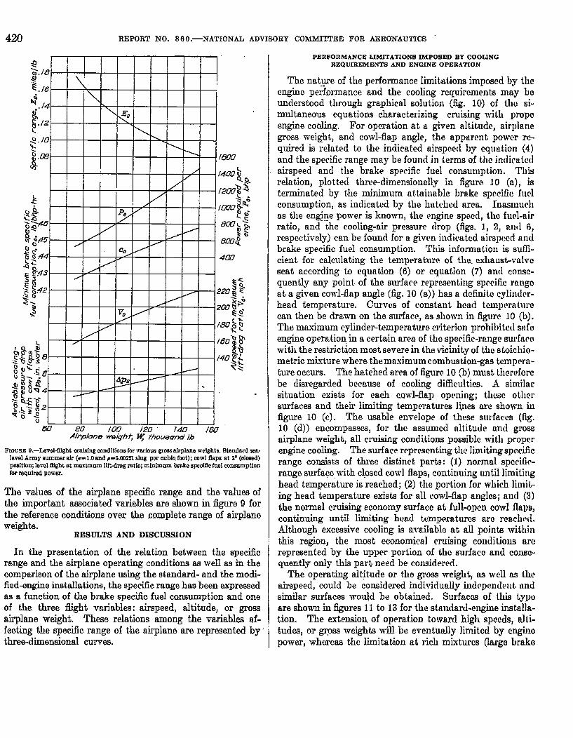
Nondimensiond form of results.-In order to present the results nondimensionally, a set of reference conditiok that vary only with airplane weight 1vas chosen for convenience. On the assumption that the turbosupercharger maintains sea-level back pressure at all times, the following reference conditions correspond closely to those providing the masi- mum specific range for a particular airplane weight if the engine temperature limit is disregarded:
1. Standard sea-level Army summer air: c=1.0 and p=0.00221 slug per cubic foot
2. Con-1 flaps a t 2' (closed) position 3. Level £light a t maximum lift-drag ratio
. 4. Minimum brake specific fuel consumption for required power
The power required for sea-level fight a t maximum lift-drag
i ratio, and consequent.ly the minimum brake specific fuel ~onsumpt~ion (condition 4), varies only with airplane weight.
420 REPORT NO. 8 6 0.--NATIONAL ADVISORY C O M M I ~ E E FOR AERONAUTICS
-
w7 80 /CM 120 74.0 /60 A l ip l~ne we&hf, fhownd 16
for regdred power. 1 ra.nge surfaw witah closed cowl flaps, continuing until limiting
PERFORMANCE LIMITATIONS IMPOSED BY COOLING REQUIREMENTS AND ENGINE OPERATION
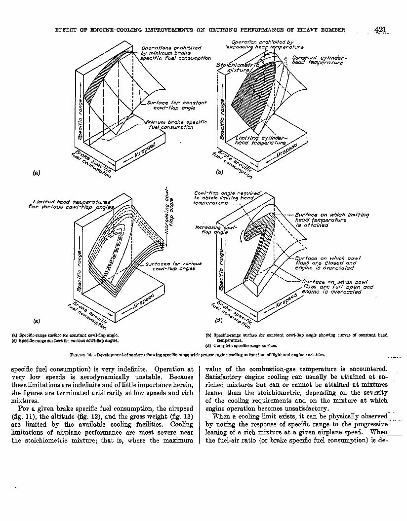
The nat.;re of the perfoimance limitations imposed by the engine performance and the cooling requirements mny bo understood through graphicnl solution (fig. 10) of thu si- multaneous equations characterizing cruising with propc engine coclling. For operation a t a given altitude, airplnnc gross weight, and co~vl-flap angle, t.he apparent powcr re- quired is related to the indicated airspeed by equat.ion (4) and the specific range may be found in terms of t,hc indicate(] airspeed and the brake specific fuel consunlpt.ion. This relation, plotted three-dimensionally in figure 10 (a), is terminated by the minimum at.tainablc brake specific fllcl consumption, as indicated by the hatched arcn. Inas~nucll as the engine power is known, the engine speed, the fucl-nir mtio, and the cooling-air pressure drop (figs. 1, 2, and 0, respectively) can be found for a given indicated airspi!cd ~1 ld brake specific fuel consumption. This i~lformat.ion is suffi- cient for calculating the temperature of the cxhrtust-valve seat according to equation (6) or equation (7) and consc- quently any point of the surface representing spccific rnngo a t a given cowl-flap angle (fig. 10 (a)) has a dcfinitc cylintlcr- head temperature. Curves of constant hcud tml~c~ra t~ l rc can the11 be d r a m on the d a c e , as sllown in figure 10 (b). The mcximum cylinder-temperature criterion prohibitctl stt f u engine operation in cb certnin ares of tho specific-range surfacc! wit11 the restriction most severe in the vicinity of the stoichio- metric mixture where themaximum combustion-gas tempcrn- ture occurs. The hatched area of figure! 10 @) must t.hcrcforc be disregarded because of cooling difficu1ti.a. X similar situation exists for each cowl-flap oprning; thcsc otllcr surfaces and their limiting temperatures lines arc shown in figure 10 (c). The usable envelope of these surfaces (fig. 10 (d)) encompasses, for the assumccl nltitudc and gross airplane weight, all cruising conditions possiblc with propcr
Ftoo~s o.-Level-uht cr~aondIt ionsforvarlous grwalr~lane weights. Btandard see level Army summer air (u-1.0 and p-0.mn slug pcr cubia foot); wwl &ps at a0 (cIc#d) rmaltion;level m ~ h t at marlmnm ratlo; mi&nrn speolftefnd
The values of the airplane specific range a.nd the vdues of the important associated variables are shown in figure 9 for the reference conditions over the complete range of airplane weights.
RESULTS AND DISCUSSION
engine cooling. The surface representing tlir. limiting &ccific- range coqsish of . - three - - distinct - - parts : (1) . . normal . - - . specific- . .
In the presentation of the relation between the specific range and the airplane operating conditions as well as in the comparison of the airplane using the standard- and the modi- fied-engine installations, the specific range has been expressed as a function of the brake specific fuel cansumpt.ion and one of the three flight variables: airspeed, altitude, or gross @lane weght. These relations among the variables af- fecting the specific range of t.he airplane are represented by' three-dimensional curves.
head temperature is reached; (2) the portion for which lilrlit ing head temperature exists for all cowl-flap anglcs; and (3) the normal cruising economy surface at full-opcn cowl flaps, continuing until limiting head temperatures nrc rcacl~cci. Although excessive cooling is arailable a t all points within this region, t.he most ecorlomical cruising conditiolls arc represented by the upper portion of the surfacc and come- quently only this part need be considered.
The operating altitude or the gross weight, as well aa thc. airspeed, could be considered individually indcpnndelit and similar surfaces would be obtained. Surfaccs of Lhis typo are shorn in figures 11 to 13 for the standa~d-engine installa- tion. The extension of operation toward high spccds, alti- tudes, or grpss weights will be eventudly limited by cngino power, whereas the limitation at rich mixtures (lnrgo Lralio
EFFECT OF ENGINE-COOUNG INPROVEMBNTS ON CRUISING PERFORMANCE OF HEAVY BOMBER . 421.
Svfoce for constant cowl- flap angle
C m f o n f cy/inder- head tempemtrrre
(a) Speclllorange wvfnce fa eonstant cowl-flap angle. (a) B p e c ~ g e surfaces for wrtm cowl-flap angles.
@I 8peclllc-m.w sariace far mnstant cowl-bp angle a h o m c u r ~ e s d constant head temperature.
(d) Complete speclfIc-xmge s n r h .
Frocss 10.-Development of sarEBces showing ape& rsnge with proper engine cooling as fnnction of U h t and engine ~srfables. . . .-
specific fuel consumption) is very indehite. Operation at very low speeds is aerodynamically unstable. Because these Lidations are indefmite and of little importance herein, the figures are terminated arbitrarily a t Iow speeds and rich mixtures.
For a given brake specSc fuel consumption, t.he airspeed (fig. l l ) , the altitude (fig. 12), and the gross weight (flg. 13) are limited by t he availabIe cooling facilities. Cooling limitat,ions of airplane performance are most severe near the stoichiometric mixture; that is, where the maximum
value of the combus tion-gas temperature is encountered. Satisfacto~y engine cooling can usually be attained a t en- riched mixtures but can or cannot be attained at mixtures leaner than the stoichiometric, depending on the severity of the cooling requirements and on the mkture a t which engine operation becomes unsatisfactory.
'iThen a cooling limit exists, i t can be physically obsemed - . .
by noting the response of speczc range to the progressive leaning of a rich mixture a t a given airplane speed. When the fuel-air ratio (or brake specific fuel consumption) is de-

REPORT NO. 8 0 0.-NATIONAL ADF'LSORY C O m m E E FOR AERONAUTICS
FIGURE 11.-Effect of airspeed and brake speciflcfuel consumption on speciec range with cowl flaps set for proper engine cooling. Standard-engine Installation; airplane aelght, 100,000 pounds; altitude, MMO feet.
creased, the cowl flaps must be opened to retain proper engine cooling. At some particular cowl-flap setting, depending on the indicated airspeed, a greater cowl-flap angle necessi- tates such a large increase in engine pawar that the cooling- air pressure drops required are greater than those available from the increased cowl-flap angle. An example of this cooling limit occurs in figure 11 a t an indicated-airspeed ratio of 1.30. Continuous leaning of .the mixture is therc- fore impossible and t,he additional cowl-flap opening has only decreesed the specific range a t the same mixture and airplane speed. Although successful airplane operation and engine cooling can be accomplished a t cowl-flap angles greater than those occurring a t the cooling-limited perform- ance, increased fuel consumption and sacrifice in specific range results. Such conditions of operation are of no practical importance.
DETERMINATION OF MAXIMUM SPECIFIC RANGE
For a given airplane weight and operating altitude, it
appears from figure 11 that proper enginc cooling rntty he attained a t a variety of airspeeds, mixtures, and cowl-llap angles. The combination of these variables nffurclinp tho most desirable cruising perfol-nlance must bc uscd as a guidc to the proper flying conditions and to servc as a busis of comparison for the standard- and the modificd-mgino installations. The masimum spec.ific range a.as consi~lc~rcd the gorerniug factor for level-flight conditions; ho\t-cvc~, h order to investigate the essential charactwistics of tho specific range a t various airspeeds, determinat.ion of i.110 maximum specific range is considered in two part,: (1) proper combination of cowl-flap angle and mixture strcngt-11, and (2) most economical airplane speed.
optimum combination of cowl-flap angIe and mixture strength.-The results of the analysis relating spcc!ific: rango and cooling requirements fall into two clnsscs, diflrrentiatccl by ~vhet.her cooling is possible a t rnixtures leaner tllun tile stoichiometric. The distinction is not conwxncd, ho\vevcr, with cooling a t the sloichiomotric mixture.
Frccm 12.-Effeect of alrglene altitude and brake specific fuel consumplion on sperifle m e with cowl h p s set for prop= engine mllng. Standardanglne Instellstbn; Indlosteb- airspeed ratlo, 1.00, airplane weight, 100,000 pounds.

EFFECT OF ENGINE-COOLING IhlPROF'EMEXTS ON CRUISWG PERFORMANCE O F HEAVY B O B E B
Typical examples of the h t case, where coohg is possible a t mixtures leaner than the stoichiometric, are shown in figure 11 by the cross sections at indicated-airsped ratios
T ' of 1.00 and 1.15. Under these conditions, the greatest
specific range for a given airspeed is always attainable at the minimum brake specsc fuel consumption eren though ap- preciable cod-flap angles are required; the cowl-flap angle generally appears to be of less importance than the mixture strength. This result does not preclude the possibility of cooling improrements (such as changes in baffle configura- tion) that increase the specific range by decreasing the required cowl-flap angle for a given brake spec5c fuel consumption.
T7 I .
The second case in figure 11, section at 1&F=1.30,
concerns the optimum cruising conditions when proper engine cooling is impossible near, or leaner than, the stoichiometric mixture. Rich mixtures are essentially inefficient and can usually be avoided by reducing the airplane speed or altitude. When it is necessary to operate under circumstances requiring a rich mixture, both fuel-air ratio and cowl-flap angle must- be considered because reducing the fueI-air ratio to the mini- mum raIue for which cooling is possible requires large cowl- flap angles and effects considerable loss in spec& range. Although the maximum specific range occurs a t widely Merent mixture strengths depending on the airplane speed, altitude, and meight, the cod-flap angle for maximum specXc range for rich-miyture operation is usually between 4' and 6 O . Inasmuch as the specsc range is insensitive to small changes in mixture strength in the, neighborhood of the maximum value, setting the cowl flap at approximately 5 O and leaning the mixture until the limiting head temperat ure is encountered appears to be a reasonable procedure for appro-ximating the maximum specific range.
Indicated airspeed.-The airspeed leading to the ma-dmum specXc range for a. given altitude and airplane weight will be investigated in two cases depending, like the opt.imum com- hination of cowl flap and mixture, on nhether engine cooling is possible a t mixtures leaner than stoichiometric.
If proper coohg is attained a t mixtures leaner than stoichiometric, the maximum specific range is always (for a given airplane weight and altitude) achieved at t-he airplane speed providing the madmum lift-clrag ratio. The maximum ralue of specific range shown in figure 11 is of this nature. Deviations of the conditions for specsc range from the mini- mum brake specific fuel consumption the ma-imum lift- drag ratio are small if the propuIsive efficiency is assumed constant.
When satisfactory engine cooling is impossible at mixtures leaner than stoichiometric, the maximum specific range may occur either at t,he velocity giving the maximum lift-drag ratio and an enriched. mixture or a t an airplane speed (and engine power) sdEcient1-y below that giving masirnun lift-
FIGGEE l2.-EBeat ddrplane weight and Brake apeciEc fueI comum~tion on spedao ranye d t h mwl fhps set for proper en&e cooling. S ~ - e n ~ Installation; fndlmted-ak- speed ratk, 1m altitude. EOOJ feet.
clrag ratio to allow engine cooling in a lean condition. The reduction of airspeed below that giving maximum lift-drag ratio is generally prohibited by the tenclency of the airplane to attain trim at either of the two airspeeds (fig. 5) cor- responding to the given power. For comparison, it is assumed t.hrrt airplane operation at mmimum lift-drag ratio is satisfactory but that lower speeds are unsatisfactory. Consequent-ly, under the foregoing assumption, t h e maximum specific range lvill be attained at the maximum lift-drag ratio and the optimum cowl-flap and mixture settings for both lean and rich operating mixtures.
PERFORMANCE WITH 1-MPROVED COOLING CEUBACTERISTICS
The improvement in engine cooling characteristics result- ing from use of the NACA injection impeller and ducted head bames on t.he rear-row cylinders permitted a general increase in specific range because of the smaller cowl-flap angles and leaner mixtures required for proper cooling. The operating alt'itudes and the airplane weights for which proper

REPORT NO. 8 6 0.-NATIONAL ADVISORY COW!M'EE FOR AERONAUTICS
c.ooling is possible a t lean mixtures were indicated to be greatly extended. Comparison of specific range for various airspeeds, operating altitudes, and yeights are given in figwes 14, 15, and 16, respectively.
Specific range and cruising range.-For operating condi- tions at which proper coohg was possible with amall cowl- flap angles for the standard airplane, only mal l improve- ments in the specific range are shown for the modified airplane because the colvl-flap losses aro quite mall in this range. For conditions where the standarc1 airplane required large cowl-flap angles, the improvement in the specific range is quite great, attaining its maximum value in the vicinity of the cooling-limited performance of the standard engine. The percentage improvement in specific range resulting from the use of the NACA injection impeller and ducted head baf3es is summarized for various airspeeds, a.ltitudes, and airplane weights in the following table: .. ..
r ImposaIble to malntdn valve-seat tempcmturo M o w MOW F w1th slbndmdcnglne Installation.
Tha maximum specific range of the instttlltltion with thc standard and the modified engine was dcterminrd for widc ranges of airplane weights and operatirlg nltiludcs. Inns- much as the masimum specific range is a frxnction of uld,lr two vaeables, the maximnm specific: rmgc for the st.undard- . -. .

EFFECT OF ENGINE-COOLING IMPROVEL4XKTS ON C R U m T G PERFORMANCE OF HEAVY BOMBER 425
' - - Modified engine ip* l la f i~5 --- Wa&ar~I engine tnsfal/af wns
FIQUBE 16.-Effects of akplane welght and brake spectea fuel eonsumption an s g e m p e with standard- and wIth modllted-englne LnstaIIatloas. Oowl fips set for grogm enpine COO- Indfeated-ahpeed ratio, 1.03 dtlw, llWO feet.
and the modXed-engine installations has been plotted in figure 17 against airplane reight for ~arious altitudes. The discont.inuities that occur at certain altitudes are caused by the t.ransit,ion from lean to rich mixtures when lean operation becomes impossible.
The curves of figure 17 ha\-e a simple and useful interpre- tation in terms of the level-flight cruising range of the air- plane. In accordance ~ 5 t h equat,ion (Z), the airplane range may be expressed as
where E(urn3 is the specific range a ~ d a b l e for an airplane of weight TTT and flying a t an altitude corresponding to the density ratio u. The limits of the integral indicate that the integration extends from the weight of the airplane mi th fuel to the weight of the airplane x3.h all fuel expended. For a given altitude, the value of this integral corresponds to the area under the curve (fig. 17) for the appropriate altitude
taken between abscissa values of We and Tre+ T I > During the flight, values of the instantaneous specXc range increase as the total m e g h t of the airplane decreases. The calculat,ion of the level-hht 'crui~ing range is therefore a simple matter for m y particular set of conditions. Values of the airplane range computed in this manner are approximate and do not account for the fuel expended in t,ake-off, climb, and lerel fight at conditions other than optimum. .
(a) Ghndord-engfne lnstalhtloa (b) 36odiBed-engfne ~ t I o n I I
FIGGEE 17.-Variation of martmum s p d c rsnge with gross adght for &plane at se~eral altitudes.
426 REPORT KO. 8 6 0.-NATIONAL ADYLSORY COMMITTEE FOR AERONAUTICS
(a) S t a n d a r d ~ e bsblletion. (b) Modlfled-engine installath.
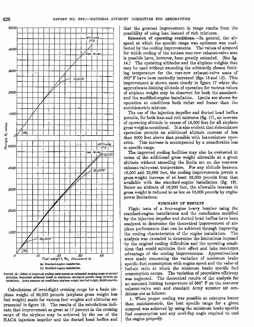
PIGWEE 18.-Effect of irnpmved d f n g pfrfmmanoe on e s t b t e d aulsingrange at several altltndes; theoretiaal estlmats based on maximum calanlsted speciec range for both in- stallatlons. Amy aummer air conditions; airplane weight less fuel weight, 80,000 gonnds.
Calculations of level-flight cruising range for a basic air- plane weight of 90,000 pounds (airplane grass weight less fuel weight) made for vmious fuel weights and altitudes are presented in figure 18. The resulta of the calculations indi- cats that improvement as great as 17 percent in the cruising range of the airplane may be achieved by the use of the MACA injection impeller and the ducted head baffles and
that the greatest improvement in range results from the possibility of using lean instead of rich mixtures.
Extension of operating conditions.--In gencral, the air- speed a t which the specific range was optimum was ntlaf- fected by the cooling improvements. The valucs of airspert1 for which cooling of the hottest rear-row exhustvalve sent is possible have, however, been greatly extended. (Scc fig. 14.) The operating altitudes and the airplnno wcighh tllnt may be used without exceeding thc arbitrarily chosen limit- ing temperature for t he rear-row exhaust-vnlve scat8 of 560'3' have been markedly increased (figs. 15 and 10). This improvement is sho~vn more clearly in figure 17 whcrc tllc approximate limiting altitude of operation for various ~nlucs of airplane weight may be olsel.ved for both the stmdard- ancl the modified-engine installation. Limits arc show11 for operation at conditions both richer and lcancr than tht! stoichiometric mixture.
The use of the injection impeller and ducted head baMrv permits, for both lean and rich mixtures (fig. 17), an incrcasc of operating altitude in excess of 10,000 feet for all airplnno gross meights considered. It is also evident Bat rich-mixture operation permits an actditional altitude incrcasc of lcqs
than 5000 feet above that possible with lean-mixturo oprr- ation. This increase is accompanied by a considcrablo Ioss in specific range. Th improved cooling facilities may also be cvaluatcd in
terms of the additional gross weight allowable at a giver1 altitude without exceeding the limia set on tho rcnr-row exhaushalve-seat temperature. For any altitude bolrvccn 10,000 and 25,000 feet, the cooling improvements pe~mit a gross-weight increme of at least 35,000 pounds from that available with the standard-engine instdation (fig. 18). Below an altitude of 10,000 feet, the a l lo~~~ul le increase in gross weight is reduced to as low as 10,000 porinds by engine power limitations.
SUMhlARY OF RESULTS Plight tests of a four-engine heavy bomber using the
standard-engine instalIations and the i~lstt~llation mortified by the injection impeller and ducted. hcad Lames have hce11 analyzed to determine the theoretical itnprovrmcnt of air- plane perfo~mance that can he achieved tllrougli improving the coolmg characteristics of the engine instalIation. 'I'ht! analysis was extended to determine the limitations imposctl
.by the original cooling difficulties ancl thc opcrati~~g condi- tiom that would minimize their effect and take maximurn advantage of the cooling improvements. Approximat ions were made concerning the variation of luinimi~m brakc specific fuel consumption w i t h engine speed and the valur of fuel-air ratio a t which the minimum brnkc spccific: futhl consumption occura. The variation of 1)roj)ulsive &ci~ncy was neglected. The theoretical results of khc analysis for an assumed limiting temper~ture of 560' F on thc rear-row exhaust-valve seat and standard Army wmmcr air con- ditions are as follows:
I. When proper cooling was possible a t rnixturrs lcnncr than stoichiornetric, the best specific rango for a given airspeed mas achieved by using the minimum brakc specific fuel consumption and any cowl-flap angle required to cool the engine properly.

EFFECT OF EJSGINE-COOLING IMPROVEMENTS ON CRUISING PERFOFtMAMCE OF HEAVY BOMBER 427
2. When proper cooling was impossible at mixtures leaner than stoichiometric, the best specific range for a given air- speed was achieved by using a cod-flap angle of approxi- mateIy 5' open and the leanest mixture that allows proper cooling.
3. The meximum airpIane specific range (and, conse- quently, the ma-ximum cruising range) was always attained wit.h the appropriate mixture-cowl flap combination and an airspeed corresponding to the maximum lift-drag ratio, if the airplane flying altitude was stabIe at this point.
4. For flying conditions at which the specific range of the standard airplane is seriously reduced by large c o o k re- quirements, engine-ins tallat ion analysis indicated that the specific range was, in an extreme case, increased as much as 38 percent though use of engines empIoying the injec- tion irnpeIIer and ducted head baffles.
5. Analysis of flight-test data indicated that improvement in engine cooling perfolmance though use of the NACA injection impeller and ducted head baffles allowed an increase in operating altitude in excess of 10,000 feet or a gross-weight increase of from 10,000 pounds at sea Ierel to at least 35,000 pounds above 10,000 feet x-ithout exceeding an e.&aust- valve-seat temperature of 560' F.
REFERENCES
1. Marble, Frank E., Ritter, Filliam K., and Miller, MaNon' A.: Effect of NACA Injection Impeller on Mixture Distribution of Double-Row Radial Aircraft Engine. NACA Rep. hTo. 821, 1946.
2. Sipko, Michael A., Cotton, Charles B., and Lusk, James B.: Cse of Ducted Head BafBes to Reduce Rear-Row Cylinder Tempera- tures of an Air-Cooled Aircraft Engine. PI'ACA T N No. 1053, 1946.
3. Marble, Frank E., JLiller, Mahlon A., and VenseI, Joseph R.: Effect of NACA Injection Impeller and Ducted Head Baffles on Flight Cooling Performance of DoubIeRow Radial Engine in Four-Engine Heavy Bomber. NACA JIR KO. E5D13, . h y Air Forces, 1945.
4. Kerber, L. V.: Induced Drag and Equiralent 1Ionoplane &pect Ratio. VoL V of Aerodynamic Theory, div. 0, oh. 11, sec. 3, W. I?. Durand, ed., JuLius Springer (Berlin), 1935, pp. 230-232.
5. Reed, Albert C.: Airplane Performanoe Testing a t Altitude. Jour. Aero. Sci., voL 8, no. 4, Feb. 1941, pp. 135-160.
6. Men, Edmund T.: Flight Testing for Performance and Stability. Jour. Aero. Sci., rol. 10, no. 1, Jan. 1943, pp. 1-24; disoussion, pp. 26-30.
7. Wyatt, DeJIarquis D., and Conrad, E. Killiam: An Investigation of Corrl-Flap and Cod-Outlet Designs for the E 2 9 Poi ie~Plant , Installation. NACA 31R KO. E5K30aJ Army Air Forces, 19-46.
8. Katzoff, S., and Finn, Robert S.: Determination of Jet-Boundary Corrections to Cowling-FIapOutlet Pressures by an Electrical Analogy Method.. NACA ARR No. 4B23, 1944.
9. Pinkel, Benjamin: Heat-Transfer Processes in Air-Cooled Engine Cylinders. NACA Rep. No. 612, 1938.
10. Pinlcel, Benjamin, and Rubert, Kennedy F.: Correlation of Wright Aeronautical Corporation Cooling Data on the R-336G14 Inter- mediate Engine and Comparison meth Data from the Langley 16-Foot High-Speed TunneI. NACA ACR No. E5A18, 1946.