REPLACEMENT OF SPARES - Shriman Power ACB... · REPLACEMENT OF SPARES It is recommended that all...
19
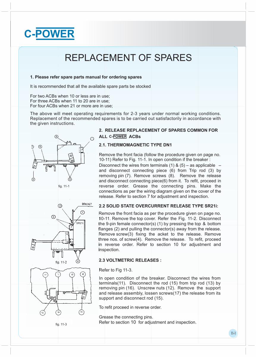
1 1 1 REPLACEMENT OF SPARES It is recommended that all the available spare parts be stocked For two ACBs when 10 or less are in use; For three ACBs when 11 to 20 are in use; For four ACBs when 21 or more are in use; 1. Please refer spare parts manual for ordering spares 2. RELEASE REPLACEMENT OF SPARES COMMON FOR ALL ACBs 2.1. THERMOMAGNETIC TYPE DN1 Remove the front facia (follow the procedure given on page no. 10-11) Refer to Fig. 11-1. In open condition if the breaker : 2.2 SOLID STATE OVERCURRENT RELEASE TYPE SR21i: 2.3 VOLTMETRIC RELEASES : Refer to Fig 11-3. 11-1 fig. 11-1 fig. 11-2 fig. 11-3 Disconnect the wires from terminals (1) & (5) – as applicable – and disconnect connecting piece (6) from Trip rod (3) by removing pin (7). Remove screws (8). Remove the release and disconnect connecting piece(6) from it. To refit, proceed in reverse order. Grease the connecting pins. Make the connections as per the wiring diagram given on the cover of the release. Refer to section 7 for adjustment and inspection. Remove the front facia as per the procedure given on page no. 10-11. Remove the top cover. Refer the Fig. 11-2. Disconnect the 9-pin female connector(s) (1) by pressing the top & bottom flanges (2) and pulling the connector(s) away from the release. Remove screw(3) fixing the acket to the release. Remove three nos. of screw(4). Remove the release. To refit, proceed in reverse order. Refer to section 10 for adjustment and inspection. In open condition of the breaker. Disconnect the wires from terminals(11). Disconnect the rod (15) from trip rod (13) by removing pin (16). Unscrew nuts (12). Remove the support and release assembly, lossen screws(17) the release from its support and disconnect rod (15). To refit proceed in reverse order. Grease the connecting pins. Refer to section 10 for adjustment and inspection. The above will meet operating requirements for 2-3 years under normal working conditions. Replacement of the recommended spares is to be carried out satisfactorily in accordance with the given instructions. SR21i
-
Upload
truongdiep -
Category
Documents
-
view
231 -
download
2
Transcript of REPLACEMENT OF SPARES - Shriman Power ACB... · REPLACEMENT OF SPARES It is recommended that all...
1
1
1
REPLACEMENT OF SPARES
It is recommended that all the available spare parts be stocked
For two ACBs when 10 or less are in use;For three ACBs when 11 to 20 are in use;For four ACBs when 21 or more are in use;
1. Please refer spare parts manual for ordering spares
2. RELEASE REPLACEMENT OF SPARES COMMON FOR
ALL ACBs
2.1. THERMOMAGNETIC TYPE DN1
Remove the front facia (follow the procedure given on page no.10-11) Refer to Fig. 11-1. In open condition if the breaker :
2.2 SOLID STATE OVERCURRENT RELEASE TYPE SR21i:
2.3 VOLTMETRIC RELEASES :
Refer to Fig 11-3.
11-1
fig. 11-1
fig. 11-2
fig. 11-3
Disconnect the wires from terminals (1) & (5) – as applicable – and disconnect connecting piece (6) from Trip rod (3) by removing pin (7). Remove screws (8). Remove the release and disconnect connecting piece(6) from it. To refit, proceed in reverse order. Grease the connecting pins. Make the connections as per the wiring diagram given on the cover of the release. Refer to section 7 for adjustment and inspection.
Remove the front facia as per the procedure given on page no.10-11. Remove the top cover. Refer the Fig. 11-2. Disconnect the 9-pin female connector(s) (1) by pressing the top & bottom flanges (2) and pulling the connector(s) away from the release. Remove screw(3) fixing the acket to the release. Remove three nos. of screw(4). Remove the release. To refit, proceed in reverse order. Refer to section 10 for adjustment and inspection.
In open condition of the breaker. Disconnect the wires from terminals(11). Disconnect the rod (15) from trip rod (13) by removing pin (16). Unscrew nuts (12). Remove the support and release assembly, lossen screws(17) the release from its support and disconnect rod (15).
To refit proceed in reverse order.
Grease the connecting pins. Refer to section 10 for adjustment and inspection.
The above will meet operating requirements for 2-3 years under normal working conditions. Replacement of the recommended spares is to be carried out satisfactorily in accordance with the given instructions.
SR21i

1
1
1
2.4 AUXILIARY CONTACT BLOCK:
(For both 2N/O + 2N/C & 6N/O + 6N/C) Disconnect the connections. Lossen the screws and remove the auxiliary contact block. To refit, proceed in reverse order, make sure rotary switch link is placed properly Make the connections as per the wiring diagram shown in Section 13 and the ferrules attached.
2.5 MOVING SECONDARY ISOLATING CONTACT BLOCK :
Disconnect the wires.
Remove screws(1).
To refit proceed in reverse order. Make the connections as per the wiring diagram shown in Section 13.
2.6 FIXED SECONDARY ISOLATING CONTACT BLOCK:
Remove wire cover by unscrewing screws(1).
Disconnect the wires.
To refit, proceed in reverse order.
Make the connections as per the wiring diagram shown in Section 13.
3 CN-CS 3200, CN-CS 1600D, CN-CS 3200H0/H1 & CN-CS 4000 H0/H
3.1 ARC CHUTE :Press latching lever (1) and rotate it. Remove the arc chute by pulling it upwards.
To refit, place the arc chute over the arcing horns(2) and rotate the latch for locking.
. REPLACEMENT OF SPARES FOR CN-CS 630C TO
11-2
Fig. 11-4
Fig. 11-5
Fig. 11-6
Fig. 11-7

1
1
1
3.2 ARCING CONTACTS
3.2.1 FIXED ARCING CONTACT :
3.2.2 MOVING ARCING CONTACTS :
11-3
Fig. 11-8
Replacement of fixed arcing contacts is to be done in OPEN condition of the breaker. Loosen the screws(1) and slide the arcing contacts forward. To refit, proceed in reverse order.
Replacement of moving arcing contacts is to be done in CLOSED condition of the breaker. Loosen the screws (2) by about 1.5 mm to disengage locating boss(E) and then pu l l upwards. To refit, proceed in reverse order.
NOTE : Spare kits accompany detailed instructions on HOW
TO CONNECT & TEST a particular accessory.

1
1
1
OVERALL DIMENSIONS
DIMENSIONAL DETAILS FOR FIXED BREAKERS
For 630A to 3200A 3P/4P C/H
RatingsCN-CS
Dimensions(mm)
A D E F
630/800/1000A C/H 3P
1250/1600A C/H 3P
630/800/1000A C/H 4P
C/H 4P1250/1600A
2000/2500A C/H 3P
2000/2500A
3200A C/H 3P
C/H 4P
3200A C 4P
326 57 102
414
482
628
56
83
82
98
154
150
98
156
-
-
630/800/1000/1250/1600 C/H
2000/2500/3200 C/H
Terminal Connections
Note : All Dimensions are in mm.
12-1
1(2
)
61
10
4
39
0
34
9 61
6 MIN3
26
A 6 mi .3 n
2 4685 26
DD E F E
Terminal for 630/800/1000C/H Terminal for 1250/1600/ 2000/2500/3200 C/H, 3200 H1/4000H
50
3
FOR METALLIC COMPONENTS
356 min.
FOR INSULATING SHEET16 max.
DOOR
BEZEL
27
10
0 m
in.
200
min
.71
25
22
33
27 20
230
444
EARTHING TERMINAL
2 HOLES - O6.3
2.6
140min.
85
54
10
68
.82
58
200
min
.
27
TO REMOVE ARC CHUTE
22
7
10
14
5
10
23.5
15
15 23.5
22
7
14
0
1
1
1
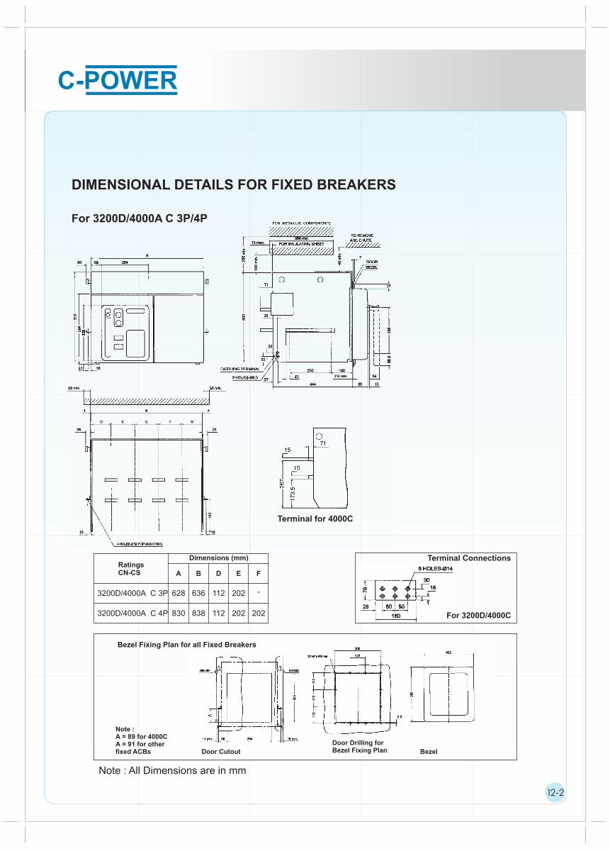
DIMENSIONAL DETAILS FOR FIXED BREAKERS
For 3200D/4000A C 3P/4P
Terminal for 4000C
Terminal Connections
For 3200D/4000C
Bezel Fixing Plan for all Fixed Breakers
Note :A = 89 for 4000CA = 91 for otherfixed ACBs Door Cutout
Door Drilling forBezel Fixing Plan Bezel
12-2
RatingsCN-CS
Dimensions (mm)
A B D E F
3200D/4000A C 3P
3200D/4000A C 4P
628 636 112 202 -
830 838 112 202 202
Note : All Dimensions are in mm

1
1
1
DIMENSIONAL DETAILS FOR DRAW-OUT BREAKERS
For 640A to 3200A C/H 3P/4P, 3200H1/4000H 3P, 630A to 3200A S1 3P/4P
*Terminal For 630/800/1000 C/H/S1, 1250/2500S1 & 2000C/H
*Terminal for 3200H1/4000H
*Terminal forfor 3200C/H/S1
*Terminal for1250/1600/2500 C/H & 1600/200S1
12-3
7DOOR
BEZEL
25
66
8.8
(10) 54
Dimensions (mm)RatingsCN-CS A D E F
630/800/1000A C/H/S1 2000A S1
1250/1600A C/H/S1
630/800/1000A C/H/S1 2000A S1
1250/1600A C/H/S1
2000/2500A C/H2500A S1
3200A C/H/S1
2000/2500A C/H2500A S1
3200A C/H/S1
3200A H0/ H1
3200A H0/ H1
4000A H0/ H
4000A H0/ H
399
487
555
701
701
909
97.5
96.5
123.5
122.5
148.5
102
98
154
150
202
-
98
-
156
-
Note : All Dimensions are in mm.
151.5 202 202
3P
3P
4P
4P
3P
3P
4P
4P
3P
3P
4P
4P
1
1
1
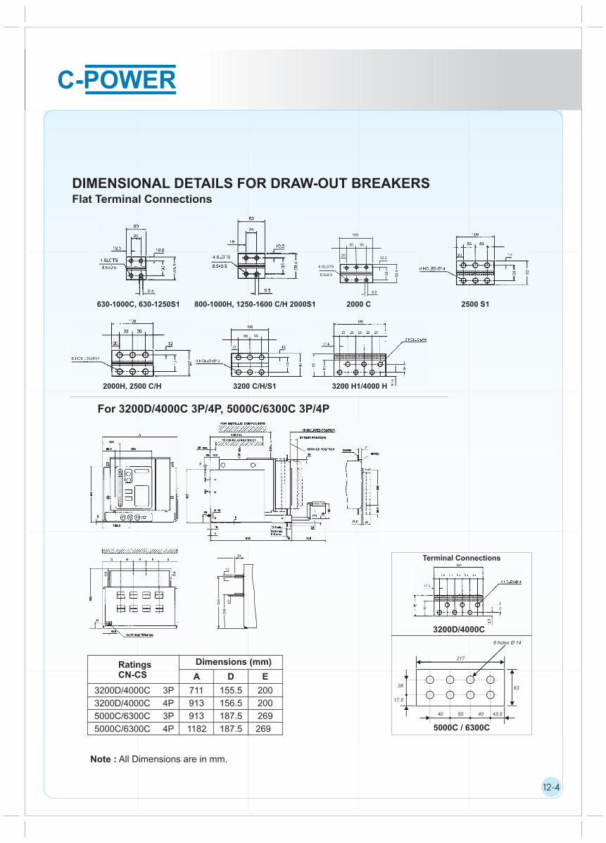
DIMENSIONAL DETAILS FOR DRAW-OUT BREAKERS
Note : All Dimensions are in mm.
Flat Terminal Connections
630-1000C, 630-1250S1 800-1000H, 1250-1600 C/H 2000S1 2000 C
2000H, 2500 C/H 3200 C/H/S1 3200 H1/4000 H
For 3200D/4000C 3P/4P, 5000C/6300C 3P/4P
28
17.5
40 50 40 43.5
63
217
8 holes Ø 14
Terminal Connections
4000C
5000C / 6300C
12-4
3200D/4000C
36
8
54
25
6
15
5
100
30 30
20
6 SLOTS
8.5x9.5
10.2
8.5
58
.4
38 38 62
2500 S1
RatingsCN-CS
Dimensions (mm)
A D E
3200D/4000C 3P
3200D/4000C 4P
5000C/6300C 3P
5000C/6300C 4P
711 155.5 200
913 156.5 200
913
1182 269
187.5
187.5
269

1
1
1
DIMENSIONAL DETAILS FOR DRAW-OUT BREAKERSMounting Details :- For Horizontal Mounting of all Draw-out Breakers
Bezel Fixing Plan for all Draw-out Breakers
Door Cutout Door Drilling forBezel Fixing Plan
Bezel
For 4000A C 3P/4P, 5000C/6300C 3P For 630A to 3200A C/H 3P/4P, 3200 H1/4000 H 3P
Note : For 4000A C 3P/4P, 5000C/6300C 3P ACB, A=81.5 For other Drawout Breakers A=79.5
/4P
12-5
Type G(mm)
800 to 1600 C/H 3P
630 to 2000S1 3P
800 to 1600 C/H 4P
630 to 2000S1 4P
2000/2500 C/H 3P
2500/3200S1 3P
2000/2500 C/H 4P
2500/3200S1 4P
3200H0/H1 3P
3200H0/H1 4P
4000H0/H 3P
4000H0/H 4P
5000C/6300C 3P
5000C/6300C 4P
280.3
280.3
368.3
368.3
436.3
436.3
582.3
582.3
582.3
790.3
582.3
790.3
863
1132
Note : All Dimensions are in mm
1
1
1
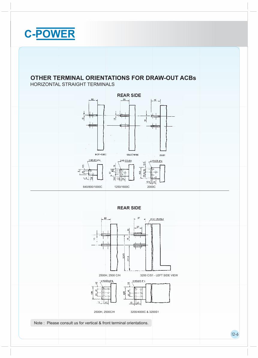
OTHER TERMINAL ORIENTATIONS FOR DRAW-OUT ACBsHORIZONTAL STRAIGHT TERMINALS
REAR SIDE
Note : Please consult us for vertical & front terminal orientations.
REAR SIDE
12-6
640/800/1000C 1250/1600C 2000C
10
2500H, 2500C/H 3200/4000C & 3200S1
2500H, 2500 C/H 3200 C/S1 - LEFT SIDE VIEW
1
1
1
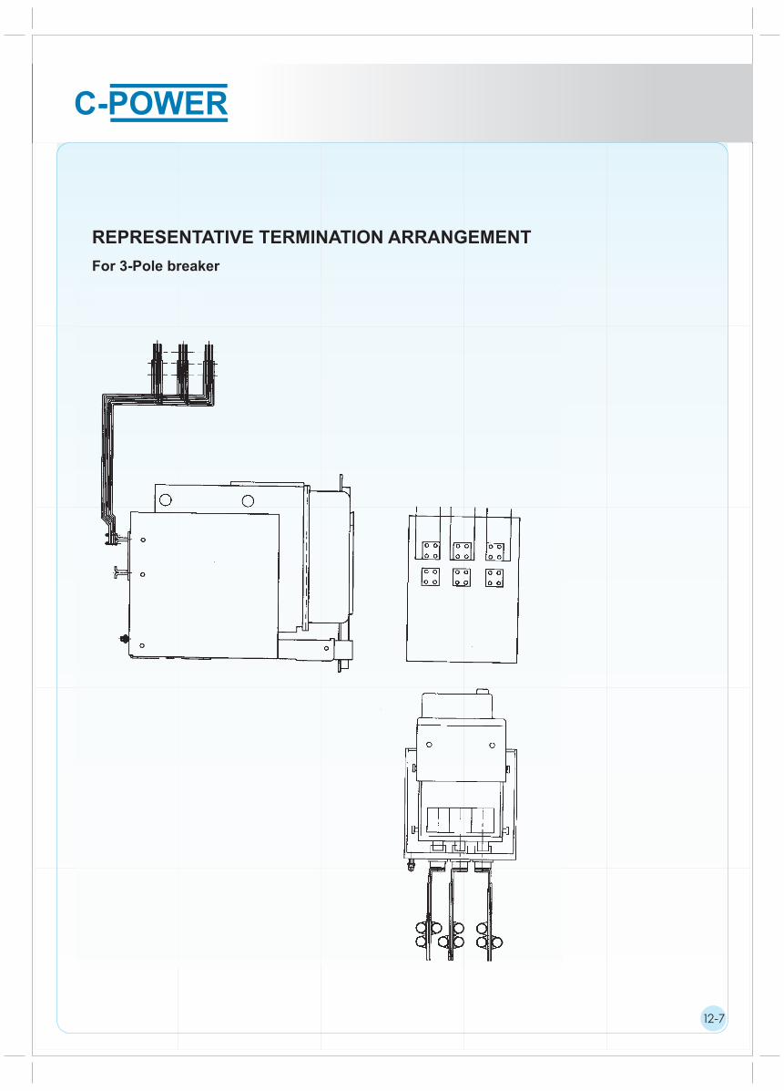
REPRESENTATIVE TERMINATION ARRANGEMENT
For 3-Pole breaker
12-7
1
1
1
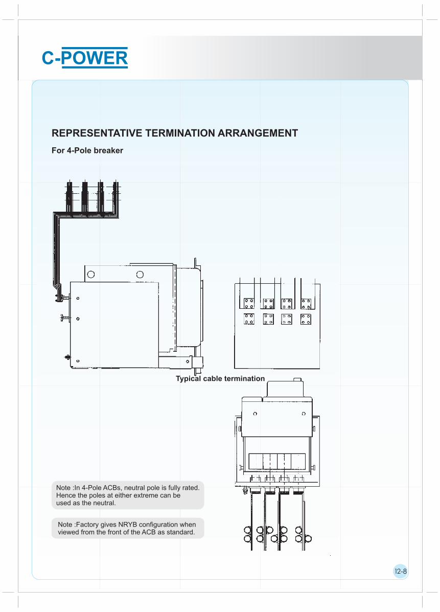
REPRESENTATIVE TERMINATION ARRANGEMENT
For 4-Pole breaker
Typical cable termination
Note :In 4-Pole ACBs, neutral pole is fully rated.Hence the poles at either extreme can be used as the neutral.
12-8
Note :Factory gives NRYB configuration whenviewed from the front of the ACB as standard.

1
1
1
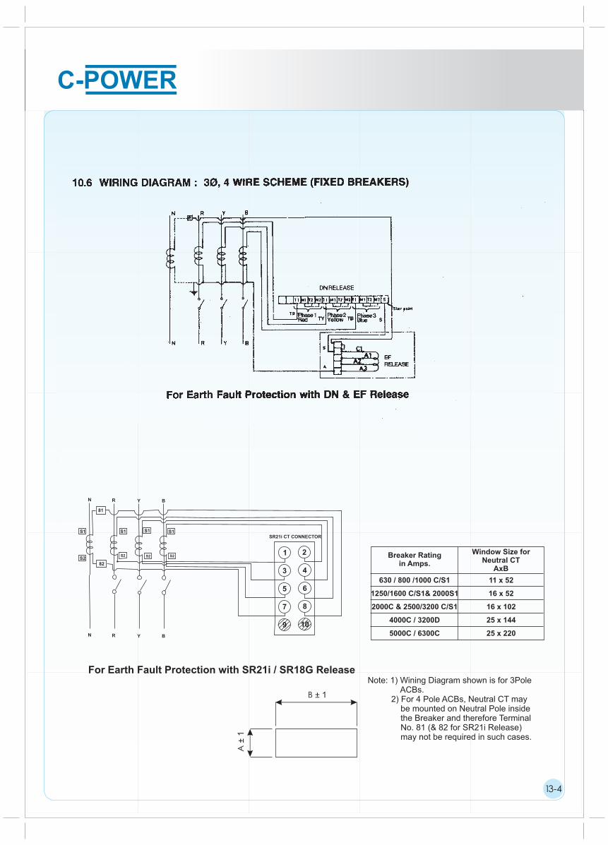
WIRING DIAGRAMS
FOR ELECTRICALLY OPERATED ACBS
AC CONTROL SUPPLY
DC CONTROL SUPPLY
E,B,D,C,A : SIC Termination. A,B,C,D & E are 3,40,41,42 SICs used for internal wiring in electrically operated ACBs.
N,H,4 : Internal Termination points...... : Wiring to be done by the Customer : Internal Wiring
EE : ‘Closing’ electromagnet
M : Motor
C6 : Service Position Microswitch for Withdrawable Circuit Breaker (shown in ‘Test’ Position)
C11 : Limit Switch (Operates when closing electromagnet is held ON)
R : Economy resistor
FCA : Limit Switch (Shown in Spring Charged Condition)CA : Auxiliary Contacts (Shown in Breaker Open Position)
NOTE :*CA1 N.O. Contacts 3 & 4 not available for auxiliary use, if shunt release type EA/EA1 is used**SIC-A
Programmed to complete the circuit only in ‘Test’ position. This enables carrying out operations of breakers by bypassing the electrical interlocks which are active in ‘Service’ position.Max 24 SICs available on ACB (For control, accessories and auxiliary circuits)
SERVICETEST
13-1
1
1
1
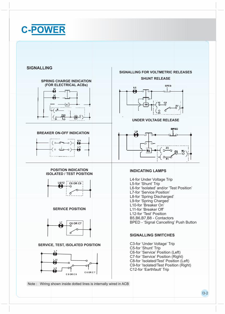
SIGNALLING
SPRING CHARGE INDICATION(FOR ELECTRICAL ACBs)
SIGNALLING FOR VOLTMETRIC RELEASES
SHUNT RELEASE
BREAKER ON-OFF INDICATION
UNDER VOLTAGE RELEASE
POSITION INDICATIONISOLATED / TEST POSITION
SERVICE POSITION
SERVICE, TEST, ISOLATED POSITION
INDICATING LAMPS
L4-for Under Voltage TripL5-for ‘Shunt’ TripL6-for ‘Isolated’ and/or ‘Test Position’L7-for ‘Service Position’L8-for ‘Spring Discharged’L9-for ‘Spring Charged’L10-for ’Breaker On’L11-for ‘Breaker Off’L12-for ‘Test’ PositionB5,B6,B7,B8 - ContactorsBPED - ‘Signal Cancelling’ Push Button
SIGNALLING SWITCHES
C3-for ‘Under Voltage’ TripC5-for ‘Shunt’ TripC6-for ‘Service’ Position (Left)C7-for ‘Service’ Position (Right)C8-for ‘Isolated/Test’ Position (Left)C9-for ‘Isolated/Test Position (Right)C12-for ‘Earthfault’ Trip
Note : Wiring shown inside dotted lines is internally wired in ACB
13-2
L6/12 C8 OR C9
L7 C6 OR C7
L 7
L 12
L 6
C 8 OR C 9C 6 OR C 7

1
1
1
SIGNALLING FOR OVERLOAD AND SHORT - CIRCUIT TRIPPING
Manual Reset
The cancelling of the fault signal is effected by pressing the local trip button, which also resets the overcurrent release.
Auto Reset
Cancelling of fault signalling is provided by push button BPED. The presence of the fault signal does not prevent closing of the circuit breaker.
Common SignallingCommon Signalling
Separate Signalling
Signalling Switches
C1-for ‘Overload and Short Circuit’ TripC2-for ‘Short Circuit’ Trip
INDICATING LAMPS
L1-Common for ‘Overload and short Circuit’ TripL2-for ‘Overload’ TripL3-for ‘Short Circuit’ TripB1, B2, B3, B4 - ContactorsBPED - ‘Signal Cancelling’ Push button–( O–– SIC terminals
Note : Wiring shown inside dotted lines is internally wired in ACB
13-3
B2
52
L1
51
C1 50
BPED
L152
51
C1
50
L3
BPED L2
B355
C2
52
C1 50
51
B454
Separate Signalling
50
52
51
55
C1
C2
L2
L3
B1
54
1
1
1
13-4
Breaker Ratingin Amps.
Window Size for Neutral CT
AxB
630 / 800 /1000 C/S1
1250/1600 C/S1& 2000S1
2000C & 2500/3200 C/S1
4000C / 3200D
5000C / 6300C
11 x 52
16 x 52
16 x 102
25 x 144
25 x 220
SR21i CT CONNECTOR
N R Y B
81
S1 S1 S1 S1
S2 S2 S2S2
82
N R Y B
1 2
3 4
5 6
7 8
9 10
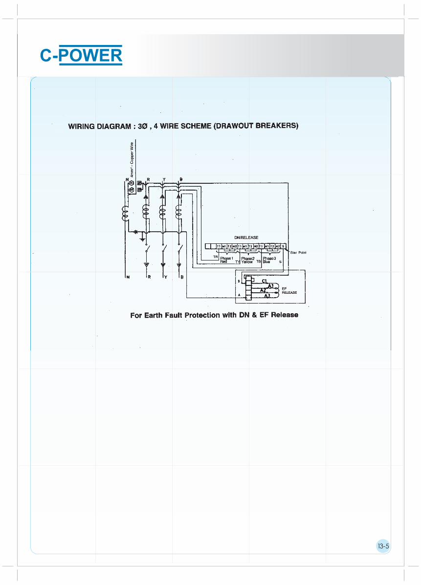
For Earth Fault Protection with SR21i / SR18G ReleaseNote: 1) Wining Diagram shown is for 3Pole ACBs. 2) For 4 Pole ACBs, Neutral CT may be mounted on Neutral Pole inside the Breaker and therefore Terminal No. 81 (& 82 for SR21i Release) may not be required in such cases.
A ±
1
B ± 1
13-5

TECHNICAL DATA
14-1
Rating (A)
Type Designation
0 Rated current (A) at 40 c
Rated operational voltage (V), 50/60Hz
Rated insulation voltage (V), 50/60Hz
No. of poles
Rated ultimate short circuit breaking
capacity 50/60Hz (kA rms)
Rated service short circuit breaking
capacity 50/60Hz (kA rms)
Rated short time
withstand capacity
50/60Hz (kA rms)
Rated making capacity
50/60Hz (kA peak)
Rated impulse withstand voltage
of main circuit (kV)
Rated impulse withstand voltage
of aux. circuit (kV)
Typical opening time (ms)
Typical closing time (ms)
Utilization category
Suitability for isolation
Fixed
Draw out
Manual
Electrical
Electrical & Mechanical life (operating cycles)
Electrical life without maintenance
400
E
400
415
1000
3
50
-
50
-
50
42
-
105
-
8
4
380/415/500V
660/690V
380/415/500V
660/690V
0.5 sec
1 sec
3 sec
380/415/500V
660/690V
40
60
B
15000
6000
Fixed
Draw out
Dimensions H
W
D
3 Pole
4 Ploe
H
W
D
3 Pole
4 Ploe
385
316
-
423.5
-
-
-
-
3
50
-
50
-
50
42
-
105
-
3/4
50
-
50
-
50
42
-
105
-
630
415
1000
E S1 E S1 C H
800
415
1000
630 800 1000
E S1 C H
1000
415
1000
3
50
-
50
-
50
42
-
105
-
3/4
50
35
50
35
50
50
35
105
73.5
50
-
50
-
50
42
-
105
-
65
50
65
50
65
65
50
143
105
3
50
-
50
-
50
42
-
105
-
3/4
50
35
50
35
50
50
35
105
73.5
50
-
50
-
50
42
-
105
-
65
50
65
50
65
65
50
143
105
8
4
12
4
8
4
12
4
12
4
12
4
8
4
12
4
12
4
12
4
40
60
B
40
60
B
40
60
B
40
60
B
40
60
B
40
60
B
40
60
B
40
60
B
40
60
B
40
60
B
15000
6000
15000
6000
15000
6000
6000
6000
8000
8000
20000
6000
8000
8000
20000
385
316
-
423.5
-
-
-
-
385
316
-
423.5
385
316
-
423.5
-
-
-
-
-
-
-
-
394
326
414
431
394
326
414
431
-
-
-
-
468
399
487
587
-
-
-
-
468
399
487
587
468
399
487
587
-
-
-
-
1
1
1
* Please consult us for applications at dc voltages & higher operational voltages upto 1000V ac.** Electrical life = Mechanical life, however arcing contacts need to be replaced depending upon wear. Arcing contacts are readily available as spares & easily replaceable at site.

TECHNICAL DATA
14-2
8
4
40
60
B
6000
385
316
-
423.5
-
-
-
-
3
50
-
50
-
50
42
-
105
-
E
1
1
1
65
50
65
50
65
65
50
143
105
50
35
50
35
50
50
35
105
73.5
H
12
4
12
4
40
60
B
40
60
B
20000
7000
7000
394
326
414
431
468
399
487
587
1250
1250
415
1000
E
3
50
-
50
-
50
42
-
105
-
8
4
40
60
B
6000
385
316
-
423.5
-
-
-
-
3
50
-
50
-
50
42
-
105
-
C H H
1600
415
1000
E S1 C
2000
415
1000
65
50
65
50
65
65
50
143
105
50
35
50
35
50
50
35
105
73.5
50
-
50
-
50
42
-
105
-
3/4
55
40
55
40
55
55
50
121
84
75
65
75
65
75
75
65
165
143
12
4
12
4
8
4
12
4
12
4
12
4
40
60
B
40
60
B
40
60
B
40
60
B
40
60
B
40
60
B
4500
7000
4500
20000
5000
5000
20000
-
-
-
-
468
555
701
587
1600 2000
3/4
7000
394
326
414
431
468
399
487
587
385
316
-
423.5
-
-
-
-
468
399
487
587
394
482
628
431
C
60
40
60
40
60
60
55
132
84
12
4
40
60
B
5000
2500
H
2500
415
1000
3/4
75
65
75
65
75
75
65
165
143
12
4
40
60
B
5000
20000
468
555
701
587
394
482
628
431
3200 4000 5000 6300
H0 H1 H0 H C C
3200
415
1000
3/4
4000
415
1000
3/4
5000
415
1000
3/4
6300
415
1000
3/4
75
65
75
65
75
75
70
165
143
100
85
100
85
100
100
85
220
187
75
65
75
65
75
75
70
165
143
100
85
100
85
100
100
85
220
187
95
95
95
95
209
95
95
95
95
209
12
4
12
4
12
4
12
4
12
4
12
4
40
60
B
40
60
B
40
60
B
40
60
B
40
60
B
40
60
B
10000
5000
5000
468
701
909
587
10000
5000
5000
468
701
909
587
5000
2500
583
913
1182
691
-
-
-
-
-
-
-
-
5000
2500
583
913
1182
691
3/4
CS1
12
4
40
60
B
6000
-
-
-
-
50
-
50
-
50
42
-
105
-
S1
12
4
40
60
B
6000
-
-
-
-
50
-
50
-
50
42
-
105
-
S1
12
4
40
60
B
4500
-
-
-
-
60
-
60
-
60
55
-
132
-
S1
12
4
40
60
B
4500
-
-
-
-
60
-
60
-
60
60
-
132
-
468
555
701
587

1
1
1
SPECIAL APPLICATIONS
15-1
11.1. 690V Application of C-POWER ACBs11.1 1.C-Power breakers are also suitable for operation at 690V with following changes / precautions.
a) Arc chute suitable for 690V to be usedb) Characteristics such as rated service Short circuit breaking capacity and rated ultimate short circuit breaking capacity are as specified on label.c) Only top terminals (marked line) of breaker are to be connected to the incoming side of supply.
11.1.1.1 The label indicating suitability of the breaker at 690V with special arc chutes is put on the facia of the breaker.
The label indicating characteristics is put just below the nameplate on the side of the breaker.
The label identifying ‘Line’ terminal is put above the top terminal on the rear side of the breaker in fixed ACBs and on the rear side of the cradle in draw out ACBs.