Repair Manual - Mammoet Industries · 02/02 AWB0207+9119-1406 GB-5 English 3 Mechanical Design...
28
Transcript of Repair Manual - Mammoet Industries · 02/02 AWB0207+9119-1406 GB-5 English 3 Mechanical Design...

02/02 AWB0207+9119-1406
Engl
ish
Explosion-Proof F&G Three-Phase Motors

Before commencing repair work
The following safety instructions for the repair of explosion-proof three-phase motors in flameproof enclosures – designation: Ex II 2.EEx d(e) IIC(B) T – must be observed in addition to the general installation instructions and the provisions of the operating manual. The operating manual provides instructions on the installation of the standard motor types and is not a substitute for any specialist training in the sense of the relevant explosion protection standards.
• Disconnect the power supply of the device
• Ensure that the device cannot be accidentally restarted
• Verify isolation from the supply
• Earth and short-circuit
• Cover or enclose neighbouring units that are live.
• Follow the installation instructions of the device concerned.
• Only suitably qualified personnel in accordance with EN 50110-1/-2 (VDE 0105 Part 100) may work on this device/system.
• The electrical installation must be carried out in accordance with the relevant regulations (e.g. for cable cross-sections, fuses, protective conductor connections).
• The opening of the motor without the manufacturer's consent, apart from the opening of terminal boxes, will invalidate the warranty during the warranty period.
• Original spare parts must be used for approved repairs or repairs outside of the warranty period.
• Electrically conducting and rotating parts of electric machines may cause serious and/or fatal injury.
• All transport, installation, commissioning and maintenance activities must only be carried out by qualified personnel. Observe the relevant standards for explosion protection such as EN 60079-14 and EN 50281-1-2, as well as national work safety regulations.
• Where installations are subject to these guidelines, appropriate safety measures must be taken in order to protect personnel from injury.
• Personnel must be instructed in how to proceed with care and observe the regulations in the transport, lifting and installation of the motor, as well as in recommissioning and repair.
• Do not use the lifting eye bolts to lift the motor together with the drive device.
• Do not use the supplied lifting eye bolts at ambient temperatures below –20 °C, in accordance with DIN 580. Lower temperatures could lead to the ring screws breaking and consequent injury to personnel and/or damage to the installation.
• The eye bolts should also not be loaded at an angle of more than 45 ° from the vertical direction and outside the plane of the ring, in accordance with DIN 580. In this case use transverse rods. Dimensions for positioning lifting eyes and minimum dimensions of transverse rods and chain lengths, see our operating manual.
• Suitable safety measures should be taken against possible brake failure on motors fitted with an external brake. This particularly applies to brake motors used in lifting applications.
• Avoid contact with the start and operation capacitors in single-phase motors until a secure discharge has occurred.
• If high-voltage tests are required, follow the procedures and precautionary measures laid down in the accident prevention regulations.
Moe
llerA
ntrie
bste
chni
kG
mbH
Safe
ty In
stru
ctio
ns
Warning!Dangerous electrical voltage!Observe explosion protection measures!
02/02 AWB0207+9119-1406
GB-1
Engl
ish
About This Manual GB-2Abbreviations and symbols GB-2
1 Explosion Protection GB-3Working on explosion-proof components GB-3– Joint connections and shaft bushings GB-3– Fastening screws GB-3– Seals, cable glands, entries and terminal points GB-3– After repair work GB-3
2 Maintenance Instructions GB-4
3 Mechanical Design GB-5Spare parts GB-6
4 Disassembly GB-7Ventilation system GB-7Integrated brake and rectifier, frame size 80 to 132 GB-8Integrated tacho-generator, frame size 80 to 132 GB-8End shields, rotors and roller bearings GB-8– Frame size 56 to 225 GB-8– From frame size 250 GB-10Terminal box GB-11– Removing the terminal box GB-11– Flameproof core bushing GB-12Forcing out stator cores, frame size 63 to 132 GB-13
5 Assembly GB-14Screw connections GB-14Frame size 80 to 132 GB-14– Motors with integral brake GB-14– Motors with an integral tacho-generator GB-14Flameproof cable glands, bushing plate GB-16– Frame size 63 to 160 GB-16– From frame size 180 GB-16Terminal box GB-17– Fitting the terminal box using a thread GB-17– Fitting the terminal box using screws GB-17– Connection diagrams GB-18End shields, rotors and roller bearings GB-20– Frame size 63 to 160 GB-20– Frame size 180 to 225 GB-21– From frame size 250 GB-22Brake GB-22Tacho-generator GB-23Ventilation system GB-23
6 Tests GB-24
Contents

02/02 AWB0207+9119-1406
GB-2
About This Manual
This manual describes the disassembly and assembly of CD.../BD... and dCD.../dBD... explosion-proof motors.
Abbreviations and symbols
This manual uses the following abbreviations and symbols:
DE: Drive endFS: Frame sizeNDE: Non-drive end
X Indicates instructions on what to do
Except for the first page of chapters and empty pages at the end, the top left of the page shows the chapter title and the top right of the page shows the current section for greater clarity.
h Draws your attention to useful tips and additional information
Important!Indicates the possibility of minor material damage.
Caution!Indicates the possibility of major damage to property or slight injury.
Warning!Indicates the possibility of major damage to property or serious or fatal injury.
02/02 AWB0207+9119-1406
B-3
Engl
ish
G
1 Explosion Protection
Parts on which explosion protection depends are:
• Gap connections and shaft bushings,• Fastening screws,• Seals,• Cable glands and entries,• Terminal points.
Working on explosion-proof components
Joint connections and shaft bushings
Corrosion protection can be achieved using non-curing sealant (static gap surfaces) or sealant grease (static or rotating gap surfaces). Permissible sealing materials are Hylomar from Marston-Domsel, or Admosit and Fluid-D from Teroson.
Fastening screws
Damaged screws must be replaced by new parts with the same material quality and must be sufficient for the number of fastening holes provided.
Seals, cable glands, entries and terminal points
Damaged parts must be replaced by original parts.
After repair work
If a part of a motor has been repaired on which explosion protec-tion depends, the following requirements must be fulfilled for commissioning:
An appointed inspector must verify that the essential explosion protection features of the motor meet the requirements of the applicable regulations. This inspector must issue the operator of the motor with appropriate certification of this compliance. The inspector must attach an appropriate approval mark on the motor or by issuing a test report.
Prior to recommissioning carry out the tests specified in Chapter “Tests”, Page 24.
Warning!The repair and recommissioning of explosion-proof motors in flameproof enclosures must comply with the relevant legal provisions:
These are the Directive 94/9/EEC; this has been imple-mented in Germany by the draft for electrical equipment in hazardous areas Elex V, DIN EN 50014, 50018 and 50019 and VDE 0170/0171 etc.
This particularly applies when work is carried out on parts on which explosion protection depends.
Caution!Gap surfaces (joint surfaces of components) must not be machined, coated or painted. Keep the surface metal clean. Surfaces must not have any surface damage (e.g. fractures or grooves).
Warning!All components used on the motor must comply with the protection type of the motor concerned and the relevant standards. This is denoted by designations such as II 2 G EEx d IIC(B) T4, on motor and components.
02/02 AWB0207+9119-1406
GB-4
2 Maintenance Instructions
The following components form a flameproof enclosure depending on axle height:
• Housing,• End shield,• Bearing cover,• Bushing plate with core or cable gland,• Shaft sections in the vicinity of shaft bushings in the
– Housing,– End shield or, – Bearing cover.
If these parts are damaged, such as due to fractures or grooves in the flameproof gaps (joints of individual components) they must be replaced with original parts. In accordance with EN 50018 gap surfaces must have a maximum average peak-to-valley height of Ra = 6.3 µm (ISO 468). Only original spare parts must be used.
If unmachined blanks are supplied and are finished by users them-selves according to original drawings, these parts must be subject to parts tests in accordance with EN 50018.
Always renew shaft seals and roller bearings every time the motor is disassembled. The roller bearings must be covered at both ends, depending on type, and filled with anti-friction roller bearing grease for lifetime lubrication or must be open.
Replace damaged screws with screws of the same strength. These must be sufficient for the number of fastening holes provided.
Check the stator winding and dry or repair it if necessary. To do this refer to the enclosed instructions for assembly, commissioning and maintenance of three-phase squirrel-cage motors housed in a flameproof enclosure and in a Chapter “Tests”, Page 24 of these instructions.

02/02 AWB0207+9119-1406
B-5
Engl
ish
G
3 Mechanical Design
Legend for Figure 1 and 2:
a Screw to DIN 912b Retaining ring to DIN 417c Featherkey to DIN 6885d Screw to DIN EN 24017e Screw to DIN 7964
f Retaining ring to DIN 472g Set screw to DIN 914h Cup spring or compensating platei Only with brake motors and motors with an integral tacho-generator
Figure 1: Explosion drawing for frame size 63 to 132
Figure 2: Explosion drawing for frame size 160 upwards
1.101.08
1.03
4.01
6.01
6.02
6.08
6.09 3.02 3.03 2.09 2.06
3.05
8.10
9.109.01 8.11
8.308.209.20
8.409.40
5.01 5.02a
ag
a d
a
c c
bbh b
i
b f
a
c
a
e
d
c
ah
a
a b d
d
b
ba
6.02 6.15
3.03 2.022.10 2.06
5.03
6.09-6.10
6.16-6.17
1.08
1.11
1.10
1.07
6.13
6.01
6.14 6.05
2.05 2.09 2.01 5.01
3.02
3.05
6.11
4.011.01
1.05 1.02
6.08
6.18
Mechanical Design 02/02 AWB0207+9119-1406
GB-6
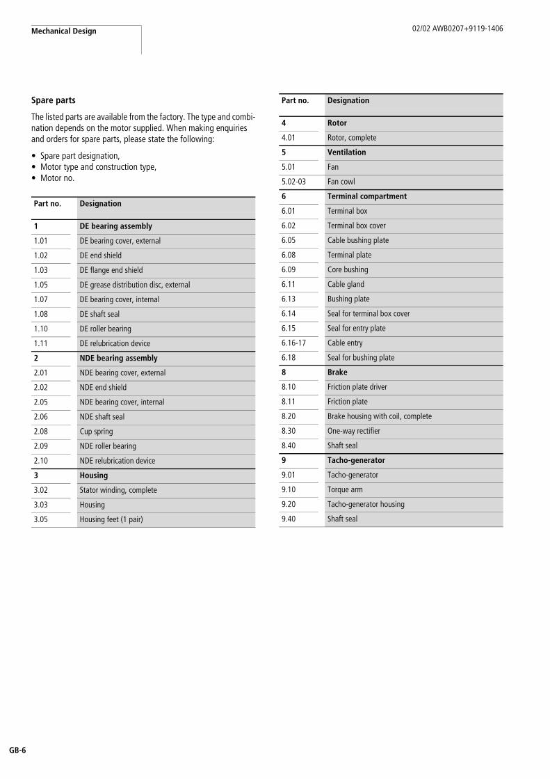
Spare parts
The listed parts are available from the factory. The type and combi-nation depends on the motor supplied. When making enquiries and orders for spare parts, please state the following:
• Spare part designation,• Motor type and construction type,• Motor no.
Part no. Designation
1 DE bearing assembly
1.01 DE bearing cover, external
1.02 DE end shield
1.03 DE flange end shield
1.05 DE grease distribution disc, external
1.07 DE bearing cover, internal
1.08 DE shaft seal
1.10 DE roller bearing
1.11 DE relubrication device
2 NDE bearing assembly
2.01 NDE bearing cover, external
2.02 NDE end shield
2.05 NDE bearing cover, internal
2.06 NDE shaft seal
2.08 Cup spring
2.09 NDE roller bearing
2.10 NDE relubrication device
3 Housing
3.02 Stator winding, complete
3.03 Housing
3.05 Housing feet (1 pair)
4 Rotor
4.01 Rotor, complete
5 Ventilation
5.01 Fan
5.02-03 Fan cowl
6 Terminal compartment
6.01 Terminal box
6.02 Terminal box cover
6.05 Cable bushing plate
6.08 Terminal plate
6.09 Core bushing
6.11 Cable gland
6.13 Bushing plate
6.14 Seal for terminal box cover
6.15 Seal for entry plate
6.16-17 Cable entry
6.18 Seal for bushing plate
8 Brake
8.10 Friction plate driver
8.11 Friction plate
8.20 Brake housing with coil, complete
8.30 One-way rectifier
8.40 Shaft seal
9 Tacho-generator
9.01 Tacho-generator
9.10 Torque arm
9.20 Tacho-generator housing
9.40 Shaft seal
Part no. Designation
02/02 AWB0207+9119-1406
B-7
Engl
ish
G
4 Disassembly
Ventilation system
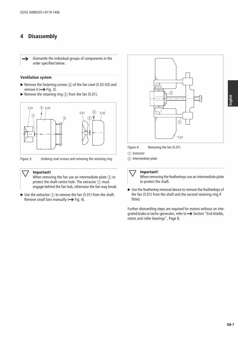
X Remove the fastening screws d of the fan cowl (5.02-03) and remove it (a Fig. 3).
X Remove the retaining ring b from the fan (5.01).
X Use the extractor a to remove the fan (5.01) from the shaft. Remove small fans manually (a Fig. 4).
X Use the featherkey removal device to remove the featherkeys of the fan (5.01) from the shaft and the second retaining ring if fitted.
Further dismantling steps are required for motors without an inte-grated brake or tacho-generator, refer to a Section “End shields, rotors and roller bearings”, Page 8.
h Dismantle the individual groups of components in the order specified below.
Figure 3: Undoing cowl screws and removing the retaining ring
Important!When removing the fan use an intermediate plate b to protect the shaft centre hole. The extractor a must engage behind the fan hub, otherwise the fan may break.
5.01 5.03
b
d
d
5.01 5.02d
b
Figure 4: Removing the fan (5.01)
a Extractorb Intermediate plate
Important!When removing the featherkeys use an intermediate plate to protect the shaft.
5.01
a
b
Disassembly 02/02 AWB0207+9119-1406
GB-8
Integrated brake and rectifier, frame size 80 to 132
The following requirements must be fulfilled in order to dismantle the integrated brake and rectifier:The fan must have already been removed.
X Remove the fastening screws of the brake housing.X Force the brake housing (8.20) from the motor housing centre
the forcing-off thread in the fastening cams.
X Lift off the brake housing (8.20) and rectifier and place it next to the motor.
The required cable length is provided in the motor housing.
To change the rectifier:
X Sever the cable to the motor directly at the board.X Undo the cable to the brake coil at the terminal strip.
The additional wires moulded into the brake are for temperature monitoring and must be severed at the crimp connections or the terminal strip (depending on type) when the brake housing is exchanged.
X Remove the friction plate from the friction plate driver (8.10).X Remove the retaining ring positioned in front of the friction
plate driver.X Remove the friction plate driver (8.10) with the extractor a
(a Fig. 6).
X Remove the featherkeys. With frame size 100, 112 and 132 remove the second retaining ring on the shaft.
Integrated tacho-generator, frame size 80 to 132
The following requirements must be fulfilled:The fan must have already been removed.
Follow the same dismantling procedure as for the brake.
To remove the tacho-generator (9.01) from the shaft undo the torque arm (9.10) and then carry out one of the following steps, depending on the type concerned:
X Remove the retaining ring in front of the tacho-generator (9.01) or
X Undo the terminal bolt on the hub of the tacho-generator.
The tachometer cable is drawn through the motor housing into the motor terminal compartment, so that the drive end must be opened before it can be withdrawn to exchange the tacho-gener-ator (9.01).
End shields, rotors and roller bearings
Frame size 56 to 225
Frame size 56 to 160The following requirements must be fulfilled before dismantling:The fan and brake must have already been removed.
The NDE shaft seal (2.06) and retaining ring are located in front of the NDE roller bearing (2.09).
X Remove the NDE shaft seal (2.06) and the retaining ring (not with frame sizes 56 to 71).
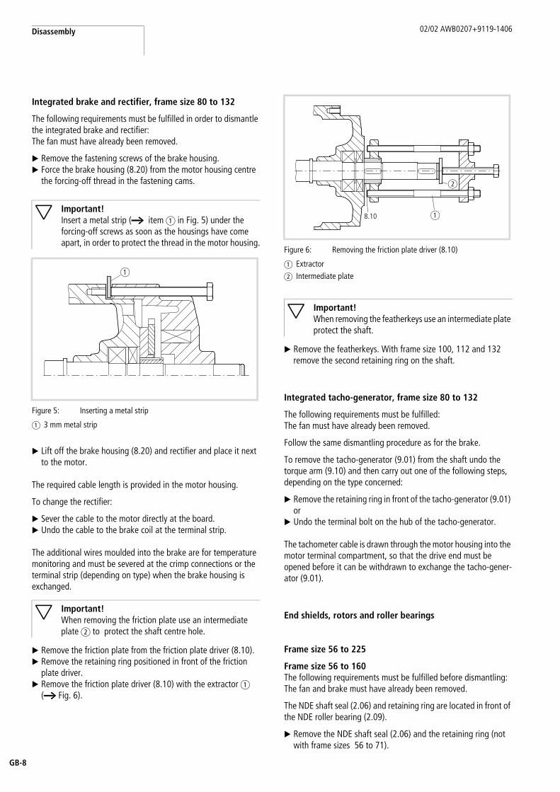
Important!Insert a metal strip (a item a in Fig. 5) under the forcing-off screws as soon as the housings have come apart, in order to protect the thread in the motor housing.
Figure 5: Inserting a metal strip
a 3 mm metal strip
Important!When removing the friction plate use an intermediate plate b to protect the shaft centre hole.
a
Figure 6: Removing the friction plate driver (8.10)
a Extractorb Intermediate plate
Important!When removing the featherkeys use an intermediate plate protect the shaft.
a
b
8.10
02/02 AWB0207+9119-1406 End shields, rotors and roller bearings
B-9
Engl
ish
G
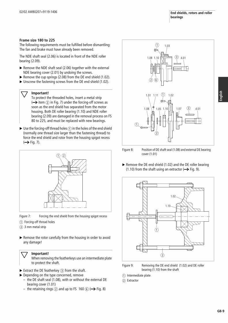
Frame size 180 to 225The following requirements must be fulfilled before dismantling:The fan and brake must have already been removed.
The NDE shaft seal (2.06) is located in front of the NDE roller bearing (2.09).
X Remove the NDE shaft seal (2.06) together with the external NDE bearing cover (2.01) by undoing the screws.
X Remove the cup springs (2.08) from the DE end shield (1.02).X Unscrew the fastening screws from the DE end shield (1.02).
X Use the forcing-off thread holes a in the holes of the end shield (normally one thread size larger than the fastening thread) to force the end shield and rotor from the housing spigot recess (a Fig. 7).
X Remove the rotor carefully from the housing in order to avoid any damage!
X Extract the DE featherkey c from the shaft.X Depending on the type concerned, remove
– the DE shaft seal (1.08), with or without the external DE bearing cover (1.01)
– the retaining rings b and up to FS 160 f (a Fig. 8)
X Remove the DE end shield (1.02) and the DE roller bearing (1.10) from the shaft using an extractor (a Fig. 9).
Important!To protect the threaded holes, insert a metal strip (a item b in Fig. 7) under the forcing-off screws as soon as the end shield has separated from the motor housing. Both DE roller bearing (1.10) and NDE roller bearing (2.09) are damaged in the removal process on FS 80 to 225, and must be replaced with new bearings.
Figure 7: Forcing the end shield from the housing spigot recess
a Forcing-off thread holesb 3 mm metal strip
Important!When removing the featherkeys use an intermediate plate to protect the shaft.
ba
Figure 8: Position of DE shaft seal (1.08) and external DE bearing cover (1.01)
Figure 9: Removing the DE end shield (1.02) and DE roller bearing (1.10) from the shaft
a Intermediate plateb Extractor
1.08 1.10
1.03
4.01c
a
b f
1.08 1.05
1.01 1.11
1.10 1.07
1.02
4.01
b
c
a
a
a
b
1.02
1.10
Disassembly 02/02 AWB0207+9119-1406
GB-10
X With FS 80 to 132 use a mandrel to knock the NDE roller bearing (2.09) out of the housing through the shaft bushing. With FS 160 to 225 use a mandrel to knock the NDE roller bearing (2.09) out of the NDE end shield (2.02). With FS 56 to 71 the DE roller bearing (2.09) must be removed from the shaft using an extractor.
This will damage the bearings which must therefore be replaced.
X Unscrew and remove the fastening screws (frame sizes 160 to 225) from the NDE end shield (2.02).
X Use the forcing-off thread holes in the end shield to force the NDE end shield (2.02) from the housing spigot recess (a Fig. 7).
From frame size 250
X Unscrew the fastening screws of the external DE (1.01) and NDE (2.01) bearing covers.
X Remove the DE shaft seal (1.08) in front of the DE roller bearing (1.10) to be removed together with DE (1.01) and NDE (2.01) external bearing covers.
X Remove cup springs, depending on type.X Unscrew and remove the fastening screws of the DE (1.02 or
1.03) and NDE (2.02) end shield.
Only bearing point for frame size 250, NDEX Use the forcing-off thread holes to force the NDE end shield
(2.02) together with the NDE roller bearings (2.09) from the housing spigot recess.
This will damage the NDE roller bearings which must be replaced.
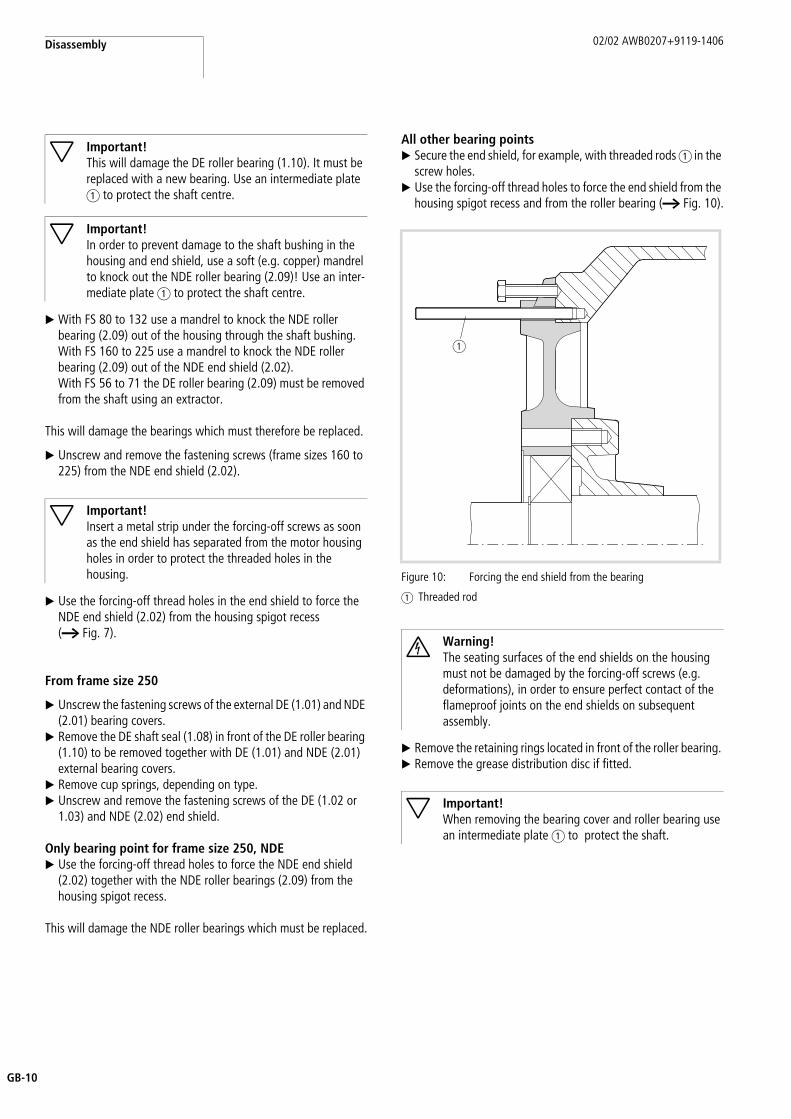
All other bearing pointsX Secure the end shield, for example, with threaded rods a in the
screw holes.X Use the forcing-off thread holes to force the end shield from the
housing spigot recess and from the roller bearing (a Fig. 10).
X Remove the retaining rings located in front of the roller bearing. X Remove the grease distribution disc if fitted.
Important!This will damage the DE roller bearing (1.10). It must be replaced with a new bearing. Use an intermediate plate a to protect the shaft centre.
Important!In order to prevent damage to the shaft bushing in the housing and end shield, use a soft (e.g. copper) mandrel to knock out the NDE roller bearing (2.09)! Use an inter-mediate plate a to protect the shaft centre.
Important!Insert a metal strip under the forcing-off screws as soon as the end shield has separated from the motor housing holes in order to protect the threaded holes in the housing. Figure 10: Forcing the end shield from the bearing
a Threaded rod
Warning!The seating surfaces of the end shields on the housing must not be damaged by the forcing-off screws (e.g. deformations), in order to ensure perfect contact of the flameproof joints on the end shields on subsequent assembly.
Important!When removing the bearing cover and roller bearing use an intermediate plate a to protect the shaft.
a
02/02 AWB0207+9119-1406 Terminal box
B-11
Engl
ish
G
X Remove the internal DE (1.07) or NDE (2.05) bearing cover together with the roller bearing from the shaft (a Fig. 11).
Terminal box
Removing the terminal box
X Remove the terminal box cover (6.02).
Frame size 63 to 112With terminal boxes fastened with four screws, proceed as described in Section “Frame sizes 132 and 160”, Page 11.
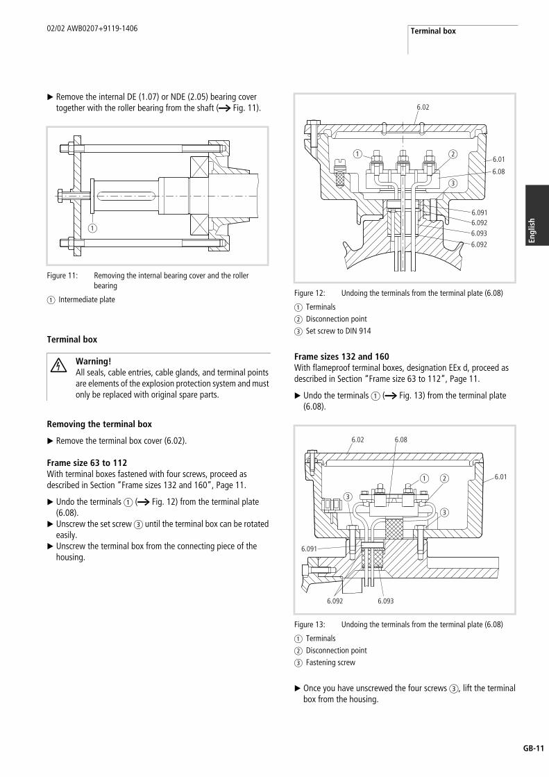
X Undo the terminals a (a Fig. 12) from the terminal plate (6.08).
X Unscrew the set screw c until the terminal box can be rotated easily.
X Unscrew the terminal box from the connecting piece of the housing.
Frame sizes 132 and 160With flameproof terminal boxes, designation EEx d, proceed as described in Section “Frame size 63 to 112”, Page 11.
X Undo the terminals a (a Fig. 13) from the terminal plate (6.08).
X Once you have unscrewed the four screws c, lift the terminal box from the housing.
Figure 11: Removing the internal bearing cover and the roller bearing
a Intermediate plate
Warning!All seals, cable entries, cable glands, and terminal points are elements of the explosion protection system and must only be replaced with original spare parts.
a
Figure 12: Undoing the terminals from the terminal plate (6.08)
a Terminalsb Disconnection pointc Set screw to DIN 914
Figure 13: Undoing the terminals from the terminal plate (6.08)
a Terminalsb Disconnection pointc Fastening screw
a b
c
6.02
6.01
6.08
6.0916.0926.093
6.092
a b
c
c
6.02 6.08
6.092
6.091
6.01
6.093

Disassembly 02/02 AWB0207+9119-1406
GB-12
From frame size 180X Undo the fastening screws a (a Fig. 14).X Remove the terminal box (6.01) from the bushing plate (6.13).X Using two forcing-off threads to force the bushing plate (6.13)
with the cable glands (6.09) from the housing spigot recess.
Flameproof core bushing
Frame size 63 to 160X Undo the terminals a (a Fig. 12, Page 11 and Fig. 13,
Page 11) on the terminal plate (6.08).X Sever the winding cables directly on the cable lug b.X Loosen the pressure ring (6.091).X Pull the winding cables through the pressure plates (6.092) and
the sealing ring (6.093) into the housing.X Remove the sealing ring and the pressure plates from the
housing.
The pressure ring is secured with adhesive. It can be removed by overcoming the locking torque.
From frame size 180Proceed as follows to disconnect the stator winding of motors with moulded core bushings (a Fig. 14):
X Disconnect the winding cables directly next to the crimp connections b.
If the winding cables are passed through the entries directly to the terminal plate, proceed as follows (a Fig. 15):
X Disconnect the winding cables directly on the cable lug.X Undo the gland for the core bushing (6.09).X Pull back the winding cables into the housing.
Motors with bolt-type glandsX Undo the retaining plate a and nut (a Fig. 16).X Disconnect the winding cables from the threaded bolts.
The glands or entries are secured with adhesive. They can be removed by overcoming the locking torque.
For the cores of the additional conductor, proceed as described in Section “Frame size 63 to 160”, Page 12.
Figure 14: Removing the terminal box from the bushing plate
a Fastening screwsb Disconnection point
Important!The seating surface of the bushing plate on the housing must not be damaged by the forcing-off threads (e.g. deformations), in order to ensure perfect contact of the flameproof joints on the bushing plate on subsequent assembly.
b
a6.01
6.05
6.16
6.09
6.13
Figure 15: Undoing the terminals from the terminal plate (6.08)
a Disconnection point
Figure 16: Terminal box with bolt-type gland
a Retaining plate
1
2
3
a6.01
6.09
6.13 6.16
6.051
2
3
a
6.01
6.13
6.17

02/02 AWB0207+9119-1406 Forcing out stator cores, frame size 63 to 132
B-13
Engl
ish
G
Forcing out stator cores, frame size 63 to 132
The motor must be dismantled completely, in order to force out the stator core.
X Push the removal device into the housing.X Rotate the spindle c. This will cause the arms b (a Fig. 17)
to spread.
Different expander elements are available for different core diameters.
X Place the device prepared in this way on a tube a with an internal diameter larger than the internal diameter of the housing.The surface of the tube must be clean and smooth so that the contact surfaces of the motor housing are not damaged.
X Press with the sleeve f through the non-drive end of the shaft bushing onto the expander element d in order to push the stator core out of the housing.
h A special removal device can be ordered from Moeller for forcing out a stator core from a pot-type housing.
Figure 17: Removal device for stator cores
a Tubeb Armsc Spindled Expander elemente Shouldersf Sleeve
a b c d e
f
Important!Ensure that the shoulders e of the arms b completely engage behind the stator core and that the arms them-selves are positioned correctly in the core. Pre-tighten the spindle c so that the device is secure and does not slide. This could otherwise damage the device.
Caution!Do not damage the shaft bushing. This may make the housing unsuitable for further use!

02/02 AWB0207+9119-1406
GB-14
5 Assembly
The following parts are those on which explosion protection depends:
• Screws,• Seals,• Cable entries and glands,• Terminal points.
Screw connections
Ensure that the screws are fitted without washers or other securing elements, and are sufficient for the number of fastening holes provided. The following tightening torques are required to prevent accidental loosening, unless otherwise specified:
Tabelle 1: Tightening torques for grade 8.8 screws
Tabelle 2: Tightening torques for conductive bolts
Frame size 80 to 132
Motors with integral brake
The following steps must be carried out as shown in Figure 18:
X Pass the connection cores c of the rectifer (8.30)– from the non-drive end– through a groove d in the housing– over the stator core b– through the hole of core bushing a to the drive end of the
housing.
Two cores are for temperature monitoring, the other four are used for the brake power supply.
With versions without a rectifier, only four cores are required, two for temperature monitoring and two for the brake.
The core connection is described in Section “Fitting the terminal box using screws”, Page 17.
Motors with an integral tacho-generator
The following steps must be carried out as shown in Figure 19, Page 15:
X Insert the rotor into the motor housing.X Push the NDE roller bearing (2.09) with the internal cup spring
(2.08) onto the shaft and into the housing at the same time. X Depending on type, secure the roller bearing with a retaining
ring.X Push the tacho-generator (9.01) onto the shaft.X Tighten the torque arm (9.10) of the tacho-generator (9.01) on
the housing. Do not, however, secure the tacho-generator axially on the shaft.
Caution!Only use original spares to replace parts on which explosion protection depends. Explosion protection will otherwise be lost.
Important!Protect all machined mounting surfaces against corrosion by greasing.
Screw size Tightening torqueNm
M5 6
M6 10
M8 25
M10 49
M12 85
M16 210
M20 425
Thread size Tightening torqueNm
M4 1.2
M5 2
M6 3
M8 6
M10 10
M12 15.5
M16 30
Figure 18: Cabling the rectifier (8.30)
a Core bushingb Stator corec Connection cores of the rectifierd Groove in the housing
8.30
a b d
c
02/02 AWB0207+9119-1406 Frame size 80 to 132
B-15
Engl
ish
G
Type with flameproof terminal boxesFlameproof terminal boxes, designation, EEx d IIB+H2 T., do not require a flameproof core bushing. The terminal box and the motor housing form one complete flameproof compartment.
X Pass the connection cable c of the tacho-generator (9.01)– from the non-drive end– through a groove d in the housing– over the stator core b– through the wire hole of the core bushing a to the terminal
box.
Save a loop of the cable between the tacho-generator and the housing so that the housing (9.20) of the tacho-generator can be mounted without damaging the cable.
Depending on the type, secure the cable on the motor housing with a clip (a Fig. 20).
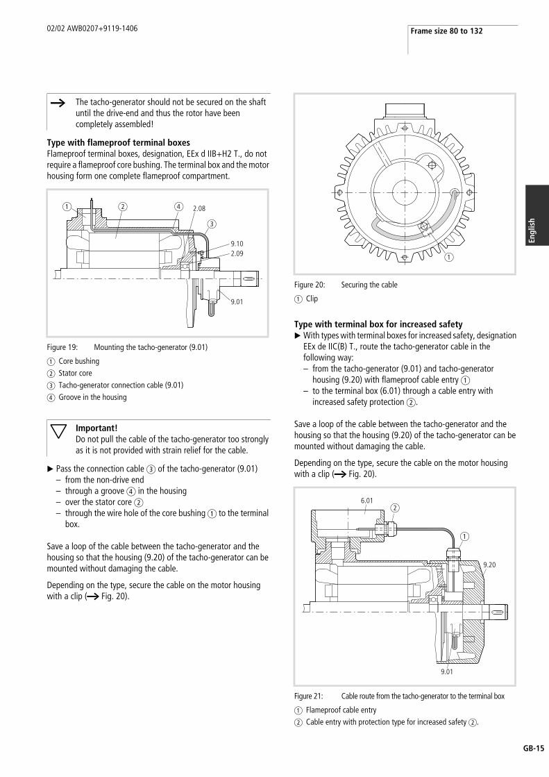
Type with terminal box for increased safetyX With types with terminal boxes for increased safety, designation
EEx de IIC(B) T., route the tacho-generator cable in the following way:– from the tacho-generator (9.01) and tacho-generator
housing (9.20) with flameproof cable entry a– to the terminal box (6.01) through a cable entry with
increased safety protection b.
Save a loop of the cable between the tacho-generator and the housing so that the housing (9.20) of the tacho-generator can be mounted without damaging the cable.
Depending on the type, secure the cable on the motor housing with a clip (a Fig. 20).
h The tacho-generator should not be secured on the shaft until the drive-end and thus the rotor have been completely assembled!
Figure 19: Mounting the tacho-generator (9.01)
a Core bushingb Stator corec Tacho-generator connection cable (9.01)d Groove in the housing
Important!Do not pull the cable of the tacho-generator too strongly as it is not provided with strain relief for the cable.
9.01
9.10
2.08
2.09
a b d
c
Figure 20: Securing the cable
a Clip
Figure 21: Cable route from the tacho-generator to the terminal box
a Flameproof cable entryb Cable entry with protection type for increased safety b.
a
6.01
9.01
9.20
a
b

Assembly 02/02 AWB0207+9119-1406
GB-16
Flameproof cable glands, bushing plate
Frame size 63 to 160
X Pass the stator winding leads and the additional cores through the sealing ring (6.093) located between two pressure plates (6.092) (a Fig. 22).
The upper pressure plate must have an anti-rotation feature if this is provided in the housing.
X Tighten the thrust ring (6.091) to at least 20 Nm.X Secure it with an anaerobic adhesive (observe manufacturer's
instructions).
Only wire supplied by Elumeg (type 155-U) can be used as winding cable, depending on the hole size in the sealing ring:
• Minimum external diameter 2.4 mm for 3 mm holes, • Minimum external diameter 3.1 mm for 4 mm holes.
X Seal unused holes with Cu rivets 3 x 25 and 4 x 25 to DIN 660.
The rivet head must lie under the upper pressure plate (6.092) (a Fig. 22).
From frame size 180
X Screw the moulded core bushings and bolt-type glands (6.09) (a Fig. 14 and Fig. 16) from the motor end into the bushing plate (6.13) and secure with anaerobic adhesive (observe manufacturers' instructions).
X Screw in rubber sealing cable entries (6.09, Fig. 15) from the terminal box side and secure with anaerobic adhesive.
X Connect the winding cables to the cables of the moulded core bushing using crimp connections.
X Insulate this using class F heat shrinkable tubing.X Connect the winding cables to the bolt-type glands by using
crimp cable lugs.X Use a retaining plate a (a Fig. 23) to prevent the fastening
nut from working loose.
When using rubber sealed entries:
X Pass the winding cables with crimp cable lugs directly to the terminal plate (6.08) (a Section “Terminal box”, Page 11).
For the cores of the additional conductors, proceed as described in Section “Frame size 63 to 160”, Page 12.
After fitting the bushings and connecting them to the winding cables:
X Insert the bushing plate (6.13) into the connecting piece of the housing.
X Depending on type, secure the bushing plate (6.13) on its own or together with the terminal box (6.01) in the housing.
h The correct mounting of the core bushing must be checked by an appointed specialist.
Figure 22: Passing the stator winding lead to terminal box
a Cu rivet to DIN 660
6.016.091
6.092
6.092
6.093
a
Figure 23: Securing the fastening nut
a Retaining plate
a
1

02/02 AWB0207+9119-1406 Terminal box
B-17
Engl
ish
G
Terminal box
Fitting the terminal box using a thread
Proceed as follows in order to fit the terminal box via a thread (a Fig. 24):
X Screw in the terminal box up to the stop of the thread on the connecting piece of the housing.
X Now rotate the terminal box back up to one turn to the required location of the entries.
X Tighten the set screws a for securing.X Secure this with a contact anaerobic adhesive (observe manu-
facturer's instructions).
Fitting the terminal box using screws
Proceed as follows in order to fit the terminal box (6.01) using screws (a Fig. 25):
X Place the terminal box (6.01) with a rubber seal (only use orig-inal seal) on the housing and the bushing plate (6.13).
X Fasten the terminal box with screws
Proceed as follows with terminal boxes with a terminal plate:X Screw the terminal plate (6.08) with two cylinder head screws.X Crimp the terminal plate cable lugs onto the ends of the
winding cables.X Fasten the cable lugs using nuts and spring washers on the
terminal plate, together with:– terminal clamp and terminal parts,– connection rails.
Remaining procedure for all terminal boxes:X Fasten the measuring and control cables in the mini-terminals.X Screw the mini-terminals with the appropriate special screw.X Request a circuit diagram (a Section “Connection diagrams”,
Page 18) if none are available!
Tabelle 3: Cable markings
X Place the terminal box cover (6.02) on the terminal box (6.01) and fasten it with screws.
With terminal boxes for increased safety, designation EEx e ensure the correct seating of the seal, if necessary secure in the cover with contact adhesive.
Proceed as follows with terminal box covers fastened via a thread:
X Screw in the cover up to the stop of the thread of the box.X Depending on type, rotate the cover a maximum of k turns up
to the next stop and secure immediately with the set screw.
Figure 24: Fastening the terminal box (6.01) via a thread
a Set screw to DIN 914
Figure 25: Fitting the terminal box using screws
a
6.01
3.03
6.08
6.01
6.05
6.166.096.13
6.08
6.01
6.056.08
6.166.13 3.03
6.01
6.13
U1 red
U2 white and red
V1 black
V2 white and black
W1 blue
W2 white and blue
1 to 4 Brake
5 and 6 Tacho-generator
10 to 13 PTC thermistor temperature sensor
20 to 23 Resistance temperature sensor
70 and 71 Heater
Assembly 02/02 AWB0207+9119-1406
GB-18
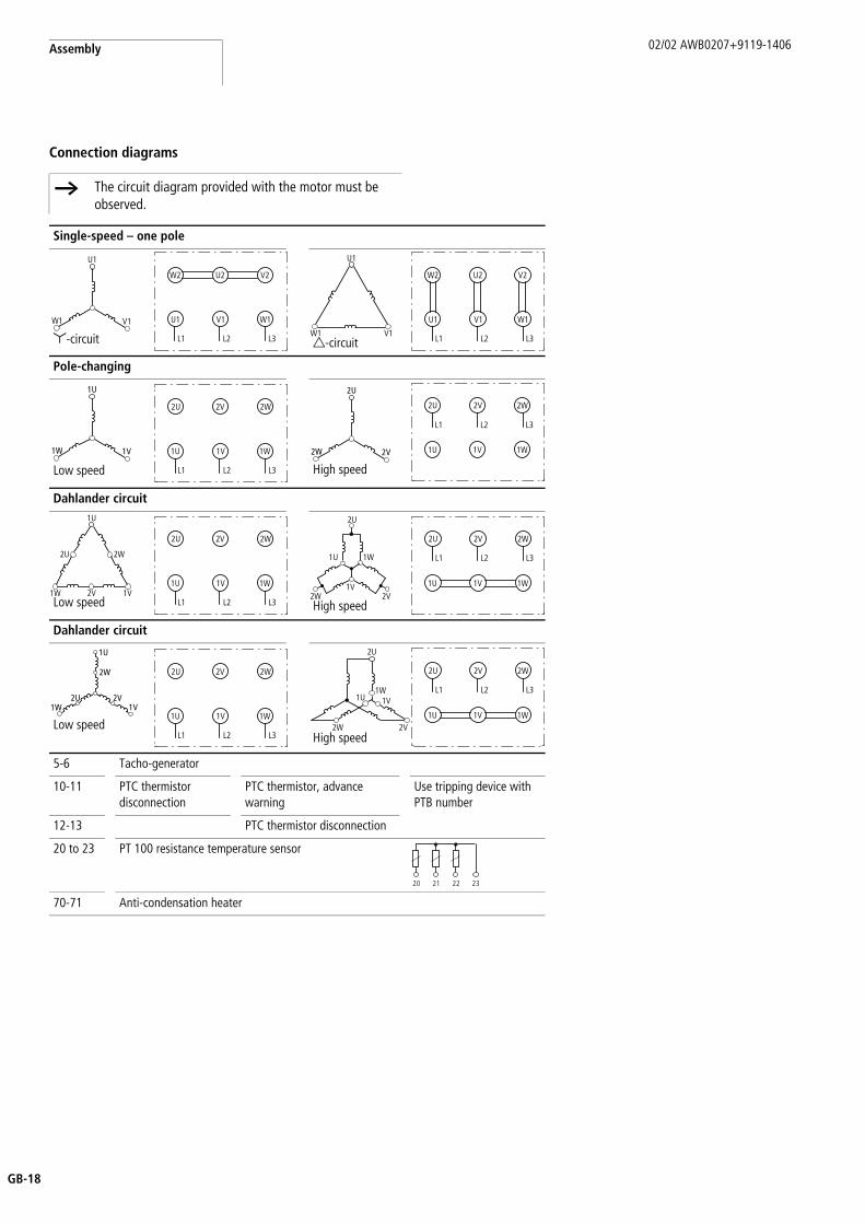
Connection diagrams
h The circuit diagram provided with the motor must be observed.
Single-speed – one pole
y-circuit d-circuit
Pole-changing
Low speed High speed
Dahlander circuit
Low speed High speed
Dahlander circuit
Low speedHigh speed
5-6 Tacho-generator
10-11 PTC thermistor disconnection
PTC thermistor, advance warning
Use tripping device with PTB number
12-13 PTC thermistor disconnection
20 to 23 PT 100 resistance temperature sensor
70-71 Anti-condensation heater
W1 V1
U1
W2 U2 V2
U1 V1 W1
L3L2L1W1 V1
U1
W2 U2 V2
U1 V1 W1
L3L2L1
1W 1V
1U
2U 2V 2W
1U 1V 1W
L3L2L1
2W 2V
2U
2U 2V 2W
1U 1V 1W
L3L2L1
1W 1V2V
1U
2U 2W
2U 2V 2W
1U 1V 1W
L3L2L1
1V
2U
1U 1W
2W 2V
2U 2V 2W
1U 1V 1W
L3L2L1
1U
1W 1V
2W
2V2U
2U 2V 2W
1U 1V 1W
L3L2L12W 2V
1U 1V1W
2U
2U 2V 2W
1U 1V 1W
L3L2L1
20 21 22 23
02/02 AWB0207+9119-1406 Terminal box
B-19
Engl
ish
G
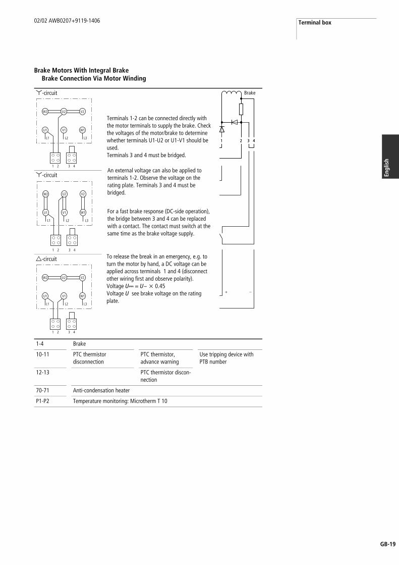
Brake Motors With Integral BrakeBrake Connection Via Motor Winding
y-circuit
y-circuit
d-circuit
1-4 Brake
10-11 PTC thermistor disconnection
PTC thermistor, advance warning
Use tripping device with PTB number
12-13 PTC thermistor discon-nection
70-71 Anti-condensation heater
P1-P2 Temperature monitoring: Microtherm T 10
W2 U2 V2
U1 V1 W1
L3L2L1
1 2 3 4
For a fast brake response (DC-side operation), the bridge between 3 and 4 can be replaced with a contact. The contact must switch at the same time as the brake voltage supply.
An external voltage can also be applied to terminals 1-2. Observe the voltage on the rating plate. Terminals 3 and 4 must be bridged.
Terminals 1-2 can be connected directly with the motor terminals to supply the brake. Check the voltages of the motor/brake to determine whether terminals U1-U2 or U1-V1 should be used.Terminals 3 and 4 must be bridged.
To release the break in an emergency, e.g. to turn the motor by hand, a DC voltage can be applied across terminals 1 and 4 (disconnect other wiring first and observe polarity).Voltage UH = U~ x 0.45Voltage U see brake voltage on the rating plate.
1 2 3 41 2 3
+ _
4
Brake
W2 U2 V2
U1 V1 W1
L3L2L1
1 2 3 4
W2 U2 V2
U1 V1 W1
L3L2L1
1 2 3 4
Assembly 02/02 AWB0207+9119-1406
GB-20
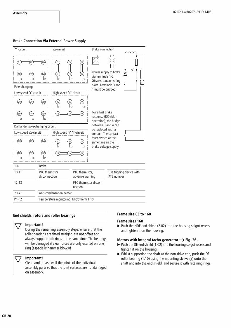
Brake Connection Via External Power Supply
End shields, rotors and roller bearings Frame size 63 to 160
Frame sizes 160X Push the NDE end shield (2.02) into the housing spigot recess
and tighten it on the housing.
Motors with integral tacho-generator a Fig. 26.X Push the DE end shield (1.02) into the housing spigot recess and
tighten it on the housing.X Whilst supporting the shaft at the non-drive end, push the DE
roller bearing (1.10) using the mounting sleeve a onto the shaft and into the end shield, and secure it with retaining rings.
y-circuit d-circuit Brake connection
Power supply to brake via terminals 1-2. Observe data on rating plate. Terminals 3 and 4 must be bridged.
Pole-changing
Low speed y-circuit High speed y-circuit
For a fast brake response (DC-side operation), the bridge between 3 and 4 can be replaced with a contact. The contact must switch at the same time as the brake voltage supply.
Dahlander pole-changing circuit
Low speed d-circuit High speed yy-circuit
1-4 Brake
10-11 PTC thermistor disconnection
PTC thermistor, advance warning
Use tripping device with PTB number
12-13 PTC thermistor discon-nection
70-71 Anti-condensation heater
P1-P2 Temperature monitoring: Microtherm T 10
2U 2V 2W
1U 1V 1W
L3L2L1
2U 2V 2W
1U 1V 1W
L3L2L1 1 2 3 41 2 3 4
1 2 3 4
2U 2V 2W
1U 1V 1W
L3L2L1
2U 2V 2W
1U 1V 1W
L3L2L1
2U 2V 2W
1U 1V 1W
L3L2L1
2U 2V 2W
1U 1V 1W
L3L2L1
Important!During the remaining assembly steps, ensure that the roller bearings are fitted straight, are not offset and always support both rings at the same time. The bearings will be damaged if axial forces are only exerted on one ring (especially hammer blows)!
Important!Clean and grease well the joints of the individual assembly parts so that the joint surfaces are not damaged on assembly.
02/02 AWB0207+9119-1406 End shields, rotors and roller bearings
B-21
Engl
ish
G
All other types (a Fig. 27)(not applicable to types with integral tacho-generator)
X Push the DE roller bearing (1.10) into the DE end shield (1.02).X Push the DE end shield with the DE roller bearing onto the rotor.
X Push the whole unit into the housing and fasten the end shield with screws.
X Insert a cup spring at the non-drive end in the bearing seat of the housing.
X Fit the DE roller bearing (1.10) whilst supporting the shaft at the drive end.
X Depending on type, secure the DE roller bearing, with a retaining ring in the shaft and in the housing.
X Depending on type, secure the NDE roller bearing, with a retaining ring in the shaft.
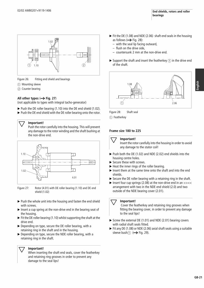
X Fit the DE (1.08) and NDE (2.06) shaft end seals in the housing as follows (a Fig. 28):– with the seal lip facing outward,– flush on the drive side,– countersunk 2 mm at the non-drive end.
X Support the shaft and insert the featherkey a in the drive end of the shaft.
Frame size 180 to 225
X Push both the DE (1.02) and NDE (2.02) end shields into the housing centre holes.
X Secure these with screws.X Heat the inner rings of the roller bearing.X Insert them at the same time onto the shaft and into the end
shields.X Secure the DE roller bearing with a retaining ring in the shaft.X Insert four cup springs (2.08) at the non-drive end in an >><<
arrangement with two in the NDE end shield (2.0) and two outside of the NDE bearing cover (2.01).
X Screw the external DE (1.01) and NDE (2.01) bearing covers with radial shaft seals fitted.
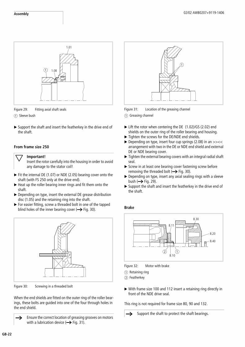
X Fit any DE (1.08) or NDE (2.06) axial shaft seals using a suitable sleeve busha (a Fig. 29).
Figure 26: Fitting end shield and bearings
a Mounting sleeveb Counter bearing
Important!Push the rotor carefully into the housing. This will prevent any damage to the rotor winding and the shaft bushing at the non-drive end.
Figure 27: Rotor (4.01) with DE roller bearing (1.10) and DE end shield (1.02)
Important!When inserting the shaft end seals, cover the featherkey and retaining ring grooves in order to prevent any damage to the seal lips!
1.02
1.10a b
1.10
1.02
4.01
Figure 28: Shaft seal
a Featherkey
Important!Insert the rotor carefully into the housing in order to avoid any damage to the stator coil!
Important! Cover the featherkey and retaining ring grooves when fitting the bearing cover, in order to prevent any damage to the seal lips!
a
1.08
2.06
Assembly 02/02 AWB0207+9119-1406
GB-22
X Support the shaft and insert the featherkey in the drive end of the shaft.
From frame size 250
X Fit the internal DE (1.07) or NDE (2.05) bearing cover onto the shaft (with FS 250 only at the drive end).
X Heat up the roller bearing inner rings and fit them onto the shaft.
X Depending on type, insert the external DE grease distribution disc (1.05) and the retaining ring into the shaft.
X For easier fitting, screw a threaded bolt in one of the tapped blind holes of the inner bearing cover (a Fig. 30).
When the end shields are fitted on the outer ring of the roller bear-ings, these bolts are guided into one of the four through holes in the end shield.
X Lift the rotor when centering the DE (1.02)/GS (2.02) end shields on the outer ring of the roller bearing and housing.
X Tighten the screws for the DE/NDE end shields.X Depending on type, insert four cup springs (2.08) in an >><<
arrangement with two in the DE or NDE end shield and external DE or NDE bearing cover.
X Tighten the external bearing covers with an integral radial shaft seal.
X Screw in at least one bearing cover fastening screw before removing the threaded bolt (a Fig. 30).
X Depending on type, insert any axial sealing rings with a sleeve bush (a Fig. 29).
X Support the shaft and insert the featherkey in the drive end of the shaft.
Brake
X With frame size 100 and 112 insert a retaining ring directly in front of the NDE drive seal.
This ring is not required for frame size 80, 90 and 132.
Figure 29: Fitting axial shaft seals
a Sleeve bush
Important!Insert the rotor carefully into the housing in order to avoid any damage to the stator coil!
Figure 30: Screwing in a threaded bolt
h Ensure the correct location of greasing grooves on motors with a lubrication device (a Fig. 31).
1.01
1.08a
Figure 31: Location of the greasing channel
a Greasing channel
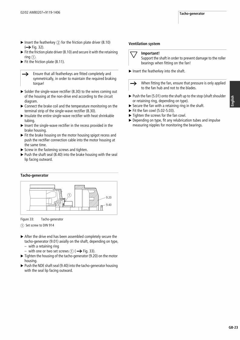
Figure 32: Motor with brake
a Retaining ringb Featherkey
h Support the shaft to protect the shaft bearings.
a
8.11
8.10
8.30
8.40
8.20
ab
02/02 AWB0207+9119-1406 Tacho-generator
B-23
Engl
ish
G
X Insert the featherkey b for the friction plate driver (8.10) (a Fig. 32).
X Fit the friction plate driver (8.10) and secure it with the retaining ring a.
X Fit the friction plate (8.11).
X Solder the single-wave rectifier (8.30) to the wires coming out of the housing at the non-drive end according to the circuit diagram.
X Connect the brake coil and the temperature monitoring on the terminal strip of the single-wave rectifier (8.30).
X Insulate the entire single-wave rectifier with heat shrinkable tubing.
X Insert the single-wave rectifier in the recess provided in the brake housing.
X Fit the brake housing on the motor housing spigot recess and push the rectifier connection cable into the motor housing at the same time.
X Screw in the fastening screws and tighten.X Push the shaft seal (8.40) into the brake housing with the seal
lip facing outward.
Tacho-generator
X After the drive end has been assembled completely secure the tacho-generator (9.01) axially on the shaft, depending on type,– with a retaining ring– with one or two set screws a ( a Fig. 33).
X Tighten the housing of the tacho-generator (9.20) on the motor housing.
X Push the NDE shaft seal (9.40) into the tacho-generator housing with the seal lip facing outward.
Ventilation system
X Insert the featherkey into the shaft.
X Push the fan (5.01) onto the shaft up to the stop (shaft shoulder or retaining ring, depending on type).
X Secure the fan with a retaining ring in the shaft.X Fit the fan cowl (5.02-5.03).X Tighten the screws for the fan cowl.X Depending on type, fit any relubrication tubes and impulse
measuring nipples for monitoring the bearings.
h Ensure that all featherkeys are fitted completely and symmetrically, in order to maintain the required braking torque!
Figure 33: Tacho-generator
a Set screw to DIN 914
9.40
9.20a
Important!Support the shaft in order to prevent damage to the roller bearings when fitting on the fan!
h When fitting the fan, ensure that pressure is only applied to the fan hub and not to the blades.
02/02 AWB0207+9119-1406
GB-24
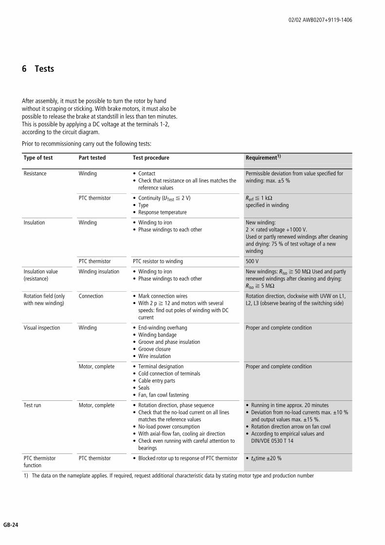
6 Tests
After assembly, it must be possible to turn the rotor by hand without it scraping or sticking. With brake motors, it must also be possible to release the brake at standstill in less than ten minutes. This is possible by applying a DC voltage at the terminals 1-2, according to the circuit diagram.
Prior to recommissioning carry out the following tests:
Type of test Part tested Test procedure Requirement1)
Resistance Winding • Contact• Check that resistance on all lines matches the
reference values
Permissible deviation from value specified for winding: max. g5 %
PTC thermistor • Continuity (UTest F 2 V)• Type• Response temperature
Rerf F 1 kOspecified in winding
Insulation Winding • Winding to iron• Phase windings to each other
New winding: 2 x rated voltage +1000 V.Used or partly renewed windings after cleaning and drying: 75 % of test voltage of a new winding
PTC thermistor PTC resistor to winding 500 V
Insulation value (resistance)
Winding insulation • Winding to iron• Phase windings to each other
New windings: Riso f 50 MO Used and partly renewed windings after cleaning and drying: Riso f 5 MO
Rotation field (only with new winding)
Connection • Mark connection wires• With 2 p f 12 and motors with several
speeds: find out poles of winding with DC current
Rotation direction, clockwise with UVW on L1, L2, L3 (observe bearing of the switching side)
Visual inspection Winding • End-winding overhang• Winding bandage• Groove and phase insulation• Groove closure• Wire insulation
Proper and complete condition
Motor, complete • Terminal designation• Cold connection of terminals• Cable entry parts• Seals• Fan, fan cowl fastening
Proper and complete condition
Test run Motor, complete • Rotation direction, phase sequence• Check that the no-load current on all lines
matches the reference values• No-load power consumption• With axial-flow fan, cooling air direction• Check even running with careful attention to
bearings
• Running in time approx. 20 minutes• Deviation from no-load currents max. g10 %
and output values max. g15 %.• Rotation direction arrow on fan cowl• According to empirical values and
DIN/VDE 0530 T 14
PTC thermistor function
PTC thermistor • Blocked rotor up to response of PTC thermistor • tAtime g20 %
1) The data on the nameplate applies. If required, request additional characteristic data by stating motor type and production number