Repair Maintenance
34
Pinnaccle Education Trust’s ELITTE INSTITUTE OF ENGINEERING MANAGEMENT (An ISO 9001:2008 Certified Polytechnic Institute) Approved by A.I.C.T.E. & Affiliated to W.B.S.C.T.E . Automobile Repair MAINTENANCE LAB EXPERIMENT NO. - AUTO/5 & 6/S2/ARMS- 1(a)&(b) 1. Title of the Experiment : -- a) Inspection of Crank Shaft, Assessment of workability and determination of undersize condition of journals. & b) Setting p rocedure of Crankshaft of Multi cylinder Engines in Crankshaft regrindin g machine for grinding both crank pin and mail Journals, Check for Eccentricity cranks. Theory: -- Grinding is a process of removing material by the abrasive action of a revolving wheel on the surface of a work piece, in order to bring it to the required shape and size. Crank shaft grinding is necessary for smoothness of main journal and crankpins. Object of the Job:-- To practice servicing adjustment and over of the crank shaft of the multi- cylinder engine. Tools and Equipment: -- 1. V Block. 2. Dial gauge. 3. Open ended spanner. 4. Ring spanner 5.Adjustable wrench. 6. Allen keys. 7. Socket spanner. 8. Crank shaft regrinding mixture. Trainee Material: -- Lubricating oil, fine M.I.R paper, cotton waste. Procedure: -- Ovality is determined by measuring diameter at 125º apart of place with a micrometer. Taper is determined by measuring in liner in the journal by micrometer. If the bonding is wit hin 0.08 mm then the crank sha ft to be bend a s required. From the measuring reading Ovality and tapperness is determined. If the wear of journal and crank pin is more than 0.04 mm then it would be machined to the next undersize bearing. Remarks: -- 1. Crankshaft crankpin and main journal standard size should be known . 2. Ovality and tapperness should be measured three or four times at different places . 3. Oil groove should not be measured 4. Micrometer should be checked after taking reading. 5. Proper range of micrometer should be spected. 6. Crank should be grinded according to engine and bearing size should be selected.
Transcript of Repair Maintenance
8/13/2019 Repair Maintenance
http://slidepdf.com/reader/full/repair-maintenance 1/34
Pinnaccle Education Trust’s ELITTE INSTITUTE OF ENGINEERING MANAGEMENT
(An ISO 9001:2008 Certified Polytechnic Institute)Approved by A.I.C.T.E. & Affiliated to W.B.S.C.T.E. Automobile Repair MAINTENANCE LAB
EXPERIMENT NO. - AUTO/5 & 6/S2/ARMS- 1(a)&(b)
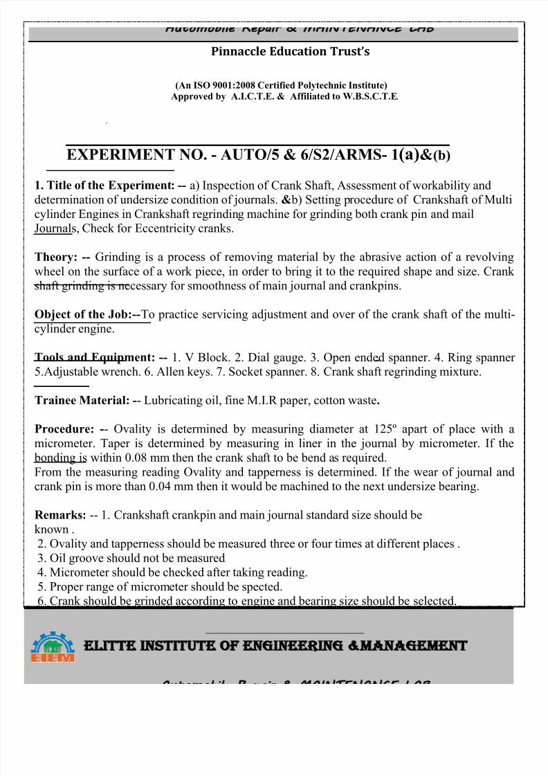
1. Title of the Experiment: -- a) Inspection of Crank Shaft, Assessment of workability anddetermination of undersize condition of journals. & b) Setting procedure of Crankshaft of Multi
cylinder Engines in Crankshaft regrinding machine for grinding both crank pin and mailJournals, Check for Eccentricity cranks.
Theory: -- Grinding is a process of removing material by the abrasive action of a revolving
wheel on the surface of a work piece, in order to bring it to the required shape and size. Crankshaft grinding is necessary for smoothness of main journal and crankpins.
Object of the Job:--To practice servicing adjustment and over of the crank shaft of the multi-
cylinder engine.
Tools and Equipment: -- 1. V Block. 2. Dial gauge. 3. Open ended spanner. 4. Ring spanner5.Adjustable wrench. 6. Allen keys. 7. Socket spanner. 8. Crank shaft regrinding mixture.
Trainee Material: -- Lubricating oil, fine M.I.R paper, cotton waste.
Procedure: -- Ovality is determined by measuring diameter at 125º apart of place with a
micrometer. Taper is determined by measuring in liner in the journal by micrometer. If the
bonding is within 0.08 mm then the crank shaft to be bend as required.
From the measuring reading Ovality and tapperness is determined. If the wear of journal andcrank pin is more than 0.04 mm then it would be machined to the next undersize bearing.
Remarks: -- 1. Crankshaft crankpin and main journal standard size should be
known .
2. Ovality and tapperness should be measured three or four times at different places .3. Oil groove should not be measured4. Micrometer should be checked after taking reading.
5. Proper range of micrometer should be spected.6. Crank should be grinded according to engine and bearing size should be selected.
8/13/2019 Repair Maintenance
http://slidepdf.com/reader/full/repair-maintenance 2/34
Pinnaccle Education Trust’s ELITTE INSTITUTE OF ENGINEERING MANAGEMENT
(An ISO 9001:2008 Certified Polytechnic Institute)Approved by A.I.C.T.E. & Affiliated to W.B.S.C.T.E. Automobile Repair MAINTENANCE LAB
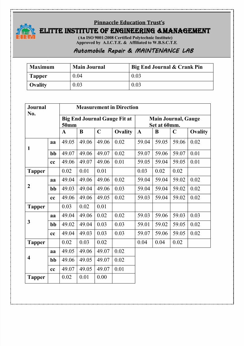
Maximum Main Journal Big End Journal & Crank Pin
Tapper 0.04 0.03
Ovality 0.03 0.03
Journal
No.
Measurement in Direction
Big End Journal Gauge Fit at50mm Main Journal, GaugeSet at 60mm.
A B C Ovality A B C Ovality
1
aa 49.05 49.06 49.06 0.02 59.04 59.05 59.06 0.02
bb 49.07 49.06 49.07 0.02 59.07 59.06 59.07 0.01
cc 49.06 49.07 49.06 0.01 59.05 59.04 59.05 0.01
Tapper 0.02 0.01 0.01 0.03 0.02 0.02
2 aa 49.04 49.06 49.06 0.02 59.04 59.04 59.02 0.02bb 49.03 49.04 49.06 0.03 59.04 59.04 59.02 0.02
cc 49.06 49.06 49.05 0.02 59.03 59.04 59.02 0.02
Tapper 0.03 0.02 0.01
3
aa 49.04 49.06 0.02 0.02 59.03 59.06 59.03 0.03
bb 49.02 49.04 0.03 0.03 59.01 59.02 59.05 0.02
cc 49.04 49.03 0.03 0.03 59.07 59.06 59.05 0.02
Tapper 0.02 0.03 0.02 0.04 0.04 0.02
4
aa 49.05 49.06 49.07 0.02
bb 49.06 49.05 49.07 0.02
cc 49.07 49.05 49.07 0.01
Tapper 0.02 0.01 0.00
8/13/2019 Repair Maintenance
http://slidepdf.com/reader/full/repair-maintenance 3/34
Pinnaccle Education Trust’s ELITTE INSTITUTE OF ENGINEERING MANAGEMENT
(An ISO 9001:2008 Certified Polytechnic Institute)Approved by A.I.C.T.E. & Affiliated to W.B.S.C.T.E. Automobile Repair MAINTENANCE LAB
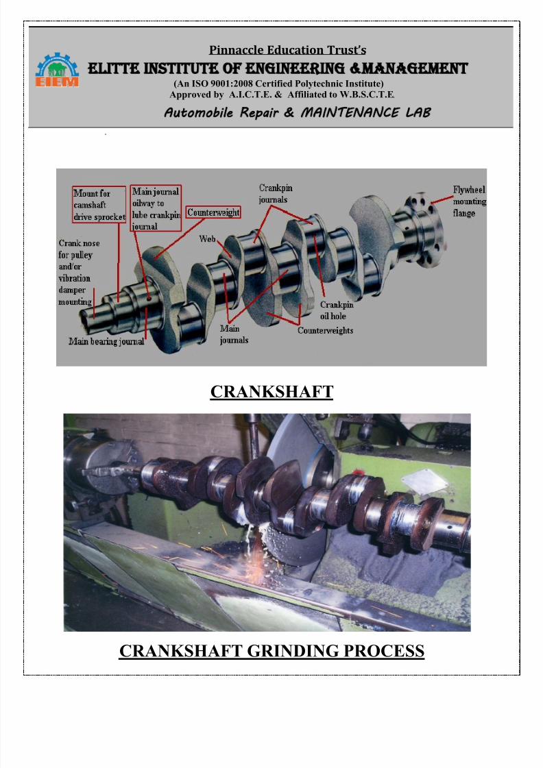
CRANKSHAFT
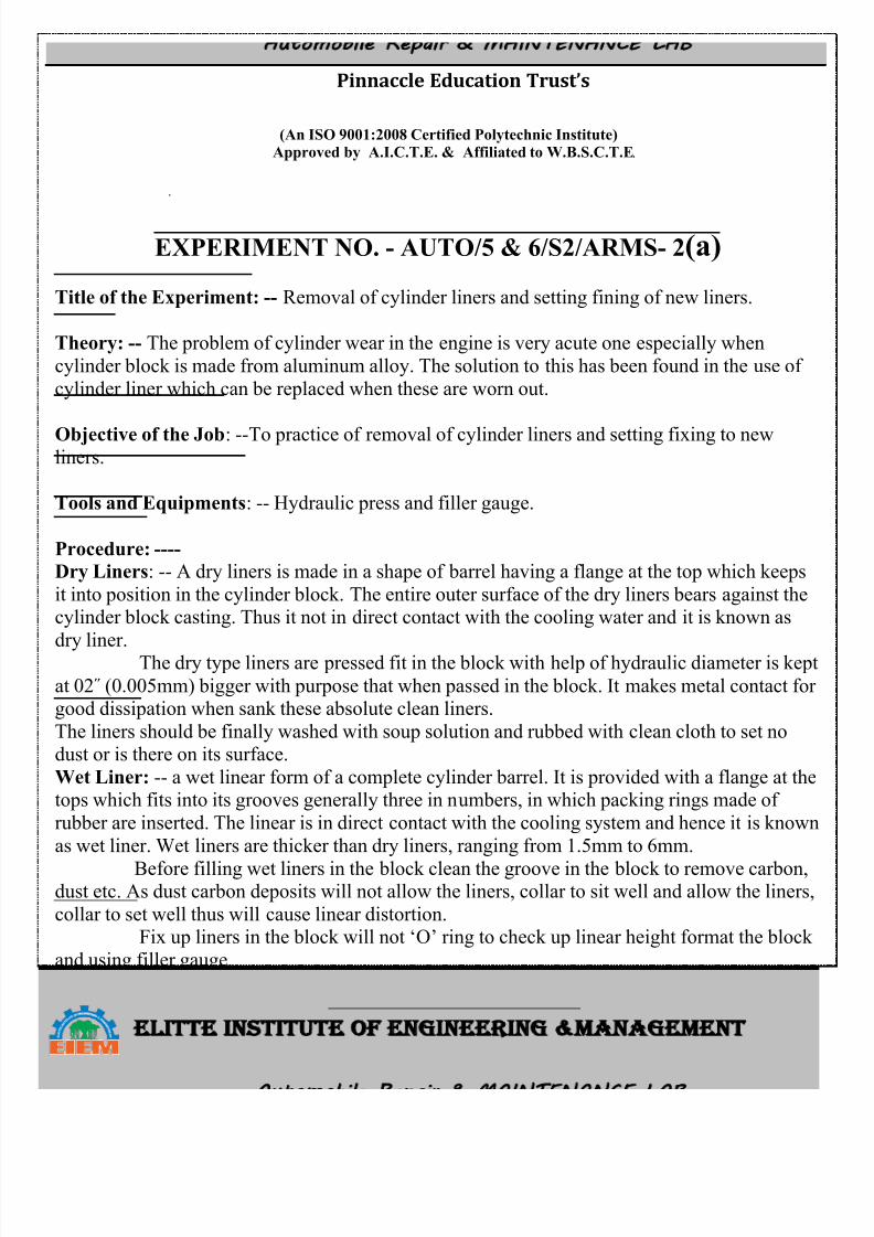
CRANKSHAFT GRINDING PROCESS
8/13/2019 Repair Maintenance
http://slidepdf.com/reader/full/repair-maintenance 4/34
Pinnaccle Education Trust’s ELITTE INSTITUTE OF ENGINEERING MANAGEMENT
(An ISO 9001:2008 Certified Polytechnic Institute)Approved by A.I.C.T.E. & Affiliated to W.B.S.C.T.E. Automobile Repair MAINTENANCE LAB
EXPERIMENT NO. - AUTO/5 & 6/S2/ARMS- 2(a)
Title of the Experiment: -- Removal of cylinder liners and setting fining of new liners.
Theory: -- The problem of cylinder wear in the engine is very acute one especially when
cylinder block is made from aluminum alloy. The solution to this has been found in the use of
cylinder liner which can be replaced when these are worn out.
Objective of the Job: --To practice of removal of cylinder liners and setting fixing to newliners.
Tools and Equipments: -- Hydraulic press and filler gauge.
Procedure: ----
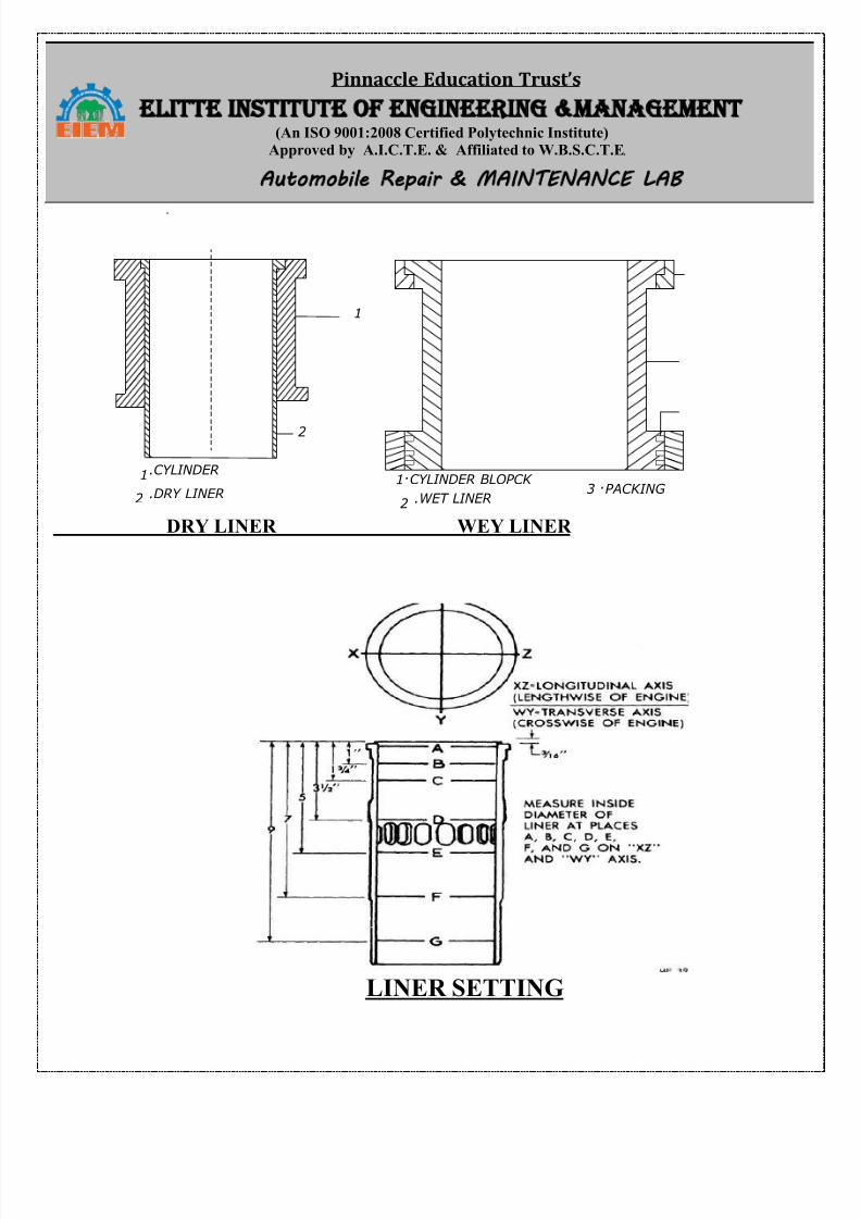
Dry Liners: -- A dry liners is made in a shape of barrel having a flange at the top which keeps
it into position in the cylinder block. The entire outer surface of the dry liners bears against thecylinder block casting. Thus it not in direct contact with the cooling water and it is known as
dry liner. The dry type liners are pressed fit in the block with help of hydraulic diameter is kept
at 02˝ (0.005mm) bigger with purpose that when passed in the block. It makes metal contact forgood dissipation when sank these absolute clean liners.
The liners should be finally washed with soup solution and rubbed with clean cloth to set nodust or is there on its surface.
Wet Liner: -- a wet linear form of a complete cylinder barrel. It is provided with a flange at thetops which fits into its grooves generally three in numbers, in which packing rings made of
rubber are inserted. The linear is in direct contact with the cooling system and hence it is known
as wet liner. Wet liners are thicker than dry liners, ranging from 1.5mm to 6mm.
Before filling wet liners in the block clean the groove in the block to remove carbon,dust etc. As dust carbon deposits will not allow the liners, collar to sit well and allow the liners,
collar to set well thus will cause linear distortion.Fix up liners in the block will not „O‟ ring to check up linear height format the block
and using filler gauge.
Remarks: -- 1. Care should be taken to clean the cylinder.2. Before filling liners clean the covers grooves.
8/13/2019 Repair Maintenance
http://slidepdf.com/reader/full/repair-maintenance 5/34
Pinnaccle Education Trust’s ELITTE INSTITUTE OF ENGINEERING MANAGEMENT
(An ISO 9001:2008 Certified Polytechnic Institute)Approved by A.I.C.T.E. & Affiliated to W.B.S.C.T.E. Automobile Repair MAINTENANCE LAB
1
2
1
2
1
2
3
CYLINDER
DRY LINER
CYLINDER BLOPCK
WET LINERPACKING .
.
..
.
DRY LINER WEY LINER
LINER SETTING
8/13/2019 Repair Maintenance
http://slidepdf.com/reader/full/repair-maintenance 6/34
Pinnaccle Education Trust’s ELITTE INSTITUTE OF ENGINEERING MANAGEMENT
(An ISO 9001:2008 Certified Polytechnic Institute)Approved by A.I.C.T.E. & Affiliated to W.B.S.C.T.E. Automobile Repair MAINTENANCE LAB
EXPERIMENT NO. - AUTO/5 & 6/S2/ARMS- 3
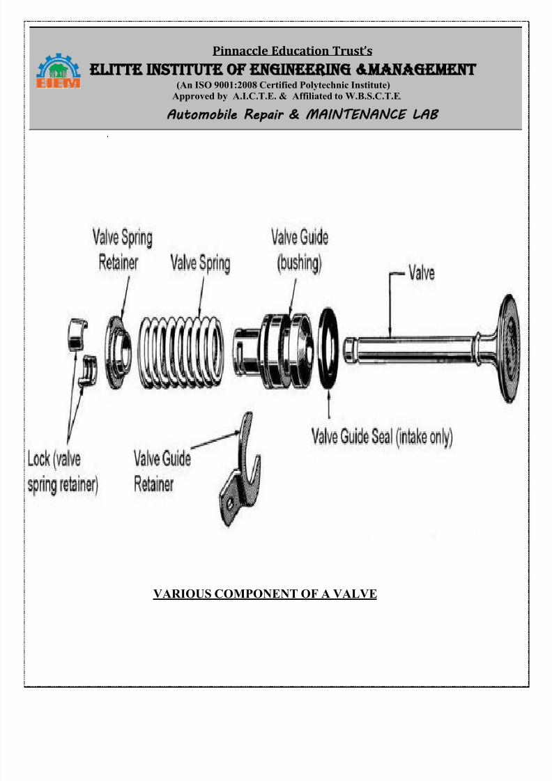
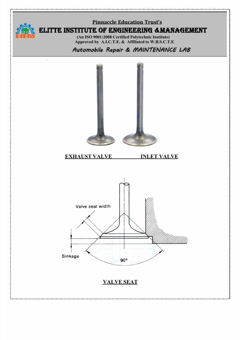
Title of the Experiment: -- Valve refacing in Valve refacer machine, Valve Seat cutting settingand grinding to match with valves. Lapping of valves.
Theory: -- Valve is a device to close and open a passage. In motor vehicle engines, two valvesare used for each cylinder – an inlet valve and an exhaust valve. Fuel is admitted to the cylinder
by the inlet valve and burned gasses escape by the exhaust valve.Object of the Job: -- Removing the valve from the engine, grinding valve and valve seat,
checking clearance and refitting.
Tools and Equipments: --
1.Valve refacing machine.
2. Valve seat cutter3. Valve seat grinder
4. Grinding stone pest
Procedure: -- i) Clean & check valve.ii) Some valve ware more & some valve were less fitted, replace more valves where as less
valve were kept on bench.iii) Removed Carbon deposited on valves.
iv) Adjust the angle before starting refacing operation and as per manufacturer instruction.v) Brought valve close to grinding wheel and maintain the gap between them.
vi) Switch on the machine and also switch on the motor which rotates valves.vii) Replace valve of vehicle one by one.
viii) Valve seat should be cut with sheet cutting and grinding after refreshing.ix) Measure valve seat angle with the help of seat cutter.
x) Fitted handle and to valve seat cutter.
xi) Cut the seat.xii) Fitted inside cutter to handle and also.xiii) Inserted new valves and made lapping.
Remarks: -- 1. If valve is more fitted then it should not be grained.2. Valve should be loose in cutter
3. Valve should be in centre in gravity stone.4. Valve angle should new before replacing.
5. Cutter should be operated in straight member.6. Least margined seat should be replaced and it should not be reconditioning.
8/13/2019 Repair Maintenance
http://slidepdf.com/reader/full/repair-maintenance 7/34
Pinnaccle Education Trust’s ELITTE INSTITUTE OF ENGINEERING MANAGEMENT
(An ISO 9001:2008 Certified Polytechnic Institute)Approved by A.I.C.T.E. & Affiliated to W.B.S.C.T.E. Automobile Repair MAINTENANCE LAB
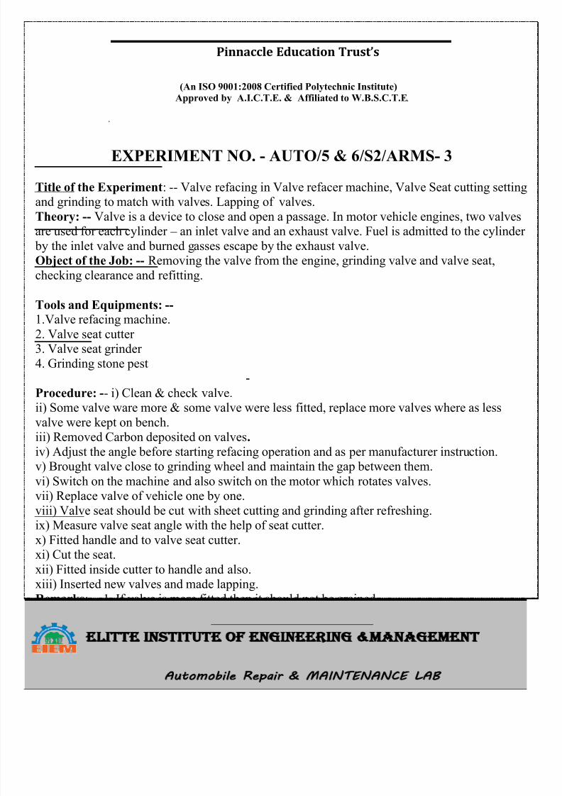
VARIOUS COMPONENT OF A VALVE
8/13/2019 Repair Maintenance
http://slidepdf.com/reader/full/repair-maintenance 8/34
8/13/2019 Repair Maintenance
http://slidepdf.com/reader/full/repair-maintenance 9/34
Pinnaccle Education Trust’s ELITTE INSTITUTE OF ENGINEERING MANAGEMENT
(An ISO 9001:2008 Certified Polytechnic Institute)Approved by A.I.C.T.E. & Affiliated to W.B.S.C.T.E. Automobile Repair MAINTENANCE LAB
EXPERIMENT NO. - AUTO/5& 6/S2/ARMS- 4(a)
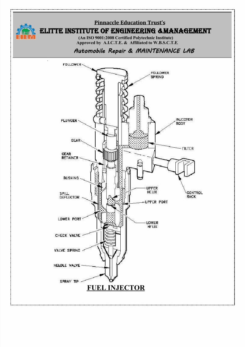
Title of the Experiment: -- To Testing of fuel Injectors in fuel Injector Tester.
Theory: -- The function of fuel injector is to inject the fuel in the cylinder in properly atomized
form and in proper quantity.
Objective of the Job: -- To practice the checking of fuel injector tester.
Trainee Material: -- Diesel oil, clean jute.
Procedure: --
Pressure Test: -- While studying the working of engines it was tested that the injector spray
diesel oil in a fine atomized form just before the piston reaches the TDC in compression strokethree tests are done in injector testing machine to test on injector.
Clamp the injector on the tester and operate tester pump, note the reading of the dial gauge atwhich the injector nozzle starts spraying. It gives the pressure reading. It should be same as
recommended by the manufacturer. If it is less tighten than the adjusting screw of the injector.If it is more loosen than the adjusting screw.
Finally tighten the lock nut.Leak Test: -- Clamp the injector on the tester and build up the pressure about 150 kg / cm² by
operating the tester pump.Keep this pressure for about 10 seconds. If the pressure If the pressure drops it shows that there
is leakage in the injectors. Check the mazzle valve, needle and nozzle body. Correct the nozzleseat and needle by grinding and lapping and after that again to the leak off test.
Spray Test: -- spray test is also done in the same injector testing machine while operating the
tester pump check carefully the spray. It should not be like a current of oil or with drops
splitting away, but it should be fully atomized.
Remarks: -- 1. Check if the injector is properly set on the testing machine.2. For this test the manual should be followed.
3. Carefully notice the test.
8/13/2019 Repair Maintenance
http://slidepdf.com/reader/full/repair-maintenance 10/34
Pinnaccle Education Trust’s ELITTE INSTITUTE OF ENGINEERING MANAGEMENT
(An ISO 9001:2008 Certified Polytechnic Institute)Approved by A.I.C.T.E. & Affiliated to W.B.S.C.T.E. Automobile Repair MAINTENANCE LAB
FUEL INJECTOR
8/13/2019 Repair Maintenance
http://slidepdf.com/reader/full/repair-maintenance 11/34
Pinnaccle Education Trust’s ELITTE INSTITUTE OF ENGINEERING MANAGEMENT
(An ISO 9001:2008 Certified Polytechnic Institute)Approved by A.I.C.T.E. & Affiliated to W.B.S.C.T.E. Automobile Repair MAINTENANCE LAB
EXPERIMENT NO. - AUTO/5 & 6/S2/ARMS- 4(b)
Title of the Experiment: -- Phasing and calibration of F.I.P.
Objective of the Job: - Removing, dismantling, cleaning, assembling and testing of fuel
injection pump.
Tools and Equipment: -- 1. Double ended spanner set. 2. Flat head screw driver. 3. Tray. 4.
Swam neck pipe. Socket set. 6. Hammer. 7. Dial test indicator. 8. Calibration machine. 9.Phasing oil.
Procedure: ----
Phasing: -- 1. Mounted F.I.P. on calibration machine.
2. Starting operation as per firing order to engine.3. Dismantled inspection plate and holder assembly as per firing order.
4. Treated sawn neck pipe to the holder & started fuel supply. After 10kg. The supply becomestop.
5. The fuel supply was stopping before 35°, which should become at 60º. The reason behind itis small tapered clearance.
Calibration: -- 1.Connected master injectors of calibration to respective holder of F.I.P2. Adjust rpm of stroke.
3. Adjust by quadrant sleeve towards.4. Tighten screw of respective quadrants.
5. Tighten bleeding nipple.6. Remove split cut pipe and mounted delivery valve assembly spraying and holder.
7. Cranked the engine, brought cylinder no. 1. piston to TDC and matched flywheel limiting
mark in front of pointer.
Remarks: -- 1. Phasing and calibration instruction of related manufacture should be followed.
2. After calibration all toothed quadrant should be tighten.
8/13/2019 Repair Maintenance
http://slidepdf.com/reader/full/repair-maintenance 12/34
Pinnaccle Education Trust’s ELITTE INSTITUTE OF ENGINEERING MANAGEMENT
(An ISO 9001:2008 Certified Polytechnic Institute)Approved by A.I.C.T.E. & Affiliated to W.B.S.C.T.E. Automobile Repair MAINTENANCE LAB
EXPERIMENT NO. - AUTO/5 & 6/S2/ARMS- 5
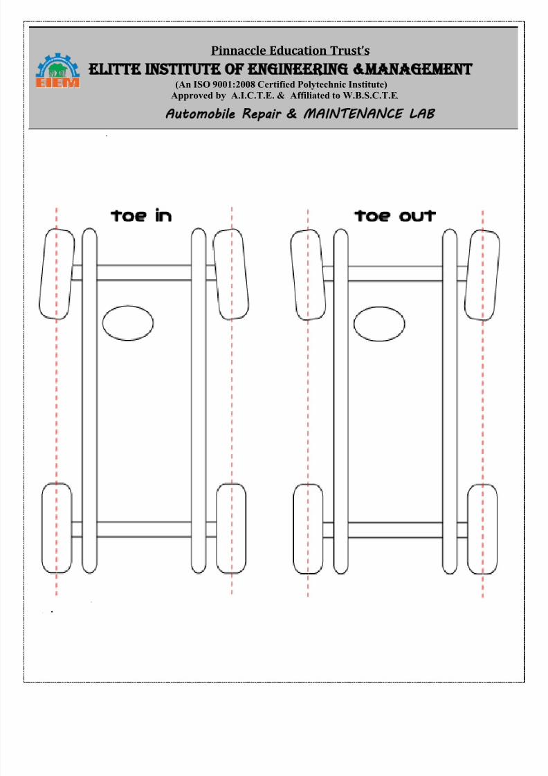
Title of the Experiment: -- Steering Geometry-Checking and adjustment of camber, caster,toe-in, toe-out, KPI, SAI.
Theory: -- The functions of steering geometry are it provides directional stability, it helps
controlling wear and tear of tyres.
Object of the Job: -- checking and adjustment of wheel alignment using video graphiccomputerized machine.
Tools and Equipment Used: -- 1.Double ended spanner set. 2. Precision.3. Video graphic
computerized machine.
Raw Material Used: -- Cotton waste.
Procedure: -- 1.At first packed the vehicle with its front table.2. Fitted both to both sim.
3. The vehicle with string, starting from one front wheel to the other through both rearwheels.
4. Switch on of the monitor.5. There are 5 details on the mence.
A. Measurement, B. Front self calibration. C. Rear self calibration. D. Records of new method.E. Service.
6. After setting all attachment, we find error of camber tester, toe-in and toe-out with the help ofspanner, wrenches; readjust the specified valves of different alignment setting.
7. Print the fresh copy of alignment valve of the vehicles.
Precaution: --1. Checked and fitted specified air pressure.
2. Wheel sim or any component should not be bent.3. Wheel alignment floor should be zero value.
4. Machine should be placed properly.5. Don‟t forget to press, rest, after one revolution.
8/13/2019 Repair Maintenance
http://slidepdf.com/reader/full/repair-maintenance 13/34
Pinnaccle Education Trust’s ELITTE INSTITUTE OF ENGINEERING MANAGEMENT
(An ISO 9001:2008 Certified Polytechnic Institute)Approved by A.I.C.T.E. & Affiliated to W.B.S.C.T.E. Automobile Repair MAINTENANCE LAB
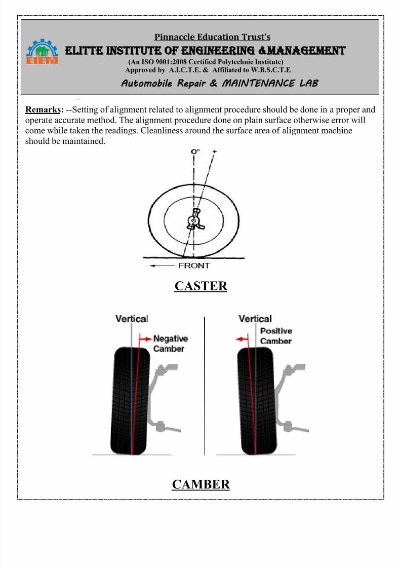
Remarks: --Setting of alignment related to alignment procedure should be done in a proper and
operate accurate method. The alignment procedure done on plain surface otherwise error willcome while taken the readings. Cleanliness around the surface area of alignment machine
should be maintained.
CASTER
CAMBER
8/13/2019 Repair Maintenance
http://slidepdf.com/reader/full/repair-maintenance 14/34
Pinnaccle Education Trust’s ELITTE INSTITUTE OF ENGINEERING MANAGEMENT
(An ISO 9001:2008 Certified Polytechnic Institute)Approved by A.I.C.T.E. & Affiliated to W.B.S.C.T.E. Automobile Repair MAINTENANCE LAB
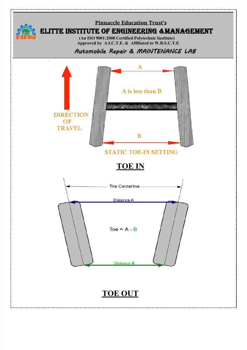
TOE IN
TOE OUT
8/13/2019 Repair Maintenance
http://slidepdf.com/reader/full/repair-maintenance 15/34
Pinnaccle Education Trust’s ELITTE INSTITUTE OF ENGINEERING MANAGEMENT
(An ISO 9001:2008 Certified Polytechnic Institute)Approved by A.I.C.T.E. & Affiliated to W.B.S.C.T.E. Automobile Repair MAINTENANCE LAB
8/13/2019 Repair Maintenance
http://slidepdf.com/reader/full/repair-maintenance 16/34
Pinnaccle Education Trust’s ELITTE INSTITUTE OF ENGINEERING MANAGEMENT
(An ISO 9001:2008 Certified Polytechnic Institute)Approved by A.I.C.T.E. & Affiliated to W.B.S.C.T.E. Automobile Repair MAINTENANCE LAB
EXPERIMENT NO. - AUTO/5& 6/S2/ARMS- 6(a)
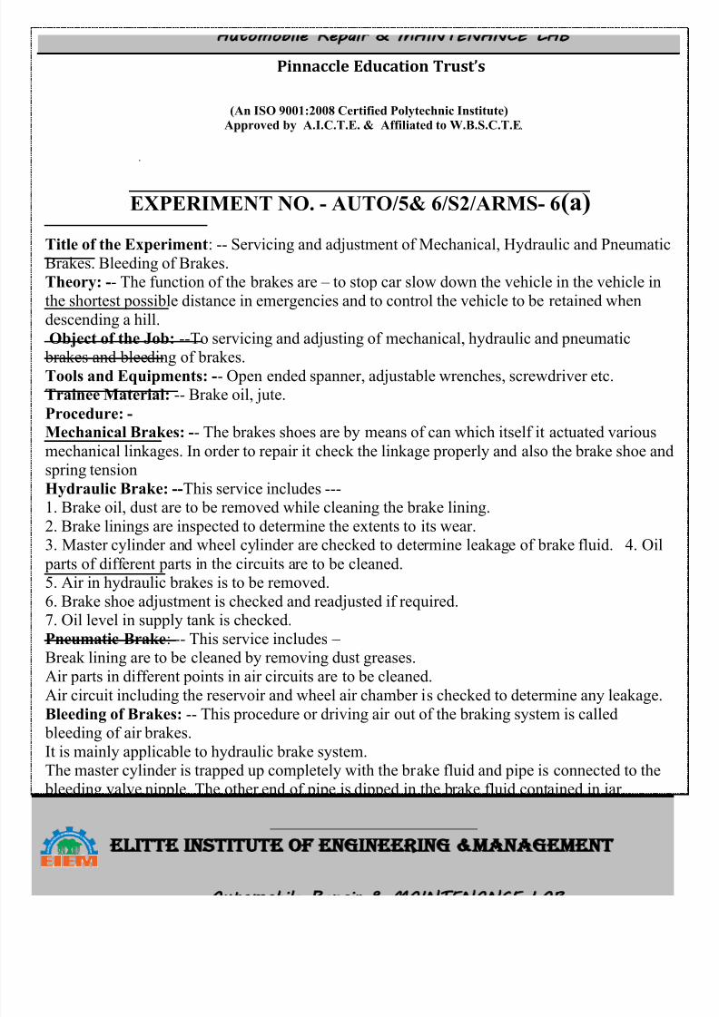
Title of the Experiment: -- Servicing and adjustment of Mechanical, Hydraulic and Pneumatic
Brakes. Bleeding of Brakes.Theory: -- The function of the brakes are – to stop car slow down the vehicle in the vehicle in
the shortest possible distance in emergencies and to control the vehicle to be retained when
descending a hill.
Object of the Job: --To servicing and adjusting of mechanical, hydraulic and pneumatic
brakes and bleeding of brakes. Tools and Equipments: -- Open ended spanner, adjustable wrenches, screwdriver etc.Trainee Material: -- Brake oil, jute.
Procedure: -
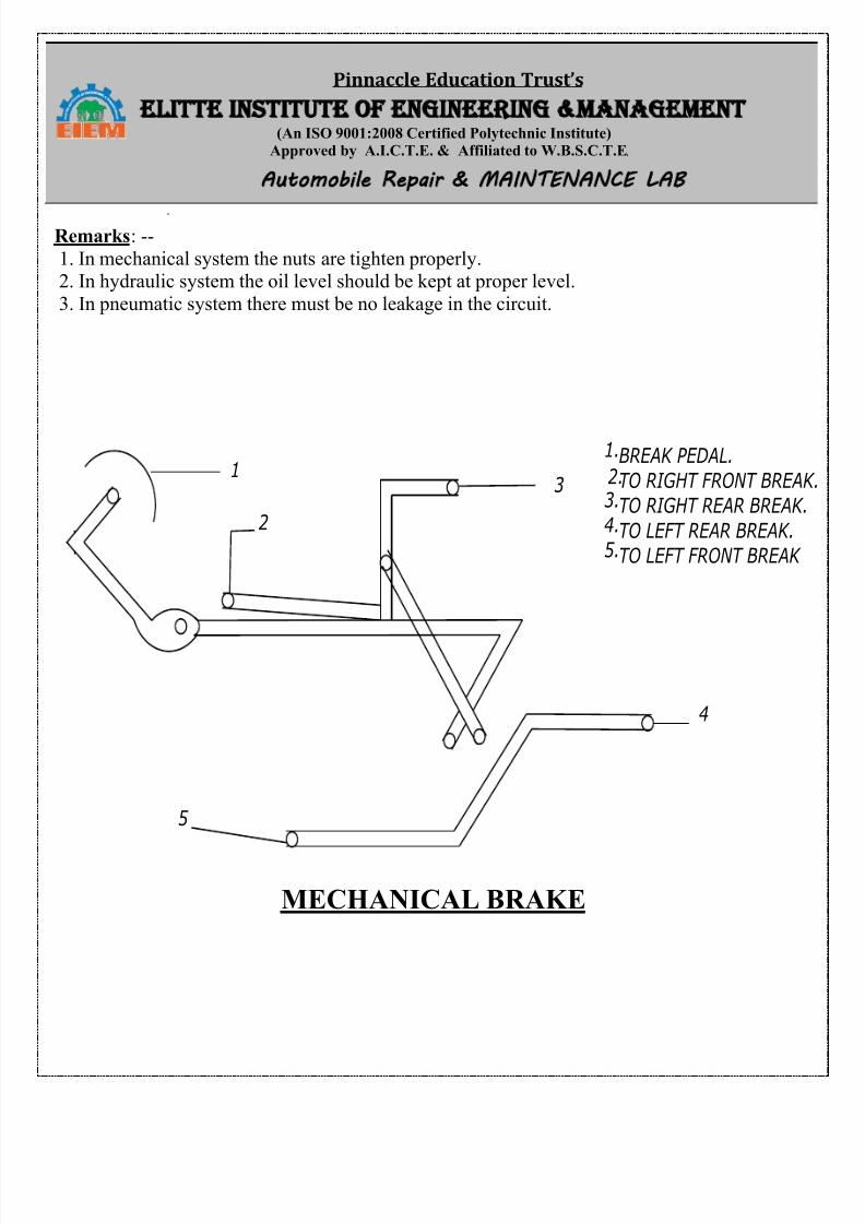
Mechanical Brakes: -- The brakes shoes are by means of can which itself it actuated various
mechanical linkages. In order to repair it check the linkage properly and also the brake shoe andspring tension
Hydraulic Brake: --This service includes ---1. Brake oil, dust are to be removed while cleaning the brake lining.
2. Brake linings are inspected to determine the extents to its wear.3. Master cylinder and wheel cylinder are checked to determine leakage of brake fluid. 4. Oil
parts of different parts in the circuits are to be cleaned.5. Air in hydraulic brakes is to be removed.
6. Brake shoe adjustment is checked and readjusted if required.7. Oil level in supply tank is checked.
Pneumatic Brake: -- This service includes – Break lining are to be cleaned by removing dust greases.
Air parts in different points in air circuits are to be cleaned.
Air circuit including the reservoir and wheel air chamber is checked to determine any leakage.
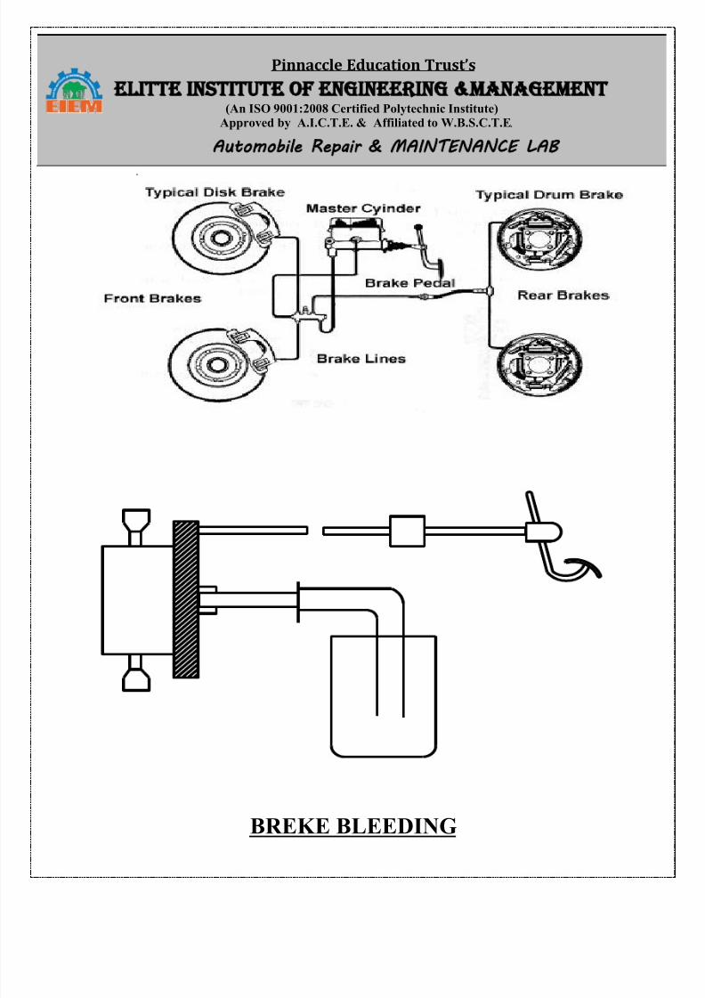
Bleeding of Brakes: -- This procedure or driving air out of the braking system is called bleeding of air brakes.
It is mainly applicable to hydraulic brake system.The master cylinder is trapped up completely with the brake fluid and pipe is connected to the
bleeding valve nipple. The other end of pipe is dipped in the brake fluid contained in jar.
One person seat on the driver seat and press the brake pedal, the bleeder valve is opened by the
second person with a spanner when some air bubble come out, brake paddle released and pressed again and again.
8/13/2019 Repair Maintenance
http://slidepdf.com/reader/full/repair-maintenance 17/34
Pinnaccle Education Trust’s ELITTE INSTITUTE OF ENGINEERING MANAGEMENT
(An ISO 9001:2008 Certified Polytechnic Institute)Approved by A.I.C.T.E. & Affiliated to W.B.S.C.T.E. Automobile Repair MAINTENANCE LAB
Remarks: --
1. In mechanical system the nuts are tighten properly.2. In hydraulic system the oil level should be kept at proper level.
3. In pneumatic system there must be no leakage in the circuit.
1
2
3
4
5
BREAK PEDAL.
TO RIGHT FRONT BREAK
TO RIGHT REAR BREAK.
TO LEFT REAR BREAK.
TO LEFT FRONT BREAK
1.
2.
3.
4.
5.
MECHANICAL BRAKE
8/13/2019 Repair Maintenance
http://slidepdf.com/reader/full/repair-maintenance 18/34
Pinnaccle Education Trust’s ELITTE INSTITUTE OF ENGINEERING MANAGEMENT
(An ISO 9001:2008 Certified Polytechnic Institute)Approved by A.I.C.T.E. & Affiliated to W.B.S.C.T.E. Automobile Repair MAINTENANCE LAB
BREKE BLEEDING
8/13/2019 Repair Maintenance
http://slidepdf.com/reader/full/repair-maintenance 19/34
Pinnaccle Education Trust’s ELITTE INSTITUTE OF ENGINEERING MANAGEMENT
(An ISO 9001:2008 Certified Polytechnic Institute)Approved by A.I.C.T.E. & Affiliated to W.B.S.C.T.E. Automobile Repair MAINTENANCE LAB
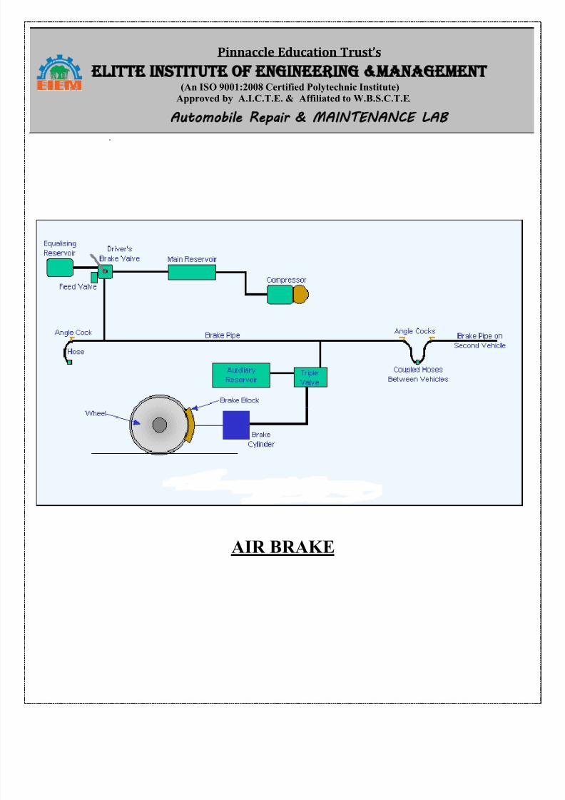
AIR BRAKE
8/13/2019 Repair Maintenance
http://slidepdf.com/reader/full/repair-maintenance 20/34
Pinnaccle Education Trust’s ELITTE INSTITUTE OF ENGINEERING MANAGEMENT
(An ISO 9001:2008 Certified Polytechnic Institute)Approved by A.I.C.T.E. & Affiliated to W.B.S.C.T.E. Automobile Repair MAINTENANCE LAB
EXPERIMENT NO. - AUTO/5 & 6/S2/ARMS- 6(b)
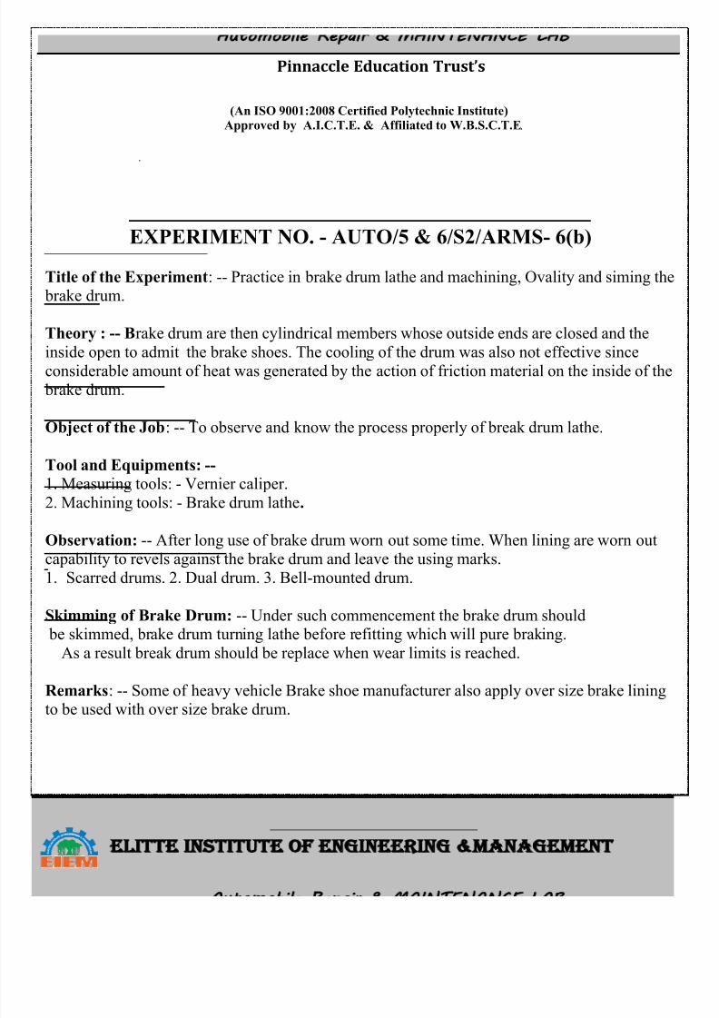
Title of the Experiment: -- Practice in brake drum lathe and machining, Ovality and siming the brake drum.
Theory : -- Brake drum are then cylindrical members whose outside ends are closed and the
inside open to admit the brake shoes. The cooling of the drum was also not effective sinceconsiderable amount of heat was generated by the action of friction material on the inside of the
brake drum.
Object of the Job: -- To observe and know the process properly of break drum lathe.
Tool and Equipments: --
1. Measuring tools: - Vernier caliper.
2. Machining tools: - Brake drum lathe.
Observation: -- After long use of brake drum worn out some time. When lining are worn outcapability to revels against the brake drum and leave the using marks.
1. Scarred drums. 2. Dual drum. 3. Bell-mounted drum.
Skimming of Brake Drum: -- Under such commencement the brake drum should be skimmed, brake drum turning lathe before refitting which will pure braking.
As a result break drum should be replace when wear limits is reached.
Remarks: -- Some of heavy vehicle Brake shoe manufacturer also apply over size brake lining
to be used with over size brake drum.
8/13/2019 Repair Maintenance
http://slidepdf.com/reader/full/repair-maintenance 21/34
Pinnaccle Education Trust’s ELITTE INSTITUTE OF ENGINEERING MANAGEMENT
(An ISO 9001:2008 Certified Polytechnic Institute)Approved by A.I.C.T.E. & Affiliated to W.B.S.C.T.E. Automobile Repair MAINTENANCE LAB
BRAKE DRUM
8/13/2019 Repair Maintenance
http://slidepdf.com/reader/full/repair-maintenance 22/34
Pinnaccle Education Trust’s ELITTE INSTITUTE OF ENGINEERING MANAGEMENT
(An ISO 9001:2008 Certified Polytechnic Institute)Approved by A.I.C.T.E. & Affiliated to W.B.S.C.T.E. Automobile Repair MAINTENANCE LAB
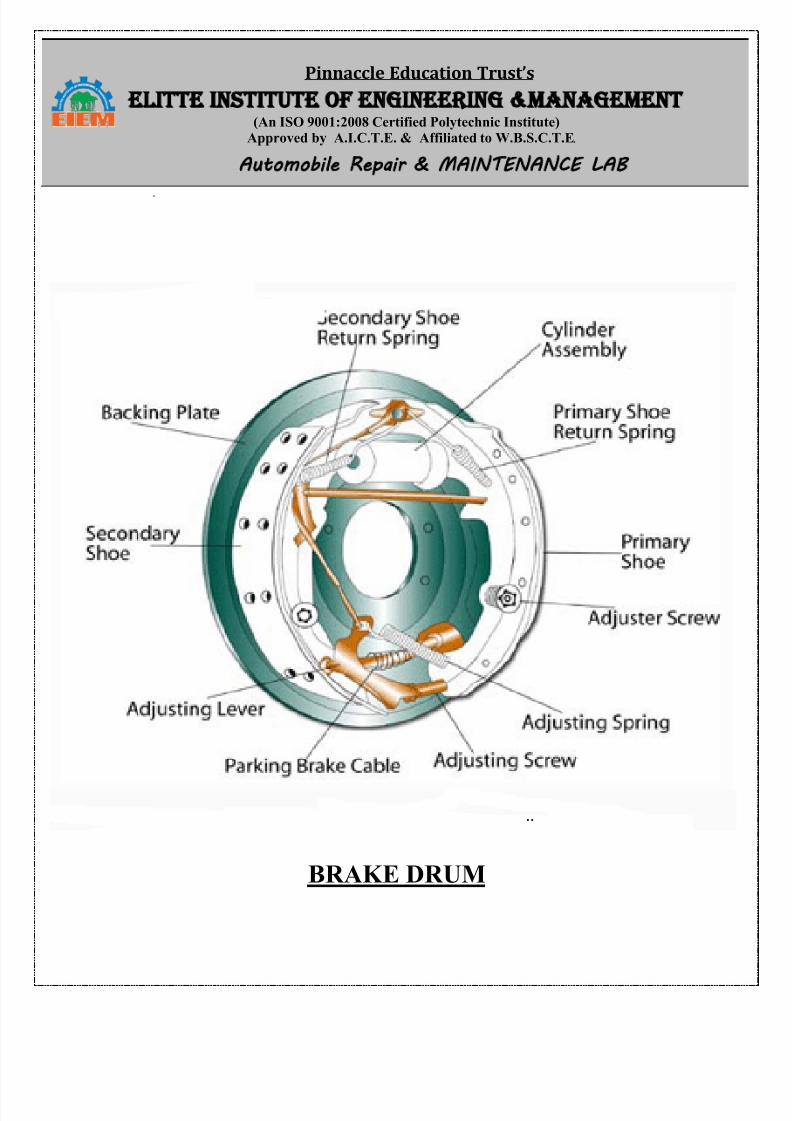
EXPERIMENT NO. - AUTO/5 & 6/S2/ARMS-1
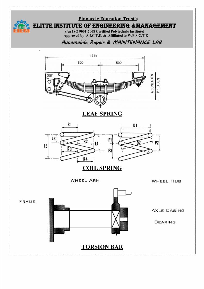
Title of the Experiment: -- Servicing of suspension system, leaf spring coil spring torsion bar
telescopic shock absorber.
Theory: -- Suspension system mounted on the vehicle for prevent the road shocks from being
transmitted to the vehicle frame, to preserve the stability of the vehicle in pitching or rolling,
while in motion. To safe guard the occupants from road shock and maintain proper steering
geometry.
Object of the Job: -- To remove dismantling, cleaning and refitting the leaf spring.
Tools and Equipment Used: -- 1. Double ended spanner set. 2. Ring spanner set. 3.
Combination plier. 4. Hydraulic jack. 5. Ball pin hammer. 6. Wooden block etc.
Trainee Material: -- 1.Grease. 2. Emary paper. 3. Kerosene oil. 4. Rubber bush kit.
Procedure: -- 1. Shoe absorber which was mounted between frame and leaf spring was takenout using double ended spanner
2. Using wheel base, wheel nut was loosen.3. Wheel assembly was taken out by jacken the vehicle up by fitting it through hydraulic jack.
4. Jack was taken out.5. Differential assembly was made to rest on wooden block.
6. Tension of leaf spring was checked and it is found ok.7. After then “U” clamp fitted properly.
Leaf spring assembly was fitted to vehicle by inserting pivot pin and shakel pin there by
bracket.
Fitted wheel assembly on hub and tighten wheel nut.Lowered the jack and wheel rest ground.
Remarks: -- 1. Clamp must be used while dismantling the leaf spring.
2. Check out, a locking device must be made with nut of “U” bolt.
3. Shock absorber must be installed in leaf lost and locked properly.
8/13/2019 Repair Maintenance
http://slidepdf.com/reader/full/repair-maintenance 23/34
Pinnaccle Education Trust’s ELITTE INSTITUTE OF ENGINEERING MANAGEMENT
(An ISO 9001:2008 Certified Polytechnic Institute)Approved by A.I.C.T.E. & Affiliated to W.B.S.C.T.E. Automobile Repair MAINTENANCE LAB
LEAF SPRING
COIL SPRING
TORSION BAR
8/13/2019 Repair Maintenance
http://slidepdf.com/reader/full/repair-maintenance 24/34
Pinnaccle Education Trust’s ELITTE INSTITUTE OF ENGINEERING MANAGEMENT
(An ISO 9001:2008 Certified Polytechnic Institute)Approved by A.I.C.T.E. & Affiliated to W.B.S.C.T.E. Automobile Repair MAINTENANCE LAB
EXPERIMENT NO. - AUTO/5 & 6/S2/ARMS-2
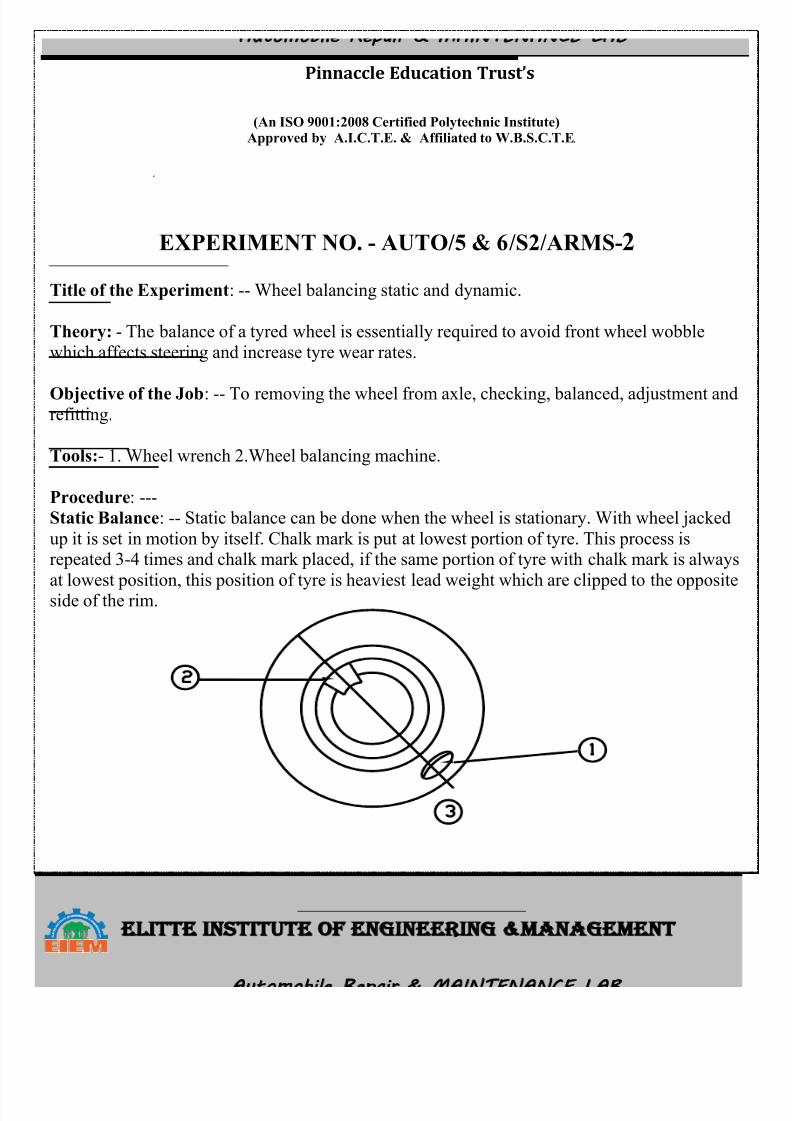
Title of the Experiment: -- Wheel balancing static and dynamic.
Theory: - The balance of a tyred wheel is essentially required to avoid front wheel wobble
which affects steering and increase tyre wear rates.
Objective of the Job: -- To removing the wheel from axle, checking, balanced, adjustment andrefitting.
Tools:- 1. Wheel wrench 2.Wheel balancing machine.
Procedure: ---Static Balance: -- Static balance can be done when the wheel is stationary. With wheel jacked
up it is set in motion by itself. Chalk mark is put at lowest portion of tyre. This process isrepeated 3-4 times and chalk mark placed, if the same portion of tyre with chalk mark is always
at lowest position, this position of tyre is heaviest lead weight which are clipped to the oppositeside of the rim.
8/13/2019 Repair Maintenance
http://slidepdf.com/reader/full/repair-maintenance 25/34
Pinnaccle Education Trust’s ELITTE INSTITUTE OF ENGINEERING MANAGEMENT
(An ISO 9001:2008 Certified Polytechnic Institute)Approved by A.I.C.T.E. & Affiliated to W.B.S.C.T.E. Automobile Repair MAINTENANCE LAB
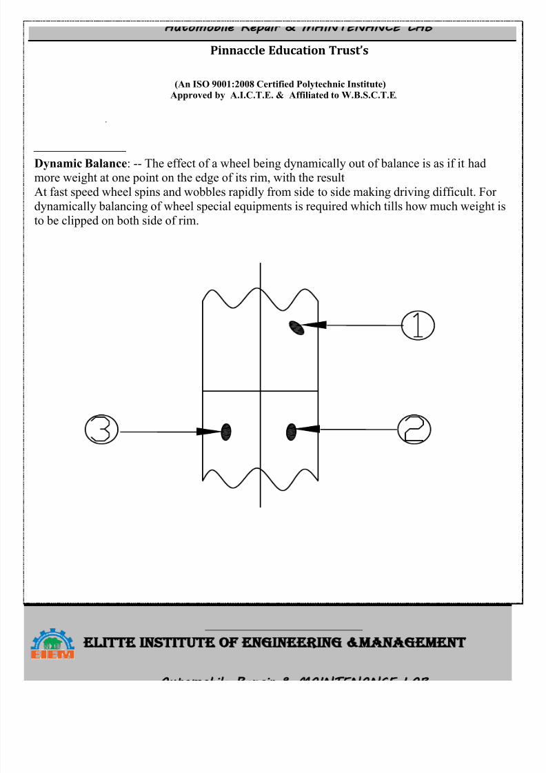
Dynamic Balance: -- The effect of a wheel being dynamically out of balance is as if it hadmore weight at one point on the edge of its rim, with the result
At fast speed wheel spins and wobbles rapidly from side to side making driving difficult. For
dynamically balancing of wheel special equipments is required which tills how much weight is
to be clipped on both side of rim.
8/13/2019 Repair Maintenance
http://slidepdf.com/reader/full/repair-maintenance 26/34
Pinnaccle Education Trust’s ELITTE INSTITUTE OF ENGINEERING MANAGEMENT
(An ISO 9001:2008 Certified Polytechnic Institute)Approved by A.I.C.T.E. & Affiliated to W.B.S.C.T.E. Automobile Repair MAINTENANCE LAB
EXPERIMENT NO. - AUTO/5 & 6/S2/ARMS-3
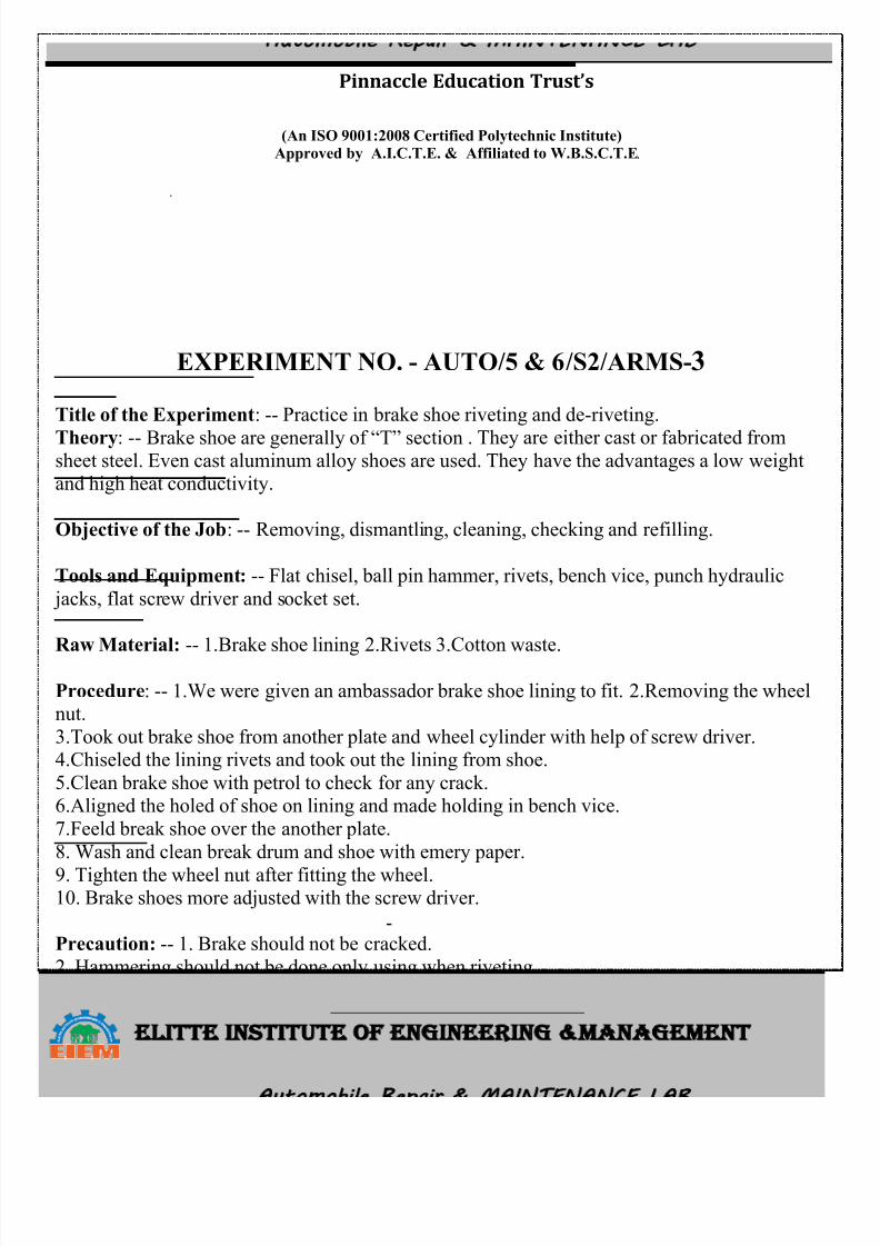
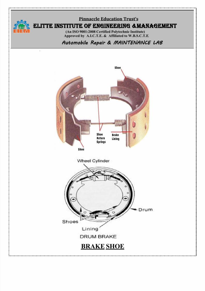
Title of the Experiment: -- Practice in brake shoe riveting and de-riveting.
Theory: -- Brake shoe are generally of “T” section . They are either cast or fabricated fromsheet steel. Even cast aluminum alloy shoes are used. They have the advantages a low weightand high heat conductivity.
Objective of the Job: -- Removing, dismantling, cleaning, checking and refilling.
Tools and Equipment: -- Flat chisel, ball pin hammer, rivets, bench vice, punch hydraulic
jacks, flat screw driver and socket set.
Raw Material: -- 1.Brake shoe lining 2.Rivets 3.Cotton waste.
Procedure: -- 1.We were given an ambassador brake shoe lining to fit. 2.Removing the wheelnut.
3.Took out brake shoe from another plate and wheel cylinder with help of screw driver.4.Chiseled the lining rivets and took out the lining from shoe.
5.Clean brake shoe with petrol to check for any crack.6.Aligned the holed of shoe on lining and made holding in bench vice.
7.Feeld break shoe over the another plate.
8. Wash and clean break drum and shoe with emery paper.
9. Tighten the wheel nut after fitting the wheel.10. Brake shoes more adjusted with the screw driver.
Precaution: -- 1. Brake should not be cracked.
2. Hammering should not be done only using when riveting.
3. If brake shoe are cracked or bend they should replace by new one.
4. Proper brake should always be used.5. Always work with clean and dry hands.
8/13/2019 Repair Maintenance
http://slidepdf.com/reader/full/repair-maintenance 27/34
Pinnaccle Education Trust’s ELITTE INSTITUTE OF ENGINEERING MANAGEMENT
(An ISO 9001:2008 Certified Polytechnic Institute)Approved by A.I.C.T.E. & Affiliated to W.B.S.C.T.E. Automobile Repair MAINTENANCE LAB
BRAKE SHOE
8/13/2019 Repair Maintenance
http://slidepdf.com/reader/full/repair-maintenance 28/34
Pinnaccle Education Trust’s ELITTE INSTITUTE OF ENGINEERING MANAGEMENT
(An ISO 9001:2008 Certified Polytechnic Institute)Approved by A.I.C.T.E. & Affiliated to W.B.S.C.T.E. Automobile Repair MAINTENANCE LAB
EXPERIMENT NO. - AUTO/5 & 6/S2/ARMS-4
Title Of the Experiment: -- Servicing of steering system , different type of steering box ,lockangle, calculation of turning circle radius for different vehicle.
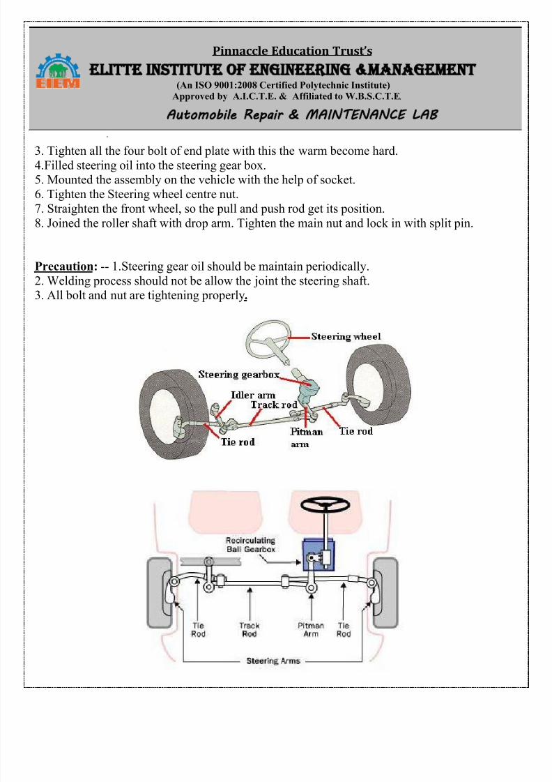
Theory: -- The steering of four wheeled vehicle is as far as possible arranged so that the front
wheels will roll truly with out any slip. The front wheels are support on front axle so that theycan swing to the left or steering for steering. This movement is produced by gearing and linkage
between the steering wheel in front of the driver and the steering knuckle or wheel. Thecomplete arrangement is called steering system.
The function of the steering system is convert the rotary movement of the steering wheel intoangular turn of front wheel. The steering system also absorb a large part of the road shocks.
Object Of The Job : -- To removing ,dismantling ,cleaning ,checking , assembling , adjustment
and fitting.
Tools and Equipments: -- 1.Double ended spanner set. 2.Flat screw driver. 3.Ball pin hammer.4.Feller gauge. 5.Out side micrometer. 6.Hydraulic jack.
Raw Material ; -- 1.Grease 2.Gear oil 3.Bearing patching.
Procedure: -- Jack up front wheel put iron hose under the chassis remove draglink joint from
steering drop arm. Remove steering wheel by unthreading the steering wheel center nut fromsteering shaft. Loosening shaft, bolt, and nut from steering column bracket. Separate steering
gear box and column.Unthreaded the main nut using socket and drop arm was hammered to level the roller shaft.
Took the gear box with wire brush with kerosene remove nut of side plate hammer push roller
set or shaft.
Inspection: -- Washes all components using kerosene .We Found that the balls and edge of
thrust bearing was defective.
Refitting: --
1. New thrust bearing were placed above and below the warm gear which was mounted steeringshaft.
2. Most worm and roller properly and adjusted the backlash using free real adjustment screw.
8/13/2019 Repair Maintenance
http://slidepdf.com/reader/full/repair-maintenance 29/34
Pinnaccle Education Trust’s ELITTE INSTITUTE OF ENGINEERING MANAGEMENT
(An ISO 9001:2008 Certified Polytechnic Institute)Approved by A.I.C.T.E. & Affiliated to W.B.S.C.T.E. Automobile Repair MAINTENANCE LAB
3. Tighten all the four bolt of end plate with this the warm become hard.
4.Filled steering oil into the steering gear box.5. Mounted the assembly on the vehicle with the help of socket.
6. Tighten the Steering wheel centre nut.
7. Straighten the front wheel, so the pull and push rod get its position.
8. Joined the roller shaft with drop arm. Tighten the main nut and lock in with split pin.
Precaution: -- 1.Steering gear oil should be maintain periodically.
2. Welding process should not be allow the joint the steering shaft.3. All bolt and nut are tightening properly.
8/13/2019 Repair Maintenance
http://slidepdf.com/reader/full/repair-maintenance 30/34
Pinnaccle Education Trust’s ELITTE INSTITUTE OF ENGINEERING MANAGEMENT
(An ISO 9001:2008 Certified Polytechnic Institute)Approved by A.I.C.T.E. & Affiliated to W.B.S.C.T.E. Automobile Repair MAINTENANCE LAB
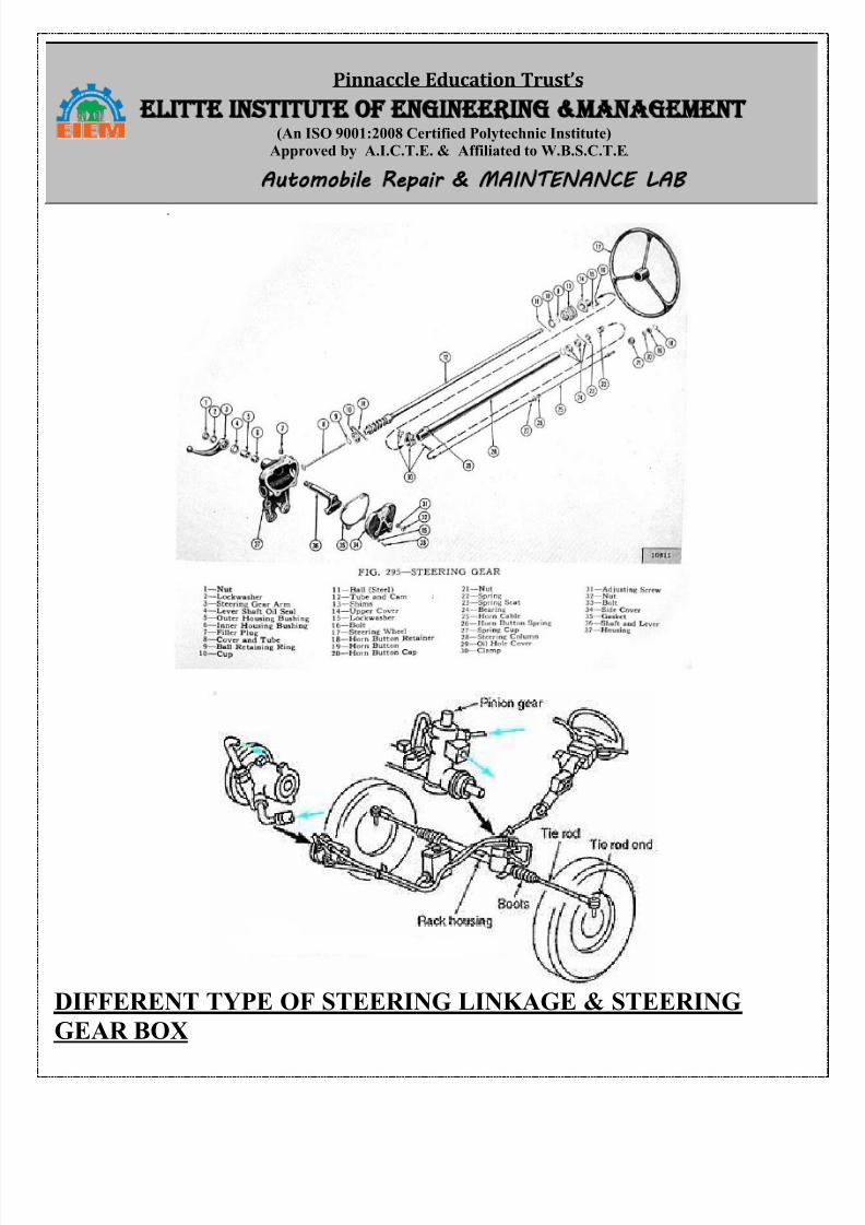
DIFFERENT TYPE OF STEERING LINKAGE & STEERING
GEAR BOX
8/13/2019 Repair Maintenance
http://slidepdf.com/reader/full/repair-maintenance 31/34
Pinnaccle Education Trust’s ELITTE INSTITUTE OF ENGINEERING MANAGEMENT
(An ISO 9001:2008 Certified Polytechnic Institute)Approved by A.I.C.T.E. & Affiliated to W.B.S.C.T.E. Automobile Repair MAINTENANCE LAB
EXPERIMENT NO. - AUTO/5 & 6/S2/ARMS-5
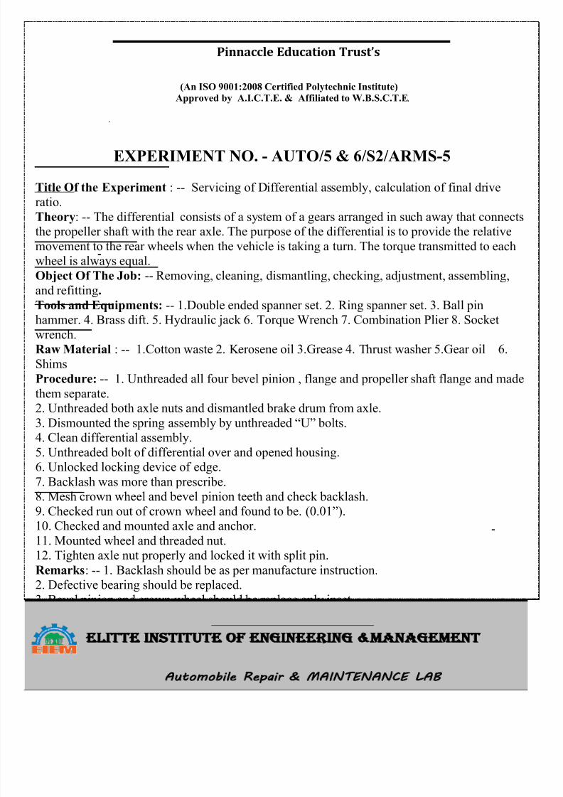
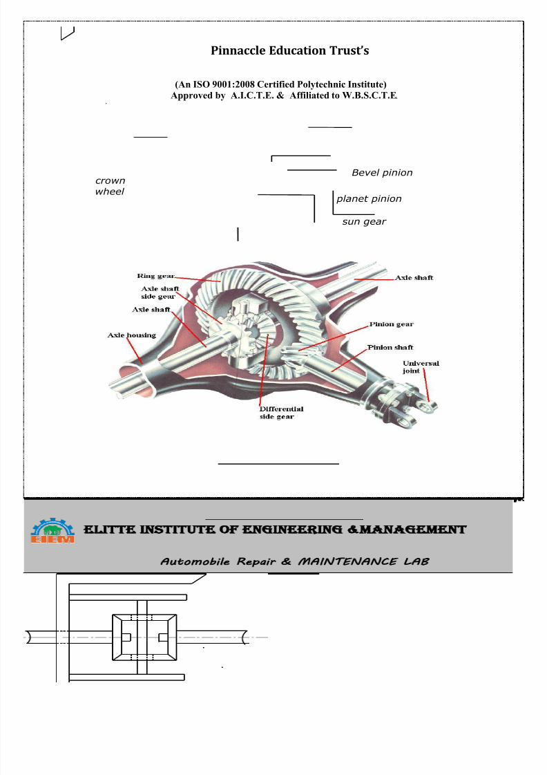
Title Of the Experiment : -- Servicing of Differential assembly, calculation of final driveratio.
Theory: -- The differential consists of a system of a gears arranged in such away that connectsthe propeller shaft with the rear axle. The purpose of the differential is to provide the relative
movement to the rear wheels when the vehicle is taking a turn. The torque transmitted to eachwheel is always equal.
Object Of The Job: -- Removing, cleaning, dismantling, checking, adjustment, assembling,and refitting.
Tools and Equipments: -- 1.Double ended spanner set. 2. Ring spanner set. 3. Ball pinhammer. 4. Brass dift. 5. Hydraulic jack 6. Torque Wrench 7. Combination Plier 8. Socket
wrench.Raw Material : -- 1.Cotton waste 2. Kerosene oil 3.Grease 4. Thrust washer 5.Gear oil 6.
Shims
Procedure: -- 1. Unthreaded all four bevel pinion , flange and propeller shaft flange and made
them separate.2. Unthreaded both axle nuts and dismantled brake drum from axle.
3. Dismounted the spring assembly by unthreaded “U” bolts. 4. Clean differential assembly.
5. Unthreaded bolt of differential over and opened housing.6. Unlocked locking device of edge.
7. Backlash was more than prescribe.8. Mesh crown wheel and bevel pinion teeth and check backlash.
9. Checked run out of crown wheel and found to be. (0.01”). 10. Checked and mounted axle and anchor.
11. Mounted wheel and threaded nut.
12. Tighten axle nut properly and locked it with split pin.Remarks: -- 1. Backlash should be as per manufacture instruction.2. Defective bearing should be replaced.
3. Bevel pinion and crown wheel should be replace only inset.4. More backlash of sun and star pinion should be reduced using thick over sized washer .
8/13/2019 Repair Maintenance
http://slidepdf.com/reader/full/repair-maintenance 32/34
Pinnaccle Education Trust’s ELITTE INSTITUTE OF ENGINEERING MANAGEMENT
(An ISO 9001:2008 Certified Polytechnic Institute)Approved by A.I.C.T.E. & Affiliated to W.B.S.C.T.E. Automobile Repair MAINTENANCE LAB
Bevel pinion
planet pinion
sun gear
Half shaft
cross pin
cage
crown
wheel
DIFFERENTIAL
8/13/2019 Repair Maintenance
http://slidepdf.com/reader/full/repair-maintenance 33/34
Pinnaccle Education Trust’s ELITTE INSTITUTE OF ENGINEERING MANAGEMENT
(An ISO 9001:2008 Certified Polytechnic Institute)Approved by A.I.C.T.E. & Affiliated to W.B.S.C.T.E. Automobile Repair MAINTENANCE LAB
EXPERIMENT NO. - AUTO/5 & 6/S2/ARMS-6
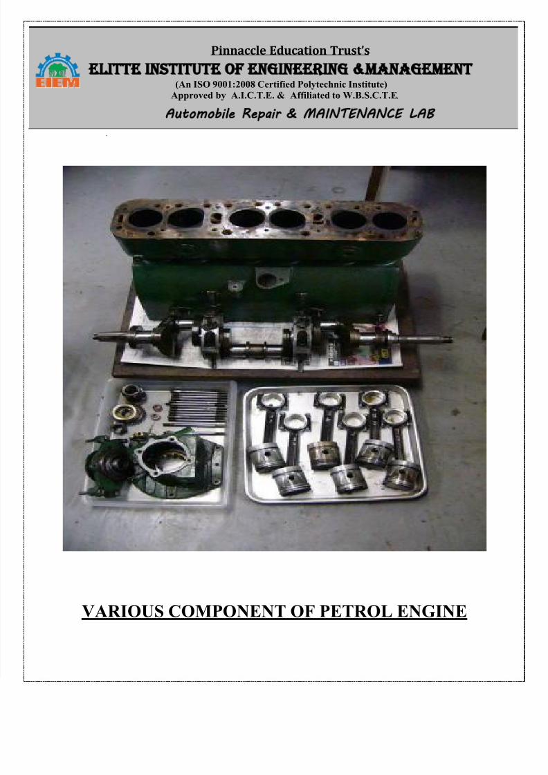
Title of the Experiment: -- Overhauling petrol engine.
Theory : -- The ability of petrol to furnish power rests on the tow basic principles of physics
1)Burning or combustion is always accompanied by the production heat.
2)When a gas is heated, it expand if the volume remains constant, the preesure rises according
to the charles low.
Tools and Equipments: -- 1.Socket set 2.Flat screw driver 3.Valve lifter 4.Torque wrench
5.Filler gauge 6. Ring Spanner set 6. Double ended hammer.
Trainee Material : -- 1. Cotton waste 2. Emary Paper 3. Grinding paste 4. Engine oil 5.Kerosene oil .
Procedure: -- 1. Uncover muffler clamped and screwed it from exhaust manifold.
2. Choke and acceleration connection one removed.3. Removed vaccum pipe installed in between carburetor and distributor.
4. Unthreaded both nuts of carburetor took whole assembly away from intake manifold.5. Pulled out all push rod from cylinder block.
6. Hood gasket was changed.7. Dismantled all valves using valves using valve lifter and checked then properly.
8. All intake and exhaust valve seats was grained.9. Fitted push rod, head gasket on the engine block folled by cylinder head and tighten all nuts.
10. Fitted all the valves to it and locked then cutter.11. Connected petrol pipe to inlet union.
12. Connected high tension load to respective load.
8/13/2019 Repair Maintenance
http://slidepdf.com/reader/full/repair-maintenance 34/34
Pinnaccle Education Trust’s ELITTE INSTITUTE OF ENGINEERING MANAGEMENT
(An ISO 9001:2008 Certified Polytechnic Institute)Approved by A.I.C.T.E. & Affiliated to W.B.S.C.T.E. Automobile Repair MAINTENANCE LAB
VARIOUS COMPONENT OF PETROL ENGINE