Renewal through transformation in Dearborn
5
Ford brings modern district energy to its Research and Engineering Center via DBOOM Mike Walters, PE, Regional Director, MEP Geothermal Engineering Rick Humphries, PE, Manager of Business Development, DTE Energy Services (POSSIBLY OMIT) October 2019 T he last decade has brought im- mense change to the automobile industry. Technological advances in automobile electrification, bat- tery storage, autonomous vehicles and data analytics have profoundly impacted automakers and their business models. Uber, the multinational ridesharing and transportation network is just one of the agents of innovation, having developed its own self-driving cars and various delivery platforms, such as Uber Eats. Recognizing these changes, Ford Motor Co. initiated an evolution to become a mobility company – not purely an automaker. It began implementing operational and facilities changes to support this over the past decade. One physical manifestation of this shift to mobility is the transformation of Ford’s Dearborn, Mich., facilities into a modern, green, and high-tech campus. Changes began in Dearborn in April 2016 at the company’s Research and Engineering Center (REC), which has served as the heart of Ford’s operations since it was dedicated by President Eisenhower in 1953. In planning to modernize the REC, Ford set out to transform its workplaces into inspiring, innovative, and sustain- able environments that support company business objectives. In keeping with project sustainability goals, plans for the redesigned REC include construction of a new central energy plant and distribution system, with completion in December 2019. This project has been developed and is being executed using a design-build-own-op- erate-maintain – or DBOOM – model that offers integrated project delivery, external capital and operational efficien- cies that have been improved over the traditional approach. NEW TECHNOLOGIES AND PROJECT DELIVERY MODELS Coinciding with the upheaval and evolution in the auto industry have been significant shifts within the energy indus- try. Increasing support for environmental sustainability has driven technological innovation in renewables, distributed energy generation, energy storage, con- trols, and approaches to building HVAC design. All of these have coalesced to increase acceptance of the value propo- sition of modern district energy. As laid out in the United Nations Environment Programme’s 2015 District Energy in Cities report, “fourth-genera- tion,” or low-temperature district energy networks are being implemented around the world. Integrating two-way district heating and cooling and using smart energy management and renewable or secondary heat production, such net- works employ the type of infrastructure required of the sustainable environments envisioned for Ford’s transformed REC. These increasingly complex, inte- grated utility systems associated with district energy networks have given rise to alternative project development and operational models. The design- buildown-operate- maintain model has evolved to provide many potential benefits. For example, the DBOOM approach: embeds operational expertise in the design and construction process, reduces operating and maintenance costs by operating utility systems effi- ciently and reliably, Renewal through transformation in Dearborn
Transcript of Renewal through transformation in Dearborn

Ford brings modern district energy to its Research and Engineering Center via DBOOM
Mike Walters, PE, Regional Director, MEP Geothermal EngineeringRick Humphries, PE, Manager of Business Development, DTE Energy Services (POSSIBLY OMIT)
October 2019
T he last decade has brought im-mense change to the automobile industry. Technological advances in automobile electrification, bat-
tery storage, autonomous vehicles and data analytics have profoundly impacted automakers and their business models. Uber, the multinational ridesharing and transportation network is just one of the agents of innovation, having developed its own self-driving cars and various delivery platforms, such as Uber Eats. Recognizing these changes, Ford Motor Co. initiated an evolution to become a mobility company – not purely an automaker. It began implementing operational and facilities changes to support this over the past decade. One physical manifestation of this shift to mobility is the transformation of Ford’s Dearborn, Mich., facilities into a modern, green, and high-tech campus. Changes began in Dearborn in April 2016 at the company’s Research and Engineering Center (REC), which has served as the heart of Ford’s operations since it was dedicated by President Eisenhower in 1953. In planning to modernize the REC, Ford set out to transform its workplaces into inspiring, innovative, and sustain-able environments that support company business objectives. In keeping with project sustainability
goals, plans for the redesigned REC include construction of a new central energy plant and distribution system, with completion in December 2019. This project has been developed and is being executed using a design-build-own-op-erate-maintain – or DBOOM – model that offers integrated project delivery, external capital and operational efficien-cies that have been improved over the traditional approach.
NEW TECHNOLOGIES AND PROJECT DELIVERY MODELS Coinciding with the upheaval and evolution in the auto industry have been significant shifts within the energy indus-try. Increasing support for environmental
sustainability has driven technological innovation in renewables, distributed energy generation, energy storage, con-trols, and approaches to building HVAC design. All of these have coalesced to increase acceptance of the value propo-sition of modern district energy. As laid out in the United Nations Environment Programme’s 2015 District Energy in Cities report, “fourth-genera-tion,” or low-temperature district energy networks are being implemented around the world. Integrating two-way district heating and cooling and using smart energy management and renewable or secondary heat production, such net-works employ the type of infrastructure required of the sustainable environments envisioned for Ford’s transformed REC. These increasingly complex, inte-grated utility systems associated with district energy networks have given rise to alternative project development and operational models. The design-build own-operate- maintain model has evolved to provide many potential benefits. For example, the DBOOM approach: embeds operational expertise in the
design and construction process, reduces operating and maintenance
costs by operating utility systems effi- ciently and reliably,
Renewal through transformation in Dearborn

reduces labor costs, reduces retail power costs through
self-generation or efficiency improve- ments, reduces or eliminates capital spending
on existing infrastructure or deferred maintenance, and improves emissions footprints associ-
ated with utility systems.In the case of Ford’s Research and En-gineering Center, the critical benefits of this model are the preservation of capital availability for facility renewal and, with the role played by the DBOOM supplier, the ability of Ford to focus on its core business activities.
CURRENT REC FACILITIES Ford’s Research and Engineering Center has served as the global re-search and development heart of Ford’s operations for more than 60 years. The campus consists of 6.5 million gross sq ft across 900 acres. It includes an array of facilities from conventional office buildings to laboratory facilities, a large dynamometer building and wind tunnels. The center is bisected by Oakwood Boulevard, which separates the test track and its facilities from most of the research and office buildings. The broad programmatic uses of the center’s facilities create a complex utility demand for conventional HVAC systems and a range of process energy uses to support climate-controlled vehicle testing and laboratory research environments. Historically, REC buildings have stood in-dependently from one another and have been provided utilities via centrally gen-erated steam from the Elm Street Pow-erhouse and grid-purchased electricity.
Much of the campus’s legacy chilled-wa-ter production has been generated from individual, in-building absorption chillers; however, electric centrifugal equipment and low temperature process chillers also provide cooling to some facilities.
TRANSFORMATION SUSTAINABILITY OBJECTIVES Ongoing planning and development at the REC will create a contemporary work environment that can accommodate thousands of additional employees. Early master planning defined a range of high-performance sustainability objectives to accompany the modernization program. From an energy and utilities perspective, these objectives included a 50 percent reduction in carbon dioxide
emissions, 50 percent reduction in water use, 60 percent improvement in chilled
water production efficiency, and 100 percent of space heating provided
from recovered waste heat or geother- mal energy sources. An overarching design goal for the energy system redevelopment was incor-poration of the concept of low entropy – defined in this instance as a campus that minimizes energy waste and maximizes productivity. Two key components sup-porting this concept are development of a new central energy plant and an integrat-ed campus energy infrastructure capable of providing conditioned environments for building occupants using water-based systems as close to room temperature as possible. These strategies will allow the REC to minimize the use of steam for process loads associated with laboratory and testing facilities.
ENERGY MASTER PLANNING Space planning for the complete REC transformation involved a multidisci-plinary team of architects, engineers, planners, contractors and representa-tives from Ford and the company’s real estate development entity, Ford Land. This initial physical space planning was expanded by MEP Geothermal Engi-neering, PLLC (MEPGeo), in the form of an energy master plan for the REC and the schematic design of a central energy plant to serve it. MEPGeo utilized an in-tegrated utility planning framework, which included hourly load models of electric-ity, steam, chilled water, cool water (for potential chilled-beam applications) and hot water. Building energy models were developed for all new buildings, defined by the physical master plan, major renovations, and existing facilities. Model outputs were coordinated with phasing plans for capital improvements and used as the basis for 30-year lifecycle cost as-sessments of central plant utility supply options. As the energy master plan defined the components and scale of the new central energy plant, the process of selecting a DBOOM supplier began. This was an interactive process that started with a request for qualifications issued in May 2016 and wrapped up with final selection in December that same year. Bidders were provided a conceptual design narrative, central energy plant drawings and specifications from which to develop their proposals. Multiple bidder meet-ings were held with short-listed teams throughout 2016 to provide updates on energy planning and campus master
2015
2016
2017
2018
2019
2020
R & E CenterEnergy Master Plan
March 2016 - December 2016
CEP for R & E Center schematic design
July 2016 - November 2016
CEP for R & E Center construction documents
May 2017 - August 2018
CEP for R & E Centerdesign development
December 2016 - April 2017
MEP Selected for R & E Center
Master PlanMarch 2016
Commercial operationof CEP plantJanuary 2020
DBOOMsupplier
procurementJuly 2016 -
December 2016
DBOOM contract negotiations
January 2017 - April 2017
DBOOM RFP issuedAugust 2016
DBOOM final selectionDecember 2016
DBOOMshort list
July 2016
DBOOMRFQ issued
May 2016
DBOOM interviewsDecember 2016
MEP Design Master planDBOOM Construction activities Onsite studies / tests
Construction of West Pond geothermal field
June 2017 - September 2017
Construction of A, B and Cgeothermal fields
March 2019 - November 2019
Commissioning of CEPAugust 2019 - December 2019
Construction of CEPApril 2018 - August 2019
Geothermal test boresOctober 2017
Geothermal thermalconductivity tests
May 2016
DearbornCampus Transformation Master Plan
April 2015 - April 2016
FIGURE 1. Planning, design and construction timeline for the Research and Engineering Center central energy plant project.
planning processes. Refer to figure 1 for a complete project timeline. To accelerate the project schedule, the energy master plan and schematic design of the central energy plant were concurrently finalized in December 2016, as the DBOOM supplier selec-tion progressed and concluded. As such, the energy master plan and plant design were closely coordinated with the selected DBOOM provider: DTE Energy Services - a wholly owned, nonregulated subsidiary of DTE Energy Co., which is a Detroit based energy holding company that also consists of regulated gas and electric utilities, as well as other nonutility businesses. As Ford and DTE Energy Services progressed with contract negotiations, design development of the facility was initiated with DTE Energy Services’ development, engineering, and opera-tions teams. Concurrent work streams for project development (estimating, contract negotiation, equipment supplier bidding, etc.), engineering (central energy plant systems, civil infrastructure) and site logistics brought a large, collaborative team together to maintain the project schedule while integrating construction, operations and maintenance, prefab-rication, and equipment expertise into
the early stages of the project to ensure long-term operational success.
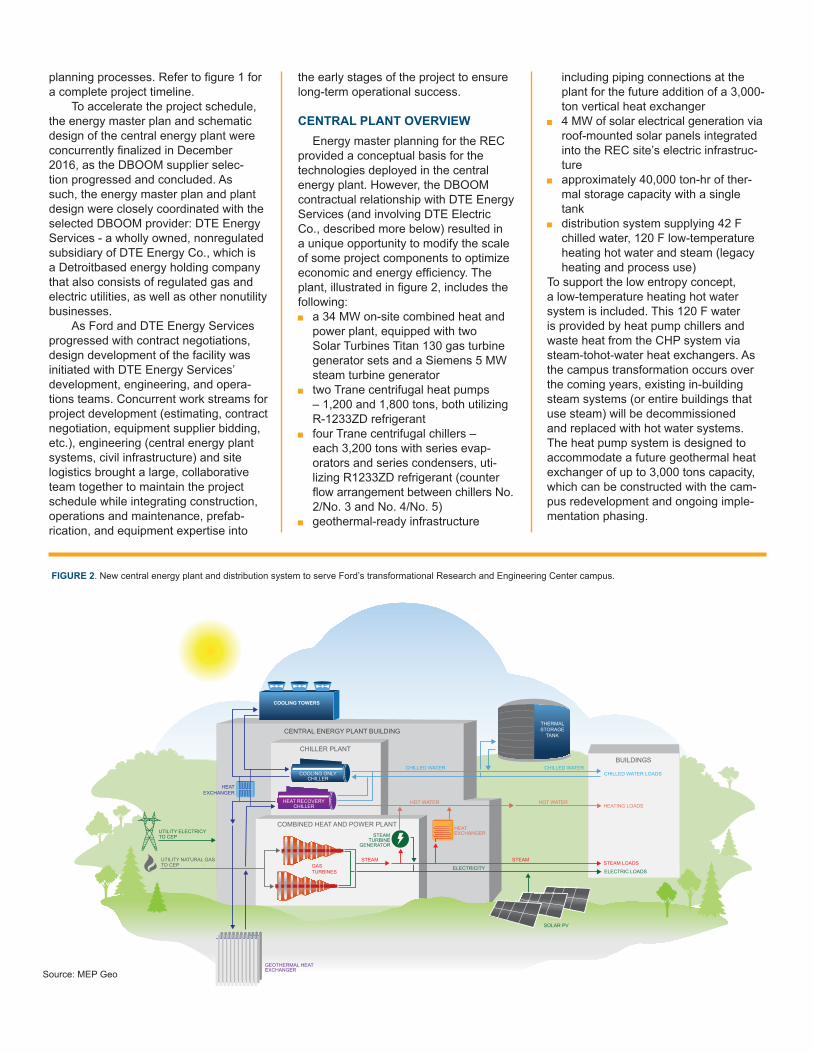
CENTRAL PLANT OVERVIEW Energy master planning for the REC provided a conceptual basis for the technologies deployed in the central energy plant. However, the DBOOM contractual relationship with DTE Energy Services (and involving DTE Electric Co., described more below) resulted in a unique opportunity to modify the scale of some project components to optimize economic and energy efficiency. The plant, illustrated in figure 2, includes the following: a 34 MW on-site combined heat and
power plant, equipped with two Solar Turbines Titan 130 gas turbine generator sets and a Siemens 5 MW steam turbine generator two Trane centrifugal heat pumps
– 1,200 and 1,800 tons, both utilizing R-1233ZD refrigerant four Trane centrifugal chillers –
each 3,200 tons with series evap- orators and series condensers, uti- lizing R1233ZD refrigerant (counter flow arrangement between chillers No. 2/No. 3 and No. 4/No. 5) geothermal-ready infrastructure
including piping connections at the plant for the future addition of a 3,000- ton vertical heat exchanger 4 MW of solar electrical generation via
roof-mounted solar panels integrated into the REC site’s electric infrastruc- ture approximately 40,000 ton-hr of ther-
mal storage capacity with a single tank distribution system supplying 42 F
chilled water, 120 F low-temperature heating hot water and steam (legacy heating and process use)To support the low entropy concept, a low-temperature heating hot water system is included. This 120 F water is provided by heat pump chillers and waste heat from the CHP system via steam-to hot-water heat exchangers. As the campus transformation occurs over the coming years, existing in-building steam systems (or entire buildings that use steam) will be decommissioned and replaced with hot water systems. The heat pump system is designed to accommodate a future geothermal heat exchanger of up to 3,000 tons capacity, which can be constructed with the cam-pus redevelopment and ongoing imple-mentation phasing.
THERMAL STORAGE
TANK
HEAT EXCHANGERSTEAM
TURBINEGENERATOR
STEAM STEAM
HOT WATER HOT WATER
GASTURBINES
CHILLER PLANT
COOLING ONLY CHILLER
HEAT RECOVERY CHILLER
CENTRAL ENERGY PLANT BUILDING
BUILDINGS
COMBINED HEAT AND POWER PLANT
GEOTHERMAL HEATEXCHANGER
UTILITY ELECTRICY TO CEP
UTILITY NATURAL GAS TO CEP
CHILLED WATERCHILLED WATER
ELECTRICITY
CHILLED WATER LOADS
HEATING LOADS
STEAM LOADS
ELECTRIC LOADS
SOLAR PV
HEAT EXCHANGER
COOLING TOWERS
FIGURE 2. New central energy plant and distribution system to serve Ford’s transformational Research and Engineering Center campus.

DBOOM: WHAT IS IT? The DBOOM delivery model seeks to optimize the efficacy of infrastructure investments throughout the lifecycle of a project (30-50 years). The model aims to align risks, expertise (design, con-struction and operation), ownership and performance incentives with the project parties who are best-suited to effectively address them. The DBOOM approach encompasses: Design – design of the project as a
holistic system Build – construction, balancing the
design specification and long-term
operational needs Own – integration of risk through-
out the project’s lifecycle, includ- ing financial, construction and performance risks Operate – optimizing operation for the
benefit of the customer/end user of the utilities Maintain – maintenance and
upgrading of technologies throughout the lifecycle by imple- menting and deploying improvements and additional capital expendituresThe traditional delivery model is com-pared to DBOOM in figure 3. In the case of the REC, a complex
district energy plant was conceived to meet the sustainability objectives of the campus transformation. Recognizing the need for a specialized operator to guar-antee the long-term performance of the facility, Ford chose the DBOOM delivery model for the project. Integrating the operational knowledge of DTE Energy Services and the deep experience of the project’s skilled contractors into the design and construction process ensured long-term operational needs would be met as the design progressed through various approval and costing stages.
DBOOM PROJECT STRUCTURE The typical structure of a DBOOM project involves the creation of a spe-cial purpose vehicle (SPV) as the legal corporate entity. The SPV establishes a variety of contracts with a project opera-tor, design team, contractor, and the customer. In most cases the controlling member (or even sole member) of the SPV will be the project operator, but the SPV may have a wide range of potential participants including financer, operator, contractor, manufacturer, or designer(s). The SPV will typically provide project funding using a combination of project debt and project equity. This typical project structure is customized for each unique project and its requirements and participants. In the case of the Ford REC project, where Ford contracted with DTE Energy Services, the DBOOM structure was simplified as indicated in the diagram in figure 4. The REC project established DTE Dearborn CEP LLC as the SPV for Ford’s DBOOM development. DTE Dearborn CEP LLC was developed as a subsidi-ary of DTE Energy Services. While this initially created a simple contractual structure, the nature of the central energy plant components – specifically the pres-ence of CHP assets – established a de-sire for DTE Electric, the regulated public utility, to also play a role in the project. DTE Electric understood the value of a significant distributed production asset as part of its integrated resource strategy and thus successfully sought to develop the CHP assets within the central energy plant project. The contractual responsi-bilities and boundaries are identified in figure 5.
FORD
PROJECT DESIGNER / CONTRACTORDTE ENERGY SERVICES
PROJECT OPERATORDTE ENERGY SERVICES
MEP ASSOCIATESPEC
WALBRIDGE
SOLARRENTECH
DRESSER-RAND
OTHER WATER TREATMENTSOLAR OTHER
PROJECT SPECIFIC:DTE DEARBORN CEP, LLC
PROJECTFUNDING
DTEENERGY
PROJECT FORMATION......
CUSTOMERREPRESENTATION
Energy services agreement
EPC contract O & M agreement
Equity shareholderagreement
Subcontracts Subcontracts

Through the regulated, public pro-cess, DTE Electric participates in this dis trict energy project by owning the central energy plant assets. DTE Energy Services, an unregulated utility provid-er, maintains ownership of all non-CHP assets, including the campus distribution systems for geothermal energy, chilled water, and hot water. DTE Energy Ser-vices operates the entire plant, including the DTE Electric owned CHP facility. In this manner, signifi cant external capital could be committed to the project, and operability among electrical generation,
the electrical grid and the thermal network could be optimized. The DBOOM development model used for the new central energy plant at Ford’s Research and Engineering Center is an exemplary approach that can be taken for true sustainable infrastructure development. Through Ford’s leadership in the project, a successful pursuit of en-vironmental goals and financial responsi-bility will result in a dramatically improved work environment for the thousands of company employees leading mobility innovation in Dearborn, Mich.
Mike Walters, PE, is the Regional Director of MEP Geothermal En-gineering, PLLC. With a background in energy planning and the design and
construction of geothermal systems and central energy plants, Walters has guided Cornell University’s standard-setting climate action plan, the transformation of Ford Motor Company’s Dearborn Research and Development Center and energy planning and conceptual design for the RiverLInC district energy system in Long Island City. His project roles include project management, engineering leadership, and comprehensive tech-no-economic analysis of energy systems and alternatives.
CHP
CENTRAL ENERGY PLANT
DTEE owns
DTEES builds & operates
DTEES builds, owns & operates
DTEES builds, owns & operates
NON-CHP
GEOTHERMAL
ELECTRICY TO/FROM
DTE ELECTRIC
NATURAL GAS FROM DTE GAS
COMPR.
GAS TURBINES
HEAT PUMP CHILLERS
MECHANICAL CHILLERS
HEAT EXCHANGERS
COOLING TOWER
WATER PUMPS
STEAM TURBINE
HRSG
• 600 acres• 20 buildings• 7.5 million GSF• 30,0000 employees
& DISTRIBUTION
STEAM HEAT
CHILLER WATER
HOT WATER
FORD CAMPUS
FIGURE 5. Contract boundaries for regulated and unregulated utility providers in Ford’s Research and Engineering Center project.
Central Energy Plant piping
Source: MEP Geo