Rendering Gooey Materials with Multiple...
27
Rendering Gooey Materials with Multiple Layers Rendering Gooey Materials with Multiple Layers Chris Oat 3D Application Research Group ATI Research, Inc.
Transcript of Rendering Gooey Materials with Multiple...

1
Rendering Gooey Materials with Multiple Layers
Rendering Gooey Materials with Multiple Layers
Chris Oat3D Application Research GroupATI Research, Inc.

2
OutlineOutline
• Multi-Layered Materials - 30 minutes– Layer compositing
– Depth parallax
– Light diffusion
Making an immersive, compelling virtual environment requires a keen attention to detail. For game programmers, this generally means writing a lot of shaders so that everything has a unique, realistic look. Writing many shaders takes time and in reality rendering performance has to strike a balance with realism. Today I’d like to talk about a rendering technique that uses simple approximations to attain complex looking results. The focus will be on achieving a certain look (realism).
The first topic is multi-layered materials. I will show you a technique that uses multiple texture layers to achieve the look of volumetric surfaces/materials. This technique uses a few simplifying assumptions to reduce rendering cost while maintain that “expensive” look. Several variations will be discussed that allow this technique to scale to your needs based on available GPU resources and compute cycles. I’ll show you how to achieve the look of volume by taking advantage of depth parallax and approximating light diffusion.

3
IntroductionIntroduction
• Rendering semi-transparent, multi-layered materials– Surface with multiple texture layers– Texture layers are blended in some way
• Old way: Multi-texture blending– Lerping two textures looks flat – Layers are squashed together
• New way: Combination of techniques– Normal mapping– Transparency masking– Parallax offset mapping– Image filtering
This technique is appropriate for rendering a certain class of materials, specifically multi-layered, volumetric materials. These materials blend multiple texture layers to create a volumetric look. Historically these surfaces have been rendered using simple multi-texture blending however this doesn’t provide a sufficiently realistic look since simple texture blending results in flat, non-volumetric looking materials. We improve upon the simple multi-texture blending to create realistic looking multi-layer materials by leveraging several well known real time rendering techniques: normal mapping, transparency masking, parallax offset mapping, and image filtering. We combine these technologies to create realistic looking multi-layered materials.

4
MotivationMotivation
• Many real world surfaces have volumetric material properties:– Examples: Biological tissues, cloudy
atmosphere, aliens, etc…
• These materials have a very unique appearance– Don’t look like the kinds of materials we
typically render– Zombie Guts != Plastic Teapots
• Traditionally you might use a volume renderer to achieve this look– Ray tracing isn’t practical for us– Choose the most important visual
components and approximate them!
Being able to render realistic multi-layered materials is important because many real work surfaces have volumetric material properties. Surfaces such as biological tissues, volumetric atmospheric effects, and fictitious materials such as alien skin all exhibit volumetric properties. These materials differ from the kinds of materials we typically render in our games, in particular the get their unique appearance from the complex light interactions that occur between surface layers. The image on the right illustrates a multi-layered shader that’s been applied to a human heart model.
We can’t run a full volume renderer and still hope to be interactive so we have to choose the visual components that are important to us and find inexpensive ways to achieve the right look. Let’s take a look at the more important visual cues that provide a material with the look of “volume.”

5
What are we trying to approximate?What are we trying to approximate?
• Volumetric material– Volume approximated with multiple discrete layers– Layers are semi-transparent– Layers reflect, absorb, and transmit light
• Visually important properties:– Inter-layer occlusion
• Layers store opacity in alpha– Depth parallax
• Parallax due to layer depth or thickness– Light diffusion
• Light scatters between layers
• How can we achieve the look and still be fast?– Alpha blend/composite– Parallax offsetting– Blurring
We seek to approximate the visually complex interaction of multi-layered, semi-transparent surfaces. We don’t necessarily want to implement something that’s physically correct, we just want good fakes for the visually important elements. We want: depth parallax, inter-layer occlusion, light diffusion.
1. Inter-layer occlusion just means that opaque outer regions should correctly occlude inner regions. This is simple to achieve by storing opacity values in the alpha channels of each layer.
2. Depth parallax is simply the perception of perspective due to depth. When you look down into a volume you see the volume from a particular perspective, when you look at more grazing angles you see the volume differently. You don’t get this will plain old fixed function multi-texture blending. More on this in later slides.
3. Light diffusion is the scattering of light as it passes through surfaces layers. Lighting is such an important visual cue that it’s necessary to provide some form of approximation here so that the user gets the impression of layer depth and translucency.
We achieve this look by cheating! We use alpha blending tricks, parallax offsetting, and image filtering to get volumetric looking materials.
6
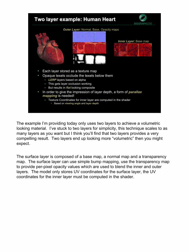
Two layer example: Human HeartTwo layer example: Human Heart
• Each layer stored as a texture map• Opaque texels occlude the texels below them
– LERP layers based on alpha– This gets layer occlusion working– But results in flat looking composite
• In order to give the impression of layer depth, a form of parallaxmapping is needed!– Texture Coordinates for inner layer are computed in the shader
• Based on viewing angle and layer depth
Outer Layer: Normal, Base, Opacity maps
Inner Layer: Base map
The example I’m providing today only uses two layers to achieve a volumetric looking material. I’ve stuck to two layers for simplicity, this technique scales to as many layers as you want but I think you’ll find that two layers provides a very compelling result. Two layers end up looking more “volumetric” then you might expect.
The surface layer is composed of a base map, a normal map and a transparency map. The surface layer can use simple bump mapping, use the transparency map to provide per-pixel opacity values which are used to blend the inner and outerlayers. The model only stores UV coordinates for the surface layer, the UV coordinates for the inner layer must be computed in the shader.

7
Multi-layer depth parallaxMulti-layer depth parallax
• Make the material look volumetric
• Depth parallax– Shift in apparent position due to change in view
– Inner layer shifts with respect to outer layer
– Shift is more pronounced as depth increases
• Can’t use surface layer’s UV coordinate to sample inner layer’s texture
Eye
Subsurface layers should exhibit parallax to give the impression of depth.
Parallax is the apparent shift in position due to a change in the viewer’s line of sight.
By exploiting the effects of parallax in our shader we can add a sense of depth to the surface layers; this proves to be a very important visual cue that will allow us to achieve more realistic looking layered surfaces.

8
Multi-layer depth parallaxMulti-layer depth parallax
Eye
• Make the material look volumetric
• Depth parallax– Shift in apparent position due to change in view
– Inner layer shifts with respect to outer layer
– Shift is more pronounced as depth increases
• Can’t use surface layer’s UV coordinate to sample inner layer’s texture
In addition to appearing blurry, subsurface layers should exhibit parallax. Parallax is the apparent shift in position due to a change in the viewer’s line of sight. Figure illustrates two different viewpoints of the same surface. If simple, multi-texture blending was used to render this surface, as the viewpoint changed the under layer would remain fixed relative to the top layer and this would result in the various surface layers appearing flat or squashed. By exploiting the effects of parallax in our shader we can add a sense of depth to the surface layers; this proves to be a very important visual cue that will allow us to achieve more realistic looking layered surfaces.

9
Multi-layer depth parallaxMulti-layer depth parallax
Eye
• Make the material look volumetric
• Depth parallax– Shift in apparent position due to change in view
– Inner layer shifts with respect to outer layer
– Shift is more pronounced as depth increases
• Can’t use surface layer’s UV coordinate to sample inner layer’s texture
In addition to appearing blurry, subsurface layers should exhibit parallax. Parallax is the apparent shift in position due to a change in the viewer’s line of sight. Figure illustrates two different viewpoints of the same surface. If simple, multi-texture blending was used to render this surface, as the viewpoint changed the under layer would remain fixed relative to the top layer and this would result in the various surface layers appearing flat or squashed. By exploiting the effects of parallax in our shader we can add a sense of depth to the surface layers; this proves to be a very important visual cue that will allow us to achieve more realistic looking layered surfaces.

10
Inner layer’s texture coordinatesInner layer’s texture coordinates
• Layers are assumed to be parallel in tangent space– Layer depth d is homogeneous for a given layer
• Find inner layer’s texture coordinate1. Find view vector = V2. Reflect V about Normal (from normal map) = R3. Reflect R about surface plane = transmission vector T
• In tangent space, we simply negate R.z component4. Find distance s along T to inner layer: Function of distance d between layers5. Use T and s this to find inner layer’s texture coordinate
⟩⟨+⟩⟨=⟩⟨
=
⟩−⟨=
−−−=
yx
z
zyx
TTsvuvu
Tds
RRRTNNVdotVR
vv
v
vvvv
vvvvv
,,','
/
,,*),(*2
= Outer UV coordinate: <u,v>= Inner UV coordinate: <u’,v’>
V
d
NR
sT
In order to calculate the inner layer’s texture coordinate we must first calculate a transmission vector. The transmission vector points from the outer surface layer’s sample point to the inner surface layer’s sample point (as shown in diagram). The offset texture coordinate is determined by finding the intersection of the transmission vector with the inner layer.
We save ourselves a bunch of ray/intersection testing by assuming that the layers are flat and parallel in tangent space.
We use a very simple approximation to calculate the transmission vector; the tangent space view vector is reflected about the per-pixel normal (sampled from a normal map) to find a reflection vector. The reflection vector is then reflected about the surface plane such that it points into the surface. Because these vectors are in tangent space, reflecting the reflection vector about the surface plane is simply a matter of negating its z component. We now have a unit length transmission vector. Next we find the length along the transmission vector to the inner layer by dividing the layer thickness by the absolute value of the transmission vector’s z component. This length, along with the transmission vector’s x and y components give us a UV offset for sampling from the inner layer’s base map.

11
Parallax offsetParallax offset
// Compute inner layer’s texture coordinate and transmission depth// vTexCoord: Outer layer’s texture coordinate// vViewTS: View vector in tangent space// vNormalTS: Normal in tangent space (sampled normal map)// fLayerThickness: Distance from outer layer to inner layerfloat3 ParallaxOffsetAndDepth ( float2 vTexCoord, float3 vViewTS,
float3 vNormalTS, float fLayerThickness ){
// Tangent space reflection vectorfloat3 vReflectionTS = reflect( -vViewTS, vNormalTS );
// Tangent space transmission vector (reflect about surface plane)float3 vTransTS = float3( vReflectionTS.xy, -vReflectionTS.z );
// Distance along transmission vector to intersect inner layerfloat fTransDist = fLayerThickness / abs(vTransTS.z);
// Texel size: Hard coded for 1024x1024 texture sizefloat2 vTexelSize = float2( 1.0/1024.0, 1.0/1024.0 );
// Inner layer’s texture coordinate due to parallaxfloat2 vOffset = vTexelSize * fTransDist * vTransTS.xy;float2 vOffsetTexCoord = vTexCoord + vOffset;
// Return offset texture coordinate in xy and transmission dist in zreturn float3( vOffsetTexCoord, fTransDist );
}
1. Reflect tangent space view vector about the per-pixel normal from the normal map using HLSL intrinsic reflect function
2. Find a tangent space transmission vector by negating the z component of the tangent space reflection vector
3. Find the distance along transmission vector to the next layer by dividing the layer thickness by the absolute value of the transmission vector’s z component
4. Find the UV offset in texel units (assuming a 1024x1024 texture here)5. Use the offset to find a new UV coordinate for the inner layer6. Return the new UV coordinate and the transmission distance
The new UV coordinate is then used for sampling the inner layers base map.

12
Parallax creates the illusion of depthParallax creates the illusion of depth
• The offset texture coordinate is used for sampling from the inner layer’s texture
• This creates the illusion of depth or volume even though the surface geometry is flat
• We still need a way to light the inner layer convincingly…
Eye

13
Multi-layer light diffusionMulti-layer light diffusion
• Light scatters as it enters a material1. Light reaches surface2. Some reflects back to eye3. Some scatters further into the material4. GOTO 2
• Physically based models for scattering are slow• Get the look without doing the math!
– Light reflected back to eye from surface– Light scatters on its way in– Light scatters on its way out
Eye
A material’s reflectance properties provide important visual cues about the material. In order to achieve a volumetric look, we need to approximate the effects of light diffusing as it passes through a volumetric material.
The deeper a given ray travels into a surface, the more opportunities there are for scattering. Light is scatters as it enters the material. Some light is reflected back towards the viewer, some light is scattered further into the material. Light that scatters into the material will have further opportunities to be scattered back to the viewer or deeper into the material. The perceivable result of this scattering is subsurface layers appearing blurry relative to the top most surface layers. The deeper the layer from the surface, the more blurry it appears. Deeper layers also appear more evenly lit since they have light scattered onto them from many directions.

14
Getting the look: Incoming light Getting the look: Incoming light
• Surface layer lit as usual (N.L)– Accounts for light that doesn’t enter material
• Inner layer is more evenly lit– Transmitted light scatters onto layer from many directions
• Texture space lighting– Render diffuse lighting into an off-screen texture using texture
coordinates as positions– Acts like a dynamic light map for the outer layer
We know how to hand the directly reflected light, the light that is directly scattered back into the eye. This accounts for all the light that reflects off the outer layer and directly back to the viewer.
In order to get a correct lighting term for the inner layer, we need to account for some of the incoming scattering as light passes through the material. Instead of having this highly directional lighting component for the inner layer, we need a method that will provide a more even lit surface to account for all the scattering that’s happening as light enters the material.
You can achieve this by using a technique known as texture space lighting. Essentially you render a dynamic diffuse light map into an offscreen renderabletexture map.

15
Getting the look: Incoming lightGetting the look: Incoming light
• Texture space lighting– Render diffuse lighting into an off-screen texture– Light as a 3D model but draw into texture– Vertex shader outputs texture coordinates as projected “positions” then
the rasterizer does the unwrap– Vertex shader computes light vectors based on 3D position and
interpolates– This is a light map for the outer layer– HLSL implementation online: Dave Gosselin’s Skin Rendering Slides
• www.ati.com/developer/gdc/D3DTutorial_Skin_Rendering.pdf
More complex lighting is possible through dynamic light mapping. Many developers use a dynamic diffuse light map for approximating subsurface scattering in skin. You render the object in texture space (light map space) then blur the light map then apply it to the final object. You could do something like this: Render surface layer in light map space, blur it and use this for per-pixel incoming light for the next layer down. Each inner layer uses the blurred light map of the previous layer as an “incoming light” term and thus the light is propagated down to lower layers, becoming progressively more blurry (this also allows upper layers to cast shadows into lower layers).

16
Getting the look: Incoming lightGetting the look: Incoming light
• For the inner layer’s lighting, use a blurred version of the outer layer’s light map
• This gives us smooth, diffused lighting on the inner layer
• The amount of blurring depends on the thickness of the outer layer
– Use a variable sized blur kernel
Outer layer’s light maps
Inner layer

17
Poisson disc kernelPoisson disc kernel
• A Poisson disc kernel is ideal since it can be resized dynamically based on the amount of light diffusion you want
• Kernel takes a fixed number of taps from source texture• Taps are distributed randomly on a unit disc (Poisson
distribution)• Disc size can be scaled on a per-pixel basis for more or less
blurring• Our disc’s radius is based on layer thickness
– Thicker layer results in more blurring
Small Blur Area Large Blur Area

18
Growable Poisson discGrowable Poisson disc
// Growable Poisson disc (13 samples)// tSource: Source texture sampler// vTexCoord: Texture space location of disc’s center// fRadius: Radius if kernel (in texel units)float3 PoissonFilter ( sampler tSource, float2 vTexCoord, float fRadius ){
// Hard coded texel size: Assumes 1024x1024 source texturefloat2 vTexelSize = float2( 1.0/1024.0, 1.0/1024.0 );
// Tap locations for unit discfloat2 vTaps[12] = {float2(-0.326212,-0.40581),float2(-0.840144,-0.07358),
float2(-0.695914,0.457137),float2(-0.203345,0.620716),float2(0.96234,-0.194983),float2(0.473434,-0.480026),float2(0.519456,0.767022),float2(0.185461,-0.893124),float2(0.507431,0.064425),float2(0.89642,0.412458),float2(-0.32194,-0.932615),float2(-0.791559,-0.59771)};
// Take a sample at the disc’s centerfloat3 cSampleAccum = tex2D( tSource, vTexCoord );
// Take 12 samples in discfor ( int nTapIndex = 0; nTapIndex < 12; nTapIndex++ ){
// Compute new texture coord inside discfloat2 vTapCoord = vTexCoord + vTexelSize * vTaps[nTapIndex] * fRadius;
// Accumulate samplescSampleAccum += tex2D( tSource, vTapCoord );
}
return cSampleAccum / 13.0; // Return average}

19
Getting the look: Outgoing lightingGetting the look: Outgoing lighting
• The blurred light map approximates light scattering as it enters the material
• Light also scatter as on its way back out of the material• This has the effect of the Inner layer’s base map appearing blurry• Use Growable Poisson Disc filter for sampling inner layer’s base map
– This time kernel size depends on transmission distance through material– Not just layer thickness– Kernel is centered around the inner layer’s parallax offset texture coordinate
• Inner layer now looks blurry– The more material you’re looking through, the blurrier it will look
Eye
Eye

20
Putting it all togetherPutting it all together
// Sample from outer layer’s base map and light map texturesfloat3 cOuterDiffuse = tex2D(tLightMap, i.vTexCoord);float4 cOuterBase = tex2D(tOuterBaseMap, i.vTexCoord); // Opacity in alpha channel
// Compute parallax offset texture coordinate for sampling from inner layer textures// returns UV coord in X and Y and transmission distance in Zfloat3 vOffsetAndDepth = ParallaxOffsetAndDepth(i.vTexCoord, vViewTS,
vNormalTS, fLayerThicknes);
// Poisson disc filtering: blurry light map (blur size based on layer thickness)float3 cInnerDiffuse = PoissonFilter(tLightMap, vOffsetAndDepth.xy, fLayerThickness);
// Poisson disc filtering: blurry base map (blur size based on transmission distance)float3 cInnerBase = PoissonFilter(tInnerBaseMap, vOffsetAndDepth.xy, vOffsetAndDepth.z);
// Compute N.V for additional compositing factor (prefer outer layer at grazing angles)float fNdotV = saturate( dot(vNormalTS, vViewTS) );
// Lerp based on opacity and N.V (N.V prevents artifacts when view is very edge on)float3 cOut = lerp(cOuterBase.rgb*cOuterDiffuse.rgb,
cInnerBase.rgb*cInnerDiffuse.rgb, cOuterBase.a * fNdotV);

21
Demo: Beating human heartDemo: Beating human heart

22
Taking it to the next levelTaking it to the next level
• Increase complexity– More than two layers– Use the same techniques I’ve shown here– This is more expensive, but looks really good!
• Improve quality– Inter-layer shadowing– Scale light map samples by their corresponding opacities from base map– Keeps light from passing through opaque regions– In practice this doesn’t make a huge difference, as you can’t see what’s below an
opaque region unless you’re looking at it very edge on on– More important when you’re using many layers or a very deep/thick material
• Improve performance– Eliminate the off screen render targets– Two suggestions for eliminating renderable texture (light map) – See next slide…

23
Lighting optimization 1Lighting optimization 1
• Outer layer lit as usual– Use a normal map for high frequency surface detail
• Instead of using a blurred light map for the Inner layer’s lighting– Use a modified Poisson Disc filter kernel
– Take multiple samples from outer layer’s Normal Map• Compute N.L for each sample• Average all the N.L computations
• Eliminates the need for a renderable texture!
Eliminates renderable texture. Improve batching by removing that intermediate render step. But this adds a bunch of additional texture sampling.

24
Lighting optimization 2Lighting optimization 2
• Outer layer lit as usual– Use a normal map for high frequency surface detail
• Instead of using a blurred light map or multiple normal map samples for the Inner layer’s lighting:
– Use the geometric normal for computing N.L– Smoother, lower frequency lighting– In practice, this works quite well and it’s a lot faster
• Eliminates the need for a renderable texture!
• Reduces texture bandwidth requirements by eliminating one of the Poisson disc filtering steps
N.L
N.L

25
ConclusionConclusion
• A method for rendering multi-layered materials
• Computationally efficient:– Forget about being physically correct
– Focus on approximating the right “look”• Exploit perceptual cues:
– Depth parallax for volume
– Texture blurring for subsurface scattering

26
ReferencesReferences
• Borshukov, G., and Lewis, J. P. 2003. Realistic Human Face Rendering for The Matrix Reloaded. In the proceedings of SIGGRAPH 2003, Technical Sketches
• Gosselin, D. 2004. Real Time Skin Rendering. Game Developer Conference, D3D Tutorial 9
• Kaneko, T., Takahei, T., Inami, M., Kawakami, N., Yanagida, Y., Maeda, T., Tachi, S. 2001. Detailed Shape Representation with Parallax Mapping. In Proceedings of ICAT 2001, pp. 205-208.
• Sander, P.V., Gosselin, D., and Mitchell, J. L.2004. Real-Time Skin Rendering on Graphics Hardware. In the proceedings of SIGGRAPH 2004, Technical Sketch.
• Welsh, T. 2004. Parallax Mapping, ShaderX3: Advanced Rendering with DirectX and OpenGL, Engel, W. Ed., A.K. Peters, 2004

27
Questions?Chris Oat
These slides are available for download:
www.ati.com/developer