REMOVING SOCKET/PIN TERMINALS INSTALLING ...mael.rivoal.free.fr/Manuel Buell XB9R/sm_appb1.pdf2004...
23
2004 Buell Firebolt: Appendix B B-1 HOME AMP MULTILOCK ELECTRICAL CONNECTORS B.1 REMOVING SOCKET/PIN TERMINALS 1. Remove connector from the retaining device, either attachment or rosebud clip. 2. Depress the button on the socket terminal side of the connector (plug) and pull apart the pin and socket halves. 3. Bend back the latch slightly and free one side of second- ary lock, then repeat the step to release the other side. Rotate the secondary lock outward on hinge to access terminals in chambers of connector housing. 4. Looking in the terminal side of the connector (opposite the secondary lock), take note of the cavity next to each terminal. 5. See Figure B-1. With the flat edge against the terminal, insert the pick tool (Snap-On TT600-3) into the cavity until it stops. Pivot the end of the pick away from the ter- minal (locktab is inside housing) and gently tug on wire to pull terminal from chamber. Do not tug on the wire until the tang is released or the terminal will be difficult to remove. A “click” is heard if the tang is engaged but then inadvertently released. Repeat the step without releasing the tang. NOTES ● If pick tool is not available, a push pin/safety pin may be used instead. ● An ELECTRICAL TERMINAL CRIMP TOOL (Part No. HD-41609) is used to install Amp Multi lock pin and socket terminals on wires. If new terminals must be installed, see Crimping Instructions on the next page. INSTALLING SOCKET/PIN TERMINALS NOTE For wire location purposes, numbers are stamped into the secondary locks of both the socket and pin housings. See Figure B-2. 1. From the secondary lock side of the connector, insert the terminal into its respective numbered chamber until it snaps in place. For proper fit, the slot in the terminal must face the tang in the chamber. Figure B-1. 10-Place Amp Multilock Connector d0242x3x Secondary lock open Secondary lock open Pin housing Pin terminal Socket housing Secondary lock open Socket terminal Button Latch Latch
Transcript of REMOVING SOCKET/PIN TERMINALS INSTALLING ...mael.rivoal.free.fr/Manuel Buell XB9R/sm_appb1.pdf2004...
2004 Buell Firebolt: Appendix B B-1
HOME
73
AMP MULTILOCK ELECTRICAL CONNECTORS B.1
REMOVING SOCKET/PIN
TERMINALS
1. Remove connector from the retaining device, eitherattachment or rosebud clip.
2. Depress the button on the socket terminal side of theconnector (plug) and pull apart the pin and sockethalves.
3. Bend back the latch slightly and free one side of second-ary lock, then repeat the step to release the other side.Rotate the secondary lock outward on hinge to accessterminals in chambers of connector housing.
4. Looking in the terminal side of the connector (oppositethe secondary lock), take note of the cavity next to eachterminal.
5. See Figure B-1. With the flat edge against the terminal,insert the pick tool (Snap-On TT600-3) into the cavityuntil it stops. Pivot the end of the pick away from the ter-minal (locktab is inside housing) and gently tug on wire topull terminal from chamber. Do not tug on the wire untilthe tang is released or the terminal will be difficult toremove. A “click” is heard if the tang is engaged but then
inadvertently released. Repeat the step without releasingthe tang.
NOTES
●
If pick tool is not available, a push pin/safety pin may beused instead.
●
An ELECTRICAL TERMINAL CRIMP TOOL (Part No.HD-41609) is used to install Amp Multi lock pin andsocket terminals on wires. If new terminals must beinstalled, see Crimping Instructions on the next page.
INSTALLING SOCKET/PIN
TERMINALS
NOTEFor wire location purposes, numbers are stamped into thesecondary locks of both the socket and pin housings. SeeFigure B-2.
1. From the secondary lock side of the connector, insert theterminal into its respective numbered chamber until itsnaps in place. For proper fit, the slot in the terminalmust face the tang in the chamber.
Figure B-1. 10-Place Amp Multilock Connector
d0242x3x
Secondary lock open
Secondary lock open
Pin housing
Latch
Pin terminal
Socket housing
Secondary lock open
Socket terminal
Button
Latch
Latch
B-2 2004 Buell Firebolt: Appendix B
HOME
NOTES
●
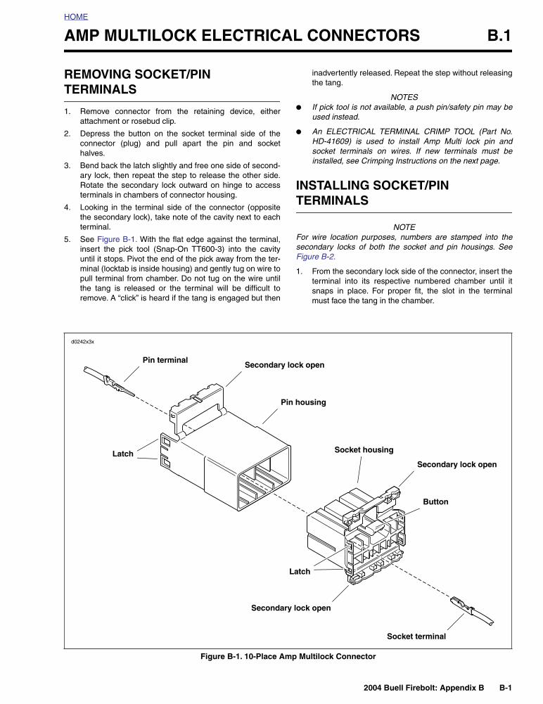
See Figure B-3. The tang in the chamber engages theslot to lock the terminal in position.
●
On the pin side of the connector, tangs are positioned atthe bottom of each chamber, so the slot in the pin termi-nal (on the side opposite the crimp tails) must face down-ward.
●
On the socket side, tangs are at the top of each chamber,so the socket terminal slot (on the same side as thecrimp tails) must face upward.
●
Up and down can be determined by the position of therelease button (used to separate the pin and sockethalves). Consider the button to always be on top of theconnector.
2. Gently tug on wire end to verify that the terminal islocked in place and will not back out of chamber.
3. Rotate the hinged secondary lock inward until tabs fullyengage latches on both sides of connector.
4. Insert the socket housing (plug) into the pin housing(receptacle) until it snaps in place.
5. Install connector on retaining device, either attachmentor rosebud clip.
Figure B-2. Release Tang and Back Out Terminals
2
1
3
4
4
1
2
3
Pin terminal
Socket terminal
Secondary lock open
Secondary lock open
Pick tool
Pick tool
Pin housing
Socket housing
1. Open secondary lock.2. Insert pick into cavity on inboard side
of connector.3. Pivot end of pick to release tang.4. Gently tug on wire to remove terminal
from housing.
d0243x8x
Figure B-3. Multilock Connector Cutaway View
Pin housing
Tang
Socket housing
Tang
d0244x8x
Button
2004 Buell Firebolt: Appendix B B-3
HOME
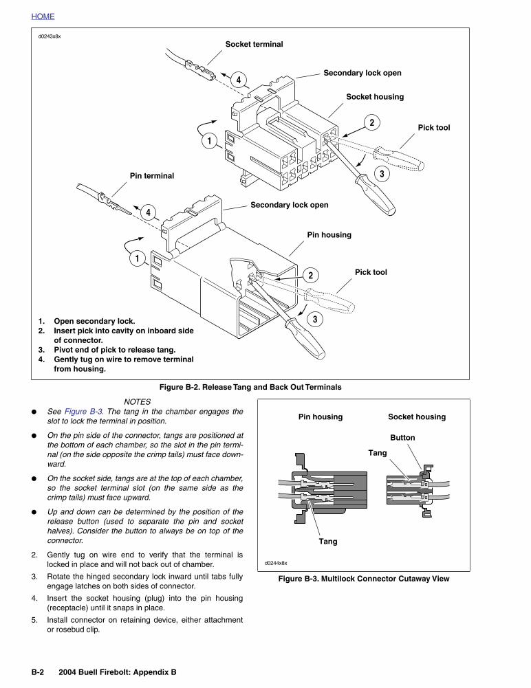
Figure B-4. 3-Place and 6-Place Amp Multilock Connectors
– AMP
1 2 3– AMP
1 2 3 4 5 6 5 6 7 8 9 10
4321
Socket terminal
Secondary lock
Socket housing
Pin housing
Pin terminal
Latch
Secondary lock
Button
Latch
Socket terminal
Secondary lock
Button
Socket housing
Pin housing
Secondary lock
Pin terminal
3-place 6-place 12-place
Secondary locks open (socket housings shown)
Stamped numbers on secondary locks indicate wire color locations
d0245x2x
B-4 2004 Buell Firebolt: Appendix B
HOME
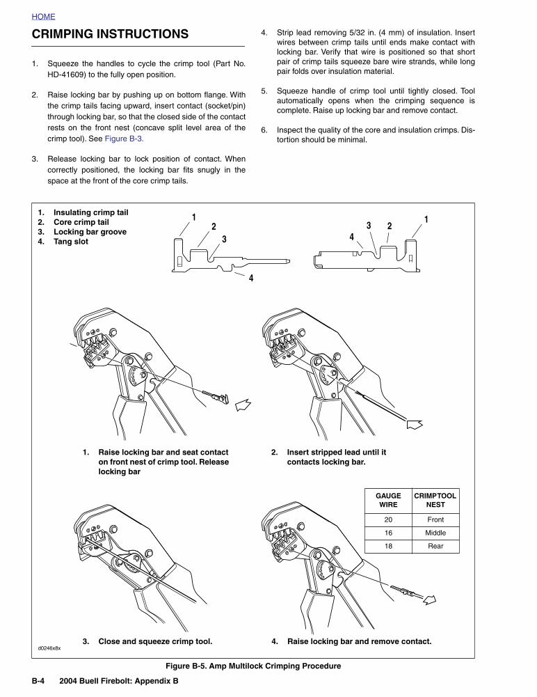
CRIMPING INSTRUCTIONS
1. Squeeze the handles to cycle the crimp tool (Part No.HD-41609) to the fully open position.
2. Raise locking bar by pushing up on bottom flange. Withthe crimp tails facing upward, insert contact (socket/pin)through locking bar, so that the closed side of the contactrests on the front nest (concave split level area of thecrimp tool). See Figure B-3.
3. Release locking bar to lock position of contact. Whencorrectly positioned, the locking bar fits snugly in thespace at the front of the core crimp tails.
4. Strip lead removing 5/32 in. (4 mm) of insulation. Insertwires between crimp tails until ends make contact withlocking bar. Verify that wire is positioned so that shortpair of crimp tails squeeze bare wire strands, while longpair folds over insulation material.
5. Squeeze handle of crimp tool until tightly closed. Toolautomatically opens when the crimping sequence iscomplete. Raise up locking bar and remove contact.
6. Inspect the quality of the core and insulation crimps. Dis-tortion should be minimal.
Figure B-5. Amp Multilock Crimping Procedure
1. Raise locking bar and seat contact on front nest of crimp tool. Release locking bar
2. Insert stripped lead until it contacts locking bar.
3. Close and squeeze crimp tool. 4. Raise locking bar and remove contact.
1. Insulating crimp tail2. Core crimp tail3. Locking bar groove4. Tang slot
21
3
4
43
12
d0246x8x
GAUGE WIRE
CRIMP TOOL NEST
20 Front
16 Middle
18 Rear
2004 Buell Firebolt: Appendix B B-5
HOME
DEUTSCH ELECTRICAL CONNECTORS B.2
GENERAL
Deutsch Connectors feature a superior seal to protect electri-cal contacts from dirt and moisture in harsh environments.The connector also provides superior pin retention.
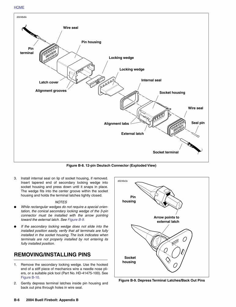
See Figure B-8. This 12-pin connector illustrates the variousparts of the Deutsch connector. The following instructionsmay be followed for all 2-pin through 12-pin Deutsch connec-tors.
Socket housing:
alignment tabs and/or external latch, sec-ondary locking wedge, internal seal, wire seal, seal pin.
NOTE
Seal pins or plugs are installed in the wire seals of unused pinand socket locations. If removed, seal pins must be replacedto maintain the integrity of the environmental seal.
Pin housing:
alignment grooves and/or external latch cover,attachment clip, secondary locking wedge, wire seal, seal pin.
REMOVING/DISASSEMBLING
Attachment clips are attached to the pin housings of mostconnectors. The clips are then attached to T-studs on themotorcycle frame. T-studs give positive location to electricalconnectors and wire harness. Consistent location reduceselectrical problems and improves serviceability.
1. Push the connector to disengage small end of slot onattachment clip from T-stud. Lift connector off T-stud.
2. Depress the external latch(es) on the socket housingside and use a rocking motion to separate the pin andsocket halves. Two-, three-, four- and six-pin Deutschconnectors have one external latch, while eight- andtwelve-pin connectors have two, both of which must bepressed simultaneously to separate the connectorhalves.
NOTE
With few exceptions, the socket housing can always be foundon the accessory side, while the pin side of the connector isconnected to the wiring harness.
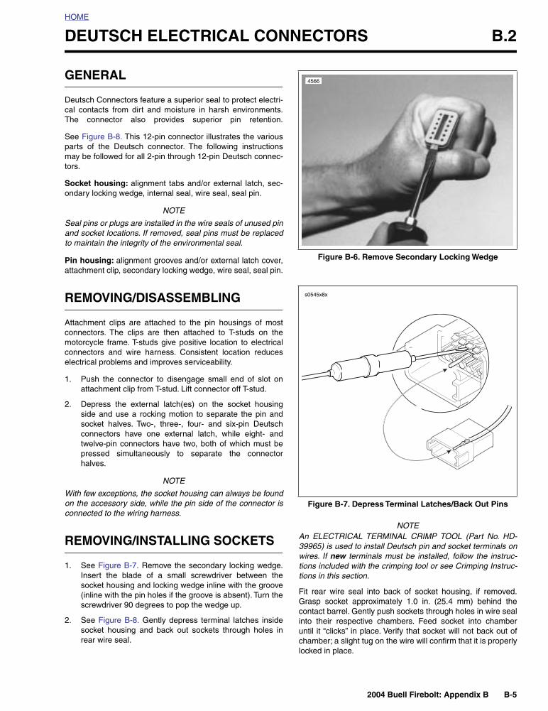
REMOVING/INSTALLING SOCKETS
1. See Figure B-7. Remove the secondary locking wedge.Insert the blade of a small screwdriver between thesocket housing and locking wedge inline with the groove(inline with the pin holes if the groove is absent). Turn thescrewdriver 90 degrees to pop the wedge up.
2. See Figure B-8. Gently depress terminal latches insidesocket housing and back out sockets through holes inrear wire seal.
NOTEAn ELECTRICAL TERMINAL CRIMP TOOL (Part No. HD-39965) is used to install Deutsch pin and socket terminals onwires. If
new
terminals must be installed, follow the instruc-tions included with the crimping tool or see Crimping Instruc-tions in this section.
Fit rear wire seal into back of socket housing, if removed.Grasp socket approximately 1.0 in. (25.4 mm) behind thecontact barrel. Gently push sockets through holes in wire sealinto their respective chambers. Feed socket into chamberuntil it “clicks” in place. Verify that socket will not back out ofchamber; a slight tug on the wire will confirm that it is properlylocked in place.
Figure B-6. Remove Secondary Locking Wedge
Figure B-7. Depress Terminal Latches/Back Out Pins
4566
s0545x8x
B-6 2004 Buell Firebolt: Appendix B
HOME
3. Install internal seal on lip of socket housing, if removed.Insert tapered end of secondary locking wedge intosocket housing and press down until it snaps in place.The wedge fits into the center groove within the sockethousing and holds the terminal latches tightly closed.
NOTES
●
While rectangular wedges do not require a special orien-tation, the conical secondary locking wedge of the 3-pinconnector must be installed with the arrow pointingtoward the external latch. See Figure B-9.
●
If the secondary locking wedge does not slide into theinstalled position easily, verify that all terminals are fullyinstalled in the socket housing. The lock indicates whenterminals are not properly installed by not entering itsfully installed position.
REMOVING/INSTALLING PINS
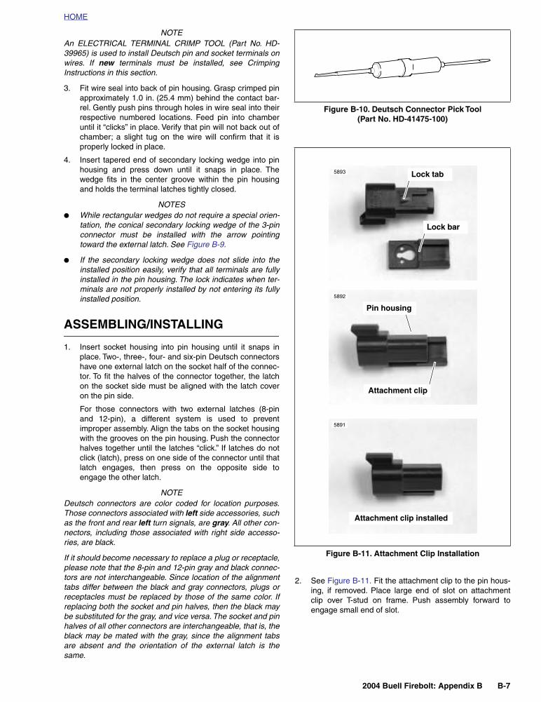
1. Remove the secondary locking wedge. Use the hookedend of a stiff piece of mechanics wire a needle nose pli-ers, or a suitable pick tool (Part No. HD-41475-100). SeeFigure B-10.
2. Gently depress terminal latches inside pin housing andback out pins through holes in wire seal.
Figure B-8. 12-pin Deutsch Connector (Exploded View)
Wire seal
Pin housing
Locking wedge
Locking wedge
Internal seal
Socket housing
Wire seal
Socket terminal
Seal pin
External latch
Alignment tabs
Alignment grooves
Pinterminal
Latch cover
d0248x8x
Figure B-9. Depress Terminal Latches/Back Out Pins
Pinhousing
Sockethousing
Arrow points toexternal latch
d0249x3x
2004 Buell Firebolt: Appendix B B-7
HOME
NOTEAn ELECTRICAL TERMINAL CRIMP TOOL (Part No. HD-39965) is used to install Deutsch pin and socket terminals onwires. If
new
terminals must be installed, see CrimpingInstructions in this section.
3. Fit wire seal into back of pin housing. Grasp crimped pinapproximately 1.0 in. (25.4 mm) behind the contact bar-rel. Gently push pins through holes in wire seal into theirrespective numbered locations. Feed pin into chamberuntil it “clicks” in place. Verify that pin will not back out ofchamber; a slight tug on the wire will confirm that it isproperly locked in place.
4. Insert tapered end of secondary locking wedge into pinhousing and press down until it snaps in place. Thewedge fits in the center groove within the pin housingand holds the terminal latches tightly closed.
NOTES
●
While rectangular wedges do not require a special orien-tation, the conical secondary locking wedge of the 3-pinconnector must be installed with the arrow pointingtoward the external latch. See Figure B-9.
●
If the secondary locking wedge does not slide into theinstalled position easily, verify that all terminals are fullyinstalled in the pin housing. The lock indicates when ter-minals are not properly installed by not entering its fullyinstalled position.
ASSEMBLING/INSTALLING
1. Insert socket housing into pin housing until it snaps inplace. Two-, three-, four- and six-pin Deutsch connectorshave one external latch on the socket half of the connec-tor. To fit the halves of the connector together, the latchon the socket side must be aligned with the latch coveron the pin side.
For those connectors with two external latches (8-pinand 12-pin), a different system is used to preventimproper assembly. Align the tabs on the socket housingwith the grooves on the pin housing. Push the connectorhalves together until the latches “click.” If latches do notclick (latch), press on one side of the connector until thatlatch engages, then press on the opposite side toengage the other latch.
NOTEDeutsch connectors are color coded for location purposes.Those connectors associated with
left
side accessories, suchas the front and rear
left
turn signals, are
gray
. All other con-nectors, including those associated with right side accesso-ries, are black.
If it should become necessary to replace a plug or receptacle,please note that the 8-pin and 12-pin gray and black connec-tors are not interchangeable. Since location of the alignmenttabs differ between the black and gray connectors, plugs orreceptacles must be replaced by those of the same color. Ifreplacing both the socket and pin halves, then the black maybe substituted for the gray, and vice versa. The socket and pinhalves of all other connectors are interchangeable, that is, theblack may be mated with the gray, since the alignment tabsare absent and the orientation of the external latch is thesame.
2. See Figure B-11. Fit the attachment clip to the pin hous-ing, if removed. Place large end of slot on attachmentclip over T-stud on frame. Push assembly forward toengage small end of slot.
Figure B-10. Deutsch Connector Pick Tool(Part No. HD-41475-100)
Figure B-11. Attachment Clip Installation
5893
5892
5891
Lock tab
Lock bar
Pin housing
Attachment clip
Attachment clip installed
B-8 2004 Buell Firebolt: Appendix B
HOME
CRIMPING INSTRUCTIONS
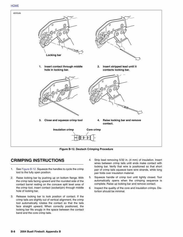
1. See Figure B-12. Squeeze the handles to cycle the crimptool to the fully open position.
2. Raise locking bar by pushing up on bottom flange. Withthe crimp tails facing upward and the rounded side of thecontact barrel resting on the concave split level area ofthe crimp tool, insert contact (socket/pin) through middlehole of locking bar.
3. Release locking bar to lock position of contact. If thecrimp tails are slightly out of vertical alignment, the crimptool automatically rotates the contact so that the tailsface straight upward. When correctly positioned, thelocking bar fits snugly in the space between the contactband and the core crimp tails.
4. Strip lead removing 5/32 in. (4 mm) of insulation. Insertwires between crimp tails until ends make contact withlocking bar. Verify that wire is positioned so that shortpair of crimp tails squeeze bare wire strands, while longpair folds over insulation material.
5. Squeeze handle of crimp tool until tightly closed. Toolautomatically opens when the crimping sequence iscomplete. Raise up locking bar and remove contact.
6. Inspect the quality of the core and insulation crimps. Dis-tortion should be minimal.
Figure B-12. Deutsch Crimping Procedure
d0250x8x
Locking bar
1. Insert contact through middle hole in locking bar.
2. Insert stripped lead until it contacts locking bar.
3. Close and squeeze crimp tool 4. Raise locking bar and remove contact.
Insulation crimp Core crimp
2004 Buell Firebolt: Appendix B B-9
HOME
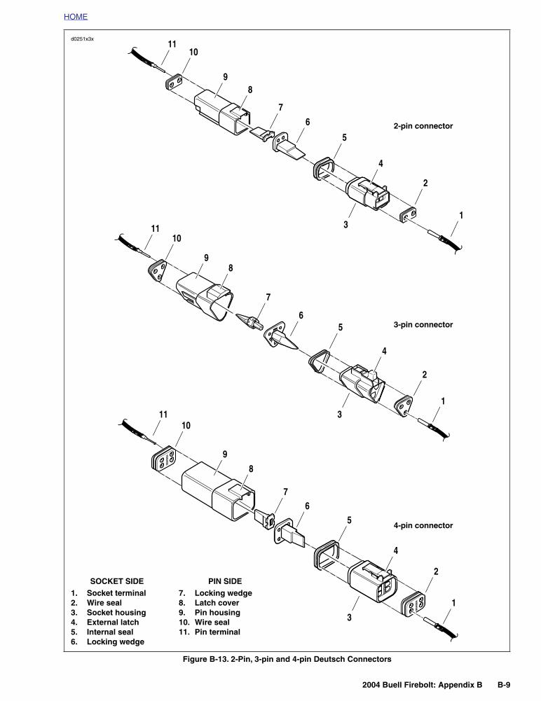
Figure B-13. 2-Pin, 3-pin and 4-pin Deutsch Connectors
1. Socket terminal2. Wire seal3. Socket housing4. External latch5. Internal seal6. Locking wedge
7. Locking wedge8. Latch cover9. Pin housing10. Wire seal11. Pin terminal
SOCKET SIDE PIN SIDE
1
2
4
5
6
7
89
1011
3
2-pin connector
1
2
4
3
56
7
8
1011
9
3-pin connector
1
2
4
56
7
8
9
1011
3
4-pin connector
d0251x3x
B-10 2004 Buell Firebolt: Appendix B
HOME
PACKARD ELECTRICAL CONNECTORS B.3
GENERAL
From a servicing standpoint, there are two basic types ofPackard electrical connectors, those with pull-to-seat termi-nals and those with push-to-seat terminals.
Look into the mating end of the connector. If it appears thatthe terminal can be extracted from this side, then it is proba-bly the pull-to-seat type.
At least one Packard pull-to-seat terminal can be easily rec-ognized by the presence of a locking ear. The ear engages aslot in the connector housing and prevents the terminal frombeing removed from the wire end side of the connector. Theear also acts as a strain relief in the event that the wires arepulled and further inhibits movement of the terminal insidethe chamber. For an example of this type of connector, notethe MAP sensor connector [80].
Unlike most connectors, where the terminals are pulled outthe wire end of the connector, to remove the terminals fromthe pull-to-seat connectors, the terminal is pushed out themating end of the connector. Once a
new
terminal is crimpedonto the end of the wire, the wire is pulled to draw the termi-nal back inside the chamber of the connector housing.
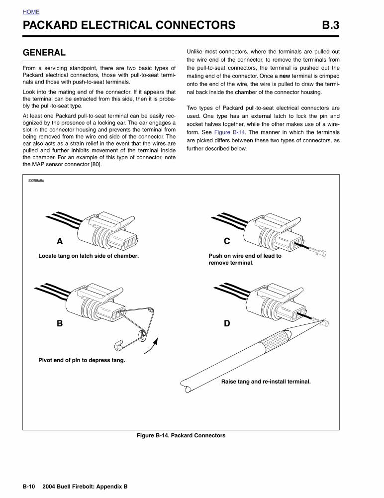
Two types of Packard pull-to-seat electrical connectors areused. One type has an external latch to lock the pin andsocket halves together, while the other makes use of a wire-form. See Figure B-14. The manner in which the terminalsare picked differs between these two types of connectors, asfurther described below.
Figure B-14. Packard Connectors
A
Locate tang on latch side of chamber.
C
Push on wire end of lead to remove terminal.
B
Pivot end of pin to depress tang.
D
Raise tang and re-install terminal.
d0258x8x
2004 Buell Firebolt: Appendix B B-11
HOME
PULL-TO-SEAT TERMINALS
Removing External Latch Type
To remove a pull-to-seat terminal from connectors with exter-nal latches, proceed as follows:
1. Remove the connector from the retaining device, ifpresent.
2. Bend back the external latch(es) slightly and separatethe pin and socket halves of the connector.
3. To free a pull-to-seat terminal from the connector hous-ing, first look into the mating end of the connector to findthe locking tang. See A in Figure B-14. The tangs arealways positioned in the middle of the chamber and areon the same side as the external latch. On those connec-tors with locking ears, the tang is on the side oppositethe ear.
4. At a slight angle, gently insert the point of a one inchsafety pin down the middle of the chamber (about 1/8inch) and pivot the end of the pin toward the terminalbody. When a click is heard, remove the pin and repeatthe procedure. See B in Figure B-14. The click is thesound of the tang returning to the locked position as itslips from the point of the pin. Pick at the tang in thismanner until the clicking stops and the pin seems to slidein at a slightly greater depth than it had previously. This isan indication that the tang has been depressed.
NOTES
●
On those terminals that have been extracted on a previ-ous occasion, no clicking sound may be heard when thepin is pivoted to depress the tang, but proceed as if theclicking is audible and then push on the wire end of thelead to check if the terminal is free.
●
When picking multiple terminals, the end of the pin maybecome malleable. For best results, continue the proce-dure with a new safety pin.
5. Remove the pin and push on the wire end of the lead toextract the terminal from the mating end of the connec-tor. See C in Figure B-14. If necessary, pull back the con-duit and remove the wire seal at the back of theconnector to introduce some slack in the wires.
NOTEA series of Packard Electrical Terminal Crimp Tools are avail-able to install Packard pin and socket terminals on wires. If
new
terminals must be installed, see Crimping Instructions.
Installing External Latch Type
NOTEFor wire location purposes, alpha characters are stampedinto the socket housings.
1. To install a terminal back into the chamber of the connec-tor housing, use a thin flat blade, like that on an X-Actoknife, and carefully bend the tang outward away from theterminal body. See D in Figure B-14.
2. Gently pull on the lead at the wire end of the connector todraw the terminal back into the chamber. A click is heardwhen the terminal is properly seated.
3. Push on the lead to verify that the terminal is locked inplace.
4. Push the pin and socket halves of the connector togetheruntil the latches “click.”
B-12 2004 Buell Firebolt: Appendix B
HOME
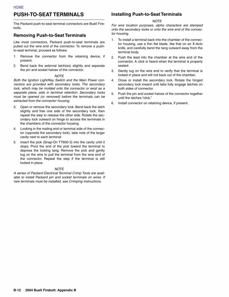
PUSH-TO-SEAT TERMINALS
The Packard push-to-seat terminal connectors are Buell Fire-bolts.
Removing Push-to-Seat Terminals
Like most connectors, Packard push-to-seat terminals arepulled out the wire end of the connector. To remove a push-to-seat terminal, proceed as follows:
1. Remove the connector from the retaining device, ifpresent.
2. Bend back the external latch(es) slightly and separatethe pin and socket halves of the connector.
NOTEBoth the Ignition Light/Key Switch and the Main Power con-nectors are provided with secondary locks. The secondarylock, which may be molded onto the connector or exist as aseparate piece, aids in terminal retention. Secondary locksmust be opened (or removed) before the terminals can beextracted from the connector housing.
3. Open or remove the secondary lock. Bend back the latchslightly and free one side of the secondary lock, thenrepeat the step to release the other side. Rotate the sec-ondary lock outward on hinge to access the terminals inthe chambers of the connector housing.
4. Looking in the mating end or terminal side of the connec-tor (opposite the secondary lock), take note of the largercavity next to each terminal.
5. Insert the pick (Snap-On TT600-3) into the cavity until itstops. Pivot the end of the pick toward the terminal todepress the locking tang. Remove the pick and gentlytug on the wire to pull the terminal from the wire end ofthe connector. Repeat the step if the terminal is stilllocked in place.
NOTEA series of Packard Electrical Terminal Crimp Tools are avail-able to install Packard pin and socket terminals on wires. Ifnew terminals must be installed, see Crimping Instructions.
Installing Push-to-Seat Terminals
NOTEFor wire location purposes, alpha characters are stampedonto the secondary locks or onto the wire end of the connec-tor housing.
1. To install a terminal back into the chamber of the connec-tor housing, use a thin flat blade, like that on an X-Actoknife, and carefully bend the tang outward away from theterminal body.
2. Push the lead into the chamber at the wire end of theconnector. A click is heard when the terminal is properlyseated.
3. Gently tug on the wire end to verify that the terminal islocked in place and will not back out of the chamber.
4. Close or install the secondary lock. Rotate the hingedsecondary lock inward until tabs fully engage latches onboth sides of connector.
5. Push the pin and socket halves of the connector togetheruntil the latches “click.”
6. Install connector on retaining device, if present.
2004 Buell Firebolt: Appendix B B-13
HOME
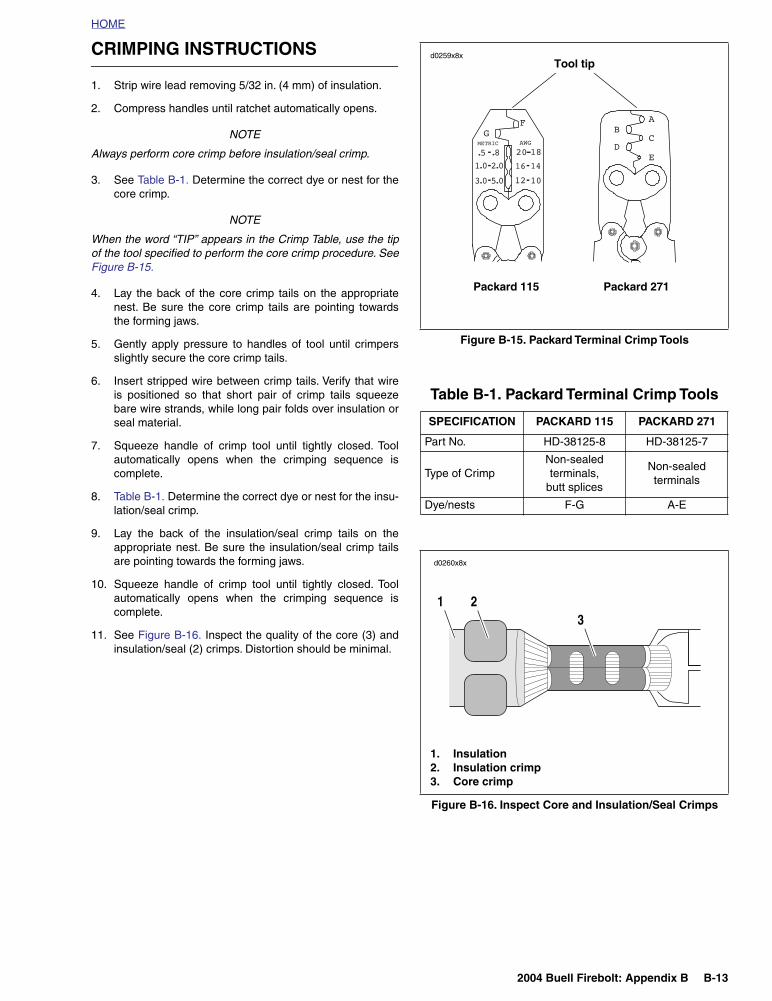
CRIMPING INSTRUCTIONS
1. Strip wire lead removing 5/32 in. (4 mm) of insulation.
2. Compress handles until ratchet automatically opens.
NOTE
Always perform core crimp before insulation/seal crimp.
3. See Table B-1. Determine the correct dye or nest for thecore crimp.
NOTE
When the word “TIP” appears in the Crimp Table, use the tipof the tool specified to perform the core crimp procedure. SeeFigure B-15.
4. Lay the back of the core crimp tails on the appropriatenest. Be sure the core crimp tails are pointing towardsthe forming jaws.
5. Gently apply pressure to handles of tool until crimpersslightly secure the core crimp tails.
6. Insert stripped wire between crimp tails. Verify that wireis positioned so that short pair of crimp tails squeezebare wire strands, while long pair folds over insulation orseal material.
7. Squeeze handle of crimp tool until tightly closed. Toolautomatically opens when the crimping sequence iscomplete.
8. Table B-1. Determine the correct dye or nest for the insu-lation/seal crimp.
9. Lay the back of the insulation/seal crimp tails on theappropriate nest. Be sure the insulation/seal crimp tailsare pointing towards the forming jaws.
10. Squeeze handle of crimp tool until tightly closed. Toolautomatically opens when the crimping sequence iscomplete.
11. See Figure B-16. Inspect the quality of the core (3) andinsulation/seal (2) crimps. Distortion should be minimal.
Figure B-15. Packard Terminal Crimp Tools
Table B-1. Packard Terminal Crimp Tools
SPECIFICATION PACKARD 115 PACKARD 271
Part No. HD-38125-8 HD-38125-7
Type of CrimpNon-sealed terminals,
butt splices
Non-sealed terminals
Dye/nests F-G A-E
Figure B-16. Inspect Core and Insulation/Seal Crimps
Tool tip
Packard 115 Packard 271
d0259x8x
d0260x8x
1. Insulation2. Insulation crimp3. Core crimp
1 23
B-14 2004 Buell Firebolt: Appendix B
HOME
ELECTRICAL CONNECTORS B.4
GENERAL
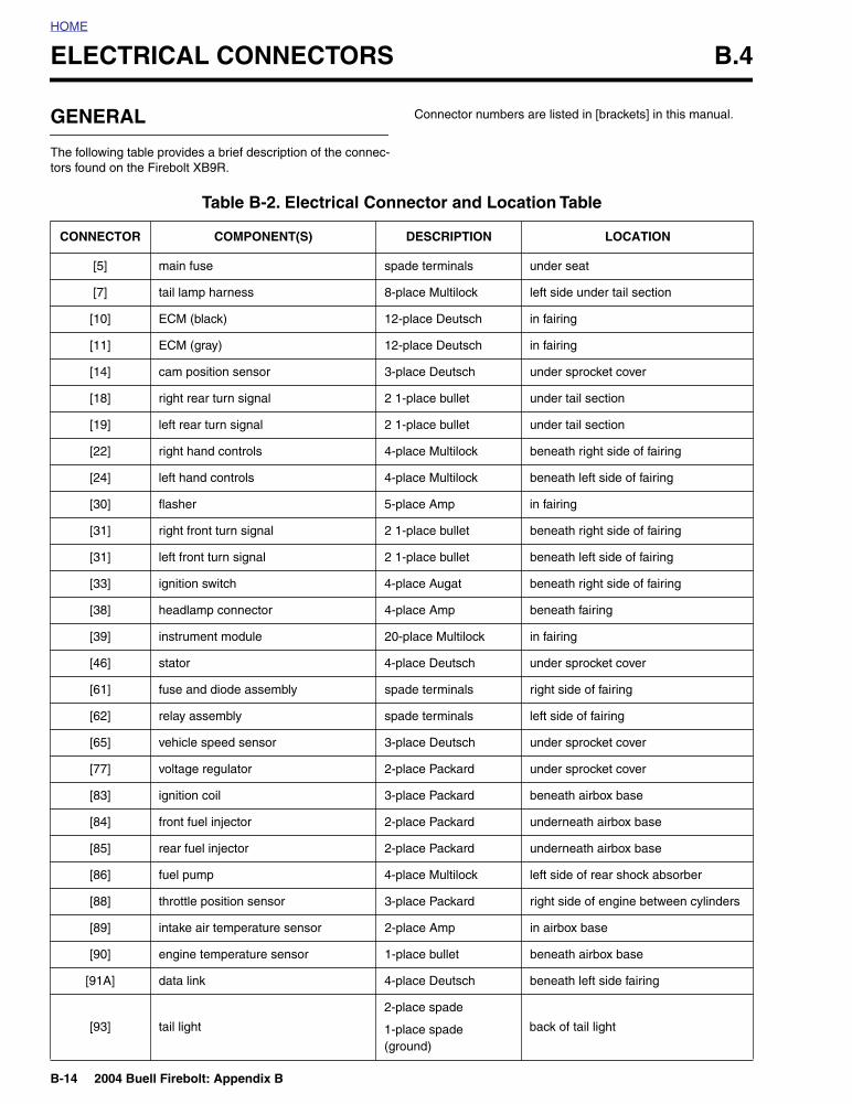
The following table provides a brief description of the connec-tors found on the Firebolt XB9R.
Connector numbers are listed in [brackets] in this manual.
Table B-2. Electrical Connector and Location Table
CONNECTOR COMPONENT(S) DESCRIPTION LOCATION
[5] main fuse spade terminals under seat
[7] tail lamp harness 8-place Multilock left side under tail section
[10] ECM (black) 12-place Deutsch in fairing
[11] ECM (gray) 12-place Deutsch in fairing
[14] cam position sensor 3-place Deutsch under sprocket cover
[18] right rear turn signal 2 1-place bullet under tail section
[19] left rear turn signal 2 1-place bullet under tail section
[22] right hand controls 4-place Multilock beneath right side of fairing
[24] left hand controls 4-place Multilock beneath left side of fairing
[30] flasher 5-place Amp in fairing
[31] right front turn signal 2 1-place bullet beneath right side of fairing
[31] left front turn signal 2 1-place bullet beneath left side of fairing
[33] ignition switch 4-place Augat beneath right side of fairing
[38] headlamp connector 4-place Amp beneath fairing
[39] instrument module 20-place Multilock in fairing
[46] stator 4-place Deutsch under sprocket cover
[61] fuse and diode assembly spade terminals right side of fairing
[62] relay assembly spade terminals left side of fairing
[65] vehicle speed sensor 3-place Deutsch under sprocket cover
[77] voltage regulator 2-place Packard under sprocket cover
[83] ignition coil 3-place Packard beneath airbox base
[84] front fuel injector 2-place Packard underneath airbox base
[85] rear fuel injector 2-place Packard underneath airbox base
[86] fuel pump 4-place Multilock left side of rear shock absorber
[88] throttle position sensor 3-place Packard right side of engine between cylinders
[89] intake air temperature sensor 2-place Amp in airbox base
[90] engine temperature sensor 1-place bullet beneath airbox base
[91A] data link 4-place Deutsch beneath left side fairing
[93] tail light
2-place spade
1-place spade (ground)
back of tail light
2004 Buell Firebolt: Appendix B B-15
HOME
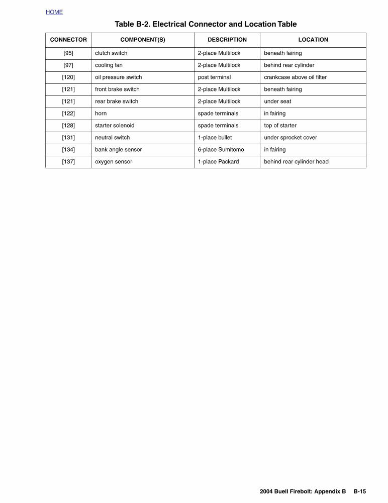
[95] clutch switch 2-place Multilock beneath fairing
[97] cooling fan 2-place Multilock behind rear cylinder
[120] oil pressure switch post terminal crankcase above oil filter
[121] front brake switch 2-place Multilock beneath fairing
[121] rear brake switch 2-place Multilock under seat
[122] horn spade terminals in fairing
[128] starter solenoid spade terminals top of starter
[131] neutral switch 1-place bullet under sprocket cover
[134] bank angle sensor 6-place Sumitomo in fairing
[137] oxygen sensor 1-place Packard behind rear cylinder head
Table B-2. Electrical Connector and Location Table
CONNECTOR COMPONENT(S) DESCRIPTION LOCATION
B-16 2004 Buell Firebolt: Appendix B
HOME
INDEX TO WIRING DIAGRAMS B.5
Table B-3. Wiring Diagrams
DIAGRAM PAGE
Main harness B-17
Engine management circuit B-18
Lighting circuit B-19
Horn and instruments circuit B-20
Starting circuit B-21
Starting and charging circuits B-22
Component circuits B-23
2004 Buell Firebolt: Electrical B-17
HOME
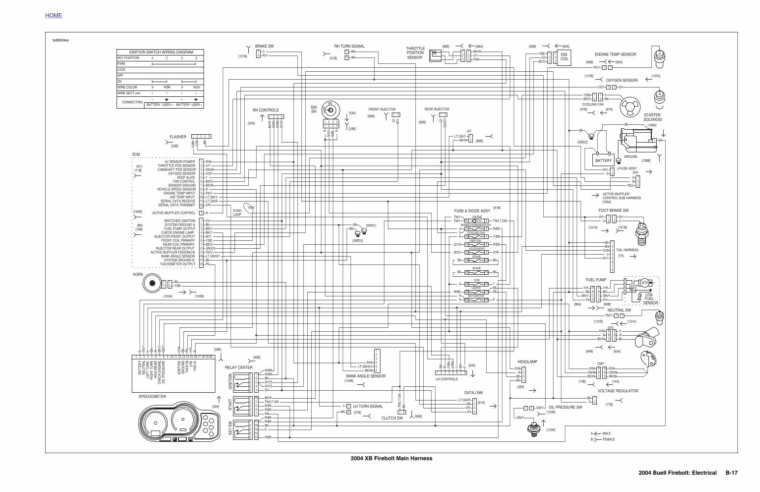
2004 XB Firebolt Main Harness
MTR
LOWFUEL
SENSOR
1 1
11
A=
B=
MALE
FEMALE
1 1
1 1
HORN
SPEEDOMETER
[39B]
[39A]
RELAY CENTER
[62B]
LH TURN SIGNAL[31B]
BANK ANGLE SENSOR
CLUTCH SW
[134B]
[95B]
LH CONTROLS
[120A]
[120B]
[38A]
[91A]
[24A]
DATA LINK
HEADLAMP
OIL PRESSURE SW
CMP
VOLTAGE REGULATOR
VSS
NEUTRAL SW
FUEL PUMP
[14B] [14A]
[77B]
[65B] [65A]
[86B][86A]
[131B] [131A]
[7A]
TAIL HARNESS
FOOT BRAKE SWFUSE & DIODE ASSY[61B]
[5A]
[165A]
GROUNDBATTERY
COOLING FAN
STARTERSOLENOID
[121A] [121B]
J-FUSE ASSY
CONTROL SUB HARNESSACTIVE MUFFLER
[GRD2]
[97B]
[128B]
[128A]
[97A]
ENGINE TEMP SENSOR
OXYGEN SENSOR[137B] [137A]
[90B] [90A]
[83B] [83A]
COILIGN.
THROTTLE
SENSORPOSITION
[88A][88B]
IAT
[89B]
[GRD1]
[GRD3]
REAR INJECTOR
[85B]
FRONT INJECTOR
[84B]
[33B]
IGNSWRH CONTROLS
[22A]
DYNOLOOP
[33A]
[31B]
RH TURN SIGNAL
[121B]
BRAKE SW
FLASHER
[30B]
ECM
(GY)
(BK)
[11B]
[164B]
[10B]
[122A] [122B]
2
9
23
24
22
20
19
12
11
10
8DIODE
KEY SWITCH
LIGHTS
ECM
SPARE
SPARE
ACCESSORY
IGNITION
COOLING FAN
BRAKE/HORN/MUFFLER3
17
18
16
14
13 BK
BK
BK
BK
6
5
4
1
1
1
1 R/W
PK
R
GY
V/BN O/W BK
BK/R
W/B
KW
/BK
GY/
O
RR
/GY
R/B
K R
LOC
K
W/YGY
GN
/GY
OBNVV/BN
Y/BK
WBE
BKTN/L
T.G
N
WY/R
PKBKO/W
GN
/YBK
/YWBNVTN
/Y
BKBK
BK/W
R/WV/Y
BN
BKR/YO
BK
BK
RR
R/BK
R
R/GY
GY/O
R
OO
TN/YTN/Y
BK/WLT.GN/Y
BE/OGY
Y/BE
PK/Y
V/GY GY
Y/BN YBK/O BK
BK
BK
GN
RR/Y
TN/V
OW
R/Y R/YO O
BNO/W
VR/Y
Y/R Y/RBK BK
BN/Y BN/YGY GY
TN/Y
R/W RW W
BK/W BK
R/W R/WGN/W GN/WBK/W BK/W
RBK
BKBE
WO/W
GYV/R
BKLT.GN/R
R/WLT.GN/GY
BK/W
V
R/BK
RBKR/BKR/BKGNR/BKR/BKTN/LT.GNBK/R
GYGY/OGY/OBKW/BK
R
BEBEY
O/W
R/BK
Y/BN
R/BK
TN/LT.GN
GN/Y
GN/Y
W/BK
Y/BKBK
BKLT.GN/GYTN/VGN/GYBE/OY/BE
Y/BE
W/YBK/YBN/YBKGY
W
V/RLT.GN/RLT.GN/YPK/YWBK/WBK/OYV/GYGN/WV/Y
VEHICLE SPEED SENSOR
INJECTOR REAR OUTPUT
5V SENSOR POWER
0
BDCA
0 0
+
1
R
1
+
USER + USER +
1
R/BK R/GY
BATTERY BATTERY
1
R
0 0
0PARK
KEY POSITION
IGNITION SWITCH WIRING DIAGRAM
CONNECTING
WIRE SECT mm
WIRE COLOR
ON
OFF
LOCK
SWITCHED IGNITION
THROTTLE POS SENSOR
SYSTEM GROUND A
CAMSHAFT POS SENSOR
FUEL PUMP OUTPUT
OXYGEN SENSOR
CHECK ENGINE LAMP
KEEP ALIVE
INJECTOR FRONT OUTPUT
FAN CONTROL
FRONT COIL PRIMARY
SENSOR GROUND
REAR COIL PRIMARY
SERIAL DATA TRANSMIT
ACTIVE MUFFLER CONTROL
TACHOMETER OUTPUT
SERIAL DATA RECEIVE
SYSTEM GROUND B
AIR TEMP INPUT
BANK ANGLE SENSOR
ENGINE TEMP INPUT
ACTIVE MUFFLER FEEDBACK
1
VSS
INLF
WTA
CH
ING
RO
UN
DIG
NIT
ION
OIL
PR
ES
SU
RE
CH
EC
K E
NG
INE
HIG
H B
EAM
RIG
HT
TUR
NLE
FT T
UR
NN
EUTR
ALBA
TTER
Y
10
2
2
2
5
3
3
3
5
5
5
4
4
4
2
2
2
1
1
1
3
3
3
3IGN
ITIO
NKE
Y SW
STAR
T4
4
4
4
5
5
5
7
6
6
6
8
15
7
7
7
6
13
8
8
8
9
14
9
9
9
2
10
10
10
19
12
12
12 2019181716151413
11
11
11
11
1
1
2
2
3
3
4
4
5
5
6
6
7
7
8
8
123456
1 2 3 4 5
1
1
A A
AA
1
11
2
2
B B
BB
2
22
IGN
3
3
C C
CC
3
33
4
4
D D
4
44
AA
1 122
BB
2 233
CC
3 3
11
1
1
1
1 1
1
1
2
1 1
1
1
1
1 1
11
2
22
2 2
21
3
2 2
2
2
2
2 2
22
bd0024xx
7
2004 Buell Firebolt: Electrical B-18
HOME
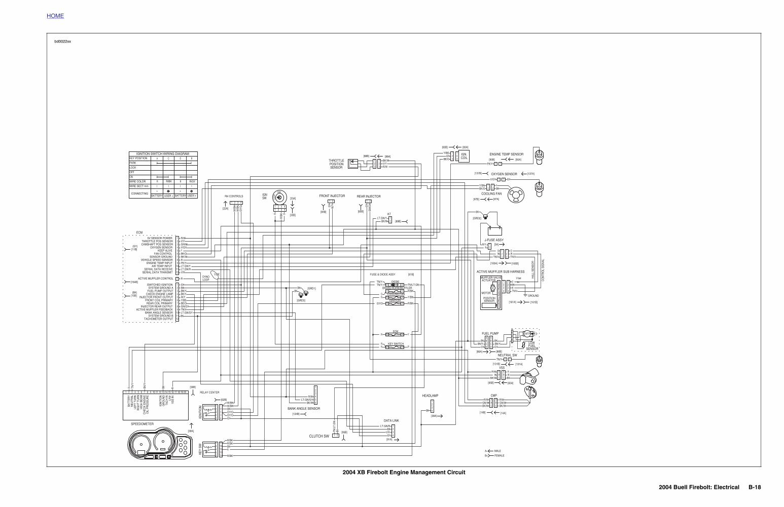
2004 XB Firebolt Engine Management Circuit
MTR
LOWFUEL
SENSOR
1
1
1 1
RELAY CENTER
[62B]
BANK ANGLE SENSOR
CLUTCH SW
[134B]
[95B]
[38A]
[91A]
DATA LINK
HEADLAMP CMP
VSS
NEUTRAL SW
FUEL PUMP
[14B] [14A]
[65B] [65A]
[86B][86A]
[131B]
FUSE & DIODE ASSY [61B]
[5A]
COOLING FAN
J-FUSE ASSY
[GRD2]
[97B] [97A]
OXYGEN SENSOR[137B] [137A]
[83B] [83A]
COILIGN.
IAT
[89B]
[GRD1]
[GRD3]
REAR INJECTOR
[85B]
FRONT INJECTOR
[84B][33B]
IGNSW
RH CONTROLS
[22A]
DYNOLOOP
[33A]
2
24
22
11
10
9
8
18
16
5
4
3
1
1
1 R/W
R
GY
W/B
KW
/BK
GY/
O
R
R/B
K R
LOC
K
W/YGY
GN
/GY
BKTN/L
T.G
N
WBKTN/Y
BK/Y
BKBK
RR
R
GY/O
R
TN/YTN/Y
BK/WLT.GN/Y
BE/OGY
Y/BE
PK/Y
V/GY GY
Y/BN YBK/O BK
BK
RR/Y
BK BKBN/Y BN/Y
GY GY
TN/Y
R/W RW W
BK/W BK
R/W R/WGN/W GN/WBK/W BK/W
BK
GYV/R
BKLT.GN/R
R/WLT.GN/GY
BK/W
R/BK
RBK
R/BK
GYGY/OGY/OBKW/BK
R
Y
R/BK
Y/BN
TN/LT.GN
W/BK
BKLT.GN/GY
GN/GYBE/OY/BE
Y/BE
W/YBK/YBN/YBKGY
V/RLT.GN/RLT.GN/YPK/YWBK/WBK/OYV/GYGN/WV/Y
2
2
5
3
3
5
5
4
4
2
2
1
1
3
3
3
IGN
ITIO
NKE
Y SW
4
4
4
5
5
6
6
15
7
7
13
8
8
9
14
9
9
10
10
19
12
12
11
11
11
123456 1
1
AA
1
11
2
2
BB
2
22
IGN
3
3
CC
3
33
4
4
DD
4
44
AA
AA
1 1
BB
BB
2 2
CC
CC
3 3
1
1
1 1
1
1
1
2
2
2 2
2
2
2
DIODE
COOLING FAN
BRAKE/HORN/MUFFLER
IGNITION
ECM
KEY SWITCH
1[90A]
ENGINE TEMP SENSOR
[90B]
[131A]
1
1 W
TN/V
O
[165A] [165B]
ACTIVE MUFFLER SUB HARNESS
TN/V
OW 2
1
3
ECM
SENSORPOSITION
THROTTLE[88B] [88A]
321 1
23 R/W
V/YBK/W
[161A]
GROUND
V batMUFFLER VALVEACTUATOR
MOTOR
SENSORPOSITION
DC
CO
NTR
OL
ELE
CTR
ON
ICS O
TN/VWBK
11
443322
[161B]
HA
LL S
EN
SO
R
CO
NTR
OL
SIG
NA
L
TN/VWO
3
12
R/BK
R/BK
0
BDCA
0 0
+
1
R
1
+
USER + USER +
1
R/BK R/GY
BATTERY BATTERY
1
R
0 0
0PARK
KEY POSITION
IGNITION SWITCH WIRING DIAGRAM
CONNECTING
WIRE SECT mm
WIRE COLOR
ON
OFF
LOCK
TACHOMETER OUTPUTSYSTEM GROUND B
BANK ANGLE SENSORACTIVE MUFFLER FEEDBACK
INJECTOR REAR OUTPUTREAR COIL PRIMARY
FRONT COIL PRIMARYINJECTOR FRONT OUTPUT
CHECK ENGINE LAMPFUEL PUMP OUTPUTSYSTEM GROUND A
SWITCHED IGNITION
ACTIVE MUFFLER CONTROL
SERIAL DATA TRANSMITSERIAL DATA RECEIVE
AIR TEMP INPUTENGINE TEMP INPUT
VEHICLE SPEED SENSORSENSOR GROUND
FAN CONTROLKEEP ALIVE
OXYGEN SENSORCAMSHAFT POS SENSORTHROTTLE POS SENSOR
5V SENSOR POWER
[11B](GY)
[164B]
(BK)[10B]
SPEEDOMETER
[39A]
1
VSS
INLF
WTA
CH
ING
RO
UN
DIG
NIT
ION
OIL
PR
ES
SU
RE
CH
EC
K E
NG
INE
HIG
H B
EAM
RIG
HT
TUR
NLE
FT T
UR
NN
EUTR
ALBA
TTER
Y
2 3 4 5 6 7 8 9 10 12 201918171615141311
[39B]
FEMALE
MALE
B=
A=
bd0022xx
2004 Buell Firebolt: Electrical B-19
HOME
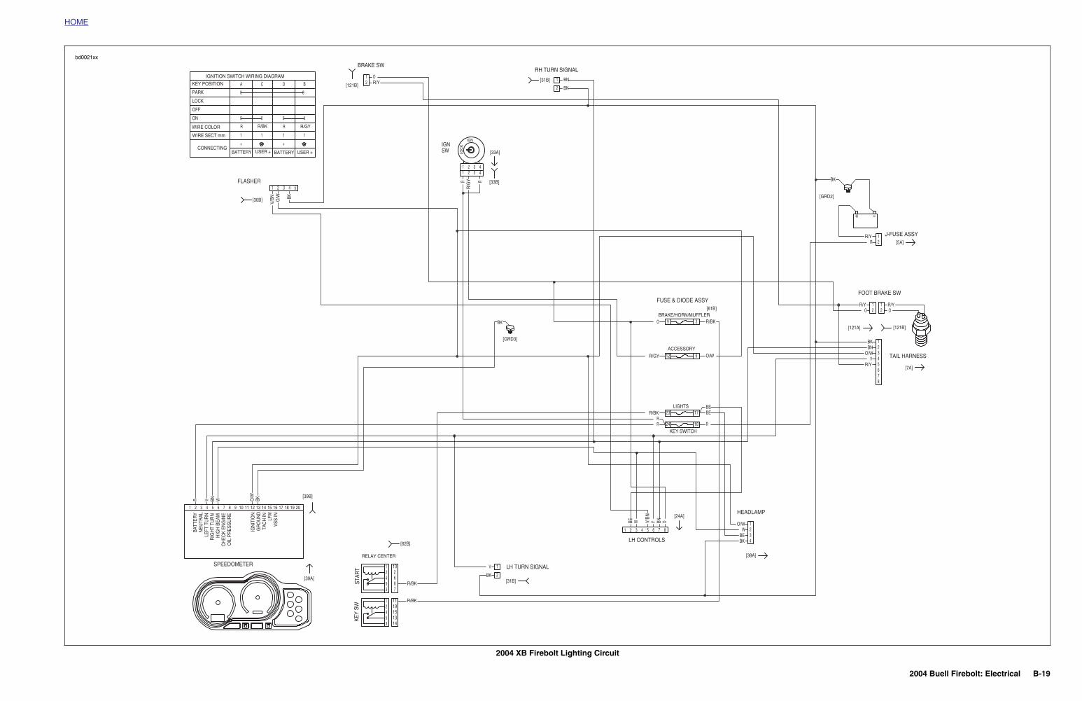
2004 XB Firebolt Lighting Circuit
RELAY CENTER
[62B]
LH TURN SIGNAL
[31B]
LH CONTROLS
[38A]
[24A]HEADLAMP
[7A]
TAIL HARNESS
FOOT BRAKE SWFUSE & DIODE ASSY
[61B]
[5A]
[121A] [121B]
J-FUSE ASSY
[GRD2]
[GRD3]
[33B]
IGNSW [33A]
[31B]
RH TURN SIGNAL
[121B]
BRAKE SW
FLASHER
[30B]
9
23
24
12
3
17
18
6
R
V/BN O/W BK
RR
/GY R
LOC
K
OBNVV/BN
WBE
BKO/W
WBNV
BK
BN
BKR/YO
BK
BK
RR
R/BK
R/GY
O
BK
RR/Y
R/Y R/YO O
BNO/W
VR/Y
BKBE
WO/W
V
R/BK
R/BK
R
BEBE
O/W
R/BK
10
3
3
5
5
4
4
2
2
1
1
KEY
SWST
ART
78
15
6
1314
2
1911
1
1
2
2
3
3
4
4
5
5
6
6
7
7
8
8
1 2 3 4 5
1
11
2
22
IGN
3
33
4
44
1
1 1
1
1 1
2
2 2
2
22
BRAKE/HORN/MUFFLER
ACCESSORY
LIGHTS
KEY SWITCH
0
BDCA
0 0
+
1
R
1
+
USER + USER +
1
R/BK R/GY
BATTERY BATTERY
1
R
0 0
0PARK
KEY POSITION
IGNITION SWITCH WIRING DIAGRAM
CONNECTING
WIRE SECT mm
WIRE COLOR
ON
OFF
LOCK
SPEEDOMETER
[39A]
1
VSS
INLF
WTA
CH
ING
RO
UN
DIG
NIT
ION
OIL
PR
ES
SU
RE
CH
EC
K E
NG
INE
HIG
H B
EAM
RIG
HT
TUR
NLE
FT T
UR
NN
EUTR
ALBA
TTER
Y
2 3 4 5 6 7 8 9 10 12 201918171615141311
[39B]
bd0021xx
2004 Buell Firebolt: Electrical B-20
HOME
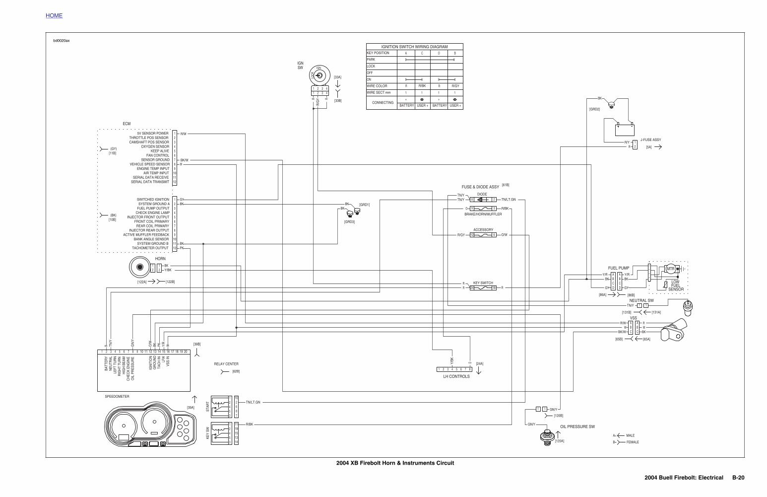
2004 XB Firebolt Horn & Instruments Circuit
MTR
LOWFUEL
SENSOR
1
11
HORN
LH CONTROLS
[120A]
[120B]
[24A]
OIL PRESSURE SW
VSS
NEUTRAL SW
FUEL PUMP
[65B] [65A]
[86B][86A]
[131B]
FUSE & DIODE ASSY [61B]
[5A]
J-FUSE ASSY
[GRD2]
[GRD1]
[GRD3]
[33B]
IGNSW
[33A]
ECM
[122A] [122B]
2
24
12
9
8
18
6
3
1
1
PK
R
RR
/GY R
LOC
K
OY/BK
WY/R
PKBKO/W
GN
/Y
TN/Y
BKBK
RR
R/GY
TN/Y
R/BKO
TN/Y
BK
RR/Y
Y/R Y/RBK BK
GY GY
TN/Y
R/W RW W
BK/W BK
R
O/W
TN/LT.GN
GN/Y
GN/Y
Y/BKBK
BK
BKGY
WBK/W
R/W
2
2
3
3
4
4
5
5
6
6
7
7
8
8
9
9
10
10
12
12
11
11
1 2 3 4 5 6 7 8
AA
11
BB
22
IGN
CC
33
DD
44
AABBCC
1
11
2
22
STAR
T
12453 7
862
10
KEY
SW
12453
15
1119
1314
TN/LT.GN
R/BK
[62B]
RELAY CENTER
DIODE
BRAKE/HORN/MUFFLER
ACCESSORY
KEY SWITCH
[131A]
1
0
BDCA
0 0
+
1
R
1
+
USER + USER +
1
R/BK R/GY
BATTERY BATTERY
1
R
0 0
0PARK
KEY POSITION
IGNITION SWITCH WIRING DIAGRAM
CONNECTING
WIRE SECT mm
WIRE COLOR
ON
OFF
LOCK
TACHOMETER OUTPUTSYSTEM GROUND B
BANK ANGLE SENSORACTIVE MUFFLER FEEDBACK
INJECTOR REAR OUTPUTREAR COIL PRIMARY
FRONT COIL PRIMARYINJECTOR FRONT OUTPUT
CHECK ENGINE LAMPFUEL PUMP OUTPUTSYSTEM GROUND A
SWITCHED IGNITION
SERIAL DATA TRANSMITSERIAL DATA RECEIVE
AIR TEMP INPUTENGINE TEMP INPUT
VEHICLE SPEED SENSORSENSOR GROUND
FAN CONTROLKEEP ALIVE
OXYGEN SENSORCAMSHAFT POS SENSORTHROTTLE POS SENSOR
5V SENSOR POWER
[11B](GY)
(BK)[10B]
SPEEDOMETER
[39A]
1
VSS
INLF
WTA
CH
ING
RO
UN
DIG
NIT
ION
OIL
PR
ES
SU
RE
CH
EC
K E
NG
INE
HIG
H B
EAM
RIG
HT
TUR
NLE
FT T
UR
NN
EUTR
ALBA
TTER
Y
2 3 4 5 6 7 8 9 10 12 201918171615141311
[39B]
FEMALE
MALE
B=
A=
bd0020ax
2004 Buell Firebolt: Electrical B-21
HOME
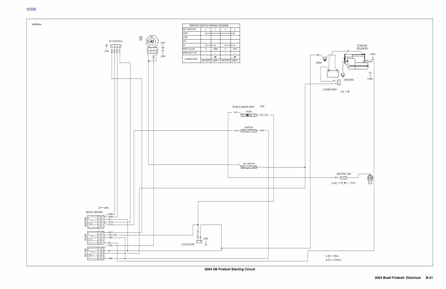
2004 XB Firebolt Starting Circuit
1
A=
B=
RELAY CENTER
[62B]
CLUTCH SW
[95B]
NEUTRAL SW
[131B]
FUSE & DIODE ASSY [61B]
[5A]
GROUND
STARTERSOLENOID
J-FUSE ASSY
[GRD2]
[128B]
[128A][33B]
IGNSW
RH CONTROLS
[22A]
[33A]
2
24
11
8
18
5
1
BK/R
W/B
KW
/BK
GY/
O
R
R/B
K R
LOC
K
BKTN/L
T.G
N
R
GY/O
TN/Y
BK
BK
GN
RR/Y
TN/Y
R/BK
RBK
R/BKGN
R/BKTN/LT.GNBK/R
GY/OGY/OBKW/BK
R
R/BK
TN/LT.GN
W/BK
10
5
3
3
3
5
5
5
4
4
4
2
2
2
1
1
1
3IGN
ITIO
NKE
Y SW
STAR
T
4
78
15
6
13
9
14
2
1911
1
11
2
22
IGN
3
33
4
44
1
1
1
2
2
DIODE
IGNITION
KEY SWITCH
[131A]
1
MALE
FEMALE
0
BDCA
0 0
+
1
R
1
+
USER + USER +
1
R/BK R/GY
BATTERY BATTERY
1
R
0 0
0PARK
KEY POSITION
IGNITION SWITCH WIRING DIAGRAM
CONNECTING
WIRE SECT mm
WIRE COLOR
ON
OFF
LOCK
bd0023xx
2004 Buell Firebolt: Electrical B-22
HOME
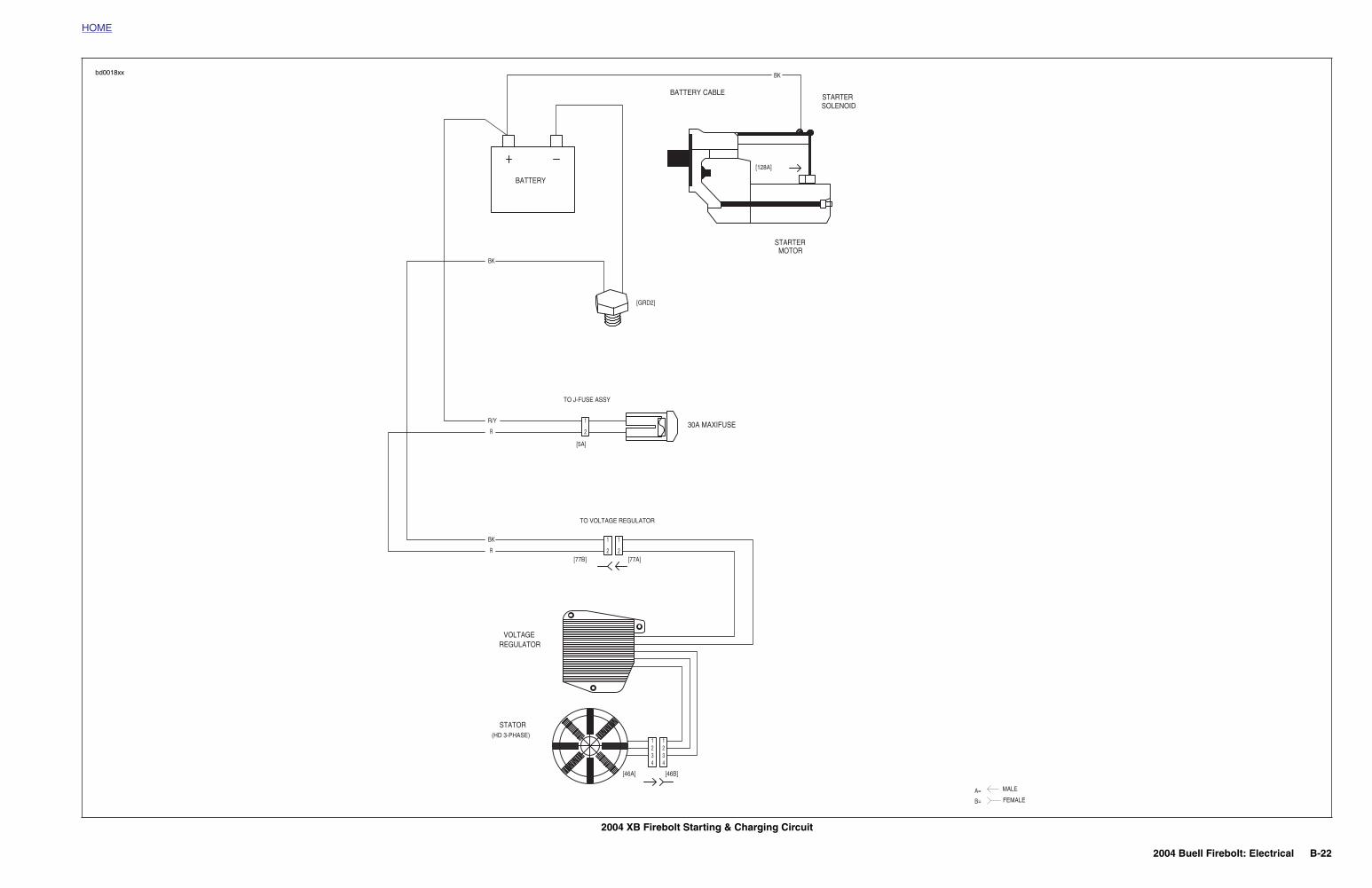
2004 XB Firebolt Starting & Charging Circuit
BATTERY CABLE
SOLENOIDSTARTER
MOTOR
[128A]
A=
B=
[46B][46A]
(HD 3-PHASE)
STATOR
REGULATORVOLTAGE
[77A][77B]
TO VOLTAGE REGULATOR
30A MAXIFUSE
TO J-FUSE ASSY
[5A]
[GRD2]
STARTER
BATTERY
BK
2
11
443322
2
11
R
BK
2
1
R
R/Y
BK
MALE
FEMALE
bd0018xx
2004 Buell Firebolt: Electrical B-23
HOME
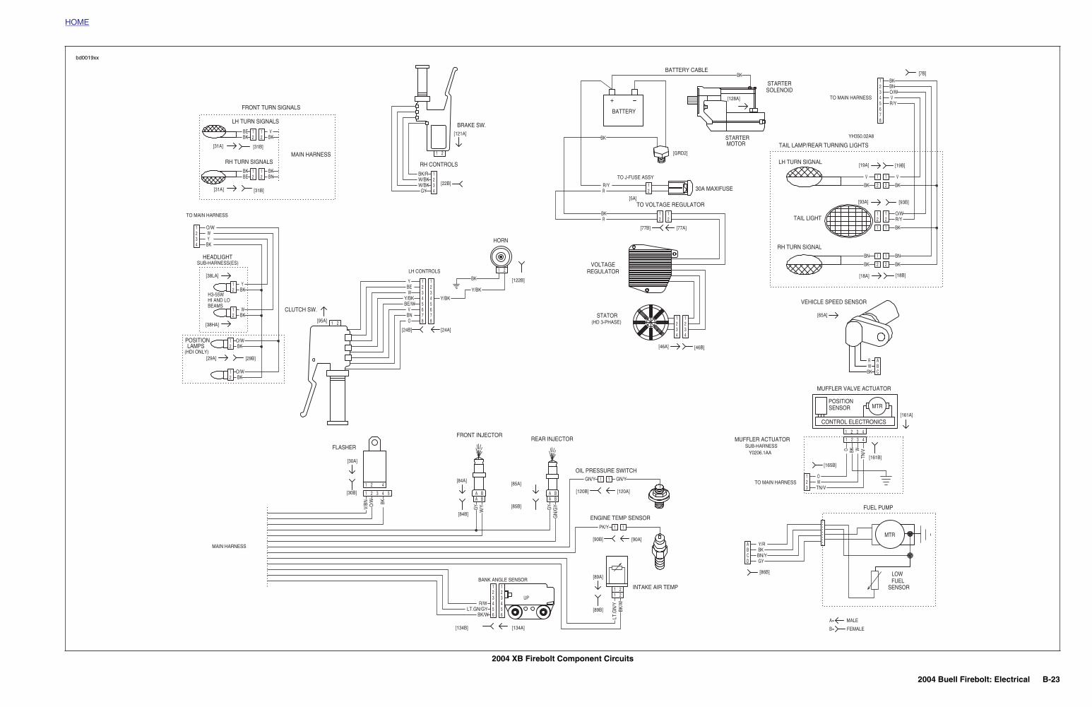
2004 XB Firebolt Component Circuits
MAIN HARNESS
MAIN HARNESS
TO MAIN HARNESS
SUB-HARNESS(ES)
[38LA]
[38HA]
[29B][29A]
HEADLIGHT
FRONT TURN SIGNALS
MTR
LOWFUEL
SENSOR
O BK
TN/VW
GYBKO
/WV/
BN
GN
/GYGY
W/Y
O
TN/VW
R/Y
R/Y
BK
BKBK
BK
BKBK
BN
BNBN
O/W
O/W
V
VV
BK
BK
21R/Y
R
RBK 1
2 21
1234 4
321
Y/R
GYBN/YBK
GN/Y
PK/Y
LT.G
N/Y
LT.GN/GYR/W
BK/W
BK/W
GN/Y
GY
Y/BK
OBNV
BE/W
BK
4
4 4
8 8
1
1
1
11
1
1
BEAMSHI AND LOH3-55W
1
1
A
1
1 432
321
22
11
11
2211
22
11
1
1 2
1
1 432
1
8765432
DCBA
1
111
1
54321
42
A
BKWR
222
66554433
BC
AA A
1
3
1
1
1
1
21
5 5
2
2
2
22
2
2
2
2
BBB B
2
4
2
2
2
2
6 6
3
3 3
7 7
W/BK
WY/BK
Y/BK
W/BK
BE
W
BK
BK
BK
O/W
(HDI ONLY)LAMPS
POSITION O/W
BKW
BKY
BN
BK
BE
BK
BK/R
Y
O/W
Y
BK
V
BK
BE
[86B]
REAR INJECTOR
OIL PRESSURE SWITCH
MUFFLER ACTUATORSUB-HARNESS
Y0206.1AA
TO MAIN HARNESS
POSITIONSENSOR MTR
CONTROL ELECTRONICS
MUFFLER VALVE ACTUATOR
TAIL LAMP/REAR TURNING LIGHTS
RH TURN SIGNAL
TAIL LIGHT
[93A] [93B]
[19A] [19B]
[7B]
[18A] [18B]
LH TURN SIGNAL
TO MAIN HARNESS
YH350.02A8
STATOR
REGULATORVOLTAGE
[128A]
BATTERY CABLE
SOLENOIDSTARTER
BATTERY
MOTORSTARTER
[GRD2]
[5A]
TO J-FUSE ASSY
30A MAXIFUSE
[77A]
[46A]
[165B]
[46B]
[161B]
[161A]
[77B]
TO VOLTAGE REGULATOR
(HD 3-PHASE)
FUEL PUMP
ENGINE TEMP SENSOR
VEHICLE SPEED SENSOR
INTAKE AIR TEMPBANK ANGLE SENSOR
UP
FRONT INJECTOR
FLASHER
[84A]
[30A]
[85A]
[120A]
[65A]
[90A]
[89A]
[134A]
[84B]
[30B]
[85B]
[120B]
[90B]
[89B]
[134B]
RH CONTROLS
BRAKE SW.
CLUTCH SW.
LH CONTROLS
HORN
[22B]
[24B]
[31B]
[31B]
RH TURN SIGNALS
LH TURN SIGNALS
[122B]
[24A]
[31A]
[31A]
[121A]
[95A]
FEMALE
MALE
B=
A=
bd0019xx