Remote Update Intel FPGA IP User Guide · 1. Remote Update Intel ® FPGA IP User Guide. The Remote...
41
Remote Update Intel FPGA IP User Guide Updated for Intel ® Quartus ® Prime Design Suite: 18.0 Subscribe Send Feedback UG-31005 | 2019.01.09 Latest document on the web: PDF | HTML
-
Upload
nguyenthuy -
Category
Documents
-
view
252 -
download
0
Transcript of Remote Update Intel FPGA IP User Guide · 1. Remote Update Intel ® FPGA IP User Guide. The Remote...

Remote Update Intel FPGA IP UserGuide
Updated for Intel® Quartus® Prime Design Suite: 18.0
SubscribeSend Feedback
UG-31005 | 2019.01.09Latest document on the web: PDF | HTML

Contents
1. Remote Update Intel® FPGA IP User Guide..................................................................... 31.1. Avalon®-MM in Remote Update Intel FPGA IP Core..................................................... 41.2. Intel Arria 10 Devices.............................................................................................5
1.2.1. Remote System Configuration Mode............................................................. 51.2.2. Remote System Configuration Components................................................... 71.2.3. Parameter Settings.................................................................................... 71.2.4. Ports........................................................................................................81.2.5. Parameters............................................................................................. 101.2.6. Avalon-MM Interface................................................................................ 101.2.7. Enabling Remote System Upgrade Circuitry................................................. 13
1.3. Arria II, Arria V, Cyclone V, Stratix IV, and Stratix V Devices...................................... 141.3.1. Remote System Configuration Mode........................................................... 141.3.2. Remote System Configuration Components................................................. 141.3.3. Parameter Settings.................................................................................. 151.3.4. Ports...................................................................................................... 161.3.5. Parameters............................................................................................. 191.3.6. Avalon-MM Interface ............................................................................... 201.3.7. Enabling Remote System Upgrade Circuitry................................................. 22
1.4. Cyclone IV Devices...............................................................................................231.4.1. Remote System Configuration Mode........................................................... 231.4.2. Remote System Configuration Components................................................. 231.4.3. Parameter Settings.................................................................................. 251.4.4. Ports...................................................................................................... 251.4.5. Parameters............................................................................................. 281.4.6. Remote Update Operation......................................................................... 291.4.7. Avalon-MM Interface ............................................................................... 311.4.8. Enabling Remote System Upgrade Circuitry................................................. 35
1.5. Flash Memory Programming Files........................................................................... 351.6. Design Examples................................................................................................. 36
1.6.1. Intel Arria 10 Remote Update Design Example............................................. 361.6.2. Cyclone V Remote Update Design Example.................................................. 37
1.7. Remote Update Intel FPGA IP User Guide Archives................................................... 381.8. Document Revision History for the Remote Update Intel FPGA IP User Guide................38
Contents
Remote Update Intel FPGA IP User Guide Send Feedback
2

1. Remote Update Intel® FPGA IP User GuideThe Remote Update Intel® FPGA IP core implements a device reconfiguration usingdedicated remote system upgrade circuitry available in supported devices. Remotesystem upgrade helps you deliver feature enhancements and bug fixes withoutrecalling your product, reduces time-to-market, and extends product life. The RemoteUpdate Intel FPGA IP core commands the configuration circuitry to start areconfiguration cycle.
The dedicated circuitry performs error detection during and after the configurationprocess. When the dedicated circuitry detects errors, the circuitry facilitates systemrecovery by reverting back to a safe, default factory configuration image and thenprovides error status information.
The following figures shows a functional diagram for a typical remote system upgradeprocess.
Figure 1. Typical Remote System Upgrade Process
New Application ImageDevelopment Location
Remote System Upgrade (RSU)
ControlModule
FlashController
RSUIP Core
Control Modulereceive data from network
and update the new image intothe flash
Control Moduletrigger reconfiguration
to new image using RSU IP core
Flash
Reconfiguration to new application image
Configuration Datasent through network
Note: Intel recommends that you use the following Remote Update Intel FPGA IP core inputclock (fMAX) values:
• 10 MHz— for Arria® II and Stratix® IV devices
• 20 MHz—for other supported devices
UG-31005 | 2019.01.09
Send Feedback
Intel Corporation. All rights reserved. Intel, the Intel logo, Altera, Arria, Cyclone, Enpirion, MAX, Nios, Quartusand Stratix words and logos are trademarks of Intel Corporation or its subsidiaries in the U.S. and/or othercountries. Intel warrants performance of its FPGA and semiconductor products to current specifications inaccordance with Intel's standard warranty, but reserves the right to make changes to any products and servicesat any time without notice. Intel assumes no responsibility or liability arising out of the application or use of anyinformation, product, or service described herein except as expressly agreed to in writing by Intel. Intelcustomers are advised to obtain the latest version of device specifications before relying on any publishedinformation and before placing orders for products or services.*Other names and brands may be claimed as the property of others.
ISO9001:2015Registered

Figure 2. High-Level Block Diagram of Remote System Upgrade
FPGA
Nios II Processoror User Logic
Passive Serial andFast Passive Parallel
Configuration Scheme
FlashMemory
MAX II,MAX V orMAX 10
FPGA
Nios II Processoror User Logic
EPCS,EPCQ orEPCQ-L
FPGA
Nios II Processoror User Logic
SupportedParallel
Flash
Active SerialConfiguration Scheme
Active ParallelConfiguration Scheme
(Cyclone IV devices only)
Note: The remote system upgrade feature support for each configuration scheme variesbetween device family. For more information about the configuration scheme and theremote system upgrade feature, please refer to the configuration chapter of therespective device family handbook.
Related Information
• Remote Update Intel FPGA IP Core Knowledge Base
• Configuration Support Center
• Introduction to Intel FPGA IP CoresProvides general information about all Intel FPGA IP cores, includingparameterizing, generating, upgrading, and simulating IP cores.
• Creating Version-Independent IP and Qsys Simulation ScriptsCreate simulation scripts that do not require manual updates for software or IPversion upgrades.
• Project Management Best PracticesGuidelines for efficient management and portability of your project and IP files.
• Remote Update Intel FPGA IP User Guide Archives on page 38Provides a list of user guides for previous versions of the Remote Update IntelFPGA IP core.
1.1. Avalon®-MM in Remote Update Intel FPGA IP Core
The Avalon®-MM interface is supported in the Remote Update Intel FPGA IP core. Youcan only use the IP core either with or without Avalon-MM interface. You caninstantiate the Avalon-MM Interface by turning on the Add support for AvalonInterface option in Remote Update Intel FPGA IP parameter editor.
Note: The Avalon-MM support for Remote Update Intel FPGA IP core is available in IntelQuartus® Prime software version 15.0 and onwards.
1. Remote Update Intel® FPGA IP User Guide
UG-31005 | 2019.01.09
Remote Update Intel FPGA IP User Guide Send Feedback
4

Figure 3. Remote Update Intel FPGA IP Core Implementation with and without Avalon-MM InterfaceFigure shows the Avalon Remote update support architecture which consists of 2 components; Remote IntelFPGA IP core and Avalon remote update controller. If Avalon interface is enabled, the conduit interfaces ofRemote Update Intel FPGA IP core will connect to conduit interface of the controller.
Avalon RemoteUpdate Controller
Avalon RemoteUpdate Controller
Remote UpdateIntel FPGA IP Core
Remote Update Intel FPGA IP core without Avalon-MM Interface
Remote Update Intel FPGA IP core with Avalon-MM Interface
Remote UpdateIntel FPGA IP Core
1.2. Intel Arria 10 Devices
1.2.1. Remote System Configuration Mode
Remote configuration supports “Direct to application” (DTA) and “Application toApplication” update. Remote configuration only supports a 4-byte address scheme sothere is no support for devices with densities smaller than 128 Mbit.
1. Remote Update Intel® FPGA IP User Guide
UG-31005 | 2019.01.09
Send Feedback Remote Update Intel FPGA IP User Guide
5

Figure 4. Transitions Between Factory and Application Configurations in RemoteUpdate Mode
After POR ornCONFIG Assertion
Read Start Addressfrom Flash
Load ApplicationNumber POF
After POR ornCONFIG Assertion
Load Factory POF
Enter FactoryUser Mode
Enter ApplicationUser Mode
Trigger reconfiguration & Start Address = 0or externaly pulse nCONFIG
Trigger reconfiguration & Start Address = 0or externaly pulse nCONFIG
Reconfiguration & Start Address > 0 and not 32
Error Count > 3
WatchdogTimeout
Error Count <= 3
No Error
Factory Configuration Application Configuration
Reconfiguration &Start Address = 32
Reconfiguration &Start Address = 32
Reconfiguration &Start Address > 0
and not 32
When you use low-voltage quad-serial configuration (EPCQ-L) devices, the remoteupdate mode allows a configuration space to start at any flash sector boundary. Thiscapability allows a maximum of 512 pages in the EPCQ-L256 device and 1024 pages inthe EPCQ-L512 device, in which the minimum size of each page is 512 Kbits.Additionally, the remote update mode features an optional user watchdog timer thatcan detect functional errors in an application configuration.
Note: When error occurs, the AS controller will load the same application configurationimage for three times before reverting to factory configuration image. By that time,the total time taken exceeds 100ms and violates the PCIe boot-up time when usingCvP configuration mode. If your design is sensitive to the PCIe boot-up requirement,Intel recommends that you do not use the direct-to-application feature.
Note: Intel recommends that you set a fixed start address and never update the startaddress during user mode. You should only overwrite an existing applicationconfiguration image when you have a new application image. This is to avoid thefactory configuration image to be erased unintentionally every time you update thestart address.
1. Remote Update Intel® FPGA IP User Guide
UG-31005 | 2019.01.09
Remote Update Intel FPGA IP User Guide Send Feedback
6

1.2.2. Remote System Configuration Components
Table 1. Remote System Configuration Components in Intel Arria 10 Devices
Components Details
Page mode feature The dedicated 32-bit start address register PGM[31..0] holds the start address.
Factory configuration Factory configuration can be set as the default configuration setup depending on the addresspointer set.The factory configuration loads into the device upon power-up.If a system encounters an error while loading application configuration data or if the devicereconfigures due to nCONFIG assertion, the device loads the factory configuration. The remotesystem configuration register determines the reason for factory configuration. Based on thisinformation, the factory configuration determines which application configuration to load.
Applicationconfiguration
Application configuration can be the default configuration setup depending on the address pointerset.The application configuration loads into the device upon power-up.The application configuration is the configuration data from a remote source and the data isstored in different locations or pages of the memory storage device, excluding the factory page.
Watchdog timer A watchdog timer is a circuit that determines the functionality of another mechanism. Thewatchdog timer functions like a time delay relay that remains in the reset state while anapplication runs properly.Intel Arria 10 devices are equipped with a built-in watchdog timer for remote systemconfiguration to prevent a faulty application configuration from indefinitely stalling the device.The timer is a 29-bit counter, but you use only the upper 12 bits to set the value for the watchdogtimer.The timer begins counting after the device goes into user mode. To ensure the applicationconfiguration is valid, you must continuously reset the watchdog reset_timer within a specificduration during user mode operation.If the application configuration does not reset the user watchdog timer before time expires, thededicated circuitry reconfigures the device with the factory configuration and resets the userwatchdog timer.
Remote update sub-block
The remote update sub-block manages the remote configuration feature. A remote configurationstate machine controls this sub-block. This sub-block generates the control signals required tocontrol the various configuration registers.
Remote configurationregisters
The remote configuration registers keep track of page addresses and the cause of configurationerrors. You can control both the update and shift registers. The status and control registers arecontrolled by internal logic, but are read via the shift register. The control register is 38-bits wide.For details about configuration registers, refer to the Configuration, Design Security, and RemoteSystem Upgrades chapter in the Intel Arria 10 Core Fabric and General Purpose I/Os Handbook.
Related Information
Intel Arria 10 Core Fabric and General Purpose I/Os HandbookProvides more information about configuration registers of the Intel Arria 10devices.
1.2.3. Parameter Settings
Table 2. Remote Update Intel FPGA IP Core Parameters for Intel Arria 10 Devices
GUI Name Values Description
Which operation modewill you be using?
REMOTE Specifies the configuration mode of the Remote UpdateIntel FPGA IP core.
Which configurationdevice will you beusing?
EPCQ-L device Choose the configuration device you are using.
continued...
1. Remote Update Intel® FPGA IP User Guide
UG-31005 | 2019.01.09
Send Feedback Remote Update Intel FPGA IP User Guide
7

GUI Name Values Description
Add support forwriting configurationparameters
— Enable this if you need to write configurationparameters.
Add support forAvalon Interface
— Enable this if you are using Avalon interface.
Enable reconfig POFchecking
— Not available as this option is handled by the FPGA AScontroller instead of the Remote Update Intel FPGA IPcore. The same application image is loaded for threetimes before reverting to factory application image, toensure no unexpected system failure occurred.
1.2.4. Ports
Table 3. Remote Update Intel FPGA IP Core Ports for Intel Arria 10 Devices
Name Port Required? Description
read_param Input No Read signal for the parameter specified in param[] input port andfed to data_out[] output port.Signal indicating the parameter specified on the param[] portshould be read. The number of bits set on data_out[] depends onthe parameter type. The signal is sampled at the rising clock edge.Assert the signal for only one clock cycle to prevent the parameterfrom being read again in a subsequent clock cycle.The busy signal is activated as soon as read_param is read asactive. While the parameter is being read, the busy signal remainsasserted, and data_out[] has invalid data. When the busy signal isdeactivated and data_out[] has a valid data, another parametercan be read.
write_param Input No Write signal for parameter specified in param[] and with valuespecified in data_in[].Signal indicating parameter specified with param[] should bewritten into remote update block with the value specified indata_in[]. The number of bits read from data_in[] depends onthe parameter type.The signal is sampled at the rising clock edge. The signal should beasserted for only one clock cycle to prevent the parameter frombeing rewritten on a subsequent clock cycle. The busy signal isactivated as soon as write_param is read as being active. Whilethe parameter is being written, the busy signal remains asserted,and input to data_ in[] is ignored. When the busy signal isdeactivated, another parameter can be written. This signal is onlyvalid in factory configuration mode because parameters cannot bewritten in Application configuration mode.
param[] Input No Bus that specifies which parameter need to be read or updated.A 3-bit bus that selects the parameter to be read or updated. If leftunconnected, the default value for this port is 000.
data_in[] Input No Data input for writing parameter data into the remote update block.Input bus for parameter data.For some parameters, not all bits are used. In this case, the lower-order bits are used (for example, status values use bits [4:0]).If left unconnected, this bus defaults to 0. The port is ignored if thecurrent configuration is the Application configuration.A 32-bit bus width (4-bytes addressing configuration device, forexample EPCQ-L256) in the Intel Quartus Prime software version14.0 or later.
continued...
1. Remote Update Intel® FPGA IP User Guide
UG-31005 | 2019.01.09
Remote Update Intel FPGA IP User Guide Send Feedback
8

Name Port Required? Description
reconfig Input Yes Signal indicating that reconfiguration of the part should begin usingthe current parameter settings. A value of 1 indicatesreconfiguration should begin. This signal is ignored if the busy signalis asserted to ensure all parameters are completely written beforereconfiguration begins.
reset_timer Input No Reset signal for watchdog timer.Signal indicating the internal watchdog timer should be reset. Unlikeother inputs, this signal is not affected by the busy signal and canreset the timer even when the busy signal is asserted.A falling edge of this signal triggers a reset of the user watchdogtimer.For the timing specification of this parameter, refer to the specificdevice handbook.
clock Input Yes Clock input to the remote update block.Clock input to control the machine and to drive the remote updateblock during the update of parameters.This port must be connected to a valid clock.
reset Input Yes This is an active high signal. Asserting this signal high will reset theIP core.Asynchronous reset input to the IP core to initialize the machine to avalid state. The machine must be reset before first use, otherwisethe state is not guaranteed to be valid.
busy Output No Busy signal that indicates when remote update block is reading orwriting data.While this signal is asserted, the machine ignores most of its inputsand cannot be altered until the machine deasserts this signal.Therefore, changes are made only when the machine is not busy.This signal goes high when read_param or write_ param isasserted, and remains high until the read or write operationcompletes.
data_out[] Output No Data output when reading parameters.This bus holds read parameter data from the remote update block.The param[] value specifies the parameter to read. When theread_param signal is asserted, the parameter value is loaded anddriven on this bus. Data is valid when the busy signal is deasserted.If left unconnected, the default value for the port is 0.The width of this bus is device-dependent. For the Intel QuartusPrime software version 14.0 and later, the bus width is 32-bit—using4-byte addressing configuration device, for example EPCQL-256.
ctl_nupdt Input Yes This port allows you to select which register to be read wheneverread_param operation is running.• A logic high selects the Control Register—register containing the
current remote update settings such as watchdog timer settings,configuration mode (AnF), and page address.
• A logic low selects the Update Register—register containingsimilar data as held in the Control Register, but the values areupdated via write_param operation for use in nextreconfiguration.
1. Remote Update Intel® FPGA IP User Guide
UG-31005 | 2019.01.09
Send Feedback Remote Update Intel FPGA IP User Guide
9

1.2.5. Parameters
Table 4. Parameter Type and Corresponding Parameter Bit Width Mapping for IntelArria 10 Devices
Bit Parameter Width Comments
000 Reconfiguration triggerconditions (Read Only) 5
• Bit 4—wdtimer_source: User watchdog timer timeout.• Bit 3—nconfig_source: External configuration reset
(nCONFIG) assertion.• Bit 2—runconfig_source: Configuration reset triggered
from logic array.• Bit 1—nstatus_source: nSTATUS asserted by an external
device as the result of an error.• Bit 0—crcerror_source: CRC error during application
configuration.The POR value for all bits are 0.
001 Illegal Value
010 Watchdog Timeout Value 12 —
011 Watchdog Enable 1 —
100 Page Select 32 For the Intel Quartus Prime software version 14.0 and later:• Width of 32 when reading and writing the start address.• For active serial devices using 32-bit addressing, such as
EPCQL-256, PGM[31..2] corresponds to the upper 30 bits ofthe 32-bits start address. PGM[1..0] is read as 2'b0.
101 Configuration Mode (AnF) 1 This parameter is set to 1 in application page and is set to 0 infactory page. In remote update mode, this parameter can beread and written.Before loading the application page in remote update mode, Intelrecommends that you set this parameter to 1. The content of thecontrol register cannot be read properly if you fail to do so.
110 Illegal Value
111 Illegal Value
1.2.6. Avalon-MM Interface
1.2.6.1. Control Status Register Signals
Table 5. Remote Update Intel FPGA IP Core Avalon-MM Control Status RegisterSignals for Intel Arria 10 Devices
Name Width Direction Description
clk 1 Input Clock input.
reset 1 Input Reset input.
avl_csr_address 3 Input Address bus.
avl_csr_read 1 Input Perform a read transaction.
avl_csr_write 1 Input Perform a write transaction.
avl_csr_readdata 32 Output Read data from IP.
continued...
1. Remote Update Intel® FPGA IP User Guide
UG-31005 | 2019.01.09
Remote Update Intel FPGA IP User Guide Send Feedback
10

Name Width Direction Description
avl_csr_readdata_valid 1 Output Indicate when read data is valid.
avl_csr_writedata 32 Input Write data to IP.
avl_csr_waitrequest 1 Output Waitrequest signal high indicates the core is busy.
1.2.6.1.1. Control Status Register Write Operation
To execute the write operation for the control status register, perform the followingsteps:
1. Asserts the avl_csr_write high.
2. Write a correct address of the register in the avl_csr_address bus. Refer to theRegister Map for register information.
3. Write data into the avl_csr_writedata bus.
Related Information
Register Map on page 12
1.2.6.1.2. Control Status Register Read Operation
To execute the read operation for the control status register, perform the followingsteps:
1. Asserts avl_csr_read high.
2. Write a correct address of the register in the avl_csr_address bus. Refer to theRegister Map for register information.
3. Wait for the avl_csr_readdata_valid signal to go high.
4. Retrieve read data from avl_csr_readdata.
1.2.6.1.3. Operations Example Waveforms
Note: Intel recommends that you verify the Remote Update Intel FPGA IP core for Intel Arria10 devices in hardware because the simulation model is not supported for RemoteUpdate Intel FPGA IP core for Intel Arria 10 devices.
Figure 5. Waveform for Write Operation
1. Remote Update Intel® FPGA IP User Guide
UG-31005 | 2019.01.09
Send Feedback Remote Update Intel FPGA IP User Guide
11

Figure 6. Waveform for Read Operation
Figure 7. Waveform for RU_CTL_NUPDT OperationThe RU_CTL_NUPDT will hold the value until a new value is inserted.
Figure 8. Waveform for Reset Timer and Reconfiguration OperationThe RU_RECONFIG will hold the value until the reconfiguration process is done.
1.2.6.2. Register Map
Table 6. Remote Update Intel FPGA IP Core Avalon-MM Register Map for Intel Arria 10Devices• The IP core can read or write each field separately as each command has different parameter value.
• The default value for the registers is 0.
Register Name AddressOffset
Width R/W Description
RU_RECONFIG_TRIGGER_CONDITIONS
0x0 5 Read Read configuration trigger conditions.
continued...
1. Remote Update Intel® FPGA IP User Guide
UG-31005 | 2019.01.09
Remote Update Intel FPGA IP User Guide Send Feedback
12

Register Name AddressOffset
Width R/W Description
• Bit 4—wdtimer_source: Userwatchdog timer timeout
• Bit 3—nconfig_source: Externalconfiguration reset (nCONFIG) assertion.
• Bit 2—runconfig_source:Configuration reset triggered from logicarray
• Bit 1—nstatus_source: nSTATUSasserted by an external device as theresult of an error
• Bit 0—crcerror_source: CRC errorduring application configuration.
RU_WATCHDOG_TIMEOUT 0x1 12 Read/Write Read or write watchdog timeout value.
RU_WATCHDOG_ENABLE 0x2 1 Read/Write Enable or disable watchdog timeout.• 0: Disable• 1: Enable
RU_PAGE_SELECT 0x3 24 or 32 Read/Write Read or write start address of theconfiguration image.
RU_CONFIGURATION_MODE 0x4 1 Read/Write Write configuration mode set to 1 inapplication page and 0 in factory page.
RU_RESET_TIMER 0x5 1 Write Write a value of 1 to this register to triggerreset timer of the remote update. The IP willautomatically trigger a reset pulse to thereset timer pin of the remote update.
RU_RECONFIG 0x6 1 Write Write a value of 1 to this register to triggerreconfiguration from a new image. The IPwill set 1 to the reconfig pin of the remoteupdate and hold this value until the processdone.
RU_CTL_NUPDT 0x7 1 Write Allow capturing of data from either Control/Update register by controlling ctl_nupdt.• 0: Capture value from Update Register• 1: Capture data from Control Register
1.2.7. Enabling Remote System Upgrade Circuitry
To enable the remote system upgrade feature, select Active Serial or ConfigurationDevice from the Configuration scheme list in the Configuration page of the Deviceand Pin Options dialog box in the Intel Quartus Prime software.
Intel-provided Remote Update Intel FPGA IP core provides a memory-like interface tothe remote system upgrade circuitry and handles the shift register read and writeprotocol in the device logic.
1. Remote Update Intel® FPGA IP User Guide
UG-31005 | 2019.01.09
Send Feedback Remote Update Intel FPGA IP User Guide
13

1.3. Arria II, Arria V, Cyclone V, Stratix IV, and Stratix V Devices
1.3.1. Remote System Configuration Mode
Remote Configuration Mode
Figure 9. Remote Configuration Mode
Power Up Set Control Registerand Reconfigure
Reload a Different Application
Reload a Different Application
Set Control Registerand Reconfigure
Configuration Error
Configuration Error
Configuration Error
Application 1Configuration
Application nConfiguration
FactoryConfiguration
(page 0)
When using with serial configuration (EPCS) or quad-serial configuration (EPCQ)devices, the remote update mode allows a configuration space to start at any flashsector boundary, allowing a maximum of 128 pages in the EPCS64 device and 32pages in the EPCS16 device, in which the minimum size of each page is 512 Kbits.Additionally, the remote update mode features a user watchdog timer that can detectfunctional errors in an application configuration.
1.3.2. Remote System Configuration Components
Table 7. Remote System Configuration Components in Arria II, Arria V, Cyclone® V,Stratix IV, and Stratix V Devices
Components Details
Page mode feature The dedicated 24-bit start address register PGM[23..0] holds the start address.
Factory configuration Factory configuration is the default configuration setup.In remote configuration mode, the factory configuration loads into the device upon power-up.If a system encounters an error while loading application configuration data or if the devicereconfigures due to nCONFIG assertion, the device loads the factory configuration. Theremote system configuration register determines the reason for factory configuration.Based on this information, the factory configuration determines which applicationconfiguration to load.
Application configuration The application configuration is the configuration data from a remote source and the data isstored in different locations or pages of the memory storage device, excluding the factorydefault page.
Watchdog timer A watchdog timer is a circuit that determines the functionality of another mechanism. Thewatchdog timer functions like a time delay relay that remains in the reset state while anapplication runs properly.
continued...
1. Remote Update Intel® FPGA IP User Guide
UG-31005 | 2019.01.09
Remote Update Intel FPGA IP User Guide Send Feedback
14

Components Details
Arria II, Arria V, Cyclone® V, Stratix IV, and Stratix V devices are equipped with a built-inwatchdog timer for remote system configuration to prevent a faulty applicationconfiguration from indefinitely stalling the device.The timer is a 29-bit counter, but you use only the upper 12 bits to set the value for thewatchdog timer.The timer begins counting after the device goes into user mode. If the applicationconfiguration does not reset the user watchdog timer before time expires, the dedicatedcircuitry reconfigures the device with the factory configuration and resets the userwatchdog timer.To ensure the application configuration is valid, you must continuously reset the watchdogreset_timer within a specific duration during user mode operation.
Remote update sub-block The remote update sub-block manages the remote configuration feature. A remoteconfiguration state machine controls this sub-block. This sub-block generates the controlsignals required to control the various configuration registers.
Remote configurationregisters
The remote configuration registers keep track of page addresses and the cause ofconfiguration errors. You can control both the update and shift registers. The status andcontrol registers are controlled by internal logic, but are read via the shift register. Thecontrol register is 38-bit wide.For details about configuration registers, refer to the Configuration, Design Security, andRemote System Upgrades chapter in the respective device handbook.
Related Information
• Arria V Device Handbook Volume 1: Device Interfaces and IntegrationProvides more information about configuration registers of the Arria V devices.
• Cyclone V Device Handbook Volume 1: Device Interfaces and IntegrationProvides more information about configuration registers of the Cyclone Vdevices.
• Stratix V Device Handbook Volume 1: Device Interfaces and IntegrationProvides more information about configuration registers of the Stratix Vdevices.
1.3.3. Parameter Settings
Table 8. Remote Update Intel FPGA IP Core Parameters for Arria II, Arria V, CycloneV, Stratix IV, and Stratix V Devices
GUI Name Values Description
Which operation modewill you be using?
REMOTE Specifies the configuration mode.
Which configurationdevice will you beusing?
• EPCS device• EPCQ device
Choose the configuration device you are using.
continued...
1. Remote Update Intel® FPGA IP User Guide
UG-31005 | 2019.01.09
Send Feedback Remote Update Intel FPGA IP User Guide
15

GUI Name Values Description
Add support forwriting configurationparameters
— Enable this if you need to write configurationparameters.
Add support forAvalon Interface(1)
— Enable this if you are using Avalon interface.
Enable reconfig POFchecking
— Allows you to enable .pof checking, which allows theremote update block to verify the existence of anapplication configuration image before the image isloaded. When you turn on this parameter, the RemoteUpdate Intel FPGA IP core checks the .pof and sends thereconfig signal. This option is disabled by default.
The POF checking feature detects and verifies the existence of an applicationconfiguration image before the image is loaded. Loading an invalid applicationconfiguration image may lead to unexpected behaviour of the FPGA including systemfailure. Examples of invalid application configuration images are:
• A partially programmed application image
• A blank application image
• An application image assigned with a wrong start address
1.3.4. Ports
Table 9. Remote Update Intel FPGA IP Core Ports for Arria II, Arria V, Cyclone V,Stratix IV, and Stratix V Devices
Name Port Required? Description
read_param Input No Read signal for the parameter specified in param[] inputport and fed to data_out[] output port.Signal indicating the parameter specified on the param[]port should be read. The number of bits set ondata_out[] depends on the parameter type. The signalis sampled at the rising clock edge. Assert the signal foronly one clock cycle to prevent the parameter from beingread again in a subsequent clock cycle.The busy signal is activated as soon as read_param isread as active. While the parameter is being read, thebusy signal remains asserted, and data_out[] hasinvalid data. When the busy signal is deactivated,data_out[] is valid, another parameter can be read.
write_param Input No Write signal for parameter specified in param[] and withvalue specified in data_in[].Signal indicating parameter specified with param[]should be written into remote update block with the valuespecified in data_in[]. The number of bits read fromdata_in[] depends on the parameter type.The signal is sampled at the rising clock edge. The signalshould be asserted for only one clock cycle to prevent theparameter from being rewritten on a subsequent clockcycle. The busy signal is activated as soon aswrite_param is read as being active. While theparameter is being written, the busy signal remains
continued...
(1) Parameter not available in Stratix II devices.
1. Remote Update Intel® FPGA IP User Guide
UG-31005 | 2019.01.09
Remote Update Intel FPGA IP User Guide Send Feedback
16

Name Port Required? Description
asserted, and input to data_in[] is ignored. When thebusy signal is deactivated, another parameter can bewritten. This signal is only valid in factory configurationmode because parameters cannot be written inapplication configuration mode.
param[] Input No Bus that specifies which parameter need to be read orupdated.A 3-bit bus that selects the parameter to be read orupdated. If left unconnected, the default value for thisport is 000.For more information, refer to Parameters on page 19.
data_in[] Input No Data input for writing parameter data into the remoteupdate block. Input bus for parameter data.For some parameters, not all bits are used. In this case,the lower-order bits are used (for example, status valuesuse bits [4:0]).If left unconnected, this bus defaults to 0. The port isignored if the current configuration is the Applicationconfiguration.A 24-bit bus width in the Intel Quartus Prime softwareversion 13.0 or earlier. For the Intel Quartus Primesoftware version 13.1 and later, the bus widths are asfollow:• 24-bit bus width—using 3-byte addressing
configuration device, for example EPCS128.• 32-bit bus width—using 4-byte addressing
configuration device, for example EPCQ256.
reconfig Input Yes Signal indicating that reconfiguration of the part shouldbegin using the current parameter settings. A value of 1indicates reconfiguration should begin. This signal isignored while the busy signal is asserted to ensure allparameters are completely written before reconfigurationbegins.
reset_timer Input No Reset signal for watchdog timer.Signal indicating the internal watchdog timer should bereset. Unlike other inputs, this signal is not affected bythe busy signal and can reset the timer even when thebusy signal is asserted.A falling edge of this signal triggers a reset of the userwatchdog timer.For the timing specification of this parameter, refer to thespecific device handbook.
clock Input Yes Clock input to the remote update block.Clock input to control the machine and to drive theremote update block during the update of parameters.This port must be connected to a valid clock.
reset Input Yes This is an active high signal. Asserting this signal high willreset the IP core.Asynchronous reset input to the IP core to initialize themachine to a valid state. The machine must be resetbefore first use, otherwise the state is not guaranteed tobe valid.
busy Output No Busy signal that indicates when remote update block isreading or writing data.While this signal is asserted, the machine ignores most ofits inputs and cannot be altered until the machinedeasserts this signal. Therefore, changes are made onlywhen the machine is not busy.
continued...
1. Remote Update Intel® FPGA IP User Guide
UG-31005 | 2019.01.09
Send Feedback Remote Update Intel FPGA IP User Guide
17

Name Port Required? Description
This signal goes high when read_param orwrite_param is asserted, and remains high until theread or write operation completes.
data_out[] Output No Data output when reading parameters.This bus holds read parameter data from the remoteupdate block. The param[] value specifies the parameterto read. When the read_param signal is asserted, theparameter value is loaded and driven on this bus. Data isvalid when the busy signal is deasserted.If left unconnected, the default value for the port is 0.The width of this bus is device-dependent:For the Intel Quartus Prime software version 13.0 orearlier, the bus widths is 24 bits. For the Intel QuartusPrime software version 13.1 and later are as follow:• 24-bit bus width—using 3-byte addressing
configuration device, for example EPCS128.• 32-bit bus width—using 4-byte addressing
configuration device, for example EPCQ256.
asmi_busy Input No Input from the altasmi_parallel component.Available when the check_app_pof parameter is set totrue.A logic high on this pin indicates that the ASMI ParallelIntel FPGA IP core is busy processing the operation. TheRemote Update Intel FPGA IP core waits for this pin to golow before initiating another operation.Wire this pin to the asmi_busy output port of the ASMIParallel Intel FPGA IP core.
asmi_data_valid Input No Input from the altasmi_parallel component.Available when the check_app_pof parameter is set totrue.A logic high on this pin indicates valid data in theasmi_dataout[7..0] output port of the ASMI ParallelIntel FPGA IP core.Wire this pin to the asmi_data_valid output port of theASMI Parallel Intel FPGA IP core.
asmi_dataout Input No Input from the altasmi_parallel component.Available when the check_app_pof parameter is set totrue.The Remote Update Intel FPGA IP core presents theaddress information on this pin before initiating the readoperation on the ASMI Parallel Intel FPGA IP core.
pof_error Output No Detects an invalid application configuration image.Available when the check_app_pof parameter is set toTRUE.A logic high on this pin indicates that the Remote UpdateIntel FPGA IP core detects an invalid applicationconfiguration image. If asserted high, you must takecorrective action by reloading a new applicationconfiguration image or specifying a different addresslocation in the EPCS or EPCQ that contains a validapplication configuration image. Wire this pin based onyour system requirement.
asmi_addr Output No Address signal to the altasmi_parallel component.
continued...
1. Remote Update Intel® FPGA IP User Guide
UG-31005 | 2019.01.09
Remote Update Intel FPGA IP User Guide Send Feedback
18

Name Port Required? Description
Available when the check_app_pof parameter is set toTRUE. The Remote Update Intel FPGA IP core presentsthe address information on this pin before initiating theread operation on the ASMI Parallel Intel FPGA IP core.
asmi_read Output No Read signal to the altasmi_parallel component.Available when the check_app_pof parameter is set toTRUE. A logic high on this pin initiates the read operationon the ASMI Parallel Intel FPGA IP core.Wire this pin to the asmi_read input port of the ASMIParallel Intel FPGA IP core.
asmi_rden Output No Read enable signal to the altasmi_parallelcomponent.Available when the check_app_pof parameter is set toTRUE. This pin enables the read operation on the ASMIParallel Intel FPGA IP core.Wire this pin to the asmi_rden input port of the ASMIParallel Intel FPGA IP core.
1.3.5. Parameters
Table 10. Parameter Type and Corresponding Parameter Bit Width Mapping for Arria II,Arria V, Cyclone V, Stratix IV, and Stratix V Devices
Bit Parameter Width Comments
000 Reconfiguration triggerconditions (Read Only) 5
• Bit 4—wdtimer_source: User watchdog timer timeout.• Bit 3—nconfig_source: External configuration reset
(nCONFIG) assertion.• Bit 2—runconfig_source: Configuration reset triggered
from logic array.• Bit 1—nstatus_source: nSTATUS asserted by an external
device as the result of an error.• Bit 0—crcerror_source: CRC error during application
configuration.The POR value for all bits are 0.
001 Illegal Value
010 Watchdog Timeout Value 12 —
011 Watchdog Enable 1 —
100 Page Select 24 or 32 For the Intel Quartus Prime software version 13.1 and later:• Width of 24 or 32 when reading and writing the start address.• For active serial devices using 24-bit addressing, such as
EPCS128 or EPCQ128, PGM[23..2] corresponds to the upper22 bits of the 24-bits start address. PGM[1..0] is read as2'b0.
• For active serial devices using 32-bit addressing, such asEPCQ256, PGM[31..2] corresponds to the upper 30 bits ofthe 32-bits start address. PGM[1..0] is read as 2'b0.
continued...
1. Remote Update Intel® FPGA IP User Guide
UG-31005 | 2019.01.09
Send Feedback Remote Update Intel FPGA IP User Guide
19

Bit Parameter Width Comments
For the Intel Quartus Prime software version 13.0 and earlier:• Width of 24 when reading and writing the start address.• For Arria II and Stratix IV devices, PGM[23..0] form the 24-
bit start address.• For Arria V, Cyclone V, and Stratix V devices, if you use active
serial devices using 24-bit addressing, such as EPCS128 orEPCQ128, PGM[23..0] corresponds to the 24 bits of thestart address. If you use active serial devices using 32-bitaddressing, such as EPCQ256, PGM[23..0] corresponds tothe 24 MSB of the start address, thus the 32 bits startaddress is PGM[23..0],8'b0.
101 Configuration Mode (AnF) 1 This parameter is set to 1 in application page and is set to 0 infactory page. In remote update mode, this parameter can beread and written.Before loading the application page in remote update mode, Intelrecommends that you set this parameter to 1. The content of thecontrol register cannot be read properly if you fail to do so.
110 Illegal Value
111 Illegal Value
1.3.6. Avalon-MM Interface
The Avalon-MM interface in Remote Update Intel FPGA IP core is not supported inStratix II devices.
1.3.6.1. Control Status Register Signals
Table 11. Remote Update Intel FPGA IP Core Avalon-MM Control Status RegisterSignals for Arria II, Arria V, Cyclone V, Stratix IV, and Stratix V Devices
Name Width Direction Description
clk 1 Input Clock input.
reset 1 Input Reset input.
avl_csr_address 3 Input Address bus.
avl_csr_read 1 Input Perform a read transaction.
avl_csr_write 1 Input Perform a write transaction.
avl_csr_readdata 32 Output Read data from IP.
avl_csr_readdata_valid 1 Output Indicate when read data is valid.
avl_csr_writedata 32 Input Write data to IP.
avl_csr_waitrequest 1 Output Waitrequest signal high indicates the core is busy.
1. Remote Update Intel® FPGA IP User Guide
UG-31005 | 2019.01.09
Remote Update Intel FPGA IP User Guide Send Feedback
20

1.3.6.1.1. Control Status Register Write Operation
To execute the write operation for control the status register, perform the followingsteps:
1. Asserts the avl_csr_write high.
2. Write a correct address of the register in the avl_csr_address bus. Refer to theRegister Map for register information.
3. Write data into the avl_csr_writedata bus.
Related Information
Register Map on page 21
1.3.6.1.2. Control Status Register Read Operation
To execute the read operation for the control status register, perform the followingsteps:
1. Asserts avl_csr_read high.
2. Write a correct address of the register in the avl_csr_address bus. Refer to theRegister Map for register information.
3. Wait for the avl_csr_readdata_valid signal to go high.
4. Retrieve read data from avl_csr_readdata.
1.3.6.2. Register Map
Table 12. Remote Update Intel FPGA IP Core Avalon-MM Register Map for Arria V,Cyclone V, Stratix IV, and Stratix V Devices• The IP core can read or write each field separately as each command has different parameter value.
• The default value for the registers is 0.
Register Name AddressOffset
Width R/W Description
RU_RECONFIG_TRIGGER_CONDITIONS
0x0 5 Read Read configuration trigger conditions.• Bit 4—wdtimer_source: Users
watchdog timer timeout• Bit 3—nconfig_source: External
configuration reset (nCONFIG) assertion.• Bit 2—runconfig_source:
Configuration reset triggered from logicarray
• Bit 1—nstatus_source: nSTATUSasserted by an external device as theresult of an error
• Bit 0—crcerror_source: CRC errorduring application configuration.
RU_WATCHDOG_TIMEOUT 0x1 12 Read/Write Read or write watchdog timeout value.
RU_WATCHDOG_ENABLE 0x2 1 Read/Write Enable or disable watchdog timeout.• 0: Disable• 1: Enable
RU_PAGE_SELECT 0x3 24 or 32 Read/Write Read or write start address of configurationimage.
continued...
1. Remote Update Intel® FPGA IP User Guide
UG-31005 | 2019.01.09
Send Feedback Remote Update Intel FPGA IP User Guide
21
Register Name AddressOffset
Width R/W Description
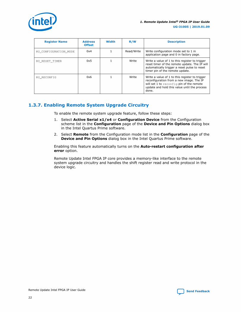
RU_CONFIGURATION_MODE 0x4 1 Read/Write Write configuration mode set to 1 inapplication page and 0 in factory page.
RU_RESET_TIMER 0x5 1 Write Write a value of 1 to this register to triggerreset timer of the remote update. The IP willautomatically trigger a reset pulse to resettimer pin of the remote update.
RU_RECONFIG 0x6 1 Write Write a value of 1 to this register to triggerreconfiguration from a new image. The IPwill set 1 to reconfig pin of the remoteupdate and hold this value until the processdone.
1.3.7. Enabling Remote System Upgrade Circuitry
To enable the remote system upgrade feature, follow these steps:
1. Select Active Serial x1/x4 or Configuration Device from the Configurationscheme list in the Configuration page of the Device and Pin Options dialog boxin the Intel Quartus Prime software.
2. Select Remote from the Configuration mode list in the Configuration page of theDevice and Pin Options dialog box in the Intel Quartus Prime software.
Enabling this feature automatically turns on the Auto-restart configuration aftererror option.
Remote Update Intel FPGA IP core provides a memory-like interface to the remotesystem upgrade circuitry and handles the shift register read and write protocol in the device logic.
1. Remote Update Intel® FPGA IP User Guide
UG-31005 | 2019.01.09
Remote Update Intel FPGA IP User Guide Send Feedback
22

1.4. Cyclone IV Devices
1.4.1. Remote System Configuration Mode
Remote Configuration Mode
Figure 10. Remote Configuration Mode
Power Up Set Control Registerand Reconfigure
Reload a Different Application
Reload a Different Application
Set Control Registerand Reconfigure
Configuration Error
Configuration Error
Configuration Error
Application 1Configuration
Application nConfiguration
FactoryConfiguration
(page 0)
Only Cyclone IV E devices support both the active parallel (AP) and active serial (AS)configuration scheme for remote system upgrade. Other Cyclone IV devices supportonly AS configuration scheme for remote system upgrade.
When using with EPCS or EPCQ devices, the remote update mode allows aconfiguration space to start at any flash sector boundary, allowing a maximum of 128pages in the EPCS64 device and 32 pages in the EPCS16 device, in which theminimum size of each page is 512 Kbits. Additionally, the remote update modefeatures a user watchdog timer that can detect functional errors in an applicationconfiguration.
1.4.2. Remote System Configuration Components
Table 13. Remote System Configuration Components in Cyclone IV Devices
Components Details
Page mode feature For both AS and AP configurations, Cyclone IV devices use a 24-bit boot start address inwhich you set the most significant 22 bits. Cyclone IV devices do not support pgmoutports.
Factory configuration Factory configuration is the default configuration setup.In remote configuration mode, the factory configuration loads into Cyclone IV devices uponpower-up.If a system encounters an error while loading application configuration data or if the devicereconfigures due to nCONFIG assertion, the device loads the factory configuration. Theremote system configuration register determines the reason for factory configuration.Based on this information, the factory configuration determines which applicationconfiguration to load.
continued...
1. Remote Update Intel® FPGA IP User Guide
UG-31005 | 2019.01.09
Send Feedback Remote Update Intel FPGA IP User Guide
23

Components Details
Upon power-up in remote update in the AP configuration scheme, Cyclone IV devices loadthe default factory configuration located at the following address:boot_address[23:0] = 24'h010000 = 24'b1 0000 0000 0000 0000.You can change the default factory configuration address to any address using theAPFC_BOOT_ADDR JTAG instruction. The factory image is stored in non-volatile memoryand is never updated or modified using remote access. This corresponds to the default startaddress location 0x010000 (or the updated address if the default address is changed) inthe supported parallel flash memory. Note that 0x010000 is the 16-bit word address forthe AP flash memory. However, the Intel Quartus Prime software implements 8-bit byteaddressing. Therefore, the correct Intel Quartus Prime software setting for this address is0x020000.
Application configuration The application configuration is the configuration data from a remote source and the data isstored in different locations or pages of the memory storage device, excluding the factorydefault page.
Watchdog timer A watchdog timer is a circuit that determines the functionality of another mechanism. Thewatchdog timer functions like a time delay relay that remains in the reset state while anapplication runs properly.The devices are equipped with a built-in watchdog timer for remote system configuration toprevent a faulty application configuration from indefinitely stalling the device.The timer is a 29-bit counter, but you use only the upper 12 bits to set the value for thewatchdog timer.The timer begins counting after the device goes into user mode. If the applicationconfiguration does not reset the user watchdog timer before time expires, the dedicatedcircuitry reconfigures the device with the factory configuration and resets the userwatchdog timer.To ensure the application configuration is valid, you must continuously reset the watchdogreset_timer within a specific duration during user mode operation.
Remote update sub-block The remote update sub-block manages the remote configuration feature. A remoteconfiguration state machine controls this sub-block. This sub-block generates the controlsignals required to control the various configuration registers.
Remote configurationregisters
The remote configuration registers keep track of page addresses and the cause ofconfiguration errors. You can control both the update and shift registers. The status andcontrol registers are controlled by internal logic, but are read via the shift register.The remote system upgrade status register has additional capabilities. Three sets ofregisters store the status for the current application configuration and the two previousapplication configurations.For details about configuration registers, refer to the Configuration, Design Security, andRemote System Upgrades chapter in the respective device handbook.
Related Information
Cyclone IV Device Handbook, Volume 1Provides more information about configuration registers of the Cyclone IV devices.
1. Remote Update Intel® FPGA IP User Guide
UG-31005 | 2019.01.09
Remote Update Intel FPGA IP User Guide Send Feedback
24

1.4.3. Parameter Settings
Table 14. Remote Update Intel FPGA IP core Parameters for Cyclone IV Devices
GUI Name Legal Value in GUI Description
Which operation modewill you be using?
REMOTE Specifies the configuration mode of the Remote UpdateIntel FPGA IP core.
Which configurationdevice will you beusing?
• EPCS device• EPCQ device
Choose the configuration device that you are using.
Add support forwriting configurationparameters
— Enable this if you need to write configurationparameters.
Enable reconfig POFchecking
— Allows you to enable .pof checking, which allows theremote update block to verify the existence of anapplication configuration image before the image isloaded. When you turn on this parameter, the RemoteUpdate Intel FPGA IP core checks the .pof and sends thereconfig signal. This option is disabled by default.
1.4.4. Ports
Table 15. Remote Update Intel FPGA IP Core Ports for Cyclone IV Devices
Name Port Required? Description
read_param Input No Read signal for the parameter specified in param[] inputport and fed to data_out[] output port.Signal indicating the parameter specified on the param[]port should be read. The number of bits set ondata_out[] depends on the parameter type. The signalis sampled at the rising clock edge. Assert the signal foronly one clock cycle to prevent the parameter from beingread again in a subsequent clock cycle.The busy signal is activated as soon as read_param isread as active. While the parameter is being read, thebusy signal remains asserted, and data_out[] hasinvalid data. When the busy signal is deactivated,data_out[] becomes valid and another parameter canbe read.
write_param Input No Write signal for parameter specified in param[] and withvalue specified in data_in[].Signal indicating parameter specified with param[]should be written into remote update block with the valuespecified in data_in[]. The number of bits read fromdata_in[] depends on the parameter type.The signal is sampled at the rising clock edge. The signalshould be asserted for only one clock cycle to prevent theparameter from being rewritten on a subsequent clockcycle. The busy signal is activated as soon aswrite_param is read as being active. While theparameter is being written, the busy signal remainsasserted, and input to data_in[] is ignored. When thebusy signal is deactivated, another parameter can bewritten. This signal is only valid in factory configurationmode because parameters cannot be written inapplication configuration mode.
param[] Input No Bus that specifies which parameter need to be read orupdated.
continued...
1. Remote Update Intel® FPGA IP User Guide
UG-31005 | 2019.01.09
Send Feedback Remote Update Intel FPGA IP User Guide
25

Name Port Required? Description
A 3-bit bus that selects the parameter to be read orupdated. If left unconnected, the default value for thisport is 000.For more information, refer to Parameters on page 28.
data_in[] Input No Data input for writing parameter data into the remoteupdate block. Input bus for parameter data.For some parameters, not all bits are used. In this case,the lower-order bits are used (for example, status valuesuse bits [4:0]).If left unconnected, this bus defaults to 0. The port isignored if the current configuration is the applicationconfiguration.For the Intel Quartus Prime software version 13.0 orearlier, the bus width is 22-bit. For the Intel QuartusPrime software version 13.1 and later, the bus widths areas follow:• 24-bit bus width—using 3-byte addressing
configuration device, for example EPCS128.• 32-bit bus width—using 4-byte addressing
configuration device, for example EPCQ256.
reconfig Input Yes Signal indicating that reconfiguration of the part shouldbegin using the current parameter settings. A value of 1indicates reconfiguration should begin. This signal isignored while busy is asserted to ensure all parametersare completely written before reconfiguration begins.
reset_timer Input No Reset signal for the watchdog timer.Signal indicating the internal watchdog timer should bereset. Unlike other inputs, this signal is not affected bythe busy signal and can reset the timer even when thebusy signal is asserted.A falling edge of this signal triggers a reset of the userwatchdog timer.For the timing specification of this parameter, refer to thespecific device handbook.
read_source Input Yes Specifies whether a parameter value is read from thecurrent or a previous state.This 2-bit port specifies the state from which a parametervalue is read. This signal is valid only when theread_param signal is valid.Mapping read_source[1..0] to Selected Source isdefined as follow:• 00 - Current State Content in Status Register• 01 - Previous State Register 1 Content in Status
Register• 10 - Previous State Register 2 Content in Status
Register• 11 - Value in Input RegisterFor details, refer to the Configuration, Design Security,and Remote System Upgrades chapter in the respectivedevice handbook.
clock Input Yes Clock input to the remote update block.Clock input to control the machine and to drive theremote update block during the update of parameters.This port must be connected to a valid clock.
reset Input Yes This is an active high signal. Asserting this signal high willreset the IP core.
continued...
1. Remote Update Intel® FPGA IP User Guide
UG-31005 | 2019.01.09
Remote Update Intel FPGA IP User Guide Send Feedback
26

Name Port Required? Description
Asynchronous reset input to the IP core to initialize themachine to a valid state. The machine must be resetbefore first use, otherwise the state is not guaranteed tobe valid.
busy Output No Busy signal that indicates when remote update block isreading or writing data.While this signal is asserted, the machine ignores most ofits inputs and cannot be altered until the machinedeasserts this signal. Therefore, changes are made onlywhen the machine is not busy.This signal goes high when read_param orwrite_param is asserted, and remains high until theread or write operation completes.
data_out[] Output No Data output when reading parameters.This bus holds read parameter data from the remoteupdate block. The param[] value specifies the parameterto read. When the read_param signal is asserted, theparameter value is loaded and driven on this bus. Data isvalid when the busy signal is deasserted.If left unconnected, the default value for the port is 000.The width of this bus is device-dependent:For the Intel Quartus Prime software version 13.0 orearlier, the bus width is 29-bit. For the Intel QuartusPrime software version 13.1 and later, the bus widths areas follow:• 29-bit bus width—using 3-byte addressing
configuration device, for example EPCS128.• 32-bit bus width—using 4-byte addressing
configuration device, for example EPCQ256.
asmi_busy Input No Input from the altasmi_parallel component.Available when the check_app_pof parameter is set totrue.A logic high on this pin indicates that the ASMI ParallelIntel FPGA IP core is busy processing the operation. TheRemote Update Intel FPGA IP core waits for this pin to golow before initiating another operation.Wire this pin to the asmi_busy output port of the ASMIParallel Intel FPGA IP core.
asmi_data_valid Input No Input from the altasmi_parallel component.Available when the check_app_pof parameter is set totrue.A logic high on this pin indicates valid data in theasmi_dataout[7..0] output port of the ASMI ParallelIntel FPGA IP core.Wire this pin to the asmi_data_valid output port of theASMI Parallel Intel FPGA IP core.
asmi_dataout Input No Input from the altasmi_parallel component.Available when the check_app_pof parameter is set totrue.The Remote Update Intel FPGA IP core presents theaddress information on this pin before initiating the readoperation on the ASMI Parallel Intel FPGA IP core.
pof_error Output No Detects an invalid application configuration image.Available when the check_app_pof parameter is set toTRUE.
continued...
1. Remote Update Intel® FPGA IP User Guide
UG-31005 | 2019.01.09
Send Feedback Remote Update Intel FPGA IP User Guide
27

Name Port Required? Description
A logic high on this pin indicates that the Remote UpdateIntel FPGA IP core detects an invalid applicationconfiguration image. If asserted high, you must takecorrective action by reloading a new applicationconfiguration image or specifying a different addresslocation in the EPCS or EPCQ that contains a validapplication configuration image. Wire this pin based onyour system requirement.
asmi_addr Output No Address signal to the altasmi_parallel component.Available when the check_app_pof parameter is set toTRUE. The Remote Update Intel FPGA IP core presentsthe address information on this pin before initiating theread operation on the ASMI Parallel Intel FPGA IP core.Wire this pin to the asmi_addr input port of the ASMIParallel Intel FPGA IP core.
asmi_read Output No Read signal to the altasmi_parallel component.Available when the check_app_pof parameter is set toTRUE. A logic high on this pin initiates the read operationon the ASMI Parallel Intel FPGA IP core.Wire this pin to the asmi_read input port of the ASMIParallel Intel FPGA IP core.
asmi_rden Output No Read enable signal to the altasmi_parallelcomponent.Available when the check_app_pof parameter is set toTRUE. This pin enables the read operation on the ASMIParallel Intel FPGA IP core.Wire this pin to the asmi_rden input port of the ASMIParallel Intel FPGA IP core.
1.4.5. Parameters
Table 16. Mapping to Each Parameter Type and Corresponding Parameter Bit Width forCyclone IV Devices
Bit Parameter Width Comments
000 Master State Machine CurrentState Mode (Read Only)
2 00—Factory mode.01—Application mode.11—Application mode with the master state machine userwatchdog timer enabled.
001 Force early CONF_DONE(cd_early) check
1 —
010 Watchdog Timeout Value 12 Width of 12 when writing.The 12 bits for writing are the upper 12 bits of the 29-bitWatchdog Timeout Value
29 Width of 29 when reading.
011 Watchdog Enable 1 —
continued...
1. Remote Update Intel® FPGA IP User Guide
UG-31005 | 2019.01.09
Remote Update Intel FPGA IP User Guide Send Feedback
28

Bit Parameter Width Comments
100 Boot Address — For the Intel Quartus Prime software version 13.1 and later:• Width of 29 or 32 when reading the boot address.• Width of 24 or 32 when writing the boot address.• For active serial devices using the 24-bit addressing, such as
EPCS128 or EPCQ128, boot_address[23..2] correspondsto the upper 22 bits of the 24-bits boot address.boot_address[1..0] is read as 2'b0.
• For active serial devices using the 32-bit addressing, such asEPCQ256, boot_address[31..2] corresponds to theupper 30 bits of the 32-bits boot address.boot_address[1..0] is read as 2'b0.
For the Intel Quartus Prime software version 13.0 or earlier:• Width of 24 when reading the boot address.• Width of 22 when writing the boot address.• Writes the boot address to the upper 22 bits of the 24-bits
boot address.
101 Illegal Value
110 Force the internal oscillator asstartup state machine clock(osc_int) option bit
1 —
111 Reconfiguration triggerconditions (Read Only)
5 Bit 4 (nconfig_source)—external configuration reset(nconfig) assertion.Bit 3 (crcerror_source)—CRC error during applicationconfiguration.Bit 2 (nstatus_source)—nstatus asserted by an externaldevice as the result of an error.Bit 1 (wdtimer_source)—User watchdog timer timeout.Bit 0 (runconfig_source)—Configuration reset triggered fromlogic array.
1.4.6. Remote Update Operation
The operation defined in the Remote Update Operation column should only beperformed in the corresponding master state machine (MSM) mode.
Table 17. Cyclone IV Devices Remote Update Operation
Note: read_source specifies whether a parameter value is read from the current or a previousstate. For more information, refer to Table 18 on page 31.
read_param
write_param
read_source param Remote Update Operation data_outwidth(bits)
MSM Mode
1 0 [00] [000] Master State Machine Current State Mode (ReadOnly)• 00—Factory mode• 01—Application mode• 11—Application mode with master state machine
user watchdog timer enabled
2 Factory orApplication
1 0 [00] [100] Read factory boot address 24 Factory
1 0 [01] [100] Read Past Status 1 boot address.For more information, refer to Figure 11 on page31.
24 Factory
continued...
1. Remote Update Intel® FPGA IP User Guide
UG-31005 | 2019.01.09
Send Feedback Remote Update Intel FPGA IP User Guide
29

read_param
write_param
read_source param Remote Update Operation data_outwidth(bits)
MSM Mode
1 0 [01] [111] Read Past Status 1 reconfiguration trigger conditionsource.For more information, refer to Figure 11 on page31.
5 Factory
1 0 [10] [100] Read Past Status 2 boot address.For more information, refer to Figure 11 on page31.
24 Factory
1 0 [10] [111] Read Past Status 2 reconfiguration trigger conditionsourceFor more information, refer to Figure 11 on page31.
5 Factory
1 0 [01] [010] Read current application mode watchdog value 29 Application
1 0 [01] [011] Read current application mode watchdog enable 1 Application
1 0 [10] [100] Read current application mode boot address 24 Application
0 1 [00] [001] Write the early confdone check bit.All parameters can be written in factory mode only.
1 Factory
0 1 [00] [010] Write the watchdog time-out value.All parameters can be written in factory mode only.
12 Factory
0 1 [00] [011] Write the watchdog enable bit.All parameters can be written in factory mode only.
1 Factory
0 1 [00] [100] Write application boot address.All parameters can be written in factory mode only.
22 Factory
0 1 [00] [110] Write to force the internal oscillator as startup statemachine clock. All parameters can be written infactory mode only.
1 Factory
1 0 [11] [001] Read the early confdone check bits 1 Factory
1 0 [11] [010] Read watchdog time-out value 12 Factory
1 0 [11] [011] Read watchdog enable bit 1 Factory
1 0 [11] [100] Read boot address 22 Factory
1 0 [11] [110] Read to check whether the internal oscillator is setas startup state machine clock
1 Factory
read_source
The following table lists the details for read_source. read_source specifieswhether a parameter value is read from the current or a previous state. When youtrigger the read operation, all contents in the status register or input register latchedto the data_out node in the Remote Update Intel FPGA IP core.
1. Remote Update Intel® FPGA IP User Guide
UG-31005 | 2019.01.09
Remote Update Intel FPGA IP User Guide Send Feedback
30

Table 18. read_source
read_source Description
00 Current state contents in status register
01 Previous state register 1 contents in status register
10 Previous state register 2 contents in status register
11 Current contents is in input register
State Register
The previous state register 1 reflects the current application configuration and theprevious state register 2 reflects the previous application configuration.
Figure 11. State Register
Application 1Configuration
Application 2Configuration
FactoryConfiguration
Configured the Application 1from Factory
Switched to Application 2
Back to factory(State register 1 reflects to current application which is application 1)
Back to factory(State register 1 reflects to current application which is application 2, whilethe state register 2 is reflects to previous application which is application 1)
1.4.7. Avalon-MM Interface
1.4.7.1. Control Status Register Signals
Table 19. Remote Update Intel FPGA IP Core Avalon-MM Control Status RegisterSignals for Cyclone IV Devices
Name Width Direction Description
clk 1 Input Clock input.
reset 1 Input Reset input.
continued...
1. Remote Update Intel® FPGA IP User Guide
UG-31005 | 2019.01.09
Send Feedback Remote Update Intel FPGA IP User Guide
31

Name Width Direction Description
avl_csr_address 3 Input Address bus.
avl_csr_read 1 Input Perform a read transaction.
avl_csr_write 1 Input Perform a write transaction.
avl_csr_readdata 32 Output Read data from IP.
avl_csr_readdata_valid 1 Output Indicate when read data is valid.
avl_csr_writedata 32 Input Write data to IP.
avl_csr_waitrequest 1 Output Waitrequest signal high indicates the core is busy.
1.4.7.1.1. Control Status Register Write Operation
To execute the write operation for the control status register, perform the followingsteps:
1. Asserts the avl_csr_write high.
2. Write a correct address of the register in the avl_csr_address bus. Refer to theRegister Map for register information.
3. Write data into the avl_csr_writedata bus.
Related Information
Register Map on page 33
1.4.7.1.2. Control Status Register Read Operation
To execute the read operation for the control status register, perform the followingsteps:
1. Asserts avl_csr_read signal high.
2. Write a correct address of the register in the avl_csr_address bus. Refer to theRegister Map for register information.
3. Wait for the avl_csr_readdata_valid signal to go high.
4. Retrieve read data from avl_csr_readdata.
1. Remote Update Intel® FPGA IP User Guide
UG-31005 | 2019.01.09
Remote Update Intel FPGA IP User Guide Send Feedback
32

1.4.7.2. Register Map
Table 20. Remote Update Intel FPGA IP Core Avalon-MM Register Map for Cyclone IVDevices• The last two bits of an address represents the read_source signals.
• You have to write the correct address offset to carry read_source value as shown in the Read SourceMapping table.
• The IP core combines the address bus of control status register interface to the read_source parameter.
• The default value for the registers is 0.
• The address offsets are in word.
Register Name AddressOffset
Width R/W Description
RU_MASTER_SM_CURRENT_STATE_MODE
0x0 2 Read Read current state of the state machine00: Factory mode01: Application mode11: Application mode with the master statemachine user watchdog timer enabled.
RU_FORCE_EARLY_CONF_DONE
0x4 1 Read/Write Force early CONF_DONE
RU_WATCHDOG_TIMEOUT 0x8 29 or 12 Read/Write Read or write watchdog timeout value.• 12 bit wide when writing• 29 bit wide when reading
RU_WATCHDOG_ENABLE 0xC 1 Read/Write Enable or disable watchdog timeout.• 0: Disable• 1: Enable
RU_BOOT_ADDRESS 0x10 24, 29 or 32 Read/Write • 29 or 32 bit wide (EPCQ 32 bitaddressing) when reading boot address.
• 24 or 32 bit wide when writing the bootaddress.
RU_FORCE_INTERNAL_OSC 0x14 1 Read/Write Force the internal oscillator as startup statemachine clock (osc_int) option bit
RU_RECONFIG_TRIGGER_CONDITIONS
0x18 5 Read Read configuration trigger conditions.
continued...
1. Remote Update Intel® FPGA IP User Guide
UG-31005 | 2019.01.09
Send Feedback Remote Update Intel FPGA IP User Guide
33
Register Name AddressOffset
Width R/W Description
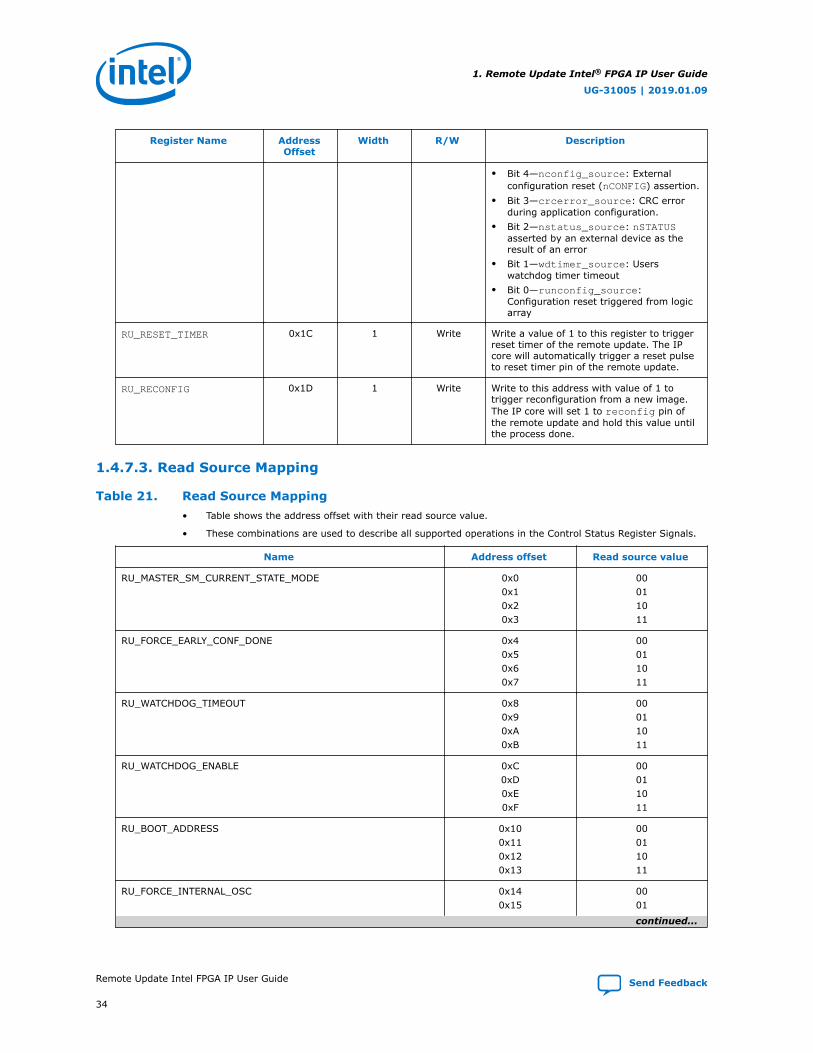
• Bit 4—nconfig_source: Externalconfiguration reset (nCONFIG) assertion.
• Bit 3—crcerror_source: CRC errorduring application configuration.
• Bit 2—nstatus_source: nSTATUSasserted by an external device as theresult of an error
• Bit 1—wdtimer_source: Userswatchdog timer timeout
• Bit 0—runconfig_source:Configuration reset triggered from logicarray
RU_RESET_TIMER 0x1C 1 Write Write a value of 1 to this register to triggerreset timer of the remote update. The IPcore will automatically trigger a reset pulseto reset timer pin of the remote update.
RU_RECONFIG 0x1D 1 Write Write to this address with value of 1 totrigger reconfiguration from a new image.The IP core will set 1 to reconfig pin ofthe remote update and hold this value untilthe process done.
1.4.7.3. Read Source Mapping
Table 21. Read Source Mapping• Table shows the address offset with their read source value.
• These combinations are used to describe all supported operations in the Control Status Register Signals.
Name Address offset Read source value
RU_MASTER_SM_CURRENT_STATE_MODE 0x00x10x20x3
00011011
RU_FORCE_EARLY_CONF_DONE 0x40x50x60x7
00011011
RU_WATCHDOG_TIMEOUT 0x80x90xA0xB
00011011
RU_WATCHDOG_ENABLE 0xC0xD0xE0xF
00011011
RU_BOOT_ADDRESS 0x100x110x120x13
00011011
RU_FORCE_INTERNAL_OSC 0x140x15
0001
continued...
1. Remote Update Intel® FPGA IP User Guide
UG-31005 | 2019.01.09
Remote Update Intel FPGA IP User Guide Send Feedback
34

Name Address offset Read source value
0x160x17
1011
RU_RECONFIG_TRIGGER_CONDITIONS 0x180x190x1A0x1B
00011011
RU_RESET_TIMER 0x1C N/A
RU_RECONFIG 0x1D N/A
1.4.8. Enabling Remote System Upgrade Circuitry
To enable remote update in the compiler settings of the project, perform the followingsteps:
1. On the Assignments menu, click Device.
2. In the Settings dialog box, Click Device and Pin Options.
3. In the Device and Pin Options dialog box , click the Configuration tab.
4. From the Configuration Mode list, select Remote.
5. Click OK.
6. In the Settings dialog box, click OK.
1.5. Flash Memory Programming Files
You can program the flash memory, EPCS, EPCQ, and EPCQ-L using the JTAG interfaceor Active Serial interface. Depending on the interface, you need to generate either aJTAG indirect configuration (.jic) file or a raw programming data (.rpd) file.
Table 22. Flash Memory Programming Files Based on Programming Interface
Programming Interface Flash MemoryProgramming File Used
Description
JTAG Interface .jic The .jic file instantiates the Serial Flash Loader IP core inthe design to form a bridge between the flash and the JTAGInterface.
Active Serial Interface .rpd Programming data is transferred directly between the flashand download cable.
To update the application image only, you can do either one of the following:
• Recompile the .jic file and choose new application image only in the convertprogramming file tool.
• Generate the .rpd file and program the EPCQ-L with ASMI IP or externalcontroller.
Related Information
• Using the Intel FPGA Serial Flash Loader with the Intel Quartus Prime Software
• ASMI Parallel Intel FPGA IP Core User Guide
1. Remote Update Intel® FPGA IP User Guide
UG-31005 | 2019.01.09
Send Feedback Remote Update Intel FPGA IP User Guide
35

1.6. Design Examples
1.6.1. Intel Arria 10 Remote Update Design Example
This Intel Arria 10 design example uses the Avalon-MM interface. Intel uses thefollowing hardware and software to create the design example:
• Intel Quartus Prime Version : 15.0
• Intel Arria 10 Development Kit with 10AX115S3F45I2SGE2 FPGA Device
Follow these steps to perform the design example tasks:
1. Unzip the contents of the design example to your working directory on your PC.
2. Convert the three .sof files into one .jic by using Convert Programming File.On the File Menu, click Convert Programming Files and select the details asshown below:
• Programming File type: JTAG Indirect Configuration File (.jic).
• Select Configuration Device: EPCQL1024.
• Mode: Active Serial.
• Set the file name you your desired location.
• Flash loader: click add device and choose 10AX115S2E2.
• SOFT DATA PAGE_0: click Add File and select the factory image with startaddress set to <auto>.
• SOFT DATA PAGE_1: click Add File and select the application image file withstart address 0x2000000. Compression is enabled for this application imagefile.
• SOFT DATA PAGE_2: click Add File and select the application image file withstart address 0x4000000. Compression is enabled for this application imagefile.
• Click Generate.
• Click OK when the dialog box of .jic file successfully generated appears.
3. Please follow the steps below to run the simple design:
a. After programming the .jic file, power cycle the board, all LED is lighted up.It indicates you are currently at factory image.
b. Go to system console and direct to the directory where yourFI_SysConsole_try.tcl is located. Type sourceFI_SysConsole_try.tcl.
Only one LED is lighted up which indicates successfully go to application image 1.After the watchdog timeout, all LED will light up and go back to factory image.
Note: To go to application image 2 directly form the factory image, comment outthe write boot address to App1 and uncomment the write bootaddress App2 in the FI_SysConsole_try.tcl file.
4. Setting Boot Page Selection for design with more than one SOF page:
a. To select the boot page, click the Option/Boot Info button in ConvertProgramming File.
1. Remote Update Intel® FPGA IP User Guide
UG-31005 | 2019.01.09
Remote Update Intel FPGA IP User Guide Send Feedback
36

b. In the Active Serial Boot Info window, select the page available from theBoot from page drop down menu. By default, the page number will be set atpage_0.
c. For application to application image, change the page number to page_1 orpage_2.
Related Information
Intel Arria 10 Remote System Update with Avalon-MM Interface Design Example
1.6.2. Cyclone V Remote Update Design Example
Intel uses the following hardware and software to create the design example:
• Intel Quartus Prime Version : 13.0
• Cyclone V Development Kit with 5CEFA7F31C7ES FPGA Device
Follow these steps to perform the design example tasks:
1. Unzip the contents of the design example to your working directory on your PC.
2. In the Intel Quartus Prime software, click Open Project in the File menu.
3. Compile the application image:
a. Browse to the folder in which you unzipped the files and open theApplication_Image.qpf.
b. Click Yes in the message box "Do you want to overwrite the database for C:/your working directory/Application_Image.qpf created by Quatus II 64-BitVersion 13.0.a Build 232 Service Pack 1 SJ Full version?"
c. On the Processing menu, choose Start Compilation.
d. Click OK when the full compilation successful dialog box appears. TheApplication_Image.sof will be generated in c:\your workingdirectory\output_files.
e. Click close project in the file menu.
4. Compile the factory image:
a. Browse to the folder in which you unzipped the files and open the SVRSU.qpf.
b. Click Yes in the message box "Do you want to overwrite the database for C:/your working directory/Application_Image.qpf created by QuatusII 64-Bit Version 13.0.a Build 232 Service Pack 1 SJ Full version?"
c. Choose Start Compilation on the Processing menu.
d. Click OK when the full compilation successful dialog box appears. TheFactory_Image.sof will be generated in c:\your working directory\output_files.
5. On the File Menu, click Convert Programming Files and select the details asshown below:
• Programming File type: JTAG Indirect Configuration File (.jic)
• Select Configuration Device: EPCQ 128
• Mode: Active Serial x4
• File name: c:/your working directory/output_file.jic
1. Remote Update Intel® FPGA IP User Guide
UG-31005 | 2019.01.09
Send Feedback Remote Update Intel FPGA IP User Guide
37

• Flash loader: click add device and choose 5CEFA7ES
• SOFT DATA PAGE_0: click Add File and select the factory image file(SVRSU.sof)
• SOFT DATA PAGE_1: click Add File and select the Application image file(Application_Image.sof)
• Click Generate.
• Click OK when the dialogue box of .jic file successfully generated appears.
6. On the Tool Menu, click Programmer and follow these steps:
a. Make sure the board is power up and the Intel FPGA Download Cable isconnected between computer and the board. This design example uses theIntel FPGA Download Cable and JTAG mode.
b. Click Auto Detect.
c. Right-click on the 5CEFA7ES and select change file.
d. Browse to the output_file.jic that was generated in previous steps.
e. Turn on the Program/Configure checkbox and click Start.
f. Configuration successful indicates the FPGA is configured successfully.
Related Information
• Cyclone V Remote System Update Design Example
• AN 603: Active Serial Remote System Upgrade Reference DesignProvides more information about Arria II GX, Stratix III and Stratix IV devicesreference design.
1.7. Remote Update Intel FPGA IP User Guide ArchivesIf an IP core version is not listed, the user guide for the previous IP core version applies.
IP Core Version User Guide
16.0 Altera Remote Update IP Core User Guide
15.1 Altera Remote Update IP Core User Guide
15.0 Altera Remote Update IP Core User Guide
14.0 Altera Remote Update IP Core User Guide
1.8. Document Revision History for the Remote Update Intel FPGAIP User Guide
Document Version Intel QuartusPrime Version
Changes
2019.01.09 18.0 • Updated the table description in Table: Remote Update Intel FPGA IPCore Avalon-MM Register Map for Cyclone IV Devices.
2018.11.26 18.0 • Renamed the document as Remote Update Intel FPGA IP User Guide.• Updated Figure: Typical Remote System Upgrade Process.• Updated the note under Figure: Typical Remote System Upgrade
Process.continued...
1. Remote Update Intel® FPGA IP User Guide
UG-31005 | 2019.01.09
Remote Update Intel FPGA IP User Guide Send Feedback
38

Document Version Intel QuartusPrime Version
Changes
• Added a note to Operations Example Waveforms.• Updated Table: Remote Update Intel FPGA IP Core Parameters for Intel
Arria 10 Devices to update the description for Enable reconfig POFchecking.
• Rebranded as Intel.
Table 23. Document Revision History
Date Version Changes
April 2017 2017.04.10 • Updated Transitions Between Factory and ApplicationConfigurations in Remote Update Mode figure.
• Removed redundant statement in Avalon-MM in Altera RemoteUpdate IP Core.
• Updated note in Remote Update Operation table.
October 2016 2016.10.31 • Updated Parameters table for Arria 10 devices and Arria II,Arria V, Cyclone V, Stratix IV, and Stratix V Devices.
• Added Add support for Avalon Interface parameter inParameter Settings tables.
June 2016 2016.06.01 • Updated Convert Programming File settings in Arria 10Remote Update Design Example.
• Removed references to Local update mode features.
May 2016 2016.05.02 • Added recommended FMAX for Altera Remote Update IP core.• Added missing title for Cyclone IV Devices Remote Update
Operation table.• Added note on possible PCIe timing violation when using direct-
to-application.• Added note on recommending user to set a fixed configuration
image start address.• Added Enabling Remote System Upgrade subsection.
December 2015 2015.12.14 Updated RU_RECONFIG_TRIGGER_CONDITIONS description forCyclone V Avalon-MM interface register.
November 2015 2015.11.17 • Updated Page description in Convert Programming Files settingfrom SOFT DATA PAGE_0 to SOFT DATA PAGE_1.
• Added high level configuration scheme block diagram forremote system upgrade.
• Added Flash Memory Programming Files.• Added design example for Arria 10 devices.
June 2015 2015.06.15 • Added Avalon-MM interface support for Quartus II Softwareversion 15.0.
• Added table for Avalon-MM interface Control Status Registersand register map definitions.
• Added steps for read and write operation for Avalon-MMinterface.
• Added example waveforms for read, write, reset timer,ctl_nupdt, and reconfiguration operation for Arria 10 devices.
• Updated the Device Support section to include information ondevice families that will be phased out from Quartus II softwareversion 15.0.
April 2015 2015.04.07 Added design example link.
January 2015 2015.01.23 Updated Arria 10 remote system configuration mode flow diagram.
continued...
1. Remote Update Intel® FPGA IP User Guide
UG-31005 | 2019.01.09
Send Feedback Remote Update Intel FPGA IP User Guide
39

Date Version Changes
December 2014 2014.12.15 • Updated POF checking feature description and invalidconfiguration image examples.
• Added Arria 10 device support with descriptions, ports andparameters.
• Replaced outdated design examples with a current applicationdesign example.
June 2014 2014.06.30 • Replaced MegaWizard Plug-In Manager information with IPCatalog.
• Added standard information about upgrading IP cores.• Added standard installation and licensing information.• Removed outdated device support level information. IP core
device support is now available in IP Catalog and parametereditor.
• Added a note to recommend users to use 20–MHz fMAX for alldevices.
May 2014 2014.05.13 • Updated the Device Support section to include information ondevice families that will be phased out from Quartus II softwareversion 13.1 and Quartus II software version 14.0.
• Rearranged content for remote system configuration modes,remote system configuration components, parameter settings,ports, param for each group of devices. Refer to Device Supportsection for more information.
August 2013 2013.08.16 Added Cyclone IV devices support for Active Serial RemoteConfiguration Mode in Parameters, Output Ports, and Active SerialRemote Configuration Mode.
July 2013 2013.07.12 • Updated Watchdog Timer to include the watchdog reset_timerequirement to ensure the validity of the applicationconfiguration. Listed the supported devices for the watchdogtimer feature.
• Updated Device Support section.• Added Active Serial Remote Configuration Mode to clarify that
the active serial configuration mode is a subset of the remoteconfiguration mode. Also clarified that this mode is onlyavailable for EPCS devices.
• Added a link to the Configuration Handbook in the RemoteSystem Configuration Modes.
• Updated Remote Configuration Mode to add that Cyclone IV Edevices support AP configuration scheme and included a link tothe Configuration and Remote System Upgrades in Cyclone IVDevices chapter.
• Updated Remote System Configuration Components to clarifythat the local configuration mode does not support the userwatchdog timer feature.
• Included a cross-reference to the Input Port in Page ModeFeature.
• Updated Parameters to update values and supported devices ofthe GUI parameter settings.
• Updated Factory Configuration to clarify that the default factoryconfiguration address does not apply for Cyclone V devices.
July 2013 2013.07.12 • Added Cyclone III and Cyclone IV Devices Remote UpdateOperation.
• Updated Input Ports to include Arria V and Cyclone V supportfor data_in[] port.
• Added Param[] as a standalone section.
continued...
1. Remote Update Intel® FPGA IP User Guide
UG-31005 | 2019.01.09
Remote Update Intel FPGA IP User Guide Send Feedback
40

Date Version Changes
• Updated Parameter Type and Corresponding Parameter BitWidth Mapping to include Arria V and Cyclone V support forReconfiguration trigger conditions parameter. Also updatedPage Select parameter to include information for Arria V,Cyclone V, and Stratix V devices.
• Updated Parameter Type and Corresponding Parameter BitWidth Mapping to update the Configuration Mode (AnF)information.
• Updated Input Ports to add a link to the Configuration, DesignSecurity, and Remote Upgrades in the Cyclone III Device Familychapter.
• Updated Input Ports to clarify that a falling edge of thereset_timer signal triggers a reset of the user watchdogtimer.
• Updated Output Ports to add Arria II, Arria V, Cyclone V, StratixIV, and Stratix V device support for 24-bit bus for data_out[]port.
• Added Knowledge Base section.• Added Simulation to clarify that simulation capability are for
Arria GX, Stratix, and Stratix II devices only.
February 2012 3.0 Add Cyclone IV support for param[] parameter.
August 2010 2.5 Updated for Quartus II software v10.0, including:• Updated the Device Family Support section.• Add Parameters table to Specifications chapter.• Added new parameters and ports to Specifications chapter.• Added new prototypes and declarations sections to
Specifications chapter.• Updated design example figures and steps.
April 2009 2.4 Updated for Quartus II software v9.0, including:• Updated the section.• Added the Maximum Clock Frequency (fMAX) for the supported
devices.• Updated ports and parameter tables.
May 2007 2.3 Updated for Quartus II software v7.1, including:• Updated to include support for Arria GX devices.• Updated to include Cyclone III device information.• Added Referenced Documents section.
March 2007 2.2 Updated Chapter 1 to include Cyclone III support.
December 2006 2.1 Updated Chapter 1 to include Stratix III support.
September 2006 2.0 General update for Quartus II software version 6.0, includingscreenshots; added ModelSim®-Altera simulation tool section toChapter 3.
March 2005 1.0 Initial release.
1. Remote Update Intel® FPGA IP User Guide
UG-31005 | 2019.01.09
Send Feedback Remote Update Intel FPGA IP User Guide
41