Remote Switcher Control Protocols - IP operation with the ...
68
Remote Switcher Control Protocols
Transcript of Remote Switcher Control Protocols - IP operation with the ...

Remote Switcher Control Protocols

Routing Switcher Protocols
Utah Scientific Inc. ii U.S.I. Part Number: 80101-0047 Version 1.5e
Remote Switcher Control Protocols Document Version: 1.5(e)
UTSCI Document Number: 80101-0047 Date: April 30, 2012 Printed in U.S.A.
Copyrights and Trademarks © 2012 Utah Scientific, Inc., All rights reserved. Any use or reproduction of this guide’s contents without the prior written consent of Utah Scientific, Inc. is strictly prohibited. Windows, Windows 2000 and Windows NT and XP are registered trademarks of Microsoft Corporation. All other product names and any registered or unregistered trademarks mentioned in this guide are used for identification purposes only and remain the exclusive property of their respective owners.
Notice Information contained in this guide is subject to change without notice or obligation. While every effort has been made to ensure that the information is accurate as of the publication date, Utah Scientific, Inc. assumes no liability for errors or omissions. In addition, Utah Scientific, Inc. assumes no responsibility for damages resulting from the use of this guide. FCC Compliance (USA) and Digital Equipment Compliance (Canada) This equipment has been tested and found to comply with the limits for a Class A, digital device, pursuant to Part 15, Subpart B of the FCC Rules and the Canadian EMC Requirement (ICES-003). These limits are designed to provide reasonable protection against harmful interference when the equipment is operated in a commercial environment. This equipment generates, uses, and can radiate radio frequency energy and, if not installed and used in accordance with the instruction manual, may cause harmful interference to radio communications. Operation of this equipment in a residential area is likely to cause harmful interference, in which case, the user will be required to correct the interference at their own expense. Shielded cables must be used to ensure compliance with the FCC Class A limits.

Routing Switcher Protocols
Utah Scientific Inc. iii U.S.I. Part Number: 80101-0047 Version 1.5e
Declaration of Conformity Utah Scientific, Inc. 4750 Wiley Post Way, Suite 150 Salt Lake City, Utah 84116-2878 U.S.A. We declare our sole responsibility that the Utah-400 Digital Routing Switcher is in conforMance with the following standards:
EN50081-1 Generic Emission Standard
EN50082-2 Generic Immunity Standard
IEC-950 Product Safety
C-UL 1950 Product Safety
UL 1950 Product Safety
Following the provisions of the Directive(s) of the Council of the European Union EMC Directive 89/336/EED
Low Voltage Electrical Directive 72/23/EEC
Utah Scientific, Inc. hereby declares that the product specified above conforms to the above Directive(s) and Standard(s).

Routing Switcher Protocols
Utah Scientific Inc. iv U.S.I. Part Number: 80101-0047 Version 1.5e
Important Safeguards and Notices This section provides important safety guidelines for the Operator and Service Personnel. Specific warnings and cautions are found throughout the guide where they apply, but may not appear here. Please read and follow the important safety information, specifically those instructions related to risk of fire, electric shock, or injury to persons.
Safety Symbols
Hazardous Voltage symbol
Caution symbol. The product is marked with this symbol when it is necessary to refer to the manual to prevent damage to the product.
Warnings Please observe the following important warnings:
Any instructions in this guide that require opening the chassis, changing a power supply, or removing a board, should be performed by qualified personnel only. To reduce the risk of electric shock, do not perform any service unless you are qualified to do so.
Heed all warnings on the unit and in the operating instructions.
Do not use this product in or near water. Disconnect AC power before installing any options or servicing the unit unless instructed to do so by this manual.
This product is grounded through the power cord ground conductor. To avoid electric shock, plug the power cord into a properly wired receptacle before connecting the product inputs or outputs.
Route power cords and other cables so they won’t be damaged.
The AC receptacle (socket) should be located near the equipment and be easily accessible.
Disconnect power before cleaning. Do not use any liquid or aerosol cleaner - use only a damp cloth.
Dangerous voltages exist at several points in this product. To avoid personal injury, do not touch exposed conductors and components while power is on.
Do not insert anything into either of the systems two-power supply cavities with power connected.

Routing Switcher Protocols
Utah Scientific Inc. v U.S.I. Part Number: 80101-0047 Version 1.5e
Do not wear hand jewellery or watches when troubleshooting high current circuits, such as power supplies. During installation, do not use the door handles or front panels to lift the equipment as they may open abruptly and injure you.
To avoid fire hazard when replacing fuses, use only the specified correct type, voltage and current rating as referenced in the appropriate parts list for this product. Always refer fuse replacement to qualified service personnel.
Have qualified personnel perform safety checks after any service.
Cautions Please observe the following important cautions:
When installing this equipment do not install power cords to building surfaces.
To prevent damage when replacing fuses, locate and correct the problem that caused the fuse to blow, before reconnecting power.
Use only specified replacement parts.
Company Information Utah Scientific, Incorporated 4750 Wiley Post Way, Suite 150 Salt Lake City, Utah 84116-2878 U.S.A.
Telephone: +1 (801) 575-8801
FAX: +1 (801) 537-3098
Technical Services (voice): +1 (800) 447-7204
Technical Services (FAX): +1 (801) 537-3069
E-Mail -General Information: [email protected]
E-Mail -Technical Services: [email protected]
World Wide Web: http://www.utahscientific.com
After Hours Emergency: +1 (800) 447-7204. Follow the menu instructions for Emergency Service.

Routing Switcher Protocols
Utah Scientific Inc. vi U.S.I. Part Number: 80101-0047 Version 1.5e
Table of Contents Communications Protocols......................................................................................1 Connecting to the Controller ..................................................................................2 RCP-1 Control Protocol...........................................................................................3 1.0 Overview ........................................................................................................3 1.1 Status Mode Configuration Commands ..................................................3 1.1.1 Matrix Refresh Report Enable................................................................4 1.1.2 Matrix Refresh Report Disable ..............................................................4 1.1.3 Matrix Change Report Enable................................................................5 1.1.4 Matrix Change Report Disable...............................................................5 1.1.5 Matrix Take Report Enable ....................................................................6 1.1.6 Matrix Take Report Disable ...................................................................7 1.1.7 Status Mode Configuration Command Summary .................................7 1.2 Matrix Control and Status .........................................................................8 1.2.1 Matrix Take Command...........................................................................9 1.2.2 Matrix Status Requests .........................................................................10 1.2.3 Matrix Command Summary .................................................................10 1.3 Miscellaneous System Status Requests...................................................11 1.3.1 Current Mode and Station Name Request ...........................................11 1.3.2 Program Checksum Request ................................................................12 1.3.3 Program Version Request .....................................................................12 1.4 Data Definitions .........................................................................................12 1.4.1 <Checksum>..........................................................................................12 1.4.2 <End Output>........................................................................................13 1.4.3 <Lev 1-4> ..............................................................................................13 1.4.4 <Lev 5-8> ..............................................................................................14 1.4.5 <Matrix Input> ......................................................................................14 1.4.6 <Matrix Output> ...................................................................................14 1.4.7 <Mode 1> ..............................................................................................15 1.4.8 <Mode 2> ..............................................................................................16 1.4.9 <ROM Checksum> ...............................................................................16 1.4.10 <Start Output>.....................................................................................16 1.4.11 <Station Name> ..................................................................................16 1.4.12 <Version>............................................................................................17 1.5 Command Code Summary .......................................................................17 RCP-2 Control Protocol.........................................................................................18 2.0 Overview .....................................................................................................18 2.0.1 How the RCP-2 Control Protocol Works ............................................18 2.1 Matrix Control and Status .......................................................................18 2.1.1 Matrix Take Command.........................................................................18

Routing Switcher Protocols
Utah Scientific Inc. vii U.S.I. Part Number: 80101-0047 Version 1.5e
2.1.2 Matrix Status Request ...........................................................................20

Routing Switcher Protocols
Utah Scientific Inc. viii U.S.I. Part Number: 80101-0047 Version 1.5e
RCP-3 Control Protocol.........................................................................................22 3.0 Overview ......................................................................................................22 3.0.1 RCP-3 and the Control System ............................................................22 3.0.2 How the RCP-3 Protocol Works ..........................................................22 3.0.3 Network Connections ...........................................................................23 3.0.4 Serial Connections ................................................................................23 3.0.5 Packet Format........................................................................................24 3.0.6 Packet Header Format...........................................................................24 3.0.7 Packet Data Format ...............................................................................25 3.0.8 Error Packet Format ..............................................................................25 3.1 Commands and Status ..............................................................................25 3.1.1 Command and Status Formats..............................................................25 3.2 Command Messages ..................................................................................26 3.2.1 Ping Command......................................................................................26 3.2.2 Verbosity Command .............................................................................26 3.2.3 Take Command .....................................................................................27 3.2.4 Attribute Command ..............................................................................27 3.2.5 Monitor Matrix Take Command ..........................................................28 3.2.6 Disconnect Command...........................................................................29 3.2.7 Salvo Command ....................................................................................29 3.2.8 Status Command ...................................................................................30 3.2.9 Get Matrix Command ...........................................................................30 3.2.10 Get Matrix Attributes Command .......................................................31 3.2.11 Get Monitor Matrix Command ..........................................................32 3.2.12 Set Lock Command ............................................................................32 3.2.13 Get Lock Command............................................................................33 3.2.14 Clear Lock Command.........................................................................34 3.2.15 Physical Disconnect Command..........................................................34 3.2.16 Command Code Summary .................................................................35 3.3 Extended Command Messages ................................................................36 3.3.1 Create AVS Command .........................................................................36 3.3.2 Get AVS Command ..............................................................................36 3.3.3 Destroy AVS Command .......................................................................37 3.3.4 Create UTAH Command ......................................................................37 3.3.5 Get UTAH Command...........................................................................38 3.3.6 Destroy UTAH Command....................................................................38 3.3.7 Create SCP Command ..........................................................................38 3.3.8 Get SCP Command ...............................................................................39 3.3.9 Destroy SCP Command........................................................................40 3.3.10 Mapping Command ............................................................................40 3.3.11 Get Mapping Command .....................................................................41 3.4 SCP Panel Command Messages ..............................................................42 3.4.1 Set Panel ID Command ........................................................................43 3.4.2 Get Panel ID Command........................................................................43 3.4.3 Set Source Group Name Command .....................................................43

Routing Switcher Protocols
Utah Scientific Inc. ix U.S.I. Part Number: 80101-0047 Version 1.5e
3.4.4 Get Source Group Name Command ....................................................44 3.4.5 Clear Source Group Name Command .................................................45 3.4.6 Set Destination Group Name Command .............................................45 3.4.7 Get Destination Group Name Command.............................................46 3.4.8 Clear Destination Group Name Command..........................................46 3.4.9 Set Source Name Command.................................................................47 3.4.10 Get Source Name Command..............................................................48 3.4.11 Clear Source Name Command...........................................................49 3.4.12 Set Destination Name Command.......................................................49 3.4.13 Get Destination Name Command ......................................................50 3.4.14 Clear Destination Name Command ...................................................51 3.4.15 End Programming Session Command ...............................................51 3.5 Status Messages..........................................................................................51 3.5.1 System Take Status ...............................................................................51 3.5.2 System Attribute Status ........................................................................52 3.5.3 System Monitor Matrix Take Status ....................................................52 3.5.4 System Lock Status...............................................................................53 3.5.5 Status Message Code Summary ...........................................................54 3.6 Error Status Formats ................................................................................54 3.6.1 Panel Error Status..................................................................................54 3.6.2 Error Status ............................................................................................55 3.6.3 Redundancy Error Status ......................................................................56 3.6.4 Watchdog Error Status..........................................................................57 3.6.5 General SC-3 Error Status ....................................................................57 Appendix ..................................................................................................................58
List of Tables Table 1: Protocols Supported by different Controllers......................................................... 1 Table 2: Command Code Summary ...................................................................................... 7 Table 3: Enabled Levels ......................................................................................................... 8 Table 4: Simple Matrix Take Command ............................................................................... 9 Table 5: Command Code Summary .................................................................................... 10 Table 6: RCP-1 Command Code Summary ........................................................................ 17 Table 7: RCP-3 Command Code Summary ........................................................................ 34 Table A1: ASCII Codes (Hexadecimal).............................................................................. 41 Table B1: RCP-1 Extended Command Code Summary..................................................... 47
List of Figures Figure 1.1: Connecting an ECD to the System Controller ................................................... 2

Routing Switcher Protocols Communications Protocol
1
Communications Protocols Local and Remote Control of a routing switcher matrix is provided by a system controller. External control of the routing switcher is provided generally by means of a serial RS-232 or RS-422 Interface using a specific set of commands defined in a Control Protocol. Successive generations of controllers have provided additional functionality and this has required extensions to the communications protocols or the development of new protocols. To provide backward compatibility with earlier versions of controllers, newer controllers commonly support use of both the old and the new protocols. This approach means that a developer who has interfaced to an earlier protocol will still be able to control a newer system without additional effort. Of course accessing the additional functionality provided by a new protocol will not be possible without interfacing to the new protocol. This document describes several control protocols supported by different controllers as indicated in the Table 1, below.
TABLE 1 Protocols Supported by Different Controllers
PROTOCOL SC1 SC2 SC3 SC4 FEATURES
RCP-1 √ √ √ Limited ASCII protocol providing basic router, multi-level control. Compatible with most UTAH controllers including the UDI-1B interface.
RCP-2 √ Binary protocol with low overhead. High speed single level control for real time applications like Master Control etc.
RCP-3 √ Ethernet only
Binary protocol providing the maximum amount of routing switcher control.
Choice of the control protocol used will depend upon the type of controller available, and the level of control needed.

Routing Switcher Protocols Communications Protocol
2
Connecting to the Controller The External Control Device (ECD) should be connected to the router system controller as shown in the figure below. The system controller processes commands from the ECD, translates them into appropriate crosspoint switch commands and transmits them to the matrix over the router control bus. This type of connection is convenient and has several significant advantages. • Complex Router Mappings are accommodated by the System Controller. • Tie Line Switching is accomplished by the System Controller. • Matrix Types can be made transparent to the ECD. • Additions to System Configurations can be made transparent to the ECD. • The router may operate with simultaneous control from ECD and dedicated control
panels.
ExternalControl Device
SystemController
RouterMatrix
FIGURE 1.1: Connecting an ECD to a System Controller.
The electrical connection between the ECD and the System Controller will be determined by the capabilities of both the ECD and the System Controller used. Each Routing Switcher Controller has unique interface requirements in terms of the type of electrical interface (RS-232, RS-422 ... ) and Data Rates. Please consult the technical manual for the particular controller to determine the interfaces supported by the controller.

Routing Switcher Protocols RCP-1 Protocol
3
RCP-1 Control Protocol
1.0 Overview The RCP-1 Control Protocol is a simple, 8 Level, ASCII Based Command Protocol used for sending commands to and receiving status from a Routing System Controller. There are three types of commands used by the external computer to communicate with the system controller: • Status Mode Configuration Commands. • Matrix Control and Matrix Status Request. • Miscellaneous System Status Requests. The external computer (ECD) initiates all commands and status requests. Each command begins with an ASCII control code (hex values 00 through 1F). If the system controller receives another ASCII control code while it is in the middle of a control message, the controller will abort the original message and begin receiving the new message immediately. A description of each command is provided in sections 1.2 through 1.4. Definitions of data formats are provided in Section 1.5. The SC-4 supports a limited version of this protocol. The status mode configuration commands are not supported and the status mode defaults to matrix change. Miscellaneous system status requests are not enabled. Requests for status are limited to the ESC-L style requests. Matrix control and status are supported as documented hereafter. NOTE: 1. In the following sections, optional variables are enclosed within vertical bars, as in
|<Checksum>|. 2. Unless otherwise specified, all ASCII values are in hexadecimal. 3. ASCII control codes such as STX, SOH and VT are used in these protocols. A table
listing the ASCII codes is included in the appendix.
1.1 Status Mode Configuration Commands The system controller can be set to automatically update the ECD with matrix status in several different ways: • Matrix Refresh.
Automatic Status Reporting of the entire matrix. • Matrix Change.
Automatic Status Reporting when the matrix status changes. • Matrix Take.
Automatic Status Reporting whenever a Take is made. It is possible to have any combination of these modes active simultaneously, although typically only one of these is active at a time. Status Information is provided by the controller to the ECD as soon as the information is available and without any specific

Routing Switcher Protocols RCP-1 Protocol
4
request by the ECD. In addition the ECD can specifically request status for an individual output by using the MATRIX STATUS REQUEST command detailed in Section 1.3. Each status mode configuration command is two ASCII characters in length, consisting of the ESCape Code followed by a Mode Enable or Mode Disable Code. A Summary Table of Mode Configuration Commands is shown in Section 1.2.7.
1.1.1 Matrix Refresh Report Enable
ASCII CODE HEX
Command Code: ESC @ 1B, 40
Response: None
The System Controller is responsible for storing the matrix status, and routinely updates the matrix with this data to ensure the integrity of status in the matrix. In the event that a board is replaced in the matrix, the original state of the crosspoints will be assured without manual intervention. This process of continually updating the matrix is known as a refresh cycle. This same process can be provided to the ECD by enabling the Matrix Refresh Report function. The ESC @ sequence causes the System Controller to routinely report this information to the external computer. Refresh data is provided on an unsolicited basis with the data format as follows: STX <Lev 1-4> <Lev 5-8> <Matrix Input> <Matrix Output> <Checksum> CR
Related Commands: MATRIX REFRESH REPORT DISABLE
1.1.2 Matrix Refresh Report Disable
ASCII CODE HEX
Command Code: ESC A 1B, 41
Response: None
Matrix Refresh reporting is described in the previous section. To disable the function, the Matrix Refresh Report Disable Command is provided. Issuing the command string ESC A will disable Matrix Refresh Reporting. Related Commands: MATRIX REFRESH REPORT ENABLE

Routing Switcher Protocols RCP-1 Protocol
5
1.1.3 Matrix Change Report Enable
ASCII CODE HEX
Command Code: ESC B 1B, 42
Response: None
The Matrix Change Report Function causes the controller to issue a Status Update to the ECD whenever a change occurs in the Matrix Status. A change in status occurs when a Take is made resulting in a change to the status of the matrix. If a Take is made to a destination requesting the same sources that is already selected, then this will not cause a change in status, and consequently this will not be reported to the ECD. The system controller reports the status of all levels on the changed output, even if only one level actually changed. NOTE: 1. The Matrix Change Report is output oriented and issues status reporting relating to
actual matrix changes issued by the controller, to the matrix, as opposed to the actual changes requested. Consequently if a panel or external controller requests an invalid selection this will not be reported
2. The RCP-1 Protocol is centered around Partyline Control. Some System Controllers support additional control panel protocols. If the panel mapping for the additional protocols overlaps the Partyline mapping, then for the overlapped area, the change information from either type of panel will be properly reported.
3. The result of a SALVO Take will not be reported, unless a U-NET Protocol Panel initiated it and the panel was mapped into the same router space as Partyline Panels.
The ESC B Sequence causes the System Controller to enable the Matrix Change Reporting Function. Until the function is disabled, the controller will report changes in status without further request from the ECD. The change report data format is as follows: FS <Lev 1-4> <Lev 5-8> <Matrix Input> <Matrix Output> <Checksum> CR
Related Commands: MATRIX CHANGE REPORT DISABLE
1.1.4 Matrix Change Report Disable
ASCII CODE HEX
Command Code: ESC C 1B, 43
Response: None
Matrix Change Reporting is described in detail in the previous section. The ESC C Command sequence disables the Matrix Change Reporting Function. Related commands:

Routing Switcher Protocols RCP-1 Protocol
6
MATRIX CHANGE REPORT ENABLE
1.1.5 Matrix Take Report Enable
ASCII CODE HEX
Command Code: ESC D 1B, 44
Response: None
The Matrix Take Report Function causes the controller to issue a status update to the ECD, whenever a Take occurs, regardless of whether the Take changes the state of the matrix. The System Controller reports the status of all levels on the changed output. NOTE: 1. The RCP-1 Protocol is centered around Partyline Control. Some System
Controllers support additional control panel protocols. If the panel mapping for the additional protocols overlaps the Partyline mapping then the change information from either type of panel will be properly reported.
2. Takes initiated by Partyline Panels and serial ports will be reported regardless of mapping.
3. The Matrix TAKE Report is effectively input oriented and responds with a report to requested changes regardless of validity.
4. If a Take is made to a destination, requesting the same sources that are already selected, this will be reported to the ECD.
5. A SALVO Take will be reported only as a SALVO. The results of the SALVO in terms of matrix changes will not be reported.
The ESC D sequence causes the system controller to report any change in router matrix status (Take Reporting) to the ECD. The Matrix Take Report format is as follows: SOH <Lev 1-4> <Lev 5-8> <Matrix Input> <Matrix Output> <Checksum> CR Related Commands: MATRIX TAKE REPORT DISABLE

Routing Switcher Protocols RCP-1 Protocol
7
1.1.6 Matrix Take Report Disable
ASCII CODE HEX
Command Code: ESC E 1B, 45
Response: None
The Matrix Take Report is described in detail in the previous section. The ESC E command sequence disables the Take reporting function. Related commands: MATRIX TAKE REPORT ENABLE
1.1.7 Status Mode Configuration Command Summary The following table provides a summary of the commands described in the previous parts of this section.
Table 2: Command / Code Summary ASCII HEX Command Protocol / Comments ESC @ 1B 40 Matrix Refresh Report enable.
Reported data = STX <Lev 1-4><Lev 5-8> <Matrix input> <Matrix output> <Checksum> CR
ESC A 1B 41 Matrix Refresh Report disable.
ESC B 1B 42 Matrix Change Report enable. Reported data = FS <Lev 1-4> <Lev 5-8> <Matrix input> <Matrix output> <Checksum> CR
ESC C 1B 43 Matrix Change Report disable.
ESC D 1B 44 Matrix Take Report enable. Reported data = SOH<Lev 1-4> <Lev 5-8> <Matrix input> <Matrix output><Checksum> CR
ESC E 1B 45 Matrix Take Report Disable.

Routing Switcher Protocols RCP-1 Protocol
8
1.2 Matrix Control and Status The ECD can switch matrix outputs by issuing commands to the system controller, as well as recalling the current matrix status from the system controller. Each cross point effectively has an address that is related to the electrical location in the matrix. For example, to select a particular cross point it is necessary to define the Input Number, Output (or bus) Number and the Matrix Level (a numeric value associated generally with the signal type - video, audio, etc.). A SINGLE TAKE command may need to select the same input to several levels at the same time and to support this capability, the levels are bit mapped into 2 characters. Each character represents 4 levels as shown in Table 1.3-1 below.
Table 3: Enabled Levels First Character Second Character
ASCII Levels Enabled ASCII Levels Enabled Character 4 3 2 1 Character 8 7 6 5
@ @
A x A x
B x B x
C x x C x x
D x D x
E x x E x x
F x x F x x
G x x x G x x x
H x H x
I x x I x x
J x x J x x
K x x x K x x x
L x x L x x
M x x x M x x x
N x x x N x x x
O x x x x O x x x x

Routing Switcher Protocols RCP-1 Protocol
9
1.2.1 Matrix Take Command
ASCII CODE HEX
Command Code: SOH 01
Response: None
Making a selection on the Routing Switcher Matrix is known as making a Take. Switcher cross points are changed by using the Matrix Take Command. The Matrix Level, Input Number and Output Number identify each cross point. (Level mapping is shown in Table 1.3-1). The command message is structured as follows: SOH <Lev 1-4> <Lev 5-8> <Matrix Input> <Matrix Output> |<Checksum>| or |CR| To generate a Matrix Take Command, issue the command SOH followed by the code for enabled levels 1-4, enabled levels 5-8, input and output selection and terminated by either the optional checksum or carriage return (C/R). The following example, shown in Table 1.3-2 below, uses the Matrix Take Command to select input 45 to output 123 on levels 1, 2, 3, 4 and 7.
Table 4: Sample Matrix Take Command
Take Command
Levels 1 - 4
Levels 5 - 8
Input Number
Output Number
C/R or Opt. Checksum
Symbol SOH O D 0 4 5 1 2 3 C/R
HEX 01 4F 44 30,34,35 31,32,33 0D
NOTE: Levels not included in the Take command will remain in the same state as before the Take command was issued. Breakaway switching requires an additional Take command for each level that is switched independently. Related commands: MATRIX STATUS REQUEST

Routing Switcher Protocols RCP-1 Protocol
10
1.2.2 Matrix Status Requests
ASCII CODE HEX
Command Code: ESC L <Start Output> <End Output>
1B, 4C <Start Output> <End Output>
Response: STX <Lev 1-4> <Lev 5-8> <Matrix Input> <Matrix Output> <Checksum> CR
02, <Lev 1-4> <Lev 5-8> <Matrix Input> <Matrix Output> <Checksum> CR
The Matrix Status Request Command provides the External Control Device (ECD) with the facility to establish the current status of any specific output or block of outputs in the matrix. For a block of outputs the following command sequence should be used: ESC L <Start Output> <End Output>
The controller will respond with a report consisting of a sequence of status messages ordered by output number, with each message formatted as follows: STX <Lev 1-4> <Lev 5-8> <Matrix Input> <Matrix Output> <Checksum> CR
The report is terminated by the system controller with the ASCII Code US (Hex 1F). To obtain Status of a Single Matrix Output, the command string should be terminated with a CR immediately following the starting matrix output number: ESC L <Start Output> CR The controller will respond with a single status message formatted as follows: STX <Lev 1-4> <Lev 5-8> <Matrix Input> <Matrix Output> <Checksum> CR
Related commands: MATRIX TAKE COMMAND
1.2.3 Matrix Command Summary The Matrix Command Codes are summarized in the TABLE 5, below:
Table 5: Command Code Summary ASCII HEX Command Protocol / Comments ESC L 1B 4C Matrix Status Request.
ESC L <Start Output> <End Output> Reported data = STX <Lev 1-4> <Lev 5-8> <Matrix input><Matrix output> <Checksum> CR
SOH 01 Matrix Take command. <Lev 1-4> <Lev 5-8> <Matrix input> <Matrix output> |<Checksum>| or |CR|

Routing Switcher Protocols RCP-1 Protocol
11
1.3 Miscellaneous System Status Requests This section details several miscellaneous system status requests allowing the external device to request information such as system software version.
1.3.1 Current Mode and Station Name Request
ASCII CODE HEX
Command Code: ESC 0 1B,4F
Response: HT <Mode 1> <Mode 2> <Space> <Station Name> <P/L Status> <Checksum> CR
09, <Mode 1> <Mode 2> <Space> <Station Name> <P/L Status> <Checksum> CR
When the System Controller receives this code sequence, it responds with the current mode and station name (see notes below). The format of the response is as follows: HT <Mode 1> <Mode 2> <Space> <Station Name> <P/L Status> <Checksum> CR
NOTE:
1. Mode 1 and Mode 2 are described in section 1.5 2. Station Name has a meaningful value only in context of a Partyline device such as
the UDI -1B interface. In the case of the SC-3 controller, the Station name field is filled by the dummy station name 7F.
3. The SC-3 controller does not support P/L Status. For other devices the ASCII character returned is 1 when the Party Line is up and 0 when the Party Line is down.
1.3.2 Program Checksum Request
ASCII CODE HEX
Command Code: ESC P 1B,50
Response: VT <Space> <ROM Checksum> <Space> <Checksum> CR
0B <Space> <ROM Checksum> <Space> <Checksum> CR
Use this code sequence to request the checksum value of the Program EPROM. The system controller returns the following information:

Routing Switcher Protocols RCP-1 Protocol
12
VT <Space> <ROM Checksum> <Space> <Checksum> CR
1.3.3 Program Version Request
ASCII CODE HEX
Command Code: ESC V 1B,56
Response: BS <Version> <Checksum> CR
08 <Version> <Checksum> CR
Use this sequence to determine the System Controller’s Program Version. When the system controller receives this command, it responds as follows: BS <Version> <Checksum> CR
1.4 Data Definitions This section provides definitions of data types used in both the command and status messages.
1.4.1 <Checksum> A single-byte checksum in the range 20 hex through 7F hex calculated as follows:
Start with the hexadecimal value of the first byte (control code).
To that value, Exclusive OR the second byte, Exclusive OR the third byte, etc. until all bytes have been Exclusive OR’ed.
Finally, OR a hexadecimal 20 to the final Exclusive Or’ed value of all the bytes. By OR’ing in the 20 you ensure that the checksum is greater than or equal to a hexadecimal 20. This must be done to ensure an ASCII Control Code is NOT generated as the checksum.
1.4.2 <End Output> This is a three-byte matrix output number used in multiple status requests.
See <Matrix Output>.

Routing Switcher Protocols RCP-1 Protocol
13
1.4.3 <Lev 1-4> A single ASCII character symbol (@ through to the letter O) that represents the levels (from 1 through 4) to which a take or status word applies. The four levels are bit mapped into the ASCII character as shown in the table below:
LEVEL SELECTION
LEVEL CHAR
ENABLED LEVELS
4 3 2 1
@
A x
B x
C x x
D x
E x x
F x x
G x x x
H x
I x x
J x x
K x x x
L x x
M x x x
N x x x
O x x x x
The other four levels (5-8) are bit mapped into a character in the same way as detailed in the following section.

Routing Switcher Protocols RCP-1 Protocol
14
1.4.4 <Lev 5-8> A single character that represents the levels (from 5 through 8) to which a take or status word applies. The four levels are bit mapped into the ASCII character as shown in the Table below:
LEVEL SELECTION
LEVEL ENABLED LEVELS CHAR 8 7 6 5
@
A x
B x
C x x
D x
E x x
F x x
G x x x
H x
I x x
J x x
K x x x
L x x
M x x x
N x x x
O x x x x
1.4.5 <Matrix Input> A three-ASCII character matrix input number from 000 through 319. Leading zeros must be inserted for values less than 100 (e.g., matrix input number 5 equals 005).
NOTE: This is a 3 character ASCII string, not a binary number.
1.4.6 <Matrix Output> A three-ASCII character matrix output number from 000 through 319. Leading zeros must be inserted for values less than 100 (e.g. matrix output number 5 equals 005).
NOTE: This is a 3 character ASCII string, not a binary number.
Routing Switcher Protocols RCP-1 Protocol
15
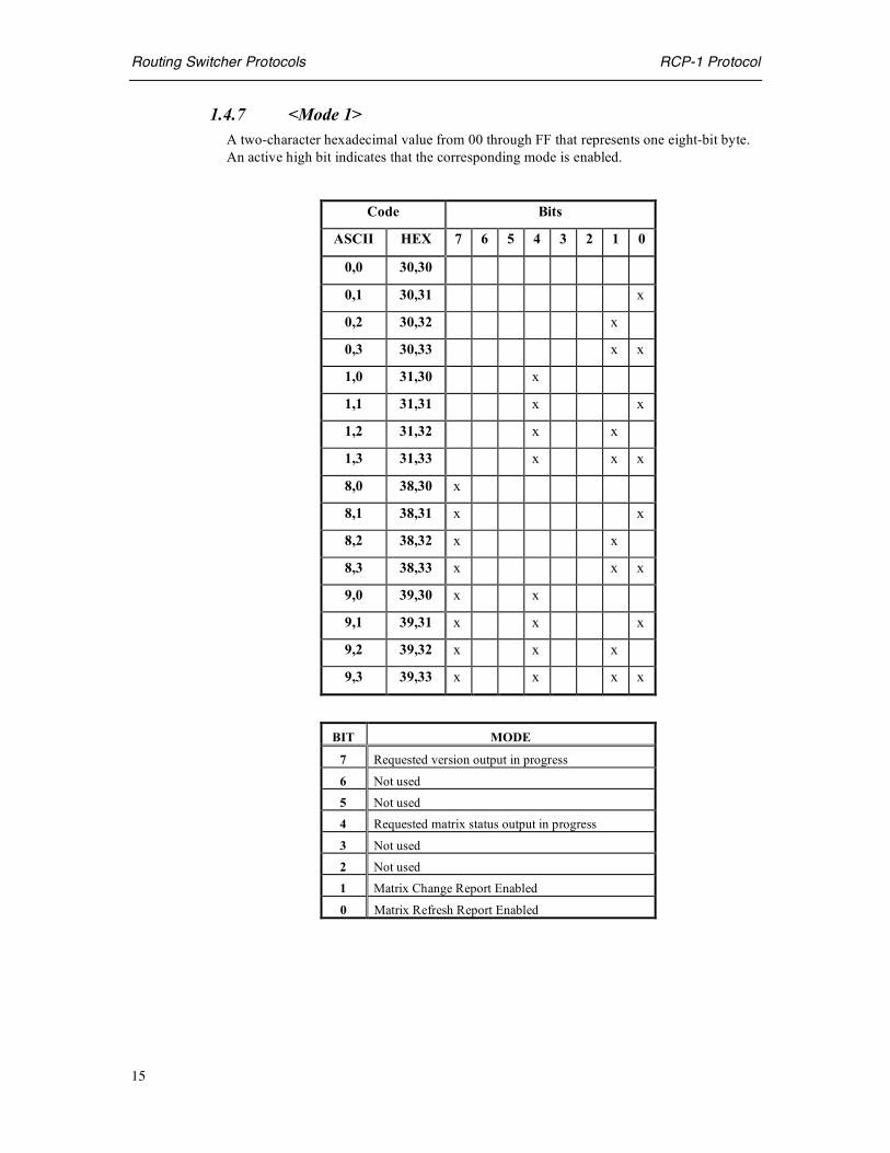
1.4.7 <Mode 1> A two-character hexadecimal value from 00 through FF that represents one eight-bit byte. An active high bit indicates that the corresponding mode is enabled.
Code Bits
ASCII HEX 7 6 5 4 3 2 1 0
0,0 30,30
0,1 30,31 x
0,2 30,32 x
0,3 30,33 x x
1,0 31,30 x
1,1 31,31 x x
1,2 31,32 x x
1,3 31,33 x x x
8,0 38,30 x
8,1 38,31 x x
8,2 38,32 x x
8,3 38,33 x x x
9,0 39,30 x x
9,1 39,31 x x x
9,2 39,32 x x x
9,3 39,33 x x x x
BIT MODE
7 Requested version output in progress
6 Not used
5 Not used
4 Requested matrix status output in progress
3 Not used
2 Not used
1 Matrix Change Report Enabled
0 Matrix Refresh Report Enabled
Routing Switcher Protocols RCP-1 Protocol
16
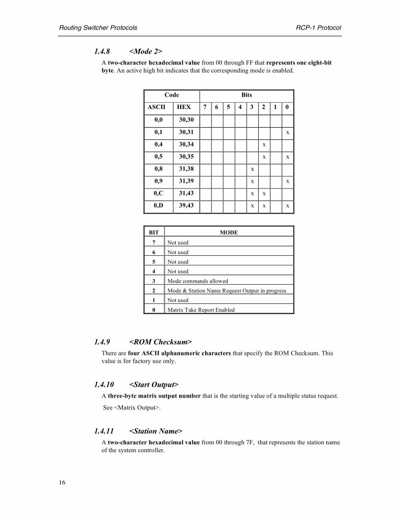
1.4.8 <Mode 2> A two-character hexadecimal value from 00 through FF that represents one eight-bit byte. An active high bit indicates that the corresponding mode is enabled.
Code Bits
ASCII HEX 7 6 5 4 3 2 1 0
0,0 30,30
0,1 30,31 x
0,4 30,34 x
0,5 30,35 x x
0,8 31,38 x
0,9 31,39 x x
0,C 31,43 x x
0,D 39,43 x x x
BIT MODE
7 Not used
6 Not used
5 Not used
4 Not used
3 Mode commands allowed
2 Mode & Station Name Request Output in progress
1 Not used
0 Matrix Take Report Enabled
1.4.9 <ROM Checksum> There are four ASCII alphanumeric characters that specify the ROM Checksum. This value is for factory use only.
1.4.10 <Start Output> A three-byte matrix output number that is the starting value of a multiple status request.
See <Matrix Output>.
1.4.11 <Station Name> A two-character hexadecimal value from 00 through 7F, that represents the station name of the system controller.

Routing Switcher Protocols RCP-1 Protocol
17
1.4.12 <Version> Eight ASCII alphanumeric characters that specify the current system controller software version.
NOTE:
• The SC3 system controller returns the string “SC3SW1.0”
1.5 Command Code Summary
Table 6: RCP-1 COMMAND CODE SUMMARY ASCII HEX Command Protocol / Comments
SOH 01 Matrix Take Command. SOH <Lev 1-4> <Lev 5-8> <Matrix input> <Matrix output>|<Checksum> | or |CR|
ESC @ 1B 40 Matrix Refresh Report Enable. Reported data = STX <Lev 1-4><Lev 5-8> <Matrix input> <Matrix output> <Checksum> CR
ESC A 1B 41 Matrix Refresh Report Disable
ESC B 1B 42 Matrix Change Report Enable. Reported data = FS <Lev 1-4> <Lev 5-8> <Matrix input> <Matrix output> <Checksum> CR
ESC C 1B 43 Matrix Change Report Disable
ESC D 1B 44 Matrix Original Take Report Enable. Reported data = SOH<Lev 1-4> <Lev 5-8> <Matrix input> <Matrix output><Checksum> CR
ESC E 1B 45 Matrix Original Take Report Disable.
ESC L 1B 4C Matrix Status Request Reported data = STX <Lev 1-4> <Lev 5-8> <Matrix input><Matrix output> <Checksum> CR
ESC 0 1B 4F Current Mode and Station Name Request. Reported data = HT <Mode 1> <Mode 2> <Space> <Station name> <P/L status> <Checksum> CR
ESC P 1B 50 Program Checksum Request. Reported data = VT <Space><ROM checksum> <Space> <Checksum> CR.
ESC V 1B 56 Program Version Request. Reported data = BS <Version><Checksum> CR

Routing Switcher Protocols RCP-2 Protocol
18
RCP-2 Control Protocol
2.0 Overview The RCP-2 Control Protocol is a basic router control protocol optimized for applications where real time switching over a serial interface is the primary requirement. The protocol is binary based allowing the External Controlling Device (ECD) to set crosspoints and query the matrix (crosspoint) status. A typical application requiring this type of interface is control from a Master Control Switcher.
2.0.1 How the RCP-2 Control Protocol works This protocol is very elementary, supporting only 2 commands. The ECD can transmit several TAKE commands selecting sources for up to 24 outputs in a single field. To maximize the available communications bandwidth, the controller does not echo or confirm takes in response to a TAKE command. The protocol supports the ability for the ECD to query the controller to determine the state of each output. A series of requests can be sent as a sequence, and the controller will perform operation in the same order as received.
2.1 Matrix Control and Status This section lists the command and status data formats for the RCP-2 Control Protocol. There are only two commands available, supporting the basic requirement to select sources to destinations, and determine the current selection for each output. The protocol allows selection of up to 64 Destinations, and up to 128 Sources. Individual levels cannot be directly addressed without appropriate matrix mapping. The ECD can switch matrix outputs by issuing commands to the system controller as well as recalling the current matrix status from the system controller by use of the 2 commands described in the following sections.
2.1.1 Matrix Take Command Making a selection on the Routing Switcher Matrix is known as making a TAKE. This is accomplished by the ECD using the Matrix Take command. Although Level addressing is not supported by the protocol, and All Level Follow does not require levels to be individually addressed. By appropriately setting up the router controller it is possible to make All Level TAKES on a multiple level router. Additionally, the Breakaway TAKE functionality can be provided in the controller by offsetting physical router outputs on different levels enabling the protocol to uniquely address router levels as if they are an extension of a single level. The Take Command is a 2-byte word containing the destination and source data. The MSB of the first word is used to indicate whether the command is a Take or Status command. The bit is set high for a Take command and is low for a Status command. As a result the first byte of the Take command is 80 hex + output number (0-3F hex, 0-63 decimal). The second byte of the Take command includes a 7-bit source address as shown in the following table:

Routing Switcher Protocols RCP-2 Protocol
19
Byte BINARY COMMENTS
1 Command code: 10dddddd dddddd represents the 6 bit destination value. 2 Source: 0sssssss sssssss represents the 7 bit source value
Response: None Use matrix status to confirm TAKE
The following figure shows the bit mapping used in the first byte of the Take command word.
TAKE DESTINATION BYTE BIT VALUE
7 Set to 1
6 Set to 0
5 Destination address bit 5
4 Destination address bit 4
3 Destination address bit 3
2 Destination address bit 2
1 Destination address bit 1
0 Destination address bit 0
The following figure shows the bit mapping of the second byte of the Take command word.
TAKE SOURCE BYTE BIT VALUE
7 Set to 0
6 Source address bit 6
5 Source address bit 5
4 Source address bit 4
3 Source address bit 3
2 Source address bit 2
1 Source address bit 1
0 Source address bit 0
NOTE: 1. The controller does not acknowledge a TAKE, whether successful or not (Use
Matrix Status Request if confirmation is required). 2. The protocol supports a maximum destination range of 0-63 and source range of 0-
127. Mapping in the routing controller can be used to allow the ECD to access destinations and sources outside of this range. For example, it is possible to address the matrix destinations 128 - 191 by offsetting the destinations in the controller by a factor of 128.
3. Multiple Take commands can be transmitted sequentially.

Routing Switcher Protocols RCP-2 Protocol
20
4. By configuring different physical levels (video and audio for example) to the same level address and offsetting the destinations for audio and video it is possible to support the breakaway TAKE capability.
Example: To satisfy the following requirements:
• Select source number 29 on destination 14. The ECD would issue the following message (hexadecimal notation)
• 9D, 0E Related commands: MATRIX STATUS REQUEST
2.1.2 Matrix Status Request The Matrix Status Request command provides the external control device (ECD) with the facility to establish the current status of any specific output. The Matrix Status Request is a single byte word. The highest order bit of the first byte is set to 0 to indicate that the command is a Status Request, and the lowest 6 bits of the word contain a 6 bit destination address.
BINARY COMMENTS
Command Code: 00dddddd dddddd represents the 6 bit destination value. Response: 0sssssss sssssss represents the 7 bit source value
Multiple Matrix Status Request Commands can be transmitted sequentially so the external control device (ECD) can query the status of several outputs in the same field without waiting for a response for each individual status request. The bit mapping used in the Matrix Request Status command word is shown in the following table.
STATUS REQUEST COMMAND BIT VALUE
7 Set to 0
6 Set to 0
5 Destination address bit 5
4 Destination address bit 4
3 Destination address bit 3
2 Destination address bit 2
1 Destination address bit 1
0 Destination address bit 0
Routing Switcher Protocols RCP-2 Protocol
21
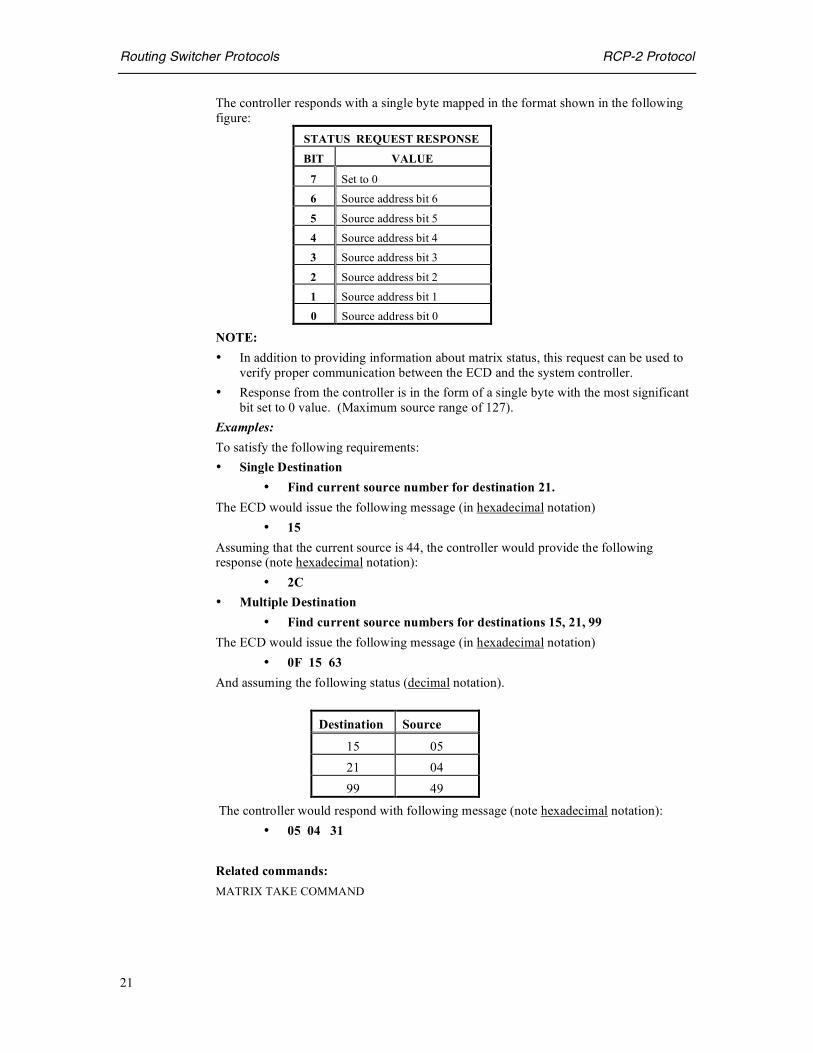
The controller responds with a single byte mapped in the format shown in the following figure:
STATUS REQUEST RESPONSE
BIT VALUE
7 Set to 0
6 Source address bit 6
5 Source address bit 5
4 Source address bit 4
3 Source address bit 3
2 Source address bit 2
1 Source address bit 1
0 Source address bit 0
NOTE: • In addition to providing information about matrix status, this request can be used to
verify proper communication between the ECD and the system controller. • Response from the controller is in the form of a single byte with the most significant
bit set to 0 value. (Maximum source range of 127). Examples: To satisfy the following requirements: • Single Destination
• Find current source number for destination 21. The ECD would issue the following message (in hexadecimal notation)
• 15 Assuming that the current source is 44, the controller would provide the following response (note hexadecimal notation):
• 2C • Multiple Destination
• Find current source numbers for destinations 15, 21, 99 The ECD would issue the following message (in hexadecimal notation)
• 0F 15 63 And assuming the following status (decimal notation).
Destination Source
15 05 21 04 99 49
The controller would respond with following message (note hexadecimal notation): • 05 04 31
Related commands: MATRIX TAKE COMMAND
Routing Switcher Protocols RCP-3 Protocol
22
RCP-3 Control Protocol
3.0 Overview The RCP-3 Control Protocol is a packet based protocol used for sending commands to and receiving status from Routing Switcher System Controller. The protocol can be used to send takes, set attributes, control locks etc., as well as monitor status, errors and alarms. These operations enable you to create a well-featured custom control interface to the system controller. To create a custom control interface you need to create a client application on the External Control Device (ECD). This external device may be a standard PC, workstation, or purpose built embedded controller.
3.0.1 RCP-3 and the System Controller The SC-3 and SC-4 system controllers are sophisticated controllers providing backward compatibility to previous generations of control panel and routing switchers. The degree of flexibility in mapping the older Partyline panels and AVS2 series routing switchers adds a degree of complexity to the control of the routing system that the controller is set up to address. To simplify the implementation of a remote control application using the RCP-3 protocol, the SC-3/SC-4 configuration should be accomplished using the U-NET mapping tables. The UTAH-200 controller also uses the RCP-3 protocol with minor differences, which are specified in this document where necessary. Otherwise, the usage of the term SC-3 controller is synonymous with the terms SC-4 controller and UTAH-200 Controller.
3.0.2 How the RCP-3 Control Protocol works Each command and status message has a similar packet format, which consists of a header followed by the required data. The header contains information to identify the protocol object being accessed, the command or status type and the length and checksum of the appended data. The data portion contains information based on the type of command or status.
Once communication has been established to the controller, it is simple to format and send the commands required by your custom control interface. Switch commands transmitted by the ECD, are received by the System Controller, that will then issue a corresponding command to the Router Matrix. A successful TAKE will be confirmed by a status message transmitted from the System Controller to the ECD. If no status is returned then the operation was unsuccessful and generally an error is returned. See Section 3.5 for a list of errors. The System Controller may also generate unsolicited status at any time due to operations on panels connected to the controller or by commands received by the controller through serial and network connections. This unsolicited status feature can be turned on and off by using the Verbosity Command. Refer to section 3.2.2 for details.

Routing Switcher Protocols RCP-3 Protocol
23
3.0.3 Network Connections Network connections for the RCP-3 Control Protocol utilize the Standard 10Mbit Ethernet TCP/IP protocol via sockets. The SC-4 can support 100Mbit Ethernet. To send commands and receive status over a network connection you must open a client socket with the IP address of the System Controller using Port 5001 for the SC-3/SC-4 and Port 5002 for the UTAH-200. The ECD and the system controller must be on the same sub-net (or a gateway must be used). When using socket communications with the UTAH-200 controller, you must precede each command packet with the four-byte pattern as shown below in section 3.0.4 Serial Connections. The SC-3 and SC-4 do not use this synchronization pattern for network connections. Note: If you have a redundant system, each controller board must use different IP Addresses (except for the SC-4 which stores the IP address with the chassis). However, only the Master Board is connected to the network. The computer and the controller must be connected through a hub or concentrator. Connection directly between the computer and controller can also be made by means of a special “null” cable. Once the socket has been opened, simply filling a buffer with the packet information and writing it directly to the output stream of the socket, can send commands. See 3.0.5: Packet Format for more information. Status can be received by reading from the input stream of the socket.
3.0.4 Serial Connections To make a serial connection from your computer to an SC-3 or UTAH-200 controller, you must connect a standard RS-232 or RS-422 cable from a serial port on your computer to a controller serial port. The SC-4 does not support RCP-3 serial protocol at this time. NOTE: The controller serial port should be first be configured by using the SC-3 diagnostic port (port 0). The UTAH-200 serial ports can be configured by using the front panel or the diagnostic serial port on the front of the controller board inside the chassis. The serial port on the computer should then be set to 38.4 kBaud, no parity, 8 data bits and 1 stop bit. Once the serial port has been opened, commands can be sent by filling a buffer with the packet information (see Packet Format below) and writing them directly to the port, preceded by a four-byte pattern. This four-byte pattern must precede each command packet and is show below in hexadecimal format for the SC-3 controller.
Open serial connections should be closed once necessary changes have been made. Too many open serial connections will eventually limit or shut down access to the SC-3 Controller. The SC-3 Controller uses the following pattern: (Pre-pended to all serial port commands - opens the serial connection)
A5 53 (ASCII S) 43 (ASCII C) 33 (ASCII 3)

Routing Switcher Protocols RCP-3 Protocol
24
To close the serial connection:
3 FF 00 00 00 00
The UTAH-200 Controller uses the following pattern: (Pre-pended to all serial port commands - opens the serial connection)
A5 55 (ASCII U) 54 (ASCII T) 32 (ASCII 2)
To close the serial connection:
3 FF 00 00 00 00
Status can be received by reading from the serial port. Again, the same four-byte prefix signals the beginning of each packet.
3.0.5 Packet Format A complete command or status packet includes:
1. A fixed-length header. 2. A block of data. (The size and format of which depends on the command or
status type) Table representations of packet format in this document consist of a matrix of boxes where each box represents a byte of data. Bytes are meant to be sent out in reading order, left to right beginning with the upper left byte. Entries labeled padding are present in the packet and their value should be set to zero when sending commands and ignored when receiving status. The data block should not exceed 256 bytes otherwise the command should be divided into multiple commands.
3.0.6 Packet Header Format The headers for commands and status are identical. These headers are six bytes in length and are formatted as follows:
Interface Command / Status Type
Data Checksum 00 hex ( padding ) data length (bits 15-8) data length (bits 7-0)
The Interface Value identifies the protocol object this packet is to be sent to or has come from. The Interface Values for each different protocol object are found in Section 3.1.1.

Routing Switcher Protocols RCP-3 Protocol
25
The Command / Status Type value identifies the command being sent or the status being received. The values for each command and status type are also found in Section 3.1.1. The Data Checksum is a simple byte sum of the data that follows the header. The SC-3 uses this checksum to ensure the integrity of each command packet. Your custom control interface may also use this checksum to verify each status packet. The Data Length is simply the number of bytes of data that follow the header.
3.0.7 Packet Data Format Each header is followed by specific data depending on the interface and the command or status type of the packet. These formats are found in Section 3.2.
3.0.8 Error Packet Formats Error status may be generated unsolicited at any time by the SC-3. Error status packets have the same packet format as commands and status. These formats are listed in Section 3.2.
3.1 Commands and Status This section lists the command and status packet data formats for the RCP-3 Control Protocol. Status that is not documented here should be ignored. The tables below consist of a matrix of boxes where each box represents a byte of data. Bytes are meant to be sent out in reading order, left to right beginning with the upper left byte. Entries labeled padding are present in the packet but their value is irrelevant.
3.1.1 Command and Status Formats Unless otherwise stated the value for the interface in the packet header is 12 hexadecimal. The Command and Status Type Values for the header are listed in hexadecimal format in the headings below. Source and Destinations are represented individually in binary arithmetic as 16 bit values. Levels are bit mapped so that each level is represented by an individual bit. Bit 0 represents level 1, bit 1 represents level 2 etc. The protocol supports a maximum of 32 levels.

Routing Switcher Protocols RCP-3 Protocol
26
3.2 Command Messages This section provides details of the individual commands and associated response from the system controller.
3.2.1 Ping Command This command is useful for verifying the connection between the ECD and the System Controller and may be used with both serial and Ethernet connections.
HEX Comments
PING Command: FE No data associated with command
PING Response: FD Response from controller to ECD.
To send the command, set interface in the packet header to 02 for a serial connection or 03 for a socket connection. The command type for either serial or socket connections are FE. There is NO DATA associated with the ping command. If the system controller is connected, a ping status will be generated with the status type in the packet header set to FD. There is one byte of data whose value is 07. The status indicates simply that the connection between the ECD and the System Controller is working.
3.2.2 Verbosity Command In order for the SC-3 to send unsolicited status on a particular interface, a verbosity message must be sent. The SC-4 does not require this message.
HEX Comments
Verbosity Command:
0 See command format below
Verbosity Response:
1 Response from controller to ECD.
To send this command, set the interface in the packet header to 04.
The verbosity level should be set to 02 in order to receive status. A verbosity level of 00 will turn off unsolicited status messages.

Routing Switcher Protocols RCP-3 Protocol
27
Verbosity Command and Status Data Format
Verbosity level (bits 15-8) Verbosity level (bits 7-0)
3.2.3 Take Command The Take Command allows a TAKE to be made on multiple levels of a router system. The status packet returned by the controller serves as an acknowledgement that the command was received.
HEX Comments
TAKE Command: 00 Data format as in table below
TAKE Response: 01 Take data is echoed back by the controller using the same data format used by the TAKE command
Take Command and Status Data Format. Source (bits 15-8) Source (bits 7-0)
Destination (bits 15-8) Destination (bits 7-0) Level (bits 31-24) Level (bits 23-16) Level (bits 15-8) Level (bits 7-0)
3.2.4 Attribute Command The Attribute Command allows attributes to be set for a destination of a Utah-300 router on multiple levels. The status packet returned by the controller serves as an acknowledgement that the command was received.
HEX Comments
ATTRIBUTE Command:
02 Data format as in table below.
ATTRIBUTE Response:
03 Attribute data is echoed back by the controller using the same data format used by the ATTRIBUTE command
Attribute Command Message Format.
Attribute (bits 15-8) Attribute (bits 7-0) Destination (bits 15-8) Destination (bits 7-0)
Level (bits 31-24) Level (bits 23-16) Level (bits 15-8) Level (bits 7-0)

Routing Switcher Protocols RCP-3 Protocol
28
Valid attribute values are listed below in hexadecimal format:
Attribute Codes
Attribute Codes Attribute Device type Hex code
Normal Analog Audio 00 Swap Analog Audio 01 Mix Analog Audio 02
Mono left Analog Audio 03 Mono right Analog Audio 04 Invert left Analog Audio 05
Invert right Analog Audio 06 Mute left Analog Audio 07
Mute right Analog Audio 08 Mute Analog Audio 09
143 MHz Digital Video 0A 177 MHz Digital Video 0B 270 MHz Digital Video 0C 360 MHz Digital Video 0D
3.2.5 Monitor Matrix Take Command The monitor TAKE command allows selections to be made to the Utah-300 Monitor Matrix on multiple levels. The controller responds with a status packet confirming a successful TAKE.
HEX COMMENTS
MONITOR TAKE Command:
04 Data format as in table below
MONITOR TAKE Response:
05 Monitor Take data is echoed back by the controller using the same data format used by the MONITOR TAKE command
Monitor TAKE Command Message Format
Destination (bits 15-8) Destination (bits 7-0) Level (bits 31-24) Level (bits 23-16) Level (bits 15-8) Level (bits 7-0)

Routing Switcher Protocols RCP-3 Protocol
29
3.2.6 Disconnect Command The Disconnect Command disconnects a destination on multiple levels. The controller responds with a status packet that serves as an acknowledgement that the command was received correctly. This disconnect command will switch a predefined source to the specified destination. This feature works with the SC-3 and SC-4 controllers only. See section 2.1.14 Physical Disconnect Command for further disconnect information.
HEX COMMENTS
DISCONNECT Command:
06 Data format as in table below
DISCONNECT Response:
07 DISCONNECT data is echoed back by the controller using the same data format used by the DISCONNECT command
Disconnect Command Message Format
Destination (bits 15-8) Destination (bits 7-0) Level (bits 31-24) Level (bits 23-16) Level (bits 15-8) Level (bits 7-0)
3.2.7 Salvo Command This command sends a Salvo. The controller responds with a status packet that serves as an acknowledgement that the controller received the command correctly. The salvo command is not yet supported on the SC-4 controller.
HEX COMMENTS
SALVO Command:
08 Data format as in table below
SALVO Response:
09 SALVO data is echoed back by the controller using the same data format used by the SALVO command
Salvo Command Message Format
Salvo (bits 15-8) Salvo (bits 7-0)
Routing Switcher Protocols RCP-3 Protocol
30
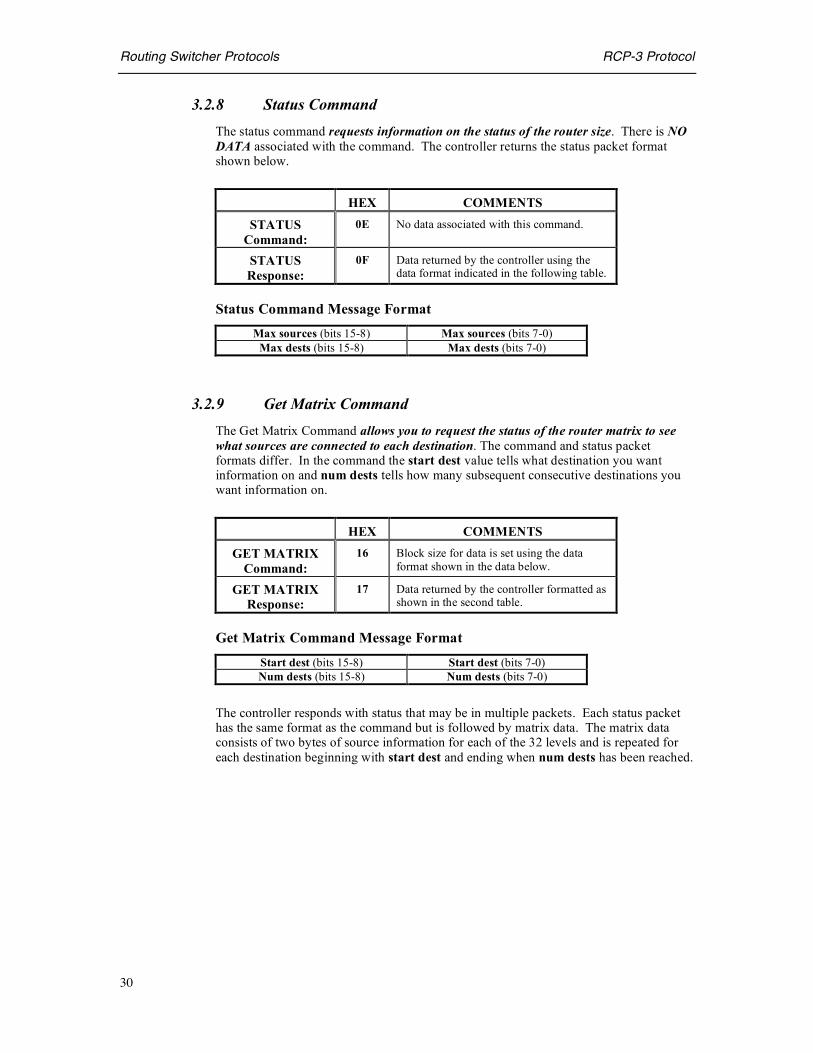
3.2.8 Status Command The status command requests information on the status of the router size. There is NO DATA associated with the command. The controller returns the status packet format shown below.
HEX COMMENTS
STATUS Command:
0E No data associated with this command.
STATUS Response:
0F Data returned by the controller using the data format indicated in the following table.
Status Command Message Format Max sources (bits 15-8) Max sources (bits 7-0)
Max dests (bits 15-8) Max dests (bits 7-0)
3.2.9 Get Matrix Command The Get Matrix Command allows you to request the status of the router matrix to see what sources are connected to each destination. The command and status packet formats differ. In the command the start dest value tells what destination you want information on and num dests tells how many subsequent consecutive destinations you want information on.
HEX COMMENTS
GET MATRIX Command:
16 Block size for data is set using the data format shown in the data below.
GET MATRIX Response:
17 Data returned by the controller formatted as shown in the second table.
Get Matrix Command Message Format
Start dest (bits 15-8) Start dest (bits 7-0) Num dests (bits 15-8) Num dests (bits 7-0)
The controller responds with status that may be in multiple packets. Each status packet has the same format as the command but is followed by matrix data. The matrix data consists of two bytes of source information for each of the 32 levels and is repeated for each destination beginning with start dest and ending when num dests has been reached.

Routing Switcher Protocols RCP-3 Protocol
31
Get Matrix Response Message Format
Start dest (bits 15-8) Start dest (bits 7-0) Num dests (bits 15-8) Num dests (bits 7-0) Level 1 src (bits 15-8) Level 1 src (bits 7-0) Level 2 src (bits 15-8) Level 2 src (bits 7-0) Level 3 src (bits 15-8) (and so on thru level 31) Level 32 src (bits 15-8) Level 32 src (bits 7-0) Level 1 src (bits 15-8) Level 1 src (bits 7-0) Level 2 src (bits 15-8) Level 2 src (bits 7-0) Level 2 src (bits 15-8) Level 2 src (bits 7-0) Level 4 src (bits 15-8) (and so on...)
3.2.10 Get Matrix Attributes Command The Get Matrix Attributes Command allows you to request the current attributes of the Router matrix for each destination. The command and response packet formats differ.
HEX COMMENTS
GET MATRIX ATTRIBUTES
Command:
1A No data associated with this command.
GET MATRIX ATTRIBUTES
Response:
1B Data returned by the controller formatted as shown in the following table.
Status can be returned in multiple packets. Each response packet identifies a block of destinations and is followed by the associated matrix attribute data. The matrix data consists of one byte of attribute information for each of the 32 levels and is repeated for each destination beginning with start dest and ending when num dests has been reached.
Get Matrix Attributes Response Data Format Start dest (bits 15-8) Start dest (bits 7-0) Num dests (bits 15-8) Num dests (bits 7-0)
Level 1 attribute Level 2 attribute Level 3 attribute Level 4 attribute Level 5 attribute Level 6 attribute
(and so on thru level 31) Level 32 attribute Level 1 attribute Level 2 attribute Level 3 attribute Level 4 attribute Level 5 attribute Level 6 attribute Level 7 attribute (and so on...)

Routing Switcher Protocols RCP-3 Protocol
32
3.2.11 Get Monitor Matrix Command The Get Monitor Matrix Command allows you to request the status of the router monitor matrix to see what destinations are connected for each level. There is NO DATA associated with the command.
HEX COMMENTS
GET MONITOR MATRIX
Command:
1E No data associated with this command.
GET MONTIOR MATRIX Response:
1F 2 bytes of data returned by the controller for each of the 32 levels with data formatted as in the following table:
Get Monitor Matrix Response Data Format Level 1 dest (bits 15-8) Level 1 dest (bits 7-0) Level 2 dest (bits 15-8) Level 2 dest (bits 7-0) Level 3 dest (bits 15-8) (and so on thru level 31)
Level 32 dest (bits 15-8) Level 32 dest (bits 7-0)
3.2.12 Set Lock Command The Set Lock command allows a U-Net destination to be protected from subsequent TAKEs in a specified manner. This operation is identical to the 0B/1B lock operation of CSP and other Partyline panels. In the command the lock type value specifies the 0B/1B lock type for each level. A bit set is a 1B lock. A bit cleared is a 0B lock. The level contains a bit set for each level that is to be locked. The panel value tells which U-Net node number to use as the panel that set the lock. The system will behave just as if a lock were set at the panel specified. There is NO DATA associated with the status. It is simply an acknowledgement that the command was received correctly.
HEX COMMENTS
SET LOCK Command:
2E Data formatted as in the following table.
SET LOCK Response:
2F Acknowledge only, no data associated with this response.
Set Lock Command Data Format Lock type (bits 31-24) Lock type (bits 23-16) Lock type (bits 15-8) Lock type (bits 7-0)
Level (bits 31-24) Level (bits 23-16) Level (bits 15-8) Level (bits 7-0)
Destination (bits 15-8) Destination (bits 7-0) Panel (bits 15-8) Panel (bits 7-0)

Routing Switcher Protocols RCP-3 Protocol
33
3.2.13 Get Lock Command The Get Lock Command allows you to query the controller for all lock information. You can find out which destinations are protected by which panels. There is NO DATA associated with the command. Status can be returned in multiple packets.
HEX COMMENTS
GET LOCK Command:
30 No data associated with this command
GET LOCK Response:
31 Controller responds with data formatted as in the following table:
The lock data for each destination consists of a lock type, level and two bytes of panel information for each of the 32 levels. This data is repeated for each destination beginning with start dest and ending when num dests has been reached. Each byte of panel information simply tells what panel made the lock for that respective level. Note that the panel information is only important for 0B locks.
Get Lock Response Data Format
Start dest (bits 15-8) Start dest (bits 7-0) Num dests (bits 15-8) Num dests (bits 7-0) Lock type (bits 31-24) Lock type (bits 23-16) Lock type (bits 15-8) Lock type (bits 7-0)
Level (bits 31-24) Level (bits 23-16) Level (bits 15-8) Level (bits 7-0)
Level 1 panel (bits 15-8) Level 1 panel (bits 7-0) Level 2 panel (bits 15-8) Level 2 panel (bits 7-0) Level 3 panel (bits 15-8) (and so on thru level 31) Level 32 panel (bits 15-8) Level 32 panel (bits 7-0)
Lock type (bits 31-24) Lock type (bits 23-16) Lock type (bits 15-8) Lock type (bits 7-0)
Level (bits 31-24) Level (bits 23-16) Level (bits 15-8) Level (bits 7-0)
Level 1 panel (bits 15-8) Level 1 panel (bits 7-0) Level 2 panel (bits 15-8) (and so on...)

Routing Switcher Protocols RCP-3 Protocol
34
3.2.14 Clear Lock Command U-NET panels (such as the SCP series panels) have the ability to lock any specific output. The Clear Lock Command allows locks on a destination to be cleared. In the command, the lock type is not used and should be set to zero. The level contains a bit set for each level that is to be cleared. The panel value tells which U-Net node number to use as the panel clearing the lock. The system will behave just as if a lock were cleared at the panel specified. There is NO DATA associated with the status. It is simply an acknowledgement that the command was received correctly.
HEX COMMENTS
CLEAR LOCK Command:
32 Data formatted as table below:
CLEAR LOCK Response:
33 Controller response to acknowledge command but does not return data.
Clear Lock Command Data Format
Lock type (bits 31-24) Lock type (bits 23-16) Lock type (bits 15-8) Lock type (bits 7-0)
Level (bits 31-24) Level (bits 23-16) Level (bits 15-8) Level (bits 7-0)
Destination (bits 15-8) Destination (bits 7-0) Panel (bits 15-8) Panel (bits 7-0)
3.2.15 Physical Disconnect Command The Physical Disconnect Command disconnects a destination on multiple levels. The controller responds with a status packet that serves as an acknowledgement that the command was received correctly. The disconnect command will physically disconnect the specified destination in the router hardware. This feature works with the UTAH-200 controller only. See section 2.1.5 Disconnect Command for further disconnect information.
HEX COMMENTS
DISCONNECT Command:
96 Data format as in table below
DISCONNECT Response:
97 DISCONNECT data is echoed back by the controller using the same data format used by the DISCONNECT command
Disconnect Command Message Format
Destination (bits 15-8) Destination (bits 7-0) Level (bits 31-24) Level (bits 23-16) Level (bits 15-8) Level (bits 7-0)

Routing Switcher Protocols RCP-3 Protocol
35
3.2.16 Command Code Summary This table lists the Command Codes used in the RCP-3 Protocol. The first column indicates the status code in hexadecimal notation. The second column indicates the direction of the message is from the External Control Device (ECD) to the System Controller (SC). The third column indicates the direction of communications is from the SC to the ECD.
Table 7: RCP-3 COMMAND CODE SUMMARY Code ECD
to SC SC to ECD
Command Protocol / Comments
00 x Take Command
01 x Take response from controller
02 x Attribute Command
03 x Attribute Response from controller
04 x Monitor Take
05 x Monitor Take Response from controller
06 x Disconnect Command (SC-3)
07 x Disconnect Response from controller (SC-3)
08 x Salvo command
09 x Salvo Response from controller
0E x Status command
0F x Status Response from controller
16 x Get Matrix Command
17 x Get Matrix Response from controller
1A x Get Matrix Attributes Command
1B x Get Matrix Attributes Response from controller
1E x Get Monitor Matrix Command
1F x Get Monitor Matrix Response from controller
2E x Set Lock Command
2F x Set Lock Response from controller
30 x Get Lock Command
31 x Get Lock Response from controller
32 x Clear Lock Command
33 x Clear Lock Response from controller
96 x Physical Disconnect Command (UTAH-200)
97 x Physical Disconnect Response from controller (UTAH-200)
FD x Ping Response from Controller
FE x Ping Command

Routing Switcher Protocols RCP-3 Protocol
36
3.3 Extended Command Messages This section provides details of the individual extended commands for the system controller. These commands are not officially part of the published RCP-3 protocol. They are included here for informational purposes. The syntax and semantics of these commands may change in the future. The user would normally use the RMS program or other software directly from the company to perform these functions.
3.3.1 Create AVS Command This command is used with the SC-3 only. It enables the AVS router subsystem and sets the operating parameters. It may be necessary to send the Destroy AVS command prior to creating a new AVS subsystem with different parameters.
HEX COMMENTS
CREATE AVS Command:
08 Data format as in table below
CREATE AVS Response:
09 CREATE AVS data is echoed back by the controller using the same data format used by the CREATE AVS command.
To send this command, set the interface in the packet header to hex 0E. A sync source of 00 corresponds to 525 sync (NTSC), 01 is for 625 sync (PAL).
Create AVS Command and Status Message Format Max srcs (bits 15-8) Max srcs (bits 7-0)
Max dests (bits 31-24) Max dests (bits 23-16) Max tielines (bits 15-8) Max tielines (bits 7-0) Sync source (bits 15-8) Sync source (bits 7-0)
3.3.2 Get AVS Command This command is used with the SC-3 only. It enables the user to request the status of the AVS subsystem and operating parameters.
HEX COMMENTS
GET AVS Command:
0C No data is associated with this command.
GET AVS Response:
0D GET AVS response uses the same data format used by the CREATE AVS command as shown below.
To send this command, set the interface in the packet header to hex 0E. A sync source of 00 corresponds to 525 sync (NTSC), 01 is for 625 sync (PAL).
Routing Switcher Protocols RCP-3 Protocol
37
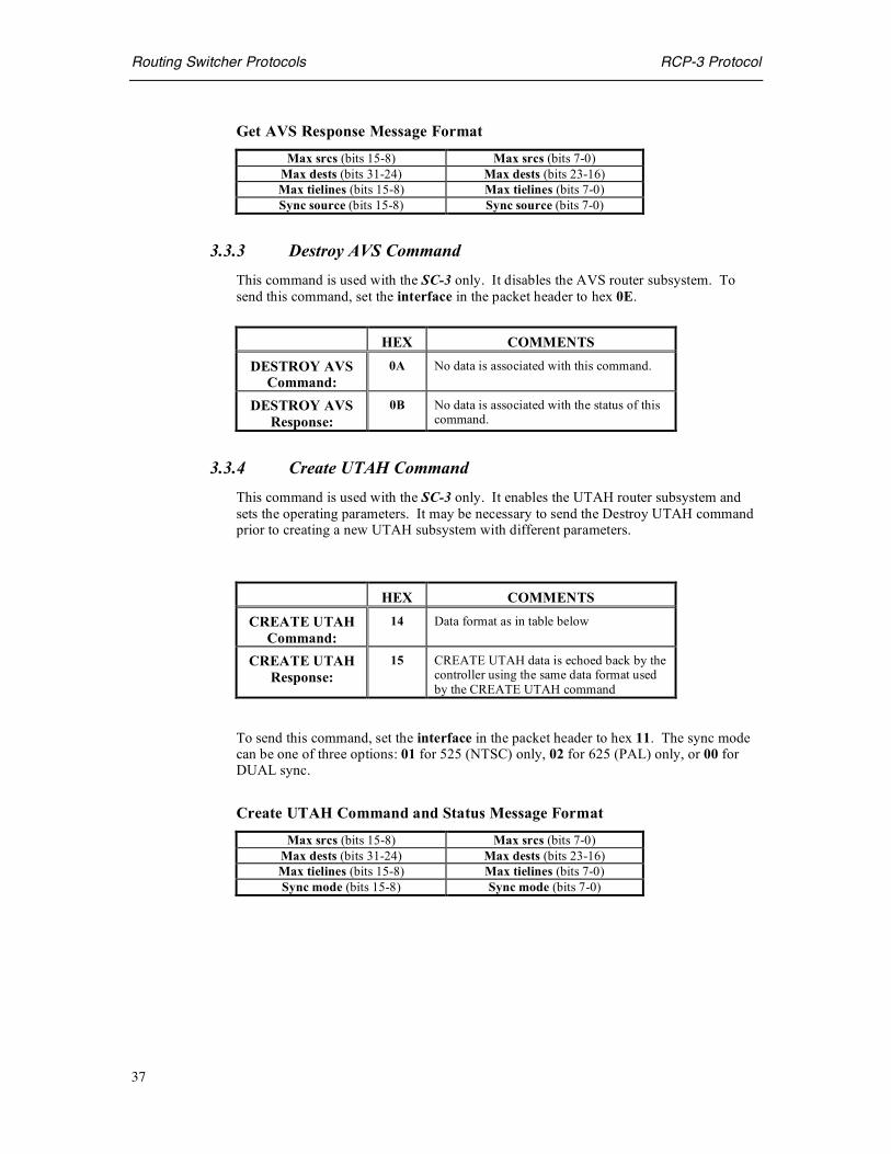
Get AVS Response Message Format
Max srcs (bits 15-8) Max srcs (bits 7-0) Max dests (bits 31-24) Max dests (bits 23-16) Max tielines (bits 15-8) Max tielines (bits 7-0) Sync source (bits 15-8) Sync source (bits 7-0)
3.3.3 Destroy AVS Command This command is used with the SC-3 only. It disables the AVS router subsystem. To send this command, set the interface in the packet header to hex 0E.
HEX COMMENTS
DESTROY AVS Command:
0A No data is associated with this command.
DESTROY AVS Response:
0B No data is associated with the status of this command.
3.3.4 Create UTAH Command This command is used with the SC-3 only. It enables the UTAH router subsystem and sets the operating parameters. It may be necessary to send the Destroy UTAH command prior to creating a new UTAH subsystem with different parameters.
HEX COMMENTS
CREATE UTAH Command:
14 Data format as in table below
CREATE UTAH Response:
15 CREATE UTAH data is echoed back by the controller using the same data format used by the CREATE UTAH command
To send this command, set the interface in the packet header to hex 11. The sync mode can be one of three options: 01 for 525 (NTSC) only, 02 for 625 (PAL) only, or 00 for DUAL sync.
Create UTAH Command and Status Message Format
Max srcs (bits 15-8) Max srcs (bits 7-0) Max dests (bits 31-24) Max dests (bits 23-16) Max tielines (bits 15-8) Max tielines (bits 7-0) Sync mode (bits 15-8) Sync mode (bits 7-0)

Routing Switcher Protocols RCP-3 Protocol
38
3.3.5 Get UTAH Command This command is used with the SC-3 or SC-4. It enables the user to request the status of the UTAH subsystem and operating parameters.
HEX COMMENTS
GET UTAH Command:
18 No data is associated with this command.
GET UTAH Response:
19 GET UTAH response uses the same data format used by the CREATE UTAH command as shown below.
To send this command, set the interface in the packet header to hex 11. The sync mode can be one of three options: 01 for 525 (NTSC) only, 02 for 625 (PAL) only, or 00 for DUAL sync.
Get UTAH Response Message Format Max srcs (bits 15-8) Max srcs (bits 7-0)
Max dests (bits 31-24) Max dests (bits 23-16) Max tielines (bits 15-8) Max tielines (bits 7-0) Sync source (bits 15-8) Sync source (bits 7-0)
3.3.6 Destroy UTAH Command This command is used with the SC-3 only. It disables the UTAH router subsystem. To send this command, set the interface in the packet header to hex 11.
HEX COMMENTS
DESTROY UTAH
Command:
16 No data is associated with this command.
DESTROY UTAH Response:
17 No data is associated with the status of this command.
3.3.7 Create SCP Command This command is used with the SC-3 only. It enables the SCP panel subsystem and sets the operating parameters. It may be necessary to send the Destroy SCP command prior to creating a new SCP panel subsystem with different parameters.

Routing Switcher Protocols RCP-3 Protocol
39
HEX COMMENTS
CREATE SCP Command:
0A Data format as in table below
CREATE SCP Response:
0B CREATE UTAH data is echoed back by the controller using the same data format used by the CREATE UTAH command
To send this command, set the interface in the packet header to hex 12.
Create SCP Command and Status Message Format
Max srcs (bits 15-8) Max srcs (bits 7-0) Max dests (bits 31-24) Max dests (bits 23-16)
3.3.8 Get SCP Command This command is used with the SC-3 or SC-4. It enables the user to request the status of the SCP panel subsystem and operating parameters.
HEX COMMENTS
GET SCP Command:
0E No data is associated with this command.
GET SCP Response:
0F GET UTAH response uses the same data format used by the CREATE UTAH command as shown below.
To send this command, set the interface in the packet header to hex 12.
Get UTAH Response Message Format Max srcs (bits 15-8) Max srcs (bits 7-0)
Max dests (bits 31-24) Max dests (bits 23-16)

Routing Switcher Protocols RCP-3 Protocol
40
3.3.9 Destroy SCP Command This command is used with the SC-3 only. It disables the SCP panel subsystem. To send this command, set the interface in the packet header to hex 12.
HEX COMMENTS
DESTROY SCP Command:
0C No data is associated with this command.
DESTROY SCP Response:
0D No data is associated with the status of this command.
3.3.10 Mapping Command
The mapping command allows configuration of the logical router system. Levels can be rearranged and different router types supported. A single router chassis can also be mapped into multiple logical levels.
This command is used with either the SC-3 or SC-4. The SC-3 will not function without initializing the mapping table using this command. Often this is done at the factory before the system is delivered to the end user. The SC-4 has a simple default mapping that will normally be sufficient for most cases but can be overridden using this command.
HEX Comments
MAPPING Command:
24 Data format as in table below.
MAPPING Response:
25 Response from controller to ECD.
Each entry in the mapping table defines a logical level. Start entry and num entry values tell which entries are to be updated by the command. The remaining values shown below define the logical level for an entry and are repeated as specified by num entries.
In general, the entire table should be updated with one series of commands, starting with a first entry of zero. Source and destination values start at zero but levels begin at one. The level type is 1 for AVS routers and 2 for the UTAH series of routers. The SC-4 does not support AVS routers at this time.

Routing Switcher Protocols RCP-3 Protocol
41
Mapping Command and Status Data Format.
Start entry (bits 15-8) Start entry (bits 7-0) Num entries (bits 15-8) Num entries (bits 7-0) Logical src (bits 15-8) Logical src (bits 7-0) Logical dst (bits 15-8) Logical dst (bits 7-0) Num srcs (bits 15-8) Num srcs (bits 7-0) Num dsts (bits 15-8) Num dsts (bits 7-0) Level type (bits 15-8) Level type (bits 7-0)
Physical src (bits 15-8) Physical src (bits 7-0) Physical dst (bits 15-8) Physical dst (bits 7-0)
padding padding Logical level (bits 15-8) Logical level (bits 7-0) Physical level (bits 15-8) Physical level (bits 7-0)
padding padding padding padding padding padding padding padding
3.3.11 Get Mapping Command The get mapping command requests the current mapping configuration.
HEX Comments
GET MAPPING Command:
26 No data associated with this command.
GET MAPPING Response:
27 Data formatted as defined in the following table.
See section 3.3.10 Mapping Command for more information about this data format.
Get Mapping Status Data Format.
Start entry (bits 15-8) Start entry (bits 7-0) Num entries (bits 15-8) Num entries (bits 7-0) Logical src (bits 15-8) Logical src (bits 7-0) Logical dst (bits 15-8) Logical dst (bits 7-0) Num srcs (bits 15-8) Num srcs (bits 7-0) Num dsts (bits 15-8) Num dsts (bits 7-0) Level type (bits 15-8) Level type (bits 7-0)
Physical src (bits 15-8) Physical src (bits 7-0) Physical dst (bits 15-8) Physical dst (bits 7-0)
padding padding Logical level (bits 15-8) Logical level (bits 7-0) Physical level (bits 15-8) Physical level (bits 7-0)
padding padding padding padding padding padding padding padding

Routing Switcher Protocols RCP-3 Protocol
42
3.4 SCP Panel Command Messages This section provides details of the individual SCP panel programming commands. These commands are not officially part of the published RCP-3 protocol. They are included here for informational purposes. The syntax and semantics of these commands may change in the future. The user would normally use the RMS program or other software directly from the company to perform these functions.
The SCP programming commands are different from other RCP-3 commands because the system controller simply acts as a gateway to the U-Net panel network. Because of this, panel commands need two headers, one for the controller and one for the panel. The header for the controller has the same format as the headers for other RCP-3 commands and is the same for all SCP panel commands. This header should precede all panel command messages and is documented in the following table.
Interface (12 hex) Command Type (53 hex) Data Checksum padding (00 hex)
Data Length (bits 15-8) Data Length (bits 7-0)
The data checksum is calculated as documented in section 3.0.6 and is calculated on the panel header and panel data.
The data length should include the size of the panel header and the panel data.
The panel header should be sent immediately after the controller header. The panel header is different in format from the controller header. It is twelve bytes in length and is formatted as follows:
Node ID Command Type (see subsections)
padding (00 hex) Send Interface padding (0 hex) Dest Interface (12 hex)
Data Length (bits 15-8) Data Length (bits 7-0) padding (0 hex) padding (0 hex) padding (0 hex) padding (0 hex)
The node ID identifies the panel to be programmed on the U-Net network.
The command type value identifies the command being sent. The command type values for each SCP panel command are different and are documented in the following subsections.
The send interface should be set to 02 for serial connections and 03 for socket Ethernet connections.
The dest interface should always be set to 12 hex.
The data length is the size of the header (12) plus the size of the data that follows the command.
The data for each command will immediately follow the panel header. Each command has a different data format. These formats are documented in the following subsections.
After a series of panel programming commands are sent the end reprogramming session command must be sent to get the panel out of reprogramming mode. This command is documented in section 3.4.15.

Routing Switcher Protocols RCP-3 Protocol
43
3.4.1 Set Panel ID Command
An arbitrary panel ID string can be stored on each SCP panel for identification purposes. This ID does not affect panel operation.
HEX Comments
SET PANEL ID Command:
06 Data format: ASCII panel ID string (32 bytes).
SET PANEL ID Response:
07 Not returned in most cases.
3.4.2 Get Panel ID Command
The panel ID string can be requested.
HEX Comments
SET PANEL ID Command:
08 Data format: ASCII panel ID string (32 bytes).
SET PANEL ID Response:
09 Not returned in most cases.
3.4.3 Set Source Group Name Command
The source group names can be set and associated with keypad buttons on certain panels such as the SCP-XY/16, SCP-2 and SCP-SX/MX models.
HEX Comments
SET SRC GRP Command:
18 Data format is documented below.
SET SRC GRP Response:
19 Not returned in most cases.

Routing Switcher Protocols RCP-3 Protocol
44
Set Source Group Name Data Format.
Start entry (bits 15-8) Start entry (bits 7-0) Num entries (bits 15-8) Num entries (bits 7-0)
Name (char 1) Name (char 2) Name (char 3) Name (char 4) Name (char 5) Name (char 6) Name (char 7) Name (char 8)
padding (00 hex) Key Num grp entries (bits 15-8) Num grp entries (bits 7-0)
Start entry identifies the beginning entry of the command. Num entries tells how many entries are in the command. Each entry contains the information for one device group. The name, key and num group entries values are repeated as many times as specified in num entries.
The key values range from 00 to 13 hex and correspond to the different keypad keys. The num group entries value tells how many source name entries are in the group. Source name entries are programmed with the set source name command.
3.4.4 Get Source Group Name Command
The source group names can requested from certain panels such as the SCP-XY/16, SCP-2 and SCP-SX/MX models.
HEX Comments
GET SRC GRP Command:
1C No data is associated with this command.
GET SRC GRP Response:
1D Data format documented below.
Get Source Group Name Response Data Format.
Start entry (bits 15-8) Start entry (bits 7-0) Num entries (bits 15-8) Num entries (bits 7-0)
Name (char 1) Name (char 2) Name (char 3) Name (char 4) Name (char 5) Name (char 6) Name (char 7) Name (char 8)
padding (00 hex) Key Num grp entries (bits 15-8) Num grp entries (bits 7-0)
Start entry identifies the beginning entry of the command. Num entries tells how many entries are in the command. Each entry contains the information for one device group. The name, key and num group entries values are repeated as many times as specified in num entries.

Routing Switcher Protocols RCP-3 Protocol
45
The key values range from 00 to 13 hex and correspond to the different keypad keys. The num group entries value tells how many source name entries are in the group. Source name entries are programmed with the set source name command.
3.4.5 Clear Source Group Name Command
This command clears the source group entries of a panel. This is useful to prepare the panel to receive new entries.
HEX Comments
CLR SRC GRP Command:
20 No data is associated with this command.
CLR SRC GRP Response:
21 Not returned in most cases.
3.4.6 Set Destination Group Name Command
The destination group names can be set and associated with keypad buttons on certain panels such as the SCP-XY/16, SCP-2 and SCP-SX/MX models.
HEX Comments
SET DST GRP Command:
1A Data format is documented below.
SET DST GRP Response:
1B Not returned in most cases.
Set Destination Group Name Data Format.
Start entry (bits 15-8) Start entry (bits 7-0) Num entries (bits 15-8) Num entries (bits 7-0)
Name (char 1) Name (char 2) Name (char 3) Name (char 4) Name (char 5) Name (char 6) Name (char 7) Name (char 8)
padding (00 hex) Key Num grp entries (bits 15-8) Num grp entries (bits 7-0)
Start entry identifies the beginning entry of the command. Num entries tells how many entries are in the command. Each entry contains the information for one device group. The name, key and num group entries values are repeated as many times as specified in num entries.
The key values range from 00 to 13 hex and correspond to the different keypad keys. The num group entries value tells how many destination name entries are in the group. Destination name entries are programmed with the set destination name command.
3.4.7 Get Destination Group Name Command

Routing Switcher Protocols RCP-3 Protocol
46
The destination group names can requested from certain panels such as the SCP-XY/16, SCP-2 and SCP-SX/MX models.
HEX Comments
GET DST GRP Command:
1E No data is associated with this command.
GET DST GRP Response:
1F Data format is documented below.
Get Destination Group Name Response Data Format.
Start entry (bits 15-8) Start entry (bits 7-0) Num entries (bits 15-8) Num entries (bits 7-0)
Name (char 1) Name (char 2) Name (char 3) Name (char 4) Name (char 5) Name (char 6) Name (char 7) Name (char 8)
padding (00 hex) Key Num grp entries (bits 15-8) Num grp entries (bits 7-0)
Start entry identifies the beginning entry of the command. Num entries tells how many entries are in the command. Each entry contains the information for one device group. The name, key and num group entries values are repeated as many times as specified in num entries.
The key values range from 00 to 13 hex and correspond to the different keypad keys. The num group entries value tells how many destination name entries are in the group. Destination name entries are programmed with the set destination name command.
3.4.8 Clear Destination Group Name Command
This command clears the destination group entries of a panel. This is useful to prepare the panel to receive new entries.
HEX Comments
CLR DST GRP Command:
22 No data is associated with this command.
CLR DST GRP Response:
23 Not returned in most cases.

Routing Switcher Protocols RCP-3 Protocol
47
3.4.9 Set Source Name Command
The source names can be set with this command. Some panels have direct source buttons such as the SCP-XY/16, SCP-2 and SCP-32 models. These can also be assigned with this command.
HEX Comments
SET SOURCE Command:
0C Data format is documented below.
SET SOURCE Response:
0D Not returned in most cases.
Set Source Name Data Format.
Start entry (bits 15-8) Start entry (bits 7-0) Num entries (bits 15-8) Num entries (bits 7-0)
Source name (char 1) Source name (char 2) Source name (char 3) Source name (char 4) Source name (char 5) Source name (char 6) Source name (char 7) Source name (char 8) Extension (bits 15-8) Extension (bits 7-0)
Key (bits 15-8) Key (bits 7-0) Level 1 numeric (bits 15-8) Level 1 numeric (bits 7-0) Level 2 numeric (bits 15-8) Level 2 numeric (bits 7-0) Level 3 numeric (bits 15-8) and so on…
… Level 15 numeric (bits 7-0) Level 16 numeric (bits 15-8) Level 16 numeric (bits 7-0)
Start entry identifies the beginning entry of the command. Num entries tells how many entries are in the command. Each entry contains the information for one source device. The name, extension, key and numeric values are repeated as many times as specified in num entries. Num entries should not exceed 5 for this command type, so multiple commands are generally required to specify the whole source table.
The source name can be up to eight characters long but will typically have five characters corresponding to the group name at the beginning and then three characters for the extension number. The extension value is simply a numeric representation of the ASCII extension in the source name. The key values range from 1A to 39 hex and correspond to the different direct source keys. However, some panels do not have this many keys dedicated to direct source operation. Sources without a direct source assignment should set this value to a –1 (FFFF hex). The numeric value for each of 16 possible levels correspond to the input on the router level. Unused levels should be set to –1 (FFFF hex).

Routing Switcher Protocols RCP-3 Protocol
48
3.4.10 Get Source Name Command
The source names can be retrieved with this command.
HEX Comments
GET SOURCE Command:
10 No data is associated with this command.
GET SOURCE Response:
11 Data format is documented below.
Get Source Name Response Data Format.
Start entry (bits 15-8) Start entry (bits 7-0) Num entries (bits 15-8) Num entries (bits 7-0)
Source name (char 1) Source name (char 2) Source name (char 3) Source name (char 4) Source name (char 5) Source name (char 6) Source name (char 7) Source name (char 8) Extension (bits 15-8) Extension (bits 7-0)
Key (bits 15-8) Key (bits 7-0) Level 1 numeric (bits 15-8) Level 1 numeric (bits 7-0) Level 2 numeric (bits 15-8) Level 2 numeric (bits 7-0) Level 3 numeric (bits 15-8) and so on…
… Level 15 numeric (bits 7-0) Level 16 numeric (bits 15-8) Level 16 numeric (bits 7-0)
Start entry identifies the beginning entry of the command. Num entries tells how many entries are in the command. Each entry contains the information for one source device. The name, extension, key and numeric values are repeated as many times as specified in num entries. Num entries should not exceed 5 for this command type, so multiple commands are generally required to specify the whole source table.
The source name can be up to eight characters long but will typically have five characters corresponding to the group name at the beginning and then three characters for the extension number. The extension value is simply a numeric representation of the ASCII extension in the source name. The key values range from 1A to 39 hex and correspond to the different direct source keys. However, some panels do not have this many keys dedicated to direct source operation. Sources without a direct source assignment should set this value to a –1 (FFFF hex). The numeric value for each of 16 possible levels correspond to the input on the router level. Unused levels should be set to –1 (FFFF hex).

Routing Switcher Protocols RCP-3 Protocol
49
3.4.11 Clear Source Name Command
This command clears the source entries of a panel. This is useful to prepare the panel to receive new entries.
HEX Comments
CLEAR SOURCE Command:
14 No data is associated with this command.
CLEAR SOURCE Response:
15 Not returned in most cases.
3.4.12 Set Destination Name Command
The destination names can be set with this command. Some panels have direct destination buttons such as the SCP-XY/16, SCP-2 and SCP-32 models. These can also be assigned with this command.
HEX Comments
SET DEST Command:
0E Data format is documented below.
SET DEST Response:
0F Not returned in most cases.
Set Destination Name Data Format.
Start entry (bits 15-8) Start entry (bits 7-0) Num entries (bits 15-8) Num entries (bits 7-0)
Dest name (char 1) Dest name (char 2) Dest name (char 3) Dest name (char 4) Dest name (char 5) Dest name (char 6) Dest name (char 7) Dest name (char 8)
Extension (bits 15-8) Extension (bits 7-0) Key (bits 15-8) Key (bits 7-0)
Level 1 numeric (bits 15-8) Level 1 numeric (bits 7-0) Level 2 numeric (bits 15-8) Level 2 numeric (bits 7-0) Level 3 numeric (bits 15-8) and so on…
… Level 15 numeric (bits 7-0) Level 16 numeric (bits 15-8) Level 16 numeric (bits 7-0)
Start entry identifies the beginning entry of the command. Num entries tells how many entries are in the command. Each entry contains the information for one source device. The dest name, extension, key and numeric values are repeated as many times as specified in num entries. Num entries should not exceed 5 for this command type, so multiple commands are generally required to specify the whole source table.
The dest name can be up to eight characters long but will typically have five characters corresponding to the group name at the beginning and then three characters for the
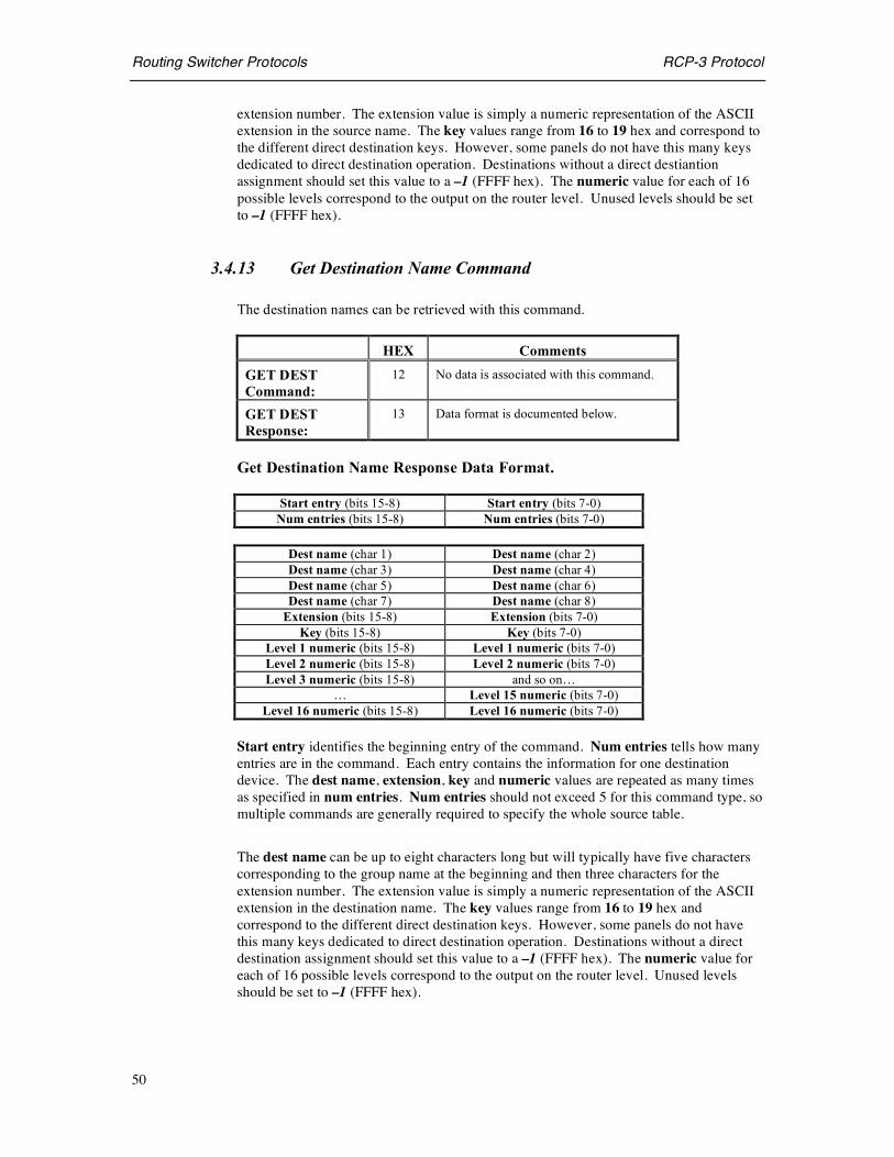
Routing Switcher Protocols RCP-3 Protocol
50
extension number. The extension value is simply a numeric representation of the ASCII extension in the source name. The key values range from 16 to 19 hex and correspond to the different direct destination keys. However, some panels do not have this many keys dedicated to direct destination operation. Destinations without a direct destiantion assignment should set this value to a –1 (FFFF hex). The numeric value for each of 16 possible levels correspond to the output on the router level. Unused levels should be set to –1 (FFFF hex).
3.4.13 Get Destination Name Command
The destination names can be retrieved with this command.
HEX Comments
GET DEST Command:
12 No data is associated with this command.
GET DEST Response:
13 Data format is documented below.
Get Destination Name Response Data Format.
Start entry (bits 15-8) Start entry (bits 7-0) Num entries (bits 15-8) Num entries (bits 7-0)
Dest name (char 1) Dest name (char 2) Dest name (char 3) Dest name (char 4) Dest name (char 5) Dest name (char 6) Dest name (char 7) Dest name (char 8)
Extension (bits 15-8) Extension (bits 7-0) Key (bits 15-8) Key (bits 7-0)
Level 1 numeric (bits 15-8) Level 1 numeric (bits 7-0) Level 2 numeric (bits 15-8) Level 2 numeric (bits 7-0) Level 3 numeric (bits 15-8) and so on…
… Level 15 numeric (bits 7-0) Level 16 numeric (bits 15-8) Level 16 numeric (bits 7-0)
Start entry identifies the beginning entry of the command. Num entries tells how many entries are in the command. Each entry contains the information for one destination device. The dest name, extension, key and numeric values are repeated as many times as specified in num entries. Num entries should not exceed 5 for this command type, so multiple commands are generally required to specify the whole source table.
The dest name can be up to eight characters long but will typically have five characters corresponding to the group name at the beginning and then three characters for the extension number. The extension value is simply a numeric representation of the ASCII extension in the destination name. The key values range from 16 to 19 hex and correspond to the different direct destination keys. However, some panels do not have this many keys dedicated to direct destination operation. Destinations without a direct destination assignment should set this value to a –1 (FFFF hex). The numeric value for each of 16 possible levels correspond to the output on the router level. Unused levels should be set to –1 (FFFF hex).

Routing Switcher Protocols RCP-3 Protocol
51
3.4.14 Clear Destination Name Command
This command clears the destination entries of a panel. This is useful to prepare the panel to receive new entries.
HEX Comments
CLEAR DEST Command:
16 No data is associated with this command.
CLEAR DEST Response:
17 Not returned in most cases.
3.4.15 End Reprogramming Session Command
This command terminates the programming process and takes the panel out of reprogramming mode.
HEX Comments
END SESSION Command:
2A No data is associated with this command.
END SESSION Response:
2B Not returned in most cases.
3.5 Status Messages This section details status messages from the controller. The controller sends these messages automatically, without instigation by the ECD.
3.5.1 System Take Status The System Take Status is a special status generated by the controller in response to any system wide TAKE inclusive of TAKEs made by control panels or other control devices.
HEX COMMENTS
SYSTEM TAKE Status:
5F TAKE activity in the controller automatically triggers this response to the ECD. This is a status message and not instigated by a specific command. Data is formatted as in the table below :

Routing Switcher Protocols RCP-3 Protocol
52
System Take Status Data Format
Source (bits 15-8) Source (bits 7-0) Destination (bits 15-8) Destination (bits 7-0)
Level (bits 31-24) Level (bits 23-16) Level (bits 15-8) Level (bits 7-0)
3.5.2 System Attribute Status The System Attribute Status is a special status generated by the controller any time that ATTRIBUTES are changed on any part of the matrix configured in the System Controller, inclusive of changes made by control panels or other control devices.
HEX COMMENTS
SYSTEM TAKE Status:
60 ATTRIBUTE change activity in the controller automatically triggers this response to the ECD. This is a status message and not instigated by a specific command. Data is formatted as in the table below.
System Attribute Status Data Format
Attribute (bits 15-8) Attribute (bits 7-0) Destination (bits 15-8) Destination (bits 7-0)
Level (bits 31-24) Level (bits 23-16) Level (bits 15-8) Level (bits 7-0)
3.5.3 System Monitor Matrix Take Status The System Monitor Take Status is a special status generated by the controller any time Monitor Matrix TAKE’s are made on any matrix configured in the System controller.
HEX COMMENTS
SYSTEM MONITOR
TAKE Status:
61 MONITOR TAKE activity in the controller automatically triggers this response to the ECD. This is a status message and not instigated by a specific command. Data is formatted as in the table below :
System Monitor Take Status Data Format Destination (bits 15-8) Destination (bits 7-0)
Level (bits 31-24) Level (bits 23-16) Level (bits 15-8) Level (bits 7-0)

Routing Switcher Protocols RCP-3 Protocol
53
3.5.4 System Lock Status The System Lock Status is a special status generated any time lock changes are made that correspond to destinations on any matrix configured in the System Controller. A Status Type of 0 means this is a Lock Set Status. Any other value indicates a Lock Clear Status. A Lock Type value of 0 means this is a 1B Lock Status. Any other value indicates a 0B Lock Status.
HEX COMMENTS
SYSTEM MONITOR
TAKE Status:
62 SYSTEM LOCK change activity in the controller automatically triggers this response to the ECD. This is a status message and not instigated by a specific command. Data is formatted as in the table below.
System Lock Status Data Format 00 hex (padding ) 00 hex (padding ) Panel (bits 15-8) Panel (bits 7-0)
Destination (bits 15-8) Destination (bits 7-0) 00 hex (padding ) Status type Level (bits 31-24) Level (bits 23-16) Level (bits 15-8) Level (bits 7-0) 00 hex (padding ) 00 hex (padding ) 00 hex (padding ) Lock type 00 hex (padding ) 00 hex (padding )

Routing Switcher Protocols RCP-3 Protocol
54
3.5.5 Status Message Code Summary This table lists the Status Message Codes used in the RCP-3 Protocol. The first column indicates the status code in hexadecimal notation. The second column indicates the direction of the message is from the External Control Device (ECD) to the System Controller (SC). The third column indicates the direction of communications is from the SC to the ECD.
RCP-3 STATUS CODE TABLE
Code ECD to SC
SC to ECD
Command Protocol / Comments
5F x System Take Status from controller
60 x System Attribute Status from controller
61 x System Monitor Take Status from controller
62 x System Lock Status from controller
3.6 Error Status Formats Error Status may be received from the System controller at any time for a number of different reasons. Some indicate serious problems and some are simply informational. The packet format for error status is similar to that of other status packets. The Header Interface and Status Type values are listed under the headings below. The data format for all Error Status Packets consists of eight bytes. The specific meaning of the data for each error status is undocumented and is intended to be used for engineering troubleshooting purposes only.
3.6.1 Panel Error Status The Interface Value in the packet header for panel error status is 07 hexadecimal. The Status Type for each error is listed below in hexadecimal format:
Error Status Type
Unable to create Table Semaphores. 00 Refresh Enable Table too large. 01 Refresh Table too large. 02 Follow Table too large. 03 Mapping Table too large. 04 Salvo Buffer Number out of range. 05 Requested and Existing Panel Parameters do not agree. 06 Unable to allocate battery backed up Panel Object Parameters. 07 Unable to allocate battery backed up Panel Data Tables. 08 Unable to allocate Refresh Enable Working Buffer. 09 Unable to allocate Follow Working Buffer. 0A Salvo contains too many entries. 0B Invalid Mapping Table Entry. 0C

Routing Switcher Protocols RCP-3 Protocol
55
3.6.2 Error Status The interface value in the packet header for U-Net error status is 0x0A hexadecimal. The status type for each error is listed below in hexadecimal format:
Error Status Type
Check Sum Error. 00 Unrecognized SC Command. 01 Unrecognized MX Command. 02 Unrecognized Command. 03 Unrecognized Group. 04 Invalid Mapping Protocol. 05 Unrecognized Command Received from Panel. 06 Unrecognized Salvo Command Type. 07 Requested and Existing U-Net Parameters do not agree. 08 Disconnect Protocol is Invalid. 09 Destination / Level already Locked (dynamic). 0A Panel issuing Lock is out of range. 0B Lock Destination is out of range. 0C Invalid Lock Source (static). 0D Invalid Lock Type (static). 0E Maximum Number of Static Locks exceeded. 0F Lock to be deleted cannot be found. 10 Bad Lock Mode. 11 Unable to Map Dynamic Lock from Router Space to U-Net Space. 12 Unable to Map Lock Broadcast from U-Net Space to Router Space. 13 Bad Talkback Destination. 14 Same Talkback. 15 Unable to Allocate Battery backed up U-Net Object Parameters. 16 Unable to Allocate Battery backed up U-Net Data Tables. 17 Unable to instantiate (create) U-Net Interface Object. 18 Unable to spawn U-Net Interface Read Task. 19 Unable to spawn U-Net Refresh Fetch Task. 1A Invalid U-Net Reprogramming Command. 1B Panel Base Class instantiation (creation) unsuccessful. 1C Attribute Table too large. 1D Unable to spawn Heartbeat Task. 1E Unable to create Transmit Buffer. 1F Unable to spawn Write Task. 20 Multi-Command buffer full. 21 Output out of range. 22 Source out of range. 23 Unable to create Semaphore. 24
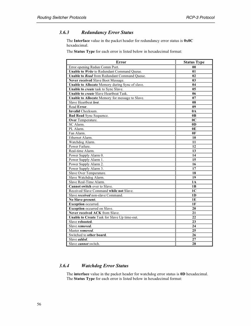
Routing Switcher Protocols RCP-3 Protocol
56
3.6.3 Redundancy Error Status The Interface value in the packet header for redundancy error status is 0x0C hexadecimal. The Status Type for each error is listed below in hexadecimal format:
Error Status Type
Error opening Redun Comm Port. 00 Unable to Write to Redundant Command Queue. 01 Unable to Read from Redundant Command Queue. 02 Never received Slave Boot Message. 03 Unable to Allocate Memory during Sync of slave. 04 Unable to create task to Sync Slave. 05 Unable to create Slave Heartbeat Task. 06 Unable to Allocate Memory for message to Slave. 07 Slave Heartbeat lost. 08 Read Error. 09 Invalid Checksum. 0A Bad Read Sync Sequence. 0B Over Temperature. 0C SC Alarm. 0D PL Alarm. 0E Fan Alarm. 0F Ethernet Alarm. 10 Watchdog Alarm. 11 Power Failure. 12 Real-time Alarm. 13 Power Supply Alarm 0. 14 Power Supply Alarm 1. 15 Power Supply Alarm 2. 16 Power Supply Alarm 3. 17 Slave Over Temperature. 18 Slave Watchdog Alarm. 19 Slave Real-Time Alarm. 1A Cannot switch over to Slave. 1B Received Slave Command while not Slave. 1C Slave received non-slave Command. 1D No Slave present. 1E Exception occurred. 1F Exception occurred on Slave. 20 Never received ACK from Slave. 21 Unable to Create Task for Slave Up time-out. 22 Slave rebooted. 23 Slave removed. 24 Master removed. 25 Switched to other board. 26 Slave added. 27 Slave cannot switch. 28
3.6.4 Watchdog Error Status The interface value in the packet header for watchdog error status is 0D hexadecimal. The Status Type for each error is listed below in hexadecimal format:

Routing Switcher Protocols RCP-3 Protocol
57
Error Status Type Watchdog time-out error 00 Unrecognized command 01
3.6.5 General SC-3 Error Status The interface value in the packet header for general SC-3 error status is 0D hexadecimal. The Status Type for each error is listed below in hexadecimal format:
Error Status Type
Invalid Socket ID. 00 Invalid Interface, cannot set / get message verbosity. 01 Unrecognized Broadcast Verbosity Configuration Command. 02 Unrecognized Panel Broadcast Command. 03 Unavailable socket slot. 04 SC Object already instantiated (created). 05 Requested SC Creation Parameters out of range. 06 SC Object not yet instantiated (created). 07 MX Object already instantiated (created). 08 Requested MX Creation Parameters out of range. 09 MX Object not yet instantiated (created). 0A PL Object already instantiated (created). 0B Requested PL Creation Parameters out of range. 0C PL Object not yet instantiated (created). 0D U-Net Object already instantiated (created). 0E Requested U-Net Creation Parameters out of range. 0F U-Net Object not yet instantiated (created). 10 Unrecognized Protocol Interface. 11 Unable to open Remote Serial Communication Port. 12 Unable to spawn Remote Serial Communication I/O Task. 13 Unable to create Remote Serial Communication Semaphore. 14 Error while reading from Remote Serial Communication Port. 15 Unable to allocate Remote Serial Communication working buffer. 16 Unable to close Remote Serial Communication Port. 17 Remote Serial Communication Packet check sum error. 18 Unable to open Remote Communication Socket. 19 Unable to bind Remote Communication Socket. 1A Unable to listen to Remote Communication Socket. 1B Unable to start Remote Communication Socket Server Task. 1C Unable to create Remote Communication Socket Semaphore. 1D Unable to close Remote Communication Socket. 1E Unable to write to Remote Communication Socket. 1F Unable to accept Remote Communication Socket Connection. 20 Maximum Remote Communication Socket Connections used. 21 Unable to start Remote Communication Socket Read Task. 22 Unable to allocate Remote Communication Socket Data Buffer. 23 Remote Communication Socket Data check sum error. 24

Routing Switcher Protocols Appendix A
58
APPENDIX
ASCII Code Table
Table A-1: ASCII Codes (Hexadecimal) HEX SYMB KEY HEX SYMB HEX SYMB HEX SYMB
00 NUL CTRL @ 20 Space 40 @ 60 `
01 SOH CTRL A 21 ! 41 A 61 a 02 STX CTRL B 22 “ 42 B 62 b 03 ETX CTRL C 23 # 43 C 63 c
04 EOT CTRL D 24 $ 44 D 64 d 05 ENQ CTRL E 25 % 45 E 65 e 06 ACK CTRL F 26 & 46 F 66 f
07 BEL CTRL G 27 ‘ 47 G 67 g 08 BS CTRL H 28 ( 48 H 68 h 09 HT CTRL I 29 ) 49 I 69 i 0A LF CTRL J 2A * 4A J 6A j
0B VT CTRL K 2B + 4B K 6B k 0C FF CTRL L 2C , 4C L 6C l 0D CR CTRL M 2D - 4D M 6D m
0E SO CTRL N 2E . 4E N 6E n 0F SI CTRL O 2F / 4F O 6F o 10 DLE CTRL P 30 0 50 P 70 p 11 DC1 CTRL Q 31 1 51 Q 71 q
12 DC2 CTRL R 32 2 52 R 72 r 13 DC3 CTRL S 33 3 53 S 73 s 14 DC4 CTRL T 34 4 54 T 74 t
15 NAK CTRL U 35 5 55 U 75 u 16 SYN CTRL V 36 6 56 V 76 v 17 ETB CTRL W 37 7 57 W 77 w 18 CAN CTRL X 38 8 58 X 78 x
19 EM CTRL Y 39 9 59 Y 79 y 1A SUB CTRL Z 3A : 5A Z 7A z 1B ESC CTRL [ 3B ; 5B [ 7B { 1C FS CTRL \ 3C < 5C \ 7C |
1D GS CTRL ] 3D = 5D ] 7D } 1E RS CTRL ^ 3E > 5E ^ 7E ~ 1F US CTRL _ 3F ? 5F _ 7F DEL

Routing Switcher Protocols Appendix A
59
This page intentionally left blank


![[MS-RDSOD]: Remote Desktop Services Protocols Overview](https://static.fdocuments.us/doc/165x107/624a2d04baf35c2ffb6b7c21/ms-rdsod-remote-desktop-services-protocols-overview.jpg)