Remote Digital Flow Switch Series PFM5content.smcetech.com/pdf/PFM5_8622E.pdf2-Color Display Digital...
19
How to Order With one-touch fittings (C4, C6, C8, N7) Female thread (01, 02, N01, N02, F01, F02) Straight (Nil) Without flow adjustment valve (Nil) With flow adjustment valve (S) Bottom (L) Straight (Nil) Bottom (L) Piping Variations 2-Color Display Digital Flow Switch Series PFM5 Remote sensor unit PFM 5 10 C4 1 Type Remote sensor unit 5 Flow adjustment valve Nil S None Yes Calibration certificate None With calibration certificate Nil A ∗ The certificate is written in English and Japanese. Other languages are available as specials. Instruction manual With instruction manual (Leaflet: Japanese and English) None Nil N Output specification No. 1 2 Description Analog output (1 to 5 V) Analog output (4 to 20 mA) Applicable display unit PFM30 PFM31 Piping entry direction Nil L Straight Bottom Port size ∗ Different combinations of piping entry directions for IN and OUT side are available as made-to-order. (Refer to page 35.) 0.2 to 10 (5) l/min 0.5 to 25 (12.5) l/min 1 to 50 (25) l/min 2 to 100 (50) l/min 10 25 50 11 ∗ ( ): Fluid: CO2 Rated flow range (Flow rate range) Option 1 (Refer to page 14.) Option 2 (Refer to page 14.) Made to Order (Refer to page 14 and 35.) ® Remote sensor unit Symbol Description Flow rate range 10 25 50 11 01 02 N01 N02 F01 F02 C4 C6 C8 N7 Rc1/8 Rc1/4 NPT1/8 NPT1/4 G1/8 G1/4 ø4 (5/32") one-touch fitting ø6 one-touch fitting ø8 (5/16") one-touch fitting ø1/4 one-touch fitting 13
Transcript of Remote Digital Flow Switch Series PFM5content.smcetech.com/pdf/PFM5_8622E.pdf2-Color Display Digital...
How to Order
With one-touch fittings (C4, C6, C8, N7) Female thread (01, 02, N01, N02, F01, F02)
Straight (Nil)
Withoutflow
adjustmentvalve(Nil)
Withflow
adjustmentvalve
(S)
Bottom (L) Straight (Nil) Bottom (L)
Piping Variations
2-Color DisplayDigital Flow Switch
Series PFM5Remote
sensor unit
PFM5 10 C4 1Type
Remote sensor unit5
Flow adjustment valveNilS
NoneYes
Calibration certificateNone
With calibration certificateNilA
∗ The certificate is written in English and Japanese. Other languages are available as specials.
Instruction manualWith instruction manual (Leaflet: Japanese and English)
NoneNilN
Output specificationNo.12
DescriptionAnalog output (1 to 5 V)Analog output (4 to 20 mA)
Applicable display unitPFM30�PFM31�
Piping entry directionNilL
StraightBottom
Port size
∗ Different combinations of piping entry directions for IN and OUT side are available as made-to-order. (Refer to page 35.)
0.2 to 10 (5) l/min0.5 to 25 (12.5) l/min1 to 50 (25) l/min2 to 100 (50) l/min
10255011
∗ ( ): Fluid: CO2
Rated flow range (Flow rate range)
Option 1 (Refer to page 14.)
Option 2 (Refer to page 14.)
Made to Order(Refer to page 14 and 35.)
®
Remotesensor unit
Symbol DescriptionFlow rate range
10�
�
�
��
25�
�
�
���
50�
�
�
���
11
�
�
�
���
0102
N01N02F01F02C4C6C8N7
Rc1/8Rc1/4
NPT1/8NPT1/4
G1/8G1/4
ø4 (5/32") one-touch fittingø6 one-touch fitting
ø8 (5/16") one-touch fittingø1/4 one-touch fitting
13
DIN Rail Mounting Bracket (Order Separately)
ZS-33-JZS-33-M ZS-33-MS
ZS 33 RStations
1 station2 stations3 stations4 stations5 stations
12345
NilNone
VPanel mount adapter
(For with flow adjustment valve)
Option 1Nil
With lead wire with connector (2 m)
RBracket
(For without flow adjustment valve)
SBracket
(For with flow adjustment valve)
Piping direction: Cannot be mounted with bottom piping type.
TPanel mount adapter
(For without flow adjustment valve)
ZWithout lead wire with connector
Option 2
ZS-33-D
ZS-33-JS
Mounting bracket
Panel mountadapter B
Panel mountadapter A
Panel
Panel mountadapter A
Panel
Panel mountadapter B
Mounting bracket
Mountingscrew(accessory)
Mountingscrew(accessory)
Lead wire length 2 m Lead wire length 2 m
Each option is not assembled with the product, but shipped together.
Made to Order
X693X694
Change of piping entry directioncombination
Specification/DescriptionSymbol
For details, refer to page 35 and 36.
WWith lead wire with connector (2 m) +Rubber cover for connector (silicon rubber)
ZS-33-F
ZS-33-D
• DIN rail (supplied by customers)• Port size F02: G1/4 cannot be mounted on the DIN rail.
14
2-Color Display Digital Flow Switch Series PFM5
Note: Flow rate unit is based on standard conditions (20ºC, 1 atm, 65% RH).
Model PFM510 PFM525 PFM550 PFM511
Applicable fluid
Pressure characteristics
Power supply voltage
Current consumption
Repeatability
Operating pressure range
Rated pressure range
Proof pressure
Status LED’s
Environ-mentalresistance
Rated flow range Note)
(Flow rate range)Dry air, N2, Ar
CO2
Response time
Enclosure
Operating fluid temperature
Operating temperature range
Operating humidity range
Withstand voltage
Insulation resistance
Vibration resistance
Impact resistance
Voltage output
Current output
Dry air, N2, Ar, CO2
(Air quality grade is JIS B8392.1-1, 1.2 to 1.6.2 and ISO8573.1-1, 1.2 to 1.6.2.)
0.2 to 10 l/min
0.2 to 5 l/min
0.5 to 25 l/min
0.5 to 12.5 l/min
±1%F.S. or less (Fluid: Dry air)
±5%F.S. or less (based on 0.35 MPa)
–100 kPa to 750 kPa
–70 kPa to 750 kPa
1 MPa
50 msec or 1 s (with response time selection function: 1 s at no-voltage input)→ Refer to the internal circuits and wiring examples on page 16.
24 VDC ±10%
35 mA or less
IP40
0 to 50ºC (with no freezing and condensation)
Operating: 0 to 50ºC Stored: –10 to 60ºC (with no freezing and condensation)
Operating, Stored: 35 to 85%R.H. (with no condensation)
1000 VAC for 1 min. between external terminal and case
50 M or more (500 VDC Mega) between external terminal and case
490 m/s2 in X, Y, Z directions 3 times each
±2%F.S. (15 to 35ºC)±5%F.S. (0 to 50ºC)
Voltage output: 1 to 5 VOutput impedance: 1 k
Current output: 4 to 20 mAMax. load impedance: 600 , Min. load impedance: 50
Without orifice: 10 to 500 Hz with a 1.5 mm amplitude or 98 m/s2 acceleration, in each X, Y, Z direction for 2 hrs, whichever is smaller.With orifice: 10 to 150 Hz with a 1.5 mm amplitude or 19.6 m/s2 acceleration, in each X, Y, Z direction for 2 hrs, whichever is smaller.
Power ON indicator: Lights when power is turned on (Green).Flow rate indicator: Flashes when flow is applied (Green).
Accuracy
Temperature characteristics
Analog output
±3%F.S. or less
1 to 50 l/min
1 to 25 l/min
2 to 100 l/min
2 to 50 l/min
Specifications
15
Series PFM5
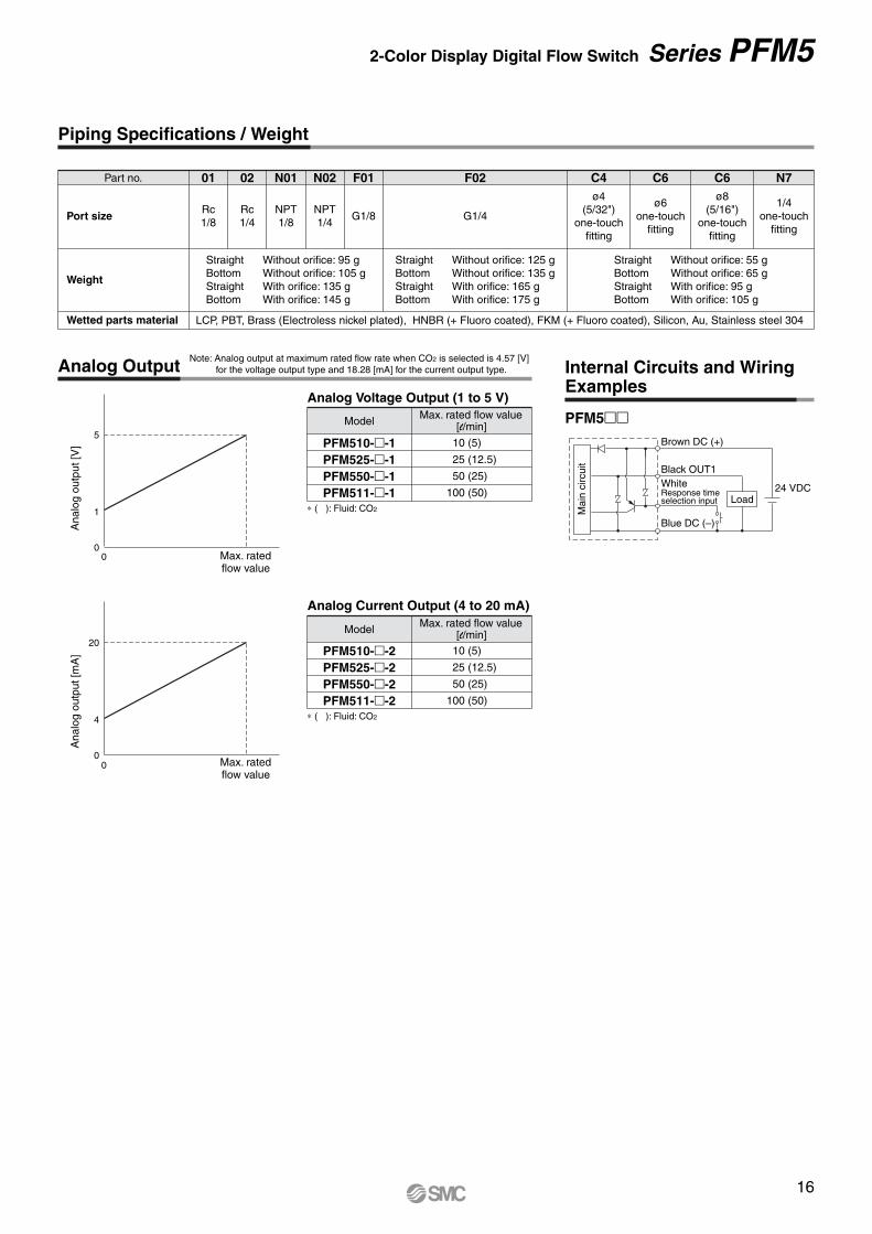
Analog Output Internal Circuits and Wiring Examples
Part no. 01
Port size
Weight
Wetted parts material
Straight Without orifice: 125 gBottom Without orifice: 135 gStraight With orifice: 165 gBottom With orifice: 175 g
Straight Without orifice: 55 gBottom Without orifice: 65 gStraight With orifice: 95 gBottom With orifice: 105 g
Straight Without orifice: 95 gBottom Without orifice: 105 gStraight With orifice: 135 gBottom With orifice: 145 g
LCP, PBT, Brass (Electroless nickel plated), HNBR (+ Fluoro coated), FKM (+ Fluoro coated), Silicon, Au, Stainless steel 304
Rc1/8
02
Rc1/4
N01
NPT1/8
N02
NPT1/4
F01
G1/8 G1/4
C4F02ø4
(5/32")one-touch
fitting
C6
ø6one-touch
fitting
C6ø8
(5/16")one-touch
fitting
N7
1/4one-touch
fitting
10 (5)
25 (12.5)
50 (25)
100 (50)
PFM510-�-1PFM525-�-1PFM550-�-1PFM511-�-1
Analog Voltage Output (1 to 5 V)
Model Max. rated flow value[l/min]
10 (5)
25 (12.5)
50 (25)
100 (50)
PFM510-�-2PFM525-�-2PFM550-�-2PFM511-�-2
Analog Current Output (4 to 20 mA)
Model Max. rated flow value[l/min]
Max. ratedflow value
0
4
20
Max. ratedflow value
00
0
1
5
PFM5��Brown DC (+)
Black OUT1WhiteResponse timeselection input
Blue DC (–)
24 VDCLoad
∗ ( ): Fluid: CO2
∗ ( ): Fluid: CO2
Note: Analog output at maximum rated flow rate when CO2 is selected is 4.57 [V] for the voltage output type and 18.28 [mA] for the current output type.
Piping Specifications / Weight
Ana
log
outp
ut [V
]A
nalo
g ou
tput
[mA
]
Mai
n ci
rcui
t
16
2-Color Display Digital Flow Switch Series PFM5
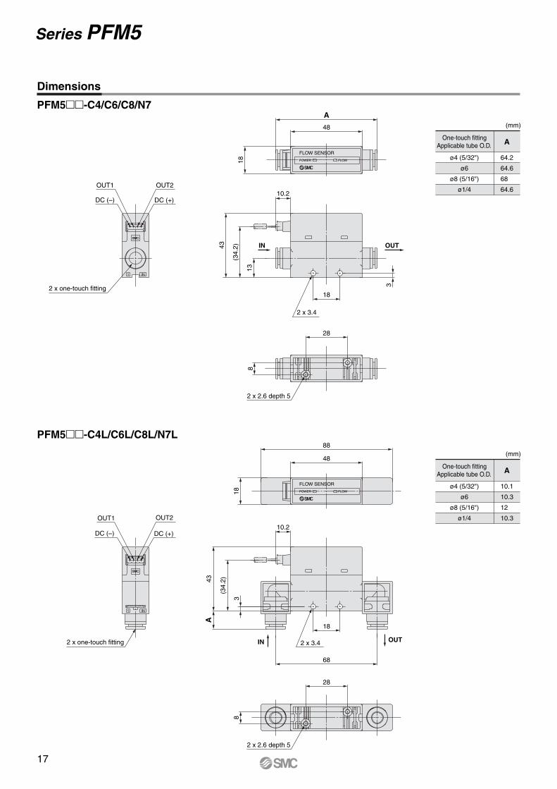
PFM5��-C4/C6/C8/N7
(mm)
One-touch fittingApplicable tube O.D.
ø4 (5/32")
ø6
ø8 (5/16")
ø1/4
A
64.2
64.6
68
64.6
PFM5��-C4L/C6L/C8L/N7L
(mm)
One-touch fittingApplicable tube O.D.
ø4 (5/32")
ø6
ø8 (5/16")
ø1/4
A
10.1
10.3
12
10.3
1 IN
OUT1
DC (–)
OUT2
DC (+)
2 x one-touch fitting
1 IN
2 x one-touch fitting
OUT1
DC (–)
OUT2
DC (+)
18
68
10.2
3
(34.
2)43A
2 x 3.4 OUTIN
18
10.2
43
3
13
(34.
2)
2 x 3.4
IN OUT18
48
A
FLOW SENSOR
POWER FLOW
18
48
88
FLOW SENSOR
POWER FLOW
28
8
2 x 2.6 depth 5
28
8
2 x 2.6 depth 5
Dimensions
17
Series PFM5
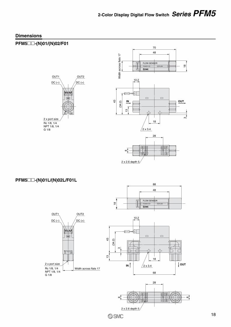
PFM5��-(N)01/(N)02/F01
PFM5��-(N)01L/(N)02L/F01L
1 IN
2 x port size
Rc 1/8, 1/4NPT 1/8, 1/4G 1/8
DC (+)DC (–)
OUT2OUT1
2 x 3.4
18
43
13
10.2
3
(34.
2) IN OUT
1 IN
Width across flats 17
DC (+)DC (–)
OUT2OUT1
2 x port size
Rc 1/8, 1/4NPT 1/8, 1/4G 1/8
68
3
(34.
2)
18
43
10.2
13
2 x 3.4IN OUT
48
70
Wid
th a
cros
s fla
ts 1
7
18
FLOW SENSOR
POWER FLOW
88
48
18
FLOW SENSOR
POWER FLOW
28
8
2 x 2.6 depth 5
28
8
2 x 2.6 depth 5
8
Dimensions
18
2-Color Display Digital Flow Switch Series PFM5
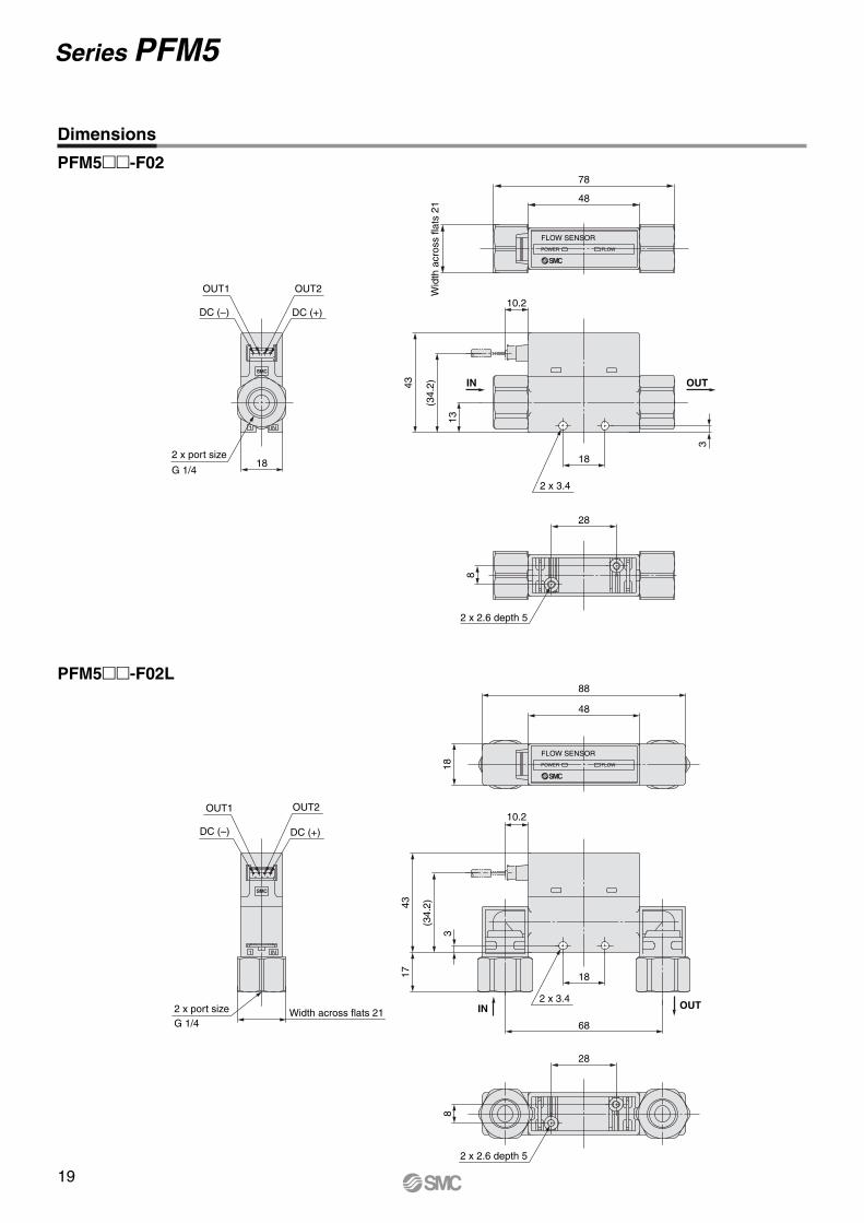
PFM5��-F02
PFM5��-F02L
1 IN
18
OUT1
DC (–)
OUT2
DC (+)
2 x port size
G 1/418
10.2
13
(34.
2)43
3
2 x 3.4
IN OUT
1 IN
Width across flats 21
DC (+)
OUT2
2 x port sizeG 1/4
OUT1
DC (–)
18
2 x 3.4
68
1743
3
(34.
2)
10.2
IN OUT
48
78
Wid
th a
cros
s fla
ts 2
1
FLOW SENSOR
POWER FLOW
88
48
18
FLOW SENSOR
POWER FLOW
2 x 2.6 depth 5
8
28
8
28
2 x 2.6 depth 5
Dimensions
19
Series PFM5
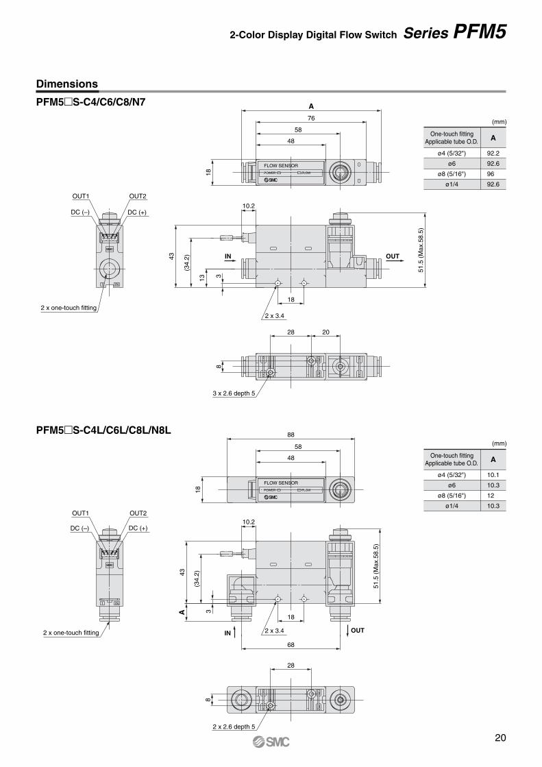
PFM5�S-C4/C6/C8/N7
(mm)
One-touch fittingApplicable tube O.D.
ø4 (5/32")
ø6
ø8 (5/16")
ø1/4
A
92.2
92.6
96
92.6
PFM5�S-C4L/C6L/C8L/N8L(mm)
One-touch fittingApplicable tube O.D.
ø4 (5/32")
ø6
ø8 (5/16")
ø1/4
A
10.1
10.3
12
10.3
1 IN
DC (+)DC (–)
OUT2OUT1
2 x one-touch fitting
1 IN
DC (–)
OUT1
DC (+)
OUT2
2 x one-touch fitting
51.5
(M
ax.5
8.5)
13
(34.
2)
3
10.2
43
18
2 x 3.4
IN OUT
18
48
58
76
A
FLOW SENSOR
POWER FLOW
10.2
3
(34.
2)
A43
18
68
51.5
(M
ax.5
8.5)
2 x 3.4IN OUT
18
48
58
88
FLOW SENSOR
POWER FLOW
28 20
8
3 x 2.6 depth 5
2 x 2.6 depth 5
28
8
Dimensions
20
2-Color Display Digital Flow Switch Series PFM5
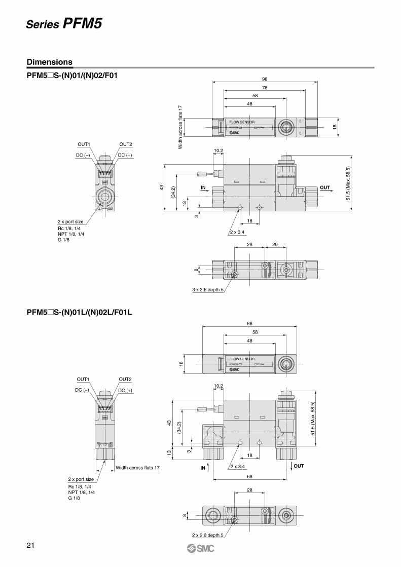
PFM5�S-(N)01/(N)02/F01
PFM5�S-(N)01L/(N)02L/F01L
1 IN
Width across flats 17
DC (+)DC (–)
OUT2OUT1
2 x port size
Rc 1/8, 1/4NPT 1/8, 1/4G 1/8
10.2
3
(34.
2)
18
68
1343
51.5
(M
ax. 5
8.5)
2 x 3.4IN OUT
1 IN
DC (–)
OUT1 OUT2
DC (+)
2 x port size
Rc 1/8, 1/4NPT 1/8, 1/4G 1/8
18
13
(34.
2)43
10.2
51.5
(M
ax. 5
8.5)
3
2 x 3.4
IN OUT
18
48
58
76
98
Wid
th a
cros
s fla
ts 1
7
FLOW SENSOR
POWER FLOW
48
58
88
18
FLOW SENSOR
POWER FLOW
28 20
8
3 x 2.6 depth 5
2 x 2.6 depth 5
28
8
Dimensions
21
Series PFM5
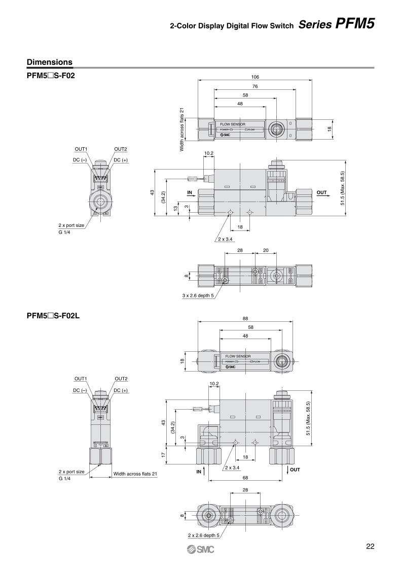
PFM5�S-F02
PFM5�S-F02L
1 IN
Width across flats 212 x port size
OUT2
DC (+)DC (–)
OUT1
G 1/4
51.5
(M
ax. 5
8.5)
68
2 x 3.4
181743
3
(34.
2)
10.2
IN OUT
1 IN
2 x port size
G 1/4
OUT2
DC (+)
OUT1
DC (–)
2 x 3.4
51.5
(M
ax. 5
8.5)
10.2
18
43
13
(34.
2)
3IN OUT
Wid
th a
cros
s fla
ts 2
1
106
76
58
48
18
FLOW SENSOR
POWER FLOW
18
88
58
48
FLOW SENSOR
POWER FLOW
28 20
8
3 x 2.6 depth 5
28
8
2 x 2.6 depth 5
Dimensions
22
2-Color Display Digital Flow Switch Series PFM5
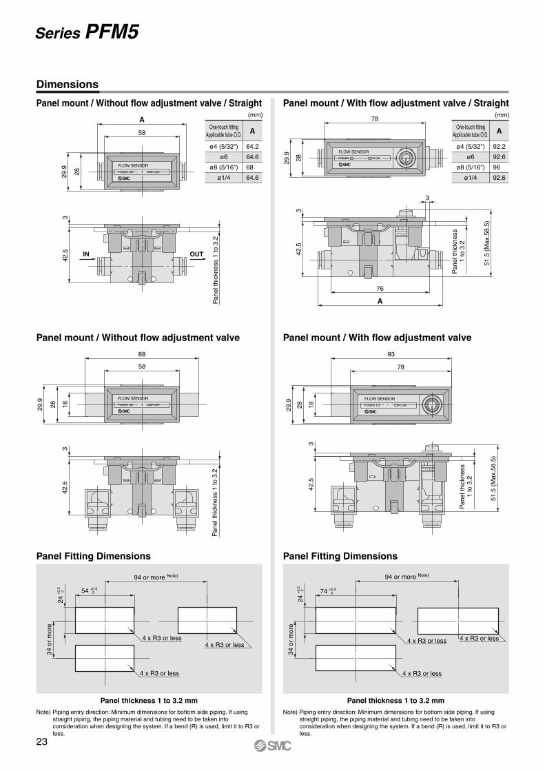
OUT
Pan
el th
ickn
ess
1 to
3.2
42.5
3
IN
3
Pan
el th
ickn
ess
1 to
3.2
51.5
(M
ax.5
8.5)
76
A42
.53
42.5
3
Pan
el th
ickn
ess
1 to
3.2
51.5
(M
ax.5
8.5)
342
.5
Pan
el th
ickn
ess
1 to
3.2
Panel mount / Without flow adjustment valve / Straight Panel mount / With flow adjustment valve / Straight
Panel mount / Without flow adjustment valve Panel mount / With flow adjustment valve
(mm)
One-touch fittingApplicable tube O.D.
ø4 (5/32")
ø6
ø8 (5/16")
ø1/4
A
92.2
92.6
96
92.6
(mm)
One-touch fittingApplicable tube O.D.
ø4 (5/32")
ø6
ø8 (5/16")
ø1/4
A
64.2
64.6
68
64.6
78
2829.9
FLOW SENSOR
POWER FLOW
A
58
2829.9
FLOW SENSOR
POWER FLOW
29.9
28 18
88
58
FLOW SENSOR
POWER FLOW
93
78
182829.9
FLOW SENSOR
POWER FLOW
Dimensions
Note) Piping entry direction: Minimum dimensions for bottom side piping. If using straight piping, the piping material and tubing need to be taken into consideration when designing the system. If a bend (R) is used, limit it to R3 or less.
Panel Fitting Dimensions
Panel thickness 1 to 3.2 mm
Note) Piping entry direction: Minimum dimensions for bottom side piping. If using straight piping, the piping material and tubing need to be taken into consideration when designing the system. If a bend (R) is used, limit it to R3 or less.
Panel Fitting Dimensions
Panel thickness 1 to 3.2 mm
94 or more Note)
74 +0.50
34 o
r m
ore
24+
0.5
0
94 or more Note)
54 +0.50
34 o
r m
ore
24+
0.5
0
4 x R3 or less
4 x R3 or less
4 x R3 or less 4 x R3 or less
4 x R3 or less
4 x R3 or less
23
Series PFM5
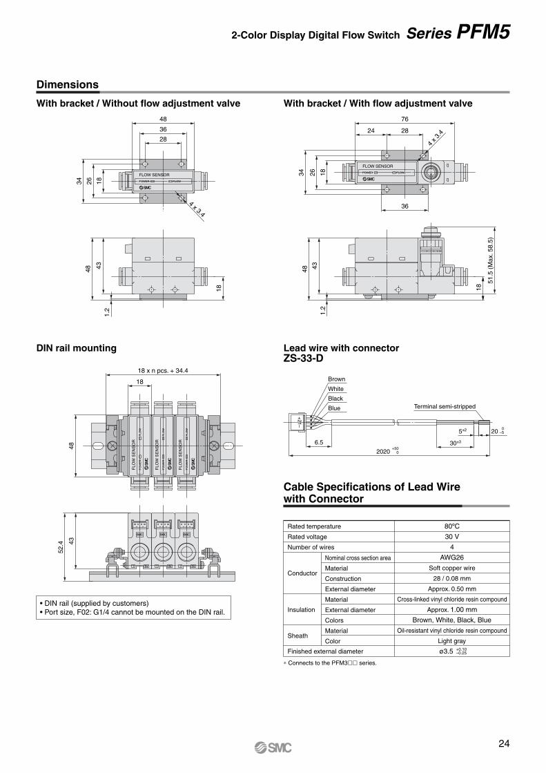
11IN1 IN IN
43
52.4
431.
2
48
18
1.2
51.5
(M
ax. 5
8.5)
18
4348
With bracket / Without flow adjustment valve With bracket / With flow adjustment valve
DIN rail mounting
Cable Specifications of Lead Wire with Connector
∗ Connects to the PFM3�� series.
Insulation
Finished external diameter
Nominal cross section area
Material
Construction
External diameter
Material
External diameter
Colors
Material
Color
Rated temperature
Rated voltage
Number of wires
Conductor
Sheath
80ºC
30 V
4
AWG26
Soft copper wire
28 / 0.08 mm
Approx. 0.50 mm
Cross-linked vinyl chloride resin compound
Approx. 1.00 mm
Brown, White, Black, Blue
Oil-resistant vinyl chloride resin compound
Light gray
ø3.5 +0.10–0.25
5±2
Brown
White
Black
Blue
6.5
+21–
2020+50
0
200
–5
30±3
Terminal semi-stripped
Lead wire with connectorZS-33-D
48
36
28
34 26 18
4 x 3.4
FLOW SENSOR
POWER FLOW
34 26 18
24 28
76
4 x 3
.4
36
FLOW SENSOR
POWER FLOW
18 x n pcs. + 34.4
18
48
FLO
W S
EN
SO
R
PO
WE
RF
LOW
FLO
W S
EN
SO
R
PO
WE
RF
LOW
FLO
W S
EN
SO
R
PO
WE
RF
LOW
Dimensions
• DIN rail (supplied by customers)• Port size, F02: G1/4 cannot be mounted on the DIN rail.
24
2-Color Display Digital Flow Switch Series PFM5
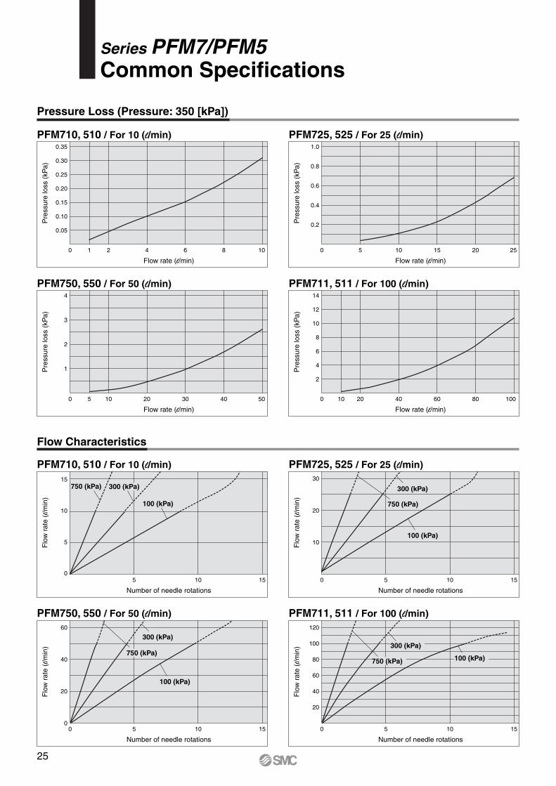
Pressure Loss (Pressure: 350 [kPa])
Flow Characteristics
PFM710, 510 / For 10 (l/min)
Pre
ssur
e lo
ss (
kPa)
0.35
0.30
0.25
0.20
0.15
0.10
0.05
Flow rate (l/min)
1 2 4 6 8 100
PFM750, 550 / For 50 (l/min)
Pre
ssur
e lo
ss (
kPa)
4
3
2
1
Flow rate (l/min)
5 10 20 30 40 500
PFM711, 511 / For 100 (l/min)
PFM725, 525 / For 25 (l/min)
Pre
ssur
e lo
ss (
kPa)
1.0
0.8
0.6
0.4
0.2
Flow rate (l/min)
5 10 15 20 250
Pre
ssur
e lo
ss (
kPa)
14
12
10
8
6
4
2
Flow rate (l/min)
10 20 40 60 80 1000
PFM725, 525 / For 25 (l/min)
PFM711, 511 / For 100 (l/min)
Series PFM7/PFM5Common Specifications
PFM710, 510 / For 10 (l/min)
PFM750, 550 / For 50 (l/min)60
40
20
05 10 150
Flo
w r
ate
(l/m
in)
Number of needle rotations
750 (kPa)
300 (kPa)
100 (kPa)
Flo
w r
ate
(l/m
in)
Number of needle rotations
120
100
80
60
40
20
5 10 150
750 (kPa)
300 (kPa)
100 (kPa)
Flo
w r
ate
(l/m
in)
Number of needle rotations
30
20
10
5 10 150
750 (kPa)
300 (kPa)
100 (kPa)
Flo
w r
ate
(l/m
in)
Number of needle rotations
15
10
5
05 10 15
750 (kPa) 300 (kPa)
100 (kPa)
25
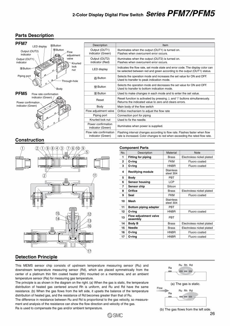
Parts Description
Construction
Detection Principle
2
IN
1S
Output (OUT1) indicator
Output (OUT2) indicator
Button
Button
ButtonLED display
Flow adjustment valve
Knurled lock nut
Piping port
Body
Through-hole
This MEMS sensor chip consists of upstream temperature measuring sensor (Ru) and downstream temperature measuring sensor (Rd), which are placed symmetrically from the center of a platinum thin film coated heater (Rh) mounted on a membrane, and an ambient temperature sensor (Ra) for measuring gas temperature.The principle is as shown in the diagram on the right. (a) When the gas is static, the temperature distribution of heated gas centered around Rh is uniform, and Ru and Rd have the same resistance. (b) When the gas flows from the left side, it upsets the balance of the temperature distribution of heated gas, and the resistance of Rd becomes greater than that of Ru.The difference in resistance between Ru and Rd is proportional to the gas velocity, so measure-ment and analysis of the resistance can show the flow direction and velocity of the gas.Ra is used to compensate the gas and/or ambient temperature.
RaRu Rh Rd
RaRu Rh Rd
Flow
(b) The gas flows from the left side.
(a) The gas is static.
Component Parts
!1
!5 !2
!3
!6
!7
!4
q w
w
qoire uy!0 ot
PFM7
PFM5
Illuminates when the output (OUT1) is turned on.Flashes when overcurrent error occurs.
Description
Output (OUT1)indicator (Green)
Item
Illuminates when the output (OUT2) is turned on.Flashes when overcurrent error occurs.
Output (OUT2)indicator (Red)
Indicates the flow rate, set mode state and error code. The display color can be selected between red and green according to the output (OUT1) status.
LED display
Selects the operation mode and increases the set value for ON and OFF.Used to transfer to peak indication mode.
Selects the operation mode and decreases the set value for ON and OFF.Used to transfer to bottom indication mode.
Used to make changes in each mode and to enter the set value.
Reset function is activated by pressing � and � buttons simultaneously. Returns the indicated value to zero and clears errors.
Flashing interval changes according to flow rate. Flashes faster when flow rate is increased. Color changes to red when exceeding the rated flow rate.
Reset
Main body of the flow switchBody
Orifice mechanism to adjust the flow rateFlow adjustment valve
Connection port for pipingPiping port
Flow rate confirmationindicator (Green)
Used to fix the needle.Knurled lock nut
Illuminates when power is supplied.Power confirmationindicator (Green)
Button
Button
Button
Flow rate confirmation indicator (Green)
Power confirmation indicator (Green)
Fitting for piping
O-ring
O-ring
Rectifying module
Body
Sensor housing
Sensor chip
Orifice
Seal
Mesh
Bottom piping adapter
O-ring
Flow adjustment valve assembly
Body B
Needle
O-ring
O-ring
No. Description Note
1
2
3
4
5
6
7
8
9
10
11
12
13
14
15
16
17
Electroless nickel plated
Fluoro coated
Fluoro coated
Electroless nickel plated
Fluoro coated
Fluoro coated
Electroless nickel plated
Electroless nickel plated
Fluoro coated
Fluoro coated
Material
Brass
FKM
HNBR
PBT
LCP
Silicon
Brass
FKM
PBT
HNBR
PBT
Brass
Brass
HNBR
HNBR
Stainlesssteel 304
Stainlesssteel 304
26
2-Color Display Digital Flow Switch Series PFM7/PFM5
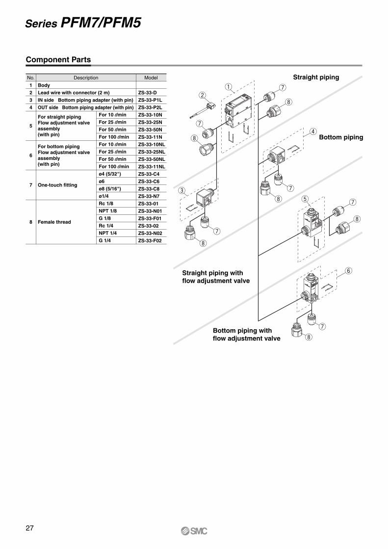
t u
i
u
i
y
qw
u
i
e
r
i
u
i
u
i
u
Straight piping
Bottom piping
Straight piping withflow adjustment valve
Bottom piping withflow adjustment valve
Component Parts
Body
Lead wire with connector (2 m)
IN side Bottom piping adapter (with pin)
OUT side Bottom piping adapter (with pin)
For straight pipingFlow adjustment valve assembly(with pin)
For bottom pipingFlow adjustment valve assembly(with pin)
One-touch fitting
Female thread
No. Description
ZS-33-D
ZS-33-P1L
ZS-33-P2L
ZS-33-10N
ZS-33-25N
ZS-33-50N
ZS-33-11N
ZS-33-10NL
ZS-33-25NL
ZS-33-50NL
ZS-33-11NL
ZS-33-C4
ZS-33-C6
ZS-33-C8
ZS-33-N7
ZS-33-01
ZS-33-N01
ZS-33-F01
ZS-33-02
ZS-33-N02
ZS-33-F02
For 10 l/min
For 25 l/min
For 50 l/min
For 100 l/min
For 10 l/min
For 25 l/min
For 50 l/min
For 100 l/min
ø4 (5/32")
ø6
ø8 (5/16")
ø1/4
Rc 1/8
NPT 1/8
G 1/8
Rc 1/4
NPT 1/4
G 1/4
Model
1
2
3
4
5
6
7
8
27
Series PFM7/PFM5
Series PFMFunction Details
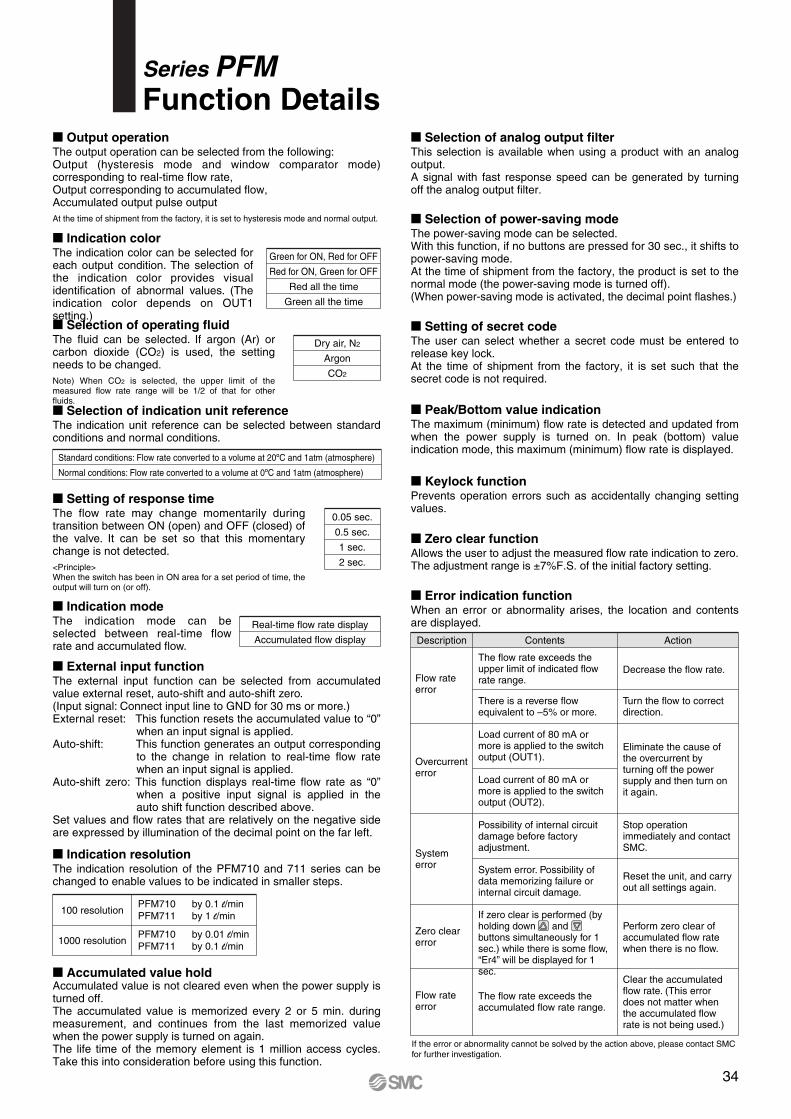
� Indication colorThe indication color can be selected for each output condition. The selection of the indication color provides visual identification of abnormal values. (The indication color depends on OUT1 setting.)� Selection of operating fluidThe fluid can be selected. If argon (Ar) or carbon dioxide (CO2) is used, the setting needs to be changed.Note) When CO2 is selected, the upper limit of the measured flow rate range will be 1/2 of that for other fluids.
� Indication modeThe indication mode can be selected between real-time flow rate and accumulated flow.
Real-time flow rate display
Accumulated flow display
Dry air, N2
Argon
CO2
Green for ON, Red for OFF
Red for ON, Green for OFF
Red all the time
Green all the time
0.05 sec.
0.5 sec.
1 sec.
2 sec.
� Setting of response timeThe flow rate may change momentarily during transition between ON (open) and OFF (closed) of the valve. It can be set so that this momentary change is not detected. <Principle>When the switch has been in ON area for a set period of time, the output will turn on (or off).
Standard conditions: Flow rate converted to a volume at 20ºC and 1atm (atmosphere)
Normal conditions: Flow rate converted to a volume at 0ºC and 1atm (atmosphere)
If the error or abnormality cannot be solved by the action above, please contact SMC for further investigation.
Description Contents Action
Flow rate error
The flow rate exceeds the upper limit of indicated flow rate range.
Decrease the flow rate.
There is a reverse flow equivalent to –5% or more.
Turn the flow to correct direction.
Overcurrenterror
System error
Zero clear error
Flow rate error
Load current of 80 mA or more is applied to the switch output (OUT1).
Possibility of internal circuit damage before factory adjustment.
Stop operation immediately and contact SMC.
System error. Possibility of data memorizing failure or internal circuit damage.
Reset the unit, and carry out all settings again.
Load current of 80 mA or more is applied to the switch output (OUT2).
Eliminate the cause of the overcurrent by turning off the power supply and then turn on it again.
Perform zero clear of accumulated flow rate when there is no flow.
If zero clear is performed (by holding down and buttons simultaneously for 1 sec.) while there is some flow, “Er4” will be displayed for 1 sec.
The flow rate exceeds the accumulated flow rate range.
Clear the accumulated flow rate. (This error does not matter when the accumulated flow rate is not being used.)
� Selection of indication unit referenceThe indication unit reference can be selected between standard conditions and normal conditions.
� External input functionThe external input function can be selected from accumulated value external reset, auto-shift and auto-shift zero.(Input signal: Connect input line to GND for 30 ms or more.)External reset: This function resets the accumulated value to “0”
when an input signal is applied.Auto-shift: This function generates an output corresponding
to the change in relation to real-time flow rate when an input signal is applied.
Auto-shift zero: This function displays real-time flow rate as “0” when a positive input signal is applied in the auto shift function described above.
Set values and flow rates that are relatively on the negative side are expressed by illumination of the decimal point on the far left.
� Indication resolutionThe indication resolution of the PFM710 and 711 series can be changed to enable values to be indicated in smaller steps.
� Accumulated value holdAccumulated value is not cleared even when the power supply is turned off.The accumulated value is memorized every 2 or 5 min. during measurement, and continues from the last memorized value when the power supply is turned on again. The life time of the memory element is 1 million access cycles. Take this into consideration before using this function.
100 resolutionPFM710 by 0.1 l/minPFM711 by 1 l/min
1000 resolutionPFM710 by 0.01 l/minPFM711 by 0.1 l/min
� Output operationThe output operation can be selected from the following:Output (hysteresis mode and window comparator mode) corresponding to real-time flow rate,Output corresponding to accumulated flow,Accumulated output pulse outputAt the time of shipment from the factory, it is set to hysteresis mode and normal output.
� Error indication functionWhen an error or abnormality arises, the location and contents are displayed.
� Peak/Bottom value indicationThe maximum (minimum) flow rate is detected and updated from when the power supply is turned on. In peak (bottom) value indication mode, this maximum (minimum) flow rate is displayed.
� Keylock functionPrevents operation errors such as accidentally changing setting values.
� Zero clear functionAllows the user to adjust the measured flow rate indication to zero. The adjustment range is ±7%F.S. of the initial factory setting.
� Setting of secret codeThe user can select whether a secret code must be entered to release key lock.At the time of shipment from the factory, it is set such that the secret code is not required.
� Selection of power-saving modeThe power-saving mode can be selected.With this function, if no buttons are pressed for 30 sec., it shifts to power-saving mode.At the time of shipment from the factory, the product is set to the normal mode (the power-saving mode is turned off).(When power-saving mode is activated, the decimal point flashes.)
� Selection of analog output filterThis selection is available when using a product with an analog output.A signal with fast response speed can be generated by turning off the analog output filter.
34
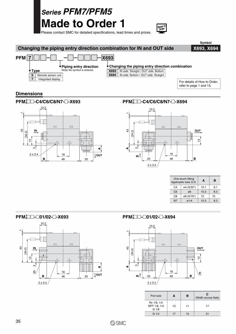
Series PFM7/PFM5Made to Order 1Please contact SMC for detailed specifications, lead times and prices.
Changing the piping entry direction combination for IN and OUT side
Dimensions
PFM ��-C4/C6/C8/N7-�-X694
PFM ��-�01/02-�-X693 PFM ��-�01/02-�-X694
PFM 7 X693
Piping entry directionNote) No symbol is entered. IN side: Straight / OUT side: Bottom
IN side: Bottom / OUT side: StraightX693X694
Changing the piping entry direction combination
Remote sensor unitIntegrated display
57
Type
IN
2 x 3.4
13
A43
1
(34.
2)
3
OUT
B
18
4820
10.2
IN
OUT2 x 3.4
10.2
143
(34.
2)13
3
B 48 20
18
A
IN
OUT
2 x 3.4
C
A
2048
18
B
3
13
(34.
2)431
10.2
OUT
2 x 3.4
B48
18
20IN
13
3A43
(34.
2)
1
10.2
C
One-touch fittingApplicable tube O.D.
C4
C6
C8
N7
ø4 (5/32")
ø6
ø8 (5/16")
ø1/4
A
10.1
10.3
12
10.3
B
8.1
8.3
10
8.3
Port size
Rc 1/8, 1/4NPT 1/8, 1/4
G 1/8
G 1/4
A
13
17
B
11
15
C(Width across flats)
17
21
PFM ��-C4/C6/C8/N7-�-X69375
75
75
75
For details of How to Order,refer to page 1 and 13.
X693, X694Symbol
35
Dimensions
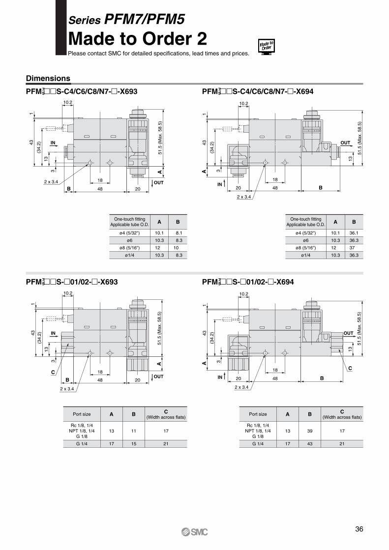
PFM ��S-C4/C6/C8/N7-�-X693 PFM ��S-C4/C6/C8/N7-�-X694
PFM ��S-�01/02-�-X693 PFM ��S-�01/02-�-X694
OUT
IN
2 x 3.4
51.5
(M
ax. 5
8.5)
13
B4820
18
3(3
4.2)43
1A
10.2
OUT
IN
2 x 3.4
A51
.5 (
Max
. 58.
5)
2048
18
B
3
13
(34.
2)431
10.2
One-touch fittingApplicable tube O.D.
ø4 (5/32")
ø6
ø8 (5/16")
ø1/4
A
10.1
10.3
12
10.3
B
8.1
8.3
10
8.3
One-touch fittingApplicable tube O.D.
ø4 (5/32")
ø6
ø8 (5/16")
ø1/4
A
10.1
10.3
12
10.3
B
36.1
36.3
37
36.3
Port size
Rc 1/8, 1/4NPT 1/8, 1/4
G 1/8
G 1/4
A
13
17
B
11
15
C(Width across flats)
17
21
Port size
Rc 1/8, 1/4NPT 1/8, 1/4
G 1/8
G 1/4
A
13
17
B
39
43
C(Width across flats)
17
21
IN
OUT
2 x 3.4
51.5
(M
ax. 5
8.5)
13
B4820
18
3
(34.
2)431
A
10.2
C
OUT
IN
2 x 3.4
A51
.5 (
Max
. 58.
5)
2048B
18
3
13
(34.
2)431
10.2
C
75
75
75
75
Series PFM7/PFM5Made to Order 2Please contact SMC for detailed specifications, lead times and prices.
36
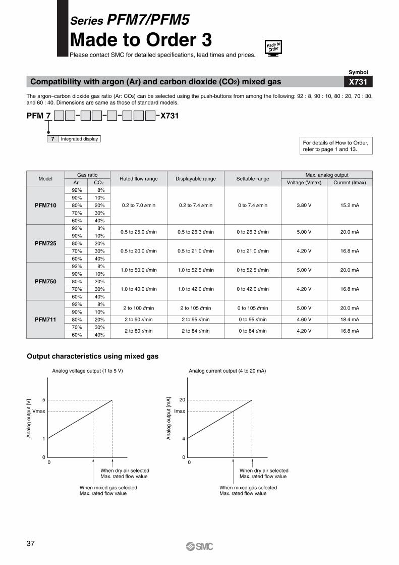
Compatibility with argon (Ar) and carbon dioxide (CO2) mixed gas
PFM 7 X731
Integrated display7
X731Symbol
The argon–carbon dioxide gas ratio (Ar: CO2) can be selected using the push-buttons from among the following: 92 : 8, 90 : 10, 80 : 20, 70 : 30, and 60 : 40. Dimensions are same as those of standard models.
Gas ratioModel
PFM710
Rated flow range Displayable rangeAr
92%
90%
80%
70%
60%
92%
90%
80%
70%
60%
92%
90%
80%
70%
60%
92%
90%
80%
70%
60%
8%
10%
20%
30%
40%
8%
10%
20%
30%
40%
8%
10%
20%
30%
40%
8%
10%
20%
30%
40%
0.2 to 7.0 l/min
0.5 to 25.0 l/min
0.5 to 20.0 l/min
1.0 to 50.0 l/min
1.0 to 40.0 l/min
2 to 100 l/min
2 to 90 l/min
2 to 80 l/min
0.2 to 7.4 l/min
0.5 to 26.3 l/min
0.5 to 21.0 l/min
1.0 to 52.5 l/min
1.0 to 42.0 l/min
2 to 105 l/min
2 to 95 l/min
2 to 84 l/min
PFM725
PFM750
PFM711
CO2Settable range
Max. analog output
Voltage (Vmax) Current (Imax)
0 to 7.4 l/min
0 to 26.3 l/min
0 to 21.0 l/min
0 to 52.5 l/min
0 to 42.0 l/min
0 to 105 l/min
0 to 95 l/min
0 to 84 l/min
3.80 V
5.00 V
4.20 V
5.00 V
4.20 V
5.00 V
4.60 V
4.20 V
15.2 mA
20.0 mA
16.8 mA
20.0 mA
16.8 mA
20.0 mA
18.4 mA
16.8 mA
Analog voltage output (1 to 5 V)
5
Vmax
1
00 0
When dry air selectedMax. rated flow value
When mixed gas selectedMax. rated flow value
Analog current output (4 to 20 mA)
20
Imax
4
0
When dry air selectedMax. rated flow value
When mixed gas selectedMax. rated flow value
Output characteristics using mixed gas
Series PFM7/PFM5Made to Order 3Please contact SMC for detailed specifications, lead times and prices.
For details of How to Order,refer to page 1 and 13.
Ana
log
outp
ut [V
]
Ana
log
outp
ut [m
A]
37