REMAINING LIFE ASSESSMENT OF A HIGH PRESSURE TURBINE...
12
Baki}, G. M., et al., Remaining Life Assessment of a High Pressure Turbine… THERMAL SCIENCE: Year 2013, Vol. 17, Suppl. 1, pp. S127-S138 S127 REMAINING LIFE ASSESSMENT OF A HIGH PRESSURE TURBINE CASING IN CREEP AND LOW CYCLE SERVICE REGIME by Gordana M. BAKI] *a , Vera M. ŠIJA^KI-ŽERAVI] a , Miloš B. DJUKI] a , Bratislav M. RAJI^I] a , and Marko M. TASI] a a Faculty of Mechanical Engineering, University of Belgrade, Belgrade, Serbia. Original scientific paper DOI: 10.2298/TSCI121219179B Thick walled components such as high pressure (HP) steam turbine casings operating under high parameter conditions are subjected to a complex stress state. As a result of that stress state, some parts of HP turbine casing undergo to the creep fatigue caused by the combination of thermal fatigue resulted from repeated start/stop operation and the creep which occurs during long-term operation at high temperature and high-pressure. It is well known that domestic thermal power plants have been in use over 100000 h which means that significant cost is required not only for maintenance, but often for renewal of equipment. Based on comprehensive investigation, the results of residual life assessment of one high pressure steam turbine casing, which belongs to the older turbine generation, taking into account simultaneous action of thermal fatigue and creep, are presented in this paper. Also, the critical flaw crack size of HP turbine casing is determined because this parameter has a strong influence on casing integrity and residual life. The results of residual life assessment provide not only a basis for further maintenance, but also estimated time for reparation or renewal. Key words: remaining life assessment, creep-fatigue interaction, high pressure steam turbine casing Introduction Turbines of thermal power plants are, like other power plant components, designed for a specific length of service life. Older generations of turbines that were made during the middle of the past century were designed for 100000 service hours. It was recommended, after this period has passed, to check the state of vital turbine elements and to assess the previous exhaustion and risk of further work for a significantly longer period (e.g. 200000 h) [1, 2]. The practice of service life extending is common around the world, not only for economic reasons, but also because the risks are generally reduced with the advancement of knowledge in the areas of metallurgy, strength, dynamics and fracture mechanics. Also, significant contribution to safe maintenance and work of older turbine facilities is provided by data about exploitation of these and similar facilities. Components working at high temperatures, such as elements of high pressure turbines, are exposed to extreme operating conditions and a complex temperature-stress state during exploitation [1-4]. Hence, it is * Corresponding author, e-mail:[email protected]
-
Upload
truongnguyet -
Category
Documents
-
view
222 -
download
4
Transcript of REMAINING LIFE ASSESSMENT OF A HIGH PRESSURE TURBINE...
Baki}, G. M., et al., Remaining Life Assessment of a High Pressure Turbine… THERMAL SCIENCE: Year 2013, Vol. 17, Suppl. 1, pp. S127-S138 S127
REMAINING LIFE ASSESSMENT OF A HIGH PRESSURE TURBINE CASING IN CREEP AND LOW CYCLE SERVICE REGIME
by
Gordana M. BAKI]*a, Vera M. ŠIJA^KI-ŽERAVI]a, Miloš B. DJUKI]a, Bratislav M. RAJI^I]a, and Marko M. TASI]a
aFaculty of Mechanical Engineering, University of Belgrade, Belgrade, Serbia.
Original scientific paper DOI: 10.2298/TSCI121219179B
Thick walled components such as high pressure (HP) steam turbine casings operating under high parameter conditions are subjected to a complex stress state. As a result of that stress state, some parts of HP turbine casing undergo to the creep fatigue caused by the combination of thermal fatigue resulted from repeated start/stop operation and the creep which occurs during long-term operation at high temperature and high-pressure. It is well known that domestic thermal power plants have been in use over 100000 h which means that significant cost is required not only for maintenance, but often for renewal of equipment. Based on comprehensive investigation, the results of residual life assessment of one high pressure steam turbine casing, which belongs to the older turbine generation, taking into account simultaneous action of thermal fatigue and creep, are presented in this paper. Also, the critical flaw crack size of HP turbine casing is determined because this parameter has a strong influence on casing integrity and residual life. The results of residual life assessment provide not only a basis for further maintenance, but also estimated time for reparation or renewal. Key words: remaining life assessment, creep-fatigue interaction, high pressure
steam turbine casing
Introduction
Turbines of thermal power plants are, like other power plant components, designed for a specific length of service life. Older generations of turbines that were made during the middle of the past century were designed for 100000 service hours. It was recommended, after this period has passed, to check the state of vital turbine elements and to assess the previous exhaustion and risk of further work for a significantly longer period (e.g. 200000 h) [1, 2]. The practice of service life extending is common around the world, not only for economic reasons, but also because the risks are generally reduced with the advancement of knowledge in the areas of metallurgy, strength, dynamics and fracture mechanics. Also, significant contribution to safe maintenance and work of older turbine facilities is provided by data about exploitation of these and similar facilities. Components working at high temperatures, such as elements of high pressure turbines, are exposed to extreme operating conditions and a complex temperature-stress state during exploitation [1-4]. Hence, it is
*Corresponding author, e-mail:[email protected]
Baki}, G. M., et al., Remaining Life Assessment of a High Pressure Turbine… S128 THERMAL SCIENCE: Year 2013, Vol. 17, Suppl. 1, pp. S127-S138
common practice to calculate remaining life in terms of creep and occurrence of damage over time, low-cycle fatigue and critical crack size. This approach is important since the studies have shown [5] that high and medium pressure turbine elements are responsible for the highest losses in energy production of thermal power plants, caused by turbine installation system failure. Knowledge about the state of the system, obtained by regular testing, is necessary to calculate the remaining life of steam turbines. The assessment of remaining life of steam turbines requires certain input data [6], such as basic information from technical documentation, operating data (temperature, pressure, vibrations, number and type of starts, working fluid quality, data about work irregularities), data about the state of metal, which is typically obtained by non-destructive testing, etc. The result of such an approach is a recommendation for continued safe work of turbine elements during a specified period, or for replacement /repair of certain components. The assessment of remaining life of a high pressure turbine casing of fossil fuel thermal power plant of 210 MW after 150000 h of service in terms of combined effect of creep and low-cycle fatigue is presented here.
Background
Assessment of remaining life given in this paper was performed according to different criteria and methods as a function of work parameters and types of load applied to high pressure turbine casing (HP turbine) of an installation with power of 210 MW. Turbine installation of Russian manufacturing type LMZ-K200-130 belongs to the older generation of structures and consists of high, medium and low pressure turbines. HP turbine casing was made of a cast steel, grade 1.25Cr1Mo0.3V (designation according to GOST: 15H1M1FL) and basic information about it, according to the manufacturer’s data, are given in table 1.
Table 1: Basic information about the HP turbine
Basic information Value
Rotor speed, rpm 3000
Fresh steam pressure inlet of stop valves, MPa 13
Fresh steam temperature inlet of stop valves, °C 540
Design steam flow at 210 MW, t/h 628
Maximum steam flow through a turbine, t/h 655
Outlet steam pressure of HP turbine, for design flow, Mpa 2.78
Outlet steam temperature of HP turbine, °C 333
Relevant casing wall thickness, mm 90
After 150000 service hours, non-destructive testing detected cracks at the HP casing entrance and due to this, it was necessary to perform the assessment of its remaining life and give recommendations for further safe service taking into account the presence of cracks. Because of the effect of low-cycle fatigue on loss of working resources it should be pointed out that, by the time the assessment was made, the entire installation had 378 hot (of 260°C) and 101 cold starts. Mode of starting, i.e. the average maximal temperature growth rate of metal, given in manufacturer’s instructions, is shown in table 2.
Baki}, G. M., et al., Remaining Life Assessment of a High Pressure Turbine… THERMAL SCIENCE: Year 2013, Vol. 17, Suppl. 1, pp. S127-S138 S129
Remaining life assessment methodology
During the calculation of turbine components that work at increased temperatures, >400°C, material damage caused by creep conditions and conditions caused by low-cycle fati¬gue need to be taken into consideration [1, 4-8]. Taking into account the simultaneous acting of these two damage mechanisms, it is necessary to sum their effects, which is, in case of turbine elements, most frequently performed by applying linear theory of damage accumulation. Hot and cold starts, change of load during service, change of steam pressure or rotor speed have the highest influence on the appearance of low-cycle fatigue, while different levels of static loads and temperatures cause damage over time – creep. It should be pointed out that, in terms of component safety operation, total fatigue of metal, calculated as a sum of effects of these two damage mechanisms should not exceed 75% of its total resource.
Table 2: Temperature growth rate of metal in HP turbines according to manufacturer’s instructions
Temperature range, T [C] 100-200 200-300 300-400 400-500 500
Temperature rate, °C/min 4 3 2 1 0.6
Basic input data for exhaustion calculation are stress and temperature, as well as data
about chemical and physical properties of the material. Stresses induced by inner pressure of steam, centrifugal forces or thermal effects for complex configurations of machine elements today is most often determined using finite element method. Because of that, a valid assessment of stress levels requires knowledge of real operation parameters. One of the approaches to assessing the used life, i.e. the exhaustion of material component under combined effects of fatigue and creep is to apply the rule of life fractions, i.e. a simple relation that combines Miner’s rule of life fraction under fatigue ((nij/Nij)=1) and Robinson’s rule of life fractions under creep ((tij/ij)=1) 1,3,5-8:
1ij
ij
ij
ij t
N
n
(1)
where: nij is the number of cycles at temperature i and stress j; Nij is the number of cycles to failure at temperature i and stress j; tijis the service time at temperature i and stress j; ij is time to failure during creep at temperature i and stress j. This rule, in general, has been experimentally confirmed for a number of cycles up to 105 [9,10]. However, despite this approach enabling first steps toward including inter-crystalline and transcrystalline fractures in explaining the occurrence of damage under creep and fatigue conditions, one of its main flaws is that it cannot take into account the strain that appears during stress relaxation prior to increased creep [1,9,10]. However, in case of cast components, such as turbine casings, strain caused by creep at the time of failure is negligible. Having in mind that, according to data obtained from practice [1], a regular cold start causes levels of damage about three times higher that the hot start, the equivalent number of starts can be applied for determining of exhaustion level.
hotcoldcoldeq NNNN 3
1 (2)
Total exhaustion, Iu, is obtained from expression 1, by summing exhaustion from creep, Icand from fatigue, If, by applying equation 2:
Baki}, G. M., et al., Remaining Life Assessment of a High Pressure Turbine… S130 THERMAL SCIENCE: Year 2013, Vol. 17, Suppl. 1, pp. S127-S138
Iu= Ic+ If = (tij/ij) + neq/Neq (3)
In general, calculation of criticality and propagation of cracks on rotors, disks and turbine casings is performed based on fracture mechanics theory, whereby in this case linear theory of damage accumulation due to the effects of various load types and levels is used.
cIc acK (4)
where: K1c represents fracture toughness (MPa∙m1/2); is the stress, MPa; ac is the critical crack depth, m; c is a factor that depends on the shape of the crack. Stable crack growth rate is dependent from many factors [4,10-12], hence cycle load is determined according to Paris law, which, in case of existence of a crack with length a, can be described by eq. 5.
fm
f acCdn
da (5)
where: da is the crack size increment, m; dn is a single cycle; is the stress increment, MPa; Cfand mfrepresent material properties which depend on temperature and type of stress.For static loading under creep conditions, crack growth rate for length a is determined from eq. 6:
cm
c acCd
da
(6)
where:da is the crack size increment, m; dtime spent at the specific temperature, h; the operating stress, Mpa; Cc and mcmaterial properties which depend on temperature and type of stress.
Time to fracture due to creep for working stress of turbine casing is determined according to the following expression 13,14:
)log(
)log(
2log5log
53010
530102
53010
5
5
5
C
Cx
C
R
R
R
(7)
where: CR 530
105 is the creep strength at 530°C for 100000h, C
xR 530
102 5 the creep strength at 530°C for
200000h.
Basis for remaining assessment life of HP Turbine casing
As it was pointed out, the procedure of calculating the remaining life includes mode-ling of HP turbine casing, systematization of data including strength, temperatures and pressures, determining of the state of metal after 150000 h of service using non-destructive testing methods and calculation of exhaustion levels and critical crack size.
Modeling of HP turbine casing
A spatial model of upper and lower half of HP turbine casing was made using SolidWorks v.9.0 software for three-dimensional modeling. Included in SolidWorks v.9.0 software is the source code of modules for structure calculation using finite element method COSMOS, commercially named SolidWorks-Simulation. In about the last ten years it has become practical to undertake the creep analysis of components of complex shape by finite-element techniques,

Baki}, G. M., et al., Remaining Life Assessment of a High Pressure Turbine… THERMAL SCIENCE: Year 2013, Vol. 17, Suppl. 1, pp. S127-S138 S131
although a sufficiently detailed geometric representation may require a number of nodes in the region of 250000 16. The geometry of the HP turbine casing is axial symmetric, hence FEM was used for a quarter of the casing, with 279614 nodes and 183468 tet elements (3D finite elements), figure 1a). The appearance of the inner half of the casing is shown in figure 1b).
In order to define displacements and strains within the elements, second order interpolation functions were used, which enabled a more accurate idealization of curved surfaces of the casing.
Figure 1: HP turbine casing model; top – FEM quarter of casing, bottom – inner surface
Data about measuring of service temperatures of HP turbine casing
In the purpose of determining operating conditions of the high pressure turbine casing, for which the remaining service life assessment is performed, the measured operating temperatures and pressures are analyzed for a two consecutive year period (~12,000 h). The time of continuously recorded temperatures during this period is systematized into temperature intervals of T = 10°C for the sake of extrapolating onto the total service life of 150 000 h [17,18]. The same procedure was performed for pressure data but these data did not show any significant variations, except during transition regimes, a mean operating pressure value of 8.6 MPa is adopted for calculation for inlet pressure, and 2.6 MPa for outlet pressure.
Figure 2. Distribution of measuring of metal wall temperature at HP turbine casing inlet
Measuring of steam temperature at the HP turbine casing inlet is performed on four measuring locations which correspond to four entrances for fresh steam lines, along with measuring of metal casing walls in this zone. Temperature distribution is extrapolated over the total work life for metal temperature is shown in figure 2. At the casing outlet, only the steam temperature with average values of 330°C is measured.
Baki}, G. M., et al., Remaining Life Assessment of a High Pressure Turbine… S132 THERMAL SCIENCE: Year 2013, Vol. 17, Suppl. 1, pp. S127-S138
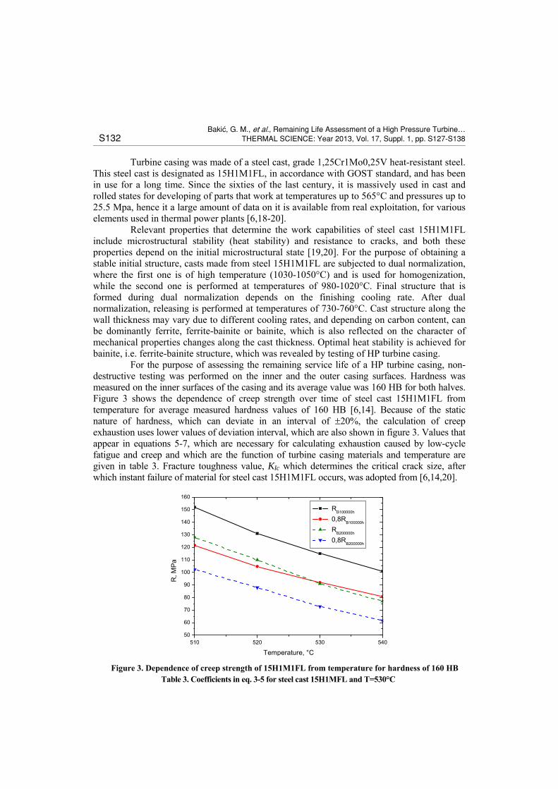
Turbine casing was made of a steel cast, grade 1,25Cr1Mo0,25V heat-resistant steel. This steel cast is designated as 15H1M1FL, in accordance with GOST standard, and has been in use for a long time. Since the sixties of the last century, it is massively used in cast and rolled states for developing of parts that work at temperatures up to 565°C and pressures up to 25.5 Mpa, hence it a large amount of data on it is available from real exploitation, for various elements used in thermal power plants [6,18-20]. Relevant properties that determine the work capabilities of steel cast 15H1M1FL include microstructural stability (heat stability) and resistance to cracks, and both these properties depend on the initial microstructural state [19,20]. For the purpose of obtaining a stable initial structure, casts made from steel 15H1M1FL are subjected to dual normalization, where the first one is of high temperature (1030-1050°C) and is used for homogenization, while the second one is performed at temperatures of 980-1020°C. Final structure that is formed during dual normalization depends on the finishing cooling rate. After dual normalization, releasing is performed at temperatures of 730-760°C. Cast structure along the wall thickness may vary due to different cooling rates, and depending on carbon content, can be dominantly ferrite, ferrite-bainite or bainite, which is also reflected on the character of mechanical properties changes along the cast thickness. Optimal heat stability is achieved for bainite, i.e. ferrite-bainite structure, which was revealed by testing of HP turbine casing. For the purpose of assessing the remaining service life of a HP turbine casing, non-destructive testing was performed on the inner and the outer casing surfaces. Hardness was measured on the inner surfaces of the casing and its average value was 160 HB for both halves. Figure 3 shows the dependence of creep strength over time of steel cast 15H1M1FL from temperature for average measured hardness values of 160 HB [6,14]. Because of the static nature of hardness, which can deviate in an interval of 20%, the calculation of creep exhaustion uses lower values of deviation interval, which are also shown in figure 3. Values that appear in equations 5-7, which are necessary for calculating exhaustion caused by low-cycle fatigue and creep and which are the function of turbine casing materials and temperature are given in table 3. Fracture toughness value, KIc which determines the critical crack size, after which instant failure of material for steel cast 15H1M1FL occurs, was adopted from [6,14,20].
Figure 3. Dependence of creep strength of 15H1M1FL from temperature for hardness of 160 HB Table 3. Coefficients in eq. 3-5 for steel cast 15H1MFL and T=530°C
510 520 530 54050
60
70
80
90
100
110
120
130
140
150
160
R, M
Pa
Temperature, °C
RB100000h
0,8RB100000h
RB200000h
0,8RB200000h

Baki}, G. M., et al., Remaining Life Assessment of a High Pressure Turbine… THERMAL SCIENCE: Year 2013, Vol. 17, Suppl. 1, pp. S127-S138 S133
Eq. 3 Eq. 4 Eq. 5
KIC, Mpam Cf mf Cc mc
60 5.8010-12 3.63 3.93610-23 9.631
Results and Discussion
Modeling the stress state caused by inner pressure in a stationary work mode enabled the obtaining of work stress distribution on inner and outer surfaces of HP casing, figure 4a-b. Maximum stresses in this case were determined on the inner surface of the casing, in the connectors opening zone. Analytically determined stress values [21] in the turbine casing wall outside this zone, caused by inner pressure at the inlet, was 72.6 Mpa, which is very close to the values obtained by FEM analysis.
Figure 4: Stress distribution in the HP casing on the inner and outer sides in stationary work mode: top – inner surface; bottom – outer surface
The effect of temperature distribution in casing walls on stress state in stationary operation mode was also analyzed. The software that was used offered the possibility of analyzing temperature fields for stationary and non-stationary heat conduction. Based on the known temperature fields, corresponding thermal stresses can be determined within the structure. During the analysis of thermal stresses in this case, boundary conditions were introduced for stationary heat conduction taking into account the input and output temperatures of metal walls at the inlet, and having in mind that the outer surfaces is isolated.
Wall temperatures of remaining inner surfaces were defined using linear interpolation and are within range of 308-540°C. Wall temperature changes from 540°C on inner walls (input steam temperature) to 530°C on the outer surface of the casing in the same zone (contact with isolation).

Baki}, G. M., et al., Remaining Life Assessment of a High Pressure Turbine… S134 THERMAL SCIENCE: Year 2013, Vol. 17, Suppl. 1, pp. S127-S138
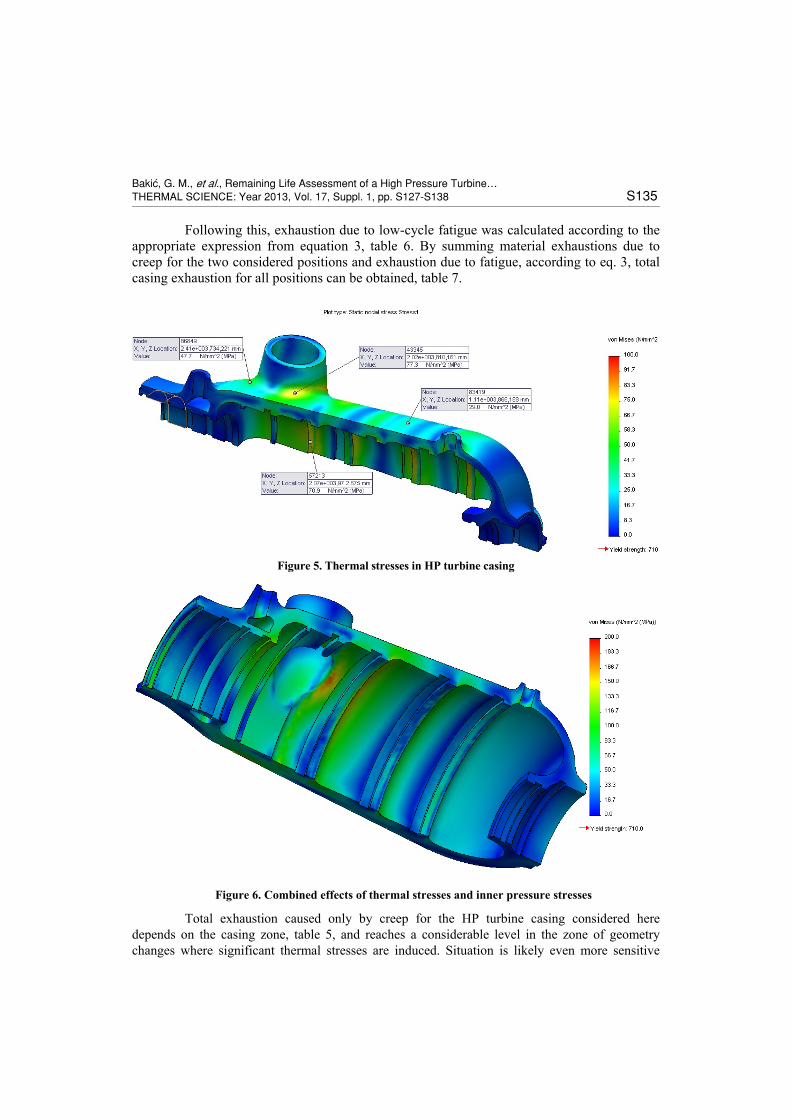
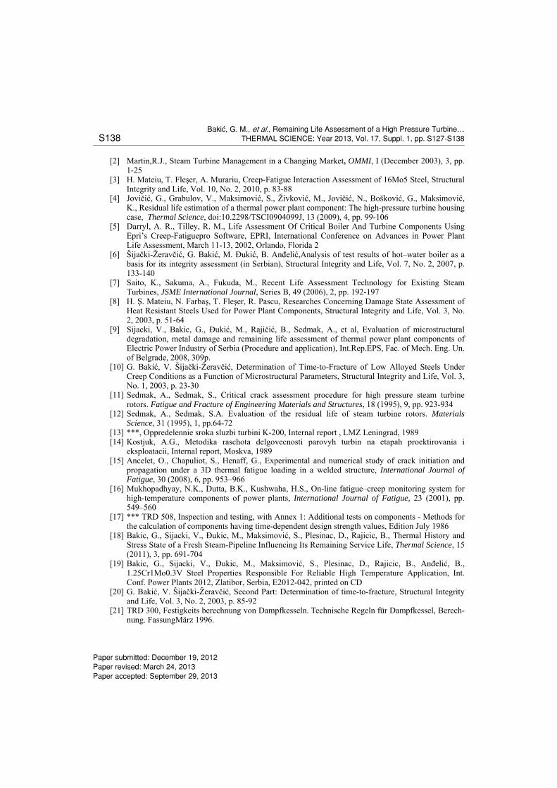
Unevenness of the temperature field and complex casing geometry lead to the occurrence of thermal stresses. Results of thermal stress analysis are shown in figure 5. Maximum stress gradients in the stationary heat conducting mode occur at locations with significant changes in geometry. Combined effect of stresses caused by inner pressure and temperature is shown in figure 6, from which it can be notices that maximum stresses occur in the nozzle zone, but also in the zone with changed geometry on the inner side (groove zone). These zones also represent locations of cracks revealed by NDT methods.
Calculation of exhaustion due to creep and fatigue
One of the necessary data for calculating exhaustion due to creep, eq. 2, is the time to fracture which is determined according to eq. 7. Considering that turbine casing metal was working at various temperatures, figure 2, times spent at specific temperatures are determined.
Effect of creep for steel cast 15H1M1FL below 510°C is negligible, hence the time spent on lower temperatures was added to this value. For every temperature from table 4, time to fracture was calculated based on the lower values of creep strengths for 100000 and 200000 h, figure 3, for static stresses caused by inner pressure and thermal stresses, figure 6. During the calculation of exhaustion, two positions on the inner surface of the casing were taken into consideration the location without stress concentration and the location of the groove. Results of total material exhaustion calculation for HP turbine casing caused by creep on the two selected locations are given in table 5. For calculating exhaustion caused by fatigue, eq. 1, it is necessary to determine the number of hot and cold starts that leads to fracture, i.e. the total amount of work resources for real operating parameters. The amount of resources spent during the previous service is estimated relative to above data. In order to determine the number of cycles until fracture, data about the amplitude stress for all types of cycles to fracture is necessary. Amplitude stresses are determined according to TRD norms series 300, for hot and cold starts until full service parameters are reached [21]. Amplitude stress determined for hot start is 626 MPa, and for cold start – 655 MPa. The number of cycles to fracture was determined from the diagram given in TRD norms [21, figure 8], 396 for hot start and 351 for cold start. Based on this data, the equivalent number of cycles was determined, eq. 2, for previously spent starts, along with the number of starts to fracture.
Table 4: Operating time in temperature intervals extrapolated for the total service life
T [C] do 510 510-520 520-530 530-540
Time [h] 43705 42621 63321 352
Table 5: Casing material exhaustion due to creep
Casing at the location without stress concentration 50Mpa Casing at the location of groove 80Mpa
T [C] do 510 520 530 540 do 510 520 530 540
tij[h] 43705 42621 63321 352 43705 42621 63321 352
ij[h] 3603792 1883831 608403 340816 541321 291907 151266 102575
tij/ij [%] 1.2 2.3 10.4 0.1 8.1 14.6 41.9 0.3
Ip [%] tij/ij = 14.0 tij/ij = 64.9
Baki}, G. M., et al., Remaining Life Assessment of a High Pressure Turbine… THERMAL SCIENCE: Year 2013, Vol. 17, Suppl. 1, pp. S127-S138 S135
Following this, exhaustion due to low-cycle fatigue was calculated according to the appropriate expression from equation 3, table 6. By summing material exhaustions due to creep for the two considered positions and exhaustion due to fatigue, according to eq. 3, total casing exhaustion for all positions can be obtained, table 7.
Figure 5. Thermal stresses in HP turbine casing
Figure 6. Combined effects of thermal stresses and inner pressure stresses
Total exhaustion caused only by creep for the HP turbine casing considered here depends on the casing zone, table 5, and reaches a considerable level in the zone of geometry changes where significant thermal stresses are induced. Situation is likely even more sensitive

Baki}, G. M., et al., Remaining Life Assessment of a High Pressure Turbine… S136 THERMAL SCIENCE: Year 2013, Vol. 17, Suppl. 1, pp. S127-S138
around the openings where the influence of thermal stresses is more significant, and where complete exhaustion in terms of creep occurs. Appearance of cracks around the opening zone can be explained only by the influence of creep and thermal stresses, however, appearance of cracks around the groove zone cannot. HP turbine casing exhaustion due to low-cycle fatigue, determined based on equivalent number of starts is very close to the total exhaustion value limit in terms of safety, but it is still insufficient for cracks to appear. Only the value of total exhaustion in grooves shows that exhaustion has exceeded 100%, which corresponds to NDT method analysis, since cracks were discovered in these zones. This suggests that cracks appeared due to simultaneous effects of creep and low-cycle fatigue. One of the factors that can increase the rate at which these cracks occur is the starting mode, i.e. deviation of prescribed heating rates given in table 2. In addition to the calculation of total exhaustion due to creep and fatigue, critical crack size, ac, was determined, eq. 4, along with data given in table 3 and it was 173.5 mm. Since ac is greater than the relevant wall thickness of 90 mm, table 1, the requirements for protection against brittle fracture have been fulfilled, hence there cannot be any bursting, only leakage in case of a penetrating crack. For this reason, it is recommended to check the rate at which detected cracks will propagate due to simultaneous effects of creep and fatigue.
Table 6: Material exhaustion due to fatigue Table 7: Material exhaustion due to creep and fatigue
Type of start
Number of hot starts
Number of cold starts
Equivalent number of
starts
nij[h] 378 101 261ij[h] 396 351 606
If [%] neq/Neq = 68.7
Exhaustion Ip, % If, %
Iu, %
Location without stress concentration 50MPa
14.0 68.7
82.7
Location of the groove 80MPa
64.9 134.6
Crack growth rate is checked for both cold and hot starts, eq. 5, as well as for influence of creep on crack growth, equation 6, for starting crack depth of 15 mm, based on data given in table 3. Values of in eq. 5 for hot and cold starts were determined using finite element method and were 240 MPa and 251 MPa, respectively. For crack growth prediction during the calendar year, it was assumed that the plant will have 3 hot and 3 cold starts and 6000 service hours in the usual mode. Results of crack growth rate calculations are given in table 8.
Table 8: Crack growth rate due to creep and fatigue
Crack growth rate per cycle or service hour
da/dnhot, mm/cycle da/dncold, mm/cycle da/d, mm/h
2.5210-2 2.9610-2 5.7410-5
Crack growth for an assumed period of 1 year, mm
ahot for 4 starts acold for 3 starts acreep za 6500h
0.10 0.09 0.37
a = ahot + acold + acreep = 0.56 mm/year
Crack growth rate due to combined effects of creep and low-cycle fatigue for maximum crack depth of 15 mm is relatively small. Generally, careful assessment and characterization of any casing cracks is critical. Therefore, during the outage, inspection of the most likely crack locations, including areas of prior cracking, can be used to assess any changes in relation to the previous inspection. The flows have occurred when a crack extends to a depth that does not support the pressure stresses. Because of relatively low rate of crack propagation due to simultaneous action of

Baki}, G. M., et al., Remaining Life Assessment of a High Pressure Turbine… THERMAL SCIENCE: Year 2013, Vol. 17, Suppl. 1, pp. S127-S138 S137
creep an low-cycle fatigue, and large critical crack length it is not necessary for existing crack depth to remove them from the safety point of view until next inspection period.
Conclusions
In this work results of the residual life assessment and critical flaw crack size of one high pressure steam turbine casing were presented. To solve the problem a geometrically numerical model of HP turbine casing was created. As results of the calculations, the stress states of casing for stationary and non-stationary working regime were obtained. The maximum stress areas overlap the zones on the casing where the cracks by NDT methods were detected. Residual life assessment of HP turbine casing was conducted taking into consideration the simultaneous influence of thermal fatigue and creep, and following conclusions can be formulated: The exhaustion of some casing zones only due to creep is different and it is very
noticeable in the zone of geometric changes and openings due to presence of significant thermal stresses.
However, crack appearance in the groove zones is the consequence of not just one damage mechanism but simultaneous action of low-cycle fatigue and creep. Namely, exhausting of material in the groove zones only due to creep or only due to low-cycle fatigue is lower than exhaustion limit and is insufficient for crack initiation, but exhaustion limit is overcome when both damage mechanisms act in the same time.
Critical flaw crack size (173.5mm), determined on the basis of the stresses, flaw geometry and casing material fracture toughness, is larger than casing wall thickness (90mm) and therefore the brittle fracture cannot occur.
Rate of crack propagation in term of combined action of creep and low-cycle fatigue for the maximal crack depth of 15mm and assumed operation is relatively slow (0.56mm/year). Because of relatively low rate of crack propagation and large critical crack length it is not necessary to remove existing cracks from safety point of view until the next inspection period
Nomenclature nij – number of cycles at temperature i and stress jNij – number of cycles to failure at temperature i and stress j tij– service time at temperature i and stress j,[h] ij – time to failure during creep at temperature i and stress j,[h] Iu – total exhaustion,[%] Ic – exhaustion from creep,[%] If – exhaustion from fatigue,[%] K1c – represents fracture toughness (MPa∙m1/2); – operating stress, [MPa] ac – critical crack depth, [m] c – factor that depends on the shape of the crack da– crack size increment, [m] dn– single cycle
– stress increment, [MPa] Cf , mf– fatigue coeficients d– time spent at a specific temperature, [h] Cc, mc– creep coeficients
CR 530
105– creep strength at 530°C for 100000h, [MPa]
C
xR 530
102 5– creep strength at 530°C for 200000h,
[MPa] T– temperature increment, [C] dnhot – single hot cycle dncold – single cold cycle da – outer diameter, [mm] dan – nominal outer diameter, [mm]
References [1] Laguarda Rodrígez, J. J., Carril, J. C., Fernandez, A. R., Valero, R. R., Aspects Of Remnant Life
Assessment In Old Steam Turbines, Journal of Maritime Research, ISSN: 169 7-4840, SEECMAR, II (2005), 3, pp. 41-58
Baki}, G. M., et al., Remaining Life Assessment of a High Pressure Turbine… S138 THERMAL SCIENCE: Year 2013, Vol. 17, Suppl. 1, pp. S127-S138
[2] Martin,R.J., Steam Turbine Management in a Changing Market, OMMI, I (December 2003), 3, pp. 1-25
[3] H. Mateiu, T. Fleşer, A. Murariu, Creep-Fatigue Interaction Assessment оf 16Мo5 Steel, Structural Integrity and Life, Vol. 10, No. 2, 2010, p. 83-88
[4] Jovičić, G., Grabulov, V., Maksimović, S., Živković, M., Jovičić, N., Bošković, G., Maksimović, K., Residual life estimation of a thermal power plant component: The high-pressure turbine housing case, Thermal Science, doi:10.2298/TSCI0904099J, 13 (2009), 4, pp. 99-106
[5] Darryl, A. R., Tilley, R. M., Life Assessment Of Critical Boiler And Turbine Components Using Epri’s Creep-Fatiguepro Software, EPRI, International Conference on Advances in Power Plant Life Assessment, March 11-13, 2002, Orlando, Florida 2
[6] Šijački-Žeravčić, G. Bakić, M. Đukić, B. Anđelić,Analysis of test results of hot–water boiler as a basis for its integrity assessment (in Serbian), Structural Integrity and Life, Vol. 7, No. 2, 2007, p. 133-140
[7] Saito, K., Sakuma, A., Fukuda, M., Recent Life Assessment Technology for Existing Steam Turbines, JSME International Journal, Series B, 49 (2006), 2, pp. 192-197
[8] H. Ş. Mateiu, N. Farbaş, T. Fleşer, R. Pascu, Researches Concerning Damage State Assessment of Heat Resistant Steels Used for Power Plant Components, Structural Integrity and Life, Vol. 3, No. 2, 2003, p. 51-64
[9] Sijacki, V., Bakic, G., Đukić, M., Rajičić, B., Sedmak, A., et al, Evaluation of microstructural degradation, metal damage and remaining life assessment of thermal power plant components of Electric Power Industry of Serbia (Procedure and application), Int.Rep.EPS, Fac. of Mech. Eng. Un. of Belgrade, 2008, 309p.
[10] G. Bakić, V. Šijački-Žeravčić, Determination of Time-to-Fracture of Low Alloyed Steels Under Creep Conditions as a Function of Microstructural Parameters, Structural Integrity and Life, Vol. 3, No. 1, 2003, p. 23-30
[11] Sedmak, A., Sedmak, S., Critical crack assessment procedure for high pressure steam turbine rotors. Fatigue and Fracture of Engineering Materials and Structures, 18 (1995), 9, pp. 923-934
[12] Sedmak, A., Sedmak, S.A. Evaluation of the residual life of steam turbine rotors. Materials Science, 31 (1995), 1, pp.64-72
[13] ***, Oppredelennie sroka sluzbi turbini K-200, Internal report , LMZ Leningrad, 1989 [14] Kostjuk, A.G., Metodika raschota delgovecnosti parovyh turbin na etapah proektirovania i
eksploatacii, Internal report, Moskva, 1989 [15] Ancelet, O., Chapuliot, S., Henaff, G., Experimental and numerical study of crack initiation and
propagation under a 3D thermal fatigue loading in a welded structure, International Journal of Fatigue, 30 (2008), 6, pp. 953–966
[16] Mukhopadhyay, N.K., Dutta, B.K., Kushwaha, H.S., On-line fatigue–creep monitoring system for high-temperature components of power plants, International Journal of Fatigue, 23 (2001), pp. 549–560
[17] *** TRD 508, Inspection and testing, with Annex 1: Additional tests on components - Methods for the calculation of components having time-dependent design strength values, Edition July 1986
[18] Bakic, G., Sijacki, V., Đukic, M., Maksimović, S., Plesinac, D., Rajicic, B., Thermal History and Stress State of a Fresh Steam-Pipeline Influencing Its Remaining Service Life, Thermal Science, 15 (2011), 3, pp. 691-704
[19] Bakic, G., Sijacki, V., Đukic, M., Maksimović, S., Plesinac, D., Rajicic, B., Anđelić, B., 1.25Cr1Mo0.3V Steel Properties Responsible For Reliable High Temperature Application, Int. Conf. Power Plants 2012, Zlatibor, Serbia, E2012-042, printed on CD
[20] G. Bakić, V. Šijački-Žeravčić, Second Part: Determination of time-to-fracture, Structural Integrity and Life, Vol. 3, No. 2, 2003, p. 85-92
[21] TRD 300, Festigkeits berechnung von Dampfkesseln. Technische Regeln für Dampfkessel, Berech-nung. FassungMärz 1996.
Paper submitted: December 19, 2012 Paper revised: March 24, 2013 Paper accepted: September 29, 2013