RELOCATION OF A VEHICLE DISMANTLING YARD ... appropriate site via a HGV bulker. A new batch of...
58
PLANNING STATEMENT RELOCATION OF A VEHICLE DISMANTLING YARD BOTTOM FARM, DESBOROUGH AIRFIELD, STOKE ALBANY ROAD, DESBOROUGH, KETTERING, NN14 2SP FRANK BEALE VEHICLE DISMANTERS LTD October 2011 Version 1 Final
-
Upload
vuonghuong -
Category
Documents
-
view
213 -
download
1
Transcript of RELOCATION OF A VEHICLE DISMANTLING YARD ... appropriate site via a HGV bulker. A new batch of...

PLANNING STATEMENT
RELOCATION OF A VEHICLE DISMANTLING YARD
BOTTOM FARM, DESBOROUGH AIRFIELD, STOKE ALBANY ROAD, DESBOROUGH, KETTERING, NN14 2SP
FRANK BEALE VEHICLE DISMANTERS LTD October 2011 Version 1 Final

GP PLANNING LTD PLANNING STATEMENT
B014-01 Planning Statement / NM 07/10/11
CONTENTS 1 THE PROPOSED DEVELOPMENT ....................................................................................... 1
1.1 Introduction .................................................................................................................................. 1
1.2 The Application Site and Surrounding Context .............................................................................. 2
1.3 Proposed Development ................................................................................................................. 3
2 PLANNING HISTORY ........................................................................................................ 5
2.1 Introduction .................................................................................................................................. 5
2.2 Previous Planning Permissions ...................................................................................................... 5
2.3 Current Proposals .......................................................................................................................... 5
3 PLANNING POLICY ........................................................................................................... 6
3.1 Introduction .................................................................................................................................. 6
3.2 European Policy ............................................................................................................................. 6
3.3 National Policy ............................................................................................................................... 6
3.4 Regional Policy .............................................................................................................................. 8
3.5 Local Policy .................................................................................................................................... 8
3.6 Catchment Area ............................................................................................................................. 9
4 ENVIRONMENTAL CONSIDERATIONS ............................................................................ 12
4.1 Ecology and Archaeology ............................................................................................................ 12
4.2 Traffic and Transport .................................................................................................................. 12
4.3 Ground and Surface Water .......................................................................................................... 12
4.4 Contaminated Land ..................................................................................................................... 13
4.5 Visual Impact .............................................................................................................................. 14
4.6 General Amenity .......................................................................................................................... 14
5 CONCLUSION .................................................................................................................. 15
APPENDICES APPENDIX 1: Validation Checklist
APPENDIX 2: Permission KE/89/0131
APPENDIX 3: Permission KT/2007/0350
APPENDIX 4: Flood Risk Assessment and Drainage Scheme
APPENDIX 5: SRL.110.11 Topographical Survey
GP PLANNING LTD PLANNING STATEMENT
B014-01 Planning Statement / NM 1 07/10/11
1 THE PROPOSED DEVELOPMENT
1.1 Introduction
1.1.1 This application has been submitted by GP Planning Ltd on behalf of Frank Beale Vehicle Dismantlers Ltd, and seeks to gain planning permission for the relocation of the vehicle dismantling yard at Bottom Farm, Desborough Airfield, to an adjacent site (the application site).
1.1.2 The relocation of the vehicle dismantling operation is required as the applicant is to be evicted from the current site of operation. Therefore to continue the operation of the company, an appropriately authorised site needs to be found.
1.1.3 This application is accompanied by the following documents and drawings: B014-01 Planning Statement, B014-01 Design and Access Statement, GPP-FB-BF-11-01 Site Location Plan 1:25,000, GPP-FB-BF-11-01a Site Location Plan, GPP-FB-BF-11-02 Site Plan, GPP-FB-BF-11-03 Site Layout Plan, GPP-FB-BF-11-04 Elevations of Polluted Car Storage, B014-01 Photograph Panel A, B014-01 Photograph Panel B, GPP-FB-BF-11-05 Historic Map, GPP-FB-BF-11-06 Illustrative Catchment Area Plan, GPP-FB-BF-11-07 De-pollution building elevations, GPP-FB-BF-11-08 Elevations of Portakabin, SRL.110.11 Topographical Survey, Flood Risk Assessment;
1.1.4 The Northamptonshire validation checklist has been included in appendix 1.
Applicant Profile
1.1.5 The company has a long history of operation in the Kettering area. The vehicle dismantling operation originated within Kettering, but was relocated by the Borough Council in 1989 to the Bottom Farm site. The operation has since been conducted within the parameters set by the conditions of permission of KE/89/0131, and is detailed in appendix 2. It is now the intention of the company to continue an identical operation at the land adjacent to their current Bottom Farm Site. Legal Procedure
1.1.6 Legal procedure between the applicant and the landowners has resulted in the eviction of the applicant from the current site of operation. The trial which took place on the 2nd August 2011 set a mandatory date of cessation of operation and vacation of the current site by the 23rd November 2011, after which any operations conducted by the client at the site will be legally considered to be trespassing. Therefore, the 23rd November 2011 is to be treated as the formal end date for all vehicle dismantling operations on the site.

GP PLANNING LTD PLANNING STATEMENT
B014-01 Planning Statement / NM 2 07/10/11
1.2 The Application Site and Surrounding Context
The Site
1.2.1 The site that is the subject of this application is situated adjacent to the current operations undertaken by Frank Beale Vehicle Dismantlers Ltd. The 0.9 ha site is situated at the end of the access track leading to the current site at Bottom Farm, at Desborough Airfield. The site location plans referenced GPP/FB/BF/11/01 and GPP/FB/BF/11/01a identify the site location.
1.2.2 The site is currently rough made ground. Evidence exists of former use through the presence of building foundations in the vicinity of the site entrance. Historical maps show that the site was previously in use as a water treatment works. Additionally the site is over grown; none of the vegetation on site is considered to be of any special ecological interest.
1.2.3 The topography of the site drops from north to south towards Harpers Book that runs along the southern boundary. The boundary is defined by a 2.6m high security fencing and thick vegetation along the western and southern boundaries. The Surrounding Area
1.2.4 The application site is bordered to the east by agricultural grassland which is a part of the Rockingham Estate. Directly to the west of the site, the area of land is currently subject to a planning application relating to the establishment of a Mobile Home and Retirement Park, which has yet to be determined.
1.2.5 The Pastures Travellers Site is located approximately 300m to the north east. The relocation of the vehicle dismantling yard moves the operations further away from the pastures site.
1.2.6 Generally, the site is well contained in visual terms. The closest residential settlement to the site is the West Lodge area that is situated to the south of the site. Due to the topography of the site, and the natural tree and hedgerow screening along the eastern boundary the West Lodge settlement has very limited views onto the application site.
1.2.7 To the north of the site, at the junction of the access track with the public highway to the proposed site is the Fox Pallets site. The current operations consist of wooden pallet production and the unauthorised wood chipping and stockpiling of processed wood chip.
1.2.8 The following designated sites are in closest proximity to the site; Brampton and Stoke Wood, an ancient and semi natural woodland situated approximately
1Km to the west of the site. Bowd Lane Wood, an ancient and semi-natural woodland situated approximately 1Km to the
north of the site. Mill Mound, Scheduled Ancient Monument situated at approximately 1.2 Km to the east of the
site. The monument has yet to be formally reviewed by English Heritage. Rawhaw Wood, ancient and semi-natural woodland situated approximately 1.3 Km to the
east.

GP PLANNING LTD PLANNING STATEMENT
B014-01 Planning Statement / NM 3 07/10/11
1.3 Proposed Development
Current Operations
1.3.1 It is proposed that the site operations will be of a largely identical nature to those that are currently being undertaken at the current Bottom Farm site. Currently, scrap vehicles, mainly consisting of cars and vans are brought into the site for dismantling. Once delivered to the site, the vehicles are depolluted, through the removal of any fuel, oils, lubricants, batteries and other potential pollutants within the confines of the de-pollution building. The cars are stored and stacked two high in regimental lines, with approximately 1 m gap around the stacks in order to allow ease of access to each vehicle stack. The site operation works on a self-service basis, whereby customers remove the required vehicle components themselves.
1.3.2 Once it is deemed to be necessary by the site operator, usually once a month, a mobile vehicle crusher is brought to site for the compaction of the vehicles, and subsequent removal offsite to an appropriate site via a HGV bulker. A new batch of vehicles is then brought onto site for dismantling.
1.3.3 As well as the second hand car part retail operation that is conducted at the site, the operator also runs a tyre changing service.
Proposed Development
1.3.4 A designated de-pollution building will be installed on site. The portable domed building will be 14 meters in length by 12 m in width and will be 5.5 m high at its highest point. The de-pollution building will contain appropriate drainage facilities, via the installation of a sump. Once full the sump will be drained, and its content removed off site for disposal at an appropriate facility via a tanker. Elevations of the de-pollution unit are shown in GPP-FB-BF-11-07.
1.3.5 To ensure that all potential contaminants are contained within an appropriate facility, a bunded fuel and chemical store will be provided on site. This will ensure that any spillages of potential pollutants will be contained.
1.3.6 Additionally, a designated polluted vehicle area will be defined at the site entrance. The area will be covered via a profiled sheet roof and enclosed on the western side by further profile sheet cladding to mitigate against the effects of prevailing weather conditions. The structure minimises the risk of contamination of the surrounding environment as rainfall will be diverted from the polluted vehicles, and the clean run-off contained within the site drainage system.
1.3.7 Additionally, the polluted vehicle area will be served by a drainage sump that will isolate any polluted liquid prior to its removal offsite. The building will be 3.5m high and will have a floor plan of 7.5m wide by 13m in length.
1.3.8 The site office will be situated at the entrance to the dismantling yard to allow for the regulation of the site security and customer movements. The dimensions of the office building portacabin will be 5m by 3m by 2.5m high, elevations of the portacabin unit are shown in GPP-FB-BF-11-07. In front of the dismantling yard entrance customer parking will be provided, as shown on drawing GPP-FB-BF-11-03 Site Layout Plan.

GP PLANNING LTD PLANNING STATEMENT
B014-01 Planning Statement / NM 4 07/10/11
1.3.9 The site will accept up to 1500 cars per annum for dismantling, and reclamation of parts for resale. The development will operate between 08:00 and 18:00 daily, 7 days a week, and will employ 3 members of staff. Vehicle breaking operations will be undertaken inline with the conditions of the permission at Bottom Farm. Condition 8 of permission KE/89/0131 states;
‘The car breaking activities hereby permitted shall take place solely between the hours of 8:00am to 6:00pm. Monday to Friday; 8:00am to 1:00pm Saturday and no other time whatsoever. The retailing activities hereby permitted shall take place solely between the hours of 8:00am to 6:00pm Monday to Sundays.’
1.3.10 The equipment to be used on site will consist of a 360 excavator fitted with an hydraulic grab to
manoeuvre the cars around the site, along with a forklift truck. The equipment is currently in use on the current site, and will be transferred to the application site once it is operational. Photos of the mobile plant to be used at the site are attached in Photograph Panel B.
1.3.11 Due to the desired operating hours at the site, there will be some need for lighting particularly in order to allow full working practices during the winter months. As such details of the external lighting scheme shall be submitted following the granting of planning permission.
1.3.12 The planning application seeks to regularise the steel security fence and gates that have been constructed around the application site. The fence is approximately 2.6m high and is set 1m in from the site boundary.
1.3.13 In order for the site to drain to an appropriate drainage system the development seeks permission to construct a water attenuation pond in the south east corner of the site. The pond will be of an appropriate size to deal with the runoff from the site. Its dimensions are 36m in length by 15.5m in width and has a volume of 495m3. Further information regarding the attenuation pond is contained in appendix 4.

GP PLANNING LTD PLANNING STATEMENT
B014-01 Planning Statement / NM 5 07/10/11
2 PLANNING HISTORY
2.1 Introduction
2.1.1 The site has an historical use as a Water Treatment Facility. Whilst no exact dates are provided with respect to the cessation of that use, the historical map from 1972 that accompanies this application indicates the previous use at the site; GPP/FB/BF/11/05 Historic Map. Since the cessation of the water treatment processes, the site has been subject to a number of planning applications and a permission. They are detailed in the following section.
2.2 Previous Planning Permissions
2.2.1 Two planning applications were submitted in 2006, ref KET/2006/0578 and KET/2006/0899, with respect to the authorisation of the land for processing, sorting, storage and sale of reclaimed building materials and architectural salvage. The applications were never determined as they were returned invalid and withdrawn, respectively.
2.2.2 In 2008 planning permission KET/2007/0350 was granted at the site. The permission authorised the erection of an office and a storage building and use of land as a builders yard. A former building that stood at the northern end of the site was demolished in compliance with the requirement of the planning permission.
2.2.3 The single story L shaped office and warehouse building has a footprint of 118m2. The building is 16 meters in length with a return of 10 meters, and 4.6 meters to the ridge. In addition to the building the permission allowed for the use of the land for a storage area and a builders yard. The boundary was to be fenced in the northern section with a 2.6m security fence along with a 2m fence and hawthorn fence around the storage area.
2.2.4 A copy of the permission documentation is included in appendix 3 of this planning statement.
2.3 Current Proposals
2.3.1 Various aspects of the permission were implemented by the landowner. Under the requirements of condition 3 of permission KET/2007/0350 the existing building situated in the northern section of the site was demolished, and a 2.6m security fence was erected around the site. As the permission only authorised a 2.6m fence around a section of the site, the current planning application needs to gain authorisation for the currently erected site fencing.
2.3.2 Generally, there is a defined difference between the use authorised by permission KET/2007/0350 and the proposed use as a vehicle dismantling yard and associated operations. However, there are similarities between aspects of the permission and proposed development. The storage use that was permitted by KET/2007/0350 will be largely utilised by the proposed application, with respect to the storage of the de-polluted vehicles. Additionally, the development will extend the permitted parking facilities north wards in order to allow for sufficient parking space for customers.

GP PLANNING LTD PLANNING STATEMENT
B014-01 Planning Statement / NM 6 07/10/11
3 PLANNING POLICY
3.1 Introduction
3.1.1 The relevant planning policies with respect to the proposed development are set out within this chapter.
3.2 European Policy
Directive 2000/53/EC, End of Life Vehicle; 2000
3.2.1 The overarching European Policy relating to the control of scrap cars is the directive relating to end of life vehicles. The directive requires that all,
Member States should take measures to ensure that economic operators set up systems for the collection, treatment and recovery of end-of life vehicles.
3.2.2 And that;
This Directive should cover vehicles and end-of life vehicles, including their components and materials, as well as spare and replacement parts, without prejudice to safety standards, air emissions and noise control.
3.2.3 Comment: The application allows for the treatment of end of life vehicles on a local scale. The application will provide the evidence that the operations that are to be undertaken at the application site will occur without prejudice to air emissions and noise control.
3.3 National Policy
Government Review of Waste Policy in England 2011
3.3.1 The Waste Review 2011 builds upon the waste hierarchy which was the core of the 2007 Waste Strategy for England. The key themes that are discussed within the review are; The need to focus on preventing waste as a priority, as a key component of
broader resource efficiency; The importance of treating waste as a resource and embedding waste policies into
a wider resource and material security policy; The need to remove barriers which prevent greater integration of household and
business waste policy and service delivery; The importance of policies which continue to promote high levels of high quality
recycling; and The need to continue to reduce the amount of waste going to landfill.
3.3.2 Comment: The development will allow for the reclamation of vehicle components for re-use,
and the de-pollution of vehicles before treatment at appropriate recycling facilities. This conforms with the requirement to divert waste away from landfill, as the site allows for the collection of scrap cars.

GP PLANNING LTD PLANNING STATEMENT
B014-01 Planning Statement / NM 7 07/10/11
Planning Policy Statements
3.3.3 Planning Policy Statements (PPS) contain national guidance on the interpretation and implementation of national strategies and government policy.
PPS1 Delivering Sustainable Development
3.3.4 This document sets out overarching planning policies for the delivery of sustainable development through the planning system. It states that sustainable development is the core principle underpinning planning.
3.3.5 Comment: The development will provide a facility for the handling of scrap vehicles and
ensure the continuation of an established operator within the Kettering area, thus allowing for the business to engage within the processes of sustainable economic growth; a requirement of PPS1.
PPS10 Planning for Sustainable Waste Management
3.3.6 PPS10 advises waste planning authorities “in deciding which sites to identify for waste
management facilities, waste planning authorities should (i) assess their suitability for development against each of the following criteria: - the extent to which they support the policies of this PPS; - the physical and environmental constraints on development, including existing and proposed
neighbouring land uses; - the cumulative effect of previous waste disposal facilities on the well-being of the local
community, including any significant adverse impacts on environmental quality, social cohesion or economic potential;
- the capacity of existing and potential transport infrastructure to support the sustainable movement of waste, and products arising from resource recovery, seeking when practicable and beneficial to use modes other than road transport.
(ii) give priority to the re-use of previously developed land and redundant agricultural and forestry buildings and their curtilages.
3.3.7 Comment: This document sets out overarching planning policies for the delivery of sustainable waste management through the planning system and is reflected in the Adopted Core Strategy for Waste in Northamptonshire. The site is situated on previously developed land and in the vicinity of the existing vehicle dismantling yard, where precedence for the same site operations have been set. As a result PPS10 gives priority to the use of these types of sites. There will be no adverse environmental impacts resulting from the development, demonstrated in chapter 4. Draft National Planning Policy Framework
3.3.8 In line with the fundamentals of the waste hierarchy in developing waste re-use and recovery
as a key compliance for waste treatment, the recently published Draft National Planning Policy Framework holds sustainable development principles at its core.
3.2.5 The Draft National Planning Policy Framework has been formulated as the guiding document that will shape the planning system in the future. The NPPF says at paragraph 7 of its introduction that it does not contain specific waste policies 'since national waste planning policy will be published alongside the National Waste Management Plan for England'. However, paragraph 7 goes on to say that local authorities should have regard to the policies in the

GP PLANNING LTD PLANNING STATEMENT
B014-01 Planning Statement / NM 8 07/10/11
Framework in preparing their waste plans. While the NPPF does not include any express policies in relation to waste development, the general principles of the Framework should nevertheless be taken into account in the determination of applications.
3.2.6 The Courts have long recognised that draft policy guidance issued by the Government is capable of being a material consideration in the determination of planning appeals. In this case, the draft NPPF is clearly a material consideration in that it signals a new approach to the determination of planning applications and planning appeals and, in particular, a strong presumption in favour of sustainable development. 3.2.7 Paragraph 14 of the NPPF says that:
'At the heart of the planning system is a presumption in favour of sustainable development, which should be seen as a golden thread running through both plan making and decision taking. Local planning authorities should plan positively for new development, and approve all individual proposals wherever possible ... All of these policies should apply unless the adverse impacts of allowing development would significantly and demonstrably outweigh the benefits, when assessed against the policies in this Framework taken as a whole'.
3.3.9 The operation to be undertaken at the site has sustainable practices at its core. The ability to
divert waste in the form of scrap vehicles away from landfill is a key example of this. Further to the diversion of waste, the components utilised from the site help to maintain operational vehicles, and is thus considered to be a recycling practice.
3.4 Regional Policy
3.4.1 Regional Spatial Strategies set out the strategic level planning policy for the regions. In 2010 the UK Government abolished the strategies under s79(6) of the Local Democracy Economic Development and Construction Act 2009. In the Autumn of 2010 the High Court rules that the Secretary of State’s decision to revoke Regional Spatial Strategies was unlawful as it had been taken without primary legislation. A statement was then issued by the Government reiterating their intention to remove Regional Spatial Strategies through the Localism Bill, and that this should be treated as a material consideration for planning applications. Despite a further legal challenge, it was confirmed that the Government’s intention to abolish Regional Spatial Strategies is a material consideration which should be taken into account when determining a planning application. A Commons Select Committee Report was published in Spring 2011 acknowledging the presence of a planning policy vacuum as a result.
3.5 Local Policy
3.5.1 The most relevant policies of the Northamptonshire Waste Core Strategy of the Local Development Framework Adopted 2010 are:
3.5.2 Policy CS1: Northamptonshire’s waste management capacity
This provision will come from a mix of extensions to existing sites, intensification or re-development of existing sites and new sites, providing they all meet the spatial strategy for waste management and are assessed as meeting environmental, amenity and other

GP PLANNING LTD PLANNING STATEMENT
B014-01 Planning Statement / NM 9 07/10/11
requirements. Allocations that will contribute to meeting provision will be identified in the Locations for Waste Development DPD.
3.5.3 Comment: The development will allow for the acceptance of up to 1500 vehicles per annum. The operation allows for the reuse of car components that are salvaged prior to their compaction and subsequent recycling of the baled vehicles at an appropriate site. The operation has been developed over time, and the relocation of the operation will allow for its continuation within the Kettering area. The re-use of components potentially prolongs the life of roadworthy vehicles, and provides a facility for the re-use of components prior to recycling.
3.5.4 Policy CS2: Spatial strategy for waste management Northamptonshire’s waste management network, particularly advanced treatment facilities with a sub-regional or wider catchment, will be focused within the central spine, and the sub-regional centre of Daventry. Development should be concentrated in Northampton, Wellingborough, Kettering, Corby and Daventry. Development in the smaller towns should be consistent with their local service role. Facilities in urban areas should be co-located together and with complementary activities.
3.5.5 Comment: The current operation has been developed to service the needs of the Kettering area with respect to the dismantling of scrap vehicles. Kettering and North Northamptonshire
3.5.6 Within the Adopted Core Spatial Strategy for North Northamptonshire, only Policy 11 on
the Distribution of Jobs is relevant. Whilst the relocation to the proposed site will not create an increase in jobs in the area, the authorisation of the site will allow for the continuation of the current operation along with the maintenance of the 3 jobs in the local area.
3.5.7 The land is currently situated on brownfield land, in close proximity to the Bottom Farm vehicle dismantling operation, which sets the precedence for the vehicle dismantling use in the area. The relevant saved local policy is stated within the Kettering Local Plan 2008, of which policy 7 deals with the protection of the open countryside. Whilst the proposed development sits within the countryside, the site is relatively self-contained due to the physical characteristics of the site and its surroundings.
3.5.8 As described above the development will be undertaken on the former water treatment works. Precedence has already been set in Northamptonshire with respect to the development of waste facilities on former water treatment facilities. Examples are; The Viridor, Waste Transfer Station and Materials Recycling Facility at Earls Barton and also the Waste Transfer Station at the Blisworth, operated by JS Tipper Hire. Evidence of the former use of the site as a water treatment facility is contained in Drawing GPP/FB/BF/11/05 Historic Map.
3.6 Catchment Area
3.6.1 The development is subject to the policy contained within the Control and Management of Development, Development Plan Document adopted in June 2011. Specific policy within the DPD dictates the need to identify the likely catchment area of waste sources for specific waste facilities. The proposed development is considered to be a waste use due to the acceptance of end of life vehicles.
GP PLANNING LTD PLANNING STATEMENT
B014-01 Planning Statement / NM 10 07/10/11
3.6.2 Paragraph 3.12 of the DPD sets out the definition of the scales of geographic influence that a waste facility may command. The facility at the application site is required to service the current area, and as such is considered on interpretation of policy to be a local scale facility, defined as;
Waste to be managed on site originates from within up to two adjacent local planning authority areas or an equivalent geographical area. The facility is intended to serve either an urban area and its immediate rural hinterland, or be located in a rural area for the purpose of dealing with agricultural and / or similar wastes produced locally. The facility should be for preliminary treatment, however in certain circumstances may be for advanced treatment. The facility supports the waste hierarchy and is not for the disposal of waste.
3.6.3 Development and Implementation Principles Supplementary Planning Document (SPD) which was adopted in September 2011 includes table SPD3 which indicates the proposed catchment area for facilities of differing scale. They are as follows;
3.6.4 The current operations serve an existing local market. Much of the vehicles delivered to the site
originate from the Desborough, Kettering, Corby, Northampton and Wellingborough area. Interpretation of the current site practices indicate that the development fits in with the definition of a local scale facility as defined in paragraph 3.12 of the CMD document. However, due to the nature of the business there are no defined collection routes due to the ad hoc nature of where the end of life vehicles originate.
3.6.5 As required by the Northamptonshire County Council’s Mineral and Waste Development Framework Development Plan Documents, an illustrative catchment area plan has been produced to indicate the geographical extent of the catchment area.
3.6.6 Rarely do waste operators dealing in end of life vehicles have outstanding contracts to collect regular sources of waste, which creates difficulty in defining specific boundaries from where waste is likely to arise from. However, Drawing GPP/FB/BF/11/06 Catchment Area Plan best represents the expected collection practices that will be undertaken at the application site once operational. It is important to note that these locations represent the current market that has been developed over a substantial period of time, and are crucial to the operation of the established vehicle dismantling operations. This situation has similarities with the example stated within paragraph 3.7 of the SPD which states,

GP PLANNING LTD PLANNING STATEMENT
B014-01 Planning Statement / NM 11 07/10/11
There may be some instances where a proposal could be demonstrated to (for example) have a regional catchment area even though the area extends beyond what would be considered to be ‘regional’. Specifically where the proposed facility will form part of an existing network.
3.6.7 The catchment area illustrated in drawing GPP/FB/BF/11/06 Catchment Area Plan covers an
area in the region of 1500 Km2. Whilst this is above the level stated for local scale facilities within table SPD3, it represents the existing commercial activities of the operation, and is significantly lower than the upper levels of the thresholds for sub-regional facilities.

GP PLANNING LTD PLANNING STATEMENT
B014-01 Planning Statement / NM 12 07/10/11
4 ENVIRONMENTAL CONSIDERATIONS
4.1 Ecology and Archaeology
4.1.1 The brownfield site is made up of rough ground which has been periodically disturbed due to former site operations and site clearance activities. There are no known sources of ecological interest at the site. Additionally, the site has no evidence of any ecological importance in terms of plants or fauna. Photograph Panel A provides a visual indication of the site condition with respect to the potential for ecological interest.
4.1.2 Due to the nature of the previous use on the site it is not proposed that there is any source of archaeological interest.
4.2 Traffic and Transport
4.2.1 The application site will be served by the existing access arrangements that are currently used by the vehicle dismantling operations at Bottom Farm.
4.2.2 The associated traffic movements at the site will be in line with the current operations at the Bottom Farm. The site is currently visited by up to 200 customers per week. Vehicles are brought to site on an ad hoc basis. Up to 1500 vehicles are delivered to the site per annum. A vehicle compaction unit is brought to site when deemed to be necessary by the site manager. Indications from current practices show that this figure averages at 15 loads out over a 3 month period.
4.2.3 It is proposed that the current customer base will be carried over to the new site, as such the traffic movements relating to the relocation of the vehicle dismantling yard will occur in line with the current traffic movements at Bottom Farm.
4.3 Ground and Surface Water
Ground and Surface water
4.3.1 The site is located in Flood Zone 1 and a Flood Risk Assessment is attached in appendix 4. The application site is not situated above an aquifer. This aspect of the development is covered by the Flood Risk Assessment. Site Drainage
4.3.2 The site will be laid to drain to the south east corner, where the water attenuation pond will be situated. The site will drain from the attenuation pond to Harpers Brook as current. Before draining to Harpers Brook the water will pass through a class 1 petrol interceptor to ensure that all water drained to the brook is clean.
4.3.3 The polluted vehicle storage area will be serviced by a sump, via a drain at the centre of the concreted pad. The potentially contaminated water will be separated from the rest of the site by a bund constructed around the pad. The sump that will be located below the concrete pad and will be emptied periodically.
GP PLANNING LTD PLANNING STATEMENT
B014-01 Planning Statement / NM 13 07/10/11
4.4 Contaminated Land
4.4.1 The nature of the past use of the site as a water treatment plant will require some remediation measurements at the site. Due to the likely levels of contamination and the timescale in which application is to be determined within, due to the eviction processes that are underway at the applicant’s current site of operation, it is proposed that appropriate conditions are added to the planning permission to ensure that ground contamination investigations are undertaken at the site.
4.4.2 Appropriate conditions may be words as follows;
‘Prior to the commencement of development the following components of a scheme dealing with the risks associated with contamination of the site shall each be submitted to and approved, in writing, by the Waste Planning Authority: 1. A preliminary risk assessment which has identified : All previous uses Potential contaminants with those uses A conceptual model of the site indicating sources, pathways and receptors Potentially unacceptable risks arising from contamination at the site
2. A site investigation scheme, based on (1) to provide information for a detailed
assessment of risk to all receptors that may be affected, including those offsite.
3. The site investigations results and the detailed risk assessment (2) and based on these, an options appraisal and remediation strategy giving full details of the remediation measures required and how they are to be undertaken.
4. A verification plan providing details of the data that will be collected in order to
demonstrate that the works set out in (3) are complete and identifying ay requirements for longer-term monitoring of pollutant linkages, maintenances and arrangements for contingency action.’
4.4.3 And;
‘If during development, contamination not previously identified is found to be present at the site then no further development (unless otherwise agreed in writing with the waste planning authority) shall be carried out until the developer has submitted, and obtained written approval from the Waste Planning Authority for, an amendment to the remediation strategy detailing the how this unsuspected contamination shall be dealt with.
4.4.4 These conditions have been adapted from permission 10-0007-WAS which was granted for a
End of Life Vehicle operation and scrap yard at Arkwright Road, Corby. Whilst the previous use of the site that permission 10-0007-WAS relates to is not identical to the previous use of the application site, the measure stated the proposed conditions allow for the appropriate contamination investigations to be undertaken at the site prior to the construction of the runoff attenuation pond.

GP PLANNING LTD PLANNING STATEMENT
B014-01 Planning Statement / NM 14 07/10/11
4.5 Visual Impact
4.5.1 The proposed development will have little negative visual impacts on the surrounding environment. The topography of the site, its location within the bottom of a valley and the current vegetation surrounding the site largely shelters the site from potential receptors.
4.5.2 The building that has the most potential impact on the visual landscape is the de-pollution building. Standing at 5.5m high at its highest point the domed building will be taller than the site boundary fencing. As described in the above paragraph, much of the visual impact will be mitigated by the surrounding vegetation, particularly to the south of the site and the lines of sight from West Lodge.
4.5.3 The proposed depollution building is of a similar scale and massing to the office and storage building that was permitted at the site (KET/2007/0350). The permitted office and storage building was designed to stand 4.6m high to the ridge of the roof. The visual impact of the depollution building will be of a similar scale or less than what was considered to be appropriate for the office building due to the position of the depollution further down the sloping site. The topographical survey attached in appendix 5 shows the change in gradient at the proposal site and details of the permission KT/2007/0350 are attached in appendix 3.
4.6 General Amenity
Dust
4.6.1 The on-site operations will not be of an inherently dusty nature. The provision of a concrete surface will reduce the risk of dust creation with respect to general movements and operations at the site. Additionally, de-pollution of cars will occur within the building, and dismantling of the vehicles occurs on an ad hoc basis. Noise
4.6.2 The noise levels will be in line with the current activities at the existing site, due to the transfer of operations. Condition 7 of permission KE/89/0131 deals with acceptable noise mitigation strategy and states the following;
‘No panel beating, hammering or other noisy operations shall be carried out other than between the hours of 0800 and 1800 on weekdays, 0800 and 1300 on Saturdays and at no time on Sunday or Bank Holidays’
4.6.3 The operations will occur in line with the stipulations of the extant planning permission at Bottom Farm. Odour, Litter and Vermin
4.6.4 The development will not have an undue effect on the surrounding environment with respect to issues surrounding Odour, Litter and Vermin. The nature of the vehicles dismantled at the site, and the onsite operations means that there is little potential for any issues surrounding odour, litter and vermin to arise.

GP PLANNING LTD PLANNING STATEMENT
B014-01 Planning Statement / NM 15 07/10/11
5 CONCLUSION
5.1.1 The proposed development will allow for the continuation of a previously established business in the Kettering area. The nature of the development conforms with national and local planning policy and particularly to strategic waste treatment goals.
5.1.2 The site operations will be undertaken on a brownfield site, in proximity to the previously used site. As such precedence has been established by the previous site in the locality and the site has the benefit of a recent permission for commercial development.
5.1.3 Chapter 4 of the planning statement has considered the potential effect of the development on the surrounding environment. Where deemed to be necessary appropriate technical assessments have been undertaken to minimise the impact of the development on its surroundings.

GP PLANNING LTD PLANNING STATEMENT
B014-01 Planning Statement / NM Appendix 07/10/11
APPENDIX 1: Validation Checklist
National Requirements Document / Plan
Additional Notes / Comment
Completed Application Form
Planning Portal reference: 01641522
Site location plan (1:1250 or 1:2500) showing direction of north
GPP/FB/BF/11/01 AND GPP/FB/BF/11/01a
Block plan of the site (1:100 or 1:200) showing any site boundaries i.e. red line Site Plan
GPP/FB/BF/11/02 Site Plan, GPP/FB/BF/11/03 Site Layout Plan
Existing and proposed elevations (1:50 or 1:100)
Depollution Building, Office and Storage building
Existing and proposed floor plans (1:50 or 1:100)
Depollution Building, Office and Storage building
Roof plan (1:50 or 1:100) Not necessary.
Existing and proposed site sections and finished floor and site levels (1:50 or 1:100)
Not necessary.
Ownership Certificates (A, B, C or D – as applicable)
Not necessary.
Agricultural Holdings Certificate
Not necessary
Design and Access Statement, if required
Included.
Appropriate fee Fee calculated on the basis of the site area £1530
Notice under Article 6 of the Town and Country Planning (General Development Procedure Order 1995 must be given and/or published, where Ownership Certificates B, C or D used
Not necessary.
GP PLANNING LTD PLANNING STATEMENT
B014-01 Planning Statement / NM Appendix 07/10/11
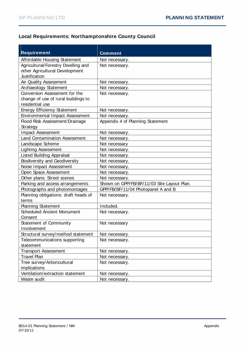
Local Requirements: Northamptonshire County Council
Requirement Comment
Affordable Housing Statement Not necessary. Agricultural/Forestry Dwelling and other Agricultural Development Justification
Not necessary.
Air Quality Assessment Not necessary. Archaeology Statement Not necessary. Conversion Assessment for the change of use of rural buildings to residential use
Not necessary.
Energy Efficiency Statement Not necessary. Environmental Impact Assessment Not necessary. Flood Risk Assessment/Drainage Strategy
Appendix 4 of Planning Statement
Impact Assessment Not necessary. Land Contamination Assessment Not necessary. Landscape Scheme Not necessary Lighting Assessment Not necessary. Listed Building Appraisal Not necessary. Biodiversity and Geodiversity Not necessary. Noise Impact Assessment Not necessary. Open Space Assessment Not necessary. Other plans: Street scenes Not necessary. Parking and access arrangements Shown on GPP/FB/BF/11/03 Site Layout Plan. Photographs and photomontages GPP/FB/BF/11/04 Photopanel A and B Planning obligations: draft heads of terms
Not necessary.
Planning Statement Included. Scheduled Ancient Monument Consent
Not necessary.
Statement of Community Involvement
Not necessary
Structural survey/method statement Not necessary. Telecommunications supporting statement
Not necessary.
Transport Assessment Not necessary. Travel Plan Not necessary. Tree survey/Arboricultural implications
Not necessary.
Ventilation/extraction statement Not necessary. Waste audit Not necessary.
GP PLANNING LTD PLANNING STATEMENT
B014-01 Planning Statement / NM Appendix 07/10/11
APPENDIX 2: Permission KE/89/0131


GP PLANNING LTD PLANNING STATEMENT
B014-01 Planning Statement / NM Appendix 07/10/11
APPENDIX 3: Permission KT/2007/0350

GP PLANNING LTD PLANNING STATEMENT
B014-01 Planning Statement / NM Appendix 07/10/11
APPENDIX 4: Flood Risk Assessment and Drainage Scheme

GP PLANNING LTD PLANNING STATEMENT
B014-01 Planning Statement / NM Appendix 07/10/11
APPENDIX 5: SRL.110.11 Topographical Survey

DESIGN AND ACCESS STATEMENT
RELOCATION OF A VEHICLE DISMANTLING YARD
BOTTOM FARM, DESBOROUGH AIRFIELD, STOKE ALBANY ROAD, DESBOROUGH, NN14 2SP
FRANK BEALE VEHICLE DISMANTLERS LTD October 2011 Version 1 Final

DESIGN AND ACCESS STATEMENT
B014-01 Design and Access Statement / NM 10/10/11
Design and Access
Introduction
This design and access statement forms part of the suite of planning application documents that have been submitted by GP Planning Ltd to Northamptonshire County Council. The documents have been submitted on behalf of Frank Beale Vehicle Dismantler Ltd, and relate to a planning application that seeks to gain permission for the relocation of a vehicle dismantling operation at Bottom Farm, Desborough Airfield, Stoke Albany Road, Besborough, Kettering, NN14 2SP. The Design and Access Statement accords with industry guidance, Design and Access Statements how to read, write and use them (CABE, 2007), and the requirements of Northamptonshire County Council, set out in the Northamptonshire County Councils Local List Requirements. The Design and Access Statement considers the following in relation to the proposed development:
Use of the Site Amount of Development Layout Scale Appearance Access
Use of the Site
The site is currently an area of vacant brownfield land, previously used as a water treatment facility. The application site will be used as a vehicle dismantling yard, whereby scrapped cars are depolluted and made available for component reclamation prior to their compaction and off site removal for recycling at an appropriate facility. It is proposed that the site will accept up to 1500 vehicles per annum for de-pollution and component reclamation. Amount of Development
The application seeks to gain permission for the relocation of the current operations of Frank Beale Vehicle Dismantlers Ltd to the adjacent site at Bottom Farm, and consequently seeks to gain authorisation for the transferral of all current operational process to the application site. The development will therefore consist of the following components;
Retrospective authorisation of boundary fencing and security gate; Formulisation of customer parking area at site entrance; Provision of hard surface in dismantling yard; and Construction of vehicle de-pollution unit, tyre storage bay, crushing bay, site office, and
bunded fuel and chemical store and wheel wash down.

DESIGN AND ACCESS STATEMENT
B014-01 Design and Access Statement / NM 10/10/11
Layout
The L shaped site is defined by two specific areas. The northern section of the site will be utilised as a customer parking facility. The fenced compound that sits next to the parking facility will be the designated vehicle dismantling yard. The dismantling yard will be further segregated by defined areas for accepting polluted cars, the de-pollution of the cars, component storage and de-polluted vehicle storage. The site layout is indicated diagrammatically by drawing GPP-FB-BF-11-03 Site Layout Plan. Scale
The scale of the components to be formalised and constructed on site are as follows; Bonundary fencing around the vicinity of vehicle dismantling compound, at a height of
approximately 2.6m; 1 x Site office at 5m in length by 3m wide and 2.5m high; 1 x De-pollution unit at 14m in length by 12m in width and 5.5m to its highest point; 1 x Crushing Bay which will be 13m long by 7.5m wide, and 2.5m high; 1 x Covered polluted car storage area, storage will occur on a concreted pad 13m in
length by 7.5m wide. The profiled sheet roof will stand at 3.5m high. 1 x Tyre Bay at 5m in length by 3.5m wide and 2.5m in height; and 1 x Bunded fuel and chemical store, dimensions are 14m by 10m. 1 x Drainage pond 36m in length by 15.5m in width with a storage capacity of 495m3.
Appearance
The development will be largely sheltered due to its location and the surrounding vegetation. The boundary fencing around the dismantling yard has been finished in a dark green colour, in order to allow for some blending of the site in to the surrounding environment, as shown in Photopanel A. The remainder of the fencing around the development site will consist of steel palisade security fencing. The de-pollution building will be the largest structure at the site, and will be defined by its curving roof. The structure will be finished in grey. The development will also consist of the construction of an office building and storage bays. The polluted car storage area will be covered by a profiled sheet panel roof. The roof will cover the full floor area of the identified area and will slope from south to north for drainage purposes. The western side of the canopy will be covered with profiled sheet panels to shelter the polluted vehicles from the effects of the prevailing weather systems. To prevent spillage of cars outside of the defined area the bottom of the unit will be enclosed by crash barriers. The structure will be finished in grey. It is proposed that there will be little impact by the stockpiling of the cars on the appearance of the facility as the stockpiles will be limited to two high; thus remaining below the height of the boundary fencing.

DESIGN AND ACCESS STATEMENT
B014-01 Design and Access Statement / NM 10/10/11
Access
The development will utilise the existing access arrangements at Bottom Farm. Due to the proximity to the current operations, the proposed site will utilise the access onto the public highway. Access from the public highway to the site will be gained via the current access road used by the current vehicle dismantling operations. The access arrangements are shown in Photopanel A.

Flood Risk Assessment
BCALCONSULTING. Orient House, Church Way, Wellingborough, Northamptonshire, NN8 4HJ Telephone: 01933 440024 Fax: 01933 440041 E-mail: [email protected] Web: www.bcal.co.uk
Proposed End of Life Vehicle Yard
Road to Pastures Caravan Site Desborough
For
Mr F Beale
Report Reference: 4668R001A FRA
Date: September 2011 Revision A: October 2011

4668 R001A Flood Risk Assessment Proposed ELV Yard, Desborough October 2011
O:projects\4600\4668\Admin\4668R001FRA\4668R001AFRA.pdf
REVISION RECORD Report Ref: 4668R001A FRA Rev Description Date Originator Checked
- Planning Issue 14/09/2011 MA PK A Site Layout Plan (Appendix B)
revised. 07/10/2011 MA PK
Note. Revisions to text are marked by a vertical line in the right hand column of the revised paragraph.
Disclaimers This report has been prepared for the sole use of the named client and, consequently, is confidential to the client and his professional advisors. The Contracts (Rights of Third Parties) Act 1999 does not apply, nothing in this report confers or purports to confer on any third party any benefit or right. No responsibility whatsoever is accepted to any other person than the named client and, consequently, the contents of this report should not be relied upon by third parties for the whole or any part of its contents. This report is made on behalf of BCAL, no individual is personally liable, and by receiving this report and acting upon it, the client - or any third party relying on it - accepts that no individual is personally liable in contract, tort, or breach of statutory duty (including negligence). This report is a risk-based assessment based on data currently available at the time of preparation. If the available data is found to be inaccurate or incomplete, the results could differ. BCAL accepts no liability should this prove to be the case. The information presented and conclusions drawn are for guidance purposes only and offer no guarantee to the accuracy of the predicted water levels described.
1

4668 R001A Flood Risk Assessment Proposed ELV Yard, Desborough October 2011
O:projects\4600\4668\Admin\4668R001FRA\4668R001AFRA.pdf
Contents Page Page No.
4668R001A FRA Contents Page 2 1.0 Introduction 3 2.0 Site Description and Proposed Redevelopment 3 3.0 Definition of Flood Hazard 4 4.0 Probability 5 5.0 Surface Water Management Measures 5 6.0 Foul Water Management Measures 6 7.0 Management of Residual Risks 6 8.0 Conclusion 7 Appendices Appendix A Location Plan BCAL drawing no. 4668-01 Appendix B Site Layout Plan ECP&L drawing no. GPP/FB/BF/11/03 rev 2 Appendix C Environment Agency Indicative Flood Map Appendix D PPS Tables D1 and D2 Appendix E Greenfield Runoff Calculation Appendix F Storm Water Storage Calculation Appendix G Indicative Surface Water Attenuation BCAL drawing no. 4668-02
2

4668 R001A Flood Risk Assessment Proposed ELV Yard, Desborough October 2011
O:projects\4600\4668\Admin\4668R001FRA\4668R001AFRA.pdf
1.0 Introduction 1.1 This report comprises a Flood Risk Assessment in support of a planning application for a
relocated End of Life Vehicle (ELV) at land located off the road to Pastures Caravan site Desborough. The site is currently unoccupied but has been used previously and has a site area of 0.89ha.
1.2 The objective of this report is to provide the Local Planning Authority (LPA) with
sufficient information on flooding and flood risk to enable these issues to be considered in the planning process. The report will consider the issues set out in Appendix E ‘The Assessment of Flood Risk’ set out in Planning Policy Statement 25: Development and Flood Risk (PPS 25).
2.0 Site Description and Proposed Redevelopment 2.1 Existing Site 2.1.1 The proposed redevelopment site is currently unoccupied, however, the site has been
utilised in the past as a sewage treatment works. The site has a total site area of 0.89ha is located at co-ordinates 481072, 285388 as shown on the location plan enclosed in Appendix A.
2.1.2 Harpers Brook is located adjacent to the southern boundary of the site. Harpers Brook
is classified as an ordinary watercourse in this location. 2.2 Proposed Redevelopment 2.2.1 It is proposed to construct an ELV yard on the site which will have an impermeable area
of 0.68ha (6800m2). The proposed redevelopment is shown in Appendix B. 2.3 Geology of the Area 2.3.1 From inspection of the geological maps for the site it would appear that the site is
underlain by Till which is overlaying Whitby Mudstone. It is therefore unlikely that the soils characteristics will be suitable for use with infiltration techniques.
2.4 Vulnerability Classification 2.4.1 The site is to be used for a ELV yard and is classified as Less Vulnerable within PPS 25
table D2. An extract of table D2 is enclosed in Appendix D.
3
4668 R001A Flood Risk Assessment Proposed ELV Yard, Desborough October 2011
O:projects\4600\4668\Admin\4668R001FRA\4668R001AFRA.pdf
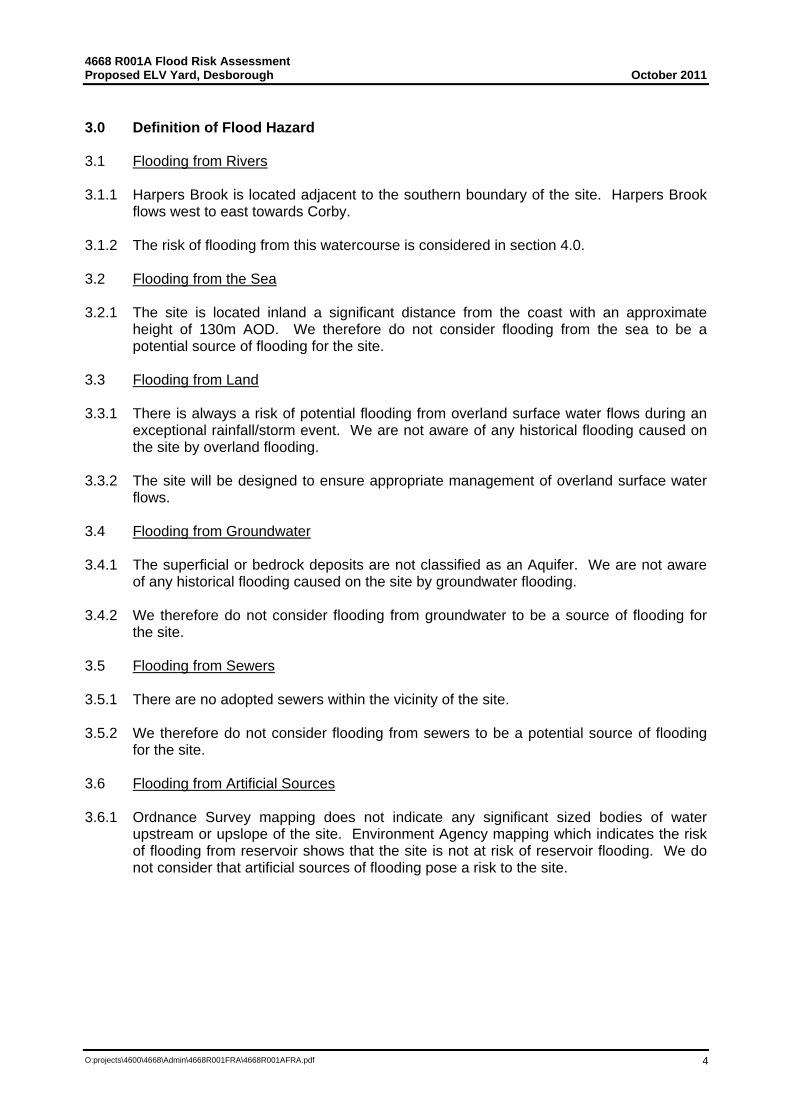
3.0 Definition of Flood Hazard
3.1 Flooding from Rivers 3.1.1 Harpers Brook is located adjacent to the southern boundary of the site. Harpers Brook
flows west to east towards Corby. 3.1.2 The risk of flooding from this watercourse is considered in section 4.0. 3.2 Flooding from the Sea 3.2.1 The site is located inland a significant distance from the coast with an approximate
height of 130m AOD. We therefore do not consider flooding from the sea to be a potential source of flooding for the site.
3.3 Flooding from Land 3.3.1 There is always a risk of potential flooding from overland surface water flows during an
exceptional rainfall/storm event. We are not aware of any historical flooding caused on the site by overland flooding.
3.3.2 The site will be designed to ensure appropriate management of overland surface water
flows. 3.4 Flooding from Groundwater 3.4.1 The superficial or bedrock deposits are not classified as an Aquifer. We are not aware
of any historical flooding caused on the site by groundwater flooding. 3.4.2 We therefore do not consider flooding from groundwater to be a source of flooding for
the site. 3.5 Flooding from Sewers 3.5.1 There are no adopted sewers within the vicinity of the site. 3.5.2 We therefore do not consider flooding from sewers to be a potential source of flooding
for the site. 3.6 Flooding from Artificial Sources 3.6.1 Ordnance Survey mapping does not indicate any significant sized bodies of water
upstream or upslope of the site. Environment Agency mapping which indicates the risk of flooding from reservoir shows that the site is not at risk of reservoir flooding. We do not consider that artificial sources of flooding pose a risk to the site.
4
4668 R001A Flood Risk Assessment Proposed ELV Yard, Desborough October 2011
O:projects\4600\4668\Admin\4668R001FRA\4668R001AFRA.pdf
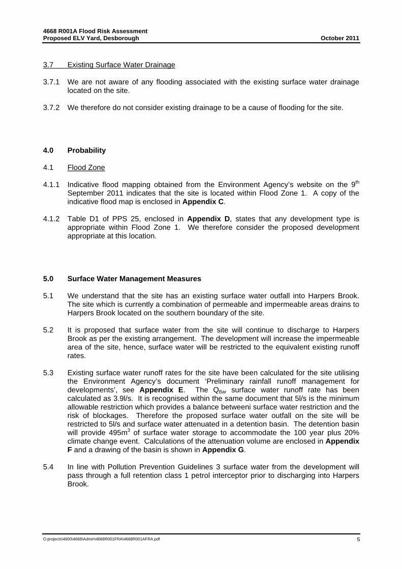
3.7 Existing Surface Water Drainage 3.7.1 We are not aware of any flooding associated with the existing surface water drainage
located on the site. 3.7.2 We therefore do not consider existing drainage to be a cause of flooding for the site. 4.0 Probability 4.1 Flood Zone 4.1.1 Indicative flood mapping obtained from the Environment Agency’s website on the 9th
September 2011 indicates that the site is located within Flood Zone 1. A copy of the indicative flood map is enclosed in Appendix C.
4.1.2 Table D1 of PPS 25, enclosed in Appendix D, states that any development type is
appropriate within Flood Zone 1. We therefore consider the proposed development appropriate at this location.
5.0 Surface Water Management Measures 5.1 We understand that the site has an existing surface water outfall into Harpers Brook.
The site which is currently a combination of permeable and impermeable areas drains to Harpers Brook located on the southern boundary of the site.
5.2 It is proposed that surface water from the site will continue to discharge to Harpers
Brook as per the existing arrangement. The development will increase the impermeable area of the site, hence, surface water will be restricted to the equivalent existing runoff rates.
5.3 Existing surface water runoff rates for the site have been calculated for the site utilising
the Environment Agency’s document ‘Preliminary rainfall runoff management for developments’, see Appendix E. The QBar surface water runoff rate has been calculated as 3.9l/s. It is recognised within the same document that 5l/s is the minimum allowable restriction which provides a balance betweeni surface water restriction and the risk of blockages. Therefore the proposed surface water outfall on the site will be restricted to 5l/s and surface water attenuated in a detention basin. The detention basin will provide 495m3 of surface water storage to accommodate the 100 year plus 20% climate change event. Calculations of the attenuation volume are enclosed in Appendix F and a drawing of the basin is shown in Appendix G.
5.4 In line with Pollution Prevention Guidelines 3 surface water from the development will
pass through a full retention class 1 petrol interceptor prior to discharging into Harpers Brook.
5

4668 R001A Flood Risk Assessment Proposed ELV Yard, Desborough October 2011
O:projects\4600\4668\Admin\4668R001FRA\4668R001AFRA.pdf
6.0 Foul Water Management Measures 6.1 There are no existing foul water sewers within close proximity of the development site. It
is therefore proposed that foul water will be held on site in an enclosed cesspool as it is on the present site.
6.2 Foul water will be limited there are only 4 employees proposed on the site. 7.0 Management of Residual Risks 7.1 There will always be a residual risk of overland flooding if the surface water drains are
not maintained sufficiently or during an exceptional storm event when the surface water drainage system is unable to cope with the rate or volume of rainfall. Normal maintenance will be required to the on and off site drainage systems. If flooding occurs due to lack of maintenance or during an exceptional storm event, the speed of inundation should be slow and should not endanger human life.
7.2 The development will complete a normal maintenance regime to ensure that on site
drainage is adequately maintained for the life time of the development. 7.3 As the proposed redevelopment will not displace flood water and the rate of surface
water runoff should not increase, the risk of flooding to downstream neighbours should not increase as a result of the proposed redevelopment.
7.4 The detailed level design of the buildings and surrounding ground levels should ensure
that there are lowered routes between the buildings to ensure surface water is not trapped or forced into the buildings.
6
4668 R001A Flood Risk Assessment Proposed ELV Yard, Desborough October 2011
O:projects\4600\4668\Admin\4668R001FRA\4668R001AFRA.pdf
8.0 Conclusions 8.1 It is proposed to construct a ELV yard on the site which is located at land of the road to
Pastures Caravan Site, Desborough. The site is currently unoccupied with a combination of permeable and impermeable areas. The proposed redevelopment will have an impermeable areas of 0.68ha (6800m2).
8.2 The site to be developed has no known history of flooding. 8.3 The site would appear to be in Flood Zone 1 as set out in PPS25 The proposed
development complies with the type of development permitted in PPS25, for Flood Zone 1.
8.4 Surface water runoff from the site will be restricted to 5l/s and attenuation provided for
the 1 in 100 year plus climate change event. The surface water outfall will comply with the requirements of Pollution Prevention Guidelines 3 and provide a full retention class 1 petrol interceptor.
9.5 As the proposed development will not displace flood water and the rate of surface water
runoff should not increase, the risk of flooding to downstream neighbours should not increase as a result of the proposed development.
9.6 There will always be a residual risk of overland flooding if the surface water drains are
not maintained and become blocked. The development will complete a normal maintenance regime to ensure that on site drainage is adequately maintained for the life time of the development.
7

4668 R001A Flood Risk Assessment Proposed ELV Yard, Desborough October 2011
O:projects\4600\4668\Admin\4668R001FRA\4668R001AFRA.pdf
Appendix A
Location Plan BCAL drawing no. 4668-01
8

SITE LOCATION
9

4668 R001A Flood Risk Assessment Proposed ELV Yard, Desborough October 2011
O:projects\4600\4668\Admin\4668R001FRA\4668R001AFRA.pdf
Appendix B
Site Layout Plan ECP&L drawing no. GPP/FB/BF/11/03 rev 2
10

11

4668 R001A Flood Risk Assessment Proposed ELV Yard, Desborough October 2011
O:projects\4600\4668\Admin\4668R001FRA\4668R001AFRA.pdf
Appendix C
Environment Agency Indicative Flood Map
Environment Agency Indicative Flood Mapping – 23rd September 2011
12

4668 R001A Flood Risk Assessment Proposed ELV Yard, Desborough October 2011
O:projects\4600\4668\Admin\4668R001FRA\4668R001AFRA.pdf
Appendix D
PPS 25 Table D1 and D2
13

4668 R001A Flood Risk Assessment Proposed ELV Yard, Desborough October 2011
O:projects\4600\4668\Admin\4668R001FRA\4668R001AFRA.pdf
Appendix E
Greenfield Runoff Calculation
14
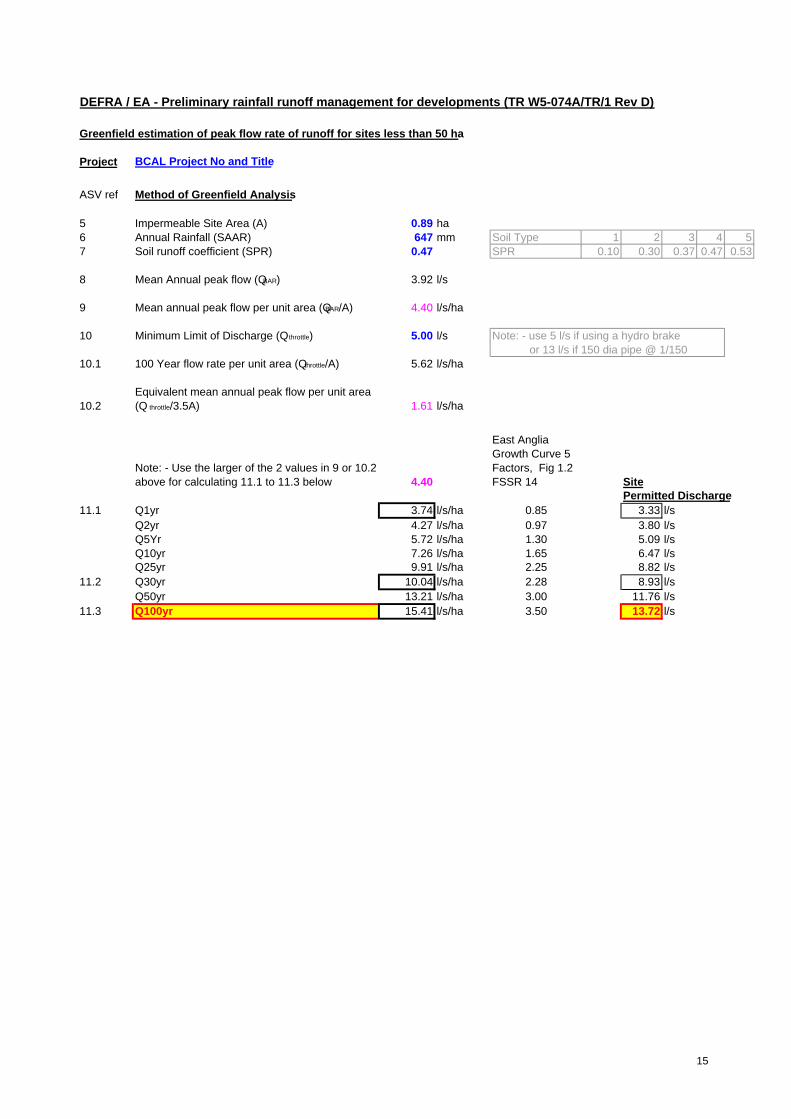
DEFRA / EA - Preliminary rainfall runoff management for developments (TR W5-074A/TR/1 Rev D)
Greenfield estimation of peak flow rate of runoff for sites less than 50 ha
Project
ASV ref Method of Greenfield Analysis
5 Impermeable Site Area (A) 0.89 ha6 Annual Rainfall (SAAR) 647 mm Soil Type 1 2 3 4 57 Soil runoff coefficient (SPR) 0.47 SPR 0.10 0.30 0.37 0.47 0.53
8 Mean Annual peak flow (QBAR) 3.92 l/s
9 Mean annual peak flow per unit area (QBAR/A) 4.40 l/s/ha
10 Minimum Limit of Discharge (Q throttle) 5.00 l/s Note: - use 5 l/s if using a hydro brake or 13 l/s if 150 dia pipe @ 1/150
10.1 100 Year flow rate per unit area (Q throttle/A) 5.62 l/s/ha
10.2Equivalent mean annual peak flow per unit area (Q throttle/3.5A) 1.61 l/s/ha
Note: - Use the larger of the 2 values in 9 or 10.2 above for calculating 11.1 to 11.3 below 4.40
East Anglia Growth Curve 5 Factors, Fig 1.2 FSSR 14 Site
Permitted Discharge11.1 Q1yr 3.74 l/s/ha 0.85 3.33 l/s
Q2yr 4.27 l/s/ha 0.97 3.80 l/sQ5Yr 5.72 l/s/ha 1.30 5.09 l/sQ10yr 7.26 l/s/ha 1.65 6.47 l/sQ25yr 9.91 l/s/ha 2.25 8.82 l/s
11.2 Q30yr 10.04 l/s/ha 2.28 8.93 l/sQ50yr 13.21 l/s/ha 3.00 11.76 l/s
11.3 Q100yr 15.41 l/s/ha 3.50 13.72 l/s
BCAL Project No and Title
15

4668 R001A Flood Risk Assessment Proposed ELV Yard, Desborough October 2011
O:projects\4600\4668\Admin\4668R001FRA\4668R001AFRA.pdf
Appendix F
Storm Water Storage Calculation
16

Summary of Results for 100 year Return Period
StormEvent
MaxLevel(m)
MaxDepth(m)
MaxControl(l/s)
MaxVolume(m³)
Status
15 min Summer 128.880 0.855 3.8 193.3 O K30 min Summer 128.994 0.969 4.1 225.0 O K60 min Summer 129.112 1.087 4.3 259.7 O K120 min Summer 129.228 1.203 4.6 295.4 O K180 min Summer 129.288 1.263 4.7 314.7 O K240 min Summer 129.325 1.300 4.7 326.5 O K360 min Summer 129.360 1.335 4.8 338.3 O K480 min Summer 129.370 1.345 4.8 341.5 O K600 min Summer 129.368 1.343 4.8 341.0 O K720 min Summer 129.365 1.340 4.8 339.9 O K960 min Summer 129.311 1.286 4.7 322.1 O K1440 min Summer 129.217 1.192 4.5 291.9 O K2160 min Summer 129.100 1.075 4.3 256.3 O K2880 min Summer 129.004 0.979 4.1 228.0 O K4320 min Summer 128.852 0.827 3.8 185.6 O K5760 min Summer 128.725 0.700 3.5 152.4 O K7200 min Summer 128.619 0.594 3.2 125.9 O K8640 min Summer 128.527 0.502 2.9 104.0 O K10080 min Summer 128.447 0.422 2.9 85.6 O K
StormEvent
Rain(mm/hr)
Time-Peak(mins)
15 min Summer 153.808 1930 min Summer 90.421 3460 min Summer 53.157 64120 min Summer 31.250 122180 min Summer 22.903 182240 min Summer 18.371 242360 min Summer 13.464 360480 min Summer 10.800 480600 min Summer 9.102 536720 min Summer 7.915 598960 min Summer 6.137 7141440 min Summer 4.288 9822160 min Summer 2.996 13882880 min Summer 2.323 17924320 min Summer 1.635 25925760 min Summer 1.274 33527200 min Summer 1.050 41128640 min Summer 0.897 484810080 min Summer 0.785 5648
Brian Cole Associates LtdLloyds Bank Chambers48A Market StreetWellingboroughDate 23/09/2011 16:18File 4668-100 Year Pon...Micro Drainage
Designed By martinaChecked BySource Control W.12.5
Page 1
©1982-2010 Micro Drainage Ltd
17

Summary of Results for 100 year Return Period
StormEvent
MaxLevel(m)
MaxDepth(m)
MaxControl(l/s)
MaxVolume(m³)
Status
15 min Winter 128.964 0.939 4.0 216.7 O K30 min Winter 129.088 1.063 4.3 252.5 O K60 min Winter 129.217 1.192 4.5 292.0 O K120 min Winter 129.345 1.320 4.8 333.1 O K180 min Winter 129.413 1.388 4.9 356.0 Flood Risk240 min Winter 129.455 1.430 5.0 370.4 Flood Risk360 min Winter 129.501 1.476 5.0 386.4 Flood Risk480 min Winter 129.520 1.495 5.1 392.9 Flood Risk600 min Winter 129.523 1.498 5.1 394.2 Flood Risk720 min Winter 129.518 1.493 5.1 392.2 Flood Risk960 min Winter 129.456 1.431 5.0 370.6 Flood Risk1440 min Winter 129.346 1.321 4.8 333.6 O K2160 min Winter 129.197 1.172 4.5 285.7 O K2880 min Winter 129.067 1.042 4.2 246.4 O K4320 min Winter 128.860 0.835 3.8 187.7 O K5760 min Winter 128.692 0.667 3.4 144.0 O K7200 min Winter 128.554 0.529 3.0 110.3 O K8640 min Winter 128.430 0.405 2.9 81.8 O K10080 min Winter 128.229 0.204 2.9 39.2 O K
StormEvent
Rain(mm/hr)
Time-Peak(mins)
15 min Winter 153.808 1930 min Winter 90.421 3360 min Winter 53.157 62120 min Winter 31.250 120180 min Winter 22.903 180240 min Winter 18.371 238360 min Winter 13.464 352480 min Winter 10.800 462600 min Winter 9.102 572720 min Winter 7.915 672960 min Winter 6.137 7541440 min Winter 4.288 10562160 min Winter 2.996 15122880 min Winter 2.323 19324320 min Winter 1.635 27645760 min Winter 1.274 35687200 min Winter 1.050 43288640 min Winter 0.897 518410080 min Winter 0.785 5752
Brian Cole Associates LtdLloyds Bank Chambers48A Market StreetWellingboroughDate 23/09/2011 16:18File 4668-100 Year Pon...Micro Drainage
Designed By martinaChecked BySource Control W.12.5
Page 2
©1982-2010 Micro Drainage Ltd
18

Rainfall Details
Rainfall Model FEHReturn Period (years) 100
Site Location GB 481000 285350 SP 81000 85350C (1km) -0.024D1 (1km) 0.344D2 (1km) 0.226D3 (1km) 0.244E (1km) 0.307F (1km) 2.561
Summer Storms YesWinter Storms YesCv (Summer) 0.750Cv (Winter) 0.840
Shortest Storm (mins) 15Longest Storm (mins) 10080
Climate Change % +0
Time / Area Diagram
Total Area (ha) 0.680
Time(mins)
Area(ha)
0-4 0.680
Brian Cole Associates LtdLloyds Bank Chambers48A Market StreetWellingboroughDate 23/09/2011 16:18File 4668-100 Year Pon...Micro Drainage
Designed By martinaChecked BySource Control W.12.5
Page 3
©1982-2010 Micro Drainage Ltd
19

Model Details
Storage is Online Cover Level (m) 129.710
Tank or Pond Structure
Invert Level (m) 128.025
Depth (m) Area (m²) Depth (m) Area (m²) Depth (m) Area (m²) Depth (m) Area (m²)
0.000 182.0 0.700 255.1 1.400 340.5 2.100 438.30.100 191.7 0.800 266.6 1.500 353.7 2.200 453.20.200 201.6 0.900 278.3 1.600 367.2 2.300 468.50.300 211.8 1.000 290.2 1.700 380.9 2.400 483.90.400 222.3 1.100 302.4 1.800 394.9 2.500 499.70.500 233.0 1.200 314.9 1.900 409.10.600 243.9 1.300 327.6 2.000 423.6
Hydro-Brake® Outflow Control
Design Head (m) 1.500 Hydro-Brake® Type Md4 Invert Level (m) 128.025Design Flow (l/s) 5.0 Diameter (mm) 73
Depth (m) Flow (l/s) Depth (m) Flow (l/s) Depth (m) Flow (l/s) Depth (m) Flow (l/s)
0.100 2.2 1.200 4.5 3.000 7.2 7.000 11.00.200 2.6 1.400 4.9 3.500 7.8 7.500 11.40.300 2.4 1.600 5.3 4.000 8.3 8.000 11.70.400 2.6 1.800 5.6 4.500 8.8 8.500 12.10.500 2.9 2.000 5.9 5.000 9.3 9.000 12.50.600 3.2 2.200 6.2 5.500 9.7 9.500 12.80.800 3.7 2.400 6.4 6.000 10.21.000 4.2 2.600 6.7 6.500 10.6
Brian Cole Associates LtdLloyds Bank Chambers48A Market StreetWellingboroughDate 23/09/2011 16:18File 4668-100 Year Pon...Micro Drainage
Designed By martinaChecked BySource Control W.12.5
Page 4
©1982-2010 Micro Drainage Ltd
20

Orient House Church Way,
Wellingborough Northants. NN8 4HJ Tel: (01933) 440024
CALCULATION SHEET
PROJECT No
C SHEET
01 PROJECT
Generic Site
ELEMENT Storage Design Calculations
MADE BY
MJA DATE
April 2010
CHKD BY
DATE
1.0 Introduction 1.1 These calculations will set out how climate change has been included within the
surface water storage design calculations. 1.2 Surface water storage design has been completed using the ‘Win Des’ module
‘Storage Design’. This module of ‘Win Des’ does not allow climate change effects to be added automatically to the storage design calculation.
1.3 These calculations will set out the methodology utilised to add the effect of
climate change to the rainfall intensity rather than to the calculated volume. 2.0 Methodology 2.1 A storage design calculation was completed utilising the ‘Storage Design’
module of ‘Win Des’ with the standard procedure. This calculation identified the worst case storage storm for the site.
2.2 With the worst case storm identified a rainfall profile could be generated in ‘Win
Des’ using identical rainfall details. 2.3 The worst case rainfall profile was extracted into a spreadsheet where the
climate change effect could be added to the rainfall intensities for the entire storm duration.
2.4 With the rainfall intensities increased for climate change these could be re-
entered into ‘Win Des’ to generate a new rainfall profile with climate change included.
2.5 This storm specific rainfall intensity was then used to complete a new surface
water storage calculation within the ‘Storage Design’ module of ‘Win Des’.
QF021 04-01-2010 Rev 1 21

Summary of Results for Rainfall Profile
StormEvent
MaxLevel(m)
MaxDepth(m)
MaxControl(l/s)
MaxVolume(m³)
Status
Rainfall Profile 129.683 1.658 4.9 495.7 Flood Risk
StormEvent
Duration(mins)
Rain(mm/hr)
Time-Peak(mins)
Rainfall Profile 600 10.920 580
Brian Cole Associates LtdLloyds Bank Chambers48A Market StreetWellingboroughDate 23/09/2011 16:19File 4668-100 Year Pon...Micro Drainage
Designed By martinaChecked BySource Control W.12.5
Page 1
©1982-2010 Micro Drainage Ltd
22

Rainfall Profile
Cv 0.840 Climate Change % +0
Time(mins)
Rain(mm/hr)
Time(mins)
Rain(mm/hr)
Time(mins)
Rain(mm/hr)
Time(mins)
Rain(mm/hr)
Time(mins)
Rain(mm/hr)
6 0.359 126 5.332 246 20.516 366 19.439 486 5.15312 1.403 132 5.562 252 21.572 372 18.352 492 5.02318 2.264 138 5.850 258 22.596 378 17.266 498 4.93624 2.966 144 6.197 264 23.573 384 16.190 504 4.88330 3.526 150 6.607 270 24.491 390 15.136 510 4.85936 3.960 156 7.082 276 25.332 396 14.108 516 4.85542 4.288 162 7.621 282 26.083 402 13.117 522 4.86148 4.525 168 8.226 288 26.728 408 12.168 528 4.87054 4.687 174 8.896 294 27.247 414 11.267 534 4.86860 4.490 180 9.626 300 27.625 420 10.418 540 4.84666 4.846 186 10.418 306 27.625 426 9.626 546 4.78972 4.868 192 11.267 312 27.247 432 8.896 552 4.68778 4.870 198 12.168 318 26.728 438 8.226 558 4.52584 4.861 204 13.117 324 26.083 444 7.621 564 4.28890 4.855 210 14.108 330 25.332 450 7.082 570 3.96096 4.859 216 15.136 336 24.491 456 6.607 576 3.526102 4.883 222 16.190 342 23.573 462 6.197 582 2.966108 4.936 228 17.266 348 22.596 468 5.850 588 2.264114 5.023 234 18.352 354 21.572 474 5.562 594 1.403120 5.153 240 19.439 360 20.516 480 5.332 600 0.359
Time / Area Diagram
Total Area (ha) 0.680
Time(mins)
Area(ha)
0-4 0.680
Brian Cole Associates LtdLloyds Bank Chambers48A Market StreetWellingboroughDate 23/09/2011 16:19File 4668-100 Year Pon...Micro Drainage
Designed By martinaChecked BySource Control W.12.5
Page 2
©1982-2010 Micro Drainage Ltd
23

Model Details
Storage is Online Cover Level (m) 129.710
Tank or Pond Structure
Invert Level (m) 128.025
Depth (m) Area (m²) Depth (m) Area (m²) Depth (m) Area (m²) Depth (m) Area (m²)
0.000 161.0 1.400 405.3 2.800 760.5 4.200 1226.50.200 189.1 1.600 449.3 3.000 820.3 4.400 1302.10.400 219.5 1.800 495.5 3.200 882.3 4.600 1380.00.600 252.1 2.000 544.0 3.400 946.6 4.800 1460.20.800 287.0 2.200 594.7 3.600 1013.2 5.000 1542.61.000 324.2 2.400 647.7 3.800 1082.11.200 363.6 2.600 703.0 4.000 1153.1
Hydro-Brake® Outflow Control
Design Head (m) 1.700 Diameter (mm) 82Design Flow (l/s) 5.0 Invert Level (m) 128.025Hydro-Brake® Type Md6 SW Only
Depth (m) Flow (l/s) Depth (m) Flow (l/s) Depth (m) Flow (l/s) Depth (m) Flow (l/s)
0.100 2.3 1.200 4.2 3.000 6.6 7.000 10.10.200 2.9 1.400 4.5 3.500 7.2 7.500 10.50.300 2.7 1.600 4.9 4.000 7.7 8.000 10.90.400 2.7 1.800 5.1 4.500 8.1 8.500 11.20.500 2.8 2.000 5.4 5.000 8.6 9.000 11.50.600 3.0 2.200 5.7 5.500 9.0 9.500 11.80.800 3.4 2.400 5.9 6.000 9.41.000 3.8 2.600 6.2 6.500 9.8
Brian Cole Associates LtdLloyds Bank Chambers48A Market StreetWellingboroughDate 23/09/2011 16:19File 4668-100 Year Pon...Micro Drainage
Designed By martinaChecked BySource Control W.12.5
Page 3
©1982-2010 Micro Drainage Ltd
24

4668 R001A Flood Risk Assessment Proposed ELV Yard, Desborough October 2011
O:projects\4600\4668\Admin\4668R001FRA\4668R001AFRA.pdf
Appendix G
Indicative Surface Water Attenuation BCAL drawing no. 4668-02
25

26