![FEMORAL IMPACT RESPONSE AND FRACTURE USA · mechanisms of femoral fracture [2,8], 3) femoral fracture tolerance [8-16], and 4) methods of laboratory evaluation of femoral fracture](https://static.fdocuments.us/doc/165x107/5eb7edd6b932f93c7837f9c5/femoral-impact-response-and-fracture-mechanisms-of-femoral-fracture-28-3-femoral.jpg)
Reliance Femoral Component Surgical Technique - … Reliance Femoral Compone… · 4 Reliance...
20
Reliance Femoral Component Surgical Technique Using the Command Express Instrument System
Transcript of Reliance Femoral Component Surgical Technique - … Reliance Femoral Compone… · 4 Reliance...
RelianceFemoral Component
Surgical Technique
Using the Command ExpressInstrument System
549_09_LRCMST_Rev1_Reliance_Component_ST_Layout 1 4/12/10 11:22 AM Page 1

549_09_LRCMST_Rev1_Reliance_Component_ST_Layout 1 4/12/10 11:22 AM Page 2
3
Reliance Femoral Component Surgical ProtocolUsing the Command Express Instrument System
The Partnership System, which includes the Reliance Femoral Components and the Command Instruments, is a collaborationbetween Stryker and a group of orthopaedic surgeons and biomedical design engineers. This team has developed an integratedseries of implants and instruments designed to address the needs of patients, surgeons, and O.R. staff in today’s changing healthcare environment. The design group includes:
Technique Options
The Command Express InstrumentSystem is extremely versatile, offeringsurgeons great flexibility in approachingthe implan tation of the RelianceFemoral Component. This publicationpresents a basic technique, followed byTechnique Options at-a-Glance, an over view of the system.
Pre-operative Templating
The Reliance Hip System offers acomplete set of femoral templates. Alltemplates are at 120% magnification.
Acetabular OptionsStryker offers a wide variety ofacetabular components that arecompatible with the Reliance FemoralComponent. The surgeon should referto a specific acetabular component’ssurgical technique for a discussion ofacetabular surgical procedures.
Surgical Approach
Each surgeon should use the surgicalapproach for total hip arthroplasty withwhich he/she is most familiar. Patientpositioning, prepping and draping, theskin incision, soft tissue dissection, andhip dislocation are performed accordingto the surgeon’s preferred technique,making certain to adequately expose theacetabulum and the proximal femur.
Lester S. Borden, MDRetired HeadAdult Reconstructive Orthopaedic SurgeryCleveland Clinic, Cleveland, OH
Edward T. Habermann, MD†
Anthony K. Hedley, MD, FRCSPresidentArizona Institute of Bone & Joint DisordersPhoenix, AZ
David S. Hungerford, MDProfessor of Orthopaedic SurgeryJohns Hopkins University, Baltimore, MDGood Samaritan Hospital, Baltimore, MD
Kenneth A. Krackow, MDProfessor of Orthopaedic SurgeryState University of New York at BuffaloDepartment HeadDepartment of Orthopaedic SurgeryBuffalo General Hospital, Buffalo, NY
Roger N. Levy, MD*
Joseph C. McCarthy, MDDirector, Center for Joint Reconstruction SurgeryNewton Wellesley Hospital, Boston, MAVice Chair for Program Development,Orthopaedic SurgeryMassachusetts General Hospital,Boston, MA
Philip C. Noble, PhDDunn Professor of Orthopedic ResearchThe Methodist Hospital, Houston, TX
Hugh S. Tullos, MD†
Roderick H. Turner, MD*
This publication sets forth recommended procedures for using Stryker devices and instruments. It offers guidance that you should heed,but, as with any such technical guide, each surgeon must consider the particular needs of each patient and make appropriate adjustmentswhen and as required.
† Deceased
* Retired
Acknowledgements
Indications• Noninflammatory degenerative joint
disease, including osteoarthritis and avascular necrosis;
• Rheumatoid arthritis;• Correction of functional deformity;• Revision procedures where other
treatments or devices have failed; and, • Treatment of nonunions, femoral neck
fractures, and trochanteric fractures of the proximal femur with head involvement that are unmanageable using other techniques.
Contraindications• Active infection or suspected latent
infection in or about the hip joint;• Bone stock that is inadequate for
support or fixation of the prosthesis;• Skeletal immaturity;• Any mental or neuromuscular disorder
that would create an unacceptable risk of prosthesis instability, prosthesis fixation failure, or complications in post-operative care.
Warning and PrecautionsSee package insert warning, precautions,adverse effects and other essentialproduct information.
549_09_LRCMST_Rev1_Reliance_Component_ST_Layout 1 4/12/10 11:22 AM Page 3

4
Reliance Femoral Component Surgical Protocol
1 Determine and Mark the Osteotomy Level
By using anatomic landmarks identified during templating,the osteotomy guide identifies the location of the osteotomycut. The osteotomy guide has several features to assist thesurgeon (Figure 1):
• [A] Long tail of the osteotomy guide for alignment with the femoral shaft axis.
• [B] Notch in the proximal portion of the guide referencesthe proximal tip of the greater trochanter.
• [C] Neck resection level.
Care must be taken to restore proper leg length by referencing the osteotomy level back to the center of rotation of the implanted acetabular component.
The resection level should be about a fingerbreadth above the lesser trochanter. An angled surface provides a plane formarking the level of the cut, or can be used as a cutting surface for the sawblade.
Starting†
†Additional options available; see Appendix 2, page 15.
[B]
[C]
[A]
1
22 Perform Osteotomy
A 40° osteotomy angle allows a single cut across the neck,and generally eliminates the need for a second cut tocomplete the resection (Figure 2).
549_09_LRCMST_Rev1_Reliance_Component_ST_Layout 1 4/12/10 11:22 AM Page 4
5
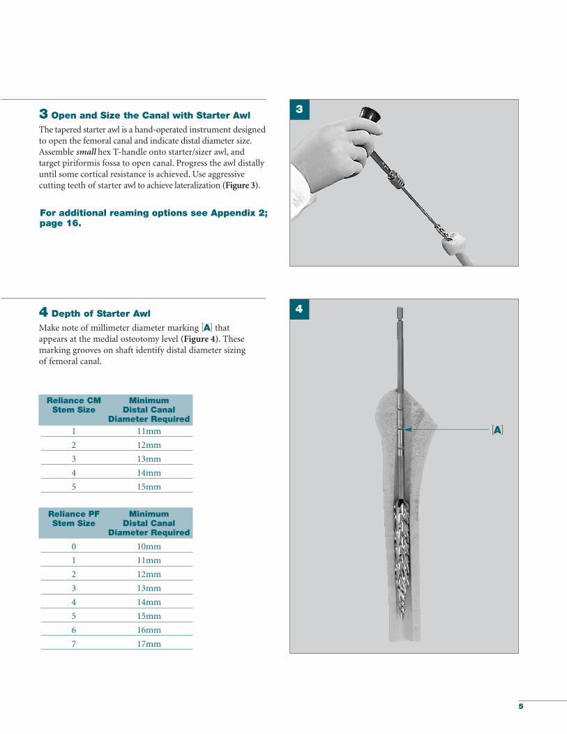
3 Open and Size the Canal with Starter Awl
The tapered starter awl is a hand-operated instru ment designedto open the femoral canal and indicate distal diameter size. Assemble small hex T-handle onto starter/sizer awl, and target piriformis fossa to open canal. Progress the awl distallyuntil some cortical resistance is achieved. Use aggressive cutting teeth of starter awl to achieve lateralization (Figure 3).
4 Depth of Starter Awl
Make note of millimeter diameter marking [A] that appears at the medial osteotomy level (Figure 4). Thesemarking grooves on shaft identify distal diameter sizing of femoral canal.
Reliance CM MinimumStem Size Distal Canal
Diameter Required1 11mm
2 12mm
3 13mm
4 14mm
5 15mm
Reliance PF Minimum Stem Size Distal Canal
Diameter Required
0 10mm
1 11mm
2 12mm
3 13mm
4 14mm
5 15mm
6 16mm
7 17mm
[A]
For additional reaming options see Appendix 2;page 16.
3
4
549_09_LRCMST_Rev1_Reliance_Component_ST_Layout 1 4/12/10 11:22 AM Page 5
6
Reliance Femoral Component Surgical Protocol
Broaching
Reliance CM*/PF Fully Toothed Stem Size Broach Size
0 0
1 1
2 2
3 3
4 4
5 5
6 6
7 7
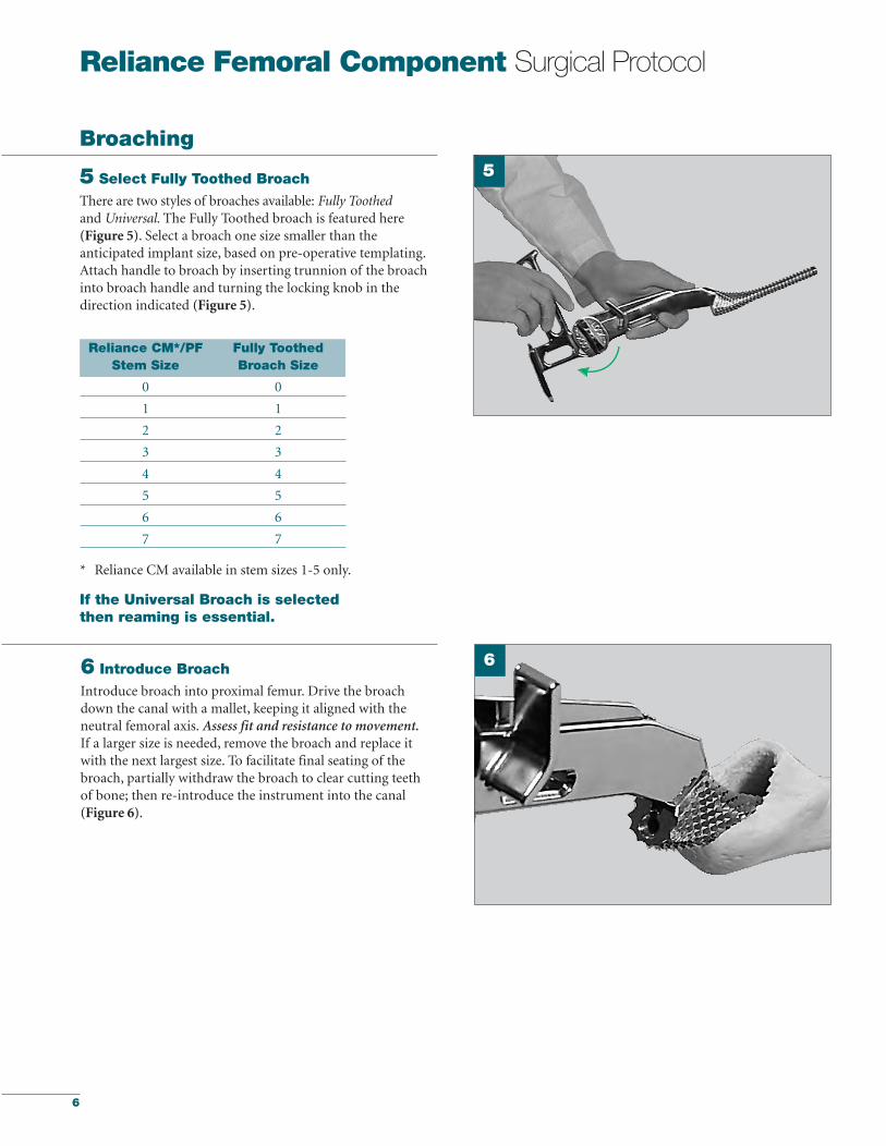
6 Introduce Broach
Introduce broach into proximal femur. Drive the broachdown the canal with a mallet, keeping it aligned with the neutral femoral axis. Assess fit and resistance to movement.If a larger size is needed, remove the broach and replace itwith the next largest size. To facilitate final seating of thebroach, partially withdraw the broach to clear cutting teethof bone; then re-introduce the instrument into the canal(Figure 6).
5
* Reliance CM available in stem sizes 1-5 only.
6
5 Select Fully Toothed Broach
There are two styles of broaches available: Fully Toothedand Universal. The Fully Toothed broach is featured here (Figure 5). Select a broach one size smaller than theanticipated implant size, based on pre-operative templating.Attach handle to broach by inserting trunnion of the broachinto broach handle and turning the locking knob in thedirection indicated (Figure 5).
If the Universal Broach is selectedthen reaming is essential.
549_09_LRCMST_Rev1_Reliance_Component_ST_Layout 1 4/12/10 11:22 AM Page 6

7
7 Calcar Planer
Leave the final broach seated in the canal. Remove the broachhandle. The broach trunnion may be used as a guide for thecalcar planer. The calcar planers come in two sizes: standardand large. Select the proper size planer and assemble it to thepower adaptor. The female bushing on the planer is guidedover the broach trunnion (Figure 7). The medial calcarshould be leveled to aid the collar calcar contact.
8 Fit Neck Trial to Trunnion
Select the appropriate size V40 neck trial corresponding tothe broach/implant size and push the trunnion securely ontothe broach (Figure 8).
To prepare the femur for the Reliance CM Stem using a cemented procedure proceed to Step 9C on page 8.
To prepare the femur for the Reliance PF Stem using a press-fit procedure proceed to Step 9PF on page 10.
7
8
549_09_LRCMST_Rev1_Reliance_Component_ST_Layout 1 4/12/10 11:22 AM Page 7

8
Reliance Femoral Component Surgical Protocol
9C Trial Reduction
Select the head diameter [26mm, 28mm, 32mm, 36mm,40mm or 44mm] according to surgeon preference. The V40head trials have a circumferential groove which identifies thelevel of the center of rotation. Select the femoral head offsetoption* based on pre-operative templating. Attach the headtrial to the neck trial and perform a trial reduc tion, assessingthe hip for stability, leg length, and overall range of motion.Remove the broach and all trials.
*Femoral Head offset options may vary depending on diameter size and material composition.
Reliance CM CompletionSee pages 10 & 11 for surgical implantation of the Reliance PF (press-fit) implant.
10C Insert Cement
Thoroughly clean and dry the canal. Insert a bone plug to alevel 2cm distal to end of stem. Prepare the bone cement.Pump cement into the canal in retrograde fashion, retractingthe nozzle as back pressure is felt (Figure 10C). When thecanal is filled with cement, place the appropriate pressurizingseal in the mouth of femur. Slide the cement nozzle throughthe seal and introduce remaining cement under pressure. Retain a small bolus of bone cement to serve as guide to knowwhen the cement in the canal has cured.
Reliance CM is designed for cemented applications. To complete the surgery with a Reliance CM implant the following steps (9C thru 13C) should be followed:
9C
10C
549_09_LRCMST_Rev1_Reliance_Component_ST_Layout 1 4/12/10 11:22 AM Page 8
9
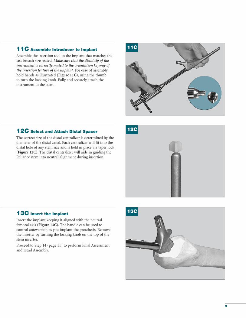
13C Insert the Implant
Insert the implant keeping it aligned with the neutral femoral axis (Figure 13C). The handle can be used to control anteversion as you implant the prosthesis. Removethe inserter by turning the locking knob on the top of thestem inserter.
Proceed to Step 14 (page 11) to perform Final Assessment and Head Assembly.
11C Assemble Introducer to Implant
Assemble the insertion tool to the implant that matches thelast broach size seated. Make sure that the distal tip of theinstrument is correctly mated to the orientation keyway of the insertion feature of the implant. For ease of assembly,hold hands as illustrated (Figure 11C), using the thumb to turn the locking knob. Fully and securely attach theinstrument to the stem.
12C Select and Attach Distal Spacer
The correct size of the distal centralizer is determined by thediameter of the distal canal. Each centralizer will fit into thedistal hole of any stem size and is held in place via taper lock(Figure 12C). The distal centralizer will aide in guiding theReliance stem into neutral alignment during insertion.
11C
13C
12C
549_09_LRCMST_Rev1_Reliance_Component_ST_Layout 1 4/12/10 11:22 AM Page 9
10
Reliance Femoral Component Surgical Protocol
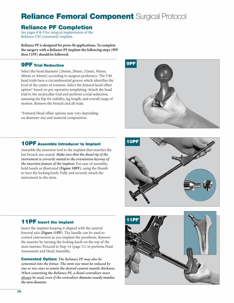
10PF Assemble Introducer to Implant
Assemble the insertion tool to the implant that matches thelast broach size seated. Make sure that the distal tip of the instrument is correctly mated to the orientation keyway of the insertion feature of the implant. For ease of assembly,hold hands as illustrated (Figure 10PF), using the thumb to turn the locking knob. Fully and securely attach the instrument to the stem.
9PF Trial Reduction
Select the head diameter [26mm, 28mm, 32mm, 36mm,40mm or 44mm] according to surgeon preference. The V40head trials have a circumferential groove which identifies thelevel of the center of rotation. Select the femoral head offsetoption* based on pre-operative templating. Attach the headtrial to the neck/collar trial and perform a trial reduction,assessing the hip for stability, leg length, and overall range ofmotion. Remove the broach and all trials.
*Femoral Head offset options may vary dependingon diameter size and material composition.
11PF Insert the Implant
Insert the implant keeping it aligned with the neutral femoral axis (Figure 11PF). The handle can be used tocontrol anteversion as you implant the prosthesis. Removethe inserter by turning the locking knob on the top of thestem inserter. Proceed to Step 14 (page 11) to perform FinalAssessment and Head Assembly.
Cemented Option: The Reliance PF may also becemented into the femur. The stem size must be reduced byone or two sizes to attain the desired cement mantle thickness.When cementing the Reliance PF, a distal centralizer mustalways be used, even if the centralizer diameter exactly matchesthe stem diameter.
Reliance PF is designed for press-fit applications. To completethe surgery with a Reliance PF implant the following steps (9PFthru 11PF) should be followed:
9PF
10PF
11PF
Reliance PF CompletionSee pages 8 & 9 for surgical implantation of the Reliance CM (cemented) implant.
549_09_LRCMST_Rev1_Reliance_Component_ST_Layout 1 4/12/10 11:22 AM Page 10

11
Final Assessment
14 Final Trial Reduction
Prior to head assembly, head offset selection may bere-evaluated using a Stryker V40 Trial Head. Place the TrialHead onto the stem neck taper and reduce the hip to verifythat the mechanics have not been altered due to implantseating. (Figure 14).
15 Head Assembly
Remove the Trial Head and dry the implant trunnion with alaparatomy sponge or sterile towel.
Select the appropriate corresponding V40 Femoral Head sizeand place it onto the dry trunnion of the femoral stem with aslight twist. Impact the head with two moderate blows usingthe Femoral Head Impactor (Figure 15).
NOTE:Only Stryker V40 femoral heads labeled as 5° 40'taper may be used with the stems in the partnership system.
NOTE: The Reliance PF and CM stems can be used with either a V40 CoCr Femoral Head, a BIOLOX delta FemoralHead, a Biolox delta Universal Head and a V40 UniversalAdaptor Sleeve, or a Titanium Adapter Sleeve and an AluminaCeramic C-Taper Femoral Head.
14
15
549_09_LRCMST_Rev1_Reliance_Component_ST_Layout 1 4/12/10 11:22 AM Page 11

12
Reliance Femoral Component Surgical Protocol
V40 Universal Adapter Offset Stem MaterialSleeve Part Numbers Compatibility
6519-T-025 -2.5mm TMZF, Ti6-4, CoCr
6519-T-100 +0 TMZF, Ti6-4, CoCr
6519-T-204 +4 mm TMZF, Ti6-4, CoCr
Optional StepNOTE: When selecting a BIOLOX deltaUniversal Taper Ceramic Femoral Headfor implantation, use of a Universal Adaptor Sleeve is necessary.
After completing the trialing process, intra-operativelyassemble the Adaptor Sleeve to the femoral stem manually.
The Universal Adaptor Sleeve must be fully seated onthe stem taper before the head is assembled.
NOTE: In no instance should any attemptbe made to pre-assemble the BIOLOXdelta Universal Ceramic head.
Intra-operatively assemble the BIOLOX delta UniversalTaper Ceramic head onto the sleeved femoral stem andset with one to three moderate blows using theFemoral Head Impactor. Care must be taken to avoidexcessive impact forces when assembling the CeramicHead to the sleeved femoral component.
Universal Adapter Sleeves
16 Reduce Joint and Close
Relocate the femoral head into the acetabular cup and checkthe laxity and range of motion. The surgical site is then closed according to the surgeon’s standard procedure for thesurgical approach chosen.
Head Assembly (Continued)
549_09_LRCMST_Rev1_Reliance_Component_ST_Layout 1 4/12/10 11:22 AM Page 12
13
#1#2#3#4#5
Stem Size
39mm40mm42mm43mm45mm
43mm44mm46mm47mm49mm
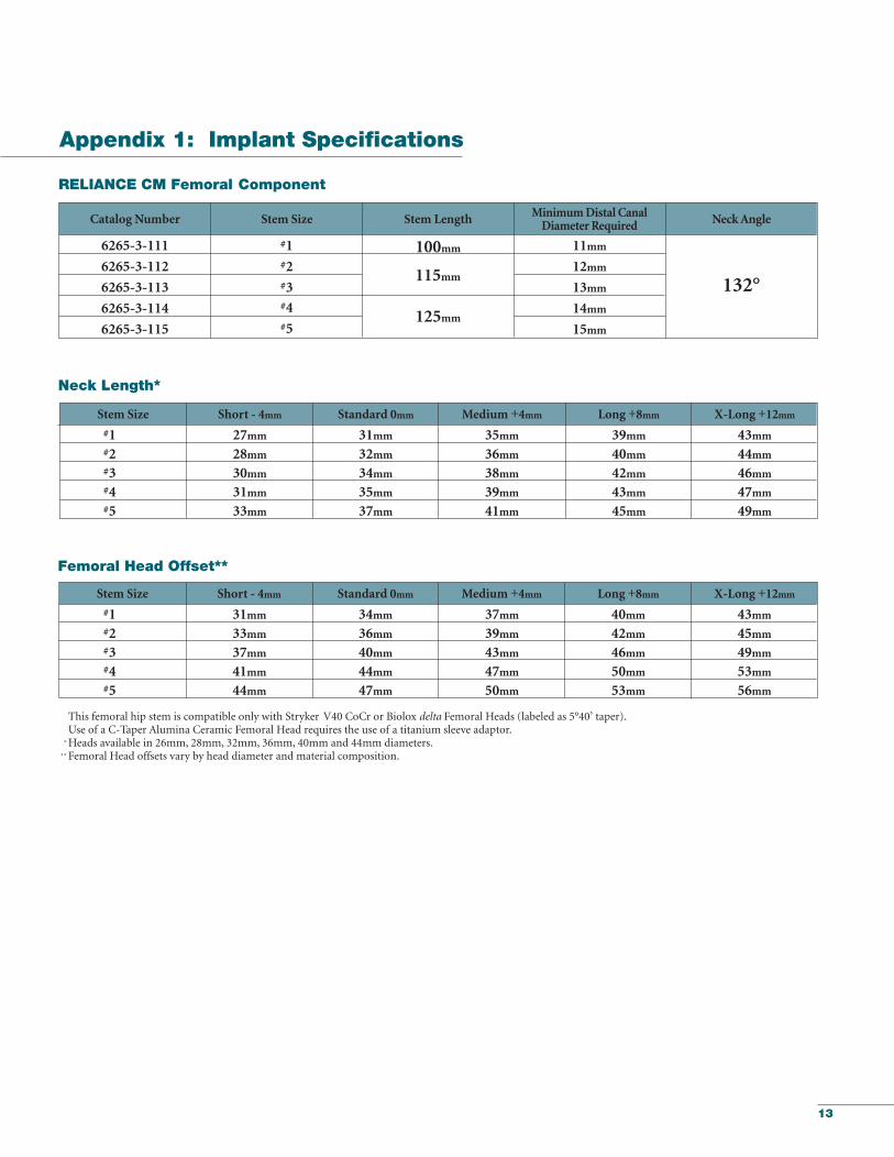
Neck Length*
Standard 0mmShort - 4mm Medium +4mm Long +8mm X-Long +12mm
27mm28mm30mm31mm33mm
31mm32mm34mm35mm37mm
35mm36mm38mm39mm41mm
#1#2#3#4#5
Stem Size
40mm42mm46mm50mm53mm
43mm45mm49mm53mm56mm
Femoral Head Offset**
Standard 0mmShort - 4mm Medium +4mm Long +8mm X-Long +12mm
31mm33mm37mm41mm44mm
34mm36mm40mm44mm47mm
This femoral hip stem is compatible only with Stryker V40 CoCr or Biolox delta Femoral Heads (labeled as 5°40’ taper). Use of a C-Taper Alumina Ceramic Femoral Head requires the use of a titanium sleeve adaptor.
*Heads available in 26mm, 28mm, 32mm, 36mm, 40mm and 44mm diameters. ** Femoral Head offsets vary by head diameter and material composition.
37mm39mm43mm47mm50mm
132°
125mm
115mm
100mm
RELIANCE CM Femoral Component
Minimum Distal Canal Diameter Required Neck Angle
#1#2#3#4#5
Stem LengthStem Size
11mm
12mm
13mm
14mm
15mm
Catalog Number
6265-3-111
6265-3-112
6265-3-113
6265-3-114
6265-3-115
Appendix 1: Implant Specifications
549_09_LRCMST_Rev1_Reliance_Component_ST_Layout 1 4/12/10 11:22 AM Page 13

14
#0#1#2#3#4#5#6#7
Stem Size
40mm40mm42mm46mm50mm53mm56mm58mm
43mm43mm45mm49mm53mm56mm59mm61mm
Femoral Head Offset**
Standard 0mm Medium +4mm Long +8mm X-Long +12mm
34mm34mm36mm40mm44mm47mm50mm52mm
This femoral hip stem is compatible only with Stryker V40 CoCr or Biolox delta Femoral Heads (labeled as 5°40’ taper). Use of a C-Taper Alumina Ceramic Femoral Head requires the use of a titanium sleeve adaptor.
*Heads available in 26mm, 28mm, 32mm, 36mm, 40mm and 44mm diameters. ** Femoral Head offsets vary by head diameter and material composition.
37mm37mm39mm43mm47mm50mm53mm55mm
#0#1#2#3#4#5#6#7
Stem Size
39mm39mm40mm42mm43mm45mm45mm47mm
43mm43mm44mm46mm47mm49mm49mm51mm
Neck Length*
Standard 0mmShort -4mm Medium +4mm Long +8mm X-Long +12mm
27mm27mm28mm30mm31mm33mm33mm35mm
31mm31mm32mm34mm35mm37mm37mm39mm
35mm35mm36mm38mm39mm41mm41mm43mm
132°140mm
130mm
115mm
RELIANCE PF Femoral Component
Minimum Distal Canal Diameter Required Neck AngleStem LengthStem Size
150mm
10mm
11mm
12mm
13mm
14mm
15mm
16mm
17mm
Catalog Number
6265-2-000
6265-2-001
6265-2-002
6265-2-003
6265-2-004
6265-2-005
6265-2-006
6265-2-007
Short -4mm
31mm31mm33mm37mm41mm44mm47mm49mm
Appendix 1 (Continued)
Reliance Femoral Component Surgical Protocol
#0#1#2#3#4#5#6#7
549_09_LRCMST_Rev1_Reliance_Component_ST_Layout 1 4/12/10 11:22 AM Page 14
15
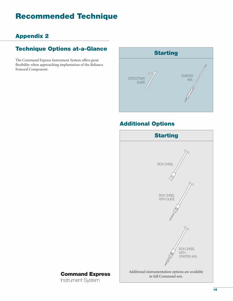
Starting
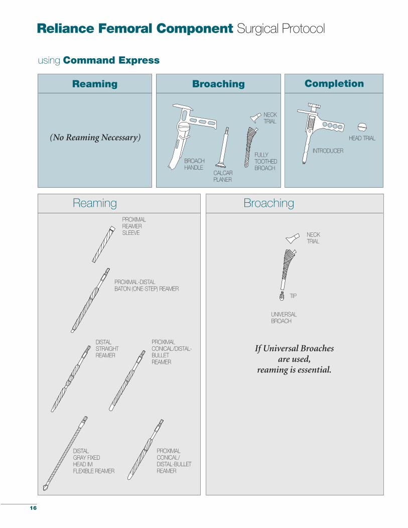
Technique Options at-a-Glance
The Command Express Instrument System offers great flexibility when approaching implantation of the RelianceFemoral Component.
Additional instrumentation options are available in full Command sets.
Starting
STARTERAWLOSTEOTOMY
GUIDE
BOX CHISEL
BOX CHISELWITH STARTER AWL
Recommended Technique
Additional Options
BOX CHISELWITH GUIDE
Command ExpressInstrument System
Appendix 2
549_09_LRCMST_Rev1_Reliance_Component_ST_Layout 1 4/12/10 11:22 AM Page 15
16
Reliance Femoral Component Surgical Protocol
Reaming Broaching
Reaming Broaching
HEAD TRIAL
INTRODUCER
DISTALSTRAIGHTREAMER
PROXIMAL-DISTALBATON (ONE-STEP) REAMER
PROXIMALCONICAL/DISTAL-BULLET REAMER
DISTALGRAY FIXEDHEAD IMFLEXIBLE REAMER
FULLYTOOTHEDBROACH
NECKTRIAL
BROACHHANDLE
CALCARPLANER
UNIVERSALBROACH
TIP
NECKTRIAL
Completion
If Universal Broaches are used,
reaming is essential.
using Command Express
PROXIMALCONICAL/DISTAL-BULLET REAMER
PROXIMALREAMERSLEEVE
(No Reaming Necessary)
549_09_LRCMST_Rev1_Reliance_Component_ST_Layout 1 4/12/10 11:22 AM Page 16

17
Notes
549_09_LRCMST_Rev1_Reliance_Component_ST_Layout 1 4/12/10 11:22 AM Page 17

18
Notes
549_09_LRCMST_Rev1_Reliance_Component_ST_Layout 1 4/12/10 11:22 AM Page 18

549_09_LRCMST_Rev1_Reliance_Component_ST_Layout 1 4/12/10 11:22 AM Page 19

325 Corporate DriveMahwah, NJ 07430t: 201 831 5000
www.stryker.com
A surgeon must always rely on his or her own professional clinical judgment when deciding whether to use aparticular product when treating a particular patient. Stryker does not dispense medical advice and recommendsthat surgeons be trained in the use of any particular product before using it in surgery.
The information presented is intended to demonstrate the breadth of Stryker product offerings. A surgeon mustalways refer to the package insert, product label and/or instructions for use before using any Stryker product.Products may not be available in all markets because product availability is subject to the regulatory and/ormedical practices in individual markets. Please contact your Stryker representative if you have questions about the availability of Stryker products in your area.
Stryker Corporation or its divisions or other corporate affiliated entities own, use or have applied for the followingtrademarks or service marks: Biolox delta, Command, Gray, Partnership, Reliance, Stryker and V40. All othertrademarks are trademarks of their respective owners or holders.
Literature Number: LRCMST Rev. 1MS/GS 04/10
Copyright © 2010 StrykerPrinted in USA
549_09_LRCMST_Rev1_Reliance_Component_ST_Layout 1 4/12/10 11:22 AM Page 20