Reliability and Availablity
6
Reliability and Availablity This set of notes is a combination of material from Prof. Doug Carmichael's notes for 13.21 and Chapter 8 of Engineering Statistics Handbook . NIST/SEMATECH e-Handbook of Statistical Methods, http://www.itl.nist.gov/div898/handbook/ , 2005. available free from: see: NIST/SEMATECH e-Handbook of Statistical Methods on CD Including and improving reliability of propulsion (and other) systems is a challenging goal for system designers. An approach has developed to tackle this challenge: 1. a design and development philosophy 2. a test procedure for components and total systems 3. a modelling procedure based on test results, field tests and probability (statistics Design and development philosophy recognition that reliability is a product is essentiall the abscence of failures or substandard performance of all critical systems in the design, followed by an examination of the factors leading to failure. Causes of failure: a. loading: (inaccurate estimates of) thermal, mechanical or electriacl including vibrations b. strength: (inaccurate estimates of) the load carrying capacity of the components c. environment: presence of dirt, high temperature, shock, corrosion, moisture, etc. d. human factors: heavy handed operators ("sailor proof"), wrong decisions (operator error), criminal activities (sabatoge), poor design, tools left in critical components, use of incorect replacements e. quality control: or lack thereof; loose control of materials and manufacture, lack of inspection, loose specifications f. accident; act of God, freak accidents, collisions g. acts of war: terorism, war damage designer should recognize these potential causes for failure and try to design devices that will resist failure. Detailed Design Features a. try to account for all possible situations in the design stage and eliminate possible failures. Delivering maximumloads and minimum strengths b. assume that every component can fail, examine the outcome of the failure and try to reduce the risk of damage. Failure Modes and Effects Analysis (FEMA) c. institute strict quality control in manufacture and maintenance d. have cleaarly defined specifications (including material specifications and methods of testing) e. develop technology to meet new challenges. conduct development testing. f. consider possible war damage and ship collision g. carry out development testing in arduous conditions System Design Features a. calculate probability of failures. (reliability and availability analysis b. improve system design by standby or redundant systems c. analyze failures, note trends d. specify clearly all operating procedures (good operating manuals) e. require inspection, maintenance and replacement procedures (trend analysis) Failure testing and analysis from field or laboratory tests on components or systems determine number of operating units as a function of time (life): 12/13/2005 1
-
Upload
firdaus-bin-mahamad -
Category
Documents
-
view
217 -
download
0
Transcript of Reliability and Availablity
8/3/2019 Reliability and Availablity
http://slidepdf.com/reader/full/reliability-and-availablity 1/6
Reliability and Availablity
This set of notes is a combination of material from Prof. Doug Carmichael's notes for 13.21 and Chapter 8 ofEngineering Statistics Handbook . NIST/SEMATECH e-Handbook of Statistical Methods,http://www.itl.nist.gov/div898/handbook/ , 2005.available free from:see: NIST/SEMATECH e-Handbook of Statistical Methods on CD
Including and improving reliability of propulsion (and other) systems is a challenging goal for system designers.
An approach has developed to tackle this challenge:
1. a design and development philosophy
2. a test procedure for components and total systems
3. a modelling procedure based on test results, field tests and probability (statistics
Design and development philosophy recognition that reliability is a product is essentiall the abscence of failures or substandard performance of all critical systems in the design, followed by an examination of the factors leading to failure. Causes of failure: a. loading: (inaccurate estimates of) thermal, mechanical or electriacl including
vibrationsb. strength: (inaccurate estimates of) the load carrying capacity of the components
c. environment: presence of dirt, high temperature, shock, corrosion, moisture, etc.
d. human factors: heavy handed operators ("sailor proof"), wrong decisions (operator error), criminal activities(sabatoge), poor design, tools left in critical components, use of incorect replacementse. quality control: or lack thereof; loose control of materials and manufacture, lack of inspection, loose specificationsf. accident; act of God, freak accidents, collisions
g. acts of war: terorism, war damage
designer should recognize these potential causes for failure and try to design devices that will resist failure.
Detailed Design Features a. try to account for all possible situations in the design stage and eliminate possible failures. Delivering maximumloads and minimum strengthsb. assume that every component can fail, examine the outcome of the failure and try to reduce the risk of damage. Failure Modes and Effects Analysis (FEMA)c. institute strict quality control in manufacture and maintenance
d. have cleaarly defined specifications (including material specifications and methods of testing)
e. develop technology to meet new challenges. conduct development testing.
f. consider possible war damage and ship collision
g. carry out development testing in arduous conditions
System Design Features
a. calculate probability of failures. (reliability and availability analysisb. improve system design by standby or redundant systems
c. analyze failures, note trends
d. specify clearly all operating procedures (good operating manuals)
e. require inspection, maintenance and replacement procedures (trend analysis)
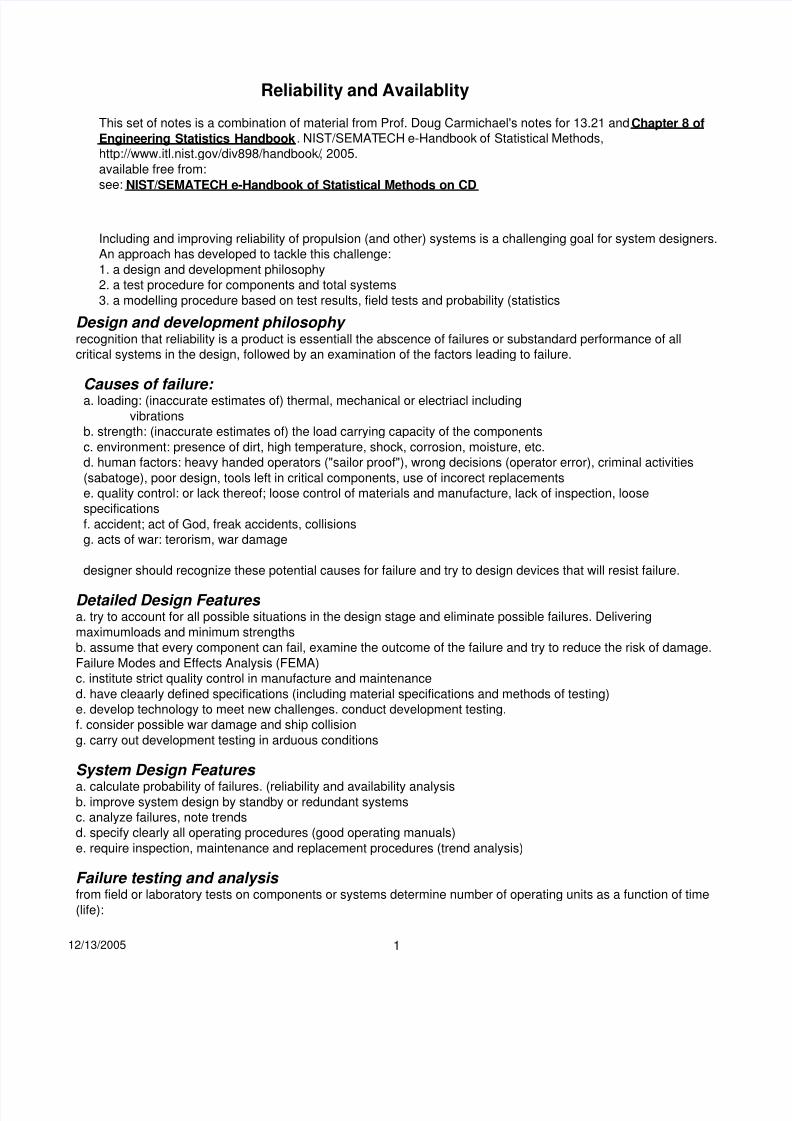
Failure testing and analysis from field or laboratory tests on components or systems determine number of operating units as a function of time (life):
12/13/2005 1
8/3/2019 Reliability and Availablity
http://slidepdf.com/reader/full/reliability-and-availablity 2/6
set up N_surv
nominal survival curve
20 40 60 80 100
time
- as "rate" > 0 consistent with time− 1
population decline units are:
N t( ) ⎞ ⎮⌠ t
λ τ dτ ( ) = ⋅ ⎛ ⎮⌠ t
λ τ dτ ⎞
N 0( ) ⎠ = −⌡
0
( ) N t NI exp −⌡
0
( ) ⎝ ⎠
calculate for modest δt = 0.01 and t =10, 40,
60, 120
100
80
60
40
200
−1 d⋅ N t( )N t( ) dt
⎛ ln
⎝ N t( + δt) − N t( )
a typical survival curve might
look like this:
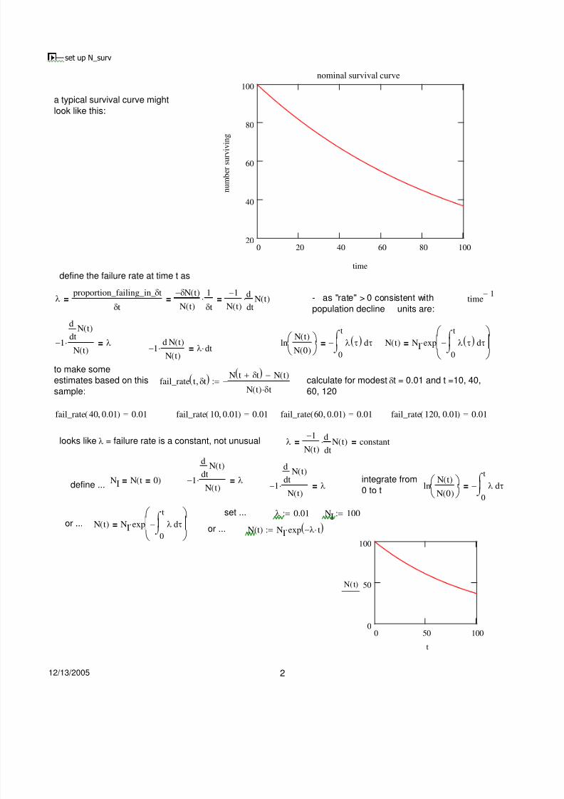
define the failure rate at time t asproportion_failing_in_δt −δN t( ) 1
λ = = ⋅ =
n u m b e r s u r v i v i n
g
fail_rate t( , δt) := − N t( )⋅δt
δt
dN t( )
dt−1⋅ = λ
N t( )
to make some
estimates based on this
sample:
fail_rate 40 0.01( , ) = 0.01
N t( ) δt
d N t( )−1⋅ = λ⋅ dt
N t( )
fail_rate 10 0.01( , ) = 0.01 ( , ) = 0.01 ( , ) = 0.01fail_rate 60 0.01 fail_rate 120 0.01
looks like λ = failure rate is a constant, not unusual
dN t( )
dt
define ...NI = N t( = 0) −1⋅ = λ
N t( )
⎛ ⌠ t ⎞ set ...
or ... N t( ) = NI⋅exp −⎮ λ dτ or ... N( )t⎝ ⌡
0 ⎠
−1 dλ = ⋅ N t( ) = constantN t( ) dt
d
dtN t( )
integrate from ⎛ N t( ) ⎞ ⌠ t−1⋅
N t( )= λ
0 to tln
( ) ⎠ = −⎮⌡
0
λ dτ ⎝ N 0
Iλ := 0.01 N := 100
:= NI⋅exp(−λ⋅ t) 100
N t( ) 50
00 50 100
t
12/13/2005 2

8/3/2019 Reliability and Availablity
http://slidepdf.com/reader/full/reliability-and-availablity 3/6
0
1
2
f a i l u r e r a t e
100 800
N.B. failure rate is not necessarily the same as (but can be related to) (in this case it is) the probability of failure see Engineering Statistics Handbookan actual failure rate curve might look like this:
set up bath tub
nominal failure rate
three regions are evident:
0 - 100 early failure period = infant mortality
rate
100 - 800 intrinsic failure period aka stable
failure period => intrinsic failure rate
> 800 wearout failure period - materials wear out
and degradation failures occur at an ever
0 200 400 600 800 1000 increasing rate
for most systems, the failure rate is relatively constant except for wer in and wear out. If the failure rate is constant, the component is said to have random failure.time
Reliability (applies to a particular mission with a defined duration.)defined as the probability of operating without degraded performance during a specific time period. At time t 1, thenumber operating is N(t1) and NI is the initial number. The reliability is:
N t1 N t1 ⌠ t1 N t1
⎛ ⌠ t1 ⎞( ) d N t( ) ⎛ ( ) ⎞ ( )
R t1 = since ... −1⋅ = λ⋅dt ln = −⎮ λ dt R t1 = = exp −⎮ λ dt( ) N
I
N t( )
⎝ N
I ⎠ ⌡
0
( ) N
I ⎝ ⌡
0 ⎠ with λ = constant
( ) exp(− t1) and expanding( ) 1
(λ⋅t1)2
(λ⋅ t1)3
R t1 = λ⋅ in a series ...
R t1 = − λ⋅ t1 + 2!
− 3!
+ ..
and if ... λ*t1 << 1, R t1 = − ⋅ e.g. λ := 0.05 1 − λ = 0.95 exp λ = 0.951( ) 1 λ t1 t1 t1 (− t1) Mean Time Between (Operational Mission) Failure (MTB(OM)F
with field testing,data is collected in the form of operating time, failures and repair time.
During the field operation of a component or a system, there is a total number of operating hours and a total
number of failures. MTB(OM)F is defined
accumulated_lifeMBT OM( ) F =
number_of_failuresnumber_of_failures 1
For random failures, the failure rateλ =
accumulated_life=
MBT OM) F (
if ...t1
( ) 1t1
< 1 R t1 = − λ⋅ t1 = 1 −MBT OM) F ( ⋅( MBT OM) F
12/13/2005 3

8/3/2019 Reliability and Availablity
http://slidepdf.com/reader/full/reliability-and-availablity 4/6
Probability of Failure (Q or F) t1 if ... λ*t1
since probability of success + failure = 1 R + Q = 1 Q 1 − R = 1 − exp(−λ⋅ ) = λ⋅ t1 =<< 1
= t1MTBF
now consider separate components C1 and C2 having R1 and R2 and Q1 and Q2. then ...
(R1 + Q1)⋅(R2 + Q2) = 1 (R1 + Q1)⋅(R2 + Q2) expand → R1⋅R2 + R1⋅Q2 + Q1⋅R2 + Q1⋅Q2
R1⋅R2 = probability_both_C1_and_C2_operating
R1⋅Q2 = probability_C1_operating_and_C2_failed
R2⋅Q1 = probability_C2_operating_and_C1_failed
Q1⋅Q2 = probability_C1_and_C2_failed
Series Systems
If it is necessary for all systems to operate, then this termed a series system and is represented as a circuit as:
From above; the probability that both are operating is ... Rseries = R1⋅R2
more generally,Rseries = R1⋅R2⋅R3 .. Rn = exp⎡−∑ (λi⋅t1)⎤ = ∏ Ri
⎣ n ⎦ ne.g. ... R1 := 0.9 R2 := 0.9 R3 := 0.9 2 components R1⋅R2 = 0.81
Rn := 0.9
6 components R
n
6= 0.531
Parallel Systems
If there is redundancy, and either C1 or C2 is required for operation then this is a parallel scheme ...
Rparallel = R1⋅R2 + R1⋅Q2 + Q1⋅R2 = 1 − Q1⋅Q2
generally ...Rparallel = 1 − Q1⋅Q2⋅Q3 .. Qn = 1 − ∏ Qi
when Qi = Qn Rparallel = 1 − Qin
ne.g. ... R1 0.9:= R2 0.9:= R3 0.9:= Qi 0.1:=
nR := 0.9
2 components 1 − Qi2
= 0.99
12/13/2005 4

8/3/2019 Reliability and Availablity
http://slidepdf.com/reader/full/reliability-and-availablity 5/6
R out of N see Handbook of Statistical Methods section 8.1.8.4.R out of N model
If a system has n components and reqires any r to be operational; assuming
all components have thesame reliability Ri
all components operate independent of one another (as far as failure is concerned)
the system can survive any (n - r) components failing, but fails at the instant the n - r - 1)th component fails
System reliability is given by the probability of exactly r components surviving to time t + the probability of exactly (r
+ 1) components surviving to time t ... up to all n surviving. These are binomial probabilities:
n⎡⎛ ⎞ i
)n i
Rs( )t = ∑ n⋅Ri ⋅(1 − Ri
−⎤⎣⎝ r ⎠ ⎦
i = rfor example (where Ri are not n = 4 r = 2 i.e. four components of which two arenecessarily equal ... required for operation
2 components R1⋅R2⋅Q3⋅Q4 + R1⋅R3⋅Q2⋅Q4 + R1⋅R4⋅Q2⋅Q3 + R2⋅R3⋅Q1⋅Q4 + R2⋅R4⋅Q1⋅Q3 + R3⋅R4⋅Q1⋅Q23 components
R1⋅R2⋅R3⋅Q4 + R1⋅R3⋅R4⋅Q2 + R1⋅R2⋅R4⋅Q3 + R2⋅R3⋅R4⋅Q1n = 4 components R1⋅R2⋅R3⋅R4
sum all these for Rs
Rs = R1⋅R2⋅Q3⋅Q4 + R1⋅R3⋅Q2⋅Q4 + R1⋅R4⋅Q2⋅Q3 + R2⋅R3⋅Q1⋅Q4 + R2⋅R4⋅Q1⋅Q3 + R3⋅R4⋅Q1⋅Q2 ... + R1⋅R2⋅R3⋅Q4 + R1⋅R3⋅R4⋅Q2 + R1⋅R2⋅R4⋅Q3 + R2⋅R3⋅R4⋅Q1 ... + R1⋅R2⋅R3⋅R4
N.B. a series system is one with r = n i.e. all components must operate. a parallel system is one with r = 1
Standby Systems
Standby scenario will be more reliable than parallel as seen in Handbook of Statistical Methods section8.1.8.5.Standby modelAvailability
Availability is the probability that a component is operational, i.e. it is not being repaired
MTTR = mean_time_to_repair =total_time_for_repairs
number_of_repairsFor every failure there should be a repair, so that the average component is repaired for the average time after ithas operated for the average time between failures. Average time between failures is MTBF and for repair MTTR,
so assuming component is either operating or being repaired ...
availability = A =operating_time
=MTBF
operating_time + repair_time MTBF + MTTR
MTBF > MTTR ( << ) which it should be ...if ...
12/13/2005 5

8/3/2019 Reliability and Availablity
http://slidepdf.com/reader/full/reliability-and-availablity 6/6
A =MTBF
= 1 − MTTR 1= (1 + a)
− 1= 1 − a a 1 ( << )<
MTBF + MTTR MTBF 1 + a
MTTRprobability that it is being repaired is ... QA QA = 1 − A =
MTBF
and as above, availability for series systems would be ..
Aseries = A1⋅A2⋅A3 .. An =
∏Ai
n
and parallel ...= 1 − ⋅ ⋅ .. = 1Aparallel Q1 Q2 Q3 Qn − ∏ Qi
n
12/13/2005 6