RELEASED Prin Stennis Space Center tedocuments may … · · 2013-04-10March 8, 2006 2 Stennis...
39
RELEASED - Printed documents may be obsolete; validate prior to use. RELEASED - Printed documents may be obsolete; validate prior to use. Stennis Space Center Emerging Techniques for Vicarious Calibration of Visible Through Short Wave Infrared Remote Sensing Systems Presented by Robert E. Ryan Science Systems and Applications, Inc. John C. Stennis Space Center 2006 EO/IR Calibration and Characterization Workshop Logan, UT, USA March 7-9, 2006 https://ntrs.nasa.gov/search.jsp?R=20060019231 2018-06-10T21:59:36+00:00Z
-
Upload
hoangthuan -
Category
Documents
-
view
218 -
download
3
Transcript of RELEASED Prin Stennis Space Center tedocuments may … · · 2013-04-10March 8, 2006 2 Stennis...
RE
LE
AS
ED
- Prin
ted d
ocu
men
ts may b
e ob
solete; valid
ate prio
r to u
se.R
EL
EA
SE
D - P
rinted
do
cum
ents m
ay be o
bso
lete; validate p
rior to
use.
Stennis Space Center
Emerging Techniques for Vicarious Calibration of Visible Through Short
Wave Infrared Remote Sensing Systems
Presented by Robert E. Ryan
Science Systems and Applications, Inc.John C. Stennis Space Center
2006 EO/IR Calibration and Characterization Workshop Logan, UT, USA March 7-9, 2006
https://ntrs.nasa.gov/search.jsp?R=20060019231 2018-06-10T21:59:36+00:00Z

March 8, 2006 2
Stennis Space Center
• SSAI– Gary Harrington– Kara Holekamp– Mary Pagnutti
• NASA SSC
te prio
– Tom Stanley– Troy Frisbie
RE
LE
AS
ED
- Prin
ted d
ocu
men
ts may b
e ob
solete; valid
ar to
use.
RE
LE
AS
ED
- Prin
ted d
ocu
men
ts may b
e ob
solete; valid
ate pri
Contributors
or to
use.

March 8, 2006 3
Stennis Space CenterTopics
• Background• Emerging Cal/Val needs
s may
• Current vicarious calibration techniques• Radiative transfer validation• Alternative sun photometers
alidate
• LED-based calibration sources
prio
r t
• Summary
RE
LE
AS
ED
- Prin
ted d
ocu
men
tb
e ob
solete; v
o u
se.R
EL
EA
SE
D - P
rinted
do
cum
ents m
ay be o
bso
lete; validate p
rior to
use.
RE
LE
AS
ED
- Prin
ted d
ocu
men
ts may b
e ob
solete; valid
ate prio
r to u
se.R
EL
EA
SE
D - P
rinted
do
cum
ents m
ay be o
bso
lete; validate p
rior to
use.
March 8, 2006 4
Stennis Space CenterBackground
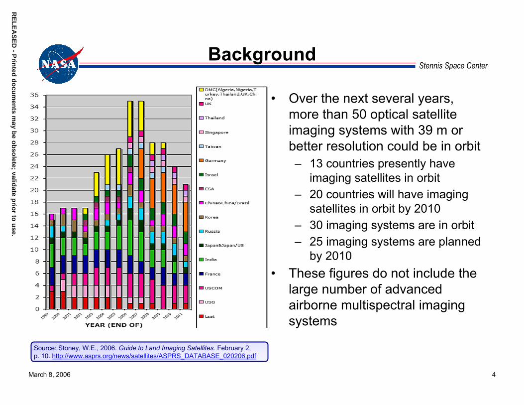
• Over the next several years, more than 50 optical satellite imaging systems with 39 m or better resolution could be in orbit– 13 countries presently have
imaging satellites in orbit– 20 countries will have imaging
satellites in orbit by 2010 – 30 imaging systems are in orbit – 25 imaging systems are planned
by 2010• These figures do not include the
large number of advanced airborne multispectral imaging systems
Source: Stoney, W.E., 2006. Guide to Land Imaging Satellites. February 2, p. 10. http://www.asprs.org/news/satellites/ASPRS_DATABASE_020206.pdf
March 8, 2006 5
Stennis Space CenterIssues
• The scientific community needs high-quality and well-understood image products– Geopositionally and radiometrically accurate products– Well-understood spatial resolution
• Insight into the system construction, calibration, and performance will be limited in many cases
• Most systems will not have any onboard radiometric calibration
e.
• Cal/Val (vicarious calibration) will be essential– Multiple approaches are desirable– Ground-based reflectance radiometric methods have the greatest
utility because all systems image the ground
RE
LE
AS
ED
- Prin
ted d
ocu
men
ts may b
e ob
solete; valid
ate prio
r to u
sR
EL
EA
SE
D - P
rinted
do
cum
ents m
ay be o
bso
lete; validate p
rior to
use.

March 8, 2006 6
Stennis Space CenterIssues (Cont.)
• Ground-based radiometric calibrations currently require teams of trained staff taking coincident data at the time of overpass and analysts to estimate Top-of-the-Atmosphere (TOA) radiance– Costly– Significant coordination is required between the imagery
provider and the calibration team– A variety of sites is needed
• Improved TOA radiance estimates are needed– Level of confidence in ground truth data is limited because
robust Cal/Val is lacking– Level of confidence in radiative transfer modeling is limited
because independent validation methods are lacking
RE
LE
AS
ED
- Prin
ted d
ocu
men
ts may b
e ob
solete; valid
ate prio
r to u
se.R
EL
EA
SE
D - P
rinted
do
cum
ents m
ay be o
bso
lete; validate p
rior to
use.

March 8, 2006 7
Stennis Space CenterIssues (Cont.)
• Robust automated systems are clearly needed to effectively calibrate and validate products from such a large number of systems– Several years away– Concerted, well-funded projects will need to be established
RE
LE
AS
ED
- Prin
ted d
ocu
men
ts may b
e ob
solete; valid
ate prio
r to u
se.R
EL
EA
SE
D - P
rinted
do
cum
ents m
ay be o
bso
lete; validate p
rior to
use.

March 8, 2006 8
Stennis Space CenterGround-based Radiometric Cal/Val Needs
• Near term– Increased confidence in ground truth and modeling through
multiple independent methods for validation– Measurement techniques that reduce or at least do not
increase staff– Simpler and more accurate calibration approaches
• Mid term
se.
– Development of techniques that are compatible with autonomous measurements
• Long term– Fully autonomous vicarious calibration techniques and sites
RE
LE
AS
ED
- Prin
ted d
ocu
men
ts may b
e ob
solete; valid
ate prio
r to u
RE
LE
AS
ED
- Prin
ted d
ocu
men
ts may b
e ob
solete; valid
ate prio
r to u
se.

RE
LE
AS
ED
- Prin
ted d
ocu
men
ts may b
e ob
solete; valid
ate prio
r to u
se.R
EL
EA
SE
D - P
rinted
do
cum
ents
March 8, 2006 9
Stennis Space CenterSSC Near Term Cal/Val Development Goals
• Improved accuracy and higher confidence in TOA radiance estimates – Radiative transfer modeling validation– Alternative sun photometer calibration and validation– Low-cost, simple, in-field, NIST-traceable radiometric
calibration source
may b
e ob
solete; valid
ate prio
r to u
se.
Autonomous approaches will evolve from improved, traditional, labor-intensive, radiometric calibrations
RE
LE
AS
ED
- Prin
ted d
ocu
men
ts may b
e ob
solete; valid
ate prio
r to u
se.R
EL
EA
SE
D - P
rinted
do
cum
ents m
ay be o
bso
lete; validate p
rior to
use.
March 8, 2006 10
Stennis Space CenterStennis Verification & Validation (V&V) Site
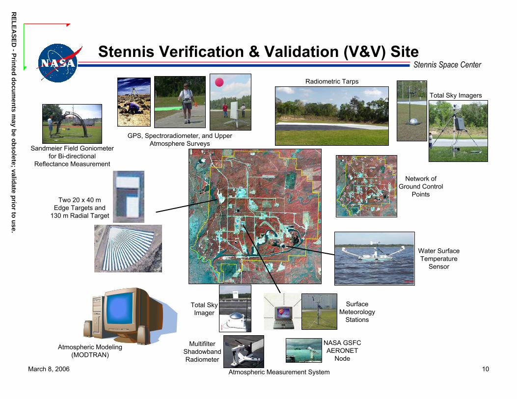
Sandmeier Field Goniometerfor Bi-directional
Reflectance Measurement
Network ofGround Control
Points
Radiometric Tarps
GPS, Spectroradiometer, and Upper Atmosphere Surveys
Total Sky Imagers
Two 20 x 40 mEdge Targets and
130 m Radial Target
Water SurfaceTemperature
Sensor
Atmospheric Modeling(MODTRAN)
Atmospheric Measurement System
MultifilterShadowbandRadiometer
Total SkyImager
NASA GSFCAERONET
Node
SurfaceMeteorology
Stations
RE
LE
AS
ED
- Prin
ted d
ocu
men
ts may b
e ob
solete; valid
ate prio
r to u
se.R
EL
EA
SE
D - P
rinted
do
cum
ents m
ay be o
bso
lete; validate p
rior to
use.
March 8, 2006 11
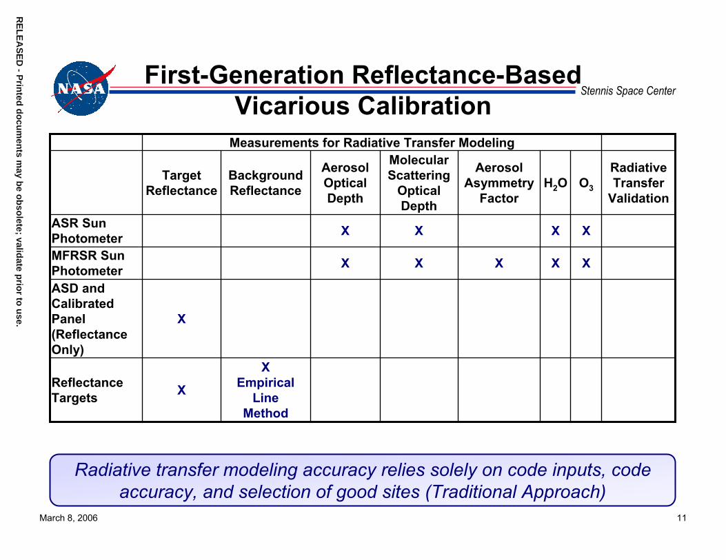
Stennis Space CenterFirst-Generation Reflectance-Based
Vicarious CalibrationMeasurements for Radiative Transfer Modeling
Target Reflectance
BackgroundReflectance
Aerosol Optical Depth
MolecularScattering
OpticalDepth
AerosolAsymmetry
FactorH2O O3
RadiativeTransfer
Validation
ASR Sun Photometer X X X X
MFRSR Sun Photometer X X X X X
ASD and Calibrated Panel (Reflectance Only)
X
Reflectance Targets X
XEmpirical
LineMethod
Radiative transfer modeling accuracy relies solely on code inputs, code accuracy, and selection of good sites (Traditional Approach)

RE
LE
AS
ED
- Prin
ted d
ocu
men
ts may b
e ob
solete; valid
ate prio
r to u
se.R
EL
EA
SE
D - P
rinted
do
cum
ents m
ay be o
bso
lete; validate p
rior to
use.
March 8, 2006 12
Stennis Space CenterSecond-generation Reflectance-based
Vicarious CalibrationMeasurements for Radiative Transfer Modeling
Target Reflectance
BackgroundReflectance
Aerosol Optical Depth
MolecularScattering
OpticalDepth
AerosolAsymmetry
FactorH2O O3
RadiativeTransfer
Validation
ASR Sun Photometer X X X X
MFRSR Sun Photometer X X X X X
Radiometrically Calibrated ASD & Calibrated Panel
X X
Reflectance Targets
XEmpirical
LineMethod
Satellite H2O & O3
X X
Radiometrically calibrated spectroradiometer panel radiance measurements allow for radiative transfer modeling validation

RE
LE
AS
ED
- Prin
ted d
ocu
men
ts may b
e ob
solete; valid
ate prio
r to u
se.R
EL
EA
SE
D - P
rinted
do
cum
ents m
ay be o
bso
lete; validate p
rior to
use.
March 8, 2006 13
Stennis Space CenterTypical Radiometric Vicarious Calibration
CHECK AND REVIEW INPUT PARAMETERS
COLLECT GROUND TRUTH
DATA
RADIOSONDE, TOMS, SENSOR-VIEWING & SOLAR GEOMETRY(P, T, H2O, O3, θV, θS)
SUN PHOTOMETER (AEROSOL PROPERTIES)
SPECTRORADIOMETER, REFERENCE AND TARGET BRDF, BACKGROUND
ALBEDO, SENSOR SPECTRAL RESPONSE
ATMOSPHERIC GASEOUS PROFILE
AEROSOL ASYMMETRY
AND VISIBILITY PROPERTIES
TARGET AND BACKGROUND REFLECTANCE
MODTRAN INPUT
MODTRAN VERIFICATIONGROUND RADIANCE ESTIMATE FOR REFERENCE PANEL COMPARED TO
CALIBRATED ASD RADIANCE
NO RADIANCE ESTIMATE AGREES WITH
GROUND MEASUREMENTS?
MODTRAN SENSOR
SPECTRAL RESPONSE
MODTRANAT-SENSOR RADIANCE
ESTIMATION
Radiative Transfer Input
Parameter Setup Software
Suite
YES
RE
LE
AS
ED
- Prin
ted d
ocu
men
ts may b
e ob
solete; valid
ate prio
r to u
se.R
EL
EA
SE
D - P
rinted
do
cum
ents m
ay be o
bso
lete; validate p
rior to
use.
March 8, 2006 14
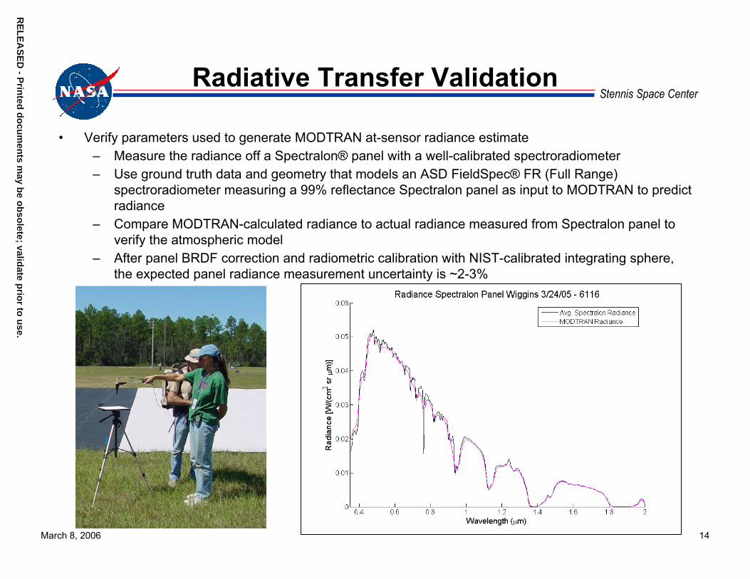
Stennis Space CenterRadiative Transfer Validation
• Verify parameters used to generate MODTRAN at-sensor radiance estimate– Measure the radiance off a Spectralon® panel with a well-calibrated spectroradiometer– Use ground truth data and geometry that models an ASD FieldSpec® FR (Full Range)
spectroradiometer measuring a 99% reflectance Spectralon panel as input to MODTRAN to predict radiance
– Compare MODTRAN-calculated radiance to actual radiance measured from Spectralon panel to verify the atmospheric model
– After panel BRDF correction and radiometric calibration with NIST-calibrated integrating sphere, the expected panel radiance measurement uncertainty is ~2-3%

RE
LE
AS
ED
- Prin
ted d
ocu
men
ts may b
e ob
solete; valid
ate prio
r to u
se.R
EL
EA
SE
D - P
rinted
do
cum
ents m
ay be o
bso
lete; validate
March 8, 2006 15
Stennis Space CenterCalibration and Characterization of ASD FieldSpec Spectroradiometers
• NASA SSC maintains four ASD FieldSpec FR spectroradiometers– Laboratory transfer radiometers– Ground surface reflectance for V&V
field collection activities• Radiometric Calibration
– NIST-calibrated integrating sphere serves as source with known spectral radiance
• Spectral Calibration– Laser and pen lamp illumination of
integrating sphere• Environmental Testing
– Temperature stability tests performed in environmental chamber
prio
r to u
se.
Environmental Chamber with ASD
RE
LE
AS
ED
- Prin
ted d
ocu
men
ts may b
e ob
solete; valid
ate prio
r to u
se.R
EL
EA
SE
D - P
rinted
do
cum
ents m
ay be o
bso
lete; validate p
rior to
use.
March 8, 2006 16
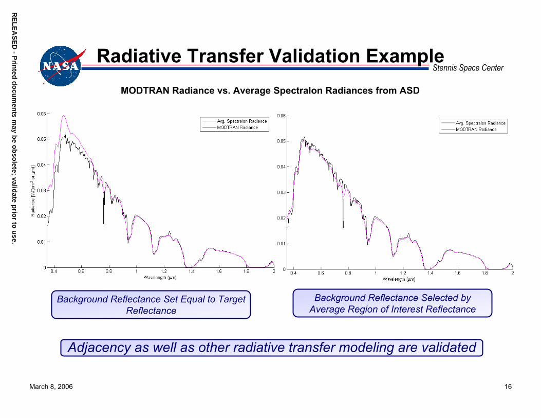
Stennis Space CenterRadiative Transfer Validation Example
MODTRAN Radiance vs. Average Spectralon Radiances from ASD
Background Reflectance Selected by Average Region of Interest Reflectance
Background Reflectance Set Equal to Target Reflectance
Adjacency as well as other radiative transfer modeling are validated
RE
LE
AS
ED
- Prin
ted d
ocu
men
ts may b
e ob
solete; valid
ate prio
r to u
se.R
EL
EA
SE
D - P
rinted
do
cum
ents m
ay be o
bso
lete; validate p
rior to
use.
March 8, 2006 17
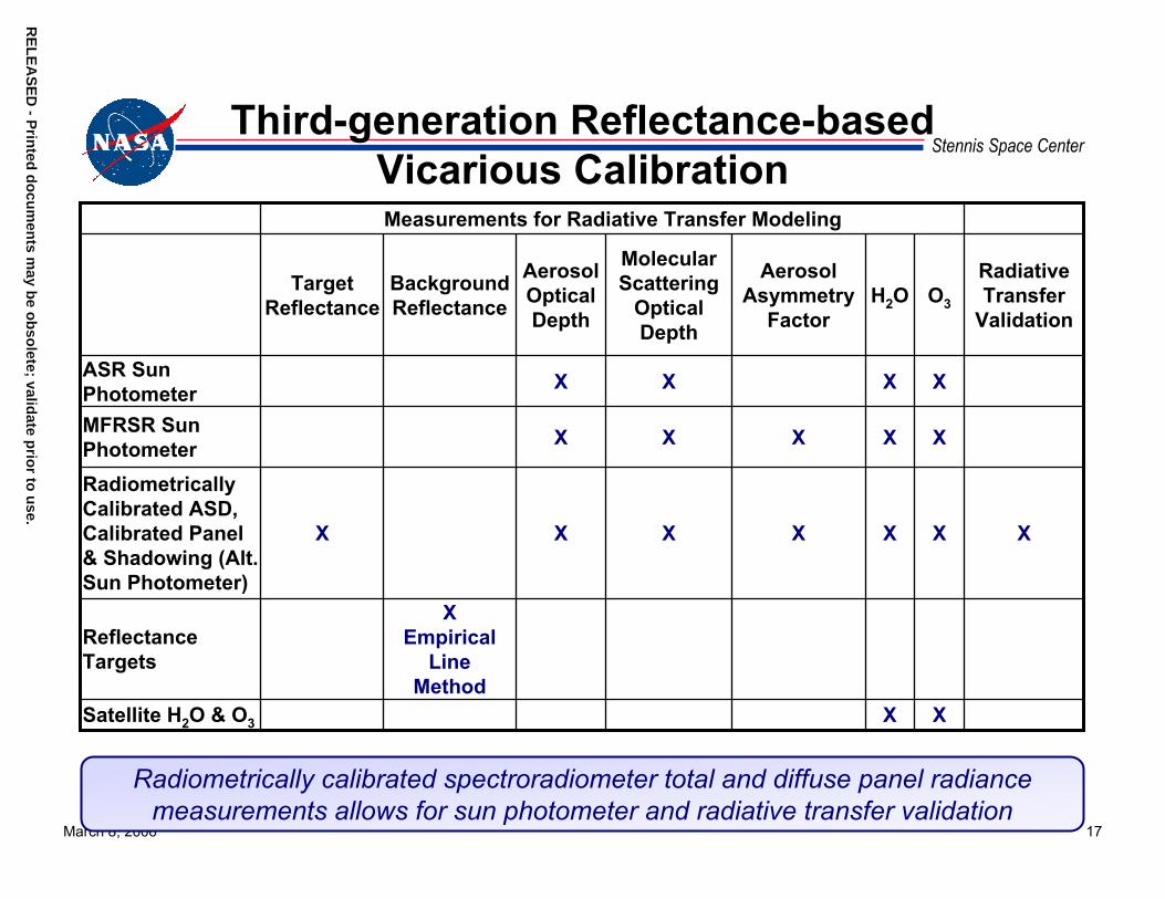
Stennis Space CenterThird-generation Reflectance-based
Vicarious CalibrationMeasurements for Radiative Transfer Modeling
Target Reflectance
BackgroundReflectance
Aerosol Optical Depth
MolecularScattering
OpticalDepth
AerosolAsymmetry
FactorH2O O3
RadiativeTransfer
Validation
ASR Sun Photometer X X X X
MFRSR Sun Photometer X X X X X
Radiometrically Calibrated ASD, Calibrated Panel & Shadowing (Alt. Sun Photometer)
X X X X X X X
Reflectance Targets
XEmpirical
LineMethod
Satellite H2O & O3 X X
Radiometrically calibrated spectroradiometer total and diffuse panel radiance measurements allows for sun photometer and radiative transfer validation
March 8, 2006 18
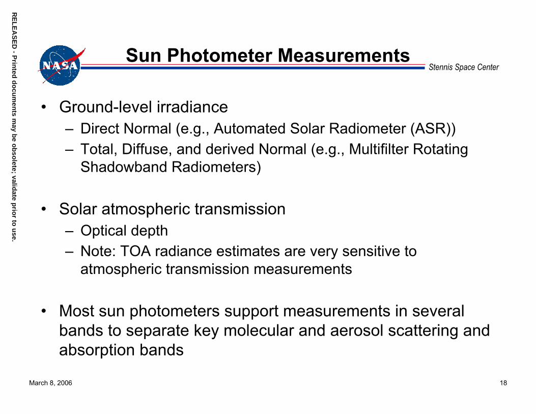
Stennis Space CenterSun Photometer Measurements
• Ground-level irradiance– Direct Normal (e.g., Automated Solar Radiometer (ASR))– Total, Diffuse, and derived Normal (e.g., Multifilter Rotating
Shadowband Radiometers)
• Solar atmospheric transmission– Optical depth– Note: TOA radiance estimates are very sensitive to
atmospheric transmission measurements
• Most sun photometers support measurements in several bands to separate key molecular and aerosol scattering and absorption bands
RE
LE
AS
ED
- Prin
ted d
ocu
men
ts may b
e ob
solete; valid
ate prio
r to u
se.R
EL
EA
SE
D - P
rinted
do
cum
ents m
ay be o
bso
lete; validate p
rior to
use.

RE
LE
AS
ED
- Prin
ted d
ocu
men
ts may b
e ob
solete; valid
ate prio
r to u
se.R
EL
EA
SE
D - P
rinted
do
cum
ents m
ay be o
bso
lete; validate p
rior to
use.
March 8, 2006 19
Stennis Space CenterTraditional Sun Photometers
University of Arizona Reagan ASR1
Multifilter Rotating Shadowband Radiometer
(MFRSR)• 10 narrow bands• 10 nm bandwidth• Direct solar irradiance
• 6 narrow bands• 10 nm bandwidth• Total and diffuse solar
irradiance1 University of Arizona, 2005. Automated Solar Radiometer. Optical Sciences Center, Remote Sensing Group: Field Equipment – Solar Radiometers.
April 25. http://www.optics.arizona.edu/rsg/menu_items/resources/fld-eq.htm (accessed March 4, 2006).

RE
LE
AS
ED
- Prin
ted d
ocu
men
ts may b
e ob
solete; valid
ate prio
r to u
se.R
EL
EA
SE
D - P
rinted
do
cum
ents m
ay be o
bso
lete; validate p
rior to
use.
March 8, 2006 20
Stennis Space CenterTraditional In-field Calibration of Sun
Photometers• Langley data points are in
instrument units that correspond to irradiance
• TOA irradiance (Vo, Eo) values for each channel are derived from extrapolation to zero airmass
• Historical Vo values are tracked over time to verify calibration stability
• TOA irradiance varies minimally throughout the year after Sun-Earth distance correction, giving a near constant for comparison

RE
LE
AS
ED
- Prin
ted d
ocu
men
ts may b
e ob
solete; valid
ate prio
r to u
se.R
EL
EA
SE
D - P
rinted
do
cum
ents m
ay be o
bso
lete; validate p
rior to
use.
March 8, 2006 21
Stennis Space CenterTraditional In-field Calibration of Sun
Photometers (cont.)• Langley plot calibration requires
many clear days with stationary atmospheres– Not practical in many
locations– 5% or more errors in
transmission are quite possible
• Built-in irradiance source or laboratory irradiance calibration could improve accuracy in areas where stationary atmospheres are difficult to achieve
RE
LE
AS
ED
- Prin
ted d
ocu
men
ts may b
e ob
solete; valid
ate prio
r to u
se.R
EL
EA
SE
D - P
rinted
do
cum
ents m
ay be o
bso
lete; validate p
rior to
use.
March 8, 2006 22
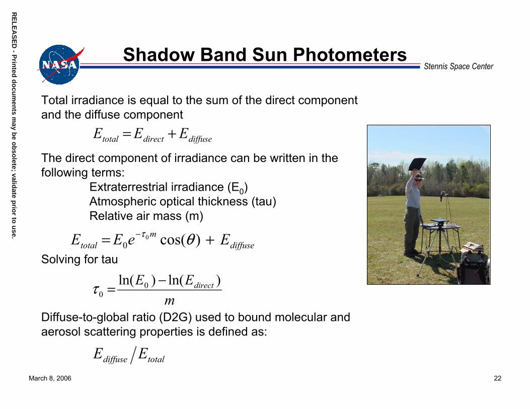
Stennis Space CenterShadow Band Sun Photometers
Total irradiance is equal to the sum of the direct component and the diffuse component
The direct component of irradiance can be written in the following terms:
Extraterrestrial irradiance (E0)Atmospheric optical thickness (tau)Relative air mass (m)
Solving for tau
Diffuse-to-global ratio (D2G) used to bound molecular and aerosol scattering properties is defined as:
diffusedirecttotal EEE +=
mEE direct )ln()ln( 0
0−=τ
totaldiffuse EE
diffusem
total EeEE += − )cos(00 θτ
RE
LE
AS
ED
- Prin
ted d
ocu
men
ts may b
e ob
solete; valid
ate prio
r to u
se.R
EL
EA
SE
D - P
rinted
do
cum
ents m
ay be o
bso
lete; validate p
rior to
use.
March 8, 2006 23
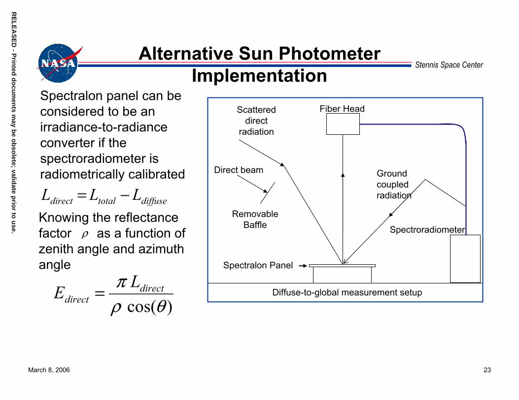
Stennis Space CenterAlternative Sun Photometer
Implementation
)cos(θρπ direct
directLE =
Spectralon panel can be considered to be an irradiance-to-radiance converter if the spectroradiometer is radiometrically calibrated
diffusetotaldirect LLL −=Knowing the reflectance factor as a function of zenith angle and azimuth angle
ρ Spectroradiometer
Spectralon Panel
Diffuse-to-global measurement setup
Ground coupled radiation
Scattered direct
radiation
Direct beam
Removable Baffle
Fiber Head
RE
LE
AS
ED
- Prin
ted d
ocu
men
ts may b
e ob
solete; valid
ate prio
r to u
se.R
EL
EA
SE
D - P
rinted
do
cum
ents m
ay be o
bso
lete; validate p
rior to
use.
March 8, 2006 24
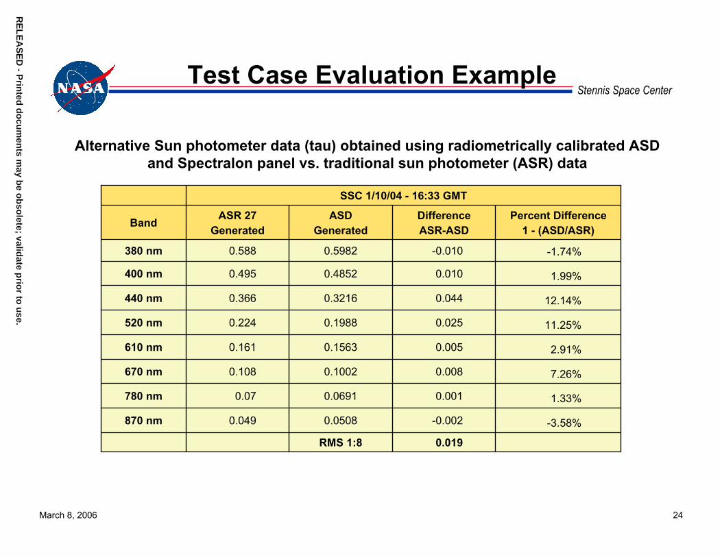
Stennis Space CenterTest Case Evaluation Example
Alternative Sun photometer data (tau) obtained using radiometrically calibrated ASD and Spectralon panel vs. traditional sun photometer (ASR) data
SSC 1/10/04 - 16:33 GMT
Band ASR 27Generated
ASDGenerated
DifferenceASR-ASD
Percent Difference1 - (ASD/ASR)
380 nm 0.588 0.5982 -0.010 -1.74%
400 nm 0.495 0.4852 0.010 1.99%
440 nm 0.366 0.3216 0.044 12.14%
520 nm 0.224 0.1988 0.025 11.25%
610 nm 0.161 0.1563 0.005 2.91%
670 nm 0.108 0.1002 0.008 7.26%
780 nm 0.07 0.0691 0.001 1.33%
870 nm 0.049 0.0508 -0.002 -3.58%
RMS 1:8 0.019
RE
LE
AS
ED
- Prin
ted d
ocu
men
ts may b
e ob
solete; valid
ate prio
r to u
se.R
EL
EA
SE
D - P
rinted
do
cum
ents m
ay be o
bso
lete; validate p
rior to
use.
March 8, 2006 25
Stennis Space Center
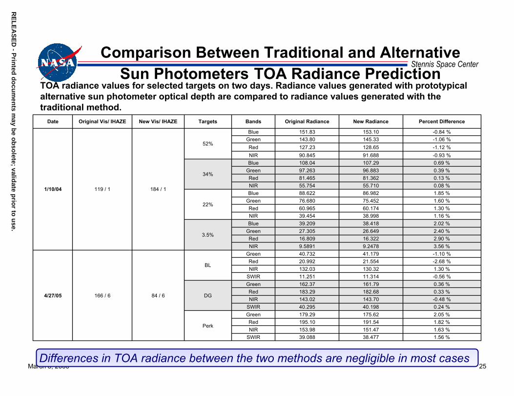
TOA radiance values for selected targets on two days. Radiance values generated with prototypical alternative sun photometer optical depth are compared to radiance values generated with the traditional method.
Comparison Between Traditional and Alternative Sun Photometers TOA Radiance Prediction
Date Original Vis/ IHAZE New Vis/ IHAZE Targets Bands Original Radiance New Radiance Percent Difference
Blue 151.83 153.10 -0.84 %Green 143.80 145.33 -1.06 %Red 127.23 128.65 -1.12 %NIR 90.845 91.688 -0.93 %Blue 108.04 107.29 0.69 %
Green 97.263 96.883 0.39 %Red 81.465 81.362 0.13 %NIR 55.754 55.710 0.08 %Blue 88.622 86.982 1.85 %
Green 76.680 75.452 1.60 %Red 60.965 60.174 1.30 %NIR 39.454 38.998 1.16 %Blue 39.209 38.418 2.02 %
Green 27.305 26.649 2.40 %Red 16.809 16.322 2.90 % NIR 9.5891 9.2478 3.56 %
Green 40.732 41.179 -1.10 %Red 20.992 21.554 -2.68 %NIR 132.03 130.32 1.30 %
SWIR 11.251 11.314 -0.56 %Green 162.37 161.79 0.36 %Red 183.29 182.68 0.33 %NIR 143.02 143.70 -0.48 %
SWIR 40.295 40.198 0.24 %Green 179.29 175.62 2.05 %Red 195.10 191.54 1.82 %NIR 153.98 151.47 1.63 %
SWIR 39.088 38.477 1.56 %
Perk
DG
BL
4/27/05 166 / 6 84 / 6
3.5%
22%
34%
52%
1/10/04 119 / 1 184 / 1
Differences in TOA radiance between the two methods are negligible in most cases

RE
LE
AS
ED
- Prin
ted d
ocu
men
ts may b
e ob
solete; valid
ate prio
r to u
se.R
EL
EA
SE
D - P
rinted
do
cum
ents m
ay be o
bso
lete; validate p
rior to
use.
March 8, 2006 26
Stennis Space CenterAlternative Sun Photometer Summary
• Differences between the alternative and traditional Sun photometer data (tau, D2G) are relatively small in most cases– Additional analysis shows that in certain cases, the prototype may
produce more accurate measurements than a traditional method in a Stennis-like environment for lack of sufficient Langley plots
– Improves confidence in all Sun photometer measurements• Utilizes existing commonly used vicarious calibration equipment
(Spectralon panel and radiometrically calibrated spectroradiometer)• The need for early deployment to catch many sunrises and sunsets can
be minimized• Current configuration takes hyperspectral measurements
– Current processing uses spectral synthesis to generate bands foreither MFRSR or ASR
• Spectroradiometer calibration critical to success– High-quality, in-field calibration could be extremely beneficial
March 8, 2006 27
Stennis Space CenterDesired In-field Radiometric
Calibration Source• Radiance level comparable to sea-level solar radiance
values off terrestrial targets over the solar reflective region• Radiometric stability equal to or better than 1%• Spectrally stable
olete;
• Capable of operating over a wide temperature range (10–40 °C)
e prio
r
• Spatially uniform light field over at least a 25 mm diameter aperture
• Capable of operating for a continuous period of 8 hours without a line source
• Single-person portable
RE
LE
AS
ED
- Prin
ted d
ocu
men
ts may b
e ob
svalid
at to
use.
RE
LE
AS
ED
- Prin
ted d
ocu
men
ts may b
e ob
solete; valid
ate prio
r to u
se.
RE
LE
AS
ED
- Prin
ted d
ocu
men
ts may b
e ob
solete; valid
ate prio
r to u
se.R
EL
EA
SE
D - P
rinted
do
cum
ents m
ay be o
bso
lete; validate p
rior to
use.
March 8, 2006 28
Stennis Space CenterTypical Laboratory Radiometric
Sources
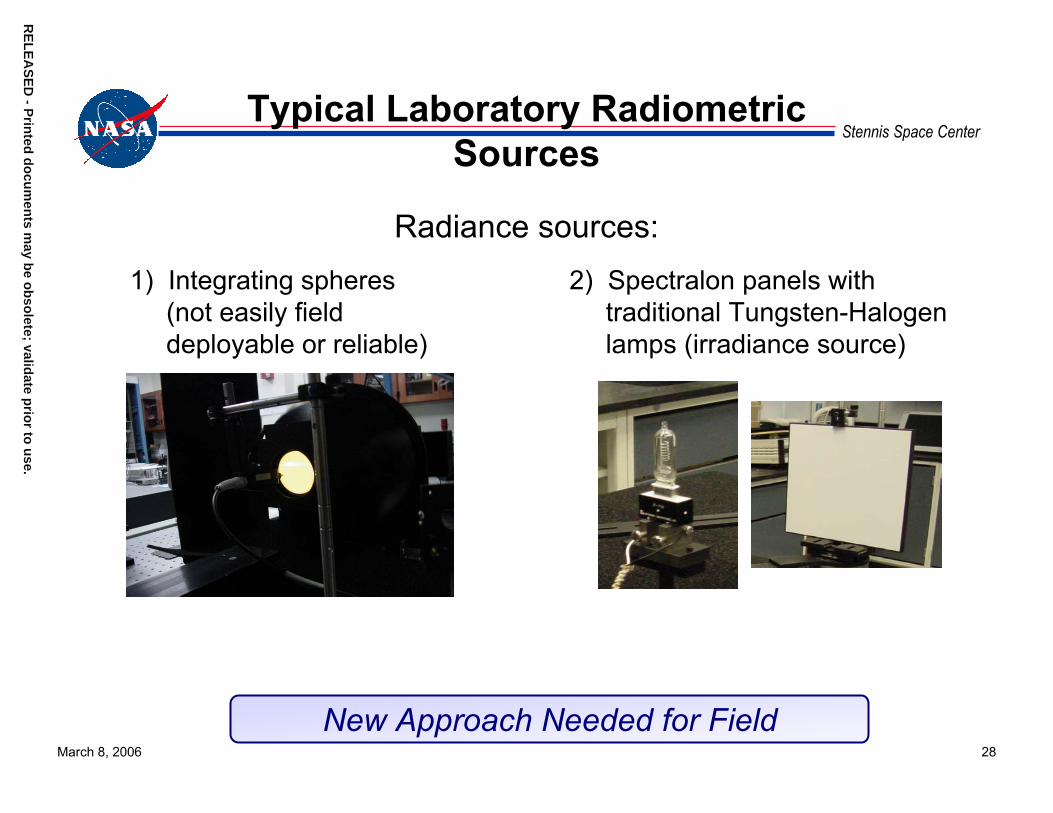
Radiance sources: 2) Spectralon panels with
traditional Tungsten-Halogen lamps (irradiance source)
1) Integrating spheres (not easily field deployable or reliable)
New Approach Needed for Field
March 8, 2006 29
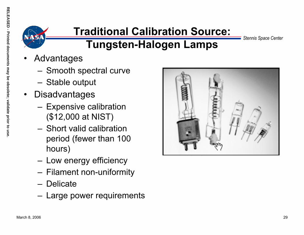
Stennis Space CenterTraditional Calibration Source:
Tungsten-Halogen Lamps• Advantages
– Smooth spectral curve– Stable output
• Disadvantages– Expensive calibration
($12,000 at NIST)– Short valid calibration
period (fewer than 100 hours)
– Low energy efficiency– Filament non-uniformity– Delicate– Large power requirements
RE
LE
AS
ED
- Prin
ted d
ocu
men
ts may b
e ob
solete; valid
ate prio
r to u
se.R
EL
EA
SE
D - P
rinted
do
cum
ents m
ay be o
bso
lete; validate p
rior to
use.

RE
LE
AS
ED
- Prin
ted d
ocu
men
ts may b
e ob
solete; valid
ate prio
r to u
se.R
EL
EA
SE
D - P
rinted
do
cum
ents m
ay be o
bso
lete; validate p
rior to
use.
March 8, 2006 30
Stennis Space CenterNew Calibration Approach:
High-Intensity LEDs • Advantages
– Extreme long life 50–100 thousands of hours to 50% of initial output
– Inexpensive– Reduced maintenance costs– Energy efficient– Small footprint– Solid state (no filament to break)– No heat or UV in light beam– Low voltage DC operation
• Disadvantages– Narrow spectrum (white phosphors
help; sometimes an advantage)
March 8, 2006 31
Stennis Space CenterLED-based Approach
• Exploit recent developments in high-power LED sources• Utilize integrating sphere to create uniform light field
s may
• Use light-stabilization control to achieve radiometric stability• Test and characterize system with environmental chamber
and independent spectroradiometer
RE
LE
AS
ED
- Prin
ted d
ocu
men
tb
e ob
solete; valid
ate prio
r to u
se.R
EL
EA
SE
D - P
rinted
do
cum
ents m
ay be o
bso
lete; validate p
rior to
use.
RE
LE
AS
ED
- Prin
ted d
ocu
men
ts may b
e ob
solete; valid
ate prio
r to u
se.R
EL
EA
SE
D - P
rinted
do
cum
ents m
ay be o
bso
lete; validate p
rior to
use.
March 8, 2006 32
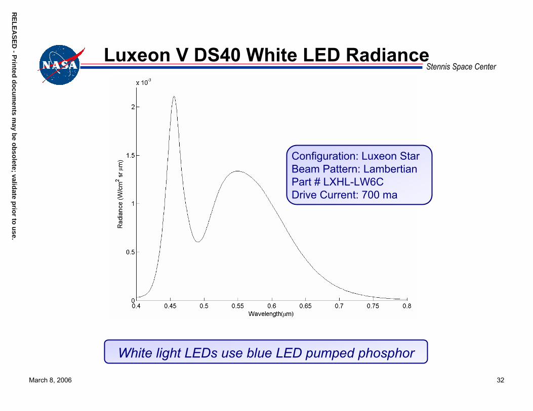
Stennis Space CenterLuxeon V DS40 White LED Radiance
Configuration: Luxeon StarBeam Pattern: LambertianPart # LXHL-LW6CDrive Current: 700 ma
White light LEDs use blue LED pumped phosphor
RE
LE
AS
ED
- Prin
ted d
ocu
men
ts may b
e ob
solete; valid
ate prio
r to u
se.R
EL
EA
SE
D - P
rinted
do
cum
ents m
ay be o
bso
lete; validate p
rior to
use.
March 8, 2006 33
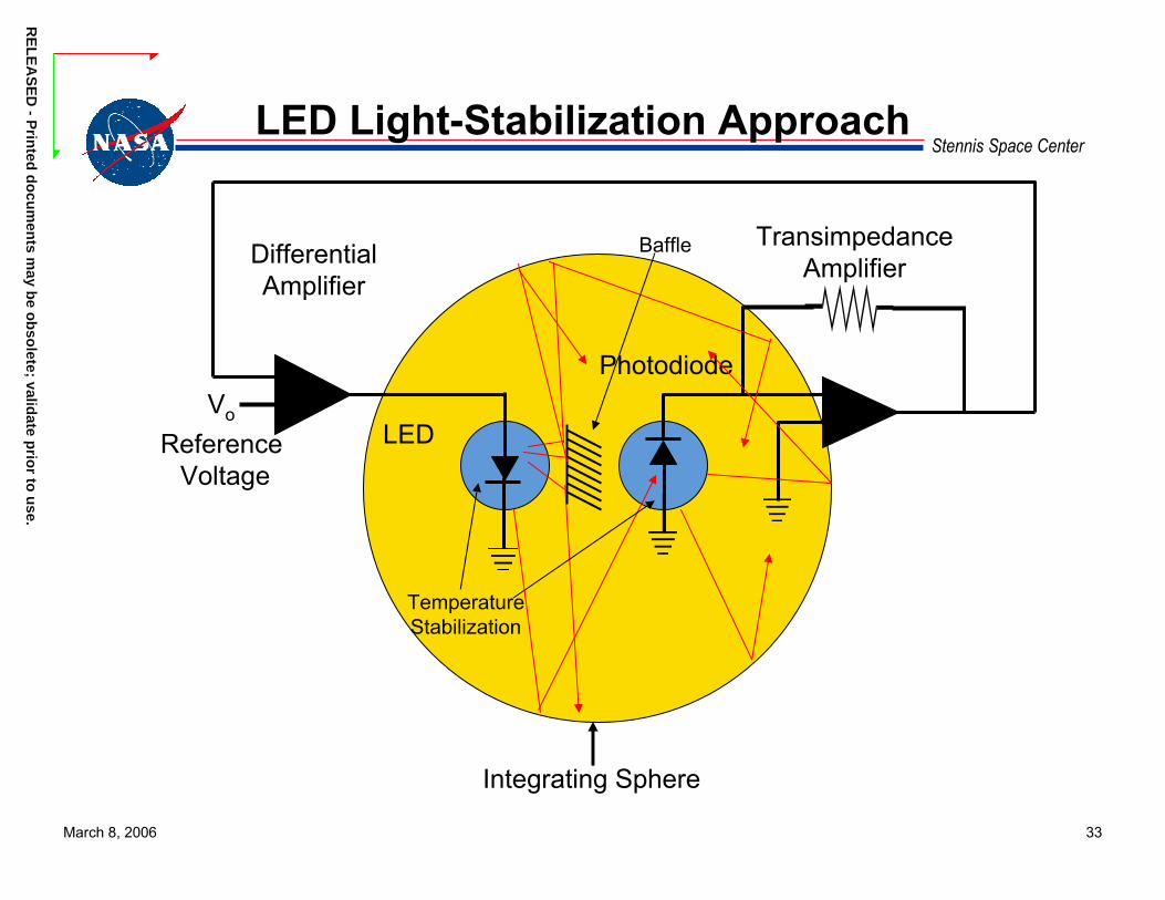
Stennis Space CenterLED Light-Stabilization Approach
Integrating Sphere
Reference Voltage
Vo
TransimpedanceAmplifierDifferential
Amplifier
LED
Photodiode
TemperatureStabilization
Baffle

RE
LE
AS
ED
- Prin
ted d
ocu
men
ts may b
e ob
solete; valid
ate prio
r to u
se.R
EL
EA
SE
D - P
rinted
do
cum
ents m
ay be o
bso
lete; validate p
rior to
use.
March 8, 2006 34
Stennis Space CenterLED-based Radiance Source
• Temperature-stabilized white light LED– Spectral range: 420–750 nm– Other LEDs would increase the
spectral range• Temperature-stabilized
photodiode and feedback loop stabilize integrating sphere radiance level
• Daily lab drift <0.2%• Short term drift <0.5% over
temperature range 10–40 °C and over large spectral range
LED illuminated integrating sphere radiometric calibration source with photodiode stabilization

RE
LE
AS
ED
- Prin
ted d
ocu
men
ts may b
e ob
solete; valid
ate prio
r to u
se.R
EL
EA
SE
D - P
rinted
do
cum
ents m
ay be o
bso
lete; validate p
rior to
use.
March 8, 2006 35
Stennis Space Center
400 450 500 550 600 650 700 7500
0.1
0.2
0.3
0.4
0.5
0.6
0.7
λ (nm)
L (W
/m2 ·n
m·s
r)
Spectral Response
White 5W LED;I = 700ma12" Sphere; ASD Lmax
Spectralon PanelMODTRAN ρ=.3 ρbkg = 1
White light LED source in 8” diameter sphere produces radiance levels comparable to brightly illuminated scenes in the visible
Comparison of LED Integrating Sphere With Traditional Sources
• MODTRAN calculations for 30°solar zenith, mid-latitude summer atmosphere, 23 km visibility and rural aerosol
• TOA radiance levels calculated for 30% reflectance targets and 1 m above a Spectralon panel
• 12” sphere data for 3200 K tungsten lamp
RE
LE
AS
ED
- Prin
ted d
ocu
men
ts may b
e ob
solete; valid
ate prio
r to u
se.R
EL
EA
SE
D - P
rinted
do
cum
ents m
ay be o
bso
lete; validate p
rior to
use.
March 8, 2006 36
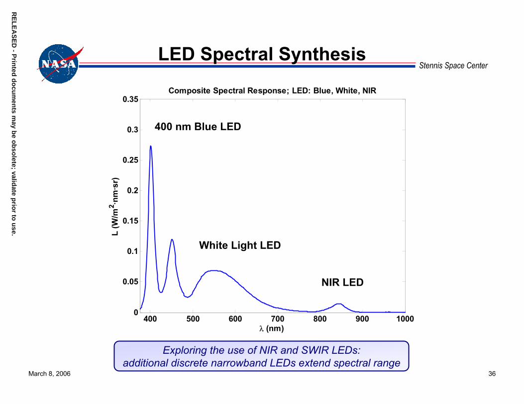
Stennis Space CenterLED Spectral Synthesis
400 500 600 700 800 900 10000
0.05
0.1
0.15
0.2
0.25
0.3
0.35
λ (nm)
L (W
/m2 ·n
m·s
r)
Composite Spectral Response; LED: Blue, White, NIR
400 nm Blue LED
White Light LED
NIR LED
Exploring the use of NIR and SWIR LEDs: additional discrete narrowband LEDs extend spectral range
March 8, 2006 37
Stennis Space CenterSummary and Comments
• Autonomous Visible to SWIR ground-based vicarious Cal/Val will be an essential Cal/Val component with such a large number of systems
• Radiometrically calibrated spectroradiometers can improve confidence in current ground truth data – Validation of radiometric modeling – Validation or replacement of traditional Sun photometer
measurements– Should enable significant reduction and operation of deployed
equipment, such as equipment used in traditional Sun photometer approaches
RE
LE
AS
ED
- Prin
ted d
ocu
men
ts may b
e ob
solete; valid
ate prio
r to u
se.R
EL
EA
SE
D - P
rinted
do
cum
ents m
ay be o
bso
lete; validate p
rior to
use.

March 8, 2006 38
Stennis Space CenterSummary and Comments (cont.)
• Simple field-portable white light LED calibration source shows promise for visible range (420–750 nm)– Prototype demonstrated <0.5% drift over 10-40 °C
temperature range– Additional complexity (more LEDs) will be necessary for
extending spectral range into the NIR and SWIR– LED long lifetimes should produce at least several hundreds of
hours or more stability, minimizing need for expensive calibrations and supporting long-duration field campaigns
– Enabling technology for developing autonomous sites
RE
LE
AS
ED
- Prin
ted d
ocu
men
ts may b
e ob
solete; valid
ate prio
r to u
se.R
EL
EA
SE
D - P
rinted
do
cum
ents m
ay be o
bso
lete; validate p
rior to
use.

RE
LE
AS
ED
- Prin
ted d
ocu
men
ts may b
e ob
solete; valid
ate prio
r to u
se.R
EL
EA
SE
D - P
rinted
do
cum
ents m
ay be o
bso
lete; validate p
rior to
use.
March 8, 2006 39
Stennis Space CenterTechnical Points of Contact
Robert E. [email protected]
Mary A. [email protected]
Thomas StanleyNASA [email protected]
Participation in this work by Science Systems and Applications, Inc., was supported by NASA at the John C. Stennis Space Center, Mississippi,under Task Order NNS04AB54T.