Release Indigo MoveIt Motion Planning Framework · MoveIt, Release Indigo 5.The robot moves its...
33
MoveIt Release Indigo MoveIt Motion Planning Framework August 10, 2016
Transcript of Release Indigo MoveIt Motion Planning Framework · MoveIt, Release Indigo 5.The robot moves its...

MoveItRelease Indigo
MoveIt Motion Planning Framework
August 10, 2016


Contents
1 Beginner Tutorials 1
2 Advanced Tutorials 13
3 Configuration Tutorials 23
i

ii

CHAPTER 1
Beginner Tutorials
1.1 Move Group Interface/C++ API
In MoveIt!, the primary user interface is through the :move_group_interface:‘MoveGroup‘ class. It provides easy touse functionality for most operations that a user may want to carry out, specifically setting joint or pose goals, creatingmotion plans, moving the robot, adding objects into the environment and attaching/detaching objects from the robot.
1.1.1 The entire code
The entire code can be seen :codedir:‘here in the moveit_pr2 github project<planning>‘.
1.1.2 Compiling the code
Follow the instructions for compiling code from source.
1.1.3 The launch file
The entire launch file is here on github. All the code in this tutorial can be compiled and run from thepr2_moveit_tutorials package that you have as part of your MoveIt! setup.
1.1.4 Running the code
Roslaunch the launch file to run the code directly from pr2_moveit_tutorials:
roslaunch pr2_moveit_tutorials move_group_interface_tutorial.launch
1.1.5 Expected Output
In Rviz, we should be able to see the following (there will be a delay of 5-10 seconds between each step):
1. The robot moves its right arm to the pose goal to its right front.
2. The robot repeats the same motion from 1.
3. The robot moves its right arm to the joint goal at its right side.
4. The robot moves its right arm back to a new pose goal while maintaining the end-effector level.
1

MoveIt, Release Indigo
5. The robot moves its right arm along the desired cartesian path (a triangle up+forward, left, down+back).
6. A box object is added into the environment to the right of the right arm.
7. The robot moves its right arm to the pose goal, avoiding collision with the box.
8. The object is attached to the wrist (its color will change to purple/orange/green).
9. The object is detached from the wrist (its color will change back to green).
10. The object is removed from the environment.
1.2 Move Group Interface/Python API
In MoveIt!, the primary user interface is through the RobotCommander class. It provides functionality for mostoperations that a user may want to carry out, specifically setting joint or pose goals, creating motion plans, moving therobot, adding objects into the environment and attaching/detaching objects from the robot.
1.2.1 The entire code
The entire code can be seen :codedir:‘here in the moveit_pr2 githubproject<planning/scripts/move_group_python_interface_tutorial.py>‘.
1.2.2 The launch file
The entire launch file is here on github. All the code in this tutorial can be run from the pr2_moveit_tutorials packagethat you have as part of your MoveIt! setup.
Running the code ——————–^
Roslaunch the launch file to run the code directly from pr2_moveit_tutorials:
roslaunch pr2_moveit_tutorials move_group_python_interface_tutorial.launch
1.2.3 Expected Output
In Rviz, we should be able to see the following (there will be a delay of 5-10 seconds between each step):
1. The robot moves its left arm to the pose goal in front of it (plan1)
2. The robot again moves its left arm to the same goal (plan1 again)
3. The robot moves its left arm to the joint goal to the side,
4. The robot moves its left arm along the desired cartesian path.
1.3 Setup Assistant Tutorial
1.3.1 Overview
The MoveIt! Setup Assistant is a graphical user interface for configuring any robot for use with MoveIt!. Its primaryfunction is generating a Semantic Robot Description Format (SRDF) file for your robot. Additionally, it generatesother necessary configuration files for use with the MoveIt! pipeline. To learn more about the SRDF, you can gothrough the SRDF Overview page.
2 Chapter 1. Beginner Tutorials

MoveIt, Release Indigo
1.3.2 Pre-requisites
MoveIt! and ROS
• Follow the instructions for :moveit_website:‘installing MoveIt!<install>‘ first if you have not already donethat.
1.3.3 STEP 1: Start
• To start the MoveIt! Setup Assistant:
roslaunch moveit_setup_assistant setup_assistant.launch
• This will bringup the start screen with two choices: Create New MoveIt! Configuration Package or Edit ExistingMoveIt! Configuration Package.
• Click on the Create New MoveIt! Configuration Package button to bring up the following screen:
setup_assistant_start.png
• Click on the browse button and navigate to the pr2.urdf.xacro file installed when you installed ros-hydro-moveit-full-pr2. (This file gets installed in /opt/ros/hydro/share/pr2_description/robots/pr2.urdf.xacro on Ubuntu withROS Hydro.) Choose that file and then click Load Files. The Setup Assistant will load the files (this might takea few seconds) and present you with this screen:
setup_assistant_pr2_100.png
1.3.4 STEP 2: Generate Self-Collision Matrix
The Default Self-Collision Matrix Generator searches for pairs of links on the robot that can safely be disabled fromcollision checking, decreasing motion planning processing time. These pairs of links are disabled when they arealways in collision, never in collision, in collision in the robot’s default position or when the links are adjacent toeach other on the kinematic chain. The sampling density specifies how many random robot positions to check for selfcollision. Higher densities require more computation time while lower densities have a higher possibility of disablingpairs that should not be disabled. The default value is 10,000 collision checks. Collision checking is done in parallelto decrease processing time.
• Click on the Self-Collisions pane selector on the left-hand side and click on the Regenerate Default CollisionMatrix button. The Setup Assistant will work for a few second before presenting you the results of its computa-tion in the main table.
1.3. Setup Assistant Tutorial 3

MoveIt, Release Indigo
setup_assistant_pr2_self_collisions.png→ setup_assistant_pr2_self_collisions_done.png
1.3.5 STEP 3: Add Virtual Joints
Virtual joints are used primarily to attach the robot to the world. For the PR2 we will define only one virtual jointattaching the base_footprint of the PR2 to the odom_combined world frame. This virtual joint represents the motionof the base of the robot in a plane.
• Click on the Virtual Joints pane selector. Click on Add Virtual Joint
• Set the joint name as “virtual_joint”
• Set the child link as “base_footprint” and the parent frame name as “odom_combined”.
• Set the Joint Type as “planar”.
• Click Save and you should see this screen:
setup_assistant_pr2_virtual_joints.png
1.3.6 STEP 4: Add Planning Groups
Planning groups are used for semantically describing different parts of your robot, such as defining what an arm is, oran end effector.
• Click on the Planning Groups pane selector.
• Click on Add Group and you should see the following screen:
setup_assistant_pr2_planning_groups.png
Add the right arm
• We will first add the PR2 right arm as a planning group
– Enter Group Name as right_arm
– Choose kdl_kinematics_plugin/KDLKinematicsPlugin as the kinematics solver. Note: ifyou have a custom robot and would like a powerful custom IK solver, see ‘Kinemat-ics/IKFast<http://moveit.ros.org/wiki/Kinematics/IKFast>‘_
– Let Kin. Search Resolution and Kin. Search Timeout stay at their default values.
4 Chapter 1. Beginner Tutorials

MoveIt, Release Indigo
setup_assistant_pr2_right_arm.png
• Now, click on the Save and Add Joints button. You will see a list of joints on the left hand side. You need tochoose all the joints that belong to the right arm and add them to the right hand side. The joints are arranged inthe order that they are stored in an internal tree structure. This makes it easy to select a serial chain of joints.
– Click on r_shoulder_pan_joint, hold down the Shift button on your keyboard and then click on ther_wrist_roll_joint. Now click on the > button to add these joints into the list of selected joints on the right.
setup_assistant_pr2_right_arm_joints.png
• Click Save to save the selected group. Note that each arm of the PR2 has only 7 joints and yet we added 9joints here. Some of the joints (r_upper_arm_joint and r_forearm_joint) are Fixed joints and will not be usedfor planning or kinematics.
setup_assistant_pr2_right_arm_joints_saved.png
Add the left arm
Now, add the left arm in a similar manner choosing the joints from the l_shoulder_pan_joint to the l_wrist_roll_joint.
Add the grippers
• We will also add two groups for the right and left end effectors. NOTE that you will do this using a differentprocedure than adding the arms.
– Click on the Add Group button.
– Enter Group Name as right_gripper
– Let Kin. Search Resolution and Kin. Search Timeout stay at their default values.
– Click on the Save and Add Links button.
– Choose all links that start with right_gripper and add them to the list of Selected Links on the right handside.
– Click Save
– Repeat the same procedure for the left arm of the PR2, choosing links that start with left_gripper insteadof right_gripper this time.
1.3. Setup Assistant Tutorial 5

MoveIt, Release Indigo
setup_assistant_pr2_planning_groups_grippers.png
1.3.7 STEP 5: Add Robot Poses
The Setup Assistant allows you to add certain fixed poses into the configuration. This helps if, for example, you wantto define a certain position of the robot as a Home position.
• Click on the Robot Poses pane.
• Click Add Pose. Choose a name for the pose. The robot will be in its Default position where the joint valuesare set to the mid-range of the allowed joint value range. Move the individual joints around until you are happyand then Save the pose. Note how poses are associated with particular groups. You can save individual posesfor each group.
• IMPORTANT TIP: Try to move all the joints around. If there is something wrong with the joint limits in yourURDF, you should be able to see it immediately here.
setup_assistant_pr2_saved_poses.png
1.3.8 STEP 6: Label End Effectors
We have already added the right and left grippers of the PR2. Now, we will designate these two groups as specialgroups: end-effectors. Designating these groups as end effector allows some special operations to happen on theminternally.
• Click on the End Effectors pane.
• Click Add End-Effectors.
• Choose right_eef as the End Effector Name for the right gripper.
• Select right_gripper as the End Effector Group.
• Select r_wrist_roll_link as the Parent Link for this end-effector.
• Leave Parent Group blank.
setup_assistant_pr2_end_effectors_add.png
• Click Save.
• Add the left_eef in a similar manner.
6 Chapter 1. Beginner Tutorials

MoveIt, Release Indigo
1.3.9 STEP 7: Add Passive Joints
The passive joints tab is meant to allow specification of any passive joints that might exist in a robot. This tells theplanners that they cannot (kinematically) plan for these joints. Examples of passive joints include passive casters. ThePR2 does not have any passive joints so we will skip this step.
1.3.10 STEP 8: Generate Configuration Files
You are almost there. One last step - generating all the configuration files that you will need to start using MoveIt!
• Click on the Configuration Files pane. Choose a location and name for the ROS package that will be generatedcontaining your new set of configuration files (e.g. click browse, select a good location (e.g. your home dir),click Create New Folder, enter “pr2_moveit_generated”, and click Choose. “pr2_moveit_generated” is thelocation used in the rest of the documentation on this wiki). This does not have to be within your ROS packagepath. All generated files will go directly into the directory you have chosen.
• Click on the Generate Package button. The Setup Assistant will now generate and write a set of launch andconfig files into the directory of your choosing. All the generated files will appear in the Generated Files/Folderstab and you can click on each of them for a description of what they contain.
setup_assistant_pr2_done.png
• Congratulations!! - You are now done generating the configuration files you need for MoveIt!
1.3.11 What’s Next
The MoveIt! Rviz plugin
• Start looking at how you can use the generated configuration files to play with MoveIt! using the MoveIt! RvizPlugin.
Setup IKFast Inverse Kinematics Solver
• A faster IK solver than the default KDL solver, but takes some additional steps to setup: Kinematics/IKFast
1.3.12 Additional Reading
The SRDF
• See the SRDF page for more details on the components of the SRDF mentioned in this tutorial.
URDF
• The URDF is the native robot description format in ROS and allows you to describe the kinematics, inertial,visual and sensing properties of your robot. Read through the URDF specific documentation to see how theURDF is used with MoveIt!
1.3. Setup Assistant Tutorial 7

MoveIt, Release Indigo
1.4 MoveIt! RViz Plugin Tutorial
MoveIt! comes with a plugin for the ROS Visualizer (RViz). The plugin allows you to setup scenes in which the robotwill work, generate plans, visualize the output and interact directly with a visualized robot. We will explore the pluginin this tutorial.
1.4.1 Pre-requisites
You should have completed the MoveIt! Setup Assistant tutorial and you should now have a MoveIt! configura-tion for the PR2 that you can use. This tutorial assumes the generated MoveIt! configuration package is called“pr2_moveit_config”.
Alternately, you can just install the pre-made MoveIt! configuration for the PR2 in the pr2_moveit_config ROSpackage. To install it, run:
sudo apt-get install ros-hydro-moveit-pr2
This tutorial does not require you to actually have a PR2 robot, it just needs a set of working robot model files.
1.4.2 STEP 1: Launch the demo and Configure the Plugin
• Launch the demo:
roslaunch pr2_moveit_config demo.launch
• If you are doing this for the first time, you will have to add the Motion Planning Plugin.
– In the Rviz Displays Tab, press Add
– From the moveit_ros_visualization folder, choose “MotionPlanning” as the DisplayType. Press “Ok”.
rviz_plugin_motion_planning_add.png
• In the “Global Options” tab of the “Displays” subwindow, set the Fixed Frame field to “/odom_combined”
• Now, you can start configuring the Plugin for your robot (the PR2 in this case). Click on “MotionPlanning” in“Displays”.
– Make sure the Robot Description field is set to “robot_description”
– Make sure the Planning Scene Topic field is set to “planning_scene”.
– In Planning Request, change the Planning Group to “right_arm”.
– Set the Trajectory Topic in the Planned Path tab to “/move_group/display_planned_path”.
rviz_plugin_start.png
8 Chapter 1. Beginner Tutorials

MoveIt, Release Indigo
1.4.3 STEP 2: Play with the visualized robots
There are four different visualizations active here currently:
1. The start state for motion planning (the planned group is represented in green).
2. The goal state for motion planning (the planned group is represented in orange).
3. The robot’s configuration in the planning scene/ planning environment
4. The planned path for the robot,
The display states for each of these visualizations can be toggled on and off using checkboxes.
1. The start state using the “Query Start State” checkbox in the “Planning Request” tab.
2. The goal state using the “Query Goal State” checkbox in the “Planning Request” tab.
3. The planning scene robot using the “Show Scene Robot” checkbox in the “Scene Robot” tab.
4. The planned path using the “Show Robot Visual” checkbox in the “Planned Path” tab.
rviz_plugin_visualize_robots.png
• Play with all these checkboxes to switch on and off different visualizations.
1.4.4 STEP 3: Interact with the PR2
• Press Interact in the top menu of rviz. You should see a couple of interactive markers appear for the right armof the PR2.
– One marker (corresponding to the orange colored right arm) will be used to set the “Goal State” for motionplanning. Another marker corresponding to a green colored representation of the right arm will be used toset the “Start State” for motion planning.
– You will be able to use these markers (which are attached to the tip link of each arm) to drag the armaround and change its orientation.
rviz_plugin_interact.png
1.4.5 Moving into collision
Note what happens when you try to move one of the arms into collision with the other. The two links that are incollision will turn red.
1.4. MoveIt! RViz Plugin Tutorial 9

MoveIt, Release Indigo
rviz_plugin_collision.png
The “Use Collision-Aware IK” checkbox allows you to toggle the behavior of the IK solver. When the checkbox isticked, the solver will keep attempting to find a collision-free solution for the desired end-effector pose. When it isunticked, the solver will allow collisions to happen in the solution. The links in collision will always still be visualizedin red, regardless of the state of the checkbox.
rviz_plugin_collision_aware_ik_checkbox.png
1.4.6 Moving out of reachable workspace
Note also what happens when you try to move an end-effector out of its reachable workspace (sometimes the accessdenied sign will not appear).
rviz_plugin_invalid.png
1.4.7 STEP 4: Use Motion Planning with the PR2
• Now, you can start motion planning with the PR2 in the MoveIt! Rviz Plugin.
– Move the Start State to a desired location.
– Move the Goal State to another desired location.
– Make sure both states are not in collision with the robot itself.
– Make sure the Planned Path is being visualized. Also check the “Show Trail” checkbox in the PlannedPath tab.
• In the Planning tab (at the bottom), press the Plan button. You should be able to see a visualization of the armmoving and a trail.
rviz_plugin_planned_path.png
10 Chapter 1. Beginner Tutorials

MoveIt, Release Indigo
1.4.8 What’s Next
• MoveIt! and a simulated robot - You can now start using MoveIt! with a simulated robot in Gazebo.
1.4. MoveIt! RViz Plugin Tutorial 11

MoveIt, Release Indigo
12 Chapter 1. Beginner Tutorials

CHAPTER 2
Advanced Tutorials
2.1 Kinematics/C++ API
In this section, we will walk you through the C++ API for using kinematics.
2.1.1 The RobotModel and RobotState classes
The :moveit_core:‘RobotModel‘ and :moveit_core:‘RobotState‘ classes are the core classes that give you access tothe kinematics. In this example, we will walk through the process of using the classes for the right arm of the PR2.
The entire code
The entire code can be seen :codedir:‘here in the moveit_pr2 github project<kinematics>‘.
Compiling the code
Follow the instructions for compiling code from source.
The launch file
To run the code, you will need a launch file that does two things:
• Uploads the PR2 URDF and SRDF onto the param server, and
• Puts the kinematics_solver configuration generated by the MoveIt! Setup Assistant onto the ROS parame-ter server in the namespace of the node that instantiates the classes in this tutorial.
All the code in this tutorial can be compiled and run from the pr2_moveit_tutorials package that you have as part ofyour MoveIt! setup.
Running the code
Roslaunch the launch file to run the code directly from pr2_moveit_tutorials:
roslaunch pr2_moveit_tutorials kinematic_model_tutorial.launch
13

MoveIt, Release Indigo
Expected Output
The expected output will be in the following form. The numbers will not match since we are using random jointvalues:
[ INFO] [1384819451.749126980]: Model frame: /odom_combined[ INFO] [1384819451.749228320]: Joint r_shoulder_pan_joint: 0.000000[ INFO] [1384819451.749268059]: Joint r_shoulder_lift_joint: 0.000000[ INFO] [1384819451.749298929]: Joint r_upper_arm_roll_joint: 0.000000[ INFO] [1384819451.749337412]: Joint r_upper_arm_joint: -1.135650[ INFO] [1384819451.749376593]: Joint r_elbow_flex_joint: 0.000000[ INFO] [1384819451.749404669]: Joint r_forearm_roll_joint: -1.050000[ INFO] [1384819451.749480167]: Joint r_forearm_joint: 0.000000[ INFO] [1384819451.749545399]: Joint r_wrist_flex_joint: 0.000000[ INFO] [1384819451.749577945]: Joint r_wrist_roll_joint: 0.000000[ INFO] [1384819451.749660707]: Current state is not valid[ INFO] [1384819451.749723425]: Current state is valid[ INFO] [1384819451.750553768]: Translation: 0.0464629-0.6603721.08426[ INFO] [1384819451.750715730]: Rotation: -0.0900434 -0.945724 -0.312248
-0.91467 -0.0455189 0.40163-0.394045 0.321768 -0.860926
[ INFO] [1384819451.751673044]: Joint r_shoulder_pan_joint: -1.306166[ INFO] [1384819451.751729266]: Joint r_shoulder_lift_joint: 0.502776[ INFO] [1384819451.751791355]: Joint r_upper_arm_roll_joint: 0.103366[ INFO] [1384819451.751853793]: Joint r_upper_arm_joint: -1.975539[ INFO] [1384819451.751907012]: Joint r_elbow_flex_joint: 2.805000[ INFO] [1384819451.751963863]: Joint r_forearm_roll_joint: -1.851939[ INFO] [1384819451.752015895]: Joint r_forearm_joint: -0.414720[ INFO] [1384819451.752064923]: Joint r_wrist_flex_joint: 0.000000[ INFO] [1384819451.752117933]: Joint r_wrist_roll_joint: 0.000000[ INFO] [1384819451.753252155]: Jacobian: 0.472372 0.0327816 -0.28711 0.0708816 1.38778e-17 0 0
0.0964629 -0.120972 -0.0626032 -0.311436 0 0 00 -0.381159 -0.0266776 -0.0320097 8.67362e-19 0 00 0.965189 0.229185 0.973042 -0.0665617 -0.991369 -0.09004340 0.261552 -0.845745 0.212168 -0.116995 0.12017 -0.914671 0 -0.48186 0.0904127 0.990899 -0.0524048 -0.394045
Additional Reading
• RobotState Display - Visualization of the RobotState using Rviz
2.2 IKFast Plugin
In this section, we will walk through configuring an IKFast plugin for MoveIt!
2.2.1 What is IKFast?
From Wikipedia: IKFast, the Robot Kinematics Compiler, is a powerful inverse kinematics solver provided withinRosen Diankov’s OpenRAVE motion planning software. Unlike most inverse kinematics solvers, IKFast can analyti-cally solve the kinematics equations of any complex kinematics chain, and generate language-specific files (like C++)for later use. The end result is extremely stable solutions that can run as fast as 5 microseconds on recent processors
14 Chapter 2. Advanced Tutorials

MoveIt, Release Indigo
2.2.2 MoveIt! IKFast
MoveIt! IKFast is a tool that generates a IKFast kinematics plugin for MoveIt using OpenRave generated cpp files.This tutorial will step you through setting up your robot to utilize the power of IKFast. MoveIt! IKFast is tested onROS Groovy with Catkin using OpenRave 0.8 with a 6dof and 7dof robot arm manipulator. While it works in theory,currently the IKFast plugin generator tool does not work with >7 degree of freedom arms.
2.2.3 Pre-requisites
You should have already created a MoveIt! configuration package for your robot, by using the Setup Assistant.
2.2.4 MoveIt! IKFast Installation
Install the MoveIt! IKFast package either from debs or from source.
Binary Install
sudo apt-get install ros-indigo-moveit-ikfast
Source
Inside your catkin workspace
git clone https://github.com/ros-planning/moveit_ikfast.git
2.2.5 OpenRAVE Installation
OpenRave is available for Ubuntu using these commands:
sudo add-apt-repository ppa:openrave/releasesudo apt-get updatesudo apt-get install openrave0.8-dp-ikfast
More detailed and updated instructions are available at OpenRave.org.
Note: You may need to use this hack reported by MoveIt! users:
Edit /usr/lib/python2.7/dist-packages/openravepy/__init__.py to add the following line just after the copyright:
__openravepy_version__ = "0.8"
Note: Use ‘’openrave0.8” instead of ‘’openrave” in the following tutorial if installed from packages
Please report your results with this on the moveit-users mailing list.
2.2.6 Create Collada File For Use With OpenRave
First you will need robot description file that is in Collada or OpenRave robot format.
If your robot is not in this format we recommend you create a ROS URDF file, then convert it to a Collada .dae fileusing the following command:
rosrun collada_urdf urdf_to_collada <myrobot_name>.urdf <myrobot_name>.dae
2.2. IKFast Plugin 15

MoveIt, Release Indigo
where <myrobot_name> is the name of your robot.
Often floating point issues arrise in converting a URDF file to Collada file, so a script has been created to round all thenumbers down to x decimal places in your .dae file. Its probably best if you skip this step initially and see if IKFastcan generate a solution with your default values, but if the generator takes longer than, say, an hour, try the following:
rosrun moveit_ikfast round_collada_numbers.py <input_dae> <output_dae> <decimal places>
From experience we recommend 5 decimal places, but if the OpenRave ikfast generator takes to long to find a solution,lowering the number of decimal places should help. For example:
rosrun moveit_ikfast round_collada_numbers.py <myrobot_name>.dae <myrobot_name>.rounded.dae 5
To see the links in your newly generated Collada file:
/usr/bin/openrave-robot.py <myrobot_name>.dae --info links
This is useful if you have a 7-dof arm and you need to fill in a –freeindex parameter, discussed later.
To test your newly generated Collada file in OpenRave:
openrave <myrobot_name>.dae
Create IKFast Solution CPP File
Once you have a numerically rounded Collada file its time to generate the C++ .h header file that contains the analyticalIK solution for your robot.
2.2.7 Select IK Type
You need to choose which sort of IK you want. See this page for more info. The most common IK type is transform6d.
2.2.8 Choose Planning Group
If your robot has more than one arm or “planning group” that you want to generate an IKFast solution for, chooseone to generate first. The following instructions will assume you have chosen one <planning_group_name> that youwill create a plugin for. Once you have verified that the plugin works, repeat the following instructions for any otherplanning groups you have. For example, you might have 2 planning groups:
<planning_group_name> = "left_arm"<planning_group_name> = "right_arm"
2.2.9 Identify Link Numbers
You also need the link index numbers for the base_link and end_link between which the IK will be calculated. Youcan count the number of links by viewing a list of links in your model:
openrave-robot.py <myrobot_name>.dae --info links
NOTE: use ‘’openrave0.8-robot.py” if installed from packages
A typical 6-DOF manipulator should have 6 arm links + a dummy base_link as required by ROS specifications. Ifno extra links are present in the model, this gives: baselink=0 and eelink=6. Often, an additional tool_link will beprovided to position the grasp/tool frame, giving eelink=7.
16 Chapter 2. Advanced Tutorials
MoveIt, Release Indigo
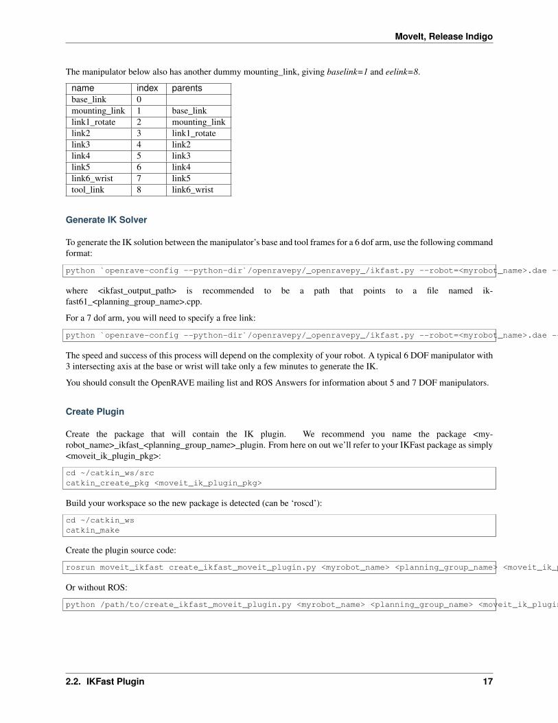
The manipulator below also has another dummy mounting_link, giving baselink=1 and eelink=8.
name index parentsbase_link 0mounting_link 1 base_linklink1_rotate 2 mounting_linklink2 3 link1_rotatelink3 4 link2link4 5 link3link5 6 link4link6_wrist 7 link5tool_link 8 link6_wrist
Generate IK Solver
To generate the IK solution between the manipulator’s base and tool frames for a 6 dof arm, use the following commandformat:
python `openrave-config --python-dir`/openravepy/_openravepy_/ikfast.py --robot=<myrobot_name>.dae --iktype=transform6d --baselink=1 --eelink=8 --savefile=<ikfast_output_path>
where <ikfast_output_path> is recommended to be a path that points to a file named ik-fast61_<planning_group_name>.cpp.
For a 7 dof arm, you will need to specify a free link:
python `openrave-config --python-dir`/openravepy/_openravepy_/ikfast.py --robot=<myrobot_name>.dae --iktype=transform6d --baselink=1 --eelink=8 --freeindex=4 --savefile=<ikfast_output_path>
The speed and success of this process will depend on the complexity of your robot. A typical 6 DOF manipulator with3 intersecting axis at the base or wrist will take only a few minutes to generate the IK.
You should consult the OpenRAVE mailing list and ROS Answers for information about 5 and 7 DOF manipulators.
Create Plugin
Create the package that will contain the IK plugin. We recommend you name the package <my-robot_name>_ikfast_<planning_group_name>_plugin. From here on out we’ll refer to your IKFast package as simply<moveit_ik_plugin_pkg>:
cd ~/catkin_ws/srccatkin_create_pkg <moveit_ik_plugin_pkg>
Build your workspace so the new package is detected (can be ‘roscd’):
cd ~/catkin_wscatkin_make
Create the plugin source code:
rosrun moveit_ikfast create_ikfast_moveit_plugin.py <myrobot_name> <planning_group_name> <moveit_ik_plugin_pkg> <ikfast_output_path>
Or without ROS:
python /path/to/create_ikfast_moveit_plugin.py <myrobot_name> <planning_group_name> <moveit_ik_plugin_pkg> <ikfast_output_path>
2.2. IKFast Plugin 17

MoveIt, Release Indigo
Parameters
• myrobot_name - name of robot as in your URDF
• planning_group_name - name of the planning group you would like to use this solver for, as referenced in yourSRDF and kinematics.yaml
• moveit_ik_plugin_pkg - name of the new package you just created
• ikfast_output_path - file path to the location of your generated IKFast output.cpp file
This will generate a new source file <myrobot_name>_<planning_group_name>_ikfast_moveit_plugin.cpp in the src/directory, and modify various configuration files.
Build your workspace again to create the ik plugin:
cd ~/catkin_wscatkin_make
This will build the new plugin library lib/lib<myrobot_name>_<planning_group_name>_moveit_ikfast_moveit_plugin.sothat can be used with MoveIt!
Usage
The IKFast plugin should function identically to the default KDL IK Solver, but with greatly increased performance.The MoveIt configuration file is automatically edited by the moveit_ikfast script but you can switch between the KDLand IKFast solvers using the kinematics_solver parameter in the robot’s kinematics.yaml file
rosed <myrobot_name>_moveit_config/config/kinematics.yaml
Edit these parts:
<planning_group_name>:kinematics_solver: <moveit_ik_plugin_pkg>/IKFastKinematicsPlugin
-OR-kinematics_solver: kdl_kinematics_plugin/KDLKinematicsPlugin
Test the Plugin
Use the MoveIt Rviz Motion Planning Plugin and use the interactive markers to see if correct IK Solutions are found.
Updating the Plugin
If any future changes occur with MoveIt! or IKFast, you might need to re-generate this plugin using our scripts.To allow you to easily do this, a bash script is automatically created in the root of your IKFast package, namedupdate_ikfast_plugin.sh. This does the same thing you did manually earlier, but uses the IKFast solution header filethat is copied into the ROS package.
2.3 Planning Scene/C++ API
The :planning_scene:‘PlanningScene‘ class provides the main interface that you will use for collision checking andconstraint checking. In this tutorial, we will explore the C++ interface to this class.
18 Chapter 2. Advanced Tutorials

MoveIt, Release Indigo
2.3.1 The entire code
The entire code can be seen :codedir:‘here in the moveit_pr2 github project<planning>‘.
2.3.2 Compiling the code
Follow the instructions for compiling code from source.
2.3.3 The launch file
The entire launch file is here on github. All the code in this tutorial can be compiled and run from thepr2_moveit_tutorials package that you have as part of your MoveIt! setup.
2.3.4 Running the code
Roslaunch the launch file to run the code directly from pr2_moveit_tutorials:
roslaunch pr2_moveit_tutorials planning_scene_tutorial.launch
2.3.5 Expected Output
The output should look something like this, though we are using random joint values so some things may be different:
[ INFO] [1385487628.853237681]: Test 1: Current state is not in self collision[ INFO] [1385487628.857680844]: Test 2: Current state is in self collision[ INFO] [1385487628.861798756]: Test 3: Current state is not in self collision[ INFO] [1385487628.861876838]: Current state is not valid[ INFO] [1385487628.866177315]: Test 4: Current state is in self collision[ INFO] [1385487628.866228020]: Contact between: l_shoulder_pan_link and r_forearm_link[ INFO] [1385487628.866259030]: Contact between: l_shoulder_pan_link and r_shoulder_lift_link[ INFO] [1385487628.866305963]: Contact between: l_shoulder_pan_link and r_shoulder_pan_link[ INFO] [1385487628.866331036]: Contact between: l_shoulder_pan_link and r_upper_arm_link[ INFO] [1385487628.866358135]: Contact between: l_shoulder_pan_link and r_upper_arm_roll_link[ INFO] [1385487628.870629418]: Test 5: Current state is not in self collision[ INFO] [1385487628.877406467]: Test 6: Current state is not in self collision[ INFO] [1385487628.879610797]: Test 7: Random state is not constrained[ INFO] [1385487628.880027331]: Test 8: Random state is not constrained[ INFO] [1385487628.880315077]: Test 9: Random state is not constrained[ INFO] [1385487628.880377445]: Test 10: Random state is feasible[ INFO] [1385487628.887157707]: Test 10: Random state is not valid
2.4 Planning Scene/ROS API
In this tutorial, we will examine the use of planning scene diffs to perform two operations:
• Adding and removing objects into the world
• Attaching and detaching objects to the robot
2.4. Planning Scene/ROS API 19
MoveIt, Release Indigo
2.4.1 The entire code
The entire code can be seen :codedir:‘here in the moveit_pr2 github project<planning>‘.
2.4.2 Compiling the code
Follow the instructions for compiling code from source.
2.4.3 The launch file
The entire launch file is here on github. All the code in this tutorial can be compiled and run from thepr2_moveit_tutorials package that you have as part of your MoveIt! setup.
2.4.4 Running the code
Roslaunch the launch file to run the code directly from pr2_moveit_tutorials:
roslaunch pr2_moveit_tutorials planning_scene_ros_api_tutorial.launch
2.4.5 Expected Output
In rviz, you should be able to see the following:
• Object appear in the planning scene
• Object gets attached to the robot
• Object gets detached from the robot
• Object is removed from the planning scene
2.5 Motion Planners/C++ API
In MoveIt!, the motion planners are loaded using a plugin infrastructure. This allows MoveIt! to load motion plannersat runtime. In this example, we will run through the C++ code required to do this.
2.5.1 The entire code
The entire code can be seen :codedir:‘here in the moveit_pr2 github project<planning>‘.
2.5.2 Compiling the code
Follow the instructions for compiling code from source.
2.5.3 The launch file
The entire launch file is here on github. All the code in this tutorial can be compiled and run from thepr2_moveit_tutorials package that you have as part of your MoveIt! setup.
20 Chapter 2. Advanced Tutorials

MoveIt, Release Indigo
2.5.4 Running the code
Roslaunch the launch file to run the code directly from pr2_moveit_tutorials:
roslaunch pr2_moveit_tutorials motion_planning_api_tutorial.launch
2.5.5 Expected Output
In Rviz, we should be able to see four trajectories being replayed eventually:
1. The robot moves its right arm to the pose goal in front of it,
2. The robot moves its right arm to the joint goal to the side,
3. The robot moves its right arm back to the original pose goal in front of it,
4. The robot moves its right arm back to a new pose goal while maintaining the end-effector level.
2.6 Motion Planners/C++ API
In MoveIt!, the motion planners are setup to plan paths. However, there are often times when we may want to pre-process the motion planning request or post-process the planned path (e.g. for time parameterization). In such cases,we use the planning pipeline which chains a motion planner with pre-processing and post-processing stages. The preand post-processing stages, called planning request adapters, can be configured by name from the ROS parameterserver. In this tutorial, we will run you through the C++ code to instantiate and call such a planning pipeline.
2.6.1 The entire code
The entire code can be seen :codedir:‘here in the moveit_pr2 github project<planning>‘.
2.6.2 Compiling the code
Follow the instructions for compiling code from source.
2.6.3 The launch file
The entire launch file is here on github. All the code in this tutorial can be compiled and run from thepr2_moveit_tutorials package that you have as part of your MoveIt! setup.
2.6.4 Running the code
Roslaunch the launch file to run the code directly from pr2_moveit_tutorials:
roslaunch pr2_moveit_tutorials motion_planning_interface_tutorial.launch
2.6. Motion Planners/C++ API 21

MoveIt, Release Indigo
2.6.5 Expected Output
In Rviz, we should be able to see three trajectories being replayed eventually:
1. The robot moves its right arm to the pose goal in front of it,
2. The robot moves its right arm to the joint goal to the side,
3. The robot moves its right arm back to the original pose goal in front of it,
2.7 Controller Manager Tutorials
MoveIt! comes with a series of fake trajectory controllers to be used in simulation. For example, the demo.launchgenerated by MoveIt’s setup assistant, employs fake controllers for nice visualization in rviz.
For configuration, edit the file config/fake_controllers.yaml, and adjust the desired controller type. Thefollowing controllers are available:
• interpolate: perform smooth interpolation between via points - the default for visualization
• via points: traverse via points, w/o interpolation in between - useful for visual debugging
• last point: warp directly to the last point of the trajectory - fastest method for offline benchmarking
rate: 10 (Hz, used for interpolation controller)controller_list:
- name: fake_arm_controllertype: interpolate | via points | last pointjoints:
- joint_1- joint_2- joint_3- joint_4- joint_5- joint_6
- name: fake_gripper_controllerjoints:
[]
In order to load an initial pose, one can have a list of (group, pose) pairs as follows:
initial:- group: armpose: home
22 Chapter 2. Advanced Tutorials

CHAPTER 3
Configuration Tutorials
3.1 Kinematics/Parameters
In this section, we will examine some of the parameters for configuring kinematics for your robot.
3.1.1 The kinematics.yaml file
The kinematics.yaml file generated by the MoveIt! Setup Assistant is the primary configuration file for kinematics forMoveIt!. You can see an entire example file for the PR2 robot in the moveit_pr2 github project
right_arm:kinematics_solver: pr2_arm_kinematics/PR2ArmKinematicsPluginkinematics_solver_search_resolution: 0.001kinematics_solver_timeout: 0.05kinematics_solver_attempts: 3
right_arm_and_torso:kinematics_solver: kdl_kinematics_plugin/KDLKinematicsPluginkinematics_solver_search_resolution: 0.005kinematics_solver_timeout: 0.05
Parameters
The set of available parameters include:
• kinematics_solver: The name of your kinematics solver plugin. Note that thismust match the name that you specified in the plugin description file, e.g.example_kinematics/ExampleKinematicsPlugin
• kinematics_solver_search_resolution: This specifies the resolution that a solver might use to search overthe redundant space for inverse kinematics, e.g. using one of the joints for a 7 DOF arm specified as theredundant joint.
• kinematics_solver_timeout: This is a default timeout specified (in seconds) for each internal iteration thatthe inverse kinematics solver may perform. A typical iteration (e.g. for a numerical solver) will consistof a random restart from a seed state followed by a solution cycle (for which this timeout is applica-ble). The solver may attempt multiple restarts - the default number of restarts is defined by the kinemat-ics_solver_attempts parameter below.
• kinematics_solver_attempts: The number of random restarts that will be performed on the solver. Eachsolution cycle after the restart will have a timeout defined by the kinematics_solver_timeout parameterabove. In general, it is better to set this timeout low and fail quickly in an individual solution cycle.
23

MoveIt, Release Indigo
The KDL Kinematics Plugin
The KDL kinematics plugin wraps around the numerical inverse kinematics solver provided by the Orocos KDL package.
• This is the default kinematics plugin currently used by MoveIt!
• It obeys joint limits specified in the URDF (and will use the safety limits if they are specified in the URDF).
• The KDL kinematics plugin currently only works with serial chains.
The LMA Kinematics Plugin
The LMA (Levenberg-Marquardt) kinematics plugin also wraps around a numerical inverse kinematics solver provided by the Orocos KDL package.
• It obeys joint limits specified in the URDF (and will use the safety limits if they are specified in the URDF).
• The LMA kinematics plugin currently only works with serial chains.
• Usage: kinematics_solver: lma_kinematics_plugin/LMAKinematicsPlugin
3.1.2 Position Only IK
Position only IK can easily be enabled (only if you are using the KDL Kinematics Plugin) by adding the followingline to your kinematics.yaml file (for the particular group that you want to solve IK for):
position_only_ik: True
3.2 3D Perception/Configuration
In this section, we will walk through configuring the 3D sensors on your robot with MoveIt!. The primary component in MoveIt! that deals with 3D perception is the Occupancy Map Updater. The updater uses a plugin architecture to process different types of input. The currently available plugins in MoveIt! are:
• The PointCloud Occupany Map Updater: which can take as input point clouds(sensor_msgs/PointCloud2)
• The Depth Image Occupancy Map Updater: which can take as input Depth Images(sensor_msgs/Image)
3.2.1 YAML Configuration file (Point Cloud)
We will have to generate a YAML configuration file for configuring the 3D sensors. An example file for processingpoint clouds can be found in the moveit_pr2 github project
sensors:- sensor_plugin: occupancy_map_monitor/PointCloudOctomapUpdaterpoint_cloud_topic: /head_mount_kinect/depth_registered/pointsmax_range: 5.0point_subsample: 1padding_offset: 0.1padding_scale: 1.0filtered_cloud_topic: filtered_cloud
The general parameters are:
24 Chapter 3. Configuration Tutorials

MoveIt, Release Indigo
• sensor_plugin: The name of the plugin that we are using.
Parameters specific to the Point cloud updater are:
• point_cloud_topic: This specifies the topic to listen on for a point cloud.
• max_range: (in m) Points further than this will not be used.
• point_subsample: Choose one of every point_subsample points.
• padding_offset: The size of the padding (in cm).
• padding_scale:
• filtered_cloud_topic: The topic on which the filtered cloud will be published (mainly for debugging). Thefiltering cloud is the resultant cloud after self-filtering has been performed.
3.2.2 YAML Configuration file (Depth Map)
We will have to generate a rgbd.yaml configuration file for configuring the 3D sensors. An example file for processingpoint clouds can be found in the moveit_advanced github project
sensors:- sensor_plugin: occupancy_map_monitor/DepthImageOctomapUpdaterimage_topic: /head_mount_kinect/depth_registered/image_rawqueue_size: 5near_clipping_plane_distance: 0.3far_clipping_plane_distance: 5.0shadow_threshold: 0.2padding_scale: 4.0padding_offset: 0.03filtered_cloud_topic: filtered_cloud
The general parameters are:
• sensor_plugin: The name of the plugin that we are using.
Parameters specific to the Depth Map updater are:
• image_topic: This specifies the topic to listen on for a depth image.
• queue_size: he number of images to queue up
• near_clipping_plane_distance:
• far_clipping_plane_distance:
• shadow_threshold:
• padding_offset: The size of the padding (in cm).
• padding_scale:
• filtered_cloud_topic: The topic on which the filtered cloud will be published (mainly for debugging). Thefiltering cloud is the resultant cloud after self-filtering has been performed.
3.2.3 Update the launch file
Add the YAML file to the launch script
You will now need to update the moveit_sensor_manager.launch file in the “launch” directory of your MoveIt! con-figuration directory with this sensor information (this file is auto-generated by the Setup Assistant but is empty). You
3.2. 3D Perception/Configuration 25

MoveIt, Release Indigo
will need to add the following line into that file to configure the set of sensor sources for MoveIt! to use:
<rosparam command="load" file="$(find my_moveit_config)/config/sensors_kinect.yaml" />
Note that you will need to input the path to the right file you have created above.
Octomap Configuration
You will also need to configure the Octomap by adding the following lines into the moveit_sensor_manager.launch:
<param name="octomap_frame" type="string" value="odom_combined" /><param name="octomap_resolution" type="double" value="0.05" /><param name="max_range" type="double" value="5.0" />
MoveIt! uses an octree based framework to represent the world around it. The Octomap parameters above are configuration parameters for this representation:
• octomap_frame: specifies the coordinate frame in which this representation will be stored. If you areworking with a mobile robot, this frame should be a fixed frame in the world.
• octomap_resolution: specifies the resolution at which this representation is maintained (in meters).
• max_range: specifies the maximum range value to be applied for any sensor input to this node.
3.3 Controllers/Configuration
In this section, we will walk through configuring MoveIt! with the controllers on your robot. We will assumethat your robot offers a FollowJointTrajectory action service for the arms on your robot and (optionally)a GripperCommand service for your gripper.
3.3.1 YAML Configuration
The first file to create is a YAML configuration file (call it controllers.yaml and place it in the config directory ofyour MoveIt! config directory). This will specify the controller configuration for your robot. Here’s an examplefile for configuring a FollowJointTrajectory action controller for two different arms (left and right) and aGripperCommand gripper controller for two grippers
controller_list:- name: r_arm_controlleraction_ns: follow_joint_trajectorytype: FollowJointTrajectorydefault: truejoints:
- r_shoulder_pan_joint- r_shoulder_lift_joint- r_upper_arm_roll_joint- r_elbow_flex_joint- r_forearm_roll_joint- r_wrist_flex_joint- r_wrist_roll_joint
- name: l_arm_controlleraction_ns: follow_joint_trajectorytype: FollowJointTrajectorydefault: truejoints:
26 Chapter 3. Configuration Tutorials
MoveIt, Release Indigo
- l_shoulder_pan_joint- l_shoulder_lift_joint- l_upper_arm_roll_joint- l_elbow_flex_joint- l_forearm_roll_joint- l_wrist_flex_joint- l_wrist_roll_joint
- name: gripper_controlleraction_ns: gripper_actiontype: GripperCommanddefault: truejoints:
- l_gripper_joint- r_gripper_joint
We will walk through the parameters for both types of controllers.
3.3.2 FollowJointTrajectory Controller Interface
The parameters are:
• name: The name of the controller. (See debugging information below for important notes).
• action_ns: The action namespace for the controller. (See debugging information below for importantnotes).
• type: The type of action being used (here FollowJointTrajectory).
• default: The default controller is the primary controller chosen by MoveIt! for communicating with aparticular set of joints.
• joints: Names of all the joints that are being addressed by this interface.
3.3.3 GripperCommand Controller Interface
The parameters are:
• name: The name of the controller. (See debugging information below for important notes).
• action_ns: The action namespace for the controller. (See debugging information below for importantnotes).
• type: The type of action being used (here GripperCommand).
• default: The default controller is the primary controller chosen by MoveIt! for communicating with aparticular set of joints.
• joints: Names of all the joints that are being addressed by this interface.
3.3.4 Create the Controller launch file
Now, create the controller launch file (call it robot_moveit_controller_manager.launch where robot is the name of yourrobot - the robot name needs to match the name specified when you created your MoveIt! config directory).
Add the following lines to this file
3.3. Controllers/Configuration 27

MoveIt, Release Indigo
<launch><!-- Set the param that trajectory_execution_manager needs to find the controller plugin --><arg name="moveit_controller_manager" default="moveit_simple_controller_manager/MoveItSimpleControllerManager" /><param name="moveit_controller_manager" value="$(arg moveit_controller_manager)"/><!-- load controller_list --><rosparam file="$(find my_robot_name_moveit_config)/config/controllers.yaml"/>
</launch>
MAKE SURE to replace my_robot_name_moveit_config with the correct path for your MoveIt! config directory.
Now, you should be ready to have MoveIt! talk to your robot.
3.3.5 Debugging Information
The FollowJointTrajectory or GripperCommand interfaces on your robot must be communicating in thenamespace: \name\action_ns. In the above example, you should be able to see the following topics (usingrostopic list) on your robot:
• /r_arm_controller/follow_joint_trajectory/goal
• /r_arm_controller/follow_joint_trajectory/feedback
• /r_arm_controller/follow_joint_trajectory/result
• /l_arm_controller/follow_joint_trajectory/goal
• /l_arm_controller/follow_joint_trajectory/feedback
• /l_arm_controller/follow_joint_trajectory/result
• /gripper_controller/gripper_action/goal
• /gripper_controller/gripper_action/feedback
• /gripper_controller/gripper_action/result
You should also be able to see (using rostopic info topic_name) that the topics are published/subscribed to by thecontrollers on your robot and also by the move_group node.
3.4 OMPL Interface
3.4.1 OMPL Optimization Objective Tutorial
Several planners that are part of the OMPL planning library are capable of optimizing for a specified optimizationobjective. This tutorial describes that steps that are needed to configure these objectives. The optimal planners that arecurrently exposed to MoveIt! are:
• geometric::RRTstar
• geometric::PRMstar
And the following optimization objectives are available:
• PathLengthOptimizationObjective (Default)
• MechanicalWorkOptimizationObjective
• MaximizeMinClearanceObjective
• StateCostIntegralObjective
28 Chapter 3. Configuration Tutorials
MoveIt, Release Indigo
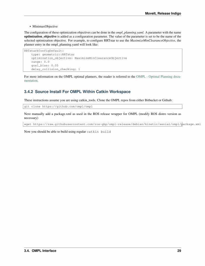
• MinimaxObjective
The configuration of these optimization objectives can be done in the ompl_planning.yaml. A parameter with the nameoptimization_objective is added as a configuration parameter. The value of the parameter is set to be the name of theselected optimization objective. For example, to configure RRTstar to use the MaximizeMinClearanceObjective, theplanner entry in the ompl_planning.yaml will look like:
RRTstarkConfigDefault:type: geometric::RRTstaroptimization_objective: MaximizeMinClearanceObjectiverange: 0.0goal_bias: 0.05delay_collision_checking: 1
For more information on the OMPL optimal planners, the reader is referred to the OMPL - Optimal Planning docu-mentation.
3.4.2 Source Install For OMPL Within Catkin Workspace
These instructions assume you are using catkin_tools. Clone the OMPL repos from either Bitbucket or Github:
git clone https://github.com/ompl/ompl
Next manually add a package.xml as used in the ROS release wrapper for OMPL (modify ROS distro version asnecessary)
wget https://raw.githubusercontent.com/ros-gbp/ompl-release/debian/kinetic/xenial/ompl/package.xml
Now you should be able to build using regular catkin build
3.4. OMPL Interface 29