RELEASE GUIDE - geospatial-insight.com · Define Deep Learning 2D Convolution Layer ... Get AWS...
107
RELEASE GUIDE ERDAS IMAGINE 2018 February 27, 2018
Transcript of RELEASE GUIDE - geospatial-insight.com · Define Deep Learning 2D Convolution Layer ... Get AWS...
RELEASE GUIDE ERDAS IMAGINE 2018
February 27, 2018

February 27, 2018 2
Contents
About This Release .................................................................................................................. 8
ERDAS IMAGINE Product Tiers .............................................................................................. 8
New Platforms .......................................................................................................................... 8
64-Bit .................................................................................................................................... 8
ERDAS IMAGINE 2018 (64-bit) ...................................................................................... 9
ERDAS IMAGINE 2018 (32-bit) ...................................................................................... 9
Support of New Feature / Vector Data Formats .................................................................. 10
ArcGIS 10.5.1 ..................................................................................................................... 10
ERDAS Foundation Deprecated ......................................................................................... 10
New Licensing .................................................................................................................... 11
New Technology ..................................................................................................................... 12
Machine Learning Classification Operators ........................................................................ 12
NNDiffuse Pan Sharpening Operator .................................................................................. 12
Feature Extraction Operators ............................................................................................. 13
Other New Operators for Spatial Modeler ........................................................................... 13
Analyze Radiance ......................................................................................................... 13
Classify Using K-Means ................................................................................................ 14
Classify Using Deep Learning ....................................................................................... 15
Classify Using Machine Learning .................................................................................. 15
Compute Axis Length .................................................................................................... 15
Compute Circularity ...................................................................................................... 16
Compute Compactness ................................................................................................. 16
Compute Concavity ....................................................................................................... 17
Compute Convexity ....................................................................................................... 17
Compute Corner Count ................................................................................................. 17
Compute Eccentricity .................................................................................................... 18
February 27, 2018 3
Compute Horizontal Skewness ..................................................................................... 18
Compute Orientation ..................................................................................................... 18
Compute Orthogonality ................................................................................................. 19
Compute Primary Axis Skewness ................................................................................. 19
Compute Rectangularity ................................................................................................ 19
Compute Secondary Axis Skewness ............................................................................ 19
Compute Vertical Skewness ......................................................................................... 20
Convert ......................................................................................................................... 20
Convert To Surface ....................................................................................................... 20
Create Bounding Box .................................................................................................... 21
Create Centerline .......................................................................................................... 21
Create Centerpoint ........................................................................................................ 21
Create Centroid ............................................................................................................. 22
Create ConvexHull ........................................................................................................ 22
Create File Dataset Reference ...................................................................................... 22
Create Fitted Bounding Box .......................................................................................... 23
Create Oriented Bounding Box ..................................................................................... 24
Create Skeleton ............................................................................................................ 25
Data Information ........................................................................................................... 25
Define Deep Learning 2D Convolution Layer ................................................................ 25
Define Deep Learning 2D pooling Layer ....................................................................... 26
Define Deep Learning Activation Layer ......................................................................... 26
Define Deep Learning Dense Layer .............................................................................. 26
Define Deep Learning Flatten Layer ............................................................................. 27
Define Functional Attributes .......................................................................................... 27
Define Processing Area ................................................................................................ 27
Eliminate Unwanted Areas ............................................................................................ 28
February 27, 2018 4
Extract NITF Shapefile .................................................................................................. 28
Find Item ....................................................................................................................... 29
Generic Atmospheric Correction ................................................................................... 29
Get AWS Landsat 8 Scenes ......................................................................................... 30
Get Band IDs ................................................................................................................ 31
Get DRA Params .......................................................................................................... 32
Get ECW Options ......................................................................................................... 32
Get JFIF Options ........................................................................................................... 33
Get JPEG 2000 Options ................................................................................................ 34
Get Multispectral DRA Params ..................................................................................... 34
Get NITF 2.x Options .................................................................................................... 35
Get Preference Value ................................................................................................... 35
Get Raster Values By Percentage ................................................................................ 35
Get Referenced Dataset ............................................................................................... 37
Get SIPS Defaults ......................................................................................................... 37
Generate Functional Attributes ..................................................................................... 38
Initialize CART .............................................................................................................. 38
Initialize Deep Intellect .................................................................................................. 38
Initialize Inception ......................................................................................................... 39
initialize K-Nearest Neighbors ....................................................................................... 39
Initialize Naive Bayes .................................................................................................... 39
Initialize Random Forest ............................................................................................... 39
Initialize SVM ................................................................................................................ 40
Intersect Features ......................................................................................................... 40
Kurtosis Texture Per Feature ........................................................................................ 40
Machine Intellect Information ........................................................................................ 41
Machine Intellect Input .................................................................................................. 41
February 27, 2018 5
Machine Intellect Output ............................................................................................... 42
Mask features ............................................................................................................... 42
Merge Features ............................................................................................................. 42
Mean Euclidian Distance Texture Per Feature .............................................................. 42
Metadata Input .............................................................................................................. 43
Normalize Height .......................................................................................................... 43
Orthogonalize Geometry ............................................................................................... 44
Pan Sharpen By NNDiffuse ........................................................................................... 44
Range Stretch ............................................................................................................... 44
Raster Cache ................................................................................................................ 44
Raster Statistics Per Feature ........................................................................................ 45
Read Sensor Metadata ................................................................................................. 45
Remove Attributes ........................................................................................................ 46
Rename Attributes ........................................................................................................ 46
Select Attributes ............................................................................................................ 47
Set Band Names ........................................................................................................... 47
Set Primary Geometry................................................................................................... 48
Simplify Geometry ......................................................................................................... 48
Skew Texture Per Feature ............................................................................................ 49
Split By Skeleton ........................................................................................................... 50
Stack Count .................................................................................................................. 50
Tasseled Cap ................................................................................................................ 51
Update Statistics ........................................................................................................... 51
Variance Texture Per Feature ....................................................................................... 51
General Spatial Modeler ..................................................................................................... 52
Acceptable Values and other Input Contraints .............................................................. 52
Stack <Statistics> Operators ......................................................................................... 53
February 27, 2018 6
Leverage investments in other Geospatial products in Spatial Model Editor ................. 53
Spatial Models as Operators ......................................................................................... 54
General ERDAS IMAGINE ................................................................................................. 55
New Inquire Cursor panel ............................................................................................. 55
Google Earth Pro Live-Link ........................................................................................... 59
Use your own Change algorithms in Zonal Change Detection ...................................... 59
Support for EPSG ......................................................................................................... 60
GDA2020 ...................................................................................................................... 60
Predefined Zoom Scales ............................................................................................... 60
Subset in Batch ............................................................................................................. 62
Edit Image Metadata (Image Command Tool) in Batch ................................................. 63
IMAGINE SAR Feature User Guide .............................................................................. 66
New Sensors and Formats ................................................................................................. 66
Sentinel-2 Update ......................................................................................................... 66
Sentinel-2 “True Color” band combination..................................................................... 66
Landsat 7 and 8 from USGS ......................................................................................... 67
BPF Point Cloud format ................................................................................................ 67
Esri ASCII Raster direct read ........................................................................................ 67
Sensor Independent Complex Data (SICD) .................................................................. 67
Exploit multi-segment NITF ........................................................................................... 67
Open NITF Segments ................................................................................................... 67
SIPS Image Chains ....................................................................................................... 68
Security Indicators ........................................................................................................ 68
Planet imagery .............................................................................................................. 68
WorldView-4.................................................................................................................. 68
External Pyramids ......................................................................................................... 68
Other New Sensors ....................................................................................................... 68
February 27, 2018 7
Geospatial PDF .................................................................................................................. 69
IMAGINE SAR Interferometry ............................................................................................. 69
Sentinel-1 Swath Time-Series Coherence Change Detection (CCD) ............................ 69
Multi-polar CCD Analysis .............................................................................................. 69
Improved Interferometric Coregistration ........................................................................ 69
System Requirements ........................................................................................................... 70
ERDAS IMAGINE ............................................................................................................... 70
ERDAS IMAGINE System Requirements Notes ................................................................. 72
PRO600 .............................................................................................................................. 73
PRO600 System Requirements Notes ............................................................................... 74
Issues Resolved ..................................................................................................................... 75
IMAGINE Essentials ........................................................................................................... 75
IMAGINE Advantage .......................................................................................................... 86
IMAGINE Objective ............................................................................................................ 88
IMAGINE Photogrammetry ................................................................................................. 89
IMAGINE Professional ........................................................................................................ 91
IMAGINE SAR Interferometry ............................................................................................. 91
Spatial Modeler................................................................................................................... 92
Stereo Analyst for ERDAS IMAGINE ................................................................................ 102
IMAGINE Terrain Editor .................................................................................................... 102
IMAGINE Expansion Pack – 3D ....................................................................................... 103
IMAGINE Expansion Pack – NITF .................................................................................... 103
ERDAS IMAGINE Installation ........................................................................................... 104
ERDAS ER Mapper .......................................................................................................... 104
About Us ............................................................................................................................... 105
About This Release
February 27, 2018 8
ABOUT THIS RELEASE This document describes the enhancements for ERDAS IMAGINE 2018 (v16.5), including IMAGINE Photogrammetry (formerly LPS Core) and ERDAS ER Mapper. Although the information in this document is current as of the product release, see the Hexagon Geospatial Support website for the most current version.
This release includes both enhancements and fixes. For information on fixes that were made to ERDAS IMAGINE for this release, see the Issues Resolved section.
This document is only an overview and does not provide all the details about the product's capabilities. See the online help and other documents provided with ERDAS IMAGINE for more information.
ERDAS IMAGINE PRODUCT TIERS ERDAS IMAGINE® performs advanced remote sensing analysis and spatial modeling to create new information. In addition, with ERDAS IMAGINE, you can visualize your results in 2D, 3D, movies, and on cartographic-quality map compositions. The core of the ERDAS IMAGINE product suite is engineered to scale with your geospatial data production needs. Optional modules (add-ons) providing specialized functionalities are also available to enhance your productivity and capabilities.
IMAGINE Essentials® is the entry-level image processing product for map creation and simple feature collection tools. IMAGINE Essentials enables serial batch processing.
IMAGINE Advantage® enables advanced spectral processing, image registration, mosaicking and image analysis, and change detection capabilities. IMAGINE Advantage enables parallel batch processing for accelerated output.
IMAGINE Professional® includes a production toolset for advanced spectral, hyperspectral, and radar processing, and spatial modeling. Includes ERDAS ER Mapper.
NEW PLATFORMS
64-BIT As imagery gets larger and larger (for example, a single Sentinel-2 image can be over 8 GB in size, even when JPEG 2000 compressed) it becomes increasingly urgent to be able to make fuller use of the resources provided by modern computer systems, especially the additional memory that is usually installed. In prior versions of ERDAS IMAGINE we have made extensive progress in providing background processing (such as from Spatial Modeler) and specific applications (such as Semi Global Matching) that run in 64-bit. However the Ribbon interface itself (ewkspace.exe) was always launched as a 32-bit application - it was only select applications that could be launched from, but run independently of, the Ribbon that would execute in 64-bit. This meant that the applications embedded within the Ribbon, such as the 2D View and the Spatial Model Editor, also ran as 32-bit and consequently were limited to utilizing, at best, 4GB of memory each.
One of the main reasons why the Ribbon remained 32-bit was that some functionality that could be run from it (especially functionality depending on third-party libraries) could not be modified to run 64-bit and so everything needed to run 32-bit.

New Platforms
February 27, 2018 9
With ERDAS IMAGINE 2018 it has consequently been decided to offer two distinct versions of the ERDAS IMAGINE Ribbon interface that the user can opt to launch and utilize:
ERDAS IMAGINE 2018 (64-BIT)
Launching ERDAS IMAGINE 2018 (64-bit) provides numerous advantages, which should make this the preferred mode to use. Primary amongst these is that 2D Views will now be running in a 64-bit environment, enabling you to use memory above the 4GB limit imposed on 32-bit applications. This means less likelihood of encountering "out of memory" errors.
Another advantage is that Spatial Models will be able to process large datasets more efficiently even when executed within the Spatial Model Editor interface. Previously, Models might have to be executed in Background mode to take advantage of 64-bit execution, which meant that the progress of the model was more difficult to monitor and, if a problem occurred, address by modifications of the Model. Now the Model can be executed efficiently within the Editor and modifications to the Model made directly if required.
ERDAS IMAGINE 2018 (32-BIT)
It should be emphasized that both modes of ERDAS IMAGINE 2018 still benefit from the same 64-bit capabilities that were present in ERDAS IMAGINE 2016. So even if you elect to launch ERDAS IMAGINE 2018 (32-bit), it is the Ribbon that is running 32-bit, but other applications can still be executed 64-bit, such as electing to run a Spatial Model in background. Consequently, even though it is termed "ERDAS IMAGINE 2018 (32-bit)", you will need a 64-bit version of Windows, and a 64-bit CPU, to install and launch ERDAS IMAGINE 2018 (32-bit).
But why launch the ribbon in 32-bit mode if there's a 64-bit version available? As mentioned earlier, there are some very limited capabilities that run from the Ribbon that remain unable to be updated to run in 64-bit. Consequently, these capabilities are absent from ERDAS IMAGINE 2018 (64-bit). If you need to routinely use these features, we are providing ERDAS IMAGINE 2018 (32-bit) so that all functionality that was provided in ERDAS IMAGINE 2016 is still available to the user. Functionality that is only available in ERDAS IMAGINE 2018 (32-bit) includes:
1. Raster formats
a. ER Mapper Algorithm
b. GRID
c. GRID Stack
d. ORACLE Georaster
e. SDE Raster
f. NITF 1.1 (NITF 2.0 and 2.1 are available in 64-bit)
g. VisionMap .sup
2. Vector formats
a. Arc Coverage
b. ArcGIS Geodatabase
c. SDE vector layer
New Platforms
February 27, 2018 10
3. MultiGen OpenFlight models in 3D View / VirtualGIS
4. TerraModeler TIN Terrain format
5. VisionMap Sensor model
6. Live link connection between ERDAS IMAGINE and GeoMedia.
If you routinely use any of these in your work then you might want to consider running ERDAS IMAGINE 2018 (32-bit) rather than ERDAS IMAGINE 2018 (64-bit).
SUPPORT OF NEW FEATURE / VECTOR DATA FORMATS
Support is now added for reading Features from PostGIS database (PostgreSQL 9.4 / PostGIS 2.2). Features are accessed via a PostGIS Feature Proxy (pfp).
Support for reading features from and writing to GeoCSV is also added with the following caveat.
Reading is supported for point features and features without geometries.
Writing is supported for all feature data. For Point feature data, both geometry and non-geometry attributes are written out to the CSV fie, while for other feature types, only the non-geometry attributes are written out to the CSV file.
Microsoft SQL Server 2014 can be used to store GeoMedia Features (.sfp).
ARCGIS 10.5.1
ERDAS IMAGINE 2018 has been tested and declared Supported when using an installed and licensed version of ArcGIS 10.1 through 10.5.1 in order to provide Geodatabase support libraries. Alternatively, the IMAGINE Geodatabase Support component (based on ArcGIS Engine 10.5) can be installed to provide Geodatabase support.
ERDAS FOUNDATION DEPRECATED
ERDAS IMAGINE no longer requires the installation of ERDAS Foundation as a pre-requisite. All capabilities from ERDAS Foundation are now consolidated within the ERDAS IMAGINE installer.
New Platforms
February 27, 2018 11
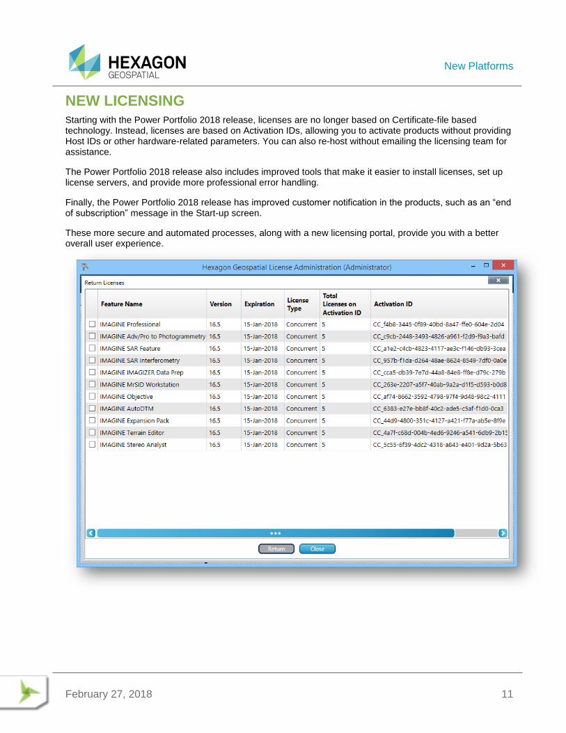
NEW LICENSING
Starting with the Power Portfolio 2018 release, licenses are no longer based on Certificate-file based technology. Instead, licenses are based on Activation IDs, allowing you to activate products without providing Host IDs or other hardware-related parameters. You can also re-host without emailing the licensing team for assistance.
The Power Portfolio 2018 release also includes improved tools that make it easier to install licenses, set up license servers, and provide more professional error handling.
Finally, the Power Portfolio 2018 release has improved customer notification in the products, such as an “end of subscription” message in the Start-up screen.
These more secure and automated processes, along with a new licensing portal, provide you with a better overall user experience.

New Technology
February 27, 2018 12
NEW TECHNOLOGY
MACHINE LEARNING CLASSIFICATION OPERATORS
Machine learning is the science of getting computers to act without being explicitly programmed. Stated in another way, it is a way of programming where computers are programmed to learn from data.
Machine learning algorithms are great for:
1. Problems for which existing solutions require a lot of hand-tuning or long lists of rules: one Machine
Learning algorithm can often simplify code and perform better.
2. Complex problems for which there is no good solution at all using a traditional approach: the best
Machine Learning techniques can find a solution.
3. Fluctuating environments: a Machine Learning system can adapt to new data.
4. Data mining - getting insights about complex problems and large amounts of data
Geospatial phenomena are non-linear, spatially and temporally variable and have multi-scale variability which creates challenges in geospatial analysis. With the proliferation of sensors around us, from micro satellites to UAVs, the volume of data has greatly increased. The complexity of geospatial phenomena and the deluge of data has made geospatial analysis using machine learning methods a natural fit.
We have introduced several machine learning algorithms based classification operators in Spatial Modeler that can be used to perform supervised and unsupervised raster and vector classification. The supervised classification operators need training data and attributes of the training data to be used in performing the classification, while the unsupervised classification operators only need attribute of the data to be used to separate the data into clusters.
Another set of classification operators based on deep learning algorithms are also introduced. These are a class of Machine learning algorithm that use deep neural networks to decide the attributes of the data that need to be used to perform classification.
A classification operator based on Inception, an award winning deep learning classification algorithm introduced by Google, is also introduced. The operator can be re-trained using user’s data to perform classification.
NNDIFFUSE PAN SHARPENING OPERATOR
The Nearest-neighbor diffusion-based (NNDiffuse) algorithm, originally developed by Sun, Chen and Messinger at Rochester Institute of Technology, is a state of the art pan sharpening technique, now available as an Operator so that you can build Spatial Models capable of deriving information from high resolution, multispectral data.
The example below shows how the NNDiffuse sharpened image, shown on the right, retains the spectral fidelity of the input, lower resolution multispectral image, shown on the left, while increasing the spatial resolution four-fold (from 2m pixels to 0.5m pixels):
New Technology
February 27, 2018 13
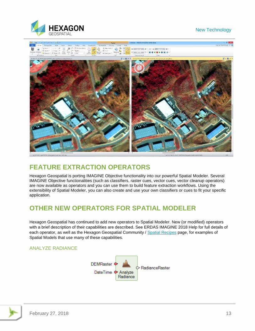
FEATURE EXTRACTION OPERATORS
Hexagon Geospatial is porting IMAGINE Objective functionality into our powerful Spatial Modeler. Several IMAGINE Objective functionalities (such as classifiers, raster cues, vector cues, vector cleanup operators) are now available as operators and you can use them to build feature extraction workflows. Using the extensibility of Spatial Modeler, you can also create and use your own classifiers or cues to fit your specific application.
OTHER NEW OPERATORS FOR SPATIAL MODELER
Hexagon Geospatial has continued to add new operators to Spatial Modeler. New (or modified) operators
with a brief description of their capabilities are described. See ERDAS IMAGINE 2018 Help for full details of
each operator, as well as the Hexagon Geospatial Community / Spatial Recipes page, for examples of
Spatial Models that use many of these capabilities.
ANALYZE RADIANCE
New Technology
February 27, 2018 14
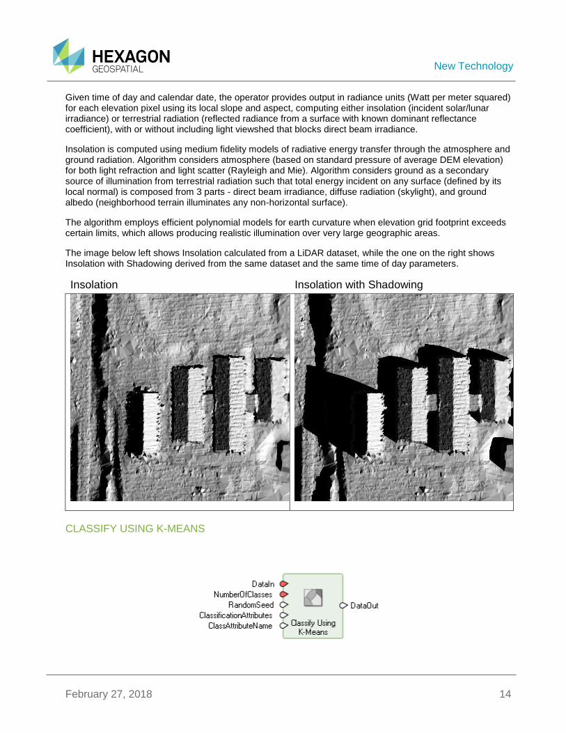
Given time of day and calendar date, the operator provides output in radiance units (Watt per meter squared) for each elevation pixel using its local slope and aspect, computing either insolation (incident solar/lunar irradiance) or terrestrial radiation (reflected radiance from a surface with known dominant reflectance coefficient), with or without including light viewshed that blocks direct beam irradiance.
Insolation is computed using medium fidelity models of radiative energy transfer through the atmosphere and ground radiation. Algorithm considers atmosphere (based on standard pressure of average DEM elevation) for both light refraction and light scatter (Rayleigh and Mie). Algorithm considers ground as a secondary source of illumination from terrestrial radiation such that total energy incident on any surface (defined by its local normal) is composed from 3 parts - direct beam irradiance, diffuse radiation (skylight), and ground albedo (neighborhood terrain illuminates any non-horizontal surface).
The algorithm employs efficient polynomial models for earth curvature when elevation grid footprint exceeds certain limits, which allows producing realistic illumination over very large geographic areas.
The image below left shows Insolation calculated from a LiDAR dataset, while the one on the right shows Insolation with Shadowing derived from the same dataset and the same time of day parameters.
Insolation Insolation with Shadowing
CLASSIFY USING K-MEANS
New Technology
February 27, 2018 15
K-Means is an unsupervised machine learning algorithm that classifies data into a specified number of classes while minimizing the sum of squares of distances between the data points and their corresponding class centroids.
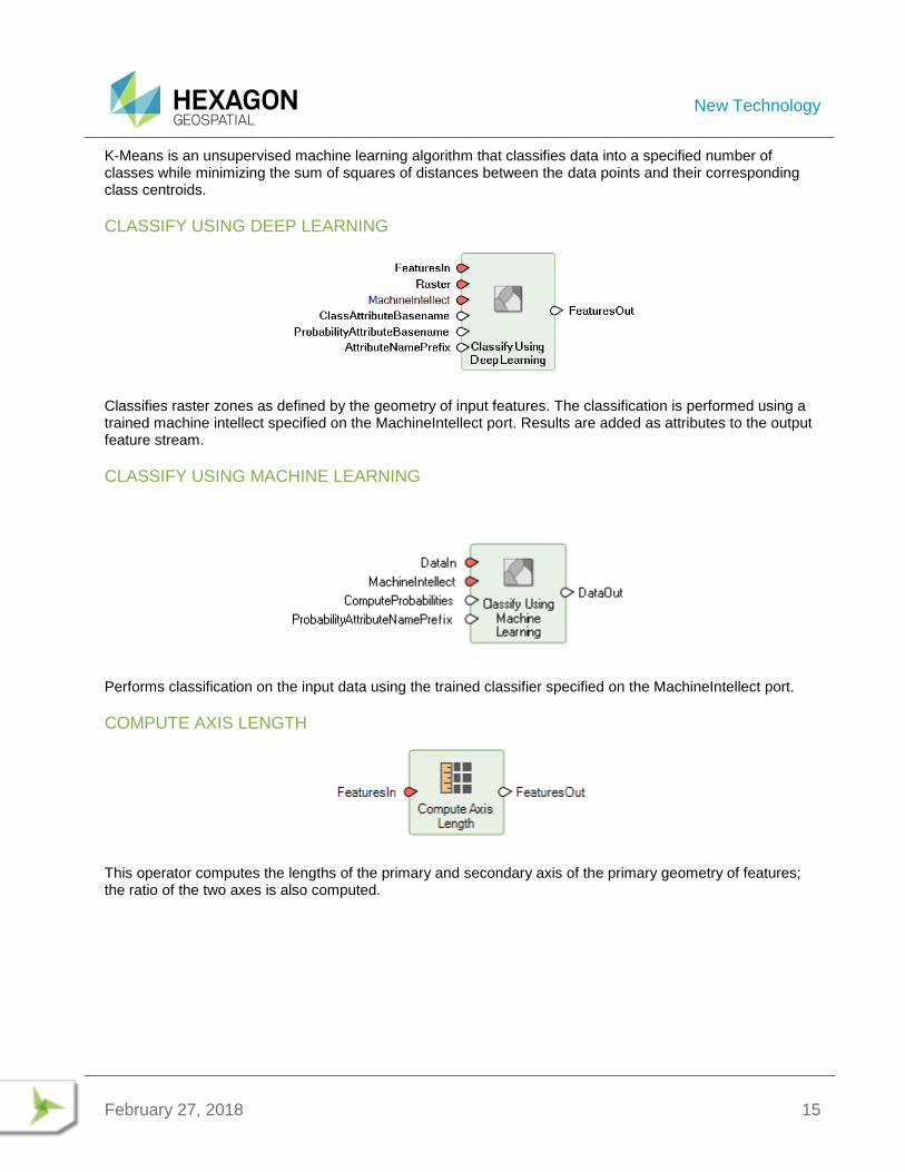
CLASSIFY USING DEEP LEARNING
Classifies raster zones as defined by the geometry of input features. The classification is performed using a trained machine intellect specified on the MachineIntellect port. Results are added as attributes to the output feature stream.
CLASSIFY USING MACHINE LEARNING
Performs classification on the input data using the trained classifier specified on the MachineIntellect port.
COMPUTE AXIS LENGTH
This operator computes the lengths of the primary and secondary axis of the primary geometry of features; the ratio of the two axes is also computed.
New Technology
February 27, 2018 16
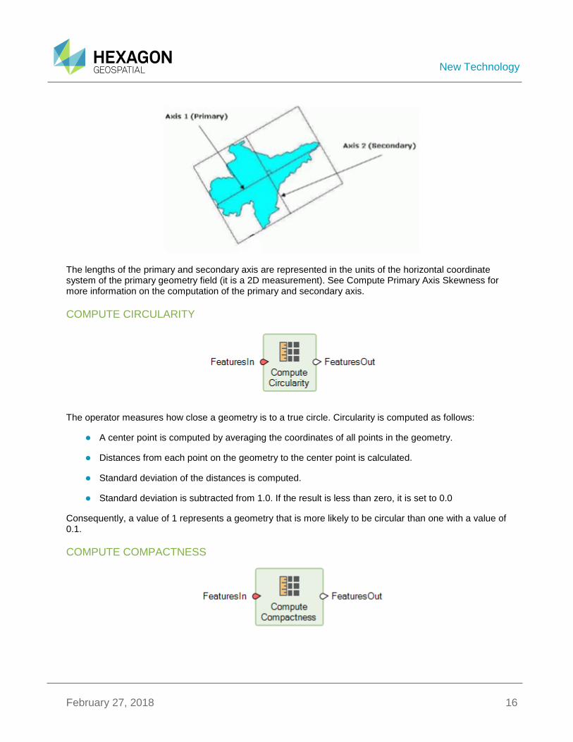
The lengths of the primary and secondary axis are represented in the units of the horizontal coordinate system of the primary geometry field (it is a 2D measurement). See Compute Primary Axis Skewness for more information on the computation of the primary and secondary axis.
COMPUTE CIRCULARITY
The operator measures how close a geometry is to a true circle. Circularity is computed as follows:
A center point is computed by averaging the coordinates of all points in the geometry.
Distances from each point on the geometry to the center point is calculated.
Standard deviation of the distances is computed.
Standard deviation is subtracted from 1.0. If the result is less than zero, it is set to 0.0
Consequently, a value of 1 represents a geometry that is more likely to be circular than one with a value of 0.1.
COMPUTE COMPACTNESS
New Technology
February 27, 2018 17
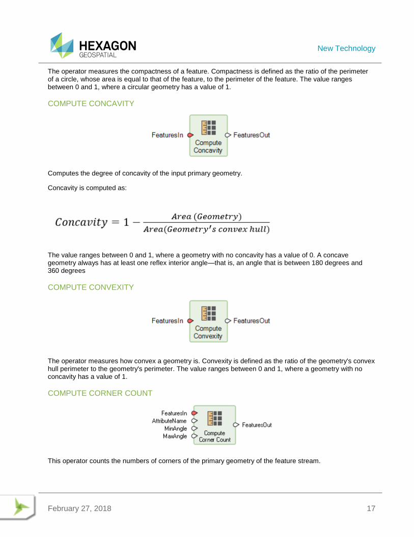
The operator measures the compactness of a feature. Compactness is defined as the ratio of the perimeter of a circle, whose area is equal to that of the feature, to the perimeter of the feature. The value ranges between 0 and 1, where a circular geometry has a value of 1.
COMPUTE CONCAVITY
Computes the degree of concavity of the input primary geometry.
Concavity is computed as:
The value ranges between 0 and 1, where a geometry with no concavity has a value of 0. A concave geometry always has at least one reflex interior angle—that is, an angle that is between 180 degrees and 360 degrees
COMPUTE CONVEXITY
The operator measures how convex a geometry is. Convexity is defined as the ratio of the geometry's convex hull perimeter to the geometry's perimeter. The value ranges between 0 and 1, where a geometry with no concavity has a value of 1.
COMPUTE CORNER COUNT
This operator counts the numbers of corners of the primary geometry of the feature stream.
New Technology
February 27, 2018 18
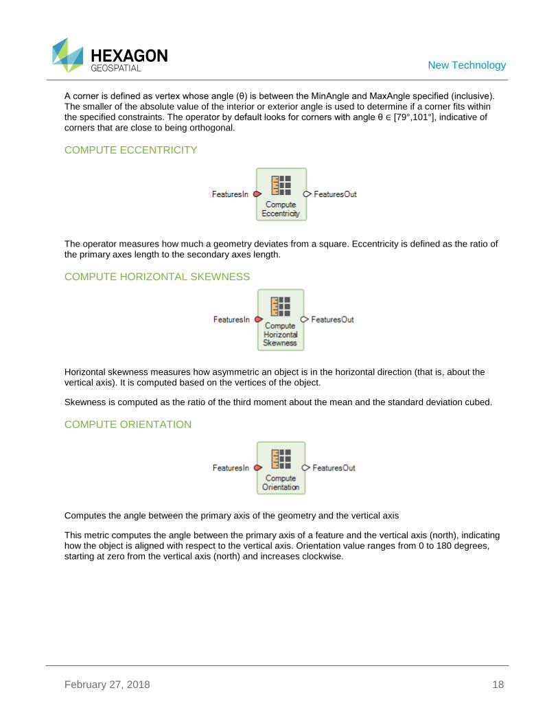
A corner is defined as vertex whose angle (θ) is between the MinAngle and MaxAngle specified (inclusive). The smaller of the absolute value of the interior or exterior angle is used to determine if a corner fits within the specified constraints. The operator by default looks for corners with angle θ ∈ [79°,101°], indicative of corners that are close to being orthogonal.
COMPUTE ECCENTRICITY
The operator measures how much a geometry deviates from a square. Eccentricity is defined as the ratio of the primary axes length to the secondary axes length.
COMPUTE HORIZONTAL SKEWNESS
Horizontal skewness measures how asymmetric an object is in the horizontal direction (that is, about the vertical axis). It is computed based on the vertices of the object.
Skewness is computed as the ratio of the third moment about the mean and the standard deviation cubed.
COMPUTE ORIENTATION
Computes the angle between the primary axis of the geometry and the vertical axis
This metric computes the angle between the primary axis of a feature and the vertical axis (north), indicating how the object is aligned with respect to the vertical axis. Orientation value ranges from 0 to 180 degrees, starting at zero from the vertical axis (north) and increases clockwise.
New Technology
February 27, 2018 19
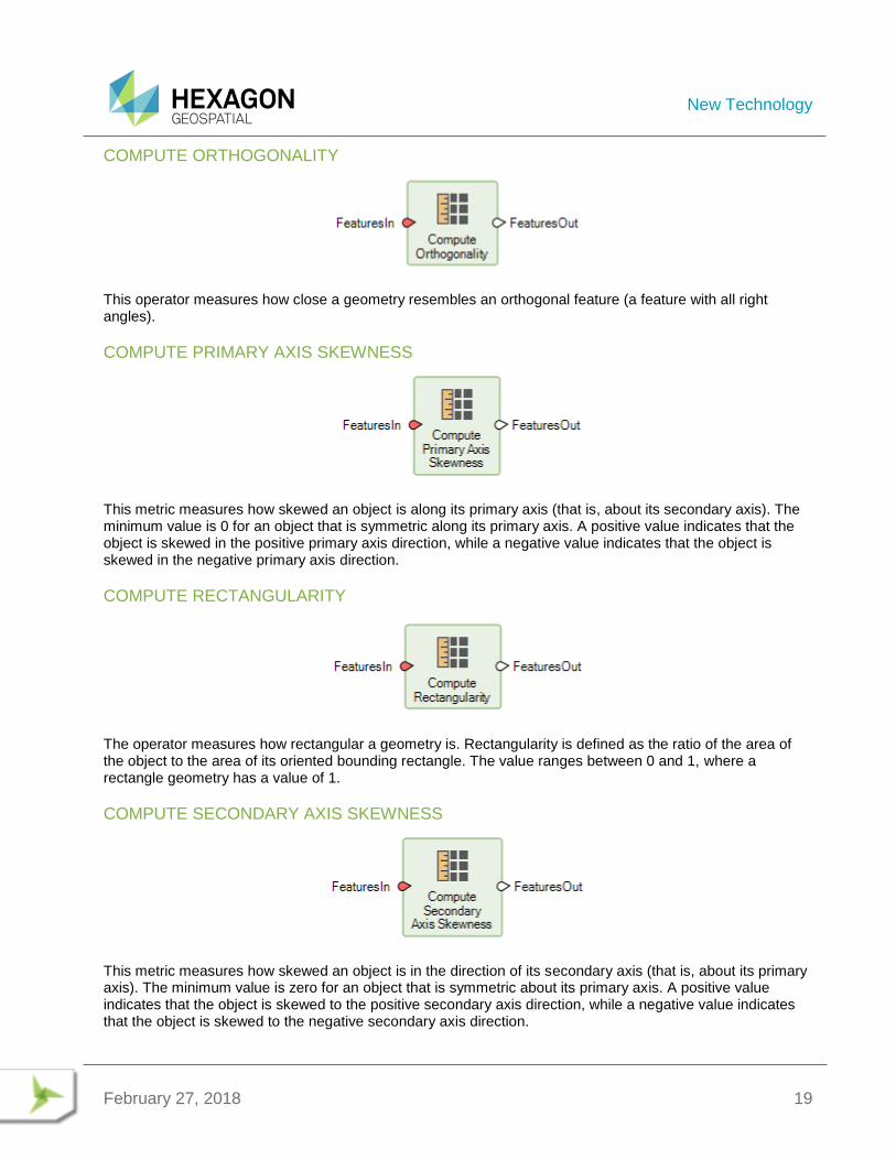
COMPUTE ORTHOGONALITY
This operator measures how close a geometry resembles an orthogonal feature (a feature with all right angles).
COMPUTE PRIMARY AXIS SKEWNESS
This metric measures how skewed an object is along its primary axis (that is, about its secondary axis). The minimum value is 0 for an object that is symmetric along its primary axis. A positive value indicates that the object is skewed in the positive primary axis direction, while a negative value indicates that the object is skewed in the negative primary axis direction.
COMPUTE RECTANGULARITY
The operator measures how rectangular a geometry is. Rectangularity is defined as the ratio of the area of the object to the area of its oriented bounding rectangle. The value ranges between 0 and 1, where a rectangle geometry has a value of 1.
COMPUTE SECONDARY AXIS SKEWNESS
This metric measures how skewed an object is in the direction of its secondary axis (that is, about its primary axis). The minimum value is zero for an object that is symmetric about its primary axis. A positive value indicates that the object is skewed to the positive secondary axis direction, while a negative value indicates that the object is skewed to the negative secondary axis direction.
New Technology
February 27, 2018 20
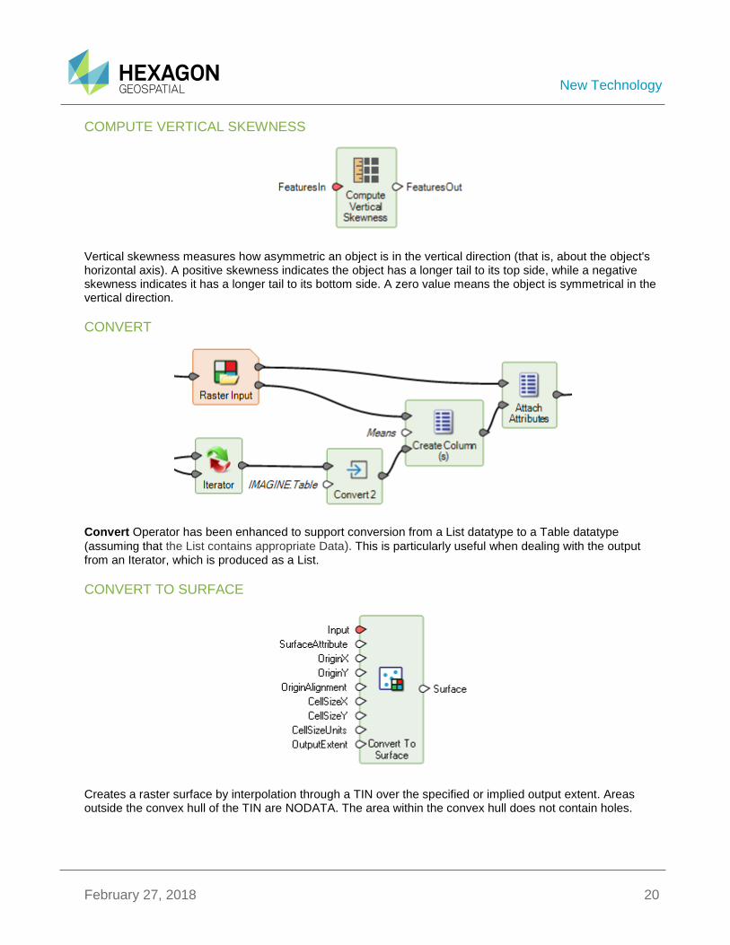
COMPUTE VERTICAL SKEWNESS
Vertical skewness measures how asymmetric an object is in the vertical direction (that is, about the object's horizontal axis). A positive skewness indicates the object has a longer tail to its top side, while a negative skewness indicates it has a longer tail to its bottom side. A zero value means the object is symmetrical in the vertical direction.
CONVERT
Convert Operator has been enhanced to support conversion from a List datatype to a Table datatype
(assuming that the List contains appropriate Data). This is particularly useful when dealing with the output from an Iterator, which is produced as a List.
CONVERT TO SURFACE
Creates a raster surface by interpolation through a TIN over the specified or implied output extent. Areas outside the convex hull of the TIN are NODATA. The area within the convex hull does not contain holes.

New Technology
February 27, 2018 21
CREATE BOUNDING BOX
Create the coordinate-system-axis-aligned bounding box of the primary geometry of the input features. This geometry is added as the primary geometry and the original geometry is retained in the output features.
CREATE CENTERLINE
This operator creates a single center line from the primary geometry of the input features. The center line is added as the primary geometry and the original geometry is retained in the output features.
CREATE CENTERPOINT
Create Centerpoint operator creates a center point within a geometry. A centerpoint differs from a centroid in that it is guaranteed to fall in the interior of the geometry, however there is no one correct centerpoint location. If the need is for a true centroid (center of gravity), use the Create Centroid operator.
New Technology
February 27, 2018 22
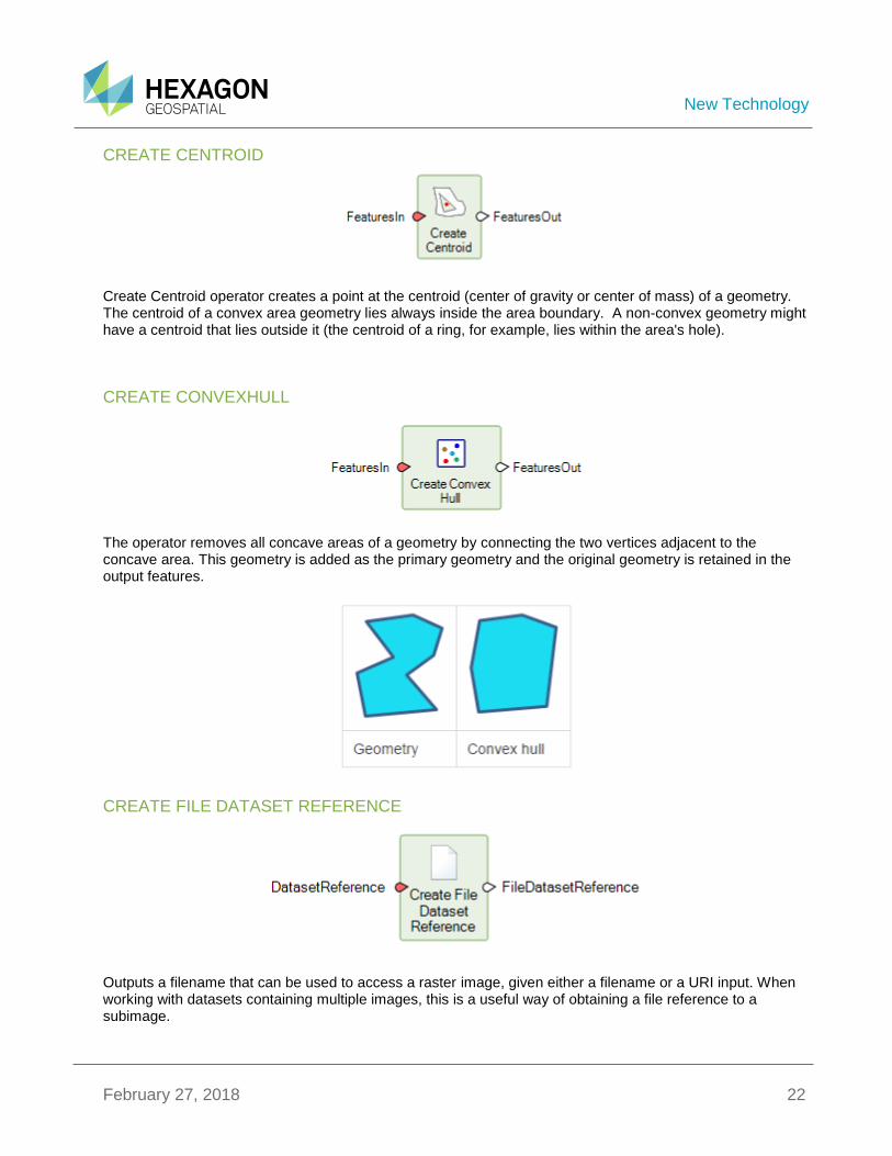
CREATE CENTROID
Create Centroid operator creates a point at the centroid (center of gravity or center of mass) of a geometry. The centroid of a convex area geometry lies always inside the area boundary. A non-convex geometry might have a centroid that lies outside it (the centroid of a ring, for example, lies within the area's hole).
CREATE CONVEXHULL
The operator removes all concave areas of a geometry by connecting the two vertices adjacent to the concave area. This geometry is added as the primary geometry and the original geometry is retained in the output features.
CREATE FILE DATASET REFERENCE
Outputs a filename that can be used to access a raster image, given either a filename or a URI input. When working with datasets containing multiple images, this is a useful way of obtaining a file reference to a subimage.
New Technology
February 27, 2018 23
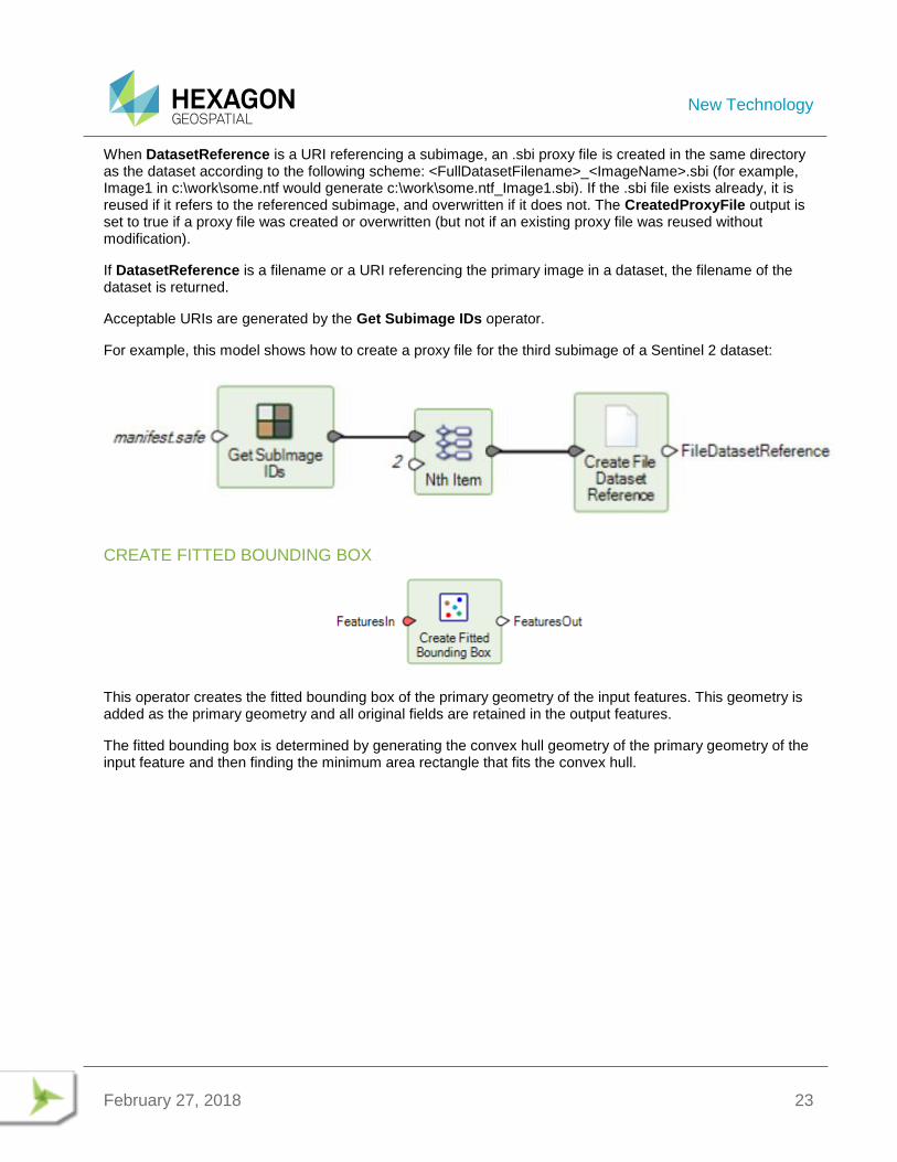
When DatasetReference is a URI referencing a subimage, an .sbi proxy file is created in the same directory as the dataset according to the following scheme: <FullDatasetFilename>_<ImageName>.sbi (for example, Image1 in c:\work\some.ntf would generate c:\work\some.ntf_Image1.sbi). If the .sbi file exists already, it is reused if it refers to the referenced subimage, and overwritten if it does not. The CreatedProxyFile output is set to true if a proxy file was created or overwritten (but not if an existing proxy file was reused without modification).
If DatasetReference is a filename or a URI referencing the primary image in a dataset, the filename of the dataset is returned.
Acceptable URIs are generated by the Get Subimage IDs operator.
For example, this model shows how to create a proxy file for the third subimage of a Sentinel 2 dataset:
CREATE FITTED BOUNDING BOX
This operator creates the fitted bounding box of the primary geometry of the input features. This geometry is added as the primary geometry and all original fields are retained in the output features.
The fitted bounding box is determined by generating the convex hull geometry of the primary geometry of the input feature and then finding the minimum area rectangle that fits the convex hull.
New Technology
February 27, 2018 24
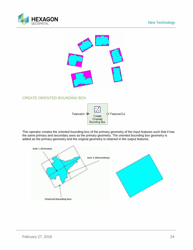
CREATE ORIENTED BOUNDING BOX
This operator creates the oriented bounding box of the primary geometry of the input features such that it has the same primary and secondary axes as the primary geometry. The oriented bounding box geometry is added as the primary geometry and the original geometry is retained in the output features.
New Technology
February 27, 2018 25
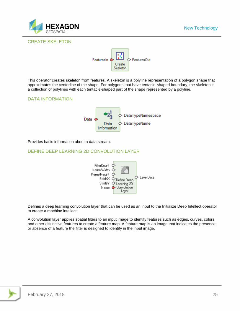
CREATE SKELETON
This operator creates skeleton from features. A skeleton is a polyline representation of a polygon shape that approximates the centerline of the shape. For polygons that have tentacle-shaped boundary, the skeleton is a collection of polylines with each tentacle-shaped part of the shape represented by a polyline.
DATA INFORMATION
Provides basic information about a data stream.
DEFINE DEEP LEARNING 2D CONVOLUTION LAYER
Defines a deep learning convolution layer that can be used as an input to the Initialize Deep Intellect operator to create a machine intellect.
A convolution layer applies spatial filters to an input image to identify features such as edges, curves, colors and other distinctive features to create a feature map. A feature map is an image that indicates the presence or absence of a feature the filter is designed to identify in the input image.
New Technology
February 27, 2018 26
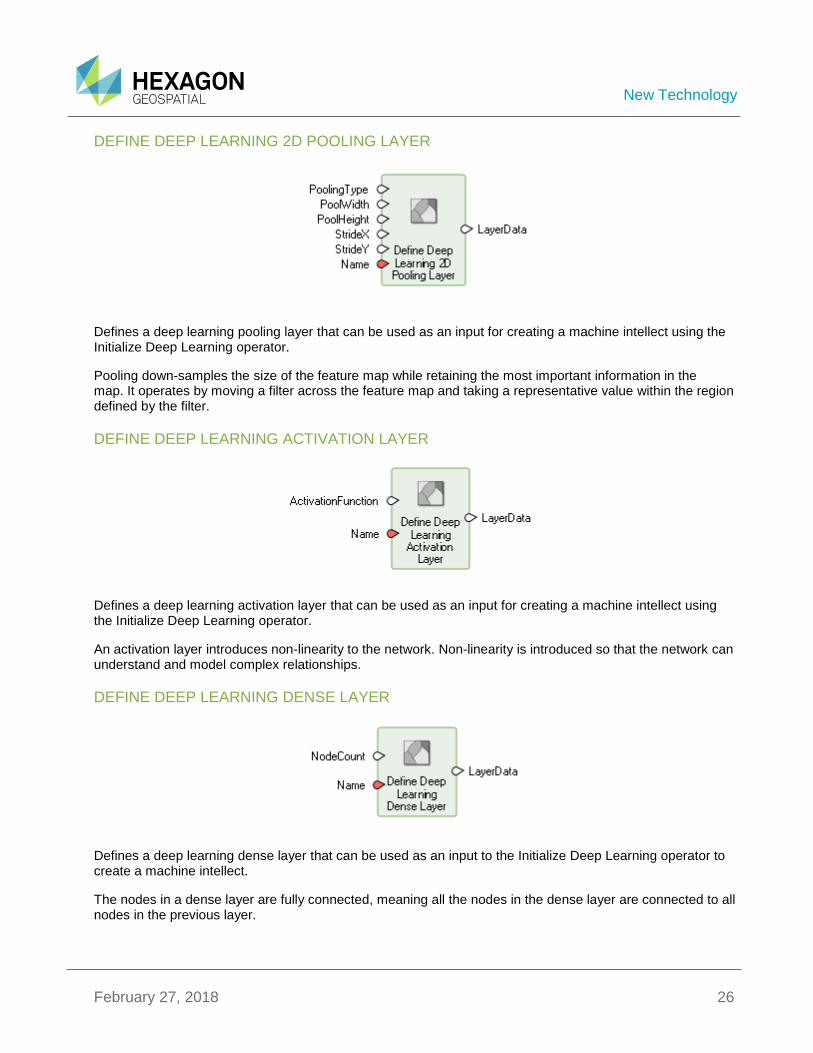
DEFINE DEEP LEARNING 2D POOLING LAYER
Defines a deep learning pooling layer that can be used as an input for creating a machine intellect using the Initialize Deep Learning operator.
Pooling down-samples the size of the feature map while retaining the most important information in the map. It operates by moving a filter across the feature map and taking a representative value within the region defined by the filter.
DEFINE DEEP LEARNING ACTIVATION LAYER
Defines a deep learning activation layer that can be used as an input for creating a machine intellect using the Initialize Deep Learning operator.
An activation layer introduces non-linearity to the network. Non-linearity is introduced so that the network can understand and model complex relationships.
DEFINE DEEP LEARNING DENSE LAYER
Defines a deep learning dense layer that can be used as an input to the Initialize Deep Learning operator to create a machine intellect.
The nodes in a dense layer are fully connected, meaning all the nodes in the dense layer are connected to all nodes in the previous layer.
New Technology
February 27, 2018 27
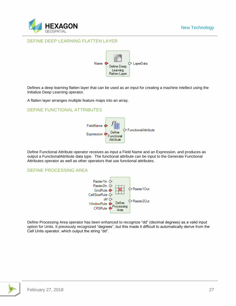
DEFINE DEEP LEARNING FLATTEN LAYER
Defines a deep learning flatten layer that can be used as an input for creating a machine intellect using the Initialize Deep Learning operator.
A flatten layer arranges multiple feature maps into an array.
DEFINE FUNCTIONAL ATTRIBUTES
Define Functional Attribute operator receives as input a Field Name and an Expression, and produces as output a FunctionalAttribute data type. The functional attribute can be input to the Generate Functional Attributes operator as well as other operators that use functional attributes.
DEFINE PROCESSING AREA
Define Processing Area operator has been enhanced to recognize “dd” (decimal degrees) as a valid input option for Units. It previously recognized “degrees”, but this made it difficult to automatically derive from the Cell Units operator, which output the string “dd”.
New Technology
February 27, 2018 28
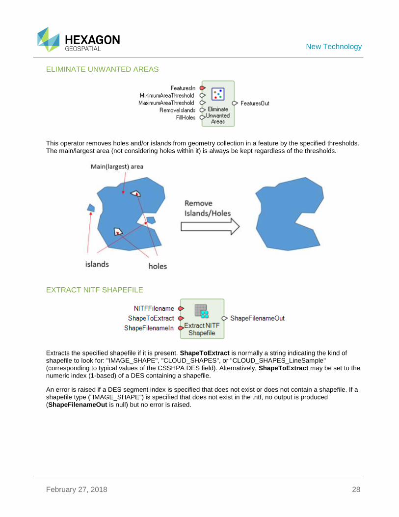
ELIMINATE UNWANTED AREAS
This operator removes holes and/or islands from geometry collection in a feature by the specified thresholds. The main/largest area (not considering holes within it) is always be kept regardless of the thresholds.
EXTRACT NITF SHAPEFILE
Extracts the specified shapefile if it is present. ShapeToExtract is normally a string indicating the kind of shapefile to look for: "IMAGE_SHAPE", "CLOUD_SHAPES", or "CLOUD_SHAPES_LineSample" (corresponding to typical values of the CSSHPA DES field). Alternatively, ShapeToExtract may be set to the numeric index (1-based) of a DES containing a shapefile.
An error is raised if a DES segment index is specified that does not exist or does not contain a shapefile. If a shapefile type ("IMAGE_SHAPE") is specified that does not exist in the .ntf, no output is produced (ShapeFilenameOut is null) but no error is raised.
New Technology
February 27, 2018 29
FIND ITEM
The operator compares the item to the content of the list and returns the indices of all the occurrences. The type of the comparison item must match the type of the elements in the list. An empty list is returned if no matches are found.
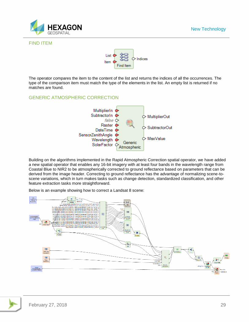
GENERIC ATMOSPHERIC CORRECTION
Building on the algorithms implemented in the Rapid Atmospheric Correction spatial operator, we have added a new spatial operator that enables any 16-bit imagery with at least four bands in the wavelength range from Coastal Blue to NIR2 to be atmospherically corrected to ground reflectance based on parameters that can be derived from the image header. Correcting to ground reflectance has the advantage of normalizing scene-to-scene variations, which in turn makes tasks such as change detection, standardized classification, and other feature extraction tasks more straightforward.
Below is an example showing how to correct a Landsat 8 scene:
New Technology
February 27, 2018 30
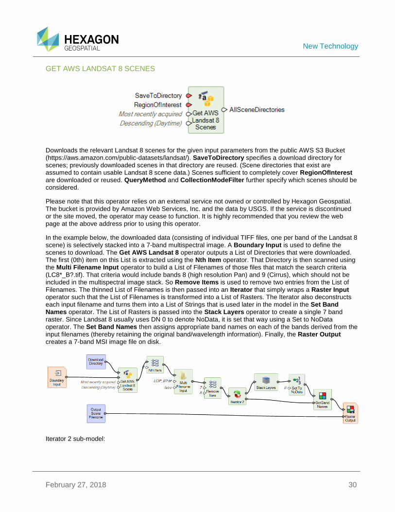
GET AWS LANDSAT 8 SCENES
Downloads the relevant Landsat 8 scenes for the given input parameters from the public AWS S3 Bucket (https://aws.amazon.com/public-datasets/landsat/). SaveToDirectory specifies a download directory for scenes; previously downloaded scenes in that directory are reused. (Scene directories that exist are assumed to contain usable Landsat 8 scene data.) Scenes sufficient to completely cover RegionOfInterest are downloaded or reused. QueryMethod and CollectionModeFilter further specify which scenes should be considered.
Please note that this operator relies on an external service not owned or controlled by Hexagon Geospatial. The bucket is provided by Amazon Web Services, Inc. and the data by USGS. If the service is discontinued or the site moved, the operator may cease to function. It is highly recommended that you review the web page at the above address prior to using this operator.
In the example below, the downloaded data (consisting of individual TIFF files, one per band of the Landsat 8 scene) is selectively stacked into a 7-band multispectral image. A Boundary Input is used to define the scenes to download. The Get AWS Landsat 8 operator outputs a List of Directories that were downloaded. The first (0th) item on this List is extracted using the Nth Item operator. That Directory is then scanned using the Multi Filename Input operator to build a List of Filenames of those files that match the search criteria (LC8*_B?.tif). That criteria would include bands 8 (high resolution Pan) and 9 (Cirrus), which should not be included in the multispectral image stack. So Remove Items is used to remove two entries from the List of Filenames. The thinned List of Filenames is then passed into an Iterator that simply wraps a Raster Input operator such that the List of Filenames is transformed into a List of Rasters. The Iterator also deconstructs each input filename and turns them into a List of Strings that is used later in the model in the Set Band Names operator. The List of Rasters is passed into the Stack Layers operator to create a single 7 band raster. Since Landsat 8 usually uses DN 0 to denote NoData, it is set that way using a Set to NoData operator. The Set Band Names then assigns appropriate band names on each of the bands derived from the input filenames (thereby retaining the original band/wavelength information). Finally, the Raster Output creates a 7-band MSI image file on disk.
Iterator 2 sub-model:
New Technology
February 27, 2018 31
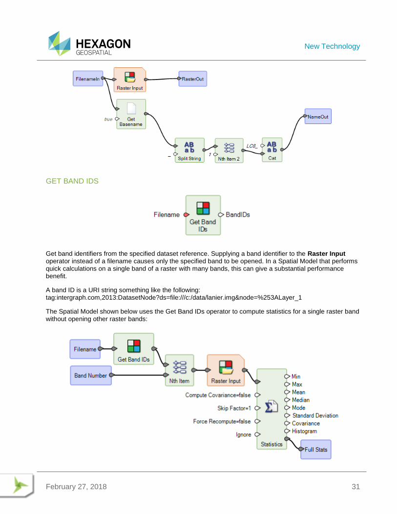
GET BAND IDS
Get band identifiers from the specified dataset reference. Supplying a band identifier to the Raster Input operator instead of a filename causes only the specified band to be opened. In a Spatial Model that performs quick calculations on a single band of a raster with many bands, this can give a substantial performance benefit.
A band ID is a URI string something like the following: tag:intergraph.com,2013:DatasetNode?ds=file:///c:/data/lanier.img&node=%253ALayer_1
The Spatial Model shown below uses the Get Band IDs operator to compute statistics for a single raster band without opening other raster bands:
New Technology
February 27, 2018 32
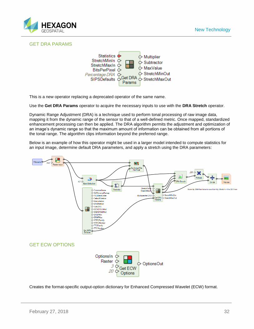
GET DRA PARAMS
This is a new operator replacing a deprecated operator of the same name.
Use the Get DRA Params operator to acquire the necessary inputs to use with the DRA Stretch operator.
Dynamic Range Adjustment (DRA) is a technique used to perform tonal processing of raw image data, mapping it from the dynamic range of the sensor to that of a well-defined metric. Once mapped, standardized enhancement processing can then be applied. The DRA algorithm permits the adjustment and optimization of an image’s dynamic range so that the maximum amount of information can be obtained from all portions of the tonal range. The algorithm clips information beyond the preferred range.
Below is an example of how this operator might be used in a larger model intended to compute statistics for an input image, determine default DRA parameters, and apply a stretch using the DRA parameters:
GET ECW OPTIONS
Creates the format-specific output-option dictionary for Enhanced Compressed Wavelet (ECW) format.
New Technology
February 27, 2018 33
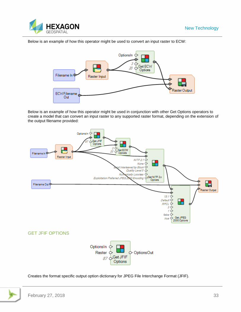
Below is an example of how this operator might be used to convert an input raster to ECW:
Below is an example of how this operator might be used in conjunction with other Get Options operators to create a model that can convert an input raster to any supported raster format, depending on the extension of the output filename provided:
GET JFIF OPTIONS
Creates the format specific output option dictionary for JPEG File Interchange Format (JFIF).
New Technology
February 27, 2018 34
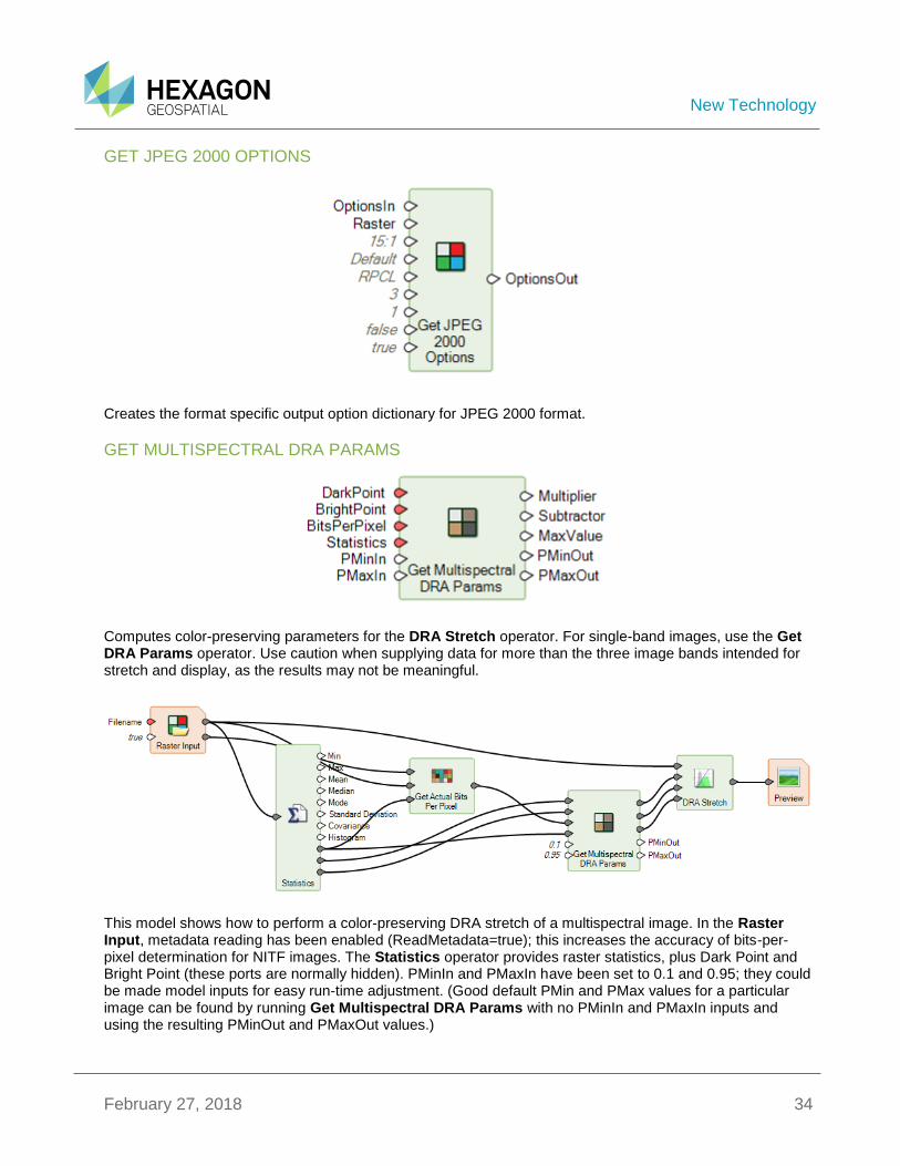
GET JPEG 2000 OPTIONS
Creates the format specific output option dictionary for JPEG 2000 format.
GET MULTISPECTRAL DRA PARAMS
Computes color-preserving parameters for the DRA Stretch operator. For single-band images, use the Get DRA Params operator. Use caution when supplying data for more than the three image bands intended for stretch and display, as the results may not be meaningful.
This model shows how to perform a color-preserving DRA stretch of a multispectral image. In the Raster Input, metadata reading has been enabled (ReadMetadata=true); this increases the accuracy of bits-per-pixel determination for NITF images. The Statistics operator provides raster statistics, plus Dark Point and Bright Point (these ports are normally hidden). PMinIn and PMaxIn have been set to 0.1 and 0.95; they could be made model inputs for easy run-time adjustment. (Good default PMin and PMax values for a particular image can be found by running Get Multispectral DRA Params with no PMinIn and PMaxIn inputs and using the resulting PMinOut and PMaxOut values.)
New Technology
February 27, 2018 35
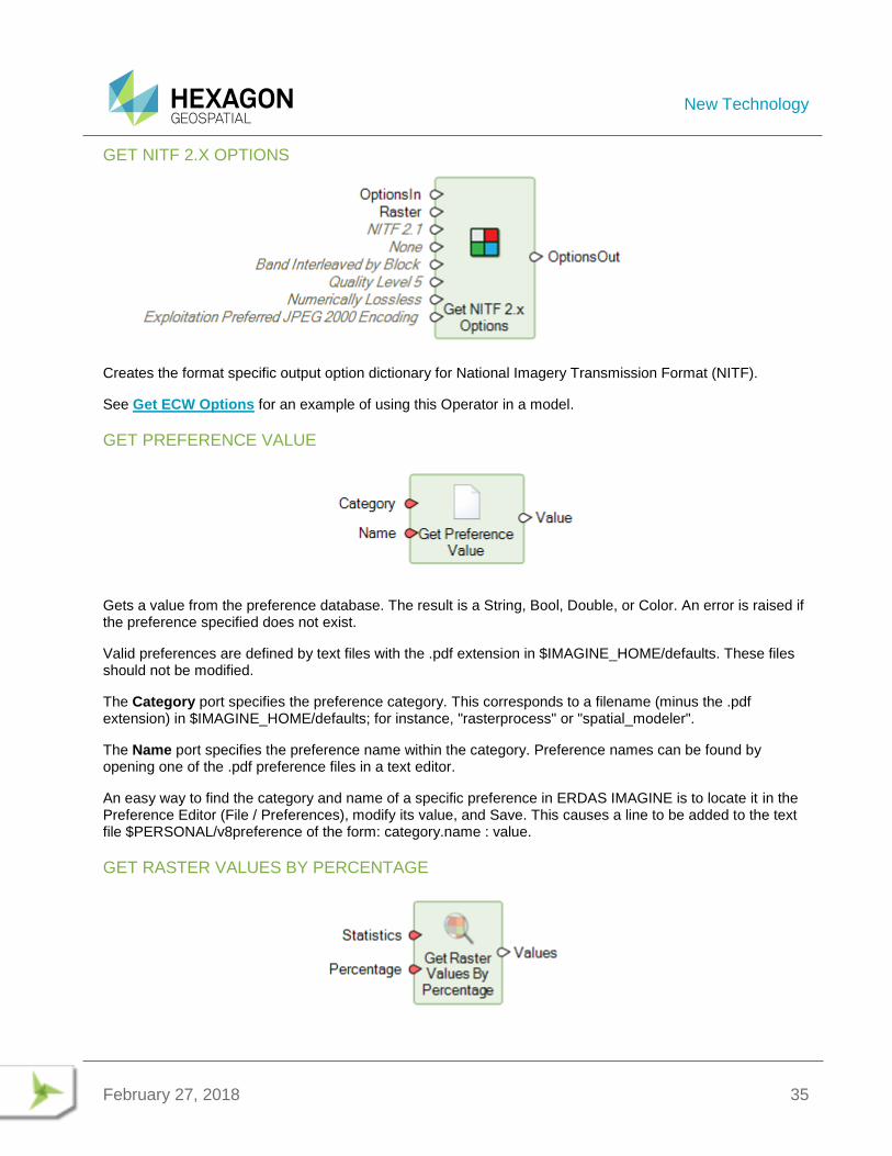
GET NITF 2.X OPTIONS
Creates the format specific output option dictionary for National Imagery Transmission Format (NITF).
See Get ECW Options for an example of using this Operator in a model.
GET PREFERENCE VALUE
Gets a value from the preference database. The result is a String, Bool, Double, or Color. An error is raised if the preference specified does not exist.
Valid preferences are defined by text files with the .pdf extension in $IMAGINE_HOME/defaults. These files should not be modified.
The Category port specifies the preference category. This corresponds to a filename (minus the .pdf extension) in $IMAGINE_HOME/defaults; for instance, "rasterprocess" or "spatial_modeler".
The Name port specifies the preference name within the category. Preference names can be found by opening one of the .pdf preference files in a text editor.
An easy way to find the category and name of a specific preference in ERDAS IMAGINE is to locate it in the Preference Editor (File / Preferences), modify its value, and Save. This causes a line to be added to the text file $PERSONAL/v8preference of the form: category.name : value.
GET RASTER VALUES BY PERCENTAGE
New Technology
February 27, 2018 36
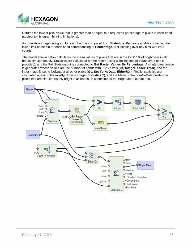
Returns the lowest pixel value that is greater than or equal to a requested percentage of pixels in each band (subject to histogram binning limitations).
A cumulative image histogram for each band is computed from Statistics. Values is a table containing the lower limit of the bin for each band corresponding to Percentage, first skipping over any bins with zero counts.
The model shown below calculates the mean values of pixels that are in the top 0.1% of brightness in all bands simultaneously. Statistics are calculated for the raster (using a limiting image boundary, if one is provided), and the Full Stats output is connected to Get Raster Values By Percentage. A single-band image is generated whose values are the number of bands with 0.1% pixels (Gt, Integer, Stack Total), and the input image is set to NoData at all other pixels (Ge, Set To NoData, Either/Or). Finally, statistics are calculated again on the mostly-NoData image (Statistics 2), and the Mean of the non-NoData pixels--the pixels that are simultaneously bright in all bands--is connected to the BrightMean output port.
New Technology
February 27, 2018 37
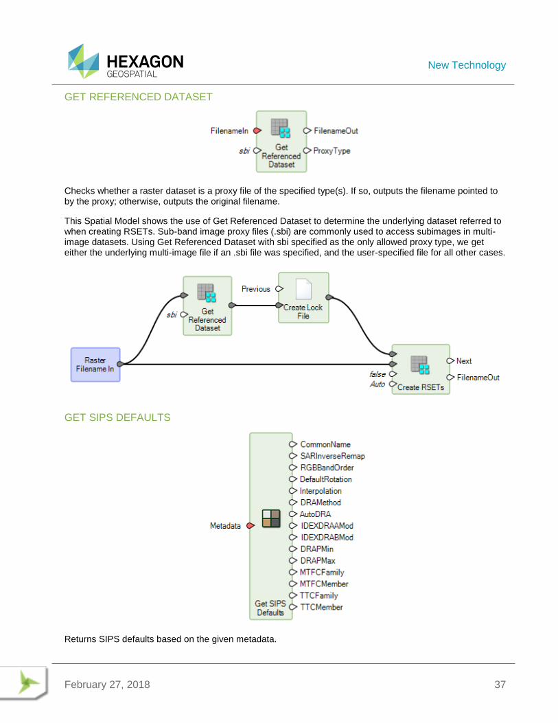
GET REFERENCED DATASET
Checks whether a raster dataset is a proxy file of the specified type(s). If so, outputs the filename pointed to by the proxy; otherwise, outputs the original filename.
This Spatial Model shows the use of Get Referenced Dataset to determine the underlying dataset referred to when creating RSETs. Sub-band image proxy files (.sbi) are commonly used to access subimages in multi-image datasets. Using Get Referenced Dataset with sbi specified as the only allowed proxy type, we get either the underlying multi-image file if an .sbi file was specified, and the user-specified file for all other cases.
GET SIPS DEFAULTS
Returns SIPS defaults based on the given metadata.
New Technology
February 27, 2018 38
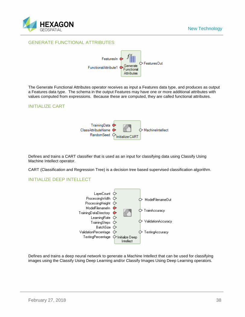
GENERATE FUNCTIONAL ATTRIBUTES
The Generate Functional Attributes operator receives as input a Features data type, and produces as output a Features data type. The schema in the output Features may have one or more additional attributes with values computed from expressions. Because these are computed, they are called functional attributes.
INITIALIZE CART
Defines and trains a CART classifier that is used as an input for classifying data using Classify Using Machine Intellect operator.
CART (Classification and Regression Tree) is a decision tree based supervised classification algorithm.
INITIALIZE DEEP INTELLECT
Defines and trains a deep neural network to generate a Machine Intellect that can be used for classifying images using the Classify Using Deep Learning and/or Classify Images Using Deep Learning operators.
New Technology
February 27, 2018 39
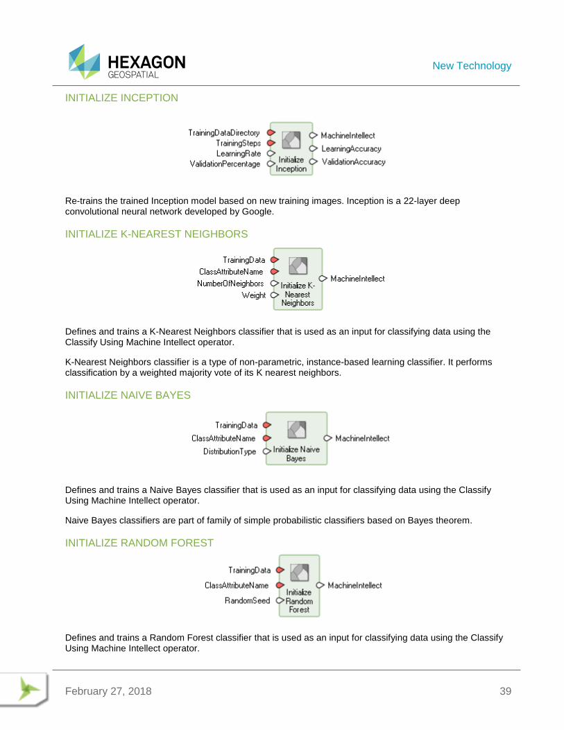
INITIALIZE INCEPTION
Re-trains the trained Inception model based on new training images. Inception is a 22-layer deep convolutional neural network developed by Google.
INITIALIZE K-NEAREST NEIGHBORS
Defines and trains a K-Nearest Neighbors classifier that is used as an input for classifying data using the Classify Using Machine Intellect operator.
K-Nearest Neighbors classifier is a type of non-parametric, instance-based learning classifier. It performs classification by a weighted majority vote of its K nearest neighbors.
INITIALIZE NAIVE BAYES
Defines and trains a Naive Bayes classifier that is used as an input for classifying data using the Classify Using Machine Intellect operator.
Naive Bayes classifiers are part of family of simple probabilistic classifiers based on Bayes theorem.
INITIALIZE RANDOM FOREST
Defines and trains a Random Forest classifier that is used as an input for classifying data using the Classify Using Machine Intellect operator.
New Technology
February 27, 2018 40
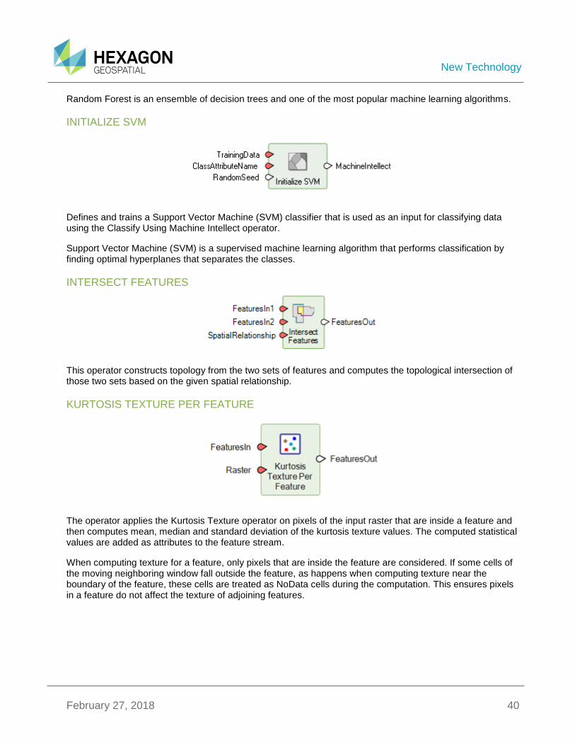
Random Forest is an ensemble of decision trees and one of the most popular machine learning algorithms.
INITIALIZE SVM
Defines and trains a Support Vector Machine (SVM) classifier that is used as an input for classifying data using the Classify Using Machine Intellect operator.
Support Vector Machine (SVM) is a supervised machine learning algorithm that performs classification by finding optimal hyperplanes that separates the classes.
INTERSECT FEATURES
This operator constructs topology from the two sets of features and computes the topological intersection of those two sets based on the given spatial relationship.
KURTOSIS TEXTURE PER FEATURE
The operator applies the Kurtosis Texture operator on pixels of the input raster that are inside a feature and then computes mean, median and standard deviation of the kurtosis texture values. The computed statistical values are added as attributes to the feature stream.
When computing texture for a feature, only pixels that are inside the feature are considered. If some cells of the moving neighboring window fall outside the feature, as happens when computing texture near the boundary of the feature, these cells are treated as NoData cells during the computation. This ensures pixels in a feature do not affect the texture of adjoining features.
New Technology
February 27, 2018 41
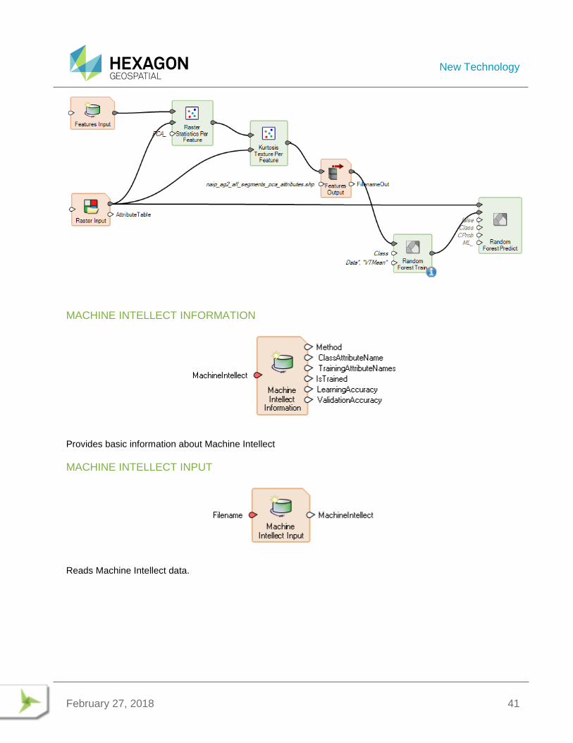
MACHINE INTELLECT INFORMATION
Provides basic information about Machine Intellect
MACHINE INTELLECT INPUT
Reads Machine Intellect data.
New Technology
February 27, 2018 42
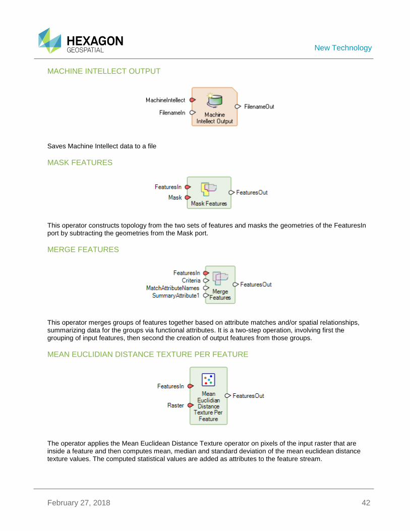
MACHINE INTELLECT OUTPUT
Saves Machine Intellect data to a file
MASK FEATURES
This operator constructs topology from the two sets of features and masks the geometries of the FeaturesIn port by subtracting the geometries from the Mask port.
MERGE FEATURES
This operator merges groups of features together based on attribute matches and/or spatial relationships, summarizing data for the groups via functional attributes. It is a two-step operation, involving first the grouping of input features, then second the creation of output features from those groups.
MEAN EUCLIDIAN DISTANCE TEXTURE PER FEATURE
The operator applies the Mean Euclidean Distance Texture operator on pixels of the input raster that are inside a feature and then computes mean, median and standard deviation of the mean euclidean distance texture values. The computed statistical values are added as attributes to the feature stream.
New Technology
February 27, 2018 43
When computing texture for a feature, only pixels that are inside the feature are considered. If some cells of the moving neighboring window fall outside the feature, as happens when computing texture near the boundary of the feature, these cells are treated as NoData cells during the computation. This ensures pixels in a feature do not affect the texture of adjoining features.
The attribute names for the output feature stream are constructed based on AttributeNamePrefix, AttributeBasename for the statistics being computed and the number of bands of the raster. If the constructed attribute name matches with the name of an existing field and the field type is appropriate, the existing field is overwritten. Otherwise, the operation fails.
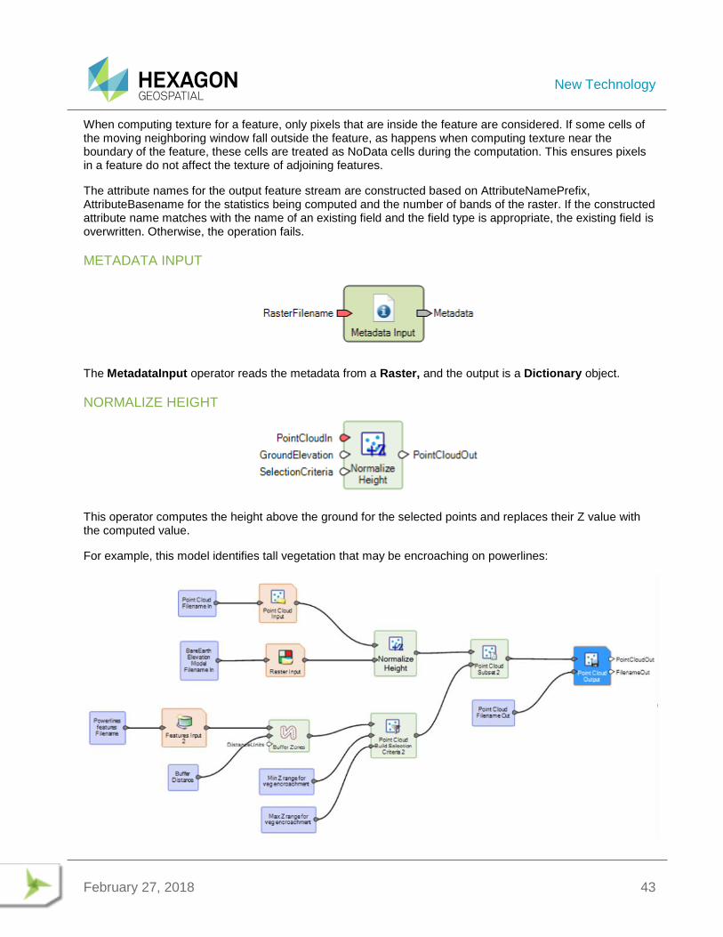
METADATA INPUT
The MetadataInput operator reads the metadata from a Raster, and the output is a Dictionary object.
NORMALIZE HEIGHT
This operator computes the height above the ground for the selected points and replaces their Z value with the computed value.
For example, this model identifies tall vegetation that may be encroaching on powerlines:
New Technology
February 27, 2018 44
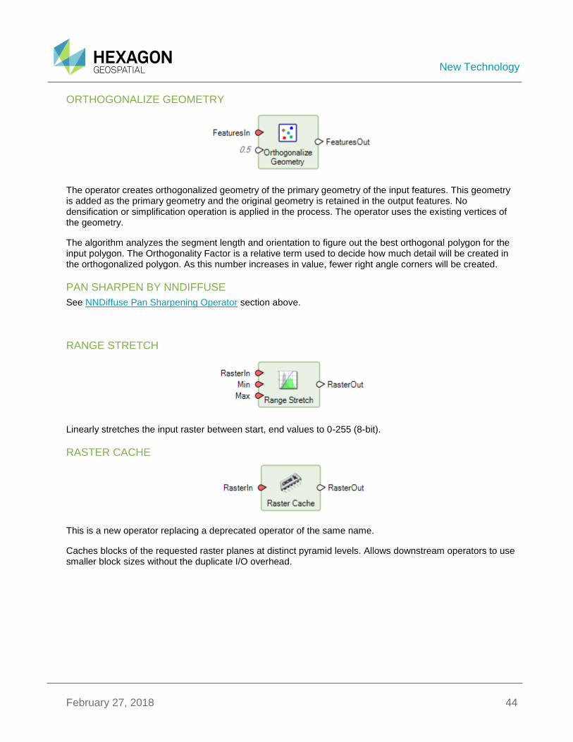
ORTHOGONALIZE GEOMETRY
The operator creates orthogonalized geometry of the primary geometry of the input features. This geometry is added as the primary geometry and the original geometry is retained in the output features. No densification or simplification operation is applied in the process. The operator uses the existing vertices of the geometry.
The algorithm analyzes the segment length and orientation to figure out the best orthogonal polygon for the input polygon. The Orthogonality Factor is a relative term used to decide how much detail will be created in the orthogonalized polygon. As this number increases in value, fewer right angle corners will be created.
PAN SHARPEN BY NNDIFFUSE
See NNDiffuse Pan Sharpening Operator section above.
RANGE STRETCH
Linearly stretches the input raster between start, end values to 0-255 (8-bit).
RASTER CACHE
This is a new operator replacing a deprecated operator of the same name.
Caches blocks of the requested raster planes at distinct pyramid levels. Allows downstream operators to use smaller block sizes without the duplicate I/O overhead.

New Technology
February 27, 2018 45
RASTER STATISTICS PER FEATURE
This operator computes statistics on pixels of the input raster that are inside a feature. The computed statistical values are added as attributes to the feature stream. By default, mean is computed. Other statistical values (Standard Deviation, Minimum, Maximum, etc) can be calculated by turning on their appropriate ports.
This is a particularly useful Operator for creating information for Machine Learning models.
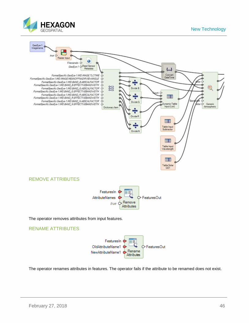
READ SENSOR METADATA
Reads vendor-supplied metadata files associated with a raster dataset. If a metadata file is found, its full contents are added to the Metadata object in the Format Specific region; additionally, common schema fields in the Metadata object may be updated.
In the Spatial Model Editor, double-click on the SensorIn port to show a list of available metadata parsers. Setting SensorIn to one of these values causes only the corresponding parser to be used. If no sensor is specified, available parsers are tried until one succeeds.
Below is an example of a portion of a model that uses the Read Sensor Metadata operator to get read information from the vendor-supplied metadata files associated with the input raster dataset to compute the parameters to be used in the Generic Atmospheric operator.
New Technology
February 27, 2018 46
REMOVE ATTRIBUTES
The operator removes attributes from input features.
RENAME ATTRIBUTES
The operator renames attributes in features. The operator fails if the attribute to be renamed does not exist.
New Technology
February 27, 2018 47
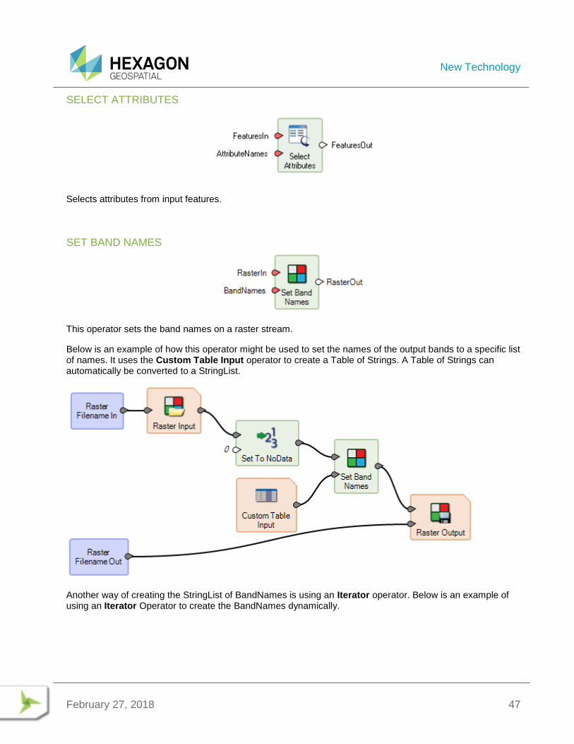
SELECT ATTRIBUTES
Selects attributes from input features.
SET BAND NAMES
This operator sets the band names on a raster stream.
Below is an example of how this operator might be used to set the names of the output bands to a specific list of names. It uses the Custom Table Input operator to create a Table of Strings. A Table of Strings can automatically be converted to a StringList.
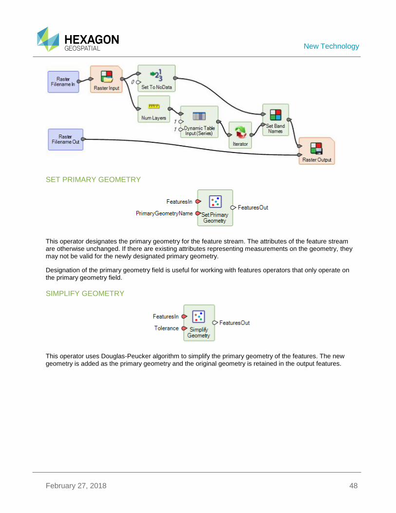
Another way of creating the StringList of BandNames is using an Iterator operator. Below is an example of using an Iterator Operator to create the BandNames dynamically.
New Technology
February 27, 2018 48
SET PRIMARY GEOMETRY
This operator designates the primary geometry for the feature stream. The attributes of the feature stream are otherwise unchanged. If there are existing attributes representing measurements on the geometry, they may not be valid for the newly designated primary geometry.
Designation of the primary geometry field is useful for working with features operators that only operate on the primary geometry field.
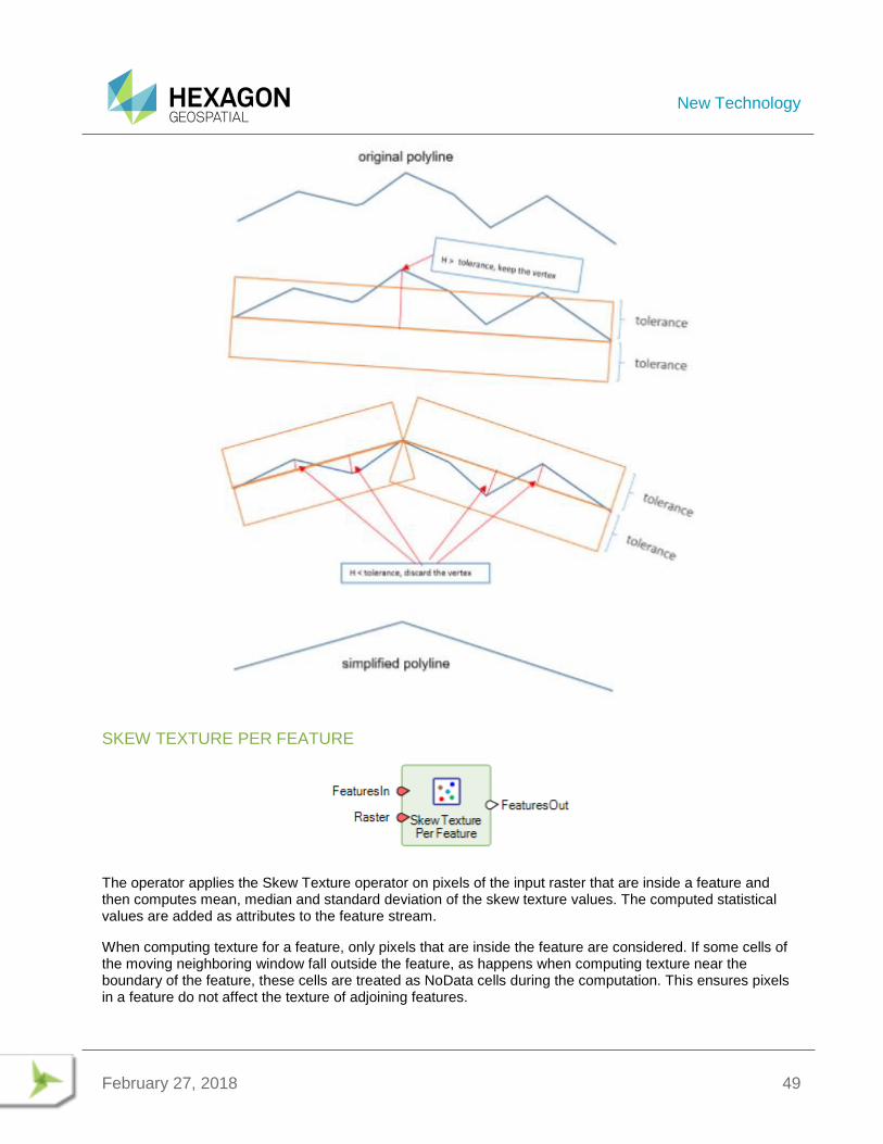
SIMPLIFY GEOMETRY
This operator uses Douglas-Peucker algorithm to simplify the primary geometry of the features. The new geometry is added as the primary geometry and the original geometry is retained in the output features.
New Technology
February 27, 2018 49
SKEW TEXTURE PER FEATURE
The operator applies the Skew Texture operator on pixels of the input raster that are inside a feature and then computes mean, median and standard deviation of the skew texture values. The computed statistical values are added as attributes to the feature stream.
When computing texture for a feature, only pixels that are inside the feature are considered. If some cells of the moving neighboring window fall outside the feature, as happens when computing texture near the boundary of the feature, these cells are treated as NoData cells during the computation. This ensures pixels in a feature do not affect the texture of adjoining features.
New Technology
February 27, 2018 50
The attribute names for the output feature stream are constructed based on AttributeNamePrefix, AttributeBasename for the statistics being computed and the number of bands of the raster. If the constructed attribute name matches with the name of an existing field and the field type is appropriate, the existing field is overwritten. otherwise, the operation fails.
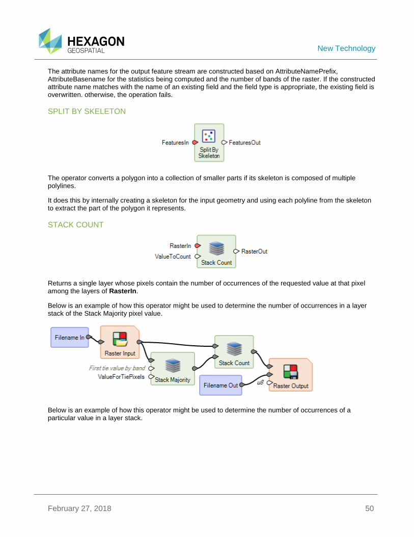
SPLIT BY SKELETON
The operator converts a polygon into a collection of smaller parts if its skeleton is composed of multiple polylines.
It does this by internally creating a skeleton for the input geometry and using each polyline from the skeleton to extract the part of the polygon it represents.
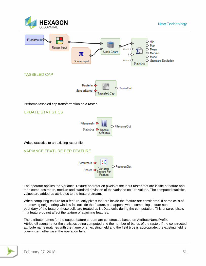
STACK COUNT
Returns a single layer whose pixels contain the number of occurrences of the requested value at that pixel among the layers of RasterIn.
Below is an example of how this operator might be used to determine the number of occurrences in a layer stack of the Stack Majority pixel value.
Below is an example of how this operator might be used to determine the number of occurrences of a particular value in a layer stack.
New Technology
February 27, 2018 51
TASSELED CAP
Performs tasseled cap transformation on a raster.
UPDATE STATISTICS
Writes statistics to an existing raster file.
VARIANCE TEXTURE PER FEATURE
The operator applies the Variance Texture operator on pixels of the input raster that are inside a feature and then computes mean, median and standard deviation of the variance texture values. The computed statistical values are added as attributes to the feature stream.
When computing texture for a feature, only pixels that are inside the feature are considered. If some cells of the moving neighboring window fall outside the feature, as happens when computing texture near the boundary of the feature, these cells are treated as NoData cells during the computation. This ensures pixels in a feature do not affect the texture of adjoining features.
The attribute names for the output feature stream are constructed based on AttributeNamePrefix, AttributeBasename for the statistics being computed and the number of bands of the raster. If the constructed attribute name matches with the name of an existing field and the field type is appropriate, the existing field is overwritten. otherwise, the operation fails.
New Technology
February 27, 2018 52
GENERAL SPATIAL MODELER
ACCEPTABLE VALUES AND OTHER INPUT CONTRAINTS
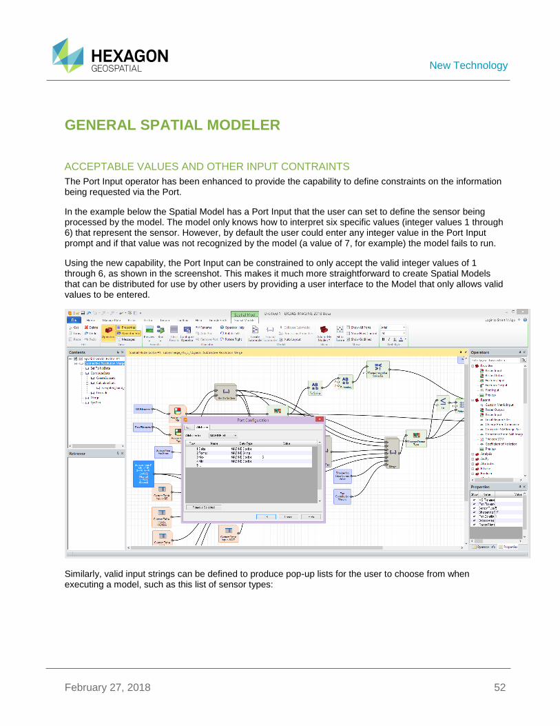
The Port Input operator has been enhanced to provide the capability to define constraints on the information being requested via the Port.
In the example below the Spatial Model has a Port Input that the user can set to define the sensor being processed by the model. The model only knows how to interpret six specific values (integer values 1 through 6) that represent the sensor. However, by default the user could enter any integer value in the Port Input prompt and if that value was not recognized by the model (a value of 7, for example) the model fails to run.
Using the new capability, the Port Input can be constrained to only accept the valid integer values of 1 through 6, as shown in the screenshot. This makes it much more straightforward to create Spatial Models that can be distributed for use by other users by providing a user interface to the Model that only allows valid values to be entered.
Similarly, valid input strings can be defined to produce pop-up lists for the user to choose from when executing a model, such as this list of sensor types:
New Technology
February 27, 2018 53
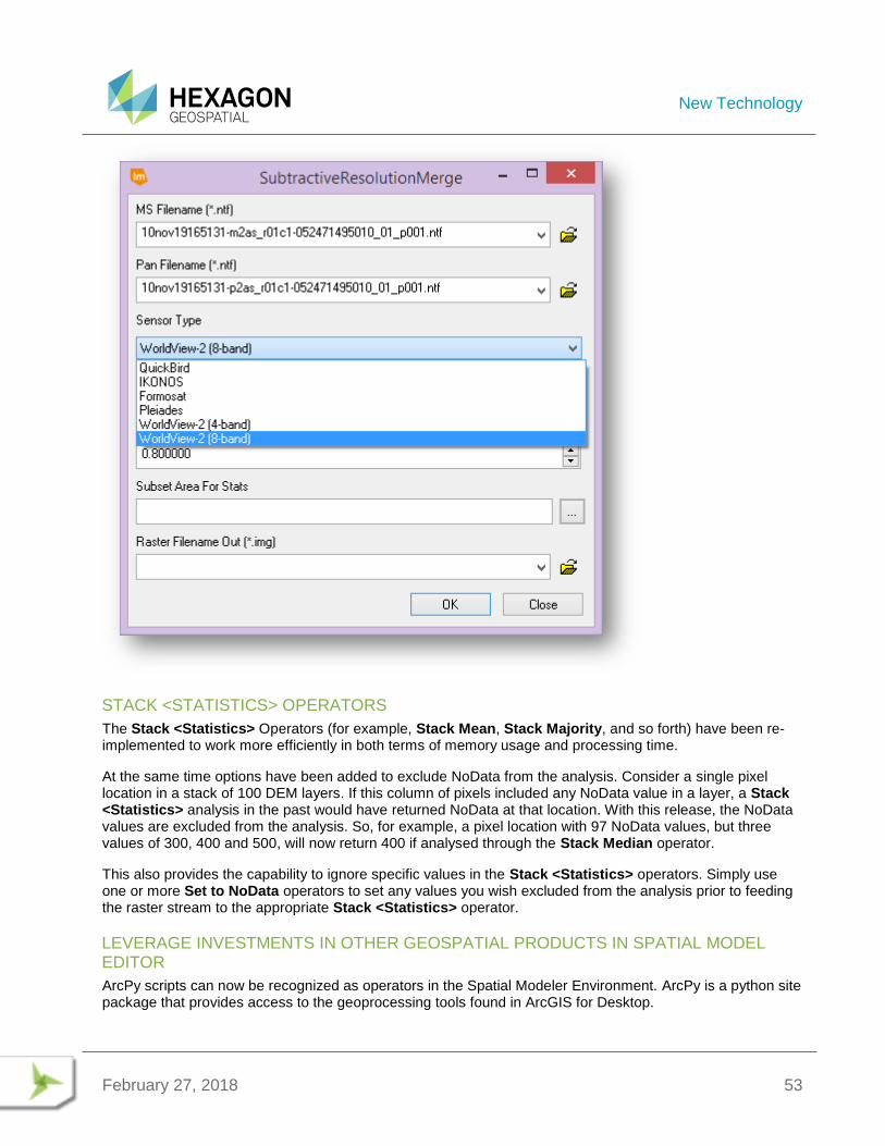
STACK <STATISTICS> OPERATORS
The Stack <Statistics> Operators (for example, Stack Mean, Stack Majority, and so forth) have been re-implemented to work more efficiently in both terms of memory usage and processing time.
At the same time options have been added to exclude NoData from the analysis. Consider a single pixel location in a stack of 100 DEM layers. If this column of pixels included any NoData value in a layer, a Stack <Statistics> analysis in the past would have returned NoData at that location. With this release, the NoData values are excluded from the analysis. So, for example, a pixel location with 97 NoData values, but three values of 300, 400 and 500, will now return 400 if analysed through the Stack Median operator.
This also provides the capability to ignore specific values in the Stack <Statistics> operators. Simply use one or more Set to NoData operators to set any values you wish excluded from the analysis prior to feeding the raster stream to the appropriate Stack <Statistics> operator.
LEVERAGE INVESTMENTS IN OTHER GEOSPATIAL PRODUCTS IN SPATIAL MODEL EDITOR
ArcPy scripts can now be recognized as operators in the Spatial Modeler Environment. ArcPy is a python site package that provides access to the geoprocessing tools found in ArcGIS for Desktop.
New Technology
February 27, 2018 54
Once the scripts are detected by ERDAS IMAGINE, they are listed in the SME operator tree list and can be used in combinations with other operators to leverage the strengths of both ERDAS IMAGINE and GeoMedia in a spatial model.
For details on how to get your ArcPy scripts recognized by ERDAS IMAGINE, see the white paper “Leverage ArcPy scripts in Spatial Modeler” on our website.
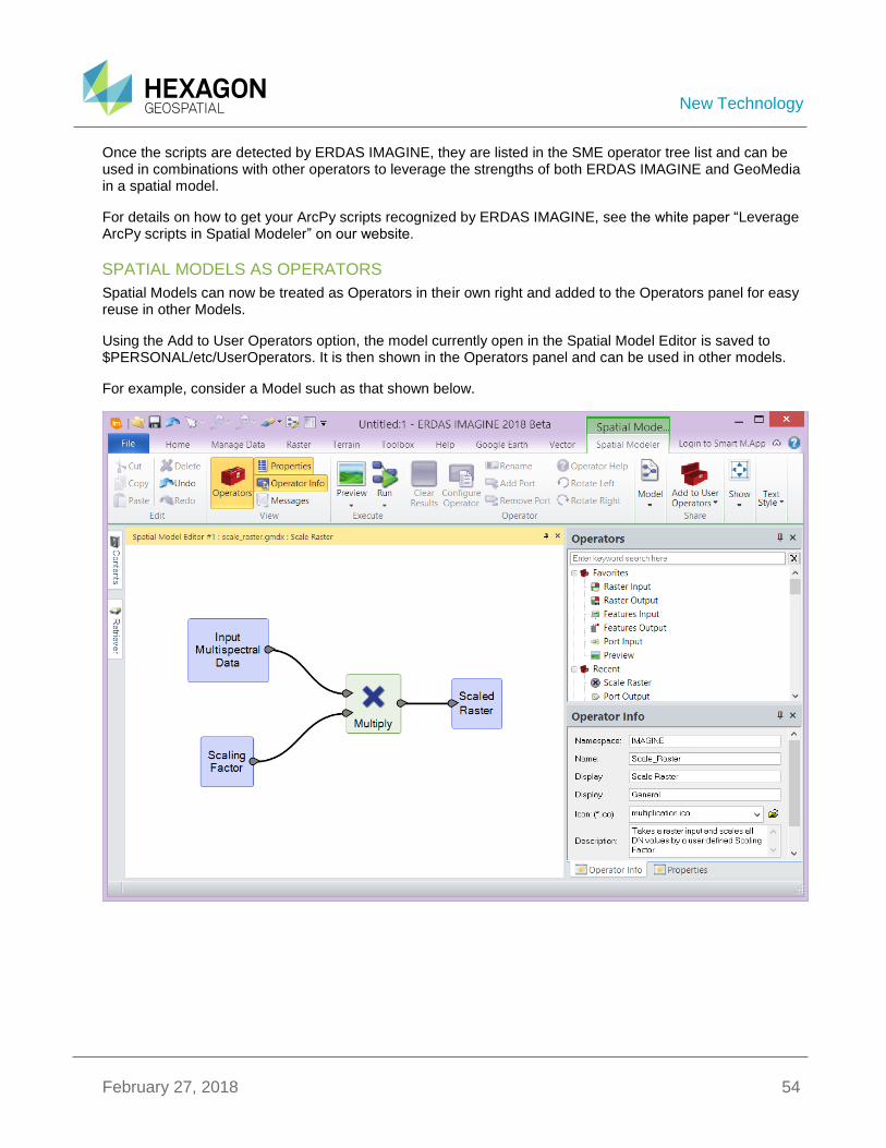
SPATIAL MODELS AS OPERATORS
Spatial Models can now be treated as Operators in their own right and added to the Operators panel for easy reuse in other Models.
Using the Add to User Operators option, the model currently open in the Spatial Model Editor is saved to $PERSONAL/etc/UserOperators. It is then shown in the Operators panel and can be used in other models.
For example, consider a Model such as that shown below.
New Technology
February 27, 2018 55
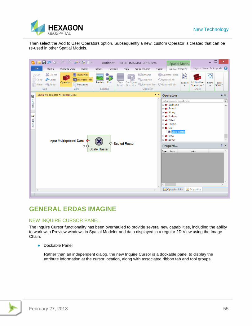
Then select the Add to User Operators option. Subsequently a new, custom Operator is created that can be re-used in other Spatial Models.
GENERAL ERDAS IMAGINE
NEW INQUIRE CURSOR PANEL
The Inquire Cursor functionality has been overhauled to provide several new capabilities, including the ability to work with Preview windows in Spatial Modeler and data displayed in a regular 2D View using the Image Chain.
Dockable Panel
Rather than an independent dialog, the new Inquire Cursor is a dockable panel to display the attribute information at the cursor location, along with associated ribbon tab and tool groups.
New Technology
February 27, 2018 56
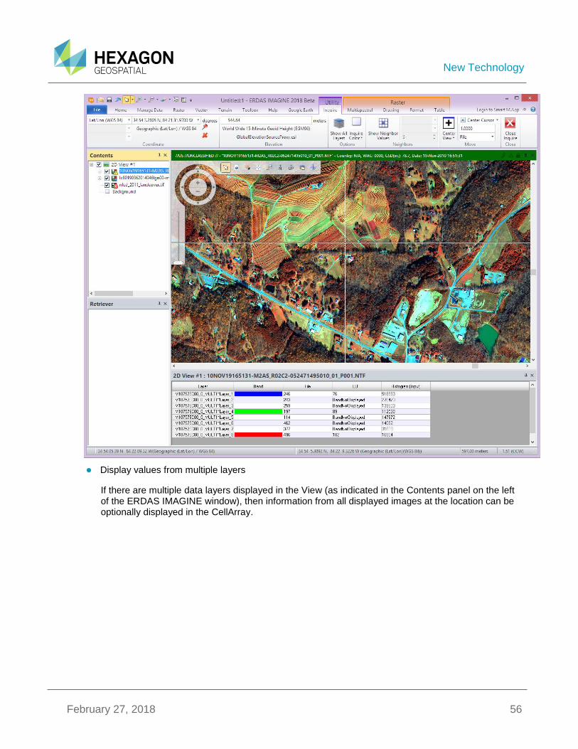
Display values from multiple layers
If there are multiple data layers displayed in the View (as indicated in the Contents panel on the left of the ERDAS IMAGINE window), then information from all displayed images at the location can be optionally displayed in the CellArray.
New Technology
February 27, 2018 57
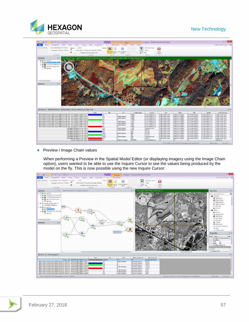
Preview / Image Chain values
When performing a Preview in the Spatial Model Editor (or displaying imagery using the Image Chain option), users wanted to be able to use the Inquire Cursor to see the values being produced by the model on the fly. This is now possible using the new Inquire Cursor:
New Technology
February 27, 2018 58
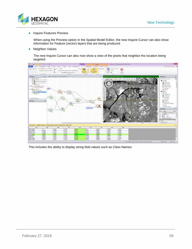
Inquire Features Preview
When using the Preview option in the Spatial Model Editor, the new Inquire Cursor can also show information for Feature (vector) layers that are being produced.
Neighbor Values
The new Inquire Cursor can also now show a view of the pixels that neighbor the location being targeted:
This includes the ability to display string field values such as Class Names:
New Technology
February 27, 2018 59
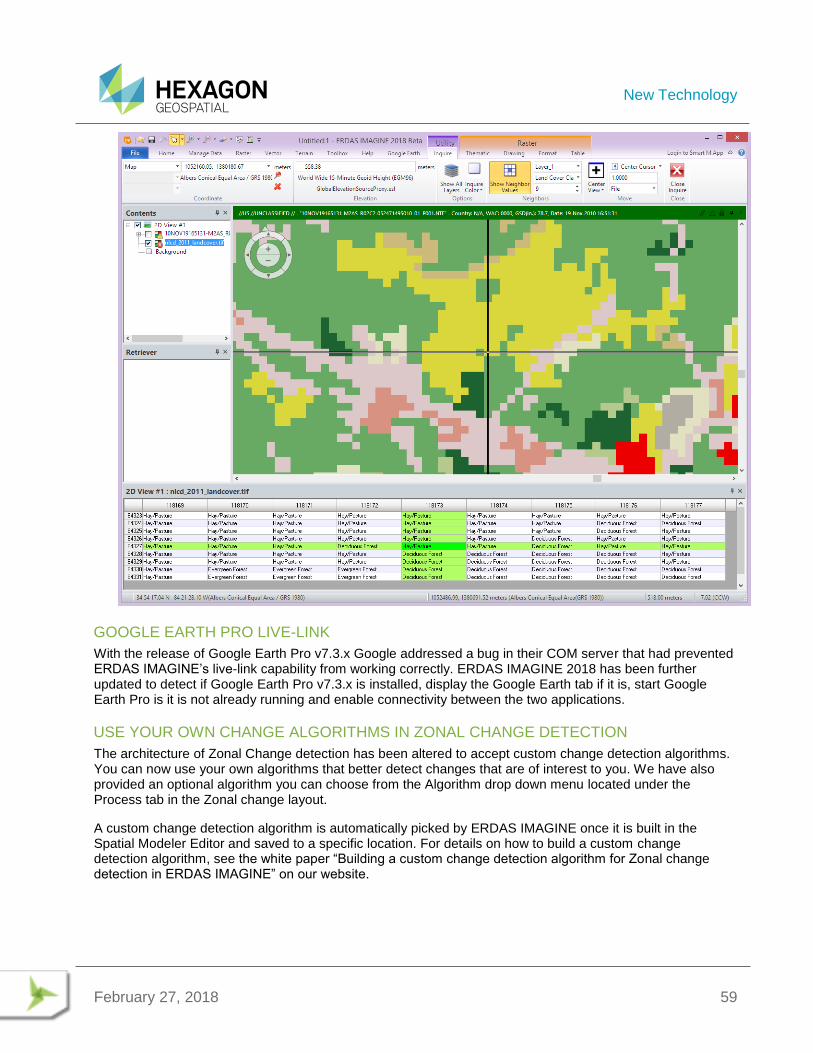
GOOGLE EARTH PRO LIVE-LINK
With the release of Google Earth Pro v7.3.x Google addressed a bug in their COM server that had prevented ERDAS IMAGINE’s live-link capability from working correctly. ERDAS IMAGINE 2018 has been further updated to detect if Google Earth Pro v7.3.x is installed, display the Google Earth tab if it is, start Google Earth Pro is it is not already running and enable connectivity between the two applications.
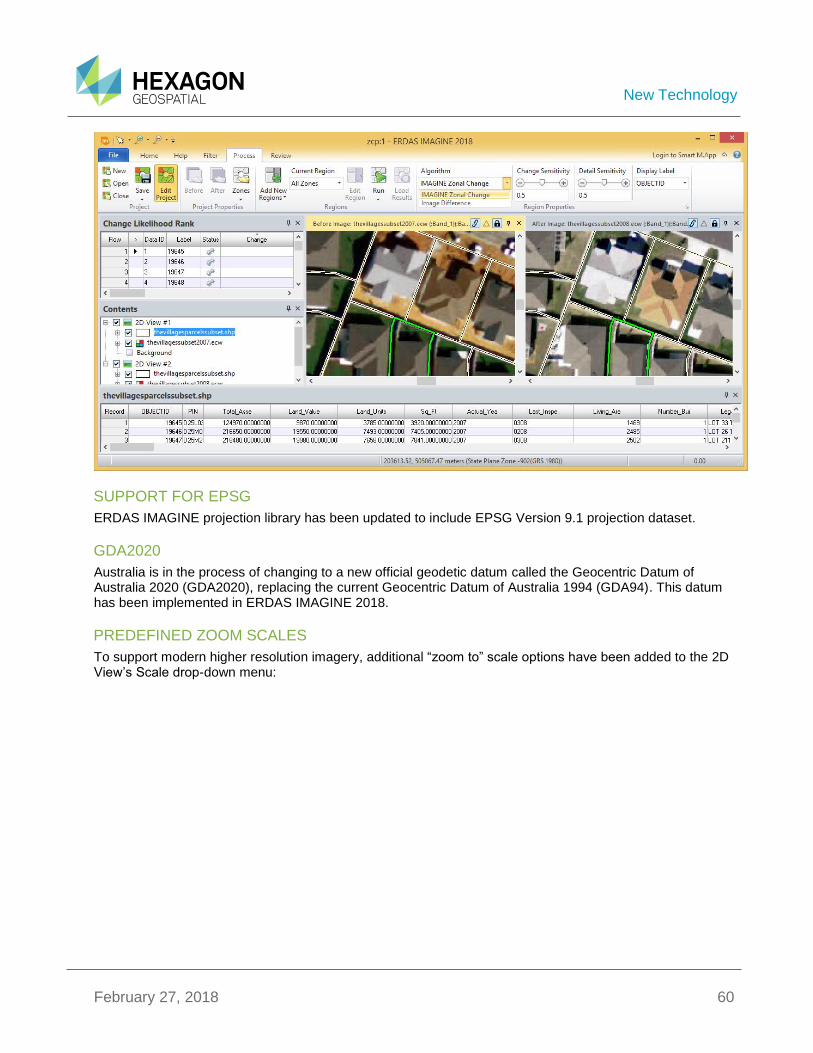
USE YOUR OWN CHANGE ALGORITHMS IN ZONAL CHANGE DETECTION
The architecture of Zonal Change detection has been altered to accept custom change detection algorithms. You can now use your own algorithms that better detect changes that are of interest to you. We have also provided an optional algorithm you can choose from the Algorithm drop down menu located under the Process tab in the Zonal change layout.
A custom change detection algorithm is automatically picked by ERDAS IMAGINE once it is built in the Spatial Modeler Editor and saved to a specific location. For details on how to build a custom change detection algorithm, see the white paper “Building a custom change detection algorithm for Zonal change detection in ERDAS IMAGINE” on our website.
New Technology
February 27, 2018 60
SUPPORT FOR EPSG
ERDAS IMAGINE projection library has been updated to include EPSG Version 9.1 projection dataset.
GDA2020
Australia is in the process of changing to a new official geodetic datum called the Geocentric Datum of Australia 2020 (GDA2020), replacing the current Geocentric Datum of Australia 1994 (GDA94). This datum has been implemented in ERDAS IMAGINE 2018.
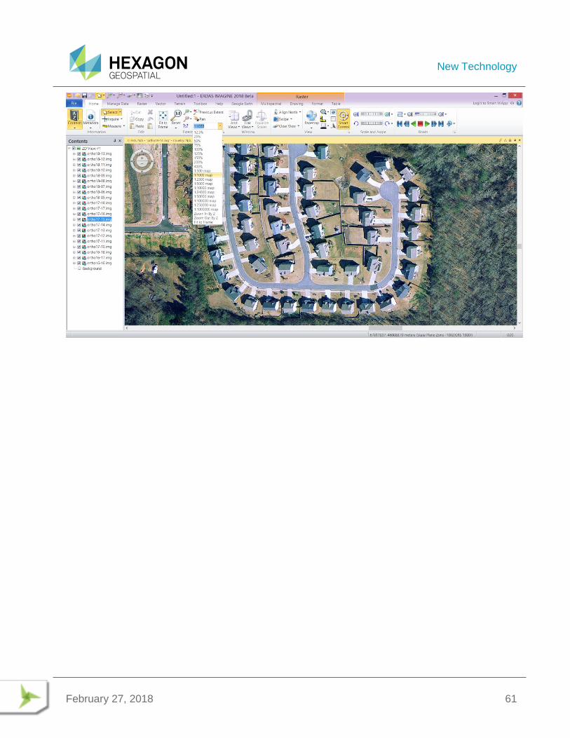
PREDEFINED ZOOM SCALES
To support modern higher resolution imagery, additional “zoom to” scale options have been added to the 2D View’s Scale drop-down menu:
New Technology
February 27, 2018 61
New Technology
February 27, 2018 62
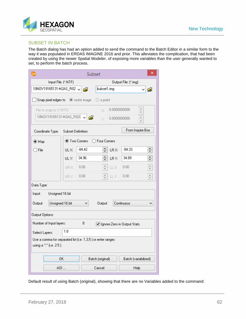
SUBSET IN BATCH
The Batch dialog has had an option added to send the command to the Batch Editor in a similar form to the way it was populated in ERDAS IMAGINE 2016 and prior. This alleviates the complication, that had been created by using the newer Spatial Modeler, of exposing more variables than the user generally wanted to set, to perform the batch process.
Default result of using Batch (original), showing that there are no Variables added to the command:
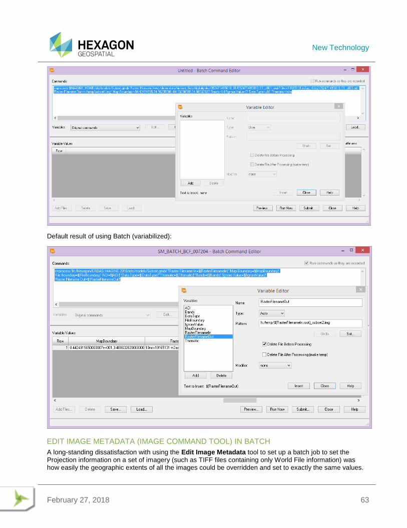
New Technology
February 27, 2018 63
Default result of using Batch (variabilized):
EDIT IMAGE METADATA (IMAGE COMMAND TOOL) IN BATCH
A long-standing dissatisfaction with using the Edit Image Metadata tool to set up a batch job to set the Projection information on a set of imagery (such as TIFF files containing only World File information) was how easily the geographic extents of all the images could be overridden and set to exactly the same values.

New Technology
February 27, 2018 64
This happened when using the Map Info Options dialog to set the preferred Projection, the dialog also passed in the Upper Left X and Upper Left Y map coordinate of the first image. Unless you noticed this (and manually set up variables to replace the fixed values), that single map extent would then be applied by the Batch process to all the input images, along with the preferred Projection.
In ERDAS IMAGINE 2018, Edit Image Metadata has been enhanced so that the Upper Left X, Upper Left Y, Pixel Size X and Pixel Size Y parameters are automatically passed to Batch as variables that pull their information from each input image being processed. Only Projection and Units are passed as fixed values.
However, if you manually set one (or more) of the values in the Map Info Options dialog then those values are assumed to be the preferred values and are passed to the Batch Editor as fixed values as well.
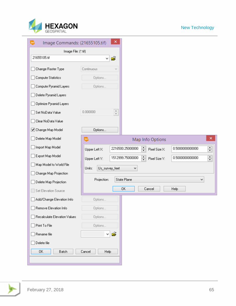
New Technology
February 27, 2018 65
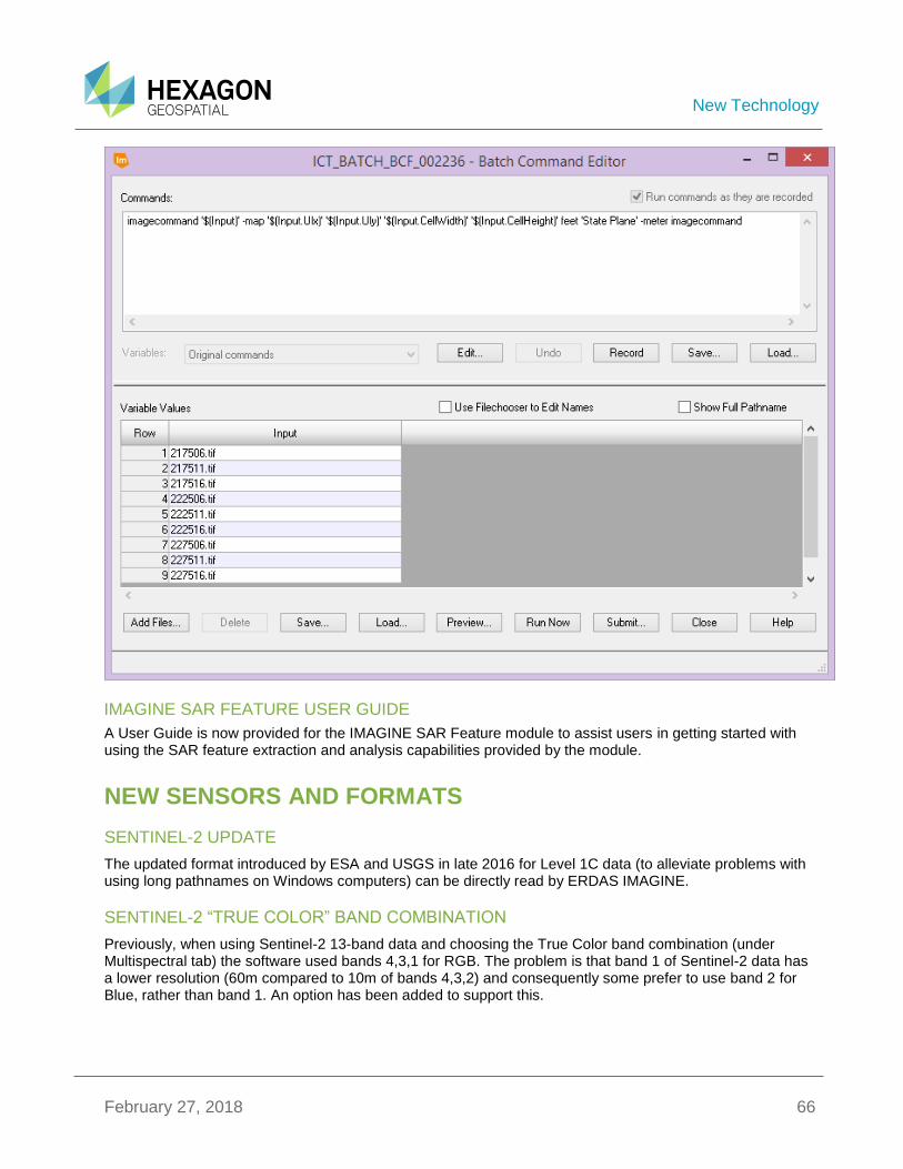
New Technology
February 27, 2018 66
IMAGINE SAR FEATURE USER GUIDE
A User Guide is now provided for the IMAGINE SAR Feature module to assist users in getting started with using the SAR feature extraction and analysis capabilities provided by the module.
NEW SENSORS AND FORMATS
SENTINEL-2 UPDATE
The updated format introduced by ESA and USGS in late 2016 for Level 1C data (to alleviate problems with using long pathnames on Windows computers) can be directly read by ERDAS IMAGINE.
SENTINEL-2 “TRUE COLOR” BAND COMBINATION
Previously, when using Sentinel-2 13-band data and choosing the True Color band combination (under Multispectral tab) the software used bands 4,3,1 for RGB. The problem is that band 1 of Sentinel-2 data has a lower resolution (60m compared to 10m of bands 4,3,2) and consequently some prefer to use band 2 for Blue, rather than band 1. An option has been added to support this.
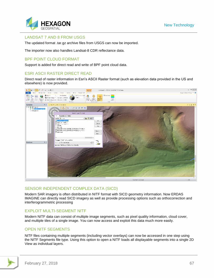
New Technology
February 27, 2018 67
LANDSAT 7 AND 8 FROM USGS
The updated format .tar.gz archive files from USGS can now be imported.
The importer now also handles Landsat-8 CDR reflectance data.
BPF POINT CLOUD FORMAT
Support is added for direct read and write of BPF point cloud data.
ESRI ASCII RASTER DIRECT READ
Direct read of raster information in Esri’s ASCII Raster format (such as elevation data provided in the US and elsewhere) is now provided.
SENSOR INDEPENDENT COMPLEX DATA (SICD)
Modern SAR imagery is often distributed in NITF format with SICD geometry information. Now ERDAS IMAGINE can directly read SICD imagery as well as provide processing options such as orthocorrection and interferogrammetric processing
EXPLOIT MULTI-SEGMENT NITF
Modern NITF data can consist of multiple image segments, such as pixel quality information, cloud cover, and multiple tiles of a single image. You can now access and exploit this data much more easily.
OPEN NITF SEGMENTS
NITF files containing multiple segments (including vector overlays) can now be accessed in one step using the NITF Segments file type. Using this option to open a NITF loads all displayable segments into a single 2D View as individual layers.
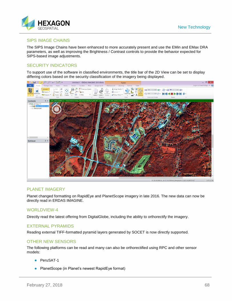
New Technology
February 27, 2018 68
SIPS IMAGE CHAINS
The SIPS Image Chains have been enhanced to more accurately present and use the EMin and EMax DRA parameters, as well as improving the Brightness / Contrast controls to provide the behavior expected for SIPS-based image adjustments.
SECURITY INDICATORS
To support use of the software in classified environments, the title bar of the 2D View can be set to display differing colors based on the security classification of the imagery being displayed.
PLANET IMAGERY
Planet changed formatting on RapidEye and PlanetScope imagery in late 2016. The new data can now be directly read in ERDAS IMAGINE.
WORLDVIEW-4
Directly read the latest offering from DigitalGlobe, including the ability to orthorectify the imagery.
EXTERNAL PYRAMIDS
Reading external TIFF-formatted pyramid layers generated by SOCET is now directly supported.
OTHER NEW SENSORS
The following platforms can be read and many can also be orthorectified using RPC and other sensor models:
PeruSAT-1
PlanetScope (in Planet’s newest RapidEye format)
New Technology
February 27, 2018 69
Sentinel-2 (updated variants)
VNREDSat-1
ERS-1 in ENVISAT format (ASAR) for E2 SLC product
GEOSPATIAL PDF
Creation of multi-layer Geospatial PDF documents from input imagery and overlay layers, or single layer documents from map compositions is now provided using GDAL’s Geospatial PDF engine.
Geospatial PDF documents can also be generated in the Spatial Modeler Environment using the Create Geospatial PDF operator.
IMAGINE SAR INTERFEROMETRY
SENTINEL-1 SWATH TIME-SERIES COHERENCE CHANGE DETECTION (CCD)
This tool streamlines the process of setting up and performing a multi-image time series analysis of Sentinel-1 Swath imagery.
MULTI-POLAR CCD ANALYSIS
Multi-polar SAR imagery can now be used in the Coherence Change Detection tools.
IMPROVED INTERFEROMETRIC COREGISTRATION
Image co-registration is basic to all interferometric processing and fundamental in determining final accuracy. The co-registration algorithm has been updated to deal with modern sensors such as Sentinel-1 and PalSAR
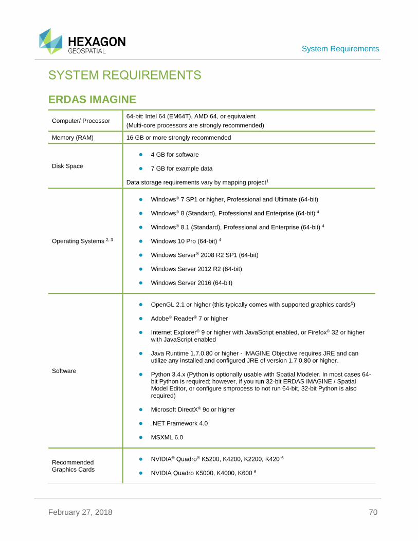
System Requirements
February 27, 2018 70
SYSTEM REQUIREMENTS
ERDAS IMAGINE
Computer/ Processor 64-bit: Intel 64 (EM64T), AMD 64, or equivalent
(Multi-core processors are strongly recommended)
Memory (RAM) 16 GB or more strongly recommended
Disk Space
4 GB for software
7 GB for example data
Data storage requirements vary by mapping project1
Operating Systems 2, 3
Windows® 7 SP1 or higher, Professional and Ultimate (64-bit)
Windows® 8 (Standard), Professional and Enterprise (64-bit) 4
Windows® 8.1 (Standard), Professional and Enterprise (64-bit) 4
Windows 10 Pro (64-bit) 4
Windows Server® 2008 R2 SP1 (64-bit)
Windows Server 2012 R2 (64-bit)
Windows Server 2016 (64-bit)
Software
OpenGL 2.1 or higher (this typically comes with supported graphics cards5)
Adobe® Reader® 7 or higher
Internet Explorer® 9 or higher with JavaScript enabled, or Firefox® 32 or higher with JavaScript enabled
Java Runtime 1.7.0.80 or higher - IMAGINE Objective requires JRE and can utilize any installed and configured JRE of version 1.7.0.80 or higher.
Python 3.4.x (Python is optionally usable with Spatial Modeler. In most cases 64-bit Python is required; however, if you run 32-bit ERDAS IMAGINE / Spatial Model Editor, or configure smprocess to not run 64-bit, 32-bit Python is also required)
Microsoft DirectX® 9c or higher
.NET Framework 4.0
MSXML 6.0
Recommended Graphics Cards
NVIDIA® Quadro® K5200, K4200, K2200, K420 6
NVIDIA Quadro K5000, K4000, K600 6

System Requirements
February 27, 2018 71
Recommended Stereo Display Monitors
120 Hz (or above) LCD Monitors with NVIDIA 3D Vision™ Kit 7
Peripherals
All software installations require:
One Windows-compatible mouse with scroll wheel or equivalent input device
Printing requires Windows-supported hardcopy devices 8
Software security (Hexagon Geospatial Licensing 2018) requires one of the following:
Ethernet card, or
One USB port for hardware key
Advanced data collection requires one of the following hand controllers: 9
TopoMouse™ or TopoMouse USB™
Immersion 3D Mouse
MOUSE-TRAK
Stealth 3D (Immersion), S3D-E type, Serial Port
Stealth Z, S2-Z model, USB version
Stealth V, S3-V type (add as a serial device)
3Dconnexion SpaceExplorer mouse 10
EK2000 Hand Wheels
EMSEN Hand Wheels
Z/I Mouse
ArcGIS and GeoMedia Interoperability
ERDAS IMAGINE can be safely installed on a computer that has GeoMedia 2014, GeoMedia 2015, GeoMedia 2016 or GeoMedia 2018 installed. However for greatest compatibility, it is highly recommended to install matching versions.
ERDAS IMAGINE 2018 requires GeoMedia 2018 for live linking. Order of installation does not matter.
ERDAS IMAGINE can interact with both types of personal Geodatabases (*.mdb and *.gdb).
ERDAS IMAGINE can be safely installed on a computer that has ArcGIS® versions 10 through 10.5.1.
ERDAS IMAGINE and IMAGINE Photogrammetry can interact with ArcGIS Server 10 Geodatabase servers (ArcSDE). To read or interact with an Enterprise Geodatabase, you must either:
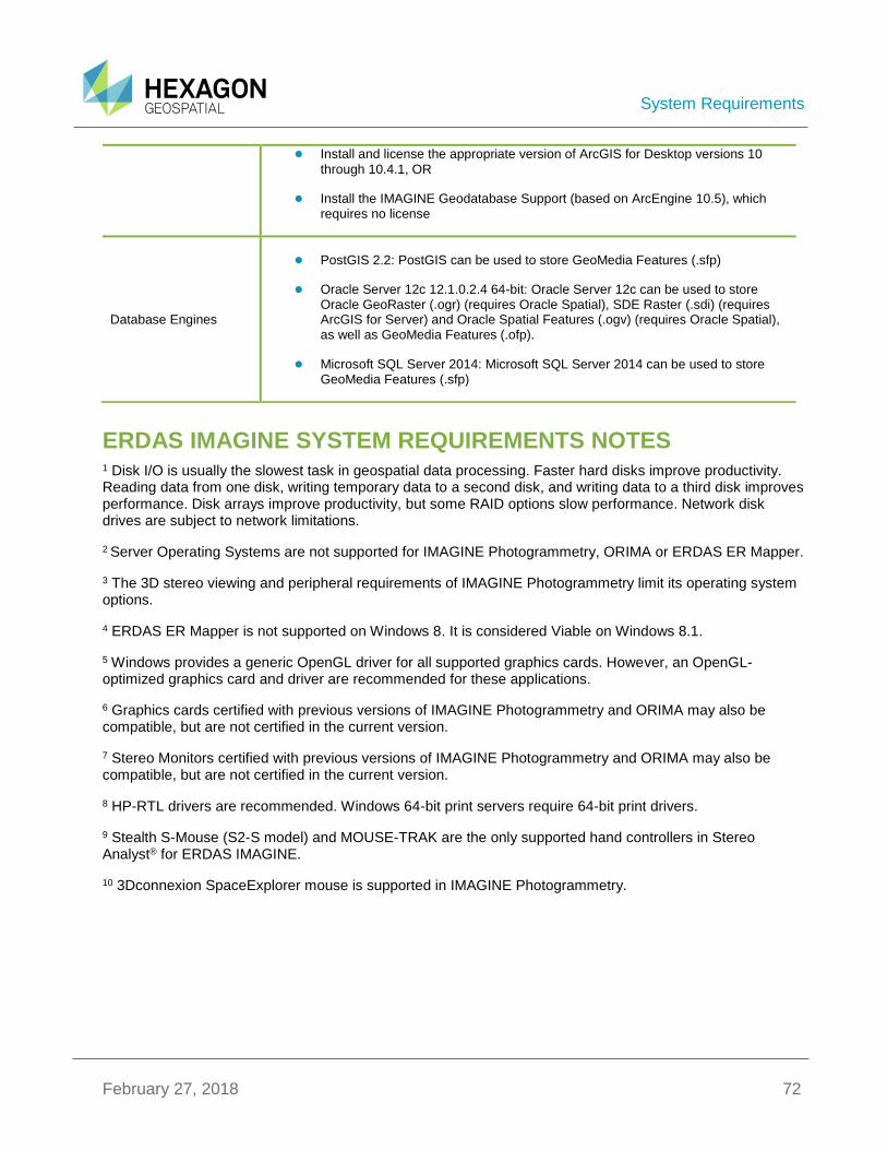
System Requirements
February 27, 2018 72
Install and license the appropriate version of ArcGIS for Desktop versions 10
through 10.4.1, OR
Install the IMAGINE Geodatabase Support (based on ArcEngine 10.5), which requires no license
Database Engines
PostGIS 2.2: PostGIS can be used to store GeoMedia Features (.sfp)
Oracle Server 12c 12.1.0.2.4 64-bit: Oracle Server 12c can be used to store Oracle GeoRaster (.ogr) (requires Oracle Spatial), SDE Raster (.sdi) (requires ArcGIS for Server) and Oracle Spatial Features (.ogv) (requires Oracle Spatial), as well as GeoMedia Features (.ofp).
Microsoft SQL Server 2014: Microsoft SQL Server 2014 can be used to store GeoMedia Features (.sfp)
ERDAS IMAGINE SYSTEM REQUIREMENTS NOTES 1 Disk I/O is usually the slowest task in geospatial data processing. Faster hard disks improve productivity. Reading data from one disk, writing temporary data to a second disk, and writing data to a third disk improves performance. Disk arrays improve productivity, but some RAID options slow performance. Network disk drives are subject to network limitations.
2 Server Operating Systems are not supported for IMAGINE Photogrammetry, ORIMA or ERDAS ER Mapper.
3 The 3D stereo viewing and peripheral requirements of IMAGINE Photogrammetry limit its operating system options.
4 ERDAS ER Mapper is not supported on Windows 8. It is considered Viable on Windows 8.1.
5 Windows provides a generic OpenGL driver for all supported graphics cards. However, an OpenGL-optimized graphics card and driver are recommended for these applications.
6 Graphics cards certified with previous versions of IMAGINE Photogrammetry and ORIMA may also be compatible, but are not certified in the current version.
7 Stereo Monitors certified with previous versions of IMAGINE Photogrammetry and ORIMA may also be compatible, but are not certified in the current version.
8 HP-RTL drivers are recommended. Windows 64-bit print servers require 64-bit print drivers.
9 Stealth S-Mouse (S2-S model) and MOUSE-TRAK are the only supported hand controllers in Stereo Analyst® for ERDAS IMAGINE.
10 3Dconnexion SpaceExplorer mouse is supported in IMAGINE Photogrammetry.
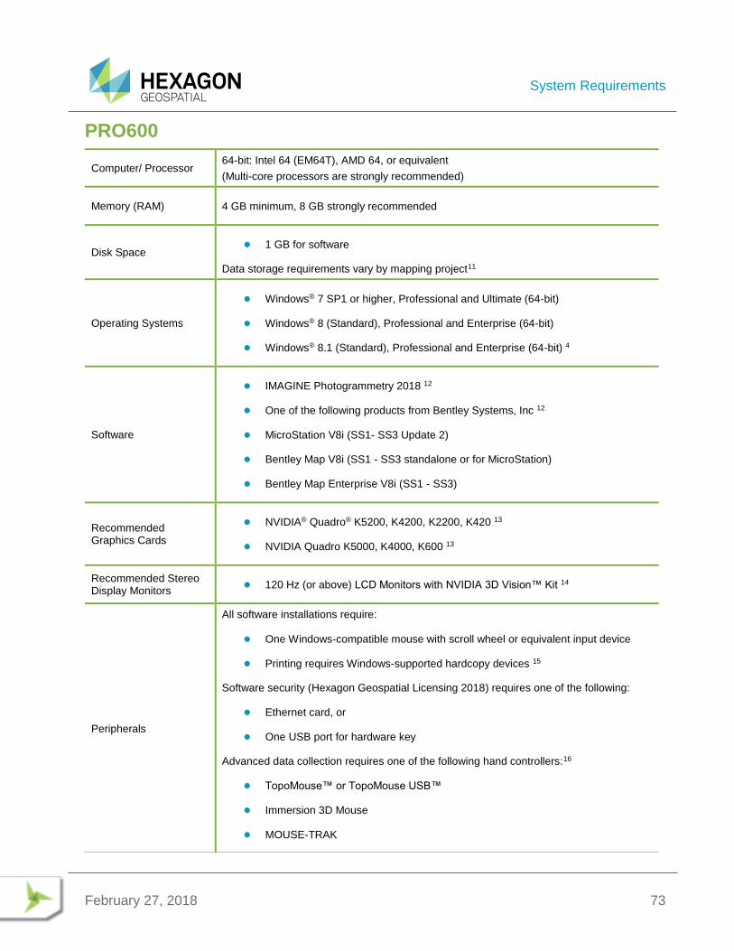
System Requirements
February 27, 2018 73
PRO600
Computer/ Processor 64-bit: Intel 64 (EM64T), AMD 64, or equivalent
(Multi-core processors are strongly recommended)
Memory (RAM) 4 GB minimum, 8 GB strongly recommended
Disk Space 1 GB for software
Data storage requirements vary by mapping project11
Operating Systems
Windows® 7 SP1 or higher, Professional and Ultimate (64-bit)
Windows® 8 (Standard), Professional and Enterprise (64-bit)
Windows® 8.1 (Standard), Professional and Enterprise (64-bit) 4
Software
IMAGINE Photogrammetry 2018 12
One of the following products from Bentley Systems, Inc 12
MicroStation V8i (SS1- SS3 Update 2)
Bentley Map V8i (SS1 - SS3 standalone or for MicroStation)
Bentley Map Enterprise V8i (SS1 - SS3)
Recommended Graphics Cards
NVIDIA® Quadro® K5200, K4200, K2200, K420 13
NVIDIA Quadro K5000, K4000, K600 13
Recommended Stereo Display Monitors
120 Hz (or above) LCD Monitors with NVIDIA 3D Vision™ Kit 14
Peripherals
All software installations require:
One Windows-compatible mouse with scroll wheel or equivalent input device
Printing requires Windows-supported hardcopy devices 15
Software security (Hexagon Geospatial Licensing 2018) requires one of the following:
Ethernet card, or
One USB port for hardware key
Advanced data collection requires one of the following hand controllers:16
TopoMouse™ or TopoMouse USB™
Immersion 3D Mouse
MOUSE-TRAK

System Requirements
February 27, 2018 74
Stealth 3D (Immersion), S3D-E type, Serial Port
Stealth Z, S2-Z model, USB version
Stealth V, S3-V type (add as a serial device)
3Dconnexion SpaceExplorer mouse
EK2000 Hand Wheels
EMSEN Hand Wheels
Z/I Mouse
PRO600 SYSTEM REQUIREMENTS NOTES 11 Disk I/O is usually the slowest task in geospatial data processing. Faster hard disks improve productivity. Reading data from one disk, writing temporary data to a second disk, and writing data to a third disk improves performance. Disk arrays improve productivity, but some RAID options slow performance. Network disk drives are subject to network limitations.
12 Any further requirements defined by any of the listed apply implicitly to PRO600.
13 Graphics cards certified with previous versions of PRO600 may also be compatible, but are not certified in the current version.
14 Stereo Monitors certified with previous versions of PRO600 may also be compatible, but are not certified in the current version.
15 HP-RTL drivers are recommended. Windows 64-bit print servers require 64-bit print drivers.
16 Stealth S-Mouse (S2-S model) and MOUSE-TRAK are only supported in Stereo Analyst® for ERDAS IMAGINE.
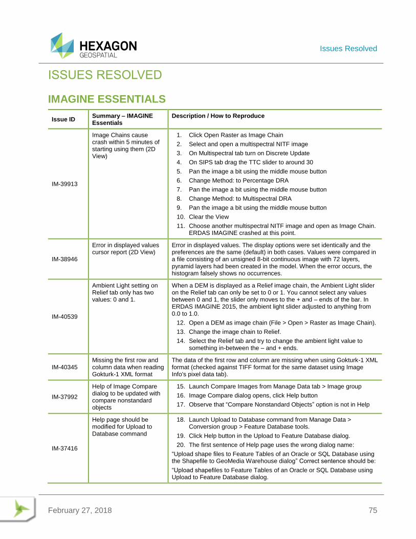
Issues Resolved
February 27, 2018 75
ISSUES RESOLVED
IMAGINE ESSENTIALS
Issue ID Summary – IMAGINE Essentials
Description / How to Reproduce
IM-39913
Image Chains cause crash within 5 minutes of starting using them (2D View)
1. Click Open Raster as Image Chain
2. Select and open a multispectral NITF image
3. On Multispectral tab turn on Discrete Update
4. On SIPS tab drag the TTC slider to around 30
5. Pan the image a bit using the middle mouse button
6. Change Method: to Percentage DRA
7. Pan the image a bit using the middle mouse button
8. Change Method: to Multispectral DRA
9. Pan the image a bit using the middle mouse button
10. Clear the View
11. Choose another multispectral NITF image and open as Image Chain. ERDAS IMAGINE crashed at this point.
IM-38946
Error in displayed values cursor report (2D View)
Error in displayed values. The display options were set identically and the preferences are the same (default) in both cases. Values were compared in a file consisting of an unsigned 8-bit continuous image with 72 layers, pyramid layers had been created in the model. When the error occurs, the histogram falsely shows no occurrences.
IM-40539
Ambient Light setting on Relief tab only has two values: 0 and 1.
When a DEM is displayed as a Relief image chain, the Ambient Light slider on the Relief tab can only be set to 0 or 1. You cannot select any values between 0 and 1, the slider only moves to the + and – ends of the bar. In ERDAS IMAGINE 2015, the ambient light slider adjusted to anything from 0.0 to 1.0.
12. Open a DEM as image chain (File > Open > Raster as Image Chain).
13. Change the image chain to Relief.
14. Select the Relief tab and try to change the ambient light value to something in-between the – and + ends.
IM-40345 Missing the first row and column data when reading Gokturk-1 XML format
The data of the first row and column are missing when using Gokturk-1 XML format (checked against TIFF format for the same dataset using Image Info's pixel data tab).
IM-37992
Help of Image Compare dialog to be updated with compare nonstandard objects
15. Launch Compare Images from Manage Data tab > Image group
16. Image Compare dialog opens, click Help button
17. Observe that “Compare Nonstandard Objects” option is not in Help
IM-37416
Help page should be modified for Upload to Database command
18. Launch Upload to Database command from Manage Data > Conversion group > Feature Database tools.
19. Click Help button in the Upload to Feature Database dialog.
20. The first sentence of Help page uses the wrong dialog name:
“Upload shape files to Feature Tables of an Oracle or SQL Database using the Shapefile to GeoMedia Warehouse dialog” Correct sentence should be:
“Upload shapefiles to Feature Tables of an Oracle or SQL Database using Upload to Feature Database dialog.

Issues Resolved
February 27, 2018 76
IM-41124
Retriever panel OLH should be updated because GeoServices option has been removed
GeoServices option has been removed from the Retriever panel. The OLH should also be updated.
IM-40184
Cannot define elevation information for Virtual Mosaics any longer
Add/Change Elevation Info for Virtual Mosaics (.vmc/.vmcx) is not available in v16.1. A customer who recently migrated from ERDAS IMAGINE 2011 to 2016 reported this. Their workflow was to create a virtual mosaic of a lot of dense elevation files (TIFF format). Once the mosaic was defined, they used ImageInfo to define the vertical datum.
IM-40097
MGRS Grid Zone Element Tool does nothing
1. Open an image in a Map View.
2. From the Layout tab click Map Grid drop-down menu and choose MGRS Grid Zone Element.
With the other grid tools there is a crosshair when pausing on the image, but this tool does nothing.
IM-35756 Chipping: Incorrect HISTOA display flag in Chips
Chips have incorrect Display Flag of blank for some specific SAR data. Since no image enhancements have been applied, the display flag of 0 should be carried forward from the previous event.
IM-41014
ERDAS IMAGINE reprojects NZTM to EPSG 4326 incorrectly
1. Open WGS84_Coords.shp.
2. Run Vector > Reproject Shapefile to create two derived shapefiles
- Target projection: named ‘NZTM’ in standard list of projections
- Target projection: EPSG 2193
3. Overlay the output shapefiles with the original WGS84 in GeoMedia
- The file named ‘EPSG’ 2193 aligns correctly.
- The file named ‘NZTM’ not.
IM-38975
NAD83 (2011) projection recognition
Lidar data in NAD83 (2011) projection is recognized in ERDAS IMAGINE 2015 as GRS 1980 NAD83 (26918).
ERDAS IMAGINE should be able to resolve the NAD83 (2011) datum usage by identifying the datum references that are found in the ProjectionX tab of an IMG file produced by a third-party GIS package.
IM-41064
Enable Editing mode cannot be deactivated when shapefile is displayed in two different 2D Views
When a shapefile is displayed in two separate 2D Views, click Enable Editing button in the Drawing tab to make edits to the vector layer. Now, attempt to deactivate the editing mode by clicking the Enable Editing button again. When you click the Enable Editing button to stop making edits to the vector layer, the Verify Save on Close dialog opens asking if you want to save the changes before closing. When you click Yes it saves the vector file, but it is still in editing mode. When you click No it remains in editing mode. Sometimes ERDAS IMAGINE crashes when you click Yes to save the vector file, click the Enable Editing button again (trying to turn it off) and click Yes to save the changes again.
4. Open two 2D Views.
5. Display the shapefile germtm_poly.shp in both 2D Views.
6. Enable editing mode by clicking Drawing tab > Modify group > Enable Editing button.
7. Select the polygon and move it to a new position.
8. Try to disable editing mode by clicking the Enable Editing button again.
9. The Verify Save on Close dialog asks if you want to save the changes before closing.
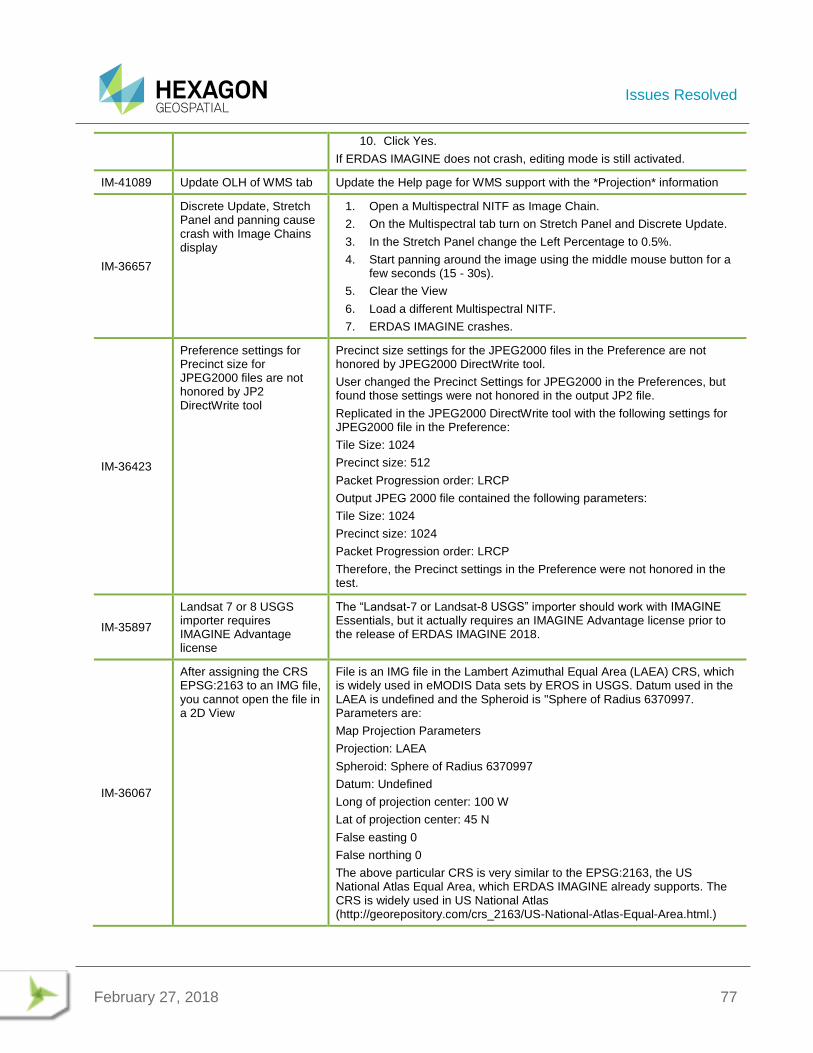
Issues Resolved
February 27, 2018 77
10. Click Yes.
If ERDAS IMAGINE does not crash, editing mode is still activated.
IM-41089 Update OLH of WMS tab Update the Help page for WMS support with the *Projection* information
IM-36657
Discrete Update, Stretch Panel and panning cause crash with Image Chains display
1. Open a Multispectral NITF as Image Chain.
2. On the Multispectral tab turn on Stretch Panel and Discrete Update.
3. In the Stretch Panel change the Left Percentage to 0.5%.
4. Start panning around the image using the middle mouse button for a few seconds (15 - 30s).
5. Clear the View
6. Load a different Multispectral NITF.
7. ERDAS IMAGINE crashes.
IM-36423
Preference settings for Precinct size for JPEG2000 files are not honored by JP2 DirectWrite tool
Precinct size settings for the JPEG2000 files in the Preference are not honored by JPEG2000 DirectWrite tool.
User changed the Precinct Settings for JPEG2000 in the Preferences, but found those settings were not honored in the output JP2 file.
Replicated in the JPEG2000 DirectWrite tool with the following settings for JPEG2000 file in the Preference:
Tile Size: 1024
Precinct size: 512
Packet Progression order: LRCP
Output JPEG 2000 file contained the following parameters:
Tile Size: 1024
Precinct size: 1024
Packet Progression order: LRCP
Therefore, the Precinct settings in the Preference were not honored in the test.
IM-35897
Landsat 7 or 8 USGS importer requires IMAGINE Advantage license
The “Landsat-7 or Landsat-8 USGS” importer should work with IMAGINE Essentials, but it actually requires an IMAGINE Advantage license prior to the release of ERDAS IMAGINE 2018.
IM-36067
After assigning the CRS EPSG:2163 to an IMG file, you cannot open the file in a 2D View
File is an IMG file in the Lambert Azimuthal Equal Area (LAEA) CRS, which is widely used in eMODIS Data sets by EROS in USGS. Datum used in the LAEA is undefined and the Spheroid is "Sphere of Radius 6370997. Parameters are:
Map Projection Parameters
Projection: LAEA
Spheroid: Sphere of Radius 6370997
Datum: Undefined
Long of projection center: 100 W
Lat of projection center: 45 N
False easting 0
False northing 0
The above particular CRS is very similar to the EPSG:2163, the US National Atlas Equal Area, which ERDAS IMAGINE already supports. The CRS is widely used in US National Atlas (http://georepository.com/crs_2163/US-National-Atlas-Equal-Area.html.)
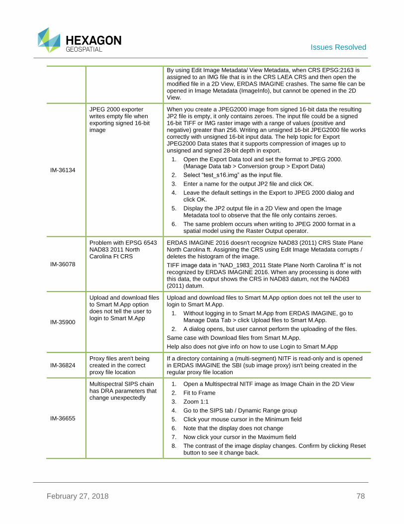
Issues Resolved
February 27, 2018 78
By using Edit Image Metadata/ View Metadata, when CRS EPSG:2163 is assigned to an IMG file that is in the CRS LAEA CRS and then open the modified file in a 2D View, ERDAS IMAGINE crashes. The same file can be opened in Image Metadata (ImageInfo), but cannot be opened in the 2D View.
IM-36134
JPEG 2000 exporter writes empty file when exporting signed 16-bit image
When you create a JPEG2000 image from signed 16-bit data the resulting JP2 file is empty, it only contains zeroes. The input file could be a signed 16-bit TIFF or IMG raster image with a range of values (positive and negative) greater than 256. Writing an unsigned 16-bit JPEG2000 file works correctly with unsigned 16-bit input data. The help topic for Export JPEG2000 Data states that it supports compression of images up to unsigned and signed 28-bit depth in export.
1. Open the Export Data tool and set the format to JPEG 2000. (Manage Data tab > Conversion group > Export Data)
2. Select “test_s16.img” as the input file.
3. Enter a name for the output JP2 file and click OK.
4. Leave the default settings in the Export to JPEG 2000 dialog and click OK.
5. Display the JP2 output file in a 2D View and open the Image Metadata tool to observe that the file only contains zeroes.
6. The same problem occurs when writing to JPEG 2000 format in a spatial model using the Raster Output operator.
IM-36078
Problem with EPSG 6543 NAD83 2011 North Carolina Ft CRS
ERDAS IMAGINE 2016 doesn't recognize NAD83 (2011) CRS State Plane North Carolina ft. Assigning the CRS using Edit Image Metadata corrupts / deletes the histogram of the image.
TIFF image data in “NAD_1983_2011 State Plane North Carolina ft” is not recognized by ERDAS IMAGINE 2016. When any processing is done with this data, the output shows the CRS in NAD83 datum, not the NAD83 (2011) datum.
IM-35900
Upload and download files to Smart M.App option does not tell the user to login to Smart M.App
Upload and download files to Smart M.App option does not tell the user to login to Smart M.App.
1. Without logging in to Smart M.App from ERDAS IMAGINE, go to Manage Data Tab > click Upload files to Smart M.App.
2. A dialog opens, but user cannot perform the uploading of the files.
Same case with Download files from Smart M.App.
Help also does not give info on how to use Login to Smart M.App
IM-36824 Proxy files aren't being created in the correct proxy file location
If a directory containing a (multi-segment) NITF is read-only and is opened in ERDAS IMAGINE the SBI (sub image proxy) isn't being created in the regular proxy file location
IM-36655
Multispectral SIPS chain has DRA parameters that change unexpectedly
1. Open a Multispectral NITF image as Image Chain in the 2D View
2. Fit to Frame
3. Zoom 1:1
4. Go to the SIPS tab / Dynamic Range group
5. Click your mouse cursor in the Minimum field
6. Note that the display does not change
7. Now click your cursor in the Maximum field
8. The contrast of the image display changes. Confirm by clicking Reset button to see it change back.
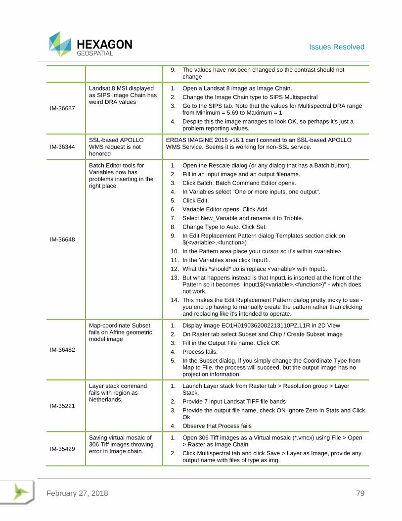
Issues Resolved
February 27, 2018 79
9. The values have not been changed so the contrast should not change
IM-36687
Landsat 8 MSI displayed as SIPS Image Chain has weird DRA values
1. Open a Landsat 8 image as Image Chain.
2. Change the Image Chain type to SIPS Multispectral
3. Go to the SIPS tab. Note that the values for Multispectral DRA range from Minimum = 5.69 to Maximum = 1
4. Despite this the image manages to look OK, so perhaps it's just a problem reporting values.
IM-36344 SSL-based APOLLO WMS request is not honored
ERDAS IMAGINE 2016 v16.1 can’t connect to an SSL-based APOLLO WMS Service. Seems it is working for non-SSL service.
IM-36648
Batch Editor tools for Variables now has problems inserting in the right place
1. Open the Rescale dialog (or any dialog that has a Batch button).
2. Fill in an input image and an output filename.
3. Click Batch. Batch Command Editor opens.
4. In Variables select "One or more inputs, one output".
5. Click Edit.
6. Variable Editor opens. Click Add.
7. Select New_Variable and rename it to Tribble.
8. Change Type to Auto. Click Set.
9. In Edit Replacement Pattern dialog Templates section click on $(<variable>.<function>)
10. In the Pattern area place your cursor so it's within <variable>
11. In the Variables area click Input1.
12. What this *should* do is replace <variable> with Input1.
13. But what happens instead is that Input1 is inserted at the front of the Pattern so it becomes "Input1$(<variable>.<function>)" - which does not work.
14. This makes the Edit Replacement Pattern dialog pretty tricky to use - you end up having to manually create the pattern rather than clicking and replacing like it's intended to operate.
IM-36482
Map-coordinate Subset fails on Affine geometric model image
1. Display image EO1H0190362002213110PZ.L1R in 2D View
2. On Raster tab select Subset and Chip / Create Subset Image
3. Fill in the Output File name. Click OK
4. Process fails.
5. In the Subset dialog, if you simply change the Coordinate Type from Map to File, the process will succeed, but the output image has no projection information.
IM-35221
Layer stack command fails with region as Netherlands.
1. Launch Layer stack from Raster tab > Resolution group > Layer Stack.
2. Provide 7 input Landsat TIFF file bands
3. Provide the output file name, check ON Ignore Zero in Stats and Click Ok
4. Observe that Process fails
IM-35429
Saving virtual mosaic of 306 Tiff images throwing error in Image chain.
1. Open 306 Tiff images as a Virtual mosaic (*.vmcx) using File > Open > Raster as Image Chain
2. Click Multispectral tab and click Save > Layer as Image, provide any output name with files of type as img.
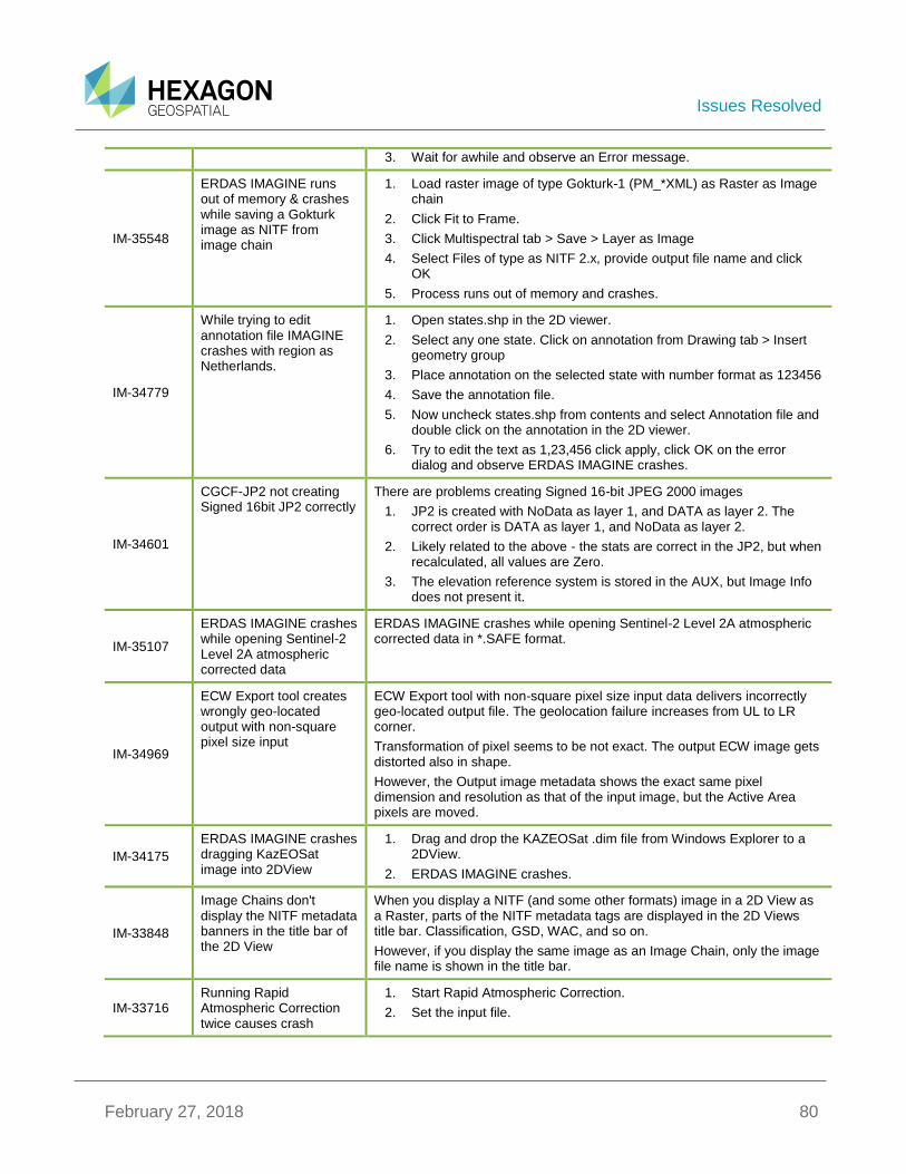
Issues Resolved
February 27, 2018 80
3. Wait for awhile and observe an Error message.
IM-35548
ERDAS IMAGINE runs out of memory & crashes while saving a Gokturk image as NITF from image chain
1. Load raster image of type Gokturk-1 (PM_*XML) as Raster as Image chain
2. Click Fit to Frame.
3. Click Multispectral tab > Save > Layer as Image
4. Select Files of type as NITF 2.x, provide output file name and click OK
5. Process runs out of memory and crashes.
IM-34779
While trying to edit annotation file IMAGINE crashes with region as Netherlands.
1. Open states.shp in the 2D viewer.
2. Select any one state. Click on annotation from Drawing tab > Insert geometry group
3. Place annotation on the selected state with number format as 123456
4. Save the annotation file.
5. Now uncheck states.shp from contents and select Annotation file and double click on the annotation in the 2D viewer.
6. Try to edit the text as 1,23,456 click apply, click OK on the error dialog and observe ERDAS IMAGINE crashes.
IM-34601
CGCF-JP2 not creating Signed 16bit JP2 correctly
There are problems creating Signed 16-bit JPEG 2000 images
1. JP2 is created with NoData as layer 1, and DATA as layer 2. The correct order is DATA as layer 1, and NoData as layer 2.
2. Likely related to the above - the stats are correct in the JP2, but when recalculated, all values are Zero.
3. The elevation reference system is stored in the AUX, but Image Info does not present it.
IM-35107
ERDAS IMAGINE crashes while opening Sentinel-2 Level 2A atmospheric corrected data
ERDAS IMAGINE crashes while opening Sentinel-2 Level 2A atmospheric corrected data in *.SAFE format.
IM-34969
ECW Export tool creates wrongly geo-located output with non-square pixel size input
ECW Export tool with non-square pixel size input data delivers incorrectly geo-located output file. The geolocation failure increases from UL to LR corner.
Transformation of pixel seems to be not exact. The output ECW image gets distorted also in shape.
However, the Output image metadata shows the exact same pixel dimension and resolution as that of the input image, but the Active Area pixels are moved.
IM-34175
ERDAS IMAGINE crashes dragging KazEOSat image into 2DView
1. Drag and drop the KAZEOSat .dim file from Windows Explorer to a 2DView.
2. ERDAS IMAGINE crashes.
IM-33848
Image Chains don't display the NITF metadata banners in the title bar of the 2D View
When you display a NITF (and some other formats) image in a 2D View as a Raster, parts of the NITF metadata tags are displayed in the 2D Views title bar. Classification, GSD, WAC, and so on.
However, if you display the same image as an Image Chain, only the image file name is shown in the title bar.
IM-33716 Running Rapid Atmospheric Correction twice causes crash
1. Start Rapid Atmospheric Correction.
2. Set the input file.

Issues Resolved
February 27, 2018 81
3. Choose RAPIDEYE_5BANDS as Sensor type and leave default output name.
4. OK and let the process run to successful completion.
5. Start Rapid Atmospheric Correction again.
6. Set same parameters, overwrite output file.
7. Click OK.
Most of the process runs as expected but crashes at the end.
IM-39614
DIMAP v2 is failing with "Projected" new SPOT 6 and Pleiades products from Airbus
In 2017 Airbus introduced a new variant of image product called “Projected”. These fail to open using the DIMAP v2 filters
IM-39641
New ENVISAT ASAR data crashes ERDAS IMAGINE
When attempting to read 52 scenes of ENVISAT ASAR data from ESA, ERDAS IMAGINE crashed. As soon as you select the filename in the File Chooser dialog, ERDAS IMAGINE crashes. Older data from previous deliveries from ESA do not cause any problems.
IM-39300
ERDAS IMAGINE crashes with Stretch panel type as Two Point Linear (or SD) in the case of the Radar Image Chain.
1. Load SAR image as Raster as Image chain from File > Open > Raster as Image chain.
2. Now Click on Panchromatic tab and Launch stretch panel
3. Select Radar from Image Chain drop down
4. Now select Stretch panel type as Two point Linear and observe ERDAS IMAGINE crashes.
IM-38972
Editing with Breakpoint Editor causes ERDAS IMAGINE to crash
Editing with the Breakpoint Editor can cause ERDAS IMAGINE to crash when clearing the display. External report cites a crash, but internal test results in ERDAS IMAGINE hanging until the process is terminated. To replicate:
1. Open the oranien_save.img (without No Stretch Option)
2. Open the Breakpoint Editor
3. Add 2 points and modify the LUT
4. Select Apply To Image File
5. Click Apply button
6. Click OK to confirm Warning dialogue
7. Close the Breakpoint Editor
8. Clear the Display
At this point, ERDAS IMAGINE is reported to crash. In internal tests, ERDAS IMAGINE hangs until the ERDAS IMAGINE process is terminated.
IM-39297 Cannot open Sentinel-2 data from USGS Earth Explorer
ERDAS IMAGINE 2016 v16.1 + the initial Sentinel-2 Hotfix cannot open the Sentinel-2 data from the USGS Earth Explorer.
IM-38759
Batch Command Editor isn't selecting Variable column in CellArray, giving the user zero feedback of how to enable the Add Files button or to specify files for a specific variable
In the Batch Command Editor:
1. Select the output variable (Output1).
2. Close the Variable Editor.
3. Go to add more input files.
4. The Add Files button is disabled
5. How do I enable it?
6. Select the Input1 column in the CellArray.
7. OK, now the Add Files button is enabled.
8. Select the Ouput1 column in the CellArray.

Issues Resolved
February 27, 2018 82
9. Now the Add Files button is disabled again.
10. Select the Input1 column again.
11. Bring up the Variable Editor again.
12. Select the Output1 variable.
13. The Input1 column in the CellArray gets unselected, but the Output1 column does not show that it's selected (although it is, according to the Batch Command Editor).
IM-38394 Need new proxy preference for WMS service
Need new proxy setting/preference for the ERDAS IMAGINE 2016 WMS service.
IM-38581
Using Inquire Cursor on 2D View with two images crashes ERDAS IMAGINE
1. Start a 2D View
2. Display po_309350_ms_0080000_noclouds_chip.img
3. Display po_309350_ms_0080000_noclouds_chip_filled.img over the top.
4. Fit to Frame.
5. Start Inquire Cursor.
6. In Contents panel click on the lower image (to see its DN values in Inquire Cursor).
7. ERDAS IMAGINE crashes.
IM-37729 Coregistration with Sentinel-1 can have Stripping
Stripping observed when processing a single burst. We believe that is it being caused by the Doppler parameters being incorrect.
IM-37668
Filename length error in ERDAS IMAGINE when reading from *.SAFE
When trying to open Sentinel-2 data in SAFE format, you may get a filename length error in ERDAS IMAGINE.
How to resolve (for both formats):
1. Try to reduce the number of characters (together with .*SAFE filename) to less than or equal to 100. Counting to the .jp2 files location (together with filename itself) it appeared to be that appropriate maximal filename length for reading from SAFE is 184 characters for new format and 244 for old.
2. New format has shorter filenames than old, but acceptable deepest filename length is less. The only what is in common here is 100 characters counting together with *.SAFE filename.
IM-37618
Saving Zonal Change project crashes ERDAS IMAGINE
1. Launch Zonal change layout from File > Layout > Zonal change layout.
2. Create a New project and load images
3. Now select Auto-grid and provide Rows and Columns as 4,4 Click OK.
4. Now Run region and Load Results.
5. Now in the Process tab select Save As and browse to the project name created in second step (that is, initially created new project name), click Ok
6. Click Yes for attention dialog and Click OK on File chooser.
7. Now Click Yes for overwrite attention dialog and observe ERDAS IMAGINE crashes.
IM-37634
Printing a Map with LaGrange resampling causes a memory error
1. Image had been displayed using LaGrange resampling.
2. Display the .map in a Map View
3. Select File / Print and send to our network printer

Issues Resolved
February 27, 2018 83
4. Error: No memory.
IM-37922
Pixel Blocks are missing in the 2D View while transition of overlapped images.
1. In a 2D View, open both an img and a jp2. make sure that img is on the bottom in the TOC.
2. Zoom in to an area where there is overlap so that you can see all of the jp2
3. In Home tab turn on swipe and the transition tab appears.
4. Place the swipe line in an observable location
5. Zoom in to 1:204 on the location and note there are not pixel blocks missing from the image.
6. Zoom in/out and move the Transition Extent.
7. Observe pixel blocks missing.
IM-37743 RADARSAT II images greater the 4gb fail to be read correctly
When opening RADARSAT 2 greater than 4Gb the display is incorrect (SLC data format)
IM-37542
Thematic NITF as ImageChain ends up with a blank TTC Family menu
1. Open the NITF as ImageChain.
2. Click the SIPS tab.
3. Note that the TTC Family pull down is blank - there's no options to choose from.
IM-37367
Multispectral NITF sub-image defaults to 1,1,1 True Color display
1. In File Chooser, select LAYERS_IMAGES_SYMBOLS_lanier.ntf
2. Go to the Raster Options tab and note that it has defaulted to PseudoColor, Band 1.
3. Go to the Sub-images tab and turn On the Multi sub-image.
4. Go to the Raster Options tab and note that it has defaulted to True Color but with a combo of 1,1,1
5. If you spot it, you can correct this before opening the image.
6. But if you select to open both image at once, you don't get the Raster Options tab and for whatever reason it then literally opens the Multi sub-image as Panchromatic, so you can't set a True Color combo in the View.
IM-37320
Subset dialog crashes while subsetting a 6GB or more ECW file
ERDAS IMAGINE 2016 v16.1 does not subset ECW images to a ECW subset image. Using the IMAGINE subset tool, the status dialog either crashes or disappears. No file is written to disk in the designated folder. The issue appears to be with files around 6GBs.
IM-37602
All File-based Raster Formats filter does not see *.nitf files
1. Make sure your Preferences are set to "All File-based Raster Formats" file filter.
2. Open the File Chooser by clicking Open button on the Quick Access Toolbar (top left)
3. Note that none of the SICD NITF files show up.
4. If you change the filter to "NITF 2.x" they show up.
5. Also if you change the extension from .nitf to .ntf they show up.
6. "All File-based Raster Formats" should be capable of showing *.nitf files.
IM-37366
Can't correctly "Open as Container" this NITF file
Error message repeated several times:
Image segments that make up Virtual Image have varying number of bands
Similar error happens when attempting to use the File Chooser / Sub-images tab and selecting the "Unknown" Mosaic segment.
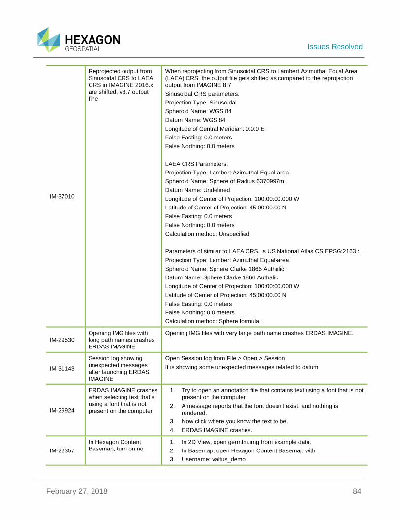
Issues Resolved
February 27, 2018 84
IM-37010
Reprojected output from Sinusoidal CRS to LAEA CRS in IMAGINE 2016.x are shifted, v8.7 output fine
When reprojecting from Sinusoidal CRS to Lambert Azimuthal Equal Area (LAEA) CRS, the output file gets shifted as compared to the reprojection output from IMAGINE 8.7
Sinusoidal CRS parameters:
Projection Type: Sinusoidal
Spheroid Name: WGS 84
Datum Name: WGS 84
Longitude of Central Meridian: 0:0:0 E
False Easting: 0.0 meters
False Northing: 0.0 meters
LAEA CRS Parameters:
Projection Type: Lambert Azimuthal Equal-area
Spheroid Name: Sphere of Radius 6370997m
Datum Name: Undefined
Longitude of Center of Projection: 100:00:00.000 W
Latitude of Center of Projection: 45:00:00.00 N
False Easting: 0.0 meters
False Northing: 0.0 meters
Calculation method: Unspecified
Parameters of similar to LAEA CRS, is US National Atlas CS EPSG:2163 :
Projection Type: Lambert Azimuthal Equal-area
Spheroid Name: Sphere Clarke 1866 Authalic
Datum Name: Sphere Clarke 1866 Authalic
Longitude of Center of Projection: 100:00:00.000 W
Latitude of Center of Projection: 45:00:00.00 N
False Easting: 0.0 meters
False Northing: 0.0 meters
Calculation method: Sphere formula.
IM-29530 Opening IMG files with long path names crashes ERDAS IMAGINE
Opening IMG files with very large path name crashes ERDAS IMAGINE.
IM-31143
Session log showing unexpected messages after launching ERDAS IMAGINE
Open Session log from File > Open > Session
It is showing some unexpected messages related to datum
IM-29924
ERDAS IMAGINE crashes when selecting text that's using a font that is not present on the computer
1. Try to open an annotation file that contains text using a font that is not present on the computer
2. A message reports that the font doesn't exist, and nothing is rendered.
3. Now click where you know the text to be.
4. ERDAS IMAGINE crashes.
IM-22357
In Hexagon Content Basemap, turn on no
1. In 2D View, open germtm.img from example data.
2. In Basemap, open Hexagon Content Basemap with
3. Username: valtus_demo
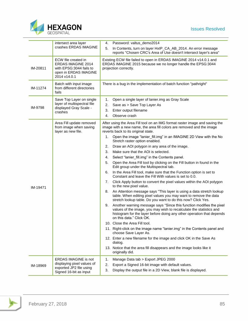
Issues Resolved
February 27, 2018 85
intersect area layer crashes ERDAS IMAGINE
4. Password: valtus_demo2014
5. In Contents, turn on layer HxIP_CA_AB_2014. An error message reports "Chosen CRC's Area of Use doesn't intersect layer's area"
IM-20811
ECW file created in ERDAS IMAGINE 2014 with EPSG:3044 fails to open in ERDAS IMAGINE 2014 v14.0.1
Existing ECW file failed to open in ERDAS IMAGINE 2014 v14.0.1 and ERDAS IMAGINE 2015 because we no longer handle the EPSG:3044 projection correctly.
IM-11274 Batch with input image from different directories fails
There is a bug in the implementation of batch function "pathright"
IM-9798
Save Top Layer on single layer of multispectral file displayed Gray Scale - crashes
1. Open a single layer of lanier.img as Gray Scale
2. Save as > Save Top Layer As
3. Enter output filename
4. Observe crash
IM-19471
Area Fill update removed from image when saving layer as new file.
After using the Area Fill tool on an IMG format raster image and saving the image with a new name, the area fill colors are removed and the image reverts back to its original state.
1. Open the image “lanier_fill.img” in an IMAGINE 2D View with the No Stretch raster option enabled.
2. Draw an AOI polygon in any area of the image.
3. Make sure that the AOI is selected.
4. Select “lanier_fill.img” in the Contents panel.
5. Open the Area Fill tool by clicking on the Fill button in found in the Edit group under the Multispectral tab.
6. In the Area Fill tool, make sure that the Function option is set to Constant and leave the Fill With values is set to 0.0.
7. Click Apply button to convert the pixel values within the AOI polygon to the new pixel value.
8. An Attention message says "This layer is using a data stretch lookup table. When editing pixel values you may want to remove the data stretch lookup table. Do you want to do this now? Click Yes.
9. Another warning message says “Since this function modifies the pixel values of the image, you may wish to recalculate the statistics and histogram for the layer before doing any other operation that depends on this data.” Click OK.
10. Close the Area Fill tool.
11. Right-click on the image name “lanier.img” in the Contents panel and choose Save Layer As.
12. Enter a new filename for the image and click OK in the Save As dialog.
13. Notice that the area fill disappears and the image looks like it originally did.
IM-18969
ERDAS IMAGINE is not displaying pixel values of exported JP2 file using Signed 16-bit as input
1. Manage Data tab > Export JPEG 2000
2. Export a Signed 16-bit image with default values.
3. Display the output file in a 2D View, blank file is displayed.
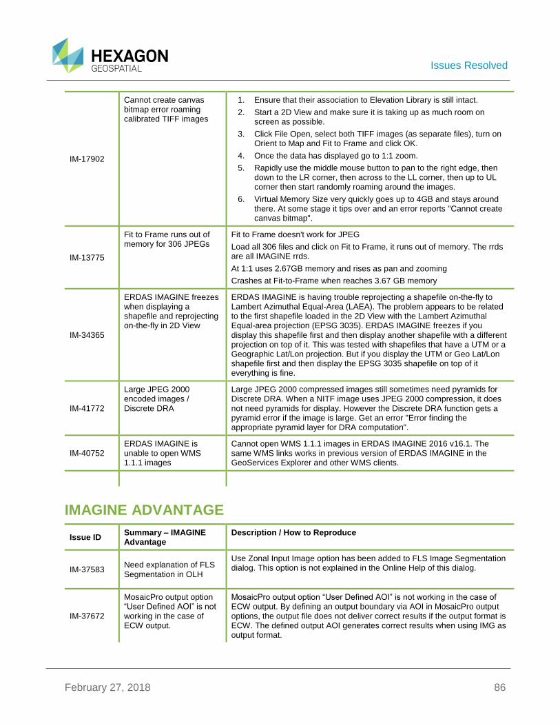
Issues Resolved
February 27, 2018 86
IM-17902
Cannot create canvas bitmap error roaming calibrated TIFF images
1. Ensure that their association to Elevation Library is still intact.
2. Start a 2D View and make sure it is taking up as much room on screen as possible.
3. Click File Open, select both TIFF images (as separate files), turn on Orient to Map and Fit to Frame and click OK.
4. Once the data has displayed go to 1:1 zoom.
5. Rapidly use the middle mouse button to pan to the right edge, then down to the LR corner, then across to the LL corner, then up to UL corner then start randomly roaming around the images.
6. Virtual Memory Size very quickly goes up to 4GB and stays around there. At some stage it tips over and an error reports "Cannot create canvas bitmap".
IM-13775
Fit to Frame runs out of memory for 306 JPEGs
Fit to Frame doesn't work for JPEG
Load all 306 files and click on Fit to Frame, it runs out of memory. The rrds are all IMAGINE rrds.
At 1:1 uses 2.67GB memory and rises as pan and zooming
Crashes at Fit-to-Frame when reaches 3.67 GB memory
IM-34365
ERDAS IMAGINE freezes when displaying a shapefile and reprojecting on-the-fly in 2D View
ERDAS IMAGINE is having trouble reprojecting a shapefile on-the-fly to Lambert Azimuthal Equal-Area (LAEA). The problem appears to be related to the first shapefile loaded in the 2D View with the Lambert Azimuthal Equal-area projection (EPSG 3035). ERDAS IMAGINE freezes if you display this shapefile first and then display another shapefile with a different projection on top of it. This was tested with shapefiles that have a UTM or a Geographic Lat/Lon projection. But if you display the UTM or Geo Lat/Lon shapefile first and then display the EPSG 3035 shapefile on top of it everything is fine.
IM-41772
Large JPEG 2000 encoded images / Discrete DRA
Large JPEG 2000 compressed images still sometimes need pyramids for Discrete DRA. When a NITF image uses JPEG 2000 compression, it does not need pyramids for display. However the Discrete DRA function gets a pyramid error if the image is large. Get an error "Error finding the appropriate pyramid layer for DRA computation".
IM-40752 ERDAS IMAGINE is unable to open WMS 1.1.1 images
Cannot open WMS 1.1.1 images in ERDAS IMAGINE 2016 v16.1. The same WMS links works in previous version of ERDAS IMAGINE in the GeoServices Explorer and other WMS clients.
IMAGINE ADVANTAGE
Issue ID Summary – IMAGINE Advantage
Description / How to Reproduce
IM-37583 Need explanation of FLS Segmentation in OLH
Use Zonal Input Image option has been added to FLS Image Segmentation dialog. This option is not explained in the Online Help of this dialog.
IM-37672
MosaicPro output option “User Defined AOI” is not working in the case of ECW output.
MosaicPro output option “User Defined AOI” is not working in the case of ECW output. By defining an output boundary via AOI in MosaicPro output options, the output file does not deliver correct results if the output format is ECW. The defined output AOI generates correct results when using IMG as output format.
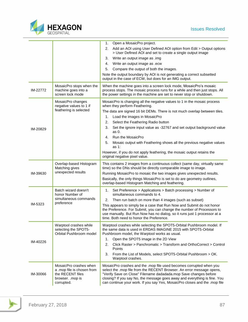
Issues Resolved
February 27, 2018 87
1. Open a MosaicPro project.
2. Add an AOI using User Defined AOI option from Edit > Output options > User Defined AOI and set to create a single output image
3. Write an output image as .img
4. Write an output image as .ecw
5. Compare the output of both the images.
Note the output boundary by AOI is not generating a correct subsetted output in the case of ECW, but does for an IMG output.
IM-22772 MosaicPro stops when the machine goes into a screen lock mode
When the machine goes into a screen lock mode, MosaicPro’s mosaic process stops. The mosaic process runs for a while and then just stops. All the power settings in the machine are set to never stop or shutdown.
IM-20829
MosaicPro changes negative values to 1 if feathering is selected
MosaicPro is changing all the negative values to 1 in the mosaic process when they perform Feathering.
The data are signed 16 bit DEMs. There is not much overlap between tiles.
1. Load the images in MosaicPro
2. Select the Feathering Radio button
3. Set the ignore input value as -32767 and set output background value as 0.
4. Run the MosaicPro
5. Mosaic output with Feathering shows all the previous negative values as 1:
However, if you do not apply feathering, the mosaic output retains the original negative pixel value.
IM-39630
Overlap-based Histogram Matching gives unexpected results
This contains 2 images from a continuous collect (same day, virtually same time) so the DNs should be directly comparable image to image.
Running MosaicPro to mosaic the two images gives unexpected results.
Basically, the only things MosaicPro is set to do are geometry outlines, overlap-based Histogram Matching and feathering.
IM-5323
Batch wizard doesn't honor Number of simultaneous commands preference
1. Set Preference > Applications > Batch processing > Number of simultaneous commands to 4.
2. Then run batch on more than 4 images (such as subset)
This appears to simply be a case that Run Now and Submit do not honor the Preference. For Submit, you can change the number of Processors to use manually. But Run Now has no dialog, so it runs just 1 processor at a time. Both need to honor the Preference.
IM-40226
Warptool crashes while selecting the SPOT5-Orbital Pushbroom model
Warptool crashes while selecting the SPOT5-Orbital Pushbroom model. If the same data is used in ERDAS IMAGINE 2015 with SPOT5-Orbital Pushbroom model, the Warptool works as usual.
1. Open the SPOT5 image in the 2D View
2. Click Raster > Panchromatic > Transform and OrthoCorrect > Control Points
3. From the List of Models, select SPOT5-Orbital Pushbroom > OK. Warptool crashes.
IM-30066
MosaicPro crashes when a .mop file is chosen from the RECENT files browser. .mop is corrupted.
MosaicPro crashes and the .mop file used becomes corrupted when you select the .mop file from the RECENT Browser. An error message opens, "Verify Save on Close" Filename dadadada.mop Save changes before closing? If you say No, the message goes away and everything is fine. You can continue your work. If you say Yes, MosaicPro closes and the .mop file
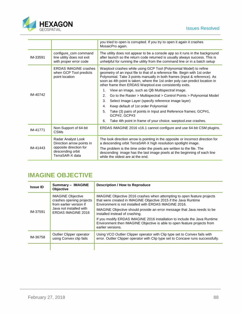
Issues Resolved
February 27, 2018 88
you tried to open is corrupted. If you try to open it again it crashes MosaicPro again.
IM-33591 configure_csm command line utility does not exit with proper error code
The utility does not appear to be a console app so it runs in the background after launch so the return code returned is usually always success. This is unhelpful for running the utility from the command line or in a batch setup
IM-40742
ERDAS IMAGINE crashes when GCP Tool predicts point location
Warptool crashes while using GCP Tool (Polynomial Model) to refine geometry of an input file to that of a reference file. Begin with 1st order Polynomial. Take 3 points manually in both frames (input & reference). As soon as 4th point is taken, where the 1st order poly can predict location in other frame then ERDAS Warptool.exe consistently exits.
1. View an image, such as QB Multispectral image.
2. Go to the Raster > Multispectral > Control Points > Polynomial Model
3. Select Image Layer (specify reference image layer)
4. Keep default of 1st order Polynomial
5. Take (3) pairs of points in Input and Reference frames; GCP#1, GCP#2, GCP#3
6. Take 4th point in frame of your choice. warptool.exe crashes.
IM-41771 Non-Support of 64-bit CSMs
ERDAS IMAGINE 2016 v16.1 cannot configure and use 64-bit CSM plugins.
IM-41443
Radar Analyst Look Direction arrow points in opposite direction for descending orbit TerraSAR-X data
The look direction arrow is pointing in the opposite or incorrect direction for a descending orbit TerraSAR-X high resolution spotlight image.
The problem is the time order the pixels are written to the file. The descending image has the last image pixels at the beginning of each line while the oldest are at the end.
IMAGINE OBJECTIVE
Issue ID Summary – IMAGINE Objective
Description / How to Reproduce
IM-37591
IMAGINE Objective crashes opening projects from earlier version if Java not installed with ERDAS IMAGINE 2016
IMAGINE Objective 2016 crashes when attempting to open feature projects that were created in IMAGINE Objective 2015 if the Java Runtime Environment is not installed with ERDAS IMAGINE 2016.
IMAGINE Objective should provide an error message that Java needs to be installed instead of crashing.
If you modify ERDAS IMAGINE 2016 installation to include the Java Runtime Environment then IMAGINE Objective is able to open feature projects from earlier versions.
IM-36758 Outlier Clipper operator using Convex clip fails
Using VCO Outlier Clipper operator with Clip type set to Convex fails with error. Outlier Clipper operator with Clip type set to Concave runs successfully.
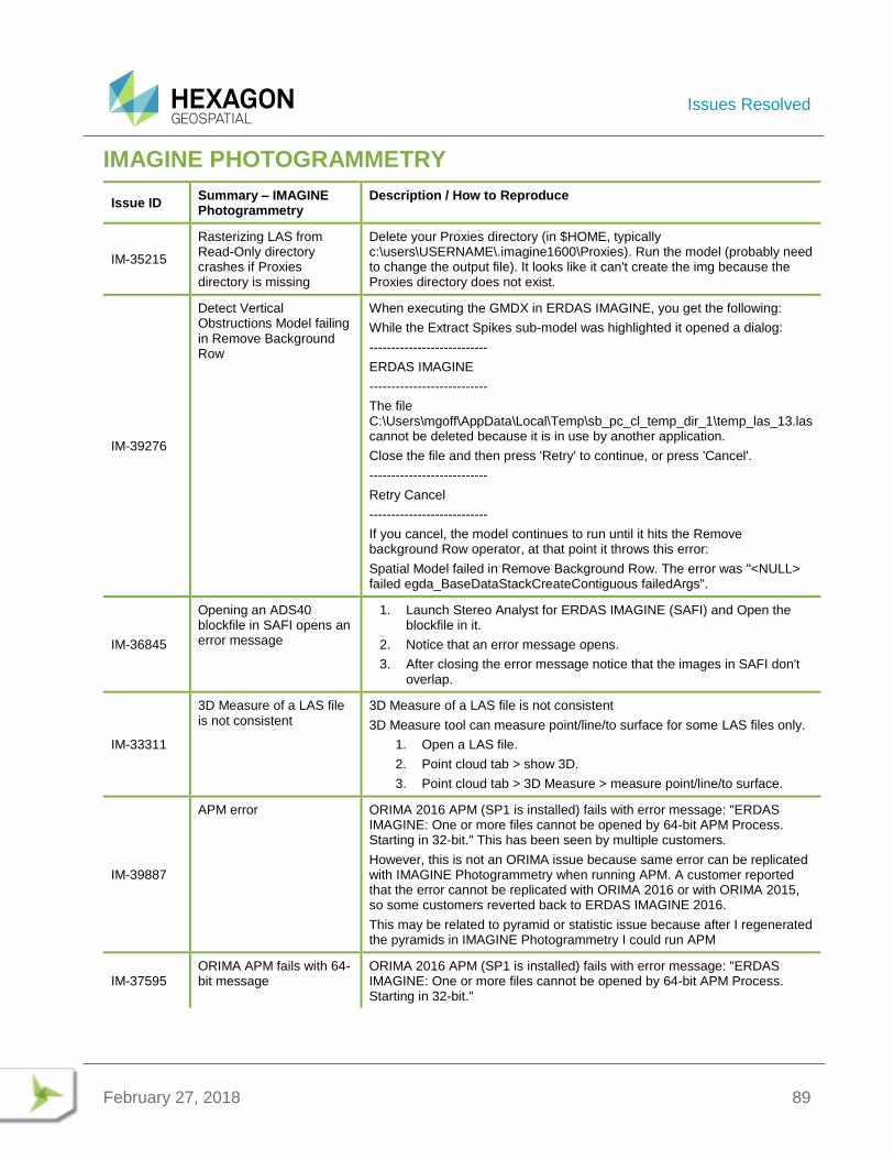
Issues Resolved
February 27, 2018 89
IMAGINE PHOTOGRAMMETRY
Issue ID Summary – IMAGINE Photogrammetry
Description / How to Reproduce
IM-35215
Rasterizing LAS from Read-Only directory crashes if Proxies directory is missing
Delete your Proxies directory (in $HOME, typically c:\users\USERNAME\.imagine1600\Proxies). Run the model (probably need to change the output file). It looks like it can't create the img because the Proxies directory does not exist.
IM-39276
Detect Vertical Obstructions Model failing in Remove Background Row
When executing the GMDX in ERDAS IMAGINE, you get the following:
While the Extract Spikes sub-model was highlighted it opened a dialog:
---------------------------
ERDAS IMAGINE
---------------------------
The file C:\Users\mgoff\AppData\Local\Temp\sb_pc_cl_temp_dir_1\temp_las_13.las cannot be deleted because it is in use by another application.
Close the file and then press 'Retry' to continue, or press 'Cancel'.
---------------------------
Retry Cancel
---------------------------
If you cancel, the model continues to run until it hits the Remove background Row operator, at that point it throws this error:
Spatial Model failed in Remove Background Row. The error was "<NULL> failed egda_BaseDataStackCreateContiguous failedArgs".
IM-36845
Opening an ADS40 blockfile in SAFI opens an error message
1. Launch Stereo Analyst for ERDAS IMAGINE (SAFI) and Open the blockfile in it.
2. Notice that an error message opens.
3. After closing the error message notice that the images in SAFI don't overlap.
IM-33311
3D Measure of a LAS file is not consistent
3D Measure of a LAS file is not consistent
3D Measure tool can measure point/line/to surface for some LAS files only.
1. Open a LAS file.
2. Point cloud tab > show 3D.
3. Point cloud tab > 3D Measure > measure point/line/to surface.
IM-39887
APM error ORIMA 2016 APM (SP1 is installed) fails with error message: "ERDAS IMAGINE: One or more files cannot be opened by 64-bit APM Process. Starting in 32-bit." This has been seen by multiple customers.
However, this is not an ORIMA issue because same error can be replicated with IMAGINE Photogrammetry when running APM. A customer reported that the error cannot be replicated with ORIMA 2016 or with ORIMA 2015, so some customers reverted back to ERDAS IMAGINE 2016.
This may be related to pyramid or statistic issue because after I regenerated the pyramids in IMAGINE Photogrammetry I could run APM
IM-37595 ORIMA APM fails with 64-bit message
ORIMA 2016 APM (SP1 is installed) fails with error message: "ERDAS IMAGINE: One or more files cannot be opened by 64-bit APM Process. Starting in 32-bit."
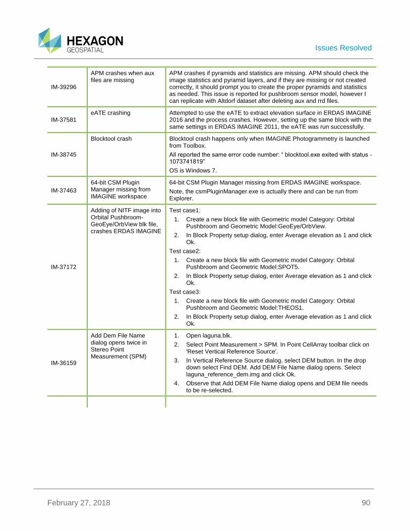
Issues Resolved
February 27, 2018 90
IM-39296
APM crashes when aux files are missing
APM crashes if pyramids and statistics are missing. APM should check the image statistics and pyramid layers, and if they are missing or not created correctly, it should prompt you to create the proper pyramids and statistics as needed. This issue is reported for pushbroom sensor model, however I can replicate with Altdorf dataset after deleting aux and rrd files.
IM-37581 eATE crashing Attempted to use the eATE to extract elevation surface in ERDAS IMAGINE
2016 and the process crashes. However, setting up the same block with the same settings in ERDAS IMAGINE 2011, the eATE was run successfully.
IM-38745
Blocktool crash Blocktool crash happens only when IMAGINE Photogrammetry is launched from Toolbox.
All reported the same error code number: “ blocktool.exe exited with status -1073741819”
OS is Windows 7.
IM-37463
64-bit CSM Plugin Manager missing from IMAGINE workspace
64-bit CSM Plugin Manager missing from ERDAS IMAGINE workspace.
Note, the csmPluginManager.exe is actually there and can be run from Explorer.
IM-37172
Adding of NITF image into Orbital Pushbroom-GeoEye/OrbView blk file, crashes ERDAS IMAGINE
Test case1:
1. Create a new block file with Geometric model Category: Orbital Pushbroom and Geometric Model:GeoEye/OrbView.
2. In Block Property setup dialog, enter Average elevation as 1 and click Ok.
Test case2:
1. Create a new block file with Geometric model Category: Orbital Pushbroom and Geometric Model:SPOT5.
2. In Block Property setup dialog, enter Average elevation as 1 and click Ok.
Test case3:
1. Create a new block file with Geometric model Category: Orbital Pushbroom and Geometric Model:THEOS1.
2. In Block Property setup dialog, enter Average elevation as 1 and click Ok.
IM-36159
Add Dem File Name dialog opens twice in Stereo Point Measurement (SPM)
1. Open laguna.blk.
2. Select Point Measurement > SPM. In Point CellArray toolbar click on 'Reset Vertical Reference Source'.
3. In Vertical Reference Source dialog, select DEM button. In the drop down select Find DEM. Add DEM File Name dialog opens. Select laguna_reference_dem.img and click Ok.
4. Observe that Add DEM File Name dialog opens and DEM file needs to be re-selected.
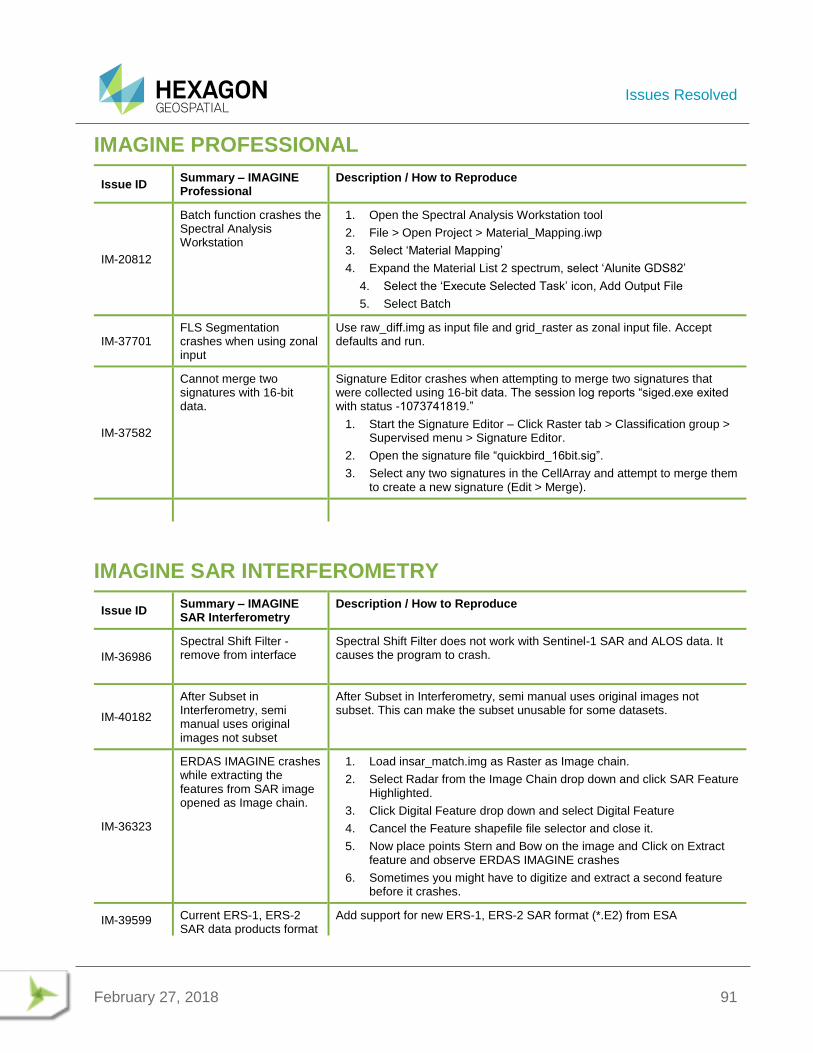
Issues Resolved
February 27, 2018 91
IMAGINE PROFESSIONAL
Issue ID Summary – IMAGINE Professional
Description / How to Reproduce
IM-20812
Batch function crashes the Spectral Analysis Workstation
1. Open the Spectral Analysis Workstation tool
2. File > Open Project > Material_Mapping.iwp
3. Select ‘Material Mapping’
4. Expand the Material List 2 spectrum, select ‘Alunite GDS82’
4. Select the ‘Execute Selected Task’ icon, Add Output File
5. Select Batch
IM-37701 FLS Segmentation crashes when using zonal input
Use raw_diff.img as input file and grid_raster as zonal input file. Accept defaults and run.
IM-37582
Cannot merge two signatures with 16-bit data.
Signature Editor crashes when attempting to merge two signatures that were collected using 16-bit data. The session log reports “siged.exe exited with status -1073741819.”
1. Start the Signature Editor – Click Raster tab > Classification group > Supervised menu > Signature Editor.
2. Open the signature file “quickbird_16bit.sig”.
3. Select any two signatures in the CellArray and attempt to merge them to create a new signature (Edit > Merge).
IMAGINE SAR INTERFEROMETRY
Issue ID Summary – IMAGINE SAR Interferometry
Description / How to Reproduce
IM-36986
Spectral Shift Filter - remove from interface
Spectral Shift Filter does not work with Sentinel-1 SAR and ALOS data. It causes the program to crash.
IM-40182
After Subset in Interferometry, semi manual uses original images not subset
After Subset in Interferometry, semi manual uses original images not subset. This can make the subset unusable for some datasets.
IM-36323
ERDAS IMAGINE crashes while extracting the features from SAR image opened as Image chain.
1. Load insar_match.img as Raster as Image chain.
2. Select Radar from the Image Chain drop down and click SAR Feature Highlighted.
3. Click Digital Feature drop down and select Digital Feature
4. Cancel the Feature shapefile file selector and close it.
5. Now place points Stern and Bow on the image and Click on Extract feature and observe ERDAS IMAGINE crashes
6. Sometimes you might have to digitize and extract a second feature before it crashes.
IM-39599 Current ERS-1, ERS-2 SAR data products format
Add support for new ERS-1, ERS-2 SAR format (*.E2) from ESA
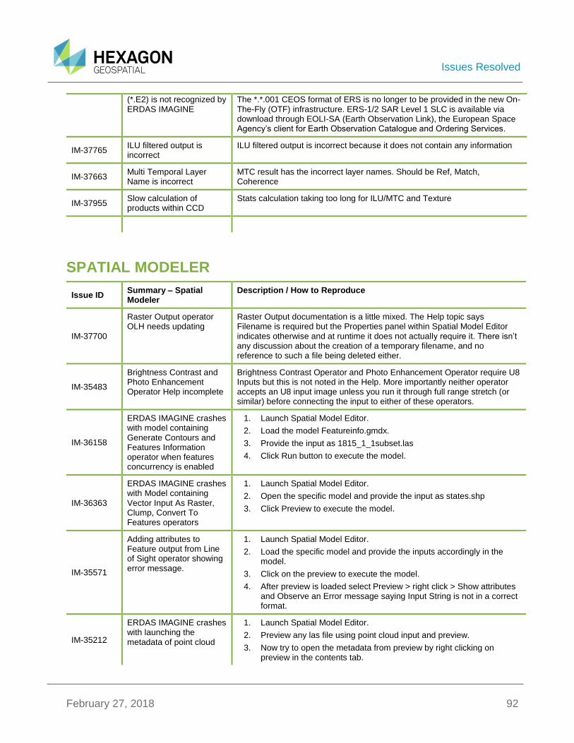
Issues Resolved
February 27, 2018 92
(*.E2) is not recognized by ERDAS IMAGINE
The *.*.001 CEOS format of ERS is no longer to be provided in the new On-The-Fly (OTF) infrastructure. ERS-1/2 SAR Level 1 SLC is available via download through EOLI-SA (Earth Observation Link), the European Space Agency’s client for Earth Observation Catalogue and Ordering Services.
IM-37765 ILU filtered output is incorrect
ILU filtered output is incorrect because it does not contain any information
IM-37663 Multi Temporal Layer Name is incorrect
MTC result has the incorrect layer names. Should be Ref, Match, Coherence
IM-37955 Slow calculation of products within CCD
Stats calculation taking too long for ILU/MTC and Texture
SPATIAL MODELER
Issue ID Summary – Spatial Modeler
Description / How to Reproduce
IM-37700
Raster Output operator OLH needs updating
Raster Output documentation is a little mixed. The Help topic says Filename is required but the Properties panel within Spatial Model Editor indicates otherwise and at runtime it does not actually require it. There isn’t any discussion about the creation of a temporary filename, and no reference to such a file being deleted either.
IM-35483
Brightness Contrast and Photo Enhancement Operator Help incomplete
Brightness Contrast Operator and Photo Enhancement Operator require U8 Inputs but this is not noted in the Help. More importantly neither operator accepts an U8 input image unless you run it through full range stretch (or similar) before connecting the input to either of these operators.
IM-36158
ERDAS IMAGINE crashes with model containing Generate Contours and Features Information operator when features concurrency is enabled
1. Launch Spatial Model Editor.
2. Load the model Featureinfo.gmdx.
3. Provide the input as 1815_1_1subset.las
4. Click Run button to execute the model.
IM-36363
ERDAS IMAGINE crashes with Model containing Vector Input As Raster, Clump, Convert To Features operators
1. Launch Spatial Model Editor.
2. Open the specific model and provide the input as states.shp
3. Click Preview to execute the model.
IM-35571
Adding attributes to Feature output from Line of Sight operator showing error message.
1. Launch Spatial Model Editor.
2. Load the specific model and provide the inputs accordingly in the model.
3. Click on the preview to execute the model.
4. After preview is loaded select Preview > right click > Show attributes and Observe an Error message saying Input String is not in a correct format.
IM-35212
ERDAS IMAGINE crashes with launching the metadata of point cloud
1. Launch Spatial Model Editor.
2. Preview any las file using point cloud input and preview.
3. Now try to open the metadata from preview by right clicking on preview in the contents tab.
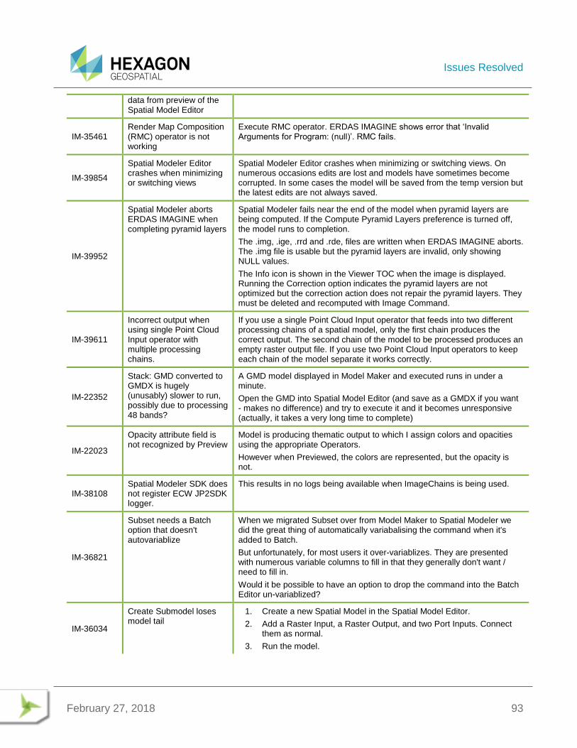
Issues Resolved
February 27, 2018 93
data from preview of the Spatial Model Editor
IM-35461 Render Map Composition (RMC) operator is not working
Execute RMC operator. ERDAS IMAGINE shows error that ‘Invalid Arguments for Program: (null)’. RMC fails.
IM-39854
Spatial Modeler Editor crashes when minimizing or switching views
Spatial Modeler Editor crashes when minimizing or switching views. On numerous occasions edits are lost and models have sometimes become corrupted. In some cases the model will be saved from the temp version but the latest edits are not always saved.
IM-39952
Spatial Modeler aborts ERDAS IMAGINE when completing pyramid layers
Spatial Modeler fails near the end of the model when pyramid layers are being computed. If the Compute Pyramid Layers preference is turned off, the model runs to completion.
The .img, .ige, .rrd and .rde, files are written when ERDAS IMAGINE aborts. The .img file is usable but the pyramid layers are invalid, only showing NULL values.
The Info icon is shown in the Viewer TOC when the image is displayed. Running the Correction option indicates the pyramid layers are not optimized but the correction action does not repair the pyramid layers. They must be deleted and recomputed with Image Command.
IM-39611
Incorrect output when using single Point Cloud Input operator with multiple processing chains.
If you use a single Point Cloud Input operator that feeds into two different processing chains of a spatial model, only the first chain produces the correct output. The second chain of the model to be processed produces an empty raster output file. If you use two Point Cloud Input operators to keep each chain of the model separate it works correctly.
IM-22352
Stack: GMD converted to GMDX is hugely (unusably) slower to run, possibly due to processing 48 bands?
A GMD model displayed in Model Maker and executed runs in under a minute.
Open the GMD into Spatial Model Editor (and save as a GMDX if you want - makes no difference) and try to execute it and it becomes unresponsive (actually, it takes a very long time to complete)
IM-22023
Opacity attribute field is not recognized by Preview
Model is producing thematic output to which I assign colors and opacities using the appropriate Operators.
However when Previewed, the colors are represented, but the opacity is not.
IM-38108 Spatial Modeler SDK does not register ECW JP2SDK logger.
This results in no logs being available when ImageChains is being used.
IM-36821
Subset needs a Batch option that doesn't autovariablize
When we migrated Subset over from Model Maker to Spatial Modeler we did the great thing of automatically variabalising the command when it's added to Batch.
But unfortunately, for most users it over-variablizes. They are presented with numerous variable columns to fill in that they generally don't want / need to fill in.
Would it be possible to have an option to drop the command into the Batch Editor un-variablized?
IM-36034
Create Submodel loses model tail
1. Create a new Spatial Model in the Spatial Model Editor.
2. Add a Raster Input, a Raster Output, and two Port Inputs. Connect them as normal.
3. Run the model.
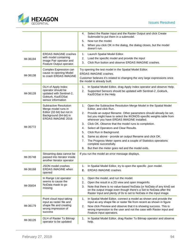
Issues Resolved
February 27, 2018 94
4. Select the Raster Input and the Raster Output and click Create Submodel to put them in a submodel.
5. Now run the model.
6. When you click OK in the dialog, the dialog closes, but the model doesn't run.
IM-36194
ERDAS IMAGINE crashes with model containing Image Pair operator and Feature Output operator.
1. Launch Spatial Model Editor.
2. Load the specific model and provide the input
3. Click Run button and observe ERDAS IMAGINE crashes.
IM-36138
Complex Expression can cause re-opening Model to crash ERDAS IMAGINE
Try opening the test model in the Spatial Model Editor.
ERDAS IMAGINE crashes.
Customer believes it’s related to changing the very large expressions once the model is already built.
IM-36128
OLH of Apply Index operator should be updated with Sentinel-2, Gokturk, KazEOSat sensor information
1. In Spatial Model Editor, drag Apply Index operator and observe Help.
2. Supported Sensors should be updated with Sentinel-2 ,Gokturk, KazEOSat in the Help.
IM-35772
Subtractive Resolution Merge model runs in Editor (32-bit) but not in Background (64-bit) in ERDAS IMAGINE 2016
1. Open the Subtractive Resolution Merge Model in the Spatial Model Editor, and click Run.
2. Provide an output filename. Other parameters should already be set, but you might have to select the IKONOS-specific weights table from wherever you have ERDAS IMAGINE installed.
3. Click OK. Observe that the model runs to completion.
4. Select all Operators and Clear Results.
5. Click Run in Background.
6. Same as above - provide an output filename and click OK.
7. The Progress Meter opens and a couple of Statistics operations complete successfully.
8. But then the meter goes red and the model exits.
IM-35748 Streaming data cannot be passed into Iterator inside another Iterator operator
If you run the model an error message displays.
IM-36168 JSON model crashes ERDAS IMAGINE when opened
1. In Spatial Model Editor, try to open the specific .json model.
2. ERDAS IMAGINE crashes.
IM-35834
In Range List operator seems to cause the NoData mask to go missing
1. Open the model, and run the model.
2. Open the result in a 2D view and open ImageInfo.
3. Note that there is no value-based NoData (or NoData of any kind) set on the output image even though there's a Set to NoData after the Raster Input and plenty of 0s to set to NoData in the input image.
IM-36179
Point cloud input taking input as raster file and shape file and creating wrong impression of success
1. In Spatial Model Editor, connect a model as shown and provide the input as any shape file or raster file from recent as shown in figure
2. Now click Preview and observe that it is showing success. This is wrong impression to the user and not the case with Raster input and Feature input operators.
IM-36126 OLH of Raster To Bitmap operator to be updated
1. In Spatial Model Editor, drag Raster To Bitmap operator and observe help.

Issues Resolved
February 27, 2018 95
Update the Help in these places:
* Show all ports, Default ports figures
* Is GreyScale port should be added in connections table
IM-36127
OLH of Get DRA Params should be updated
1. In Spatial Model Editor, drag Get DRA Params operator and observe help
Update the Help topic:
Show all ports
Default ports figures
IM-36217
EML numerical entry can be broken with feature input and Windows non-English language format
This problem is not seen with Windows non-English language format in ERDAS IMAGINE 2015, and is not seen in ERDAS IMAGINE 2016 with Windows English language format. The problem is not observed with raster input in Spatial Modeler.
To reproduce:
1. Windows > Control Panel > Region and Language > Format > Italian > Apply
2. Restart ERDAS IMAGINE
3. Session log should display 'Locale: it-IT'. At this point EML does not honor the decimal symbol comma ( , ). However Windows does (for example. Calculator).
4. Open Spatial model ‘test_feature_define.gmdx’, run Preview, select the shapefile ‘thevillagesparcelssubset_4326.shp’. This introduces a change in the EML behavior where the comma decimal symbol ( , ) is used in EML.
5. Open a ‘Define Processing Area’ operator > open Cell Size Rule pulldown menu > select Specify. In X file type 1,50 <cr>.
6. The value is truncated to 1,00.
IM-36216
Spatial Modeler runs out of memory and crashes ERDAS IMAGINE
Model using Iterator operator with an embedded Iterator operator runs out of memory and crashes ERDAS IMAGINE after processing ~25 of 48 images. Raster operators include Zonal Mean, Direct Lookup, and Stack Layers. Same model completes successfully when Run in Background.
IM-36093
Screenshot of List operator in OLH and User Interface is not in sync
Screenshot of List operator in OLH is not in sync with Value1 input port
OLH needs update of operator screenshot, displaying Value1 input port as only the required port.
IM-35172
OptimizePyramidInfo takes a long time if there are many files in the directory
1. Copy the image to a directory that has LOTS of files in it, for example over 4000 files.
2. Run the CreateRSETs operator on the image in that directory.
It takes a long time for the operator to actually complete execution after the meters shows that the RSETs have been created.
IM-35550
Existing data not found on port (Expression)
After modifying a model and saving it, when trying to open, an error reported “Existing data not found on port (Expression)”.
Open the model. Simply drag and drop to the model an Expression operator, don't attach to anything, don't provide any expression. Save your model. Then try to open again.
IM-35324
ERDAS IMAGINE crashes with model containing Image Pair and Image Pair Information operators
1. Load the model in the Spatial Model Editor.
2. Provide the Raster inputs
3. Click Preview to execute the model and observe ERDAS IMAGINE crashes.
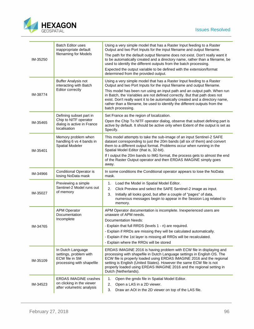
Issues Resolved
February 27, 2018 96
IM-35250
Batch Editor uses inappropriate default filenaming for Models
Using a very simple model that has a Raster Input feeding to a Raster Output and two Port Inputs for the input filename and output filename.
The path for the default output filename does not exist. Don't really want it to be automatically created and a directory name, rather than a filename, be used to identify the different outputs from the batch processing.
Expected the output variable to be defined with the extension/format determined from the provided output.
IM-38774
Buffer Analysis not interacting with Batch Editor correctly
Using a very simple model that has a Raster Input feeding to a Raster Output and two Port Inputs for the input filename and output filename.
This model has been run using an input path and an output path. When run in Batch, the Variables are not defined correctly. But that path does not exist. Don't really want it to be automatically created and a directory name, rather than a filename, be used to identify the different outputs from the batch processing.
IM-35465
Defining subset part in Chip to NITF operator dialog is active in France localisation
Set France as the region of localization.
Open the Chip To NITF operator dialog, observe that subset defining part is active by default. It should be active only when Extent of the output is set as Specify.
IM-35401
Memory problem when handling 6 vs 4 bands in Spatial Modeler
This model attempts to take the sub-image of an input Sentinel-2 SAFE dataset corresponding to just the 20m bands (all six of them) and convert them to a different output format. Problems occur when running in the Spatial Model Editor (that is, 32-bit).
If I output the 20m bands to IMG format, the process gets to almost the end of the Raster Output operator and then ERDAS IMAGINE simply goes away.
IM-34966 Conditional Operator is losing NoData mask
In some conditions the Conditional operator appears to lose the NoData mask.
IM-35027
Previewing a simple Sentinel-2 Model runs out of memory
1. Load the Model in Spatial Model Editor.
2. Click Preview and select the SAFE Sentinel-2 image as input.
3. Initially all looks good, but after a couple of "pages" of data, numerous messages begin to appear in the Session Log related to memory.
IM-34765
APM Operator Documentation Incomplete
APM Operator documentation is incomplete. Inexperienced users are unaware of APM needs.
Documentation Needs:
- Explain that full RRDS (levels 1 - n) are required.
- Explain if RRDs are missing they will be calculated automatically.
- Explain if the 1st layer is missing all RRDs will be recalculated.
- Explain where the RRDs will be stored
IM-35109
In Dutch Language settings, problem with ECW file in SM processing with shapefile
ERDAS IMAGINE 2016 is having problem with ECW file in displaying and processing with shapefile in Dutch Language settings in English OS. The ECW file is properly loaded using ERDAS IMAGINE 2016 and the regional setting is English (United States). However the same ECW file is not properly loaded using ERDAS IMAGINE 2016 and the regional setting in Dutch (Netherlands).
IM-34523
ERDAS IMAGINE crashes on clicking in the viewer after volumetric analysis
1. Open the gmdx file in Spatial Model Editor.
2. Open a LAS in a 2D viewer.
3. Draw an AOI in the 2D viewer on top of the LAS file.

Issues Resolved
February 27, 2018 97
with metadata of preview launched.
4. Give the same LAS file as an input to gmdx.
5. In the volume boundary port of the Point Cloud Measure Volume operator give Viewer as option and run the preview.
6. Right click on the Preview layer in the Contents panel and select *Show Attributes*.
7. With the AOI in the viewer selected, go to the Point Cloud tab and select *Load* from the *Boundary* drop down in the *Volumetric Analysis* group.
8. Click the Compute button to start the analysis.
9. Select the attributes table of the preview layer.
10. Click in the 2D viewer within the AOI. ERDAS IMAGINE crashes.
IM-34384 Can no longer really delete default values from a model
If a port the aliased port is connected to has a default value
IM-34457
Create Geospatial PDF operator does not add the extension to the output file name
Create simple model with Create Geospatial PDF operator. Enter the output file name without extension. It should automatically add extension pdf if not already provided.
IM-34222
Stream output from Merge Features if passed to Measure Area operator would crash ERDAS IMAGINE.
1. Open the specific model and give the shapefile as input.
2. Click the Preview button. Notice that ERDAS IMAGINE crashes.
If a Features Output operator is introduced between Merge features and Measure Area operators then no such issue exists.
IM-34528
Image Info reports skip of 4 even though Stats operator was set to 1
1. Open the specific model in the Spatial Model Editor.
2. Note that the Statistics Operator prior to Raster Output is set to a Skip of 1.
3. Run.
4. Open the resulting image in a 2D View and open ImageInfo.
5. Note that the skip factor is reported as 4 x 4.
IM-33840
Clicking Help button on the smguiprocess dialog gets an error (no help)
1. Create a Spatial Model with at least one input port.
2. Save the model.
3. Select Launch Spatial Model under the Spatial Model Editor dropdown in the Common group on the Toolbox tab.
4. Select the model you just saved.
5. A dialog opens for you to enter values for the input port.
6. Click the Help button.
7. Error message opens.
IM-33511
Create Temp Filename with Extensions causes Create Geospatial PDF to fail
1. Open the model and click Run.
2. Specify an output PDF filename and OK.
3. Wait for model to successfully finish.
4. On the first Create Temp Filename operator, specify an Extension of .img
5. Click Run again. Click yes, you want to delete the existing output file.
6. Click OK in the autogenerated dialog.
7. Executing the Create Geospatial PDF operator will fail.
IM-33459 Need to properly handle Vertical Coordinate
No Vertical CRS: should convert the features from 3D to 2D.

Issues Resolved
February 27, 2018 98
Reference Systems for Attach Vertical CRS Operator
1 Vertical CRS: should update the vertical CRS of the primary geometry field
N Vertical CRSs: if there are not 'N' geometry fields, throw a mismatched list exception. If there are 'N' geometry fields apply each item in the list to the corresponding geometry field.
IM-39655
Preview crashes if you create a submodel while previewing
1. Create a Raster Input - Preview model
2. Add a convolve operator with some custom matrix to the raster input and add the result as an additional port.
3. Run Preview
4. While the Preview is running select the custom matrix and convolve operator and create a sub-model.
IM-39239
excludeStatsValues being persisted as EGDA_RASTER_OBJECT when excluding only NODATA values
Case 1 (using LayerExcludedStatsValues() in eimg_Stats.cpp)
*Open air-photo-1.img in ImageInfo and confirm that it has value-based persisted NODATA.*
1. Create a Spatial Model with only RasterIn and RasterOut.
2. Set air-photo-1.img as the input.
3. For the output file select JPEG 2000 for the "Files of type" and give it a file name.
4. Run the model.
5. Use HFAView to look at the Statistics Parameters in the .aux file created for your output .jp2 file. The ExcludedValues have a datatype of EGDA_TYPE_U8 and an objecttype of EGDA_RASTER_OBJECT.
*Do NOT delete the output from this workflow because you will need it for Case 2."
*Close ERDAS IMAGINE between Case 1 and Case 2 to make sure that there's no caching of the statistics for the .jp2 file*
Case 2 (using LayerExcludedStatsValues() in Statistics.cpp)
1. Rename the .aux file created for the output .jp2 in Case 1.
2. Open the .jp2 file output from Case 1 in ImageInfo and confirm that it has mask-based persisted NODATA and *no statistics*.
3. Create a Spatial Model as in step 1 in Case 1.
4. Set the .jp2 file output from Case 1 as the input.
5. For the output file specify an .img file.
6. Run the model.
7. Use HFAView to look at the Statistics Parameters in the .img file. The ExcludedValues have a datatype of EGDA_TYPE_U8 and an objecttype of EGDA_RASTER_OBJECT.
IM-39334
Oblique Stereographic EPSG code not working for Geodetic Reproject Raster service
When the Geodetic Reproject Raster service (spatial model) is called using an Oblique Stereographic EPSG code, an error message displays.
IM-39330
South Polar Stereographic EPSG code not working for Geodetic Reproject Raster service
When the Geodetic Reproject Raster service (spatial model) is called using a South Polar Stereographic EPSG code, an error message displays.
IM-39213 MrSID DLL reporting persisted NODATA value for images without Alpha
MrSID file does not have NODATA (modeler didn't ever deal with NODATA). But if you open this image in ImageInfo and look at the "NODATA Persistence" on the "Pixel data" tab, it shows "Value(0)".
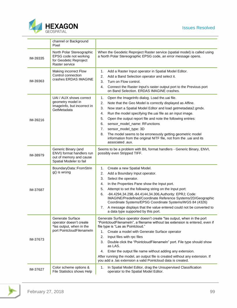
Issues Resolved
February 27, 2018 99
channel or Background Pixel
IM-39335
North Polar Stereographic EPSG code not working for Geodetic Reproject Raster service
When the Geodetic Reproject Raster service (spatial model) is called using a North Polar Stereographic EPSG code, an error message opens.
IM-39363
Making incorrect Flow Control connection crashes ERDAS IMAGINE
1. Add a Raster Input operator in Spatial Model Editor.
2. Add a Band Selection operator and select it.
3. Turn on Flow control.
4. Connect the Raster Input's raster output port to the Previous port on Band Selection. ERDAS IMAGINE crashes.
IM-39216
UAI / AUX shows correct geometry model in ImageInfo, but incorrect in GetMetadata
1. Open the ImageInfo dialog. Load the.uai file.
2. Note that the Geo Model is correctly displayed as Affine.
3. Now start a Spatial Model Editor and load getmetadata2.gmdx.
4. Run the model specifying the.uai file as an input image.
5. Open the output report file and note the following entries:
6. sensor_model_name: RFunctions
7. sensor_model_type: 3D
8. The model seems to be erroneously getting geometric model information from the original NITF file, not from the .uai and its associated .aux.
IM-38979
Generic Binary (and ENVI) format handlers run out of memory and cause Spatial Modeler to fail
Seems to be a problem with BIL format handlers - Generic Binary, ENVI, possibly even Stripped TIFF.
IM-37687
BoundaryData::FromString() is wrong
1. Create a new Spatial Model.
2. Add a Boundary Input operator.
3. Select the operator.
4. In the Properties Pane show the Input port.
5. Attempt to set the following string on the Input port:
6. -84.4294,34.298,-84.4144,34.306,Authority: EPRJ; Code: IMAGINE/Predefined/Coordinate Reference Systems/2D/Geographic Coordinate Systems/EPSG Coordinate Systems/WGS 84 (4326)
7. A message displays that the value entered could not be converted to a data type supported by this port.
IM-37673
Generate Surface operator doesn’t create *las output, when in the port PointcloudFilenameIn
Generate Surface operator doesn’t create *las output, when in the port “PointcloudFilenameIn”, a filename without las extension is entered, even if file type is “Las as Pointcloud.”
1. Create a model with Generate Surface operator
2. Input files with rpc files
3. Double click the “PointcloudFilenameIn” port. File type should show as LAS.
4. Enter the output file name without adding any extension.
After running the model, an output file is created without any extension. If you add a .las extension a valid Pointcloud data is created.
IM-37627 Color scheme options & File Statistics shows Help
1. In Spatial Model Editor, drag the Unsupervised Classification operator to the Spatial Model Editor.
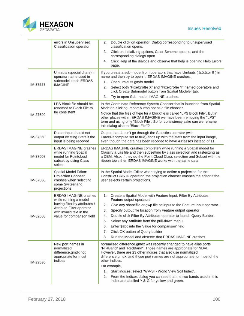
Issues Resolved
February 27, 2018 100
errors in Unsupervised Classification operator
2. Double click on operator. Dialog corresponding to unsupervised classification opens.
3. Click on Initializing options, Color Scheme options, and the corresponding dialogs open.
4. Click Help of the dialogs and observe that help is opening Help Errors page.
IM-37557
Umlauts (special chars) in operator name used in submodel crash ERDAS IMAGINE
If you create a sub-model from operators that have Umlauts ( ä,ö,ü,or ß ) in name and then try to open it, ERDAS IMAGINE crashes.
1. Open umlauts.gmdx model
2. Select both “Pixelgröße X” and “Pixelgröße Y” named operators and click Create Submodel button from Spatial Modeler tab.
3. Try to open Sub-model. IMAGINE crashes.
IM-37599
LPS Block file should be renamed to Block File to be consistent
In the Coordinate Reference System Chooser that is launched from Spatial Modeler, clicking Import button opens a file chooser.
Notice that the files of type for a blockfile is called "LPS Block File". But in other places within ERDAS IMAGINE we have been removing the "LPS" term and using only "Block File". So for consistency sake can we rename this dialog also to "Block File"?
IM-37360 RasterInput should not output existing Stats if the input is being recoded
Output that doesn't go through the Statistics operator (with ForceRecompute set to true) ends up with the stats from the input image, even though the data has been recoded to have 4 classes instead of 11.
IM-37608
ERDAS IMAGINE crashes while running Spatial model for Pointcloud subset by using Class select
ERDAS IMAGINE crashes completely while running a Spatial model for Classify a Las file and then subsetting by class selection and rasterizing as a DEM. Also, if they do the Point Cloud Class selection and Subset with the ribbon tools then ERDAS IMAGINE works with the same data.
IM-37068
Spatial Model Editor: Projection Chooser crashes when selecting some Switzerland projections
In the Spatial Model Editor when trying to define a projection for the Construct CRS ID operator, the projection chooser crashes the editor if the user selects certain projections.
IM-32688
ERDAS IMAGINE crashes while running a model having filter by attributes / Attribute Filter operator with invalid text in the value for comparison field
1. Create a Spatial Model with Feature Input, Filter By Attributes, Feature output operators.
2. Give any shapefile or gwp file as input to the Feature Input operator.
3. Specify output file location from Feature output operator
4. Double click Filter By Attributes operator to launch Query Builder.
5. Select any Attribute from the pull-down menu.
6. Enter $abc into the 'value for comparison' field
7. Click OK button of Query builder
8. Run the Model and observe that ERDAS IMAGINE crashes
IM-23580
New port names in normalized difference.gmdx not appropriate for most indices
normalized difference.gmdx was recently changed to have alias ports "NIRBand" and "RedBand". Those names are appropriate for NDVI. However, there are 23 other indices that also use normalized difference.gmdx, and those port names are not appropriate for most of the other indices.
For example,
1. Start indices, select "WV-SI - World View Soil Index".
2. From the Indices dialog you can see that the two bands used in this index are labelled Y & G for yellow and green.
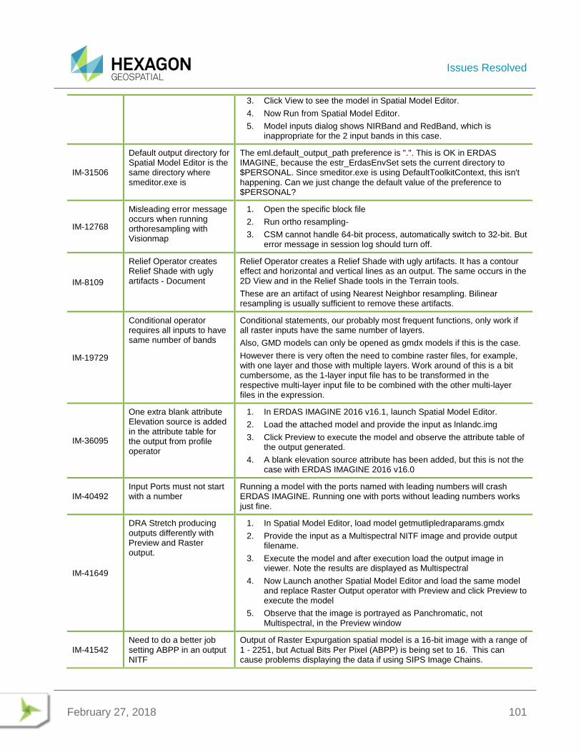
Issues Resolved
February 27, 2018 101
3. Click View to see the model in Spatial Model Editor.
4. Now Run from Spatial Model Editor.
5. Model inputs dialog shows NIRBand and RedBand, which is inappropriate for the 2 input bands in this case.
IM-31506
Default output directory for Spatial Model Editor is the same directory where smeditor.exe is
The eml.default_output_path preference is ".". This is OK in ERDAS IMAGINE, because the estr_ErdasEnvSet sets the current directory to $PERSONAL. Since smeditor.exe is using DefaultToolkitContext, this isn't happening. Can we just change the default value of the preference to $PERSONAL?
IM-12768
Misleading error message occurs when running orthoresampling with Visionmap
1. Open the specific block file
2. Run ortho resampling-
3. CSM cannot handle 64-bit process, automatically switch to 32-bit. But error message in session log should turn off.
IM-8109
Relief Operator creates Relief Shade with ugly artifacts - Document
Relief Operator creates a Relief Shade with ugly artifacts. It has a contour effect and horizontal and vertical lines as an output. The same occurs in the 2D View and in the Relief Shade tools in the Terrain tools.
These are an artifact of using Nearest Neighbor resampling. Bilinear resampling is usually sufficient to remove these artifacts.
IM-19729
Conditional operator requires all inputs to have same number of bands
Conditional statements, our probably most frequent functions, only work if all raster inputs have the same number of layers.
Also, GMD models can only be opened as gmdx models if this is the case.
However there is very often the need to combine raster files, for example, with one layer and those with multiple layers. Work around of this is a bit cumbersome, as the 1-layer input file has to be transformed in the respective multi-layer input file to be combined with the other multi-layer files in the expression.
IM-36095
One extra blank attribute Elevation source is added in the attribute table for the output from profile operator
1. In ERDAS IMAGINE 2016 v16.1, launch Spatial Model Editor.
2. Load the attached model and provide the input as lnlandc.img
3. Click Preview to execute the model and observe the attribute table of the output generated.
4. A blank elevation source attribute has been added, but this is not the case with ERDAS IMAGINE 2016 v16.0
IM-40492 Input Ports must not start with a number
Running a model with the ports named with leading numbers will crash ERDAS IMAGINE. Running one with ports without leading numbers works just fine.
IM-41649
DRA Stretch producing outputs differently with Preview and Raster output.
1. In Spatial Model Editor, load model getmutlipledraparams.gmdx
2. Provide the input as a Multispectral NITF image and provide output filename.
3. Execute the model and after execution load the output image in viewer. Note the results are displayed as Multispectral
4. Now Launch another Spatial Model Editor and load the same model and replace Raster Output operator with Preview and click Preview to execute the model
5. Observe that the image is portrayed as Panchromatic, not Multispectral, in the Preview window
IM-41542 Need to do a better job setting ABPP in an output NITF
Output of Raster Expurgation spatial model is a 16-bit image with a range of 1 - 2251, but Actual Bits Per Pixel (ABPP) is being set to 16. This can cause problems displaying the data if using SIPS Image Chains.
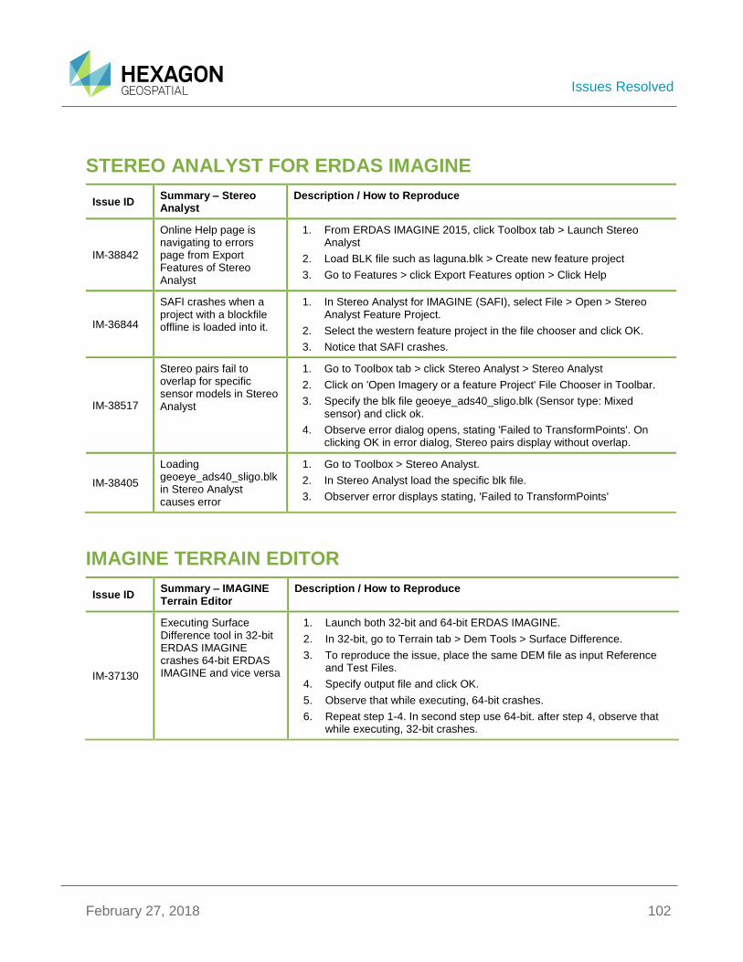
Issues Resolved
February 27, 2018 102
STEREO ANALYST FOR ERDAS IMAGINE
Issue ID Summary – Stereo Analyst
Description / How to Reproduce
IM-38842
Online Help page is navigating to errors page from Export Features of Stereo Analyst
1. From ERDAS IMAGINE 2015, click Toolbox tab > Launch Stereo Analyst
2. Load BLK file such as laguna.blk > Create new feature project
3. Go to Features > click Export Features option > Click Help
IM-36844
SAFI crashes when a project with a blockfile offline is loaded into it.
1. In Stereo Analyst for IMAGINE (SAFI), select File > Open > Stereo Analyst Feature Project.
2. Select the western feature project in the file chooser and click OK.
3. Notice that SAFI crashes.
IM-38517
Stereo pairs fail to overlap for specific sensor models in Stereo Analyst
1. Go to Toolbox tab > click Stereo Analyst > Stereo Analyst
2. Click on 'Open Imagery or a feature Project' File Chooser in Toolbar.
3. Specify the blk file geoeye_ads40_sligo.blk (Sensor type: Mixed sensor) and click ok.
4. Observe error dialog opens, stating 'Failed to TransformPoints'. On clicking OK in error dialog, Stereo pairs display without overlap.
IM-38405
Loading geoeye_ads40_sligo.blk in Stereo Analyst causes error
1. Go to Toolbox > Stereo Analyst.
2. In Stereo Analyst load the specific blk file.
3. Observer error displays stating, 'Failed to TransformPoints'
IMAGINE TERRAIN EDITOR
Issue ID Summary – IMAGINE Terrain Editor
Description / How to Reproduce
IM-37130
Executing Surface Difference tool in 32-bit ERDAS IMAGINE crashes 64-bit ERDAS IMAGINE and vice versa
1. Launch both 32-bit and 64-bit ERDAS IMAGINE.
2. In 32-bit, go to Terrain tab > Dem Tools > Surface Difference.
3. To reproduce the issue, place the same DEM file as input Reference and Test Files.
4. Specify output file and click OK.
5. Observe that while executing, 64-bit crashes.
6. Repeat step 1-4. In second step use 64-bit. after step 4, observe that while executing, 32-bit crashes.
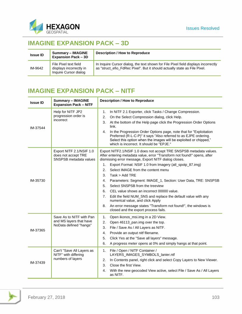
Issues Resolved
February 27, 2018 103
IMAGINE EXPANSION PACK – 3D
Issue ID Summary – IMAGINE Expansion Pack – 3D
Description / How to Reproduce
IM-9642 File Pixel text field displays incorrectly in Inquire Cursor dialog
In Inquire Cursor dialog, the text shown for File Pixel field displays incorrectly as "struct_efio_FdRec Pixel". But it should actually state as File Pixel.
IMAGINE EXPANSION PACK – NITF
Issue ID Summary – IMAGINE Expansion Pack – NITF
Description / How to Reproduce
IM-37544
Help for NITF JP2 progression order is incorrect
1. In NITF 2.1 Exporter, click Tasks / Change Compression.
2. On the Select Compression dialog, click Help.
3. At the bottom of the Help page click the Progression Order Options link.
4. In the Progression Order Options page, note that for "Exploitation Preferred (R-L-C-P)" it says "Also referred to as EJPE ordering. Select this option when the images will be exploited or chipped,” which is incorrect. It should be "EPJE."
IM-35730
Export NITF 2.1/NSIF 1.0 does not accept TRE SNSPSB metadata values
Export NITF2.1/NSIF 1.0 does not accept TRE SNSPSB metadata values. After entering metadata value, error "Transform not found!" opens, after dismissing error message, Export NITF dialog closes.
1. Export Format: NSIF 1.0 from Imagery (atl_spotp_87.img)
2. Select IMAGE from the content menu
3. Task > Add TRE
4. Parameters: Segment: IMAGE_1, Section: User Data, TRE: SNSPSB
5. Select SNSPSB from the treeview
6. CEL value shows an incorrect 00000 value.
7. Edit the field NUM_SNS and replace the default value with any numerical value, and click Apply
8. An error message states "Transform not found!", the windows is closed and the export process fails.
IM-37365
Save As to NITF with Pan and MS layers that have NoData defined "hangs"
1. Open ikonos_msi.img in a 2D View.
2. Open 46113_pan.img over the top.
3. File / Save As / All Layers as NITF.
4. Provide an output nitf filename.
5. Click Yes at the "Save all layers" message.
6. A progress meter opens at 0% and simply hangs at that point.
IM-37439
Can't "Save All Layers as NITF" with differing numbers of layers
1. File / Open / NITF Container / LAYERS_IMAGES_SYMBOLS_lanier.ntf
2. In Contents panel, right click and select Copy Layers to New Viewer.
3. Close the first View.
4. With the new geocoded View active, select File / Save As / All Layers as NITF.
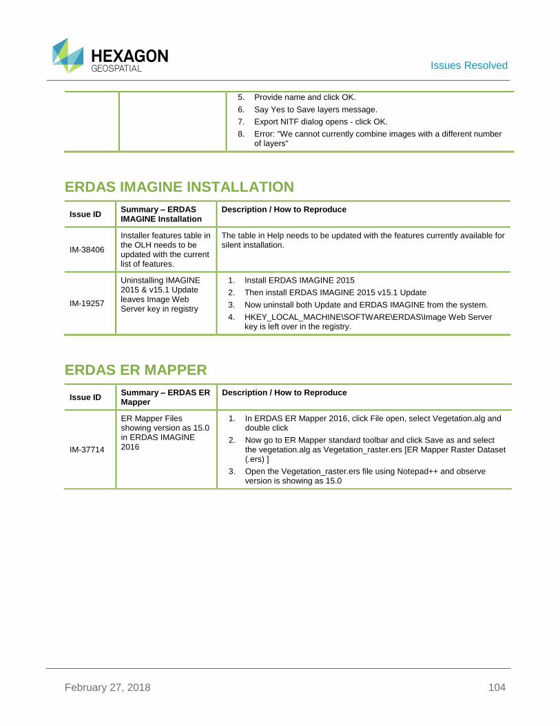
Issues Resolved
February 27, 2018 104
5. Provide name and click OK.
6. Say Yes to Save layers message.
7. Export NITF dialog opens - click OK.
8. Error: "We cannot currently combine images with a different number of layers"
ERDAS IMAGINE INSTALLATION
Issue ID Summary – ERDAS IMAGINE Installation
Description / How to Reproduce
IM-38406
Installer features table in the OLH needs to be updated with the current list of features.
The table in Help needs to be updated with the features currently available for silent installation.
IM-19257
Uninstalling IMAGINE 2015 & v15.1 Update leaves Image Web Server key in registry
1. Install ERDAS IMAGINE 2015
2. Then install ERDAS IMAGINE 2015 v15.1 Update
3. Now uninstall both Update and ERDAS IMAGINE from the system.
4. HKEY_LOCAL_MACHINE\SOFTWARE\ERDAS\Image Web Server key is left over in the registry.
ERDAS ER MAPPER
Issue ID Summary – ERDAS ER Mapper
Description / How to Reproduce
IM-37714
ER Mapper Files showing version as 15.0 in ERDAS IMAGINE 2016
1. In ERDAS ER Mapper 2016, click File open, select Vegetation.alg and double click
2. Now go to ER Mapper standard toolbar and click Save as and select the vegetation.alg as Vegetation_raster.ers [ER Mapper Raster Dataset (.ers) ]
3. Open the Vegetation_raster.ers file using Notepad++ and observe version is showing as 15.0

About Us
February 27, 2018 105
ABOUT US Hexagon Geospatial helps you make sense of the dynamically changing world. We enable you to envision, experience and communicate geographic information. Our technology provides you the form to design, develop and deliver solutions that solve complex, real-world challenges. Ultimately, this is realized through our creative software products and platforms.
CUSTOMERS. Globally, a wide variety of organizations rely on our products daily including local, state and national mapping agencies, transportation departments, defense organizations, engineering and utility companies, and businesses serving agriculture and natural resource needs. Our portfolio enables these organizations to holistically understand change and make clear, reliable decisions.
TECHNOLOGY. Our priority is to deliver products, platforms and solutions that make our customers successful. Hexagon Geospatial is focused on developing technology that displays and interprets information in a personalized, meaningful way. We enable you to transform location-based content into dynamic and useable business information that creatively conveys the answers you need.
PARTNERS. As an organization, we are partner-focused, working alongside our channel to ensure we succeed together. We provide the right platforms, products, and support to our business partners so that they may successfully deliver sophisticated solutions for their customers. We recognize that we greatly extend our reach and influence by cultivating channel partner relationships both inside and outside of Hexagon.
TEAM. As an employer, we recognize that the success of our business is the result of our highly motivated and collaborative staff. At Hexagon Geospatial, we celebrate a diverse set of people and talents, and we respect people for who they are and the wealth of knowledge they bring to the table. We retain talent by fostering individual development and ensuring frequent opportunities to learn and grow.
HEXAGON. Hexagon’s solutions integrate sensors, software, domain knowledge and customer workflows into intelligent information ecosystems that deliver actionable information. They are used in a broad range of vital industries.
Hexagon (Nasdaq Stockholm: HEXA B) has more than 18,000 employees in 50 countries and net sales of approximately 3.3bn USD. Learn more at hexagon.com and follow us @HexagonAB.

About Us
February 27, 2018 106
Copyright
© 2018 Hexagon AB and/or its subsidiaries and affiliates. All Rights Reserved. Hexagon has registered trademarks in many countries throughout the world. Visit the Trademarks Page for information about the countries in which the trademarks are registered. See Product Page and Acknowledgements for more information.
Product Documentation Terms of Use
PLEASE READ THESE TERMS CAREFULLY BEFORE USING HEXAGON GEOSPATIAL’S DOCUMENTATION ("DOCUMENT"). USE OF THIS DOCUMENT INDICATES ACCEPTANCE OF THIS AGREEMENT WITHOUT MODIFICATION. IF YOU DO NOT AGREE TO THE TERMS HEREOF ("TERMS"), DO NOT USE THIS DOCUMENT.
Use Of This Document
All materials in this Document are copyrighted and any unauthorized use may violate worldwide copyright, trademark, and other laws. Subject to the terms of this Agreement, Hexagon Geospatial (a Division of Intergraph Corporation) and Intergraph’s subsidiaries ("Intergraph") hereby authorize you to reproduce this Document solely for your personal, non-commercial use. In consideration of this authorization, you agree to retain all copyright and other proprietary notices contained therein. You may not modify the Materials in any way or reproduce or publicly display, perform, or distribute or otherwise use them for any public or commercial purpose, except as specifically authorized in a separate agreement with Hexagon Geospatial.
The foregoing authorization specifically excludes content or material bearing a copyright notice or attribution of rights of a third party. Except as expressly provided above, nothing contained herein shall be construed as conferring by implication, estoppel or otherwise any license or right under any copyright, patent or trademark of Hexagon Geospatial or Intergraph or any third party.
If you breach any of these Terms, your authorization to use this Document automatically terminates. Upon termination, you will immediately destroy any downloaded or printed Materials in your possession or control.
Disclaimers
ALL MATERIALS SUPPLIED HEREUNDER ARE PROVIDED "AS IS", WITHOUT WARRANTY OF ANY KIND, EITHER EXPRESSED OR IMPLIED, INCLUDING, BUT NOT LIMITED TO, ANY IMPLIED WARRANTIES OF MERCHANTABILITY, FITNESS FOR A PARTICULAR PURPOSE, OR NON-INFRINGEMENT. Hexagon Geospatial does not warrant that the content of this Document will be error-free, that defects will be corrected, or that any Hexagon Geospatial Website or the services that make Materials available are free of viruses or other harmful components.
Hexagon Geospatial does not warrant the accuracy and completeness of this Document. Hexagon Geospatial may make changes to this Document at any time without notice.
Limitation Of Liability
IN NO EVENT SHALL HEXAGON GEOSPATIAL BE LIABLE FOR ANY DIRECT, INDIRECT, INCIDENTAL, SPECIAL OR CONSEQUENTIAL DAMAGES, OR DAMAGES FOR LOSS OF PROFITS, REVENUE, DATA OR USE, INCURRED BY YOU OR ANY THIRD PARTY, WHETHER IN AN ACTION IN CONTRACT OR TORT, ARISING FROM YOUR ACCESS TO, OR USE OF, THIS DOCUMENT.
Indemnification
You agree to defend, indemnify, and hold harmless Hexagon Geospatial, its officers, directors, employees, and agents from and against any and all claims, liabilities, damages, losses or expense, including reasonable attorneys’ fees and costs, arising out of or in any way connected with your access to or use of this Document.
Use Of Software
Use of software described in this Document is subject to the terms of the end user license agreement that accompanies the software, if any. You may not download or install any software that is accompanied by or includes an end user license agreement unless you have read and accepted the terms of such license agreement. Any such software is the copyrighted work of Hexagon Geospatial, Intergraph or its licensors. Portions of the user interface copyright 2012-2018 Telerik AD.
Links To Third Party Websites
This Document may provide links to third party websites for your convenience and information. Third party websites will be governed by their own terms and conditions. Hexagon Geospatial does not endorse companies or products to which it links.

About Us
February 27, 2018 107
Third party websites are owned and operated by independent parties over which Hexagon Geospatial has no control. Hexagon Geospatial shall not have any liability resulting from your use of the third party website. Any link you make to or from the third party website will be at your own risk and any information you share with the third party website will be subject to the terms of the third party website, including those relating to confidentiality, data privacy, and security.
Trademarks
The trademarks, logos and service marks ("Marks") displayed in this Document are the property of Hexagon Geospatial, Intergraph or other third parties. Users are not permitted to use Marks without the prior written consent of Hexagon Geospatial, Intergraph or the third party that owns the Mark. "Intergraph" is a registered trademark of Intergraph Corporation in the United States and in other countries. Other brands and product names are trademarks of their respective owners.
Find additional trademark information.
Procedure For Making Claims Of Copyright Infringement
Notifications of claimed copyright infringement should be sent to Hexagon Geospatial by mail at the following address: Intergraph Corporation, Attn: Intergraph Legal Department, P.O. Box 240000, Huntsville, Alabama 35824.
US Government Restricted Right
Materials are provided with "RESTRICTED RIGHTS." Use, duplication, or disclosure of Materials by the U.S. Government is subject to restrictions as set forth in FAR 52.227-14 and DFARS 252.227-7013 et seq. or successor provisions thereto. Use of Materials by the Government constitutes acknowledgement of Hexagon Geospatial or Intergraph’s proprietary rights therein.
International Use
You may not use or export Materials in violation of U.S. export laws and regulations. Hexagon Geospatial makes no representation that Materials are appropriate or available for use in every country, and access to them from territories where their content is illegal is prohibited.
Hexagon Geospatial provides access to Hexagon Geospatial international data and, therefore, may contain references or cross references to Hexagon Geospatial products, programs and services that are not announced in your country. These references do not imply that Hexagon Geospatial intends to announce such products, programs or services in your country.
The Materials are subject to U.S. export control and economic sanctions laws and regulations and you agree to comply strictly with all such laws and regulations. In addition, you represent and warrant that you are not a national of, or otherwise located within, a country subject to U.S. economic sanctions (including without limitation Iran, Syria, Sudan, Cuba, and North Korea) and that you are not otherwise prohibited from receiving or accessing the Materials under U.S. export control and economic sanctions laws and regulations. Hexagon Geospatial makes no representation that the Materials are appropriate or available for use in every country, and access to them from territories where their content is illegal is prohibited. All rights to use the Materials are granted on condition that such rights are forfeited if you fail to comply with the terms of this agreement.
Revisions
Hexagon Geospatial reserves the right to revise these Terms at any time. You are responsible for regularly reviewing these Terms. Your continued use of this Document after the effective date of such changes constitutes your acceptance of and agreement to such changes.
Applicable Law
This Document is created and controlled by Hexagon Geospatial in the State of Alabama. As such, the laws of the State of Alabama will govern these Terms, without giving effect to any principles of conflicts of law. You hereby irrevocably and unconditionally consent to submit to the exclusive jurisdiction of the United States District Court for the Northern District of Alabama, Northeastern Division, or the Circuit Court for Madison County, Alabama for any litigation arising out of or relating to use of this Document (and agree not to commence any litigation relating thereto except in such courts), waive any objection to the laying of venue of any such litigation in such Courts and agree not to plead or claim in any such Courts that such litigation brought therein has been brought in an inconvenient forum. Some jurisdictions do not allow the exclusions or limitations set forth in these Terms. Such exclusions or limitations shall apply in all jurisdictions to the maximum extent allowed by applicable law.
Questions
Contact us with any questions regarding these Terms.