RELEASE 516 - Maintenance
259
EXPERION PKS RELEASE 516 EthernetIP User Guide EPDOC-X399-en-516A August 2020
Transcript of RELEASE 516 - Maintenance

EXPERION PKSRELEASE 516
EthernetIP User GuideEPDOC-X399-en-516A
August 2020

DisclaimerThis document contains Honeywell proprietary information. Information contained herein is to beused solely for the purpose submitted, and no part of this document or its contents shall bereproduced, published, or disclosed to a third party without the express permission of HoneywellInternational Sàrl.
While this information is presented in good faith and believed to be accurate, Honeywell disclaimsthe implied warranties of merchantability and fitness for a purpose and makes no expresswarranties except as may be stated in its written agreement with and for its customer.
In no event is Honeywell liable to anyone for any direct, special, or consequential damages. Theinformation and specifications in this document are subject to change without notice.
Copyright 2020 - Honeywell International Sàrl
- 2 -

Contents 3
Chapter 1 - About this guide 11.1 Revision history 1
1.2 Terms and Definitions 1
Chapter 2 - Introduction 72.1 Overview 7
2.1.1 The Common Industrial Protocol (CIP™) 7
2.1.2 Ethernet/IP™ 7
2.1.3 Interoperability 8
2.1.4 Essential CIP Concepts and Terms 8
Chapter 3 - Experion EIP Solutions Overview 123.1 Summary of Experion EIP Solutions 12
3.2 EtherNet/IP Topologies Supported 14
3.3 Major Classification of EtherNet I/P Devices 16
3.4 Common EIP I/O Device Structures 16
3.4.1 Generic I/O Devices: 17
3.4.2 Modular I/O Devices: 17
3.4.3 DeviceNet Devices: 18
3.5 EIP Device Types and Interface Methods 18
3.6 Solution Configuration in Control Builder 20
3.7 Ethernet/IP Device Templates Present in Experion Library 20
Chapter 4 - EIP Network Details 234.1 C300 Direct EIP Solution 23
4.1.1 Prerequisites 23
4.1.2 C300 DIRECT Solution - FTE Topology 24
4.1.3 Assigning EIP to the C300 25
4.1.4 C300 Direct Solution - Rules and Caveats 26
4.1.5 C300 Direct Solution – Sample EIP Topologies 28
4.2 C300 EIM EIP Solution 29
4.2.1 Prerequisites 29
4.2.2 Assigning EIP Capability to the C300 29
Chapter 5 - EIM Block Configuration 315.1 EIM Redundancy Option 34
5.2 C300 EIM FTE Topologies and Overview 35
- 3 -

5.3 C300 EIM Solution - Rules and Caveats 36
5.3.1 EIM EIP Solution – Sample Topologies Using Stratix 8000 38
5.3.2 EIM EIP Solution – Sample DLR Using 1783-ETAPs 39
5.3.3 EIM EIP Solution – Sample DLR Using the Stratix 5700 40
Chapter 6 - Creating Ethernet/IP™ Device, Drive, and I/O Module Types 416.1 Prerequisites 41
6.2 Creating Ethernet/IP™ device types using EDS files 41
6.4 Creating Ethernet/IP™ drive types using EDS files 42
6.4.1 To create device types using EDS files 42
6.5 Creating Ethernet/IP™ drive types without EDS files 50
6.6 Creating Ethernet/IP™ I/O module types using EDS files 53
6.7 Creating Ethernet/IP™ I/O module types without EDS files 56
6.8 Configuring data link parameters 58
Chapter 7 - Introduction to UDT Concepts 617.1 What is a ControlLogix UDT and How is it Used? 61
7.2 UDT – Input Parameters & Output Parameters 62
7.3 UDT - Data Types Supported in Experion R511 62
7.4 UDT Template vs. Instance Concept 64
7.5 CPU Loading Due to UDT Points 64
7.6 C300 and ControlLogix integration 65
7.7 Configuring ControlLogix Tags in peer references fromExperion strategies 66
7.7.3 Configuring the ControlLogix Gateway block 70
7.7.4 Creating Control Logix Aggregate UDT Type 71
7.7.5 Creating Control Logix Scalar UDT Type 74
7.7.6 Defining the ControlLogix tag access 88
7.7.7 Using Aggregate or Scalar Tag Instance for Read and Write Operations 91
Chapter 8 - Planning and Design 938.1 Planning EtherNet/IP implementation 93
8.1.1 Network requirements 93
8.1.2 Ethernet/IP™ implementation architecture and topology 97
Chapter 9 - Ethernet/IP™ Device Configuration in CEE 1079.1 Guidelines for Ethernet/IP™ device configuration 108
9.2 Known limitations 111
- 4 -

9.3 Configuring the ArmorPoint Ethernet/IP™ adapter block 115
9.3.5 Consolidate connections 116
9.3.6 Configuring the IP address of an Ethernet/IP™ device 117
9.4 Configuring ArmorPoint I/O module blocks 118
9.5 Configuring ArmorBlock I/O module blocks 119
9.6 Configuring the EIP GenAdapter Block 121
9.7 Configuring the IP address of an EIP device 128
9.8 Configuring GenAdapter I/O module blocks 128
9.9 Slot 0 Diagnostic Information 130
9.10 Slot 0 Configuration 131
9.11 Configuring PowerFlex drive blocks 132
9.12 Configuring E3 relay blocks 133
9.13 Assigning Ethernet/IP™ devices to the CEE C300 block 135
9.14 Configuring channels in Ethernet/IP™ devices 136
9.15 Ethernet/IP™ device configuration references 136
9.15.1 Advance Configuration or Statistics 137
9.15.2 Alarms tab 138
9.15.3 Channel Configuration tab 138
9.15.4 Configuration tab 142
9.15.5 Data/Status tab and Data/Command tab in PowerFlex drive block 142
9.15.6 Data/Status tab and Data/Command tab in E3/E3 plus relay blocks 145
9.15.7 Sensor Type and PV Low and High Signal range for RTD module - ArmorBlock 1732E-IR4IM12R 149
9.15.8 Sensor Type and PV Low and High Signal range for Thermocouple module -Armor Block 1732E-IT4IM12R 150
9.15.9 Cold junction configuration for thermocouple module - Armor Block 1732E-IT4IM12R 151
9.15.10 Digital Filter configuration for thermocouple and RTD modules of theArmor block family 154
9.15.11 PV scaling factor configuration in thermocouple modules 154
9.16 Through EIM Ethernet/IP™ Different Topology ExampleScenarios 155
9.16.1 EIM primary and secondary downlinks are connected to single switch 155
9.16.2 EIM primary and secondary downlinks are connected to different switches 156
9.16.3 EIM primary and secondary downlinks are directly connected to DLR 156
9.16.4 Multiple EIMs are sharing same device network through switch 157
9.16.5 Multiple EIMs are sharing same device network through DLR 158
- 5 -

9.16.6 ControlLogix SCADA access 158
9.17 On Demand Connect Feature for EIP blocks 159
9.17.1 Connect On-Demand 159
9.17.2 User Scenarios 161
9.17.3 Scenarios specific to Non-Chassis, Adapter/Chassis with Direct connectionsand Adapter Modules 163
9.17.4 Scenarios specific to Adapter based Modules 167
9.17.5 Scenarios specific to Adapter based Modules, being used withoutconsolidation of connections 168
9.17.6 Scenarios specific to Adapter based Modules, being used with consolidationof connections 169
Chapter 10 - Configuring ControlNet IOMs in Ethernet/IP™ 17310.1 UOC vUOC supported topologies with ControlNet IOMs 173
10.1.1 Non-Redundant Star IO Network with UOC 173
10.1.2 DLR IO Network with UOC 174
10.2 Cascaded network support in UOC to ControlNet IOModules 175
10.2.1 Cascaded network support in ControlNet IOMs 176
10.2.2 Cascaded network support with Redundant Chassis 176
10.2.3 Ethernet IP Network with ControlNet IOMs 177
10.2.4 Non-Redundant Star IO Network with vUOC 178
10.2.5 Design for Cascaded network support 179
10.3 Configuring ControlNet IO 179
10.4 ControlNet Alarms 184
Chapter 11 - Ethernet/IP™ Supportability 18511.1 Ethernet/IP™ device configuration 186
11.2 Parameter Definition Editor (PDE) Grid Tabs 187
11.3 Device type modification 190
11.3.3 Modifying device types 191
Chapter 12 - EIP IO behavior during C300 or EIM switchover 194
Chapter 13 - Simulate Control Strategy 19513.1 For UDT Blocks 195
13.2 For IO Blocks 195
Chapter 14 - Troubleshooting Scenarios (Hardware and Software) 196
Chapter 15 - CIP Error code 19715.1 Status Codes 197
- 6 -

15.2 Connection Manager Service Error Codes 202
15.3 Honeywell specific Extended error code 230
Chapter 16 - Appendix - A 23116.1 Third Party EIP Network Component Details 231
16.2 Configuring a Stratix switch for Ethernet/IP™ integration 231
16.2.1 Prerequisites 231
16.2.2 To configure the Stratix switch for Ethernet/IP™ integration 231
16.2.3 Connecting locally to the switch 232
16.2.4 Checking the version of the switch IOS 232
16.2.5 Accessing switch configuration files 233
16.2.6 Configuring switch interface options 237
16.2.7 Loading the switch configuration file 240
16.2.8 Switch Maintenance 241
16.3 Tofino firewall configuration 242
16.3.1 Software and hardware requirements for Tofino firewall configuration 243
16.3.2 Configuring the Tofino firewall 244
- 7 -

ABOUT THIS GUIDE
This document provides an overview and implementation details related to the Experion C300 andUOC controller integration with Ethernet/IP™ networks and Ethernet/IP conformant devices.
The following EtherNet/IP solutions are covered in this guide:
l C300 Direct solution: First released with Experion R430
l C300 EIM (Ethernet Interface Module) solution: First released with Experion R500
l UOC Downlink solution: First released with Experion R505
NOTE
The Experion SCADA EtherNet/IP solution is covered in a separate document.
1.1 Revision history
Revision Date Description
A August 2020 Initial release of the document
1.2 Terms and Definitions
Term Definition
EtherNet/IPDevice
A CIP protocol concept. An Adapter device (or I/O Adapter) isa device on the EtherNet/IP network that connects to theprocess and performs some process related function. Someexamples include I/O subsystems (typical AI, AO, DI, and DOI/O modules), field instruments (like valves and transmitters),Variable Frequency Drive controllers, motor starters, and thelike. Scanner devices connect to adapter devices to transfer(read and write) data. Relative to this document, the C300,UOC and EIM are considered a scanner device.
Adapter Block A Control Builder concept. A function block configured inControl Builder to represent the Adapter Module of a modularIO station such as Rockwell AB’s Armor Point IO.
- 1 -
CHAPTER
1

Term Definition
AdapterModule
A communication device which connects to the Ethernet/IP™network to serve data from a set of devices or modulesunderneath it. Adapter Modules typically support IOconnectivity from Scanners via implicit Ethernet/IP™connections.
Assembly A CIP protocol concept. Provides the mechanism to pass databetween the Scanner and Adapter device over theEtherNet/IP network.
An assembly is a pre-defined set of data (parameters) residingin an Adapter device. Each assembly can consist of multipleparameters that can be of different data types. Assemblies areidentified by a unique instance number and are usuallydefined by the Adapter vendor.
Three types of assemblies are:
l Input (data to be sent from adapter to scanner)
l Output (data to be sent from scanner to adapter), and
l Configuration (a data area reserved for information abouthow consumed and produced data is to be interpreted).
The user entered RPI setting determines the update rate forthe input and output assemblies. Input and output assembliesutilize Implicit messaging.
CIP Common Industrial Protocol (CIP™). CIP is the protocollanguage used to enable communication between all nodeson the network. CIP is physical media and data link layerindependent. This media independence provides the ability tochoose the CIP Network best suited for your application. CIPvariants include ControlNet, CompoNet, DeviceNet, andEthernet/IP. CIP and all of its variants are managed andcontrolled by ODVA. More information can be found at thefoundation website. WWW.ODVA.org
ControlLogixUDT Tag
A unique Tag name is assigned to each UDT. UDTs are used totransfer data between the ControlLogix PLC and theC300/UOC. See UDT definition below.
A named data item resident in a Rockwell AB ControLogixPLC. Individual, scalar data items can be named with Tags orgroups of data called structures can be named with Tags. Thetransport of tagged data between Honeywell Controllers/EIMand ControlLogix is accomplished using User Defined DataType (UDT) Blocks.
- 2 -
Chapter 1 - About this guide
Chapter 1 - About this guide
Term Definition
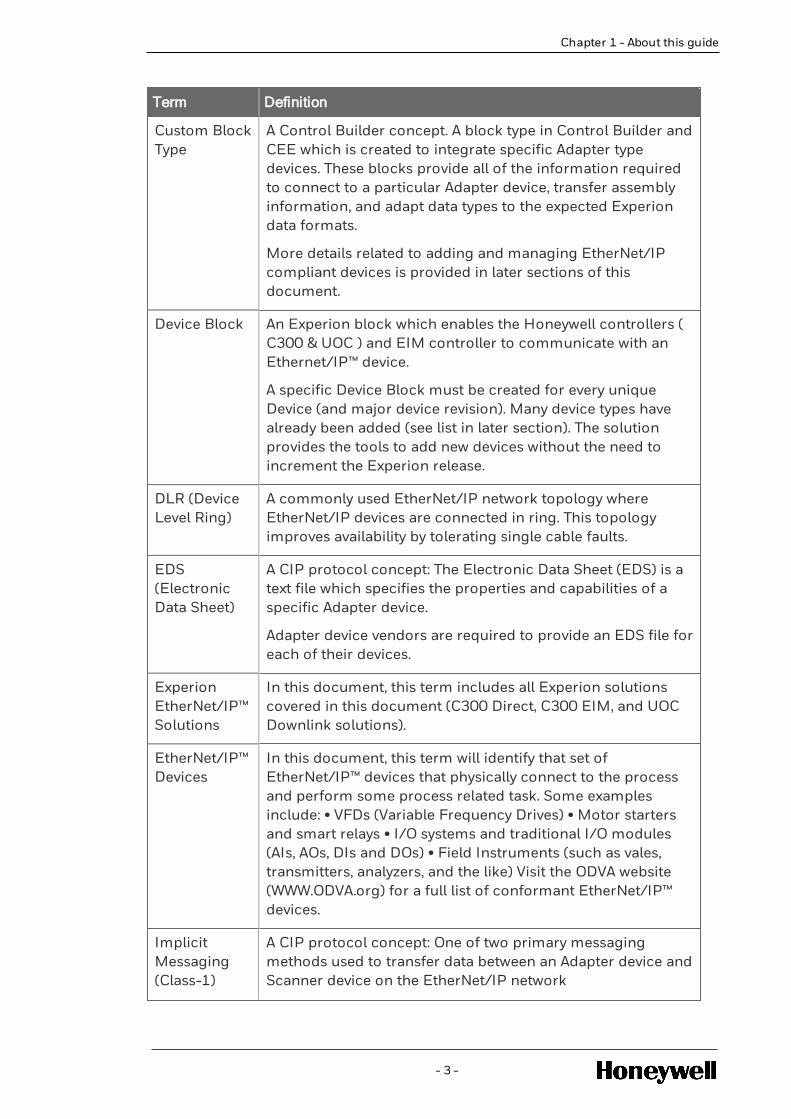
Custom BlockType
A Control Builder concept. A block type in Control Builder andCEE which is created to integrate specific Adapter typedevices. These blocks provide all of the information requiredto connect to a particular Adapter device, transfer assemblyinformation, and adapt data types to the expected Experiondata formats.
More details related to adding and managing EtherNet/IPcompliant devices is provided in later sections of thisdocument.
Device Block An Experion block which enables the Honeywell controllers ( C300 & UOC ) and EIM controller to communicate with anEthernet/IP™ device.
A specific Device Block must be created for every uniqueDevice (and major device revision). Many device types havealready been added (see list in later section). The solutionprovides the tools to add new devices without the need toincrement the Experion release.
DLR (DeviceLevel Ring)
A commonly used EtherNet/IP network topology whereEtherNet/IP devices are connected in ring. This topologyimproves availability by tolerating single cable faults.
EDS(ElectronicData Sheet)
A CIP protocol concept: The Electronic Data Sheet (EDS) is atext file which specifies the properties and capabilities of aspecific Adapter device.
Adapter device vendors are required to provide an EDS file foreach of their devices.
ExperionEtherNet/IP™Solutions
In this document, this term includes all Experion solutionscovered in this document (C300 Direct, C300 EIM, and UOCDownlink solutions).
EtherNet/IP™Devices
In this document, this term will identify that set ofEtherNet/IP™ devices that physically connect to the processand perform some process related task. Some examplesinclude: • VFDs (Variable Frequency Drives) • Motor startersand smart relays • I/O systems and traditional I/O modules(AIs, AOs, DIs and DOs) • Field Instruments (such as vales,transmitters, analyzers, and the like) Visit the ODVA website(WWW.ODVA.org) for a full list of conformant EtherNet/IP™devices.
ImplicitMessaging(Class-1)
A CIP protocol concept: One of two primary messagingmethods used to transfer data between an Adapter device andScanner device on the EtherNet/IP network
- 3 -

Term Definition
Implicit messaging is well suited for data that must betransferred in a cyclic manner. This data transfer mechanismis fast, deterministic, and well suited for data that is used fordirect control and logic applications. Data transfer with allEtherNet/IP™ I/O Devices uses Implicit messaging.
ExplicitMessaging(Class-3)
A CIP protocol concept: One of two primary messagingmethods used to transfer data between an Adapter device andScanner device on the EtherNet/IP network.
Explicit messaging is used to transfer non-time criticalinformation (like device configuration parameters). It is wellsuited for data that does not need to be cyclic andapplications that can tolerate a lower level of determinism.
UDTs use Explicit messaging to transfer data betweenControlLogix and C300/UOC controllers.
InputAssembly
A CIP protocol concept. Provides the mechanism to pass databetween the Scanner and Adapter device over theEtherNet/IP network.
An assembly is a pre-defined set of data (parameters) residingin an Adapter device. Each assembly can consist of multipleparameters that can be of different data types. Assemblies areidentified by a unique instance number and are usuallydefined by the Adapter vendor.
In this manual, Input Assemblies are used to transfer datafrom EIP I/O Devices to the C300/EIM and UOC. The RPIsetting determines the update rate.
OutputAssembly
A CIP protocol concept. Provides the mechanism to pass databetween the Scanner and Adapter device over theEtherNet/IP network.
An assembly is a pre-defined set of data (parameters) residingin an Adapter device. Each assembly can consist of multipleparameters that can be of different data types. Assemblies areidentified by a unique instance number and are usuallydefined by the Adapter vendor.
In this manual, Output Assemblies are used to transfer datafrom C300/EIM and UOC to EtherNet/IP™ I/O Devices. TheRPI setting determines the update rate.
ConfigurationAssembly
A CIP protocol concept. An Assembly which transportsconfiguration data from the Scanner to the Adapter device.
Configuration Assemblies are sent at the time that a
- 4 -
Chapter 1 - About this guide

Chapter 1 - About this guide
Term Definition
connection is initially established with the Adapter device.
A Configuration Assembly byte size of zero is sent when theConfiguration Assembly is not supported for the givenAdapter device. In this case, configuration must be providedby a separate Ethernet/IP™-connected tool.
IO ModuleBlock
A Control Builder and CEE tagged block is used to interfacewith traditional AI, AO, DI, and DO modules and channels.Each of the I/O modules may have their own dedicated EIPinterface (also referred to as block I/O), or may have amodular I/O architecture where a single EtherNet/IP™interface is shared by a number of assigned I/O modules. Achassis I/O solution is one example of a Modular I/O solution.
Modular IO A modular IO is a typical chassis with adapter module and aset of Input Output Modules (IOMs). The adaptor moduleprovides the interface to the chassis for Input OutputModules (IOMs). One IP address is required to communicatewith the chassis. One Implicit connection may be required foreach IOM.
The Adopter consolidates IOM data and sends data toscanner. Scanner in turn parses the data.
PDE(ParameterDefinitionEditor)
Control Builder Tool: The Parameter Definition Editor (PDE)tool is invoked within Control Builder.
With respect to the Honeywell EtherNet/IP™ solutions, thetool is used for the following:
• To complete EtherNet/IP™ I/O Device configurationconfiguration and information that was not contained in thevendor EDS file.
• To complete parameter entries for UDT points
RPI(RequestedPacketInterval)
Requested Packet Interval: A user entered value (inmilliseconds). It determines the update rate for the following:
l Input Assemblies via Implicit messaging
l Output Assemblies via Implicit messaging
l UDT data transfer between the C300 and ControlLogixPLC via Explicit messaging
Note: Always check vendor device specifications forsupported range of RPI settings.
Scanner A CIP protocol concept. Scanner devices connect to the
- 5 -

Term Definition
Device Ethernet/IP™ network and communicate with Adapter typedevices. See Adapter device definition.
Relative to this document, the C300, EIM, and UOC areconsidered to be Scanner devices. They can directly connectto Adapter devices to read and write data that can be used forcontrol, logic, and to provide information for the operatorinterface.
UDT (UserDefined DataType)
A Rockwell PLC term and concept: User Defined-Data Type.(UDT) is a mechanism for transferring data (as reads andwrites) between the C300 and a ControlLogix PLC.
In concept the user creates UDTs on the ControlLogix sidethat consist of a set of user defined parameters of userdefined data types. The UDT is then assigned a unique Tagname. The user then creates an identical UDT (and Tagreference) in Control Builder and downloads the UDT to theC300.
Data transfer (as inputs and outputs) then commence andcontinue according to the user entered RPI setting. Explicitmessaging is used for UDT points.
UDT types supported: (UDTs are fully defined by the user)
l Multi-Parameter or Aggregate: Can have multipleparameters of different data types.
l Scalar: Has one parameter of a given data type
UDT Block A Control Builder concept: A block created in Control Builder.The user creates a UDT block on the Experion side thatexactly matches a UDT that has been created on theControlLogix side.
In concept, the user will create a UDT template on theControlLogix side. They must then create an identical UDTtemplate on the Control Builder side. Each UDT Blockrepresents one of these UDT templates. One UDT Block isrequired for every different UDT template. Instances of thetemplate can then be created and assigned unique TagNames. The Tag Names must match on the ControlLogix andC300/EIM/UOC side.
See UDT definition for more details.
IO Modules The input/output module (I/O module) is normally connectedto the computer system on one end and one or moreinput/output devices on the other.
UOC Unit Operations Controller
- 6 -
Chapter 1 - About this guide

INTRODUCTION
2.1 Overview
2.1.1 The Common Industrial Protocol (CIP™)
EtherNet/IP™ DeviceNet™, ControlNet™, and CompoNet™, are commonly used industrial networksolutions. These network solutions are all linked by one common protocol, the Common IndustrialProtocol (CIP™).
It’s important to separate CIP (the communication protocol) from the network infrastructureselected to transport the digital packets from node to node.
CIP is a media independent protocol and is currently implemented on the following networks…
l CompoNet™ …………. CIP on TDMA technology
l ControlNet™ ………… CIP on CTDMA technology
l DeviceNet™ …………. CIP on CAN technology
l EtherNet/IP™…....... CIP on ETHERNET technology
EtherNet/IP is the primary focus of this document.
CIP encompasses a comprehensive suite of messages and services to fully support a broadspectrum of applications including control, safety, energy, synchronization & motion, informationand network management. CIP is applicable to both process and factory automation in bothcontinues and batch operations.
CIP is a modern, mature, and object oriented protocol that provides connections betweenindustrial devices (sensors, actuators, drives, motors, I/O, etc.) and higher-level devices(controllers and user interfaces). CIP is the protocol language used to enable communicationbetween all nodes on the network. It is physical media and data link layer independent. This mediaindependence provides the ability to choose the CIP Network best suited for your application.
CIP and the network variants above are promoted, controlled, and managed by ODVA. Refer to theODVA website for more information and a list of ODVA conformant CIP devices and vendors.
WWW.ODVA.org
2.1.2 Ethernet/IP™
In the simplest terms, Ethernet/IP™ is CIP as implemented over standard Ethernet. This enablesthe user to realize all of the benefits of both CIP and the Ethernet technology (IEEE 802.3combined with the TCP/IP Suite).
Ethernet/IP networks can host a variety of different I/O devices (such as Variable FrequencyDrive controllers, motor starters, typical I/O modules, field instruments, to name a few) from alarge list of vendors. The user can satisfy a broad spectrum of process control needs over onenetwork and using one protocol.
Additional EtherNet/IP details and a full list of conformant EtherNet/IP devices can be found onthe ODVA website.
- 7 -
CHAPTER
2

The Experion EIP solutions provide a comprehensive and effective integration to EtherNet/IPnetworks and conformant EtherNet/IP I/O devices. These smart networked I/O devices along withthe large amount of valuable process and device data resident in each, can be used to……..
l Augment control and logic
l Augment plant operations
l Improve maintenance
l Simplify engineering, and
l Extend asset life cycles
2.1.3 Interoperability
To become an ODVA conformant device, all EIP devices must comply with all CIP and EtherNet/IPspecifications and mandatory behaviors.
Strict adherence to specifications and device conformance testing ensures interoperabilitybetween all devices connected on the EtherNet/IP network. This enables multiple devices, ofdifferent types and from different vendors, to interoperate on the same network without issues. Italso allows host systems, like Experion, to seamlessly interface with any conformant device toeffectively monitor and control the process.
Visit the ODVA website for more details on ODVA conformance requirements and device testing.
The Experion EIP solutions provide tools in Control Builder that allows for the addition of newconformant EIP devices without the need to increment the Experion release.
All three solutions (C300 direct, C300 EIM, and UOC Downlink) use the same tool set andprocedures to add a new EIP device. A device that has been added for one solution will work withthe other two.
ATTENTION
At this time, only Honeywell personnel can perform the task of adding new EIP devices.Please contact your Honeywell representative for an up to date list of supported devices orto request the addition of a new device.
2.1.4 Essential CIP Concepts and Terms
This section will provide some key CIP and EIP concepts and terms. This information will be veryhelpful to your understanding of the Experion EIP solutions and the sections that follow.
Message Types
The CIP protocol provides for two major messaging methods, as follows:
1. Implicit Messaging
This messaging type is used for cyclic data transfer. It is designed to be fast and deterministic. Thisdata transfer mechanism is well suited for data that is used for primary control and logicapplications.
Implicit messaging uses Producer/Consumer transactions.
2. Explicit Messaging
- 8 -
Chapter 2 - Introduction

Chapter 2 - Introduction
This messaging type is used for acyclic data transfer. It is used to transfer non-time criticalinformation. One example would be parameter reads/writes related to device configuration. It iswell suited for data that does not need to be cyclic and applications that can tolerate some variationin determinism.
Explicit messaging uses Request/Reply transactions.
Input and Output Assemblies
Input and Output Assemblies are used as the data transfer mechanism for Implicit data transfersbetween EIP I/O devices and the Experion EIP solutions.
Assembly Concepts: Refer to figure Input and Output Assembly Concept.
l All EIP I/O devices have a large amount of process and device data (parameters) resident intheir memory.
l An assembly is a pre-defined set of data (parameters of a given data type) selected from thetotal parameters available in the I/O device.
l Assemblies are defined by the I/O device vendor. The device vendor determines what deviceparameters will be assigned to a given assembly.
l The device vendor assigns a unique identification number to each assembly. This uniqueinstance number is used to identify the assembly to be transferred in each Implicit transaction.
l Depending on the device type and its function, it may have an Input Assembly or OutputAssembly or both.
NOTE
You can usually do a search in the vendor document for the terms Input Assembly or OutputAssembly to determine available assemblies, assigned parameters, assembly structure, andtheir assigned instance numbers.
Input and Output Assemblies are utilized by Implicit data messaging as follows:
Refer to figure Input and Output Assembly Concept.
Input Assemblies
The following are the Implicit messaging steps:
1. Experion EIP Solution connects to the EIP I/O device.
2. Experion EIP Solution indicates the assembly instance (by number) to be transferred.
Also indicates the update rate per the user entered RPI setting in milli-seconds.
3. Data Flow: EIP I/O device then continuously transmits the entire Input Assembly (allparameters) to the C300, EIM, or UOC in one packet. This cyclic transaction continues (per theRPI) until the connection is either lost or terminated.
Output Assemblies
The following are the Implicit messaging steps:
1. Experion EIP solution connects to the EIP I/O device.
2. Experion EIP solution indicates the assembly instance (by number) to be transferred.
Also indicates the update rate per the user entered RPI setting in milli-seconds.
- 9 -

3. Data Flow: The Experion EIP Solution then continuously transmits the entire Output Assembly(all parameters) to the EIP I/O Device in one packet. This cyclic transaction continues (per theRPI) until the connection is either lost or terminated.
Input and Output Assemblies enable the Experion EIP Solutions to monitor and control theprocess through the associated EIP I/O Device. Implicit data transfer is fast and deterministic.
Requested Packet Interval (RPI)
Requested Packet Interval is a user entered value (in milli-seconds) that sets the update rate fordata transmission for Input Assemblies, Output Assemblies, and UDTs.
NOTE
The RPI range is determined by the vender and Experion will support range from 50ms to2sec in multiple of 50. user can use the vender supported range which is falling in Experionrange.
Figure 2.1 Input and Output Assembly Concept
Configuration Assembly
An Assembly which transports configuration data from the C300, EIM, or UOC to the EIP I/Odevice. Configuration Assemblies are sent at the time that a connection is initially established. AConfiguration Assembly byte size of zero indicates that this assembly is not supported.
Electronic Data Sheet (EDS)
The Electronic Data Sheet (EDS) is a text file which specifies the properties and capabilities of aspecific EIP I/O Device. ODVA mandates that the vendor must provide an EDS file for every device(and major device revision). EDS files are used by the Experion EIP Solutions to add new devices.
- 10 -
Chapter 2 - Introduction

Chapter 2 - Introduction
NOTEAlthough the EDS file can contain all information needed to create a full I/O Device Block(connection, input assembly, output assembly, and configuration assembly information),ODVA only mandates that an EDS file provide device ID information. The solution providesthe PDE tool to allow the user to manually enter any data that is missing in the EDS file. Youshould always check with your selected device vendor to determine if they provide acomplete EDS file. When using the PDE tool you will need access to detailed vendordocumentation that describes all information required to create the device I/O Block.
- 11 -

EXPERION EIP SOLUTIONS OVERVIEW
NOTE
Any references in this document to specifications or limits are provided for concept only.Always consult the appropriate specifications document for any project planning.
3.1 Summary of Experion EIP Solutions
It is important to distinguish between the various Experion EIP Solutions. The table belowprovides a high level description and some distinguishing characteristics for each.
ExperionSolutionName(Note-1)
FirstReleasedwithExperion
High level Solution Description
C300DIRECTEIPSolution
R430 Refer to Figure-3.1. This solution can be characterized by the way theC300 control processor is interfaced with the EtherNet/IP network andEIP devices. As shown, The C300 communicates over FTE Level-2,through a Tofino firewall, to the EIP network and devices. The Tofinofirewall provides protection between the FTE and EtherNet/IP networkand devices. Only the C300 can be redundant. The FTE cable and Tofinocannot be redundant. This solution can be implemented on C300 modelCC-PCNT01 or CC-PCNT02. Although this solution is still supported, theC300 EIM solution is preferred and has enhanced functionality andimproved specifications and limits. Use of this solution will reduce themax limit of FTE nodes from 330 to 200.
C300EIM EIPSolution
R500 Refer to Figure-3.2. This solution can be characterized by the way theC300 control processor is interfaced with the EtherNet/IP network andEIP devices. As shown, The C300 communicates over FTE Level-2,through the Ethernet Interface Module (EIM), to the EIP network anddevices. The EIM is a new module in the Series C form factor that wasfirst released with Experion R500. The EIM provides both the FTE firewall(embedded CF9-like functions) and the EIP firewall function. This solutioncan be implemented on C300 model CC-PCNT02 only. The EIM solutionprovides optional redundancy from the C300, through the EIM, to a DLREIP network. The EIM can be implemented at FTE Level-1 or Level-2.
UOCDownlinkEIPSolution
R505 Refer to Figure-3.3. This solution can be characterized by the way theUOC (Unit Operations Controller) is interfaced with the EtherNet/IPnetwork and EIP devices. As shown, The UOC has EtherNet/IP downlinksdirectly on the UOC processor. Refer to the UOC Users Guide for moredetails and EIP network topologies.
SCADAEIP
Note-2 Note-2
- 12 -
CHAPTER
3

ExperionSolutionName(Note-1)
FirstReleasedwithExperion
High level Solution Description
Solution
Note-1: All of these solutions can be used simultaneously on the same ServerCluster. However, the specification limits of one solution can affect the limitsof the others. Always consult the appropriate specification documents.
Note-2: The SCADA solution is covered in a separate document. No furtherSCADA coverage is provided in this document.
Figure 3.1 C300 Direct EIP Solution
Figure 3.2 C300 EIM Solution
Figure 3.3 UOC EIM Solution
- 13 -
Chapter 3 - Experion EIP Solutions Overview

Chapter 3 - Experion EIP Solutions Overview
3.2 EtherNet/IP Topologies Supported
This section will provide a high-level overview of the three EtherNet/IP network topologies. Thetopologies can be implement individually or in any combination of the three.
The tree topologies are as follows:
l Liner Bus
l Star
l DLR (Device level Ring)
DLR (Device Level Ring): The DLR is a very popular topology. It provides an added level ofrobustness and availability. The DLR can tolerate single cable faults. Devices may have an EIPinterface that can natively support and participate in the DLR. Native DLR devices have two EIPcable connectors and fully understand how to connect and participate in the ring. Non-nativedevices are connected to the ring using the Rockwell 1783 ETAP module.
Basic Topology Diagrams
Figure 3.4 Linear Bus
Figure 3.5 Linear Bus
- 14 -

Figure 3.6 DLR Topology
The table below summarizes the topologies supported by EIP solution and identifies the qualifiedhardware for each.
EIP Network Topologies Supported EIP Network Hardware Supported
SolutionLinearBus
Star DLRStratix8000
Stratix5700
Rockwell1783ETAP
TofinoXenonFirewall
C300Direct(1)
Yes Yes Yes (3) Yes No Yes Yes
C300 EIMSolution(1)
Yes Yes Yes (3) Yes Yes Yes N\A
UOCDownlink(2)
Yes Yes Yes Yes Yes Yes N\A
Note-1: Additional networking details are provided later in the document.
Note-2: For networking details for this solution, refer to the UOC User’s Guide.
Note-3: For DLR - C300 Direct and C300 EIM, Rockwell 1783 ETAP must beconnected to enable DLR topology. For UOC, Embedded DLR is supported inController and no ETAP is required.
- 15 -
Chapter 3 - Experion EIP Solutions Overview

Chapter 3 - Experion EIP Solutions Overview
3.3 Major Classification of EtherNet I/P Devices
The manner in which control strategies are configured in the C300 for Ethernet/IP™ connectionwith respect to this document and the Honeywell EIP solutions (C300-Direct, C300-EIM, and UOC-Downlink), all EIP network connected devices can be placed into two major categories, as follows:
1. EIP Devices: This includes a category of devices that directly connect to the process andperform some type of process related function.
Some devices that fall into this category include:
l Variable Frequency Drives (VFDs),
l Motor starters and smart relays,
l Typical I/O modules (AI, AO, DI, DO and PI),
l Field instruments (such as valves, transmitters, analyzers, etc.),
l See ODVA website for a complete listing of conformant devices.
The C300 and UOC can connect to and read/write data with these devices to perform primarycontrol and logic.
CIP Implicit messaging is used to ensure that the data transfer is fast and deterministic.
A device-specific EIP I/O Block must be created in Control Builder for every different device typeand major device revision.
EIP I/O Blocks utilize the CIP concept of Input Assemblies, Output Assemblies, and ConfigurationAssemblies.
Update rates are determined by the user entered RPI setting in milli-seconds.
Solution tools provided in Control Builder to create device-specific EIP I/O Blocks:
l EDS parser tool: Processes the EDS file to create the initial I/O Block.
l PDE tool: Allows the user to modify the I/O Block.
2. PLCs: Currently this category only includes the Rockwell ControlLogix PLC. User created UDTsare used to identify and transfer the desired data between the C300/UOC and theControlLogix PLC.
UDTs are used to establish a supervisory control relationship between the C300/UOC and theControlLogix PLC. In this relationship the C300/UOC is considered the supervisor and the PLC isconsidered to be the primary controller.
UDTs can be of type Multi-parameter (Aggregate) or Single-parameter (Scalar).
UDTs are fully defined by the user (Structure, naming, number of parameters, and assignment ofdata types).
UDTs (Class 3) use CIP Explicit messaging.
Update rates are determined by the user entered RPI setting in milli-seconds.
Solution tools provided in Control Builder to create UDTs:
l PDE tool: Allows the user to create the UDT Template.
3.4 Common EIP I/O Device Structures
EIP I/O device requires the creation of a (device specific templates) Device Block. The Device Blockdescribes the attributes related to …
- 16 -

l Device connection
l Input and Output Assemblies
l Configuration Assemblies
Once the block exists in the Control Builder library, it can be used create instances of that device.
The following is a summary of the common devices structures that you may encounter with regardto adding new devices.
3.4.1 Generic I/O Devices:
Figure-3.7 shows the structure of a generic IO device. This example shows the Rockwell E300smart relay. EIP drive such as the Rockwell PF 755 would also have this structure. These devicesuse one IP address and one CIP Implicit connection to establish communication with the device.This one connection provides access to both the input and Output Assemblies. EIP drive may alsosupport the Configuration Assembly.
Figure 3.7 Generic IO Devices
3.4.2 Modular I/O Devices:
Figure-3.8 shows a typical modular device structure. An I/O chassis is a good example of a modulardevice. The adapter module provides the interface to the chassis and each of the Input OutputModules (IOMs). One IP address is required to communicate with the chassis. One Implicitconnection may be required for each IOM. Input Assemblies are used for input type I/O moduleand Output Assemblies are required for output type I/O modules.
Usually, one Device Block must be created for every unique I/O module.
Consolidation option: Some I/O vendors only support the concept of consolidation. The Adopterconsolidates IOM data and sends data to scanner. Scanner in turn parses the data.This can saveon Implicit connections used by the I/O chassis.
Some vendors support the Configuration Assembly.
Figure 3.8 Complex Devices
- 17 -
Chapter 3 - Experion EIP Solutions Overview

Chapter 3 - Experion EIP Solutions Overview
3.4.3 DeviceNet Devices:
As shown in Figure-2.9, some devices, like the Rockwell E3 and E3+ smart relay, only support aDeviceNet interface. In this case, an EtherNet/IP to DeviceNet converter is required. For the E3and E3+, the Rockwell 193-DNENCATR has been qualified for this purpose. When interfacing adevice that has a DeviceNet interface, the EIP to DeviceNet adaptor must be considered as part ofthe integration.
Figure 3.9 DeviceNet Devices
3.5 EIP Device Types and Interface Methods
The three Experion EIP solutions (C300 direct, C300 EIM, and UOC Downlink) view devicesconnected to EtherNet/IP Networks in two distinct categories, as follows:
EIP I/O Device: This includes a category of devices that directly connect to the process and performsome type of process related function.
Some devices that fall into this category include:
l Variable Frequency Drives (VFDs),
l Motor starters and smart relays,
l Typical I/O modules (AI, AO, DI, DO and PI),
l Field instruments (such as valves, transmitters, analyzers, etc.),
l See ODVA website for a complete listing conformant devices.
PLCs: Currently this category only includes the Rockwell ControlLogix PLC. Data transfers (readsand writes) between the ControlLogix PLC and the Experion EIP Solutions is accomplished usingUDTs
UDTs (User-define-data Types) are a Rockwell PLC concept. UDTs are used to transfer data (asinputs and outputs) between the Experion controller and the ControlLogix PLC. A UDT is atemplate that contains one or more user defined parameters of user defined data types.
The user fully defines the structure (parameter usage, naming, and data type) of every UDT. Inthat way, UDTs provide a very flexible and effective method for data transfer with Rockwell PLCs.
There are two types of UDTs, as follows:
1. Multi-parameter (or aggregate) UDTs: Can have multiple parameters of different data types.
2. Scalar UDTs: Have a single parameter of some data type
UDT structure is fully defined by the user. UDT templates must exactly match on the ControLogixand Control Builder side.
The user creates a UDT template and then creates instances of that template under unique tagnames. Tag names must match on the Control Builder and ControlLogix side.
The table below provides some additional information related to EIP device types:
- 18 -

Device Type TypicalUsage
Access Method Typical Usage Control Builder Tasks
EIP I/O Device ( I/O Modules,Drives, Relays,Motors Starter,Transmittersetc)
Uses Implicitmessaging and theconcept of …. InputAssemblies andOutput AssembliesA given device mayalso support theConfigurationAssembly
Experioncontroller (C300or UOC) candirectly connectto the I/O deviceto:
l Monitor theprocess anddeviceconditions.
l Manuallychangeoutputs.
l Use deviceinputs andoutputs inprimarycontrol andlogic strategiesrunning in theC300 or UOC.
For every unique device(and major devicerevision) a device-specificdevice template must becreated and tested.
This is done using toolsprovided in ControlBuilder. CB Tools Used:
l EDS file parser(1)
l PDE (ParameterDefinition Editor) tool
ControlLogix PLC Uses Explicitmessaging and theconcept of UDTs(User-define DataTypes)
Experioncontroller (C300or UOC) candirectly connectto theControlLogixPLC to:
l Read and writePLC data.
l Establish asupervisorycontrolarrangementwhere theHoneywellcontroller isthe supervisorand theControlLogix isthe primarycontroller.
The user must create aUDT Block (template) forevery UDT template to beaccessed from a givenControlLogix PLC. TheControl Builder andControlLogix UDTstructure (parameternaming, order, datatypes) must exactlymatch. CB Tool Used:
l PDE (ParameterDefinition Editor) tool
Note-1: The Honeywell parser tool will analyze and process the vendor supplied EDS file andattempt to create a device specific template. ODVA mandates that every vendor must provide anEDS file for every different device (and major device revision). However, only a minimal amountof information is mandated for inclusion into an EDS. In some cases, and when an EDS hasinformation gaps, the user will need to use the PDE tool to manually complete any informationthat was not in the EDS. A complete EDS file and clear and complete device vendordocumentation is essential to successfully adding a new EIP I/O device. You should check withyour device vendor to determine the completeness of the EDS and the device documentation.
- 19 -
Chapter 3 - Experion EIP Solutions Overview

Chapter 3 - Experion EIP Solutions Overview
3.6 Solution Configuration in Control Builder
Experion Control Builder is used to complete the following major engineering tasks:
1. Configure major modules and components (C300, EIM, UOC, ControlLogix connections, etc.).
2. Creation of EIP I/O Device Blocks (add new device types and manage device revision changes).
3. Creation of UDT Templates (Multi-parameter and single-parameter Scalar UDTs).
4. Instantiation of UDT Templates and assignment of UDT Tags
5. Control Strategy: Configuration and use of EIP I/O Block data with Control Modules (CM) &Sequence Control Modules (SCM).
6. Control Strategy: Configuration and use of UDT Block data with Control Modules (CM) &Sequence Control Modules (SCM).
Except for things that are specific and unique to a given solution, all three solutions (C300 Direct,C300 EIM, and UOC Downlink) utilize many of the same engineering tools, utilities, and basicprocesses.
Work product that is common across solutions:
1. The same EIP I/O Blocks created for one solution can be used with all three solutions. Once ablock exists in the library, it can be instantiated any number of times. Refer to Chapter-5 fordetails about how to add and manage devices.
2. The same UDT Templates created for one solution can be used with all three solutions. Once aUDT Template exists in the library, it can be instantiated any number of times. Refer toCreating Control Logix Aggregate UDT Type for more details about how to create UDTTemplates.
3. Create a ControlLogix Block.
Work product with differences:
1. For details about how to Configure a C300 for use with the C300 Direct solutions refer tosection 4.1.
2. For details about how to configure a C300 and EIM module for use with the C300 EIM solutionrefer to section 4.2.
3. For details about how to configure a UOC module for use with the UOC Downlink solution referto section 4.3.
4. For details about how to assign UDT Tags and use data with the C300 Direct and C300 EIMsolution refer to (reference goes here)
5. For details about how to assign UDT Tags and use data with the UOC solution refer to(reference goes here)
NOTE
Due to the differences that exist between the three solutions, manual intervention and workeffort will be required to move a control strategy from one solution to the other.
3.7 Ethernet/IP Device Templates Present in ExperionLibrary
The following table lists the devices supported and EIP I/O Blocks available at the time thisdocument was released.
- 20 -

As new devices may have been added since, you should always consult your Honeywellrepresentative for the most up to date list or to request to have a new device added.
Vendor EIP Device UseEmbedded
(Note-1)
RequiredImport
(Note-2)Rockwell 1738 ArmorPoint
I/OTypical I/O Seefull module listbelow
√
Rockwell 1732EArmorBlock I/O
Typical I/O Seefull module listbelow
√
Rockwell E3 Solid StateOverload Relay(Note-3)
Motor control 2-states Start/Stop
√
Rockwell E3 + Solid StateOverload Relay(Note-3)
Motor control 3-statesStop/State-1/State-2
√
Rockwell PF 755 Drive Command motordirection andspeed
√
Rockwell PF 753 Drive Command motordirection andspeed
√
Rockwell E300 Smart Relay Motor control 3-statesStop/State-1/State-2
√
Rockwell PF 525 Drive √
Note - 1: These device blocks are embedded and loaded with the Experionsoftware. No additional steps are required to use these block types.
Note - 2: These device blocks are not loaded with the Experion software. Theymust be downloaded from Honeywell Process Solutions support website at:
http://www.honeywellprocess.com/support and then manually imported bythe user.
Note - 3: The E3 and E3+ are DeviceNet devices. They require the use of anEtherNet/IP to DeviceNet converter device. The Rockwell 193-DNENCATR isqualified for this purpose.
Module Type Channels Signal Type
1738-AENT Adaptor N/A N/A
1738-IB4DM12 DI 4 Sinking 24 Vdc
1738-IB8M12 DI 8 Sinking 24 Vdc
- 21 -
Chapter 3 - Experion EIP Solutions Overview

Chapter 3 - Experion EIP Solutions Overview
Module Type Channels Signal Type
1738-OB2EPM12 DO 2 24 Vdc
1738-OB8EM12 DO 8 24 Vdc
1738-OA2M12AC3 DO 2 120V ac, 220V ac
1738-OE2CM12 AO 2 (4-20 ma)
1738-OE4CM12 AO 4 (4-20 ma)
1738-IE2CM12 AI 2 (4-20 ma)
1738-IE4CM12 AI 4 (4-20 ma)
1738-IT2IM12 AI 2 TC, Milli-volt
1738-IR2M12 AI 2 RTD, resistance
1732E ArmorBlock I/O Module List
Module Type Channel Signal Type
1732E-IB16M12DR DI 16 with diagnostics
1732E-IF4M12R AI 4 High Level Current/voltage
1732E-OF4M12R AO 4 High Level Current/voltage
1732E-IT4IM12R AI 4 T/C, MV
1732E-IR4IM12R AI 4 RTD, resistance
- 22 -

EIP NETWORK DETAILS
Experion supports three types of topology for connecting to Ethernet/IP™ networks:
l C300 Direct EIP Solution
l C300 EIM EIP Solution
l UOC Downlink Solution
NOTE
For more information on details of the UOC downlink topologies refer to the UOC UserGuide.
ATTENTION
It is important to be aware of these three solutions and any rules or limits that may need tobe considered when implementing them on the same Server Cluster. These solutions aresupported in Experion R500.
4.1 C300 Direct EIP Solution
4.1.1 Prerequisites
The following is required to use the C300 Direct solution:
Honeywell Components and Model Numbers:
l Experion R430 or higher.
l C300 model CC-PCNT01 or CC-PCNT02.
l License model TC-EPLX01 (one per C300 or redundant pair).
Using Honeywell CTools (Series C Firmware Load Tool) to ensure the following:
l C300 is loaded with the appropriate Firmware level for the Experion release in use.
l The C300 is loaded with the appropriate 50ms CEE personality.
l To establish C300 Direct solution Tofino Firewall should be configured.
See Series C Firmware Load Tool (CTool) for Series C Components in the Control Hardware.
Troubleshooting and Maintenance Guide for the procedure to capture diagnostic data.
EtherNet/IP network components that have been validated with the C300 Direct solution are:
- 23 -
CHAPTER
4

l Rockwell 1783 ETAP (used to enable the EIM to be used with a Device Level Ring topology)
l Rockwell Stratix 8000 switch
l Tofino (Xenon) firewall module
Supported EtherNet/IP network topologies:
l Liner bus
l Star
l DLR (Device Level Ring)
The following solutions differ primarily in their topologies and the manner in which they interfacethe C300 to the associated Ethernet/IP network and Ethernet/IP devices. The topologies are asfollows:
1. C300 Direct Ethernet/IP Solution - Released in R430
2. C300 Ethernet Interface Module (EIM) EIP Solution - Released in R500
3. UOC Direct Connectivity to EIP Devices
4.1.2 C300 DIRECT Solution - FTE Topology
As shown in the diagram below, the C300 Direct EIP solution connects the C300 directly to the EIPnetwork and associated EIP nodes. This enables data transfers (as reads/writes) to and from theC300 and EIP resident nodes.
Some key characteristics:
l Only the C300 can be redundant. Media and Tofino firewall are non-redundant.
l Solution should be implemented over FTE A (Yellow) cable and switches.
l Use of this solution will limit the maximum number of FTE nodes to 200.
l Both the FTE and EIP subnet must be the same. This will limit the IP addresses available forEIP devices, across the entire Experion Cluster (all controllers), to a max of 200.
NOTE
The C300 EIM solution is the preferred solution. It provides better redundancy, improvedspecifications, and enhanced functions and features.
- 24 -
Chapter 4 - EIP Network Details

Chapter 4 - EIP Network Details
4.1.3 Assigning EIP to the C300
The screen capture below shows the typical C300 Block configuration form and tabs. The items inred indicate the assignments related to the C300 Direct EIP solution.
Make the following assignments:
l Network Address Configuration: Assigns the C300 FTE IP address. Primary must be an oddaddress and redundant partner is Odd address + 1.
ATTENTION
The EIP subnet must be the same as the FTE subnet.
l Enter Protocols Supported: Select “EtherNet/IP” to enable EIP for this C300.
l EtherNet/IP Communication Mode: In this case select “Direct Connection”.
NOTE
This can be a configuration form for either a C300 model CC-PCNT01 or CC-PCNT02.
- 25 -

4.1.4 C300 Direct Solution - Rules and Caveats
The use of EIP below,to be used as a shorthand for EtherNet/IP™:
l When using C300 Direct EIP solution, the maximum number of FTE Nodes per Community isreduced from 330 FTE Nodes to 200 FTE Nodes.
l C300 Direct EIP communication is only supported through the C300’s FTE ports. So, the EIPnetwork must use the same subnet assignment as the Experion FTE Server Cluster.
l This solution can use C300 model CC-PCNT01 or CC-PCNT02. Standard C300 redundancy issupported on a C300 that is EIP capable
l A Tofino Xenon Firewall must be used to isolate and protect EIP communications from FTEcommunications.
l C300-EIP communication is supported between a C300 and EIP devices that are connected ina switched star topology
l C300-EIP communication is supported between a C300 and EIP devices that are connected ina linear bus topology
l C300-EIP communications is supported between a C300 and EIP devices that are connected ina ring topology
l Each connected EIP Device or PLC counts as a Non-FTE Node towards the Non-FTE Nodecount limit per FTE Community
l Any Ethernet I/O connected and used by the Rockwell Allen Bradley ControlLogix PLC shouldbe connected on an isolated separate downlink ENET card on the Rockwell Allen BradleyControlLogix, and not be connected directly to the Stratix switch network that connects to FTEthrough the firewall.
l Rockwell tools should be located on a separate PC connected directly to the Stratix switch.
- 26 -
Chapter 4 - EIP Network Details

Chapter 4 - EIP Network Details
l The CF9 used by the C300 communicating with EIP Devices or PLCs must be upgraded to R430compatibility level (Rev JJ or higher) to enable the proper TCP and UDP ports used for EIPCommunications.
l The Rockwell 1758 ETAP should be configured for Ring supervisor in DLR network to maintainthe connection between the EIP-compatible devices and the Stratix switch.
l C300 direct EIP solution must use the Honeywell qualified 3rd party EIP network switches forEIP network integration.
l The EIP network must be connected through a Tofino (Xenon) firewall to the yellow FTE Level-2 CISCO switch. Cisco switch must be a model 2960 or newer.
ATTENTION
For project planning, always consult the latest specifications document for the most up-to-date information.
- 27 -

4.1.5 C300 Direct Solution – Sample EIP Topologies
- 28 -
Chapter 4 - EIP Network Details

Chapter 4 - EIP Network Details
4.2 C300 EIM EIP Solution
4.2.1 Prerequisites
The following is required to use the C300 EIM solution:
Honeywell Components and Model Numbers:
l Experion R500 or higher.
l C300 model CC-PCNT02 (The CC-PCNT01 cannot be used).
l EIM module model CC-PEIM01 (two required for redundant configuration).
l EIM IOTA model CC-TEIM01 (two required for redundant configuration).
l EIM license model TC-EPLX02 (one per EIM or redundant pair).
Using the Honeywell Firmware Manager tool ensure the following:
l EIM is at an appropriate Firmware revision level for the Experion release being used.
l EIM is loaded with the EtherNet/IP personality.
See the Firmware Manager User Guide for more details.
Using Honeywell CTools (Series C Firmware Load Tool) to ensure the following:
l The CC-PCNT02 is at an appropriate Firmware revision level for the Experion release beingused.
l The CC-PCNT02 controller is loaded with the 50ms (Extended) personality.
See Series C Firmware Load Tool (CTool) for Series C Components in the Control Hardware.
Troubleshooting and Maintenance Guide for the procedure to capture diagnostic data.
EtherNet/IP network components that have been validated with the EIM solution:
l Rockwell 1783 ETAP (used to enable the EIM to be used with a Device Level Ring topology)
l Rockwell Stratix 8000 switch
l Rockwell Stratix 5700 switch
l 1756-ENET or 1756-EN2TR for CLX
Supported EtherNet/IP network topologies:
l Liner bus
l tar
l DLR (Device Level Ring)
4.2.2 Assigning EIP Capability to the C300
The screen capture below shows the typical C300 Block configuration form and tabs.
The items in red indicate the assignments related to the C300 EIM EIP solution.
Make the following assignments….
l Network Address Configuration: Assigns the C300 FTE IP address. Primary must be odd addressand redundant partner is Odd address + 1.
- 29 -

ATTENTIONFTE and EIP subnets must be different. EIP subnet assignment is made on the EIM Block
l Enter Protocols Supported: Select “EtherNet/IP” to enable EIP for this C300.
l EtherNet/IP Communication Mode: In this case select “Through EIM”.
ATTENTION
This must be a configuration form associated with a C300 model CC-PCNT02 that is loadedwith the 50 ms “Extended Functionality” firmware.
For more information to assign EIP capability to the C300 refer to UOC User Guide-EPDOC-X512.
- 30 -
Chapter 4 - EIP Network Details

EIM BLOCK CONFIGURATION
The screen capture below shows the typical EIM Block configuration form and tabs.
The items in red indicate the assignments related to the C300 EIM EIP solution.
Make the following assignments:
l FTE Address Configuration: Assigns the EIM FTE IP address. Primary must be an odd addressand redundant partner is Odd address + 1.
l Downlink Address Configuration: Assigns the EIM EIP IP address. Primary must be oddaddress and redundant partner is Odd address + 1.
ATTENTION
FTE and EIP subnets must be different.
l Protocols: Select the protocol to assign to this EIM. IEC 61850 or EtherNet/IP. Select“EtherNet/IP” in this case.
ATTENTION
EIM must be loaded with the EtherNet/IP personality using the Firmware Manager tool.
l Downlink Configuration: Select Non-redundant media. HSR and PRP are only usable whenthe IEC 61850 personality is loaded into the EIM.
- 31 -
CHAPTER
5

EIM IOTA Layout and Connectors
IOTA model CC-TEIM01 (9 inch IOTA). Connector summary when EIM is loaded with theEtherNet/IP personality.
- 32 -
Chapter 5 - EIM Block Configuration

Chapter 5 - EIM Block Configuration
- 33 -

+24Vdc Screw connection to the 24 volt DC carrier bus bar. Provides24Vdc to the IOTA and the EIM module.
Com Screw connection to the common side of the 24Vdc bus barpower system.
Fuse Fuse for the 24Vdc power supply.
FTE Index Thumb wheels used to set the FTE index. The index is the lastoctet of the FTE IP address. FTE IP = ###.###.###.Index First3 octets are set in Control Builder. IP address is administered bythe BootP service running in Experion Sever. Primary EIM indexmust be odd Backup EIM is Primary address + 1
Redundancy An RJ45 connector used to support optional redundancybetween two IOTAs and two EIMs. A CAT5 cable connects thetwo IOTAs and provides the redundancy sync path between thetwo EIMs. Standard cable lengths are 36, 48, 60, 84 inches.Maximum cable length allowed is 100 meters. Redundancycable usually has an Orange boot.
FTE A/FTEB
RJ45 connectors. Connects the EIM to the Honeywell FTE(Fault Tolerant Ethernet) network. FTE A is referred of as theYellow FTE cable. FTE B is referred to as the Green FTE cable.
ETH 1 RJ45 connector. Provides the downlink to the EtherNet/IPnetwork. Note: The EIM IP address on the EtherNet/IP networkis set in Control Builder an as an entry in the EIM Block.Supported topologies…. Star, Linear Bus, DLR (Device LevelRing)
ETH 2 RJ45 connector. This connector is disabled (unusable) when theEIM is loaded with the EtherNet/IP personality. It is only activewhen the IEC 61850 personality is loaded.
5.1 EIM Redundancy Option
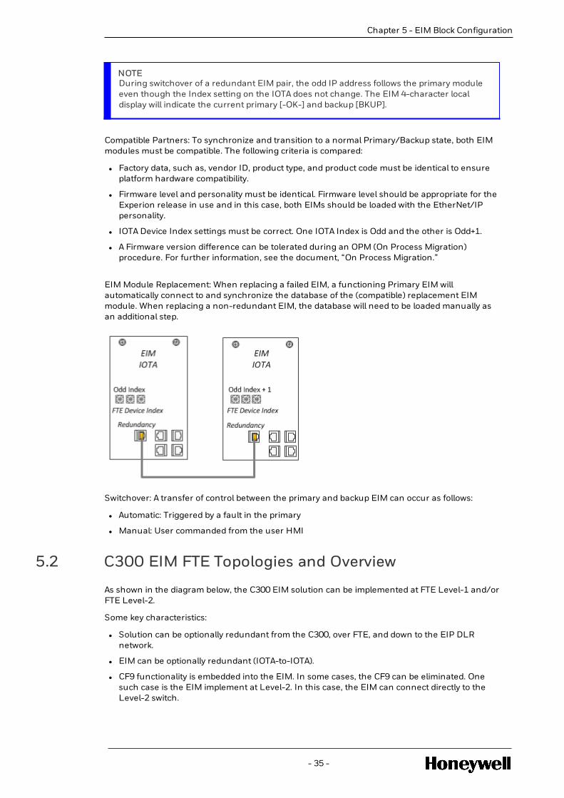
As shown in the diagram below, EIM redundancy is implemented by using two IOTAs (CC-TEIM01)and two EIM modules (CC-PEIM01) connected by a redundancy sync cable. The CAT5 Sync cableenables the primary and backup EIM to maintain synchronization of their database andconfiguration.
Available cable models and lengths:
51305980-8## (CAT5 cable with orange boot) … ## = inches (options: 36, 48, 60, and 84)
FTE Device Index Setting (Establishes the FTE IP Address): One IOTA is assigned the Odd Indexwhile the other IOTA is assigned the (Odd + 1) Index. Either IOTA can be set to the Odd Index aslong as the partner is set to (Odd + 1).
- 34 -
Chapter 5 - EIM Block Configuration
Chapter 5 - EIM Block Configuration
NOTEDuring switchover of a redundant EIM pair, the odd IP address follows the primary moduleeven though the Index setting on the IOTA does not change. The EIM 4-character localdisplay will indicate the current primary [-OK-] and backup [BKUP].
Compatible Partners: To synchronize and transition to a normal Primary/Backup state, both EIMmodules must be compatible. The following criteria is compared:
l Factory data, such as, vendor ID, product type, and product code must be identical to ensureplatform hardware compatibility.
l Firmware level and personality must be identical. Firmware level should be appropriate for theExperion release in use and in this case, both EIMs should be loaded with the EtherNet/IPpersonality.
l IOTA Device Index settings must be correct. One IOTA Index is Odd and the other is Odd+1.
l A Firmware version difference can be tolerated during an OPM (On Process Migration)procedure. For further information, see the document, “On Process Migration.”
EIM Module Replacement: When replacing a failed EIM, a functioning Primary EIM willautomatically connect to and synchronize the database of the (compatible) replacement EIMmodule. When replacing a non-redundant EIM, the database will need to be loaded manually asan additional step.
Switchover: A transfer of control between the primary and backup EIM can occur as follows:
l Automatic: Triggered by a fault in the primary
l Manual: User commanded from the user HMI
5.2 C300 EIM FTE Topologies and Overview
As shown in the diagram below, the C300 EIM solution can be implemented at FTE Level-1 and/orFTE Level-2.
Some key characteristics:
l Solution can be optionally redundant from the C300, over FTE, and down to the EIP DLRnetwork.
l EIM can be optionally redundant (IOTA-to-IOTA).
l CF9 functionality is embedded into the EIM. In some cases, the CF9 can be eliminated. Onesuch case is the EIM implement at Level-2. In this case, the EIM can connect directly to theLevel-2 switch.
- 35 -

l EtherNet/IP firewall is embedded into the EIM downlink. This protects the FTE network fromtraffic on the EIP network. No 3rd party firewalls are required.
l Up to five C300s can be configured to access one EIM.
l Up to five EIMs can be accessed by one C300.
l Solution requires C300 model the CC-TCNT02 loaded with the “Extended” personality.
5.3 C300 EIM Solution - Rules and Caveats
The use of EIP below, will be used as a shorthand for EtherNet/IP™
l When using the EIM EIP solution, the maximum number of FTE Nodes per FTE Community is330.
ATTENTION
One occurrence of a C300 Direct EIP solution on the FTE community will reduce thisnumber to a max of 200.
l Communication with EIP enabled devices and Rockwell Allen Bradley ControlLogix PLC issupported through separate downlink ports of EIM module. EIP ports are isolated from FTEports.
l The EIM EIP network should exist on its own subnet to isolate the EIP network from the FTEcommunity. The use of different EIP/FTE subnets will decouple the EIP node IP addressassignments from the IP addresses used for FTE and non-FTE nodes on the Experion FTEcommunity.
l EIM provides an embedded EIP firewall on the downlink (ETH 1). A 3rd party firewall is notrequired. This built-in firewall capability protects the FTE network from EIP network traffic.
l The EIM module must be loaded with EIP firmware personality to communicate with EIPdevices located on the EIP network.
l The associated C300 must be model CC-PCNT02 and loaded with the 50ms “ExtendedFunctionality” firmware personality.
l An EIM loaded with the EtherNet/IP personality supports only the ETH 1 IOTA downlinkconnector. ETH2 is disabled and is not usable.
- 36 -
Chapter 5 - EIM Block Configuration

Chapter 5 - EIM Block Configuration
l EIP communication is supported between an EIM and EIP devices that are connected in aswitched star, Linear, and/or Device Level Ring topology.
l The Rockwell 1783 ETAP or Stratix 5700 switch is required to connect the EIM ETH 1 port to aDLR (Device Level Ring) Topology. EIM does not support native DLR connection.
l Ring supervisor should be configured in DLR network either on EIP taps (ETAP) or EIP StratixSwitch before physically connecting the ring to maintain the connection between the EIP-compatible devices and the Stratix switch.
l DLR network requires at least one node to be configured as ring supervisor. ETAPs can be usedas a Ring Supervisor and also as a non-supervisor based on Ring supervisor support of Stratixswitch.
l EIP Device Level Ring (DLR) network should be connected only to the DLR ports configured onthe switch
l EIM EIP Ring- Switch Network Topology is supported only with EIP Stratix Switches (Eg: Stratix-5700) with Ring supervisor capability and join as EIP node on the network.
l Multiple EIMs can be connected to a single Device Level Ring (DLR), Linear, and Star, topologynetwork.
l EIM EIP cannot be used to bridge EIP devices across EIP networks.
l The CF9 used by the EIM solution be upgraded to R430 compatibility level (Rev JJ or higher) toenable the proper TCP and UDP ports used for EIP Communications.
l Any Ethernet I/O connected to and used by the Rockwell Allen Bradley ControlLogix PLCshould be connected on an isolated separate downlink ENET card on the Rockwell Allen BradleyControlLogix, and not be connected directly to the Stratix switch network.
l C300- EIM EIP solution and C300 direct EIP solution may co-exist in the same Experion system(but cannot be configured in the same C300 Controller.) Also, the C300 Direct EIP solutionlimits the maximum number of FTE nodes in FTE community to 200.
l Simultaneous use of C300 EIM- EIP and C300- Direct EIP solution in the same C300 controlleris not supported.
l Load of an EIM-EIP application firmware image is required when an EIM is received from thefactory or if it is desired to repurpose an EIM-61850 to server as an EIM-EIP
l Dedicated Network Time source may be required to synchronize clocks across devices andswitches operating on the EIP network. Diagnostics of EIP devices configured through EIM areprocessed in C300 controller and send notifications to Experion server using C300 time source.
l All EIP node display data access is through the C300 (for both solutions). The EIM when loadedwith the EIP personality cannot be directly accessed by the Server or Console station.
l EIM EIP solution must use the approved and mandated Honeywell qualified 3rd party EIPnetwork switches.
l Redundant Rockwell Allen Bradley ControlLogix PLC controller configured in EIM-EIP networktopology must be configured using floating IP mechanism (backup PLC assumes the IPaddress of the failed primary).
ATTENTION
For project planning, always consult the latest specifications document for the most up-to-date information.
- 37 -

5.3.1 EIM EIP Solution – Sample Topologies Using Stratix 8000
- 38 -
Chapter 5 - EIM Block Configuration

Chapter 5 - EIM Block Configuration
5.3.2 EIM EIP Solution – Sample DLR Using 1783-ETAPs
- 39 -

5.3.3 EIM EIP Solution – Sample DLR Using the Stratix 5700
- 40 -
Chapter 5 - EIM Block Configuration

CREATING ETHERNET/IP™ DEVICE, DRIVE, AND I/OMODULE TYPES
You can create Ethernet/IP™ device, drive, and I/O module types by using Electronic Data Sheets(EDS) files or without the EDS files. This section provides the high-level tasks for creatingEthernet/IP™ device, drive, and I/O module types.
6.1 Prerequisites
l If you want to create the Ethernet/IP™ devices, drives, or I/O modules by using the EDS,ensure that you have the appropriate EDS file.
l Ensure that you have all the required device-related specifications, which are available withthe device, before you create the device, drive, or I/O module type.
6.2 Creating Ethernet/IP™ device types using EDS files
Stepnumber
Tasks
1. Open the Parameter Definition Editor (PDE) tool from ControlBuilder. For more information on PDE refer to Parameter DefinitionEditor Reference guide .
2. Select the appropriate EDS file and import it to create a view of theinitial block type / template within PDE.
3. Modify the block parameter definitions as needed.
4. Modify the input, output and configuration assembly definitions asneeded.
- 41 -
CHAPTER
6

6.3 Creating Ethernet/IP™ device types without usingEDS files
Stepnumber
Tasks
1. Open the Parameter Definition Editor (PDE) tool from ControlBuilder. For more information on PDE refer to Parameter DefinitionEditor Reference guide .
2. Specify the input parameters as specified in the device specifications.
3. Specify the output parameters as specified in the devicespecifications.
4. Specify details for configuration parameters as specified in the devicespecifications.
5. Specify assembly details for input, output, and configurationassemblies, which are used for device communication.
6. Define the mapping between the parameters and the assemblies.
6.4 Creating Ethernet/IP™ drive types using EDS files
Prerequisites
l To configure the Ethernet/IP™ device and drive types by using EDS files, ensure that you havethe appropriate EDS file.
l The following sections in the EDS file are critical for device type creation. Ensure that thesedetails are available before using the EDS file.
o Device and Vendor information
o Parameter information
o Assembly information
o Connection information
6.4.1 To create device types using EDS files
1. Click File > New > Type > Ethernet/IP™ Device.
The Library & Type dialog box appears.
2. Select one of the following device types from the Device Type Category list:
l Generic Device
Ethernet/IP™-compatible devices, which are not-I/O devices or drives are categorized asGeneric devices.
l Generic Drive
- 42 -
Chapter 6 - Creating Ethernet/IP™ Device, Drive, and I/O Module Types

Chapter 6 - Creating Ethernet/IP™ Device, Drive, and I/O Module Types
3. Specify the required details depending on the device type and click OK.
l Library name - Indicates the name of the library.
l Type name - Indicates the name of the device type.
l Alarms Support - Enables alarm supportability.
l EDS File - Enables you to select the EDS file to create the device type.
l No. of Input/Output Channels - (Only for I/O) Indicates the number of I/O channels.
l Needs Adapter — Indicates whether the I/O module requires an associated adapter or not.If the I/O module requires an adapter, select the Needs Adapter box.
The following figure displays a sample Library & Type dialog box for reference:
NOTE
In a scenario where multiple I/O modules share a single communication adapter tocommunicate with an Ethernet/IP™ protocol, the Needs Adapter option must beselected. When you select Needs Adapter, while creating the I/O module type, theModule Slot number in Chassis option is enabled in the configuration form the I/Omodule instance. If you are using an adapter, which is not from the AENT1738series, you can specify the unique slot number details in the Module Slot numberin Chassis field and avoid creating a separate adapter.
4. Click Browse (... icon) to select the EDS file.
5. Select the EDS file and click Open.
6. In the Device Type Configuration dialog box, select the following Assembly types, as shown inthe figure, and click OK:
l Input
l Output
l Configuration
- 43 -

NOTE
There might be more than one Input, Output, and Configuration Assembly types.However, ensure that you select one instance of Input, one instance of Output, andone instance of Configuration Assembly types per your requirement.
The Parameter Definition Editor (PDE) grid for configuring the device type parametersappears. The PDE grid consists of the following tabs with the relevant details, which arepopulated from the EDS file.
l Forms layout
l Enumerations
l Input Parameters
l Output Parameters
l Configuration Parameters
l Assemblies
l Alarms
Scaling Configuration Tab
The following image illustrates the Scaling Configuration tab.
- 44 -
Chapter 6 - Creating Ethernet/IP™ Device, Drive, and I/O Module Types

Chapter 6 - Creating Ethernet/IP™ Device, Drive, and I/O Module Types
Parameter name: It is the custom parameter defined for input and output.o Type: It defines the parameter type.o Low Range: It defines the lowest limit for the parameter value.o High Range: It defines the highest limit for the parameter value.o Scale Factor: It defines the ratio of the value for scalingo Bias: It defines the calibrated engineering units.
Configuration
Configure custom parameters using the PDE (Parameter Definition Editor) tool. For moreinformation on PDE refer to Parameter Definition Editor Reference guide .
By default, scaling parameters are not available in the configuration form. To display it inthe configuration form, manually add the scaling parameters in the form layout of the EIPgeneric device PDE.
Form layout configuring for custom output scaling parameters
1. Create a generic device.
2. Add and configure custom parameters.
3. Configure scaling parameters for custom output parameters under Data Command tab,in the Form Layout page.
4. Save and close the PDE.
- 45 -

To view and modify the scaling parameters in EIP generic device instances
1. Create an instance of the generic device.
2. Open the configuration form of the generic device instance from Control Builder’sProject Tree view.
3. Select the Data/Command tab to view scaling parameters.
NOTE
You can modify scaling parameters from the configuration form.
Configuration Parameters for scalar (non-arrayed) custom parameters
o PARAMNAME.HIGHRANGEo PARAMNAME.LOWRANGEo PARAMNAME.SCALEFACTORo PARAMNAME.BIASo PARAMNAME.FLOATVALUE
For more information, see Control Builder Parameter Reference Guides_EPDOC-XX18-en-505A.pdf.
Configuration Parameters for arrayed custom parameters
For arrayed parameters, the array size will be defined based on the custom parameter’ssize.
- 46 -
Chapter 6 - Creating Ethernet/IP™ Device, Drive, and I/O Module Types

Chapter 6 - Creating Ethernet/IP™ Device, Drive, and I/O Module Types
Parametername:
PARAMNAME [Index].HIGHRANGE
Specific to Block: Generic Device
Description: Scaling parameter for setting high range
Data Type: FLOAT64
Range: -1.7E+308 to +1.7E+308
# Enumtext
Size inbytes
Min. RawValue
Max. Rawvalue
Default: NaN
Config Load:
Access Lock: Engineer
Residence: CEE
RelatedParameters:
Remarks:
Parametername:
PARAMNAME [Index].LOWRANGE
Specific to Block: Generic Device
Description: Scaling parameter for setting low range
Data Type: FLOAT64
Range: -1.7E+308 to +1.7E+308
Generic Device
# Enumtext
Size inbytes
Min. RawValue
Max. Rawvalue
Default: NaN
Config Load:
Access Lock: Engineer
Residence: CEE
- 47 -

Parametername:
PARAMNAME [Index].LOWRANGE
RelatedParameters:
Remarks:
Parametername:
PARAMNAME [Index].SCALEFACTOR
Specific toBlock:
Generic Device
Description:
Data Type: FLOAT32
Range: -1.7E+308 to +1.7E+308
# Enumtext
Size inbytes
Min. RawValue
Max. Rawvalue
Default: 1
Config Load:
Access Lock: Engineer
Residence: CEE
RelatedParameters:
Remarks:
- 48 -
Chapter 6 - Creating Ethernet/IP™ Device, Drive, and I/O Module Types

Chapter 6 - Creating Ethernet/IP™ Device, Drive, and I/O Module Types
Parametername:
PARAMNAME [Index].BIAS
Specific to Block: Generic Device
Description:
Data Type: FLOAT32
Range: -1.7E+308 to +1.7E+308
# Enumtext
Size inbytes
Min. RawValue
Max. RawValue
Default: 0
Config Load:
Access Lock: Engineer
Residence: CEE
RelatedParameters:
Remarks:
Parameter name: PARAMNAME [Index].FLOATVALUE
Specific to Block: Generic Device
Description:
Data Type: FLOAT64
Range: -1.7E+308 to +1.7E+308
# Enumtext
Size inbytes
Min. RawValue
Max. Rawvalue
Default: 0
Config Load:
Access Lock: Engineer
Residence: CEE
RelatedParameters:
Remarks:
- 49 -

Where ‘PARAMNAME’ is the Custom parameter name and ‘Index’ is the index of arrayedcustom parameter.
NOTE
Scaling of numeric values (including floating point) alone is supported.
NOTE
Mandatory parameters will be displayed as ReadOnly. The Configurationparameters will be created for the selected configuration assembly.
Ensure that you do not delete any pre-populated parameter details. If required, youcan add additional parameter to the existing list.
NOTE
Scaling is applicable only for generic device.
For more information about the various tabs in the PDE grid, see Parameter Definition Editor(PDE) Grid Tabs.
7. Click all the tabs, and verify the details.
For more information about the various tabs in the PDE grid, see Parameter Definition Editor(PDE) Grid Tabs.
8. Click File > Save to save the device configuration.
After saving, the new device type will be populated in the library with an input and an outputchannel.
You can use the created device type from the library to configure new devices or drives.
6.5 Creating Ethernet/IP™ drive types without EDS files
6.5.1 Prerequisites
Ensure that the following details are available before creating the device and drive types:
l Device and Vendor information
l Parameter information
l Assembly information
l Connection information
- 50 -
Chapter 6 - Creating Ethernet/IP™ Device, Drive, and I/O Module Types

Chapter 6 - Creating Ethernet/IP™ Device, Drive, and I/O Module Types
6.5.2 To create drive types without EDS files
1. Click File > New > Type > Ethernet/IP™ Device.
The Library & Type dialog box appears.
2. Select one of the following device types from the Device Type Category list:
l Generic DeviceEthernet/IP™-compatible devices, which are not-I/O devices or drives arecategorized as Generic devices.
Generic Drive
3. Specify the required details depending on the device type and click OK.
l Library name - Indicates the name of the library.
l Type name - Indicates the name of the device type.
l Alarms Support - Enable alarm supportability.
l No. of Input/Output Channels - (Only for Generic devices) Indicates the number of I/Ochannels.
The following figure displays a sample Library & Type dialog box for reference.
The Parameter Definition Editor (PDE) grid for configuring the device type parametersappears. The PDE grid consists of the following tabs:
l Forms layout tab
l Enumerations tab
l Input Parameters tab
l Output Parameters tab
l Configuration Parameters tab
l Alarms tab
l Channel Status tab
l Scaling
For more information on Scaling refer Scaling support for custom parameters section.
- 51 -

4. Specify the following parameter details appropriately. Refer to the specifications of the devicefor information about the parameter details.
l Enter the input parameters on the Input Parameters tab.
l Enter the output parameters on the Output Parameters tab.
l Enter the configuration parameters on the Configuration Parameters tab.
NOTE
Mandatory parameters will be displayed as ReadOnly. The Configurationparameters will be created for the selected configuration assembly.
Ensure that you do not delete any pre-populated parameter details. If required, youcan add additional parameter to the existing list.
5. Enter the assembly details for input, output, and configuration parameters, which will be usedfor device communication.
6. Specify the assembly instance for each assembly and define the mapping between theparameters and the assembly.
To specify the assembly instance for an assembly and to define the mapping between theparameters and the assembly:
a. Click the cell in the Assembly Members column.
b. Click the hotspot icon in the cell.
The Assembly Members window appears.
c. Enter the following parameter details for the assembly:
l Parameter name
l Parameter Index
l Byte Offset
l Bit Offset
l Size (in bits)
The following figure displays a sample Assembly Mapping window for reference.
- 52 -
Chapter 6 - Creating Ethernet/IP™ Device, Drive, and I/O Module Types

Chapter 6 - Creating Ethernet/IP™ Device, Drive, and I/O Module Types
d. Click OK.
7. Click all the tabs and specify the details on the tabs per your requirement.
For more information about the various tabs in the PDE grid, see Parameter Definition Editor(PDE) Grid Tabs.
8. Click File > Save to save the device configuration.
After saving, the new device type will be populated in the library with an input and an outputchannel.
You can use the created device type from the library to configure new devices or drives.
6.6 Creating Ethernet/IP™ I/O module types using EDSfiles
6.6.1 Prerequisites
l To configure the Ethernet/IP™ I/O module types by using the EDS files, ensure that you havethe appropriate EDS file.
l The following sections in the EDS file are critical for creating device types. Ensure that thesedetails are available before using the EDS file.
o Device and Vendor information
o Parameter information
o Assembly information
o Connection information
- 53 -

6.6.2 To create Ethernet/IP™ I/O module types using EDS files
1. Click File > New > Type > Ethernet/IP™ Device.
The Library & Type dialog box appears.
2. Select IO Module from the Device Type Category list.
3. Specify the following details and click OK.
l Library name — Indicates the name of the library.
l Type name — Indicates the name of the I/O device type.
l EDS File — Enables you to select the EDS file to create the device.
l I/O Module Type — Lists the I/O module types:o Analog Inputo Analog Outputo Digital Inputo Digital Output
l No. of Input/Output Channels — Indicates the number of I/O channels.
l Alarms Support — Enables alarm supportability.
l Status Support— Enables you to indicate whether you want to monitor the status ofvarious channels or not.
l Needs Adapter — Indicates whether the I/O module requires an associated adapter ornot. If the I/O module requires an adapter, select the Needs Adapter box.
The following figure displays a sample of the Library & Type dialog box for reference.
NOTE
In a scenario where multiple I/O modules share a single communication adapter tocommunicate with an Ethernet/IP™ protocol, the Needs Adapter option must beselected. When you select Needs Adapter, while creating the I/O module type, theModule Slot number in Chassis option is enabled in the configuration form the I/Omodule instance. If you are using an adapter, which is not from the AENT1738series, you can specify the unique slot number details in the Module Slot numberin Chassis field and avoid creating a separate adapter.
4. Click Browse (... icon) to select the required EDS file.
5. Select the EDS file and click Open.
- 54 -
Chapter 6 - Creating Ethernet/IP™ Device, Drive, and I/O Module Types

Chapter 6 - Creating Ethernet/IP™ Device, Drive, and I/O Module Types
6. In the Device Type Configuration dialog box, select the following Assembly types, as shown inthe figure, and click OK:
l Input
l Output
l Configuration
NOTE
There might be more than one Input, Output, and Configuration assembly types.However, ensure that you select one instance of Input, one instance of Output, andone instance of Configuration Assembly types per your requirement.
If the I/O module type is an input module, it would not require output parameters.Similarly, if the I/O module type is an output module, it would not require inputparameters.
The Parameter Definition Editor (PDE) grid for configuring the device type parametersappears. The PDE grid consists of the following tabs with the relevant details, which arepopulated from the EDS file.
l Forms layout
l Enumerations
l Input Parameters
l Output Parameters
l Configuration Parameters
l Assemblies
l Alarms tab
l Channel Status tab
NOTE
Mandatory parameters will be displayed as ReadOnly. The Configurationparameters will be created for the selected configuration assembly.
Ensure that you do not delete any pre-populated parameter details. If required, youcan add additional parameter to the existing list.
For more information about the various tabs in the PDE grid, see Parameter Definition Editor(PDE) Grid Tabs
- 55 -

7. Click all the tabs, and verify the details.
For more information about the various tabs in the PDE grid, see Parameter Definition Editor(PDE) Grid Tabs.
8. Click File > Save to save the device configuration.
After saving, the new I/O device type will be populated in the library with an input and anoutput channel.
You can use the created I/O device type from the library to configure new devices.
6.7 Creating Ethernet/IP™ I/O module types without EDSfiles
6.7.1 Prerequisites
Ensure that the following details are available before creating the device and drive types:
l Device and Vendor information
l Parameter information
l Assembly information
l Connection information
6.7.2 To create I/O module types without EDS files
1. Click File > New > Type > Ethernet/IP™ Device.
The Library & Type dialog box appears.
2. Select IO Module from the Device Type Category list.
3. Specify the following details and click OK.
l Library name - Indicates the name of the library.
l Type name - Indicates the name of the device type.
l I/O Module Type - Lists the I/O module types:o Analog Inputo Analog Outputo Digital Inputo Digital Output
l No. of Input/Output Channels - Indicates the number of I/O channels.
l Alarms Support - Enables alarm supportability.
l Status Support - Enables you to indicate whether you want to monitor the status ofvarious channels or not.
l Needs Adapter - Indicates whether the I/O module requires an associated adapter or not.If the I/O module requires an adapter, select the Needs Adapter box.
The following figure displays a sample Library & Type dialog box:
- 56 -
Chapter 6 - Creating Ethernet/IP™ Device, Drive, and I/O Module Types
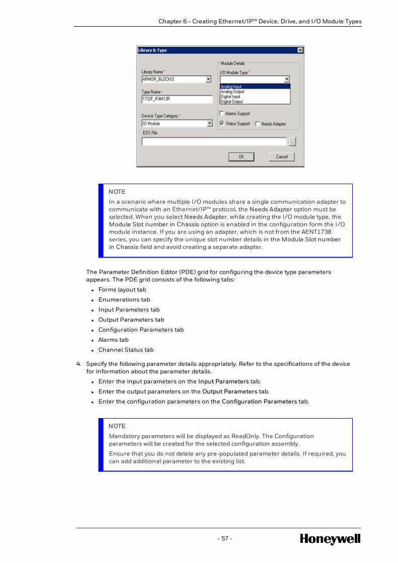
Chapter 6 - Creating Ethernet/IP™ Device, Drive, and I/O Module Types
NOTE
In a scenario where multiple I/O modules share a single communication adapter tocommunicate with an Ethernet/IP™ protocol, the Needs Adapter option must beselected. When you select Needs Adapter, while creating the I/O module type, theModule Slot number in Chassis option is enabled in the configuration form the I/Omodule instance. If you are using an adapter, which is not from the AENT1738series, you can specify the unique slot number details in the Module Slot numberin Chassis field and avoid creating a separate adapter.
The Parameter Definition Editor (PDE) grid for configuring the device type parametersappears. The PDE grid consists of the following tabs:
l Forms layout tab
l Enumerations tab
l Input Parameters tab
l Output Parameters tab
l Configuration Parameters tab
l Alarms tab
l Channel Status tab
4. Specify the following parameter details appropriately. Refer to the specifications of the devicefor information about the parameter details.
l Enter the input parameters on the Input Parameters tab.
l Enter the output parameters on the Output Parameters tab.
l Enter the configuration parameters on the Configuration Parameters tab.
NOTE
Mandatory parameters will be displayed as ReadOnly. The Configurationparameters will be created for the selected configuration assembly.
Ensure that you do not delete any pre-populated parameter details. If required, youcan add additional parameter to the existing list.
- 57 -

5. Enter the assembly details for input, output, and configuration parameters, which will be usedfor device communication.
6. Specify the parameters for each assembly and define the mapping between the parametersand the assembly
To specify the parameters for an assembly and to define the mapping between theparameters and the assembly:
a. Click the cell in the Assembly Members column.
b. Click the hotspot icon in the cell.
The Assembly Members window is displayed.
c. Enter the following parameter details of the assembly:
l Parameter name
l Parameter Index
l Byte Offset
l Bit Offset
l Size (in bits)
d. Click OK.
7. Click all the tabs and specify the details on the tabs per your requirement.
For more information about the various tabs in the PDE grid, see Parameter Definition Editor(PDE) Grid Tabs.
8. Click File > Save to save the device configuration.
After saving, the new I/O device type will be populated in the library with an input and anoutput channel.
You can use the created I/O device type from the library to configure new devices.
6.8 Configuring data link parameters
The module configurations of PowerFlex drive and the relay (E3 and E3 plus) can be edited. Thesemodules have options to edit and configure data link parameters through the EDS Import Tool.Editing the default configurations might lead to undesirable results. Therefore, if you want toconfigure data link parameters per the customer’s requirement, ensure that you save a copy ofthe existing default configuration as a backup copy for future reference and use.
In PowerFlex drive modules, the following parameters in the Drive Status 2 section and DriveCommand 2 section are preconfigured data link parameters. Ensure that you configure theseparameters using Drive Explorer. However, if you want to use a different set of data linkparameters or remove the existing preconfigured data link parameters, you mustconfigure/remove the required set of parameters appropriately by using the EDS Import Tool.
NOTE
Before you configure/remove the parameters, ensure that you take a backup of the existingdefault configuration for future use.
Drive Status 2
- 58 -
Chapter 6 - Creating Ethernet/IP™ Device, Drive, and I/O Module Types

Chapter 6 - Creating Ethernet/IP™ Device, Drive, and I/O Module Types
l Stop Owner (STOPOWNER)
l Start Owner (STATROWNER)
l Jog Owner (JOGOWNER)
l Clear Fault Owner (CLRFLTOWNER)
l Speed Reference Source (SPDREFSRC)
l Last Start Source (LASTSTARTSRC)
l Last Stop Source (LASTSTOPSRC)
l Start Inhibits (STRTINH)
l Last Fault Code (LASTFLTCODE)
l Fault Frequency (Hz) (FAULTFREQ)
l Fault Amps (A) (FAULTAMPS)
l Fault Bus Volts (FLTBUSV)
l Elapsed Megawatt Hour (MWh)(ELAPSEDMWH)
l Elapsed Kilowatt Hour (ELAPSEDMWH)
l Elapsed Run Time (Hrs) (ELAPSEDKWH)
l Output Current (A) (OPCURRENT)
Drive Command 2
l Stop Mode B (STOPMODEB)
l Speed Reference B, Setpoint (SPDREFBSTPT)
l Speed Reference Scale (SPDREFSCALE)
l Jog Speed 1 (JOGSPD1)
l Jog Speed 2 (JOGSPD2)
l Maximum Forward Speed (MAXFWDSPD)
l Maximum Reverse Speed (MAXREVSPD)
l Acceleration Time 1 (Secs) (ACCELTIME1)
l Acceleration Time 2 (Secs) (ACCELTIME2)
l Deceleration Time 1 (Secs)(DECELTIME1)
l Deceleration Time 2(Secs)(DECELTIME2)
l Overspeed Limit (OVERSPDLIMIT)
l Jog Accel. Dcccl. Time(Secs) (JOGADTIME)
l Zero Speed Limit (ZEROSPDLIMIT)
6.8.1 Prerequisites
l Ensure that you back up the existing default configuration for future reference or use.
- 59 -

6.8.2 To configure data link parameters
1. Open the device configuration from the Library.
The PDE grid with the configured details is displayed.
2. Click File > Save As to save a copy of the configuration details.
By saving a copy and working on the new copy, you are retaining the original defaultconfiguration as is.
3. Edit the data link parameters appropriately on the Input Parameters tab.
4. Edit the data link parameters appropriately on the Output Parameters tab.
5. Edit the parameters for each assembly accordingly on the Assemblies tab. To edit theparameters for each assembly and to define the mapping between the parameters and theassembly:
a. Click the cell in the Assembly Members column.
b. Click the hotspot icon in the cell.
The Assembly Members window is displayed.
c. Enter the following parameter details of the assembly:
l Parameter name
l Parameter Index
l Byte Offset
l Bit Offset
l Size (in bits)
d. Click OK.
6. Click File > Save to save the configuration details.
6.8.3 Results
The required data link parameters are configured.
- 60 -
Chapter 6 - Creating Ethernet/IP™ Device, Drive, and I/O Module Types

INTRODUCTION TO UDT CONCEPTS
Definitions, Acronyms, and Abbreviations:
l UDT: User defined Tag.
l Aggregate\Multi-parameter UDT: A User defined Tag with Single or multiple fields withdifferent data types.
l Scalar UDT: A Tag with only one parameter of a particular Type.
l What is a ControlLogix UDT and How is it Used?
l C300 UDT – Input Parameters & Output Parameters
l C300 UDT - Data Types Supported in Experion R501
l UDT Template vs. Instance Concept
l C300 CPU Loading Due to UDT Points
l C300 and ControlLogix integration
l Configuring ControlLogix Tags in peer references from Experion strategies
7.1 What is a ControlLogix UDT and How is it Used?
UDT (User-Defined Data Type) is a ControlLogix function that allows you to create a single tag tohold multiple data fields called members (or parameters). A UDT is used to organize related datainto a single place enabling more efficient PLC programming. One common use case is to createspecial UDTs for objects that are common to the ladder program, site, and application.
Example Use Case : Assume that you want to create a UDT that could be used as a data templatefor all motors associated with the application. You might create a UDT named “Motor Data Type”that consisted of a mixture of input and output parameters of different data types (Integer, Float,Boolean, String, etc). For a motor this UDT data structure could include numerous status bits,fault timers, run cycle counters, etc. Once the UDT exists, you could then create a unique tag (onefor each individual motor) that would be assigned to use the “Motor Data Type” UDT template.
The following table shows the UDT Capacity Specification that are supported in Experion R511.
Experion User Defined Type (UDTs) Capacity Specification LimitMaximum number of parameters per Multi-parameter/ Aggregate UDT (User DefinedTypes)
64
Maximum input size of a Multi-parameter UDT (User Defined Types) to readparameters
480bytes
Maximum output data size of a Multi-parameter UDT (User Defined Types) to writeparameters
256bytes
- 61 -
CHAPTER
7

Experion User Defined Type (UDTs) Capacity Specification LimitMaximum number of parameters per scalar UDT (User Defined Types) 1
Maximum input size of a Scalar-parameter UDT (User Defined Types) to readparameters
4 bytes
Maximum output size of a Scalar-parameter UDT (User Defined Types) to writeparameters
4 bytes
Maximum Multi-parameter User Defined Types (UDTs) per UOC to all ControlLogixPLCs combined
65
NOTE
1. For the Aggregate UDT's, the entire UDT Read consumes one Read Resource whereas the UDT Write is based on a single parameter where as every parameterconfigured as write consumes one write resource.
2. Each UDT consumes one Read Resource, irrespective of whether it is configuredfor Read Only or Write Only. For Example, if we have a UDT with two parameters,both of which have been configured for Write, that UDT consumes 1 Read Resourceand two write resources.
7.2 UDT – Input Parameters & Output Parameters
A UDT can be configured to have input parameters only, output parameters only, or anycombination of both inputs and outputs under the same UDT.
Definition of input vs. output parameters.
Input Parameter: A UDT input parameter reads data from a UDT tag in the ControlLogix processor.
Output Parameter: A UDT output parameter from a UDT tag writes data from the C300 to a UDT inthe ControlLogix processor.
NOTE
You must ensure that the UDT structure (parameters, data types, and array dimensions forarrays) match the UDT structure in the ControlLogix processor. Mismatches result inunpredictable behavior.
7.3 UDT - Data Types Supported in Experion R511
The following table shows the UDT data types that are supported in Experion R511. It also indicatesthe bytes consumed by the associated input/read or output/write parameters.
Arrayed parameters for the data types mentioned in the preceding table are supported.
ATTENTION
The maximum size per ControlLogix UDT for a read operation is 480 bytes and 256 bytes fora write operation.
- 62 -
Chapter 7 - Introduction to UDT Concepts

Chapter 7 - Introduction to UDT Concepts
Data Type DescriptionBytes consumed perinput or output parameter
SupportedOperations
BOOLEAN 1 –byte… Logical Booleanwith values TRUE and FALSE
1 Read &Write
INT8 8–bit integer 1 Read &Write
INT16 16–bit integer 2 Read &Write
INT32 32–bit integer 4 Read &Write
FLOAT32 32–bit floating point 4 Read &Write
STRING STRING See Note below Read only
NOTE
When the STRING data type is selected for a parameter, the user must also enter a numberinto the Size entry field that indicates the number of bytes/characters that are associatedwith the STRING parameter.
Example 1:
When a Tag Type STRING is created in ControlLogix, by default it takes up 88 bytes. This 88Bytes can further be visualized as follows:
1. 4bytes of Length - This represents the size of Actual data within the Buffer thatfollows. This is user configurable in CLX.
2. 82 Bytes of buffer.
3. 2bytes of Padding.
So, a String will consume 88 bytes of the total 480 bytes available for the UDT, irrespective ofthe Size.
Example 2:
Memory Layout of UDT ExampleTag with the following structure :
l Param_1 of type INT16
l Param_2 of type INT32
l Param_3 of type BOOLEAN
l Param_4 of String type
l Param_5 of type int16
l Param_6 of type INT32
- 63 -

ParameterNames
Datatype ArraySize
Memory Layout InputBytes
Param_1 INT16 0 2 bytes of data followed by2 bytes of padding
4
Param_2 INT32 6 24 bytes 24
Param_3 BOOLEAN 0 One byte of data followedby 3 bytes of padding
4
Param_4 String 0 88 bytes. The default sizeof string is 88
88
Param_5 INT16 5 10 bytes of datam followedby 2 bytes of padding
12
Param_6 INT32 0 4 bytes of data 4
Total 136
7.4 UDT Template vs. Instance Concept
Template: You can create UDTs (User-Defined Data Types) that have a user defined structure (agiven number of parameters of specific data types). Each UDT (template) is then assigned a namethat best identifies the purpose of the UDT (for example, Solenoid_Valve, LV_Motor, MV_Drive,etc.).
Instance: You can use these templates to create instances of the UDT. For example, you cancreate a Tag (Motor_101) and assign it to the LV_Motor UDT.
Motor_101 will then be a tag with a structure as defined by the LV_Motor UDT and associated witha particular “physical” low voltage motor. Additional motor instances (such as Motor_102, Motor_103, etc.) can be created for other “physical motors” and be assigned to use the same LV_MotorUDT.
This concept is applicable to the creation of UDTs on the ControlLogix as well as the C300 side.
7.5 CPU Loading Due to UDT Points
RPI parameter: The RPI (Requested Packet Interval) parameter is used to set the update rate for allread operations assigned to a given UDT point. The user can enter an integer value in the range of100 to 2000 milli-seconds (should be a value that is appropriate for the application).
As shown in the calculation below, lower RPI settings (faster update rates) will consumeproportionally more of the available CPU processing resource.
Note that write operations are handled differently from read operations.
Calculation : (C300 processing resource used by a UDT configuration)
% CPU_used = Number of UDT points * (0.0375) + (0.0786) * Total number of READs per second
- 64 -
Chapter 7 - Introduction to UDT Concepts

Chapter 7 - Introduction to UDT Concepts
NOTE
The calculation above considers the C300 %CPU used for UDT points only. A completecalculation for C300 loading must consider all other items that will consume CPU processingresources (like standard I/O, FF interfaces, peer-to-peer, total number of CMs, etc.).
In R430 and R431 the default value of RPI is 250 ms. From R501, the RPI Values are Clamped to theclosest Allowable UDT RPI Values. Clamping happens during configuration time. No message isshown, but as soon as user enters the value and hits enter, the value changes to 100 or 200 orother accordingly.
Allowable UDT RPI values: 100, 200, 500, 1000, 2000 ms.
Default value: 200 ms.
Although the RPI parameter is an integer with the range 50 to 65,536, the entered value will berounded to the nearest of the five supported values above.
Figure 7.1 RPI Parameter- Entered vs Rounded Value
7.6 C300 and ControlLogix integration
Starting with Experion R430, the C300 controller can efficiently integrate with the ControlLogixcontrol system. The ControlLogix processors store data in the form of tags. This integrationsupports the following operations:
l Reading the User-Defined Tags (UDTs) from the ControlLogix Programmable logic controller(PLC).
l Referencing the UDTs in Experion strategies.
l Writing the updated UDTs to the ControlLogix PLC.
The Control Builder provides configuration options, which facilitate the integration of C300 and theControlLogix control system. The following table lists the high-level tasks for configuring the C300and ControlLogix integration:
Task Description
Step 1:Configuring theControlLogixgateway
To establish a connection between C300 controllers andControlLogix PLCs you must configure the requiredconnection settings.
Step 2: To read UDTs from the ControlLogix PLC and to write the
- 65 -

Task Description
ConfiguringControlLogixuser-defined tagblocks
UDTs to the ControlLogix PLC, you must define tagstructures that match the tag structures in thecorresponding ControlLogix PLCs.
You can create the required tag structure by configuring aUDT type in Control Builder.
Step3 : Definingthe ControlLogixtag access
Create an instance of the ControlLogix UDT in a ControlModule. To ensure that the required UDTs, which you wantto access for performing a read or write operation aremapped to the appropriate ControlLogix PLC, you mustspecify the following :
l The gateway details, which represent the ControlLogixPLC.
l The tag name of the UDT (on the ControlLogix PLC)that you want to access.
Step 4: UsingAggregate orScalar TagInstance for Readand WriteOperations
After creating an instance of the UDT block, you canconnect it to other required blocks to perform a read orwrite operation. Load the Control Module configuration.
7.7 Configuring ControlLogix Tags in peer referencesfrom Experion strategies
This topic lists the sequence of tasks required to configure ControlLogix UDTs in peer referencesfrom anExperion strategy.
Consider the following sample scenario:
l CLX1 is a ControlLogix PLC
l CLX_tag1 is a UDT defined in CLX1.
l You want to access CLX_tag1 as a peer reference in anExperion strategy from C300.
The following illustration represents the preceding scenario:
Figure 7.2 Illustrating a sample scenario for ControlLogix tag access
- 66 -
Chapter 7 - Introduction to UDT Concepts

Chapter 7 - Introduction to UDT Concepts
The following procedure lists the high—level tasks that must be performed to configureControlLogix UDTs in peer references from anExperion strategy.
NOTE
Accessing of arrayed parameter defined as Aggregate tag which is not defined inside theUser Defined Data type (UDT), is not supported. Individual element of the array can beaccessed as Scalar tag.
7.7.1 Prerequisites
l Ensure that the ControlLogix control systems are installed and configured in the network.
l (Optional) If you want to configure tag browsing, ensure that you install the Allan Bradley OPCServer from MatrikonOPC. For more information, see the MatrikonOPC Server for AllenBradley PLCs Online Help.
7.7.2 To configure ControlLogix Tags in peer references fromExperion strategies
1. Configure an instance of ControlLogix gateway (CLX1_gateway) in Control Builder. TheControl Logix gateway acts as a proxy for one ControlLogix processor. For more informationabout configuring gateways, see Configuring the ControlLogix Gateway block.
Figure 7.3 Step 1 — Configuring the ControlLogix gateway
- 67 -

2. Create a UDT in Control Builder, which represents the structure of the UDT (CLX_tag1). CLX_tag1 is defined in the ControlLogix PLC (CLX1). For more information about creating customdata type blocks, see Creating Control Logix Aggregate UDT Type.
Figure 7.4 Step2 — Configuring a custom UDT block type in Control Builder
3. Create an instance (CL_UDTtag) of the custom UDT block type (CL_UDT) in a Control Module(CM_CLX_data). Define the gateway and ControlLogix tag details for CL_UDTtag. For moreinformation about defining the tag and the gateway details, see Defining the ControlLogix tagaccess
Figure 7.5 Step3 — Creating an instance of the UDT block and defining the ControlLogix tagaccess
- 68 -
Chapter 7 - Introduction to UDT Concepts
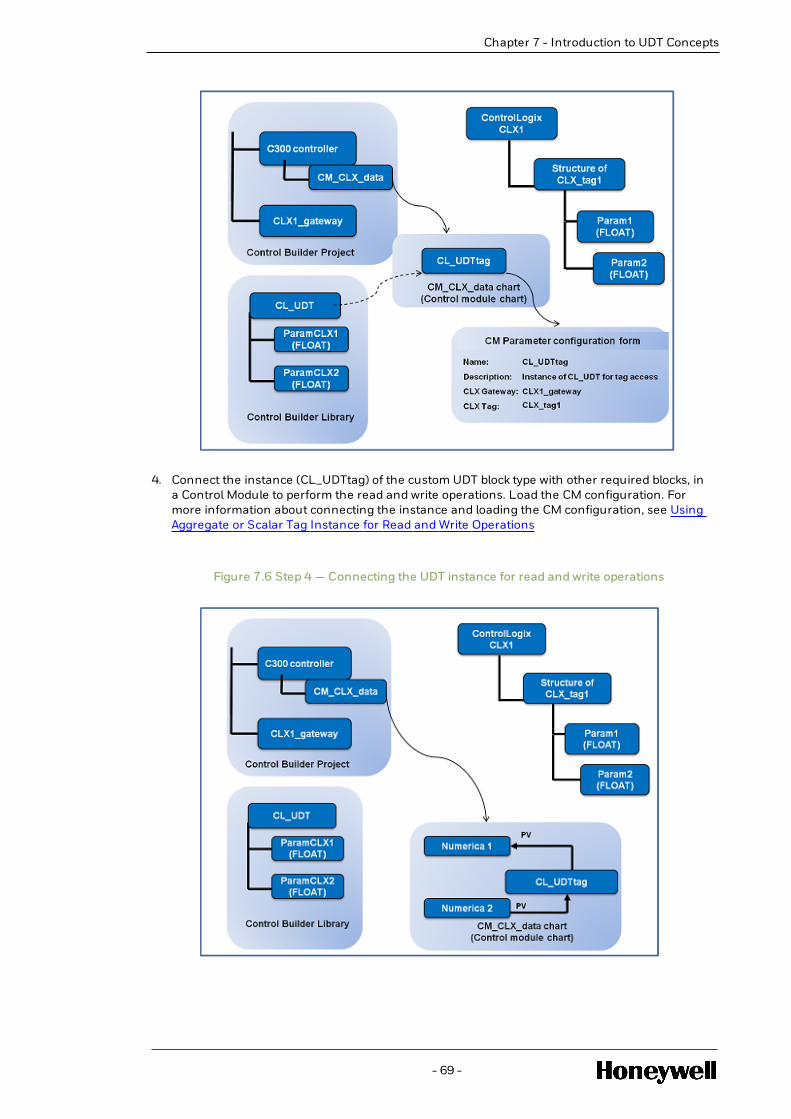
Chapter 7 - Introduction to UDT Concepts
4. Connect the instance (CL_UDTtag) of the custom UDT block type with other required blocks, ina Control Module to perform the read and write operations. Load the CM configuration. Formore information about connecting the instance and loading the CM configuration, see UsingAggregate or Scalar Tag Instance for Read and Write Operations
Figure 7.6 Step 4 — Connecting the UDT instance for read and write operations
- 69 -

l Configuring the ControlLogix Gateway block
l Creating Control Logix Aggregate UDT Type
l Creating Control Logix Scalar UDT Type
l Defining the ControlLogix tag access
l Using Aggregate or Scalar Tag Instance for Read and Write Operations
7.7.3 Configuring the ControlLogix Gateway block
To establish a connection between C300 and the ControlLogix PLC, you must define theconnectivity settings. You can specify the connectivity settings by creating a Control Logix gatewayblock in the Control Builder. Each Control Logix gateway block represents an instance of anequivalent ControlLogix PLC.
If you have multiple ControlLogix PLCs, ensure that for each PLC, you configure a correspondingControlLogix gateway. For more information about the number of ControlLogix gateways that youcan configure for one C300, see the Specifications document.
The gateway contains the ControlLogix PLC connectivity—related information such as the IPaddress and slot number, which is required to access the ControlLogix PLC.
For example, for the ControlLogix PLC, CLX1, you can configure a gateway named CLX1_gatewaywith the IP address and the slot number details.
To configure a ControlLogix gateway block
1. Click File > New > Control Logix block.
The ControlLogix gateway configuration form appears.
2. On the Main tab, specify the details for the ControlLogix gateway, which include the following:
l Tag Name – For example, CLX1_gateway
l Item Name — For example, ControlLogixCLX1_gateway
l IP address — The IP address of the EtherNet Communication Interface (ENET) module.For example, 10.10.10.1.
l Slot number — The slot number details of the ControlLogix PLC. For example, 3.
l Tag Browsing Configuration:
a. Through Matrikon OPC Server option:
Specify the Matrikon OPC Host Name, Matrikon OPC Prog Id, AB Plugin Name, and PLCObject Name details to enable tag browsing through Matrikon OPC Server option. SeeTag browsing section for more details.
ATTENTION
Tag browsing is optional. If you want to enable the tag browsing feature,ensure that you install and configure the Allan Bradley OPC Server fromMatrikonOPC. For more information about the Matrikon OPC configuration,see MatrikonOPC Server for Allen Bradley PLCs Online Help.
o Tag Browsing Configuration — Specify the Matrikon OPC Host Name, MatrikonOPC Prog Id, AB Plugin Name, and PLC Object Name details to enable tagbrowsing through Matrikon OPC Server option. See Tag browsing section formore details.
- 70 -
Chapter 7 - Introduction to UDT Concepts

Chapter 7 - Introduction to UDT Concepts
ATTENTION
Tag browsing is optional. If you want to enable the tag browsingfeature, ensure that you install and configure the Allan Bradley OPCServer from MatrikonOPC. For more information about the MatrikonOPC configuration, see MatrikonOPC Server for Allen Bradley PLCsOnline Help.o Matrikon OPC Host Name — The host name of the server where
the Matrikon OPC server is installed.o Matrikon OPC Prog Id — The Program ID specified during
Matrikon OPC configuration.o Matrikon OPC Prog Id — The Program ID specified during
Matrikon OPC configuration.o AB Plugin Name — The name of the plugin used in the Matrikon
OPC configuration.o PLC Object Name — The object name specified during the
Matrikon OPC configuration. During Matrikon OPCconfiguration, an object name is used to represent theControlLogix PLC. Specify the same object name.
o For more information about the parameters, see the Control Builder ParameterReference.o The MatrikonOPC Server for Allen Bradley PLCs can be installed on
another computer or the Experion node (server/station/flex console).o DCOM configuration is required when connecting to an OPC server located
on another computer.o If Matrikon OPC server is installed on the Experion server and you are
configuring on another Experion node, such as flex/station/console,ensure that you complete the DCOM configuration for the MartikonOPCserver. For more information about configuring DCOM, see SupplementaryInstallation Tasks Guide.
b. Through Associate L5X file option:
See Tag browsing section for more details on tag browsing through Associate L5X fileoption.
3. Complete the required details on all the other tabs and click OK.
Results
The ControlLogix gateway (CLX1_gateway) block is configured.
Next steps
After you configure the ControlLogix gateway block, you must create a UDT block. For moreinformation about configuring UDT blocks, seeCreating Control Logix Aggregate UDT Type.
7.7.4 Creating Control Logix Aggregate UDT Type
To access Aggregate UDTs for read and write operations, you must create a Control Logix UDT typein Control Builder. The structure of the UDT type must match the structure of the Aggregate UDTsthat are defined in the ControlLogix PLC. The number of parameters, the data types of theparameters, the size of arrayed parameters, and the order in which you define the parametersmust match the structure of the tags that are defined in the ControlLogix PLC.
- 71 -

NOTE
A mismatch between the structures (a different data type or array size or any otherattribute) at both the ends (the ControlLogix PLC and the C300) will not be detected by theUDT block and unexpected results are expected. Therefore, it is an absolute necessity todefine the UDT block in such a way so that the structure matches the Aggregate UDT at theControlLogix PLC end.
Consider the sample scenario:
l CLX_tag1 is a tag in the ControlLogix PLC, CLX1. You want to access this tag and use it inanExperion strategy.
l Following is the defined structure of the CLX_tag1:
Parameter name Data type
Param1 Float
Param2 Float
To access CLX_tag1, you have to create a Control Logix UDT type in Control Builder with a similarstructure. For example, CL_UDT. Following is the structure of the CL_UDT:
Parametername
DescriptionDatatype
ParamCLX1 ParamCLX1 represents the first member (Param1) ofthe tag CLX_tag1
Float
ParamCLX2 ParamCLX2 represents the second member (Param2)of the tag CLX_tag1
Float
The following procedure provides more information about configuring the Control Logix UDT type.
Prerequisites
l Parameter details of the Aggregate UDT, which is defined in the ControlLogix PLC.
To create ControlLogix UDT types
1. Click File > New > Type > Control Logix UDT.
The Library and Type window appears.
2. In the Library and Type window, specify the following details and click OK:
l Library Name — The appropriate library name.
l Type Name — A name for the ControlLogix UDT.
The Parameter Definition Editor (PDE) is displayed.
- 72 -
Chapter 7 - Introduction to UDT Concepts

Chapter 7 - Introduction to UDT Concepts
3. In the Parameter Definition Editor, define the parameters for the Aggregate UDT. On theValue CDP tab, specify the required details for the various parameters, which include thefollowing:
l Parameter name - A unique name for the parameter. For example, ParamCLX1.
l Data type - The data type for the parameter. For example, Float.
l Access Lock - The type of user who has write access to edit the parameter data. Forexample, Engineer. By default, the value will be set to View Only. If you want to configure aparameter as writable, ensure that you select an appropriate option.
NOTE
While defining the parameters it is possible to modify the Access Lock for anyparameter. If the Access Lock for a parameter is changed from ViewOnly to anyother value, then the parameter becomes writeable. Similarly, if the AccessLock for a parameter is changed to ViewOnly then the parameter becomes aRead only parameter.
l Control Logix Parameter Name - (Only for parameters configured as writable). Type thename of the parameter as defined in the ControlLogix user-defined tag. For example,Param1.
For more information about configuring a parameter as writable, see Configuring awritable parameter.
For more information about the attributes in the Value CDP tab, see Parameter DefinitionEditor Reference.
ATTENTION
Ensure that you enter details for all the mandatory fields.
4. In the Parameter Definition Editor, on the Symbol Attribute tab you can specify details of pinexposure. This tab is used to define the association of a pin number with a parameter for ablock type. For more information about the Symbol Attribute tab, and the details of theattributes, see the Parameter Definition Editor Reference.
NOTE
When you save the Control Logix UDT, the validation of the total size is performed.While calculating the total size of the Aggregate UDT, the padding between theparameters will be considered. This might lead to a scenario where the total size ofthe Aggregate UDT will exceed the maximum size limit, although the sum of theindividual parameters is less than the maximum size. The system in this scenariowill report an error and the changes will not be saved.
Results
Control Logix UDT types are created in the Control Builder.
Next steps
After you configure the Control Logix UDT types, you can create an instance of the Control LogixUDT in a Control Module, and define the tag access settings for the instance. For more informationabout defining tag access, see Defining the ControlLogix tag access.
- 73 -

l Configuring a writable parameter
Configuring a writable parameter
To facilitate write operations on the tags in the ControlLogix PLC, you must configure thecorresponding parameter in the UDT block on C300 as a writable parameter. You can configure itas a writable parameter by specifying the same tag name, as defined in the ControlLogix UDT.
Prerequisites
l Parameter details of the tag, which is defined in the ControlLogix PLC.
l Parameter Definition Editor
To configure a writable parameter
1. In the Parameter Definition Editor, on the Value CDP tab, type the name of the Parameter inthe Parameter name cell.
2. In the Data type cell, select the data type .
3. In the Access Lock cell, select an appropriate user, who has write permissions. If the AccessLock cell value is View only, you will be unable to type the parameter name in the ControlLogix Parameter Name cell.
If the user intends to make the Parameter Writeable, then the Access Lock chosen should beanything other than ViewOnly and AppDevOnly.
NOTE
While editing the Control Logix UDT it is possible to modify the Access Lock for anyparameter. If the Access Lock for a parameter is changed from ViewOnly to anyother value, then the parameter becomes writable. Similarly, if the Access Lock fora parameter is changed to ViewOnly then the parameter becomes a Read onlyparameter.
4. In the Control Logix Parameter Name cell, once an appropriate AccessLock is configured, theuser needs to enter the exact Parameter name that he intends to access from the PLC asconfigured in the PLC..
For more information about the attributes in the Value CDP tab, see Parameter DefinitionEditor Reference.
Results
The parameter is a configured to facilitate write operations.
7.7.5 Creating Control Logix Scalar UDT Type
Scalar UDTs can be configured in 2 ways:
1. Through PDE:
- 74 -
Chapter 7 - Introduction to UDT Concepts

Chapter 7 - Introduction to UDT Concepts
To access Aggregate UDTs for read and write operations, you must create a Control Logix UDTtype in Control Builder. The structure of the UDT type must match the structure of theAggregate UDTs that are defined in the ControlLogix PLC. The number of parameters, thedata types of the parameters, the size of arrayed parameters, and the order in which youdefine the parameters must match the structure of the tags that are defined in theControlLogix PLC.
l One UDT block, will represent one Scalar data in the ControlLogix PLC.
l The read \ write access is controlled during its creation and based on the access lock.
a. If the user intends to make a parameter as Readable (the parameter would only readvalue from the corresponding parameter in the mapped UDT in ControlLogix PLC), thenthe access lock of the parameter should be configured as View only.
b. If the user intends to make a parameter as writeable (the parameter would write to thecorresponding parameter in the mapped UDT in ControlLogix PLC), then the access lockof such parameter should be configured to anything but AppDevOnly.
2. Through Pre-Defined Templates:
Pre-defined blocks, one for each datatype have been populated under Library CONTROLOGIXi,e Blocks BOOLEAN_TAG, FLOAT32_TAG, INT16_TAG, INT32_TAG and INT8_TAG can beseen under the above mentioned Library. These blocks can be used directly from the library toaccess Scalar Data.
The same block can be used to perform read or write based on configuration made.
a. If the user intends to use the block to carry out Read Operation, the Access LockParameter in the Value CDP's tab should be configured to ViewOnly.
b. If the user intends to use the block to carry out Write Operation, the Access LockParameter in the Value CDP's tab should be configured to anything other thanViewOnly.
Figure 7.7 Control Builder Library
- 75 -

l Configuring Scalar UDTs
l Tag Browsing
Configuring Scalar UDTsl Describing Scalar Boolean Data
Scalar Blocks ( either pre-defined or user-created) will have only one Parameter within themand the user needs to mention the fully qualified name in order to carry our Read or writeoperations on single data element.
This data element could lie anywhere in the hierarchy. It could exist as a single standalonescalar data or it could be a Parameter within an aggregate structure or it could be an arrayelement within a parameter in an Aggregate structure.
While Scalar blocks of datatype Float, INT8, INT32 and INT16 can be used to access individualelement of an array, Scalar Blocks dealing with Boolean datatype are slightly different.
In Control Logix, if one wants to create a Tag of Type Boolean Array, the valid Array Sizes areonly 32, 64, and 96 and so on. If one creates a Tag of Type Boolean of array 8, the array size of8 is not accepted by the system and it would automatically consider it as 32.
Given this behavior in Control Logix, in PDE, the only options for an entity of Boolean Array are32, 64.
Thus instead of reading / writing an individual element of an array, the entire array data isread or written.
l Configuration:
- 76 -
Chapter 7 - Introduction to UDT Concepts

Chapter 7 - Introduction to UDT Concepts
1. When Creating via PDE:
If the user is creating his own Scalar UDT, to access a Boolean Array data. The user needs tomention the Array Size in the tab provided (in PDE).
1. When Using Pre-defined Blocks:o Drag and drop BOOLEAN_TAG Block into a CM. Open the “Value_CDP” Tab.o A Parameter called “Tag Array Size” is seen here. The user needs to enter the Array
Size of the Boolean Tag that he is attempting to access.o The same block can be used to access an individual Boolean element or a Boolean
Array. This can be achieved using proper configuration of TagArraySize.
Example1:
If the user needs to access an element of Type Boolean within an Aggregate UDT, then theTagArraySize that needs to be mentioned is ‘1’.
Figure 7.8 TagArraySize = 1
Sample Usage:
If the user has a UDT Defined in Control Logix with the following structure:
Sample_1:
Param1: of type STRING
Param2: of type BOOLEAN.
and the user intends to read value of Param2 Within Sample_1, then he needs to enterSample_1.Param2 in CLX_TAG Parameter.
Example2:
If the user needs to access an element of Type Boolean Array of size 32 within an AggregateUDT, then the TagArraySize that needs to be mentioned is ‘32’.
In this case, one can see all 32 elements on the form.
Figure 7.9 TagArraySize = 32
- 77 -

NOTE
Since in the case of Booleans, the entire Array is read / written at once, the fullyqualified name to be entered by user should contain just theTagName.ParamName. There is no need to mention Array Index number.
Sample Usage:
If user has a UDT Defined in Control Logix PLC with the following structure.
Sample_2: Param1
Param2 [32] – of type Boolean
Param3
And the user is using this Scalar Block to access Param2 from the PLC, then the user needsto enter Sample_2.Param2 and not Sample_2.Param2 [6] or Sample_2.Param2 [14] inCLX_TAG Parameter. All the 32 elements will be displayed.
Tag BrowsingYou can use the tag browsing feature in the Control Builder to simplify the process of specifyingthe tag names of the ControlLogix tags in ControlLogix UDT instances. The tag browsing featurehelps you in viewing a list of tags that are configured in the ControlLogix PLC and selecting therequired tag. You can select the required ControlLogix tag (instead of typing the details manually).
Prior to Experion R501 release, the TAG browsing feature is supported through Matrikon OPCserver. From Experion R501 release, the TAG browsing feature is enhanced to support using L5Xfile in addition to Matrikon OPC server. The L5X file is generated by Rockwell software (RSLogix/Studio5000) and can be used forTAG browsing.
In Experion R501 release, tag browsing can be done in 2 ways, as listed below:
- 78 -
Chapter 7 - Introduction to UDT Concepts

Chapter 7 - Introduction to UDT Concepts
l Through the Matrikon OPC Server:o If the Matrikon OPC Server for Allen Bradley PLC is installed in the computer or
another computer or the Experion node (server/station/flex console), tags can bebrowsed, viewed, or required tag can be selected from the tags list by specifyingMatrikon OPC Host Name, Matrikon OPC Prog Id, AB Plugin Name, and PLC ObjectName details.
o To use the tag browsing feature:
o Install and configure the Allan Bradley OPC Server from MatrikonOPC.
For more information about the Matrikon OPC configuration, see MatrikonOPC Serverfor Allen Bradley PLCs Online Help.
o Configure the tag browsing feature in Control Builder.
For more information about configuring tag browsing, see Configuring theControlLogix gateway.
If the tag browsing feature is not configured, you can manually specify the details of the tags,while configuring.
ATTENTION
The MatrikonOPC Server for Allen Bradley PLCs can be installed on the Experionserver. If required, perform the required DCOM configuration.
l Through Associate L5X file option:o If the Matrikon OPC Server for Allen Bradley PLC is not installed in the computer or
another computer or the Experion node (server/station/flex console), tags can bebrowsed, viewed, or required tag can be selected from the tags list using AssociateL5X file options.
o To use the tag browsing feature:
o Configure the tag browsing feature in Control Builder.
For more information about configuring tag browsing, see Configuring theControlLogix gateway.
The following steps explain the TAG browsing feature using L5X file:
- 79 -

1. In control builder, select Control Logix block from the Project tree view and right-click, a Newmenu Associate L5X will get displayed in drop down menu. Refer to below figure.
Figure 7.10 Associate L5X
2. Select Associate L5X window .
The Associate L5X..... window appears. Refer the below figure .
NOTE
The title of the pop-up window will contain the ControlLogix block’s name (ForExample: for the CONTROLLOGIX_151 ControlLogix block the Associate L5X -CONTROLLOGIX_151 window appears.
3.
Figure 7.11 Associate L5X… Window
- 80 -
Chapter 7 - Introduction to UDT Concepts

Chapter 7 - Introduction to UDT Concepts
The Associate L5X..... window will have Existing Association and New Association , as options.o Existing Association :
The Existing Association group box will show following information. This informationare read from the L5X file and stored as ControlLogix parameters. When this dialogis displayed, it reads the ControlLogix parameters and displayso Controller Nameo Processor Typeo File Name
If the ControlLogix is associated with L5X file, then the existing associationinformation will be displayed as shown below.
Figure 7.12 ControlLogix Associated Information with L5X file
- 81 -

Reset Button will clear the existing L5X file association. If user clicks Reset button,the below confirmation message will be shown to user.
Figure 7.13 Reset Confirmation Message
Based on the confirmation from the user, existing association will be cleared, whichmeans after the reset operation ControlLogix will not be associated with L5X file.
If the ControlLogix is not associated with L5X file, then the existing associationinformation will not be displayed. Refer the below figure.
Figure 7.14 ControlLogix Non-associated Information with L5X file
o New Association :
o Click browse button to select L5X file to associate with a ControlLogixblock.
An Open File dialog appears to select the L5X file.o On selection of the L5X file, the full file path will be shown. Refer the below
figure.
Figure 7.15 L5X file Selection Path
- 82 -
Chapter 7 - Introduction to UDT Concepts

Chapter 7 - Introduction to UDT Concepts
4. Show Available TAGs:
User can view the available TAGs from the L5X file by using below options:o Existing Association
Shows TAGs based on the Existing Association information.
Figure 7.16 TAGs based on the Existing Association Information
o New Association
Shows TAGs based on the New Association information.
Figure 7.17 TAGs based on the New Association
Associated L5X File Name in Control Logix block property page:
o Once the L5X file is associated for a ControlLogix block, the associated file name will be shownunder Tag Browsing Configuration group of ControlLogix block property page.
- 83 -

Figure 7.18 Associated File Name in Tag Browsing Configuration Group of ControlLogix Block PropertyPage
Select TAG in ControlLogix UDT instance
To set the TAG for a ControlLogix UDT instance, user can type the TAG name directly in the
ControlLogix Tag edit box or can use the . browse button to select the TAG.
Figure 7.19 Browse Button to Select TAG in ControlLogix UDT
- 84 -
Chapter 7 - Introduction to UDT Concepts

Chapter 7 - Introduction to UDT Concepts
If user selects browse button, Select Control Logix Tag dialog appears. This dialog will havethe following two options to show TAGs.
1. Matrikon OPC:
Shows the TAGs based on Matrikon OPC configuration in the ControlLogix block
Figure 7.20 Control Logix Tag Window with TAGs based on Matrikon OPC configuration in theControlLogix block
Example:
l TAGs from Matrikon OPC server:
Figure 7.21 TAGs from Matrikon OPC server
a. If the Matrikon OPC configuration is not done for ControlLogix Block then the aboveSelect Control Logix Tag dialog will indicate Matrikon OPC is not configured.
Figure 7.22 Select Control Logix Tag Window with Matrikon OPC is not Configured
- 85 -

Instance
2. Associate L5X file:
Shows the TAGs based on associated L5X file in the ControlLogix block
Figure 7.23 Associated L5X file in the ControlLogix Block
Example:
- 86 -
Chapter 7 - Introduction to UDT Concepts

Chapter 7 - Introduction to UDT Concepts
l TAGs from associated L5X file option:
Figure 7.24 Select Control Logix Tag Window with Associated L5X file
a. If, associated L5X file is not done for ControlLogix Block then the above Select ControlLogix Tag dialog will indicate L5X file is not configured.
Figure 7.25 Select Control Logix Tag Window with L5X file not Configured Instance
3. If both Matrikon OPC and L5X file is not configured for ControlLogix Block then user will not beable to open the Select Control Logix Tag dialog
Figure 7.26 Control Logix Tag Window with both Matrikon OPC and L5X file not notConfigured Instance
- 87 -

If, user selects browse button an error message appears as shown below:
Figure 7.27 Error Message
7.7.6 Defining the ControlLogix tag access
After creating a Control Logix UDT ( Aggregate/ Scalar ) block, you can create an instance of theUDT block in a Control Module (CM). However, to ensure that the tag you want to access forperforming a read or write operation is mapped to the appropriate ControlLogix PLC, you mustdefine the following:
l The Tag Name of the Tag you want to access.
l The corresponding ControlLogix gateway details, which represent the ControlLogix PLC thatcontains the UDT.
For example, if you want to access the tag, CLX_tag1, you must specify the following:
- 88 -
Chapter 7 - Introduction to UDT Concepts

Chapter 7 - Introduction to UDT Concepts
l Tag name - CLX_tag1
l ControlLogix gateway - CLX1_gateway
l Additionally, if the UDT has been created using PDE starting R501, a additional configurationneeds to be taken care of. A new Parameter TagType would appear on the form. Theconfiguration options are:
1. Aggregate Tag
2. Scalar Tag
NOTE
It would be defaulted to Aggregate Tag.
1. Scalar UDT
The user can choose Scalar UDT:
l If the intention is to Read/Write to a Scalar UDT defined in ControLogix PLC or
l If the intention is to Read/Write to a single Parameter of a particular Datatype within anAggregate UDT defined in the ControlLogix PLC. This Parameter could lie under multiplelevels of nesting.
Data types supported as Scalar UDTs are:
a. BOOLEAN
b. INT8
c. INT16
d. INT32
e. FLOAT32
2. Aggregate UDT
The user can choose Aggregate UDT:
l If the intention is to Read/Write to a Aggregate UDT defined in ControLogix PLC.
NOTE
l The ControlLogix UDT with string parameter are not Scalar UDTs.
l User will have both Aggregate and Scalar UDTs, as option while creating new singleparameter UDTs.
Prerequisites
l Ensure that you have configured the following in Control Builder:o Control Logix UDT (Aggregate/ Scalar) blocks
o ControlLogix gateways
l Ensure that a Control Module (CM) chart is open to add an instance of the Control Logix UDTblock.
- 89 -

To define the ControlLogix tag access
1. Drag the required Control Logix UDT block from the Library tree group to the CM chart.
An instance (CL_UDTtag) of the ControlLogix UDT block appears on the CM chart.
2. Double-click the block, CL_UDTtag, on the CM chart to open the Control Module ParameterConfiguration form.
3. On the Main tab, specify the required details, which include the following:
l Control Logix Gateway - Type the ControlLogix gateway or click the ellipsis icon (...) toselect the ControlLogix gateway from the Point Selection window. For example, CLX1_gateway.
l RPI(ms) - Type the RPI details.
l Input Bad Option - Select one of the options, HOLD or DEFAULT. The value specified heredetermines how to handle the parameter details when a bad input is detected.
l Control Logix Tag (CLX_TAG) - Type or select the ControlLogix tag. For example, CLX_tag1. Refer to Specifying appropriate Tag Name steps section.
o If you have configured the Matrikon OPC server for tag browsing, click the ellipsisicon (...) to browse and select the required tag.
o If you have not configured the tag browsing feature, type the name of therequired tag. Refer to Specifying appropriate Tag Name steps section.
o Tag Type needs to be configured as needed.
For more information about the parameters, see the Control Builder Parameter Reference.
4. Complete the required details on all the other tabs and click OK.
Results
The instance (CL_UDTtag) of the Control Logix UDT block is configured.
Specifying appropriate Tag Name
l For Aggregate Tags:o CEE UDT block type could have Single or multiple parameters, depending on the
Layout of Aggregate that needs to be accessed.
o The user needs to enter just the Tag Name of the aggregate to be accessed in theCLX_TAG Parameter on the form.
o The complete Aggregate structure is Read as a whole entity, however writes are doneto individual Parameter within the Aggregate. Thus we need both the Tag Name andthe Parameter name to carry out these operations.
o The controller will use what has been configured in the CLX_TAG alone to carry outthe read, and that the entire Aggregate structure is read at once.
o The controller will use the Tag Name configured in the CLX_TAG and append theName of the Parameter (configured by the user while creation) within this Tag tocarry out write.
Example1:
If you have a UDT Defined in Control Logix PLC with the following structure:
Sample_1: Param1
Param2
Param3
Then the user needs to enter “Sample_1” in CLX_TAG Parameter.
If “Scalar Tag” is chosen then:
- 90 -
Chapter 7 - Introduction to UDT Concepts

Chapter 7 - Introduction to UDT Concepts
o CEE UDT block type should have only one parameter.
o It implies that a “Single” Parameter/Value will be accessed.
o This Parameter could be a standalone Scalar datum at the CLX PLC or a Particularvalue within an Aggregate.
o The user needs to enter the fully qualified name in the CLX_TAG Parameter on theform.
o The controller will use what has been configured in the CLX_TAG directly for any formof communication with this Scalar Data, which means that both for perform Read aswell as write; the same fully qualified name will be used.
o The Parameter Name defined while creation (in PDE Flow) is ignored.
Example1:
If you have a UDT Defined in Control Logix PLC with the following structure:
Sample_1: Param1
Param2
Param3
And the user is using this Scalar Block to access Param2 from the PLC, then the user needs toenter Sample_1.Param2 in CLX_TAG Parameter.
Example2:
If you have a UDT Defined in Control Logix PLC with the following structure:
Sample_2: Param1
Param2 [2]
Param3
And the user is using this Scalar Block to access second array element of Param2 from thePLC, then the user needs to enter Sample_2.Param2 [2] in CLX_TAG Parameter.
Example3:
If the user intends to access a Scalar Data defined in Control Logix PLC, say Sample Tag1, thenhe needs to enter Sample Tag1 in CLX_TAG Parameter.
Next steps
After configuring an instance of the Control Logix UDT block, you can connect the instance toother blocks and load the CM configuration. For more information about connecting the instanceof the Control Logix UDT block and loading the CM configuration, see Using Aggregate or ScalarTag Instance for Read and Write Operations
7.7.7 Using Aggregate or Scalar Tag Instance for Read and WriteOperations
After configuring the UDT (Aggregate/ Scalar) instance, you can connect it to other required blocksto perform read and write operations, and load the Control Module configuration.
Prerequisites
Control module chart is open with an instance of the custom Control Logix UDT.
- 91 -

To use the UDT for read and write operations
1. Connect the UDT instance to the other blocks, per your requirement.
2. Load the Control Module configuration. For more information about loading a CMconfiguration, see Loading a control strategy in the Control Builder User’s Guide.
Results
The Control Module configuration is loaded.
- 92 -
Chapter 7 - Introduction to UDT Concepts

PLANNING AND DESIGN
l Planning EtherNet/IP implementation
8.1 Planning EtherNet/IP implementation
Starting with the Experion R501 there are two ways to integrate Ethernet/IP™P with Experion PKS(You can also implement via UOC) . It is important to be aware of these two solutions and anyrules or limits that may need to be considered when implementing both on the same ServerCluster. Both solutions are supported in Experion R501.
The solutions differ primarily in their topologies and the manner in which they interface the C300to the associated Ethernet/IP™ network and Ethernet/IP™ devices.
l DIRECT: C300 Ethernet/IP™ solution (first released with Experion R430, support will continuein R501).
In this solution Ethernet/IP™ devices are connected to Experion FTE network through Tofinofirewall and the IP address of Ethernet/IP™ devices has the same subnet as the FTE network.
l THROUGH EIM: C300 Ethernet Interface Module (EIM) solution (first released with ExperionR501).
In this solution, Ethernet/IP™ devices are connected to EIM-EIP downlink port, hencephysically isolated from the FTE network. The Ethernet/IP™ device network has different IPsubnet, as compared to FTE subnet.
ATTENTION
If any need arises to connect FTE network to Ethernet/IP™ device network (e.g. forControlLogix tag access to Experion SCADA server), it must be routed through L2.5/L3 router.
Additionally, the following sections provide more information to help you plan and design anEthernet/IP™ interface for the integration between C300 and the Ethernet/IP™-compatibledevices:
l Network requirements
l Ethernet/IP™ implementation architecture and topology
l Configuring a Stratix switch for Ethernet/IP™ integration
l Tofino firewall configuration
8.1.1 Network requirements
The following table lists hardware and software components that may be used as part ofintegrating Ethernet/IP™ with Experion.
- 93 -
CHAPTER
8

Hardware components
Component Supported type/version Description
CISCOswitches
2960 and above Level 2 CISCO switches
For more information aboutconfiguring Level 2 CISCO switches,see Fault Tolerant Ethernet Overviewand Implementation Guide.
HP Switches All versions supportedby FTE
Level 2 / Level 1 HP switches
Tofinosecurityappliance
(Applicableonly forDIRECTEthernet/IP™interfacingoption)
TSA 100 and TofinoXenon SecurityApplicance
For more informationabout the requiredhardware and softwarerequirements for Tofinofirewall configuration,see Software andhardware requirementsfor Tofino configuration.
The Tofino Industrial Security Solutionhelps in providing securecommunication on the industrialcontrol network. It is a distributednetwork security solution. The Tofinosecurity appliance is a security device,which is connected to the Level 2CISCO switches and the Stratix Switch.
For more information about theTofino firewall and configuring theTofino firewall, see:
l Tofino Security
l Tofino firewall configuration
Stratix switch Stratix 8000 (IOSfirmware revision 15.0)
Stratix 5700 (IOSfirmware revision 15.2(3) EA1)
For DIRECT:
l The Stratix switch is used forconnecting the Ethernet/IP™-enabled devices and ControlLogixPLC to the C300 controllerthrough the Tofino firewall andthe CISCO switches.
For THROUGH EIM:
l The Stratix switch is used forconnecting the Ethernet/IP™-enabled devices and ControlLogixPLC to the C300 controllerthrough the EIM-EIP module.
For more information about Stratixswitches, see the Rockwell LiteratureLibrary.
For more information about
- 94 -
Chapter 8 - Planning and Design

Chapter 8 - Planning and Design
Component Supported type/version Description
configuring Stratix switches, seeConfiguring the Stratix switch forEtherNet/IP integration
ArmorPointadapter
ArmorPoint 1738-AENTadapter
For more information about installingand configuring the ArmorPoint1738–AENT adapter, see the RockwellLiterature Library.
ArmorPointI/O modules
l ArmorPoint 1738-IB4DM12
l ArmorPoint 1738-IB8M12
l ArmorPoint 1738-IE2CM12
l ArmorPoint 1738-IE4CM12
l ArmorPoint 1738-IR2M12
l ArmorPoint 1738-IT2IM12
l ArmorPoint-1738-OA2M12AC3
l ArmorPoint 1738-OB2EPM12
l ArmorPoint 1738-OB8EM12
l ArmorPoint 1738-OE2CM12
l ArmorPoint 1738-OE4CM12
l For more information about thesupported I/O modules of theArmorPoint family, seeEthernet/IP™ deviceconfiguration in the ControlBuilding User’s Guide.
l For more information aboutinstalling and configuring theEthernet/IP™-compliantArmorPoint I/O devices, see theRockwell Literature Library.
ArmorBlockI/O modules
l ArmorBlock 1732E-IB16M12DR
l ArmorBlock 1732E-IF4M12R
l ArmorBlock 1732E-IR4IM12R
l ArmorBlock 1732E-IT4IM12R
l ArmorBlock 1732E-OF4M12R
For more information about installingand configuring the Ethernet/IP™-compliant ArmorBlock I/O devices,see the Rockwell Literature Library.
- 95 -

Component Supported type/version Description
PowerFlexDrives
PowerFlex 753 and 755 For more information about installingand configuring the PowerFlex 753and 755 drives, see the RockwellLiterature Library.
Adapter forE3 and E3plus relays
193-DNENCATR For more information about installingand configuring the 193-DNENCATRadapter, see the Rockwell LiteratureLibrary.
Relays E3, E3 plus, and E300 For more information about installingand configuring the E3, E3 plus, andE300 relays, see the RockwellLiterature Library.
NOTE
For more details onEthernet/IP™ E300Electronic Overload Relay,refer tohttps://www.honeywellprocess.com/library/support/software-downloads/Customer/Experion-PKS-EthernetIP-E300-Electronic-Overload-Relay.zip.
ControlLogixPLC
5572 and 5555 For more information about installingand configuring the ControlLogixPLC, see the Rockwell LiteratureLibrary.
Ethernet/IP™Tap (ETAP)
1783–ETAP The 1783 ETAP can be used as a RingSupervisor and also as a non-supervisor.
For more information about installingand configuring the 1783 ETAP, seethe Rockwell Literature Library.
DriveExplorer
The DriveExplorer is an easy-to-useapplication, which is used for onlineconfiguration of PowerFlex drives andcommunication adapters. It is alsoused for monitoring purposes.
- 96 -
Chapter 8 - Planning and Design

Chapter 8 - Planning and Design
Component Supported type/version Description
For more information aboutDriveEplorer, see:
l Rockwell Literature Library
l DriveExplorer
Allan BradleyOPC ServerfromMatrikonOPC
The MatrikonOPC Server for AllenBradley PLCs enables datainterchange between OPC clients andAllen Bradley-compliant devices.
For documentation about installationand configuration, see MatrikonOPCServer for Allen Bradley PLCs OnlineHelp.
RSLinxsoftware
The RSLinx software is used to assignIP address for ETAP/ControlLogixPLC modules.
ATTENTION
1. Ensure that there are no duplicate IP nodes on the network. If the IP address of anexisting Ethernet/IP™ I/O on the network is assigned to another Ethernet/IP™ I/Odevice, the existing Ethernet/IP™ I/O device loses its communication with the C300/ EIM-EIP.
2. Ethernet/IP™ IO/Device and device with input and output combination talks to EIMusing multicast. Stratix 8000 and Stratix 5700 switches are recommended to usewith max 180 multicast addresses. If number of such devices in one Ethernet/IP™network crosses 180, it is recommended to break the network into two to bringdown multicast address count requirement below 180.
8.1.2 Ethernet/IP™ implementation architecture and topology
Ethernet/IP™ can be used to integrate the C300 controller and ControlLogix control system, andalso to communicate between C300 and the Ethernet/IP™-compatible third-party devices, such asI/Os, drives, and relays.
ATTENTION
While using DLR (Device Level Ring) on Stratix 5700 Switch DO NOT CONNECT a DLRnetwork to a NON-DLR port on the Switch. DLR should be connected only to the DLR portson the switch. Doing this will result in the entire down link network going down. The recoveryis to only remove the DLR connection from the switch.
Supported Ethernet/IP™ topologies
The Ethernet/IP™-I/O devices, drives, and relays can be set up in one of the following networktopologies:
- 97 -

l Ring topology - The nodes of the network are connected in a circular mode, forming a ring.
l Linear bus topology - Nodes are connected in a linear array, with a single cable hop from onedevice to the next.
l Star topology - The nodes of the network are connected to a central hub.
The topology can also be a hybrid setup with a combination of star, linear bus, and ring topologies.
A Device-level ring topology is recommended because it provides a network that is single-faulttolerant.
In an Ethernet/IP™ implementation setup, the ring network includes the following components:
l Ethernet/IP™-compatible I/O devices, drives, and relays
l Ring supervisor
l ETAP modules for single port devices
l Stratix 5700 switch
One of the 1783 Ethernet/IP™ TAP (ETAP) is configured as the Ring supervisor, which is connectedto the Stratix switch. The Ring supervisor is an important component on the ring network becauseit is used as the connection media between the Ethernet/IP™-compatible devices and the Stratixswitch. Therefore, if the connection between the Ring supervisor and the Stratix switch is lost, theconnection from the I/O devices to the C300 controller will be lost.
The Stratix 5700 switch is capable of playing Ring Supervisor role and can be a node on the ring. Ifthe Stratix 5700 is part of DLR (Device Level Ring), then having ETAP as a Ring Supervisor is notmandatory.
The 1783-ETAP modules are also used to connect single-port devices on the ring and linear busnetwork.
NOTE
Experion SCADA access for ControlLogix tags using Matrikon OPC server will also work inthis topology. Matrikon OPC requires the Allen Bradley via Ethernet/IP™ driver forcommunication. Refer to the SCADA access guide.
l THROUGH EIM or C300 EIM Solution Topology
l DIRECT or C300 Ethernet/IP™ Solution Topology
For more information on supported Ethernet/IP™ topologies refer to UOC User Guide.
THROUGH EIM or C300 EIM Solution Topology
The Ethernet/IP™ implementation architecture and topology for THROUGH EIM method can besplit into 2 stages:
l EIM_EIP FTE Topology
l EIM_EIP Downlink Topology
- 98 -
Chapter 8 - Planning and Design

Chapter 8 - Planning and Design
1.
For EIM_EIP FTE Topology:
Figure 8.1 THROUGH EIM or EIM_EIP FTE Topology
The above Figure represents the following entities:
l The Experion system on the FTE network
l The C300 controllers connected to CF9
l EIM-EIP modules uplink ports connected to CF9/L2 FTE switch
NOTE
EIM-EIP has firewall (CF9 equivalent) functionality built-in, hence it is notmandatory to connect EIM-EIP to CF9. It can be even directly connected to L2/L1FTE switches, if the ports on those switches have been configured as perrecommendation (please refer switch configuration section). As CF9 connectionprovides best recovery time from cable faults, the best practice recommendationwould be to connect EIM-EIP uplink to CF9.
2. For EIM_EIP Downlink Topology:
EIM-EIP downlink topology can be of many different types. Few typical topologies are depictedbelow, but there could be many more combinations possible. For details please refer toThrough EIM Ethernet/IP™ Different Topology Example Scenarios.
- 99 -

a.
One or Multiple EIM's downlink connected to DLR through ETAPs.
Figure 8.2 EIM_EIP Downlink Topology with One or Multiple EIMs Connected toconnected to DLR
The above Figure represents the following entities:
l EIM downlink network is connected to 1783-ETAP (in case of redundant pair, oneconnection from each module will be connected to one dedicated ETAP)
l 1783-ETAP connected to Device Level Ring (DLR)
l Multiple EIMs can be connected to single ring (one device can talk through one EIMonly)
- 100 -
Chapter 8 - Planning and Design

Chapter 8 - Planning and Design
b.
EIM downlink connected to Stratix Switch. Primary and Secondary EIMs connected todifferent switches to avoid single point of failure.
Figure 8.3 EIM_EIP Downlink Topology with One or Multiple EIMs Connected to StratixSwitch
The above Figure represents the following entities:
For the topology with 2 EIM connections:
l EIM downlink is directly connected to Stratix (8000/5700) switch.
l In case of redundant EIM, Primary and secondary EIM downlink can be connectedto same stratix switch or can bi distributed across two switches (to avoid single pointof failure and complete Loss of Control).
l Ethernet/IP™ devices can be connected to Stratix (8000/5700) switch using:o Star topologyo Linear bus topologyo Device Level Ring topology
For the topology with 4 EIM connections:
l Multiple EIMs downlinks are connected to same set of Stratix switches
l Ethernet/IP™ device connectivity to the Stratix switch remains same as capturedabove
c. EIM downlink connected to Stratix 5700 switch which is participating in DLR and alsohas Non-DLR ports for device/IO/CLX connections.
Figure 8.4 EIM_EIP Downlink Topology with One or Multiple EIMs Connected to Stratix5700 switch
- 101 -

The above Figure represents the following entities:
l EIM downlink is connected to Stratix 5700 switches.
l Stratix 5700 supports DLR and hence can be a node on DLR.
l Two Stratix switches in this figure are directly connected to DLR along with otherEthernet/IP™ devices, ControlLogix PLC.
l Stratix 5700 switch’s other non-DLR ports can be used to connect Ethernet/IP™devices in Star and Linear bus topology.
Below is one example of integrated topology which shows FTE and downlink network alongwith inter connection for SCADA-ControlLogix access:
Figure 8.5 EIM_EIP Downlink Topology with inter connection for SCADA-ControlLogix access
- 102 -
Chapter 8 - Planning and Design
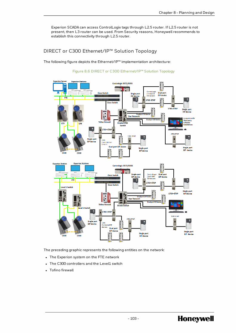
Chapter 8 - Planning and Design
Experion SCADA can access ControlLogix tags through L2.5 router. If L2.5 router is notpresent, then L3 router can be used. From Security reasons, Honeywell recommends toestablish this connectivity through L2.5 router.
DIRECT or C300 Ethernet/IP™ Solution Topology
The following figure depicts the Ethernet/IP™ implementation architecture:
Figure 8.6 DIRECT or C300 Ethernet/IP™ Solution Topology
The preceding graphic represents the following entities on the network:
l The Experion system on the FTE network
l The C300 controllers and the Level1 switch
l Tofino firewall
- 103 -

l Stratix switch
l The Ethernet/IP™ I/O devices on an Ethernet/IP™ network
l The ControlLogix PLC on an Ethernet/IP™ network
l Computer to install third-party tools
The following components on the Ethernet/IP™ network help in the integration of C300 with theEthernet/IP™-compatible I/O devices and the integration of C300 with the ControlLogix PLC:
l Level 2 CISCO switches - The level 2 CISCO switches provide a connectivity medium for C300and the Ethernet/IP™-compatible I/O devices on the Ethernet/IP™ network.
Figure 8.7 Level 2 CISCO Switch in Ethernet/IP™ Network
The Ethernet/IP™ network must be connected to the yellow CISCO switch. The components areconnected as follows, as shown in the figure:
o C300 controllers are connected to CF9
o The CF9 devices are connected to the CISCO switches on level 2
o Additionally, the connections from the Ethernet/IP™-compatible I/O devicesconnected to the Stratix switch converge to the CISCO switch through the Tofinofirewall.
For more information about configuring the Level 2 CISCO switches, see FaultTolerant Ethernet Overview and Implementation Guide.
l Tofino firewall - The Tofino firewall is used as a security solution to ensure a securecommunication on the network. The Tofino security appliance is added to allow only theEthernet/IP™ traffic to and from the L2 Switches. You can define firewall rules, specify thedevices that are allowed to communicate, and specify the protocols that can be used. TheTofino firewall is connected to the Stratix switch. For more information about Tofino firewallconfiguration, see Tofino Configuration overview
l Stratix switch - A Stratix switch is used for connecting the Ethernet/IP™-compatible I/O devices
- 104 -
Chapter 8 - Planning and Design

Chapter 8 - Planning and Design
and the ControlLogix PLC to the C300 controllers. It connects to the C300 through the level 2CISCO switches. The following components are connected to the Stratix switch:
Figure 8.8 Stratix Switch in Ethernet/IP™ Network
o The I/O devices, drives, and relays
o The ControlLogix PLC
o Computer in which third-party tools are installed
For more information about the Stratix switch configuration, see Configuring the Stratix switch.
l Ring Supervisor - The Ring supervisor is a part of the Ethernet/IP™ devices. The Ringsupervisor connects to the Stratix switch. If a Stratix 8000 is used, then the Ring Supervisorresides in a separate device, typically an ETAP, and connects to the siwtch. If a Stratix 5700 isused, then the switch may be connected directly to the DLR ring.
Figure 8.9 Ring Supervisor in Ethernet/IP™ Network
- 105 -
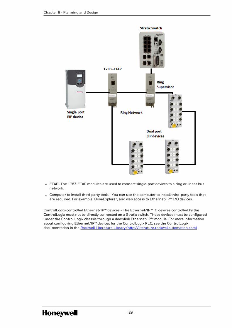
l ETAP- The 1783-ETAP modules are used to connect single-port devices to a ring or linear busnetwork.
l Computer to install third-party tools - You can use the computer to install third-party tools thatare required. For example: DriveExplorer, and web access to Ethernet/IP™ I/O devices.
ControlLogix-controlled Ethernet/IP™ devices - The Ethernet/IP™ IO devices controlled by theControlLogix must not be directly connected on a Stratix switch. These devices must be configuredunder the Control Logix chassis through a downlink Ethernet/IP™ module. For more informationabout configuring Ethernet/IP™ devices for the ControlLogix PLC, see the ControlLogixdocumentation in the Rockwell Literature Library (http://literature.rockwellautomation.com) .
- 106 -
Chapter 8 - Planning and Design

ETHERNET/IP™ DEVICE CONFIGURATION IN CEE
The C300 controller or UOC supports communication with Ethernet/IP™-compliant third-partydevices, such as I/Os, drives, and relays. To facilitate the integration of C300 or UOC with theEthernet/IP™-compliant devices, you must configure equivalent device blocks by using theControl Builder. Each configured device block represents an equivalent physical Ethernet/IP™-compliant-device, which is installed on the Ethernet/IP™ network.
Configuring an Ethernet/IP™ device includes the following tasks:
1. Configuring an Ethernet/IP™ device block in Control Builder.
For more information, see the following topics:
l Configuring the ArmorPoint Ethernet/IP™ adapter
l Configuring ArmorPoint and ArmorBlock I/O module blocks
l Configuring PowerFlex drive blocks
l Configuring E3 relay blocks
2. Assigning the configured Ethernet/IP™ device block to the CEEC300 block.
The following table lists the supported Ethernet/IP™-compliant devices:
- 107 -
CHAPTER
9

Device Supported catalog/model number
Ethernet/IP™ adapter ArmorPoint 1738-AENT adapter
ArmorPoint I/O module l ArmorPoint 1738-IB4DM12
l ArmorPoint 1738-IB8M12
l ArmorPoint 1738-IE2CM12
l ArmorPoint 1738-IE4CM12
l ArmorPoint 1738-IR2M12
l ArmorPoint 1738-IT2IM12
l ArmorPoint-1738-OA2M12AC3
l ArmorPoint 1738-OB2EPM12
l ArmorPoint 1738-OB8EM12
l ArmorPoint 1738-OE2CM12
l ArmorPoint 1738-OE4CM12
ArmorBlock I/O module l ArmorBlock 1732E-IB16M12DR
l ArmorBlock 1732E-IF4M12R
l ArmorBlock 1732E-IR4IM12R
l ArmorBlock 1732E-IT4IM12R
l ArmorBlock 1732E-OF4M12R
PowerFlex Drives PowerFlex drive 755
Adapter for Relays 193-DNENCATR adapter
Relays l E3
l E3 plus
For more information about the devices in the preceding table, see the Rockwell Literature Library.
NOTE
You can also add and configure other Ethernet/IP™-compliant devices and modules.However, these devices and modules will be created, validated, and integrated by Honeywellrepresentatives. The File > New > Type > Ethernet/IP™ Device is used for adding andconfiguring these devices. Therefore, for more information about adding devices andmodules that are not listed in the preceding table, contact your Honeywell representative.
9.1 Guidelines for Ethernet/IP™ device configuration
This section provides some general guidelines for Ethernet/IP™ device configuration.
- 108 -
Chapter 9 - Ethernet/IP™ Device Configuration in CEE

Chapter 9 - Ethernet/IP™ Device Configuration in CEE
9.1.1 Ethernet/IP™ device configuration guidelines
Device Guideline
E3/E3 plusrelays
In the following scenarios, E3 and E3 plus relays do notcommunicate with the C300 or UOC . If the C300 or UOC has E3or E3 plus IO configured and loaded in the C300 or UOC, thecheckpoint restore operation will not restore the connection tothese IO’s. To ensure that E3 and E3 plus relays communicatewith C300 or UOC, power cycle the 193-DNENCATR adapter.
l Scenario 1
1. Restart the C300 or UOC without battery power.
2. Perform a checkpoint restore.
E3 and E3 plus relays are unable to communicate with C300or UOC.
l Scenario 2
1. Perform a Switchover of C300 or UOC.
2. Disconnect the E3 network cable.
3. Delete the E3 relay from the monitoring side.
4. Connect the E3 network cable.
5. Load the E3 relay.
E3 is unable to communicate with the C300 or UOC.
In the following scenarios, ensure that you delete the loaded E3and E3 plus relays from the monitoring side before performingthe required tasks. Deleting the loaded relay devices ensures thatthe connections to the E3 and E3 plus are not affected when youuse a checkpoint restore.
l Scenario 1 — Replacing non-redundant C300 modules orUOC, where the C300 modules or UOC have E3 or E3 plusconfigured and loaded
l Scenario 2 — Upgrading C300 or UOC with a new firmwarein an off-process upgrade process, where the C300 moduleshave E3 or E3 plus configured and loaded
However, if you do not delete the E3 and E3 plus beforeperforming the preceding tasks, and you use checkpoint restore,then you must power cycle the 193-DNENCATR adapter toensure that E3 and E3 plus relays communicate with C300 orUOC.
Applicable to E3 plus relays only
Although the starter or motor is not connected to the E3 plus
- 109 -

Device Guideline
relay, the relay might trip with a Blocked Start indication.
Workaround to recover the device from this trip condition
Configure the Starts/Hour parameter and the Starts Intervalparameters as follows:
l Configure the Starts/Hour to allow more starts per hour
l Shorten the interval between the starts in the Starts Intervalparameter
For more information about troubleshooting related to E3 plusrelay trip with a Blocked Start indication, see the E3 & E3 PlusSolid-State Overload Relay User manual from the RockwellLiterature Library.
Also to clear the fault from the Control Builder, run the E3[0]:Fault Reset command through the E3 plus output channel.
PowerFlexdrives
PowerFlex drive does not provide options to modify certainparameters while the drive is running. If you make changes tothe parameters while the PowerFlex drive is running, ensure thatyou verify whether the changes are applied by using the Driveexplorer.
Ethernet/IP™IO anddevices
For Ethernet/IP™ IO and devices, the system validates forduplicate IP address and slot. For non-chassis based IO anddevices like the ArmorPoint adapter, PowerFlex drives, and theArmorBlock IOs, when the IP address is updated, the system willtry to identify if the same IP address has been configured insome other IO or Controller within the same cluster or ERDB. Ifthe system identifies that there is another block that has thesame IP address, an error is displayed, and the new value for theIP address will not be saved.
For chassis-based IO and devices like ArmorPoint IO modules,the system validates the combination of the IP address and slot.It checks whether the combination of IP address and slot is usedor configured for any other IO or device within the samecluster/ERDB. You cannot set the value for the slot on the blockif the IP address and slot combination is in use by another blockin the same cluster/ERDB.
In ArmorBlock 1732E-OF4M12R module and ArmorPoint 1738-OE4CM12, 1738-OE2CM12 modules, when configuring theFault Action to hold Fault Value, if you enter a value, which is outof the specified range, an error is not displayed. Therefore,ensure that you to enter appropriate values within the range thatyou have specified.
- 110 -
Chapter 9 - Ethernet/IP™ Device Configuration in CEE

Chapter 9 - Ethernet/IP™ Device Configuration in CEE
Device Guideline
Ensure that the number of Ethernet/IP™ devices configured andloaded do not exceed the limit (of 70 devices), as mentioned inthe Ethernet/IP™ specifications. For more information, see theSpecifications document.
9.2 Known limitations
This section provides details about the behavior of the Ethernet/IP™ devices in various scenarios.
Scenario E3/E3 plus relays PowerFlexdrives
ArmorPointI/O devices
ArmorBlockI/O devices
Controller—related actions
C300 or UOCswitchover
During a switchover, C300 or UOC will hold the last value for amaximum of 3 seconds. During this period, it will reconnectto the Ethernet/IP™ I/O devices. If for reasons, such as third-party issues or network issues, the reconnection from the newprimary C300 controller or UOC is not completed within 3seconds, an alarm will be raised.
Checkpointrestore aftercontrollerfailure
Scenario:Failure of Non-redundant orredundantC300 modulesor UOC, whichare runningwithout batterybackup arefaulted andmust berecovered usingcheckpointrestore
E3/E3 plusdevices do notcommunicatewith C300 orUOC, until youpower cycle the193-DNENCATRadapter. Formoreinformation, seeGuidelines forEthernet/IP™deviceconfiguration
C300 or UOCwill be able toreestablishconnection.
Armor PointIO devicesmight notcommunicatewith C300 orUOC, untilyou powercycle theArmorPointIO adapter.
C300 orUOC will beable toreestablishconnection.
Disconnection of cables
Disconnectionof the cablebetween theStratix switch
E3/E3 plus relays, PowerFlex drives, ArmorPoint I/O, andArmorBlock I/O devices disconnect when the cables aredisconnected and report an alarm. The devices reconnectwhen the cables are connected.
- 111 -

Scenario E3/E3 plus relays PowerFlexdrives
ArmorPointI/O devices
ArmorBlockI/O devices
andEthernet/IP™devices
Disconnectionof the Stratixuplink cablebetween Stratixand Tofinofirewallhardwaremodule
Disconnectionof the cablebetween Tofinofirewallhardwaremodule and theL2 CISCOswitch
E3/E3 plus relays, PowerFlex drives, ArmorPoint I/O, andArmorBlock I/O devices disconnect when the cables aredisconnected and report an alarm. The devices reconnectwhen the cables are connected.
When the Ethernet cable between the Tofino firewall and theL2 switch is disconnected and reconnected, the connectionmight be lost for some time. However, the C300 controllers orUOC connecting to the Ethernet/IP™ I/O modules reconnectagain after sometime. This temporary disconnection and re-connection might result in the regeneration of thecommunication alarm of Ethernet/IP™ output IO modules.The alarm might be generated multiple times.
Switch-related actions
Power cycle theStratix switch
E3 and E3 plus relays, PowerFlex drives, ArmorPoint I/O, andArmorBlock I/O devices disconnect after a power cycle of theStratix switch. The devices reconnect after the switch isrestarted.
Power cycle ofthe Tofinofirewallhardwaremodule
E3 and E3 plus relays, PowerFlex drives, ArmorPoint I/O, andArmorBlock I/O devices disconnect after a power cycle of theTofino firewall hardware module. The devices reconnect afterthe Tofino firewall hardware module is restarted.
Power cycle ofthe yellow L2CISCO switch
E3 and E3 plus relays, PowerFlex drives, ArmorPoint I/O, andArmorBlock I/O devices disconnect after a power cycle of theyellow L2 CISCO switch. The devices reconnect after theyellow L2 CISCO switch is restarted.
Other Scenarios
Cross-overcable loop
You might experience the following issues. To resolve theissues, remove the loop and restart the devices.
- 112 -
Chapter 9 - Ethernet/IP™ Device Configuration in CEE

Chapter 9 - Ethernet/IP™ Device Configuration in CEE
Scenario E3/E3 plus relays PowerFlexdrives
ArmorPointI/O devices
ArmorBlockI/O devices
between 2 localports of theStratix switch
l E3/E3 plus relays, PowerFlex drives, ArmorPoint I/O, andArmorBlock I/O devices disconnect for a few seconds andthen reconnect.
l Sometimes, there might be continuos disconnects.
NOTE
In some I/O devices, you might observe a permanentdisconnect.
Cross-overcable loopbetween thelocal ports ofthe top-levelyellow switch
E3/E3 plus relays, PowerFlex drives, ArmorPoint I/O, andArmorBlock I/O devices disconnect.
Cross-overcable loopbetween theStratix switchand the top-level yellowCISCO switch
There might be a continuous disconnection.
Duplicate IPnodes on thenetwork
Ensure that there are no duplicate IP nodes on the network. Ifthe IP address of an already loaded Ethernet/IP™ IO isduplicated for another Ethernet/IP™ IO device, which isconnected to the Uplink port of the L2 switch, the existingEthernet/IP™ IO device loses its communication with theC300 or UOC.
BackInitialization
Backinitialization isnot supported inE3/E3 plusrelays.
Backinitialization isnot supportedin PowerFlexdrives.However, whenyou opt forsetting theComm FaultAction statusto Hold Lastvalue, then the
Backinitializationis notsupported inArmorPointdevices.
Backinitializationis notsupportedinArmorBlockdevices.
- 113 -

Scenario E3/E3 plus relays PowerFlexdrives
ArmorPointI/O devices
ArmorBlockI/O devices
re-connectionis smooth.
9.2.1 Observations
l Following are some observations with respect to ArmorBlock I/O devices:o ArmorBlock 1732E-OF4M12R only — In a linear bus network, when you disconnect
the ArmorBlock module, all the remaining ArmorBlock modules are disconnected andthe fault value is not set to the configured value (per the fault value configuration).This behavior is not observed in a star network.
Consider the following scenario:o ArmorBlock 1732E-OF4M12R module is connected in the first position or in the
middle of the linear network.
o Port 2 is connected to another ArmorBlock module.
When Port 2 is disconnected, all the remaining ArmorBlock modules aredisconnected, and additionally, there is a drop in the OP voltage. When youreconnect, the output returns to its last value.
o For ArmorBlock 1732E-IF4M12R module only — In ArmorBlock 1732E-IF4M12Rmodule, when the channels are in voltage mode, the channel status remains normaleven at open wire condition. However, during open wire condition, the channelsshow the following approximate values, depending on the voltage ranges:
NOTE
The following are the observed values. However, these values might varydepending on the environment and the nature of the activities that areperformed.
o 0 to 5V ≈ 50%
o 0 to 10V ≈ 25%
o -10 to +10V ≈ 62%
o -5 to +5V ≈ 75%
l The following observations are applicable to Armor Block I/O devices and unconsolidatedArmor Point I/O modules
o If there is a communication loss when an I/O module network cable is removed fromthe Stratix switch, the input channel blocks will hold the last value until theEthernet/IP™ connection timeout occurs. However, the output I/O module continuesto drive the output using the last value held in the Input channel block because theoutput module and its channels are healthy. In this scenario:o If the connection resumes to the Input I/O module within 10 seconds, there
might be a bump observed in the output.
o If the connection to the Input I/O module does not resume within 10 seconds,the output will go to Failsafe mode after the connection timeout to the Input I/O
- 114 -
Chapter 9 - Ethernet/IP™ Device Configuration in CEE
Chapter 9 - Ethernet/IP™ Device Configuration in CEE
module.
o The following behavior was observed during a cable fault (the yellow cable) from theC300 or UOC side, where the C300 or UOC is configured with Ethernet/IP™ I/Omodules: The output Ethernet/IP™ I/O modules recover faster than the Input I/Omodules. During this scenario, a bump might be seen in the output as Input I/Omodules will hold on to the last value for a few seconds more than the Output I/Omodules.
l Loss of communication with Ethernet/IP™ devices — When there is any break in thecommunication path to a singly-attached device, it might take up to a minute for FTE toresolve; if there is an alternative path, the connection will be restored after a minute.
If there is a yellow cable fault on the C300 or UOC, which is configured with UDT access, theUDT Reads/writes will break (Reads will hold last value and writes will not go through) for aperiod of 20 seconds, until C300 or UOC reestablishes connection with the ControlLogix fromthe green interface.
l Applicable to unconsolidated Armor Point I/O connections — If there are single cable faults(Yellow cable fault on the C300 or the Yellow CF9 or UOC), based on the load on the ArmorPoint adapter, C300 or UOC might disconnect and reconnect to the Input I/O modules. Theconnection to the output I/O modules will continue on the green network without anydisconnection.
9.3 Configuring the ArmorPoint Ethernet/IP™ adapterblock
To enable communication between the ArmorPoint I/O modules and the Ethernet/IP™ network,you must configure the ArmorPoint Ethernet/IP™ adapter, 1738-AENT. One ArmorPointEthernet/IP™ adapter supports multiple ArmorPoint I/O modules.A configured ArmorPointEthernet/IP™ adapter block represents an equivalent physical Ethernet/IP™ adapter, which isinstalled on the Ethernet/IP™ network.
9.3.1 Prerequisites
Install the ArmorPoint Ethernet/IP™ adapter.
9.3.2 To configure the ArmorPoint Ethernet/IP™ adapter block
1. Click File > New > EtherNetIP Devices > 1738-AENT - ArmorPoint 1738-AENT Adapter.
The ArmorPoint adapter configuration form appears.
2. On the Main tab, specify the details for the adapter block, which include the following:
l Tag Name — For example, 1738_AENT_1234
l IP address of the device — For example, 10.10.10.1. For more information aboutconfiguring the IP address of the adapter, see Configuring the IP address of anEthernet/IP™ device.
l Chassis Size
- 115 -

ATTENTION
An attempt to communicate with the I/O module fails if the chassis size entereddoes not match the physical configuration. Therefore, ensure that the chassissize matches the number of the physically installed I/O modules and theadapter (chassis size = number I/O modules + one for the adapter). Forexample, if the number of I/O modules is 10, the chassis size should be 11.
3. If you want to consolidate connections for a group of I/O modules, which are assigned to theadapter, under Network Configuration, select the Consolidate Connections check box.
For more information about Consolidating connections, see Consolidate connections.
4. If you select the Consolidate Connections option, type the following details for the RequestedPacket Interval (RPI). RPI specifies the rate at which data is updated during a connection. TheRPI specified is applicable for all the I/O modules associated to the adapter.
l Target –> Originator RPI (ms) — For example, 100
l Originator –>Target RPI (ms) — For example, 100
5. If the EIP IO communication is Through EIM, please select the EIM Name through with theEIP IO communication will happen.
6. Complete the required details on all the other tabs and click OK. For more information aboutthe parameters on the Main tab and the other tabs, see the Control Builder ParameterReference.
9.3.3 Results
The ArmorPoint adapter is configured and appears in the Unassigned category of the Project Tree.
9.3.4 Next steps
After creating the adapter block, you must assign it to the CEEC300 block. For more information,see Assigning Ethernet/IP™ devices to the CEE C300 block.
l Consolidate connections
l Configuring the IP address of an Ethernet/IP™ device
9.3.5 Consolidate connections
The 1738-AENT adapter provides the Assembly connection feature, which helps you inconsolidating connections for a group of ArmorPoint I/O modules.
ATTENTION
To consolidate the connections for a group of ArmorPoint I/O modules ensure that theArmorPoint I/O modules in the group are supported by the 1738-AENT adapter.
This feature ensures that a single connection is used for the group of ArmorPoint I/O modules,instead of one connection per I/O module. Consolidating the connections optimizes the usage ofnetwork bandwidth because data for all the ArmorPoint I/O modules is transferred over a singleconnection. Therefore, it reduces the number of packets on the network.
- 116 -
Chapter 9 - Ethernet/IP™ Device Configuration in CEE

Chapter 9 - Ethernet/IP™ Device Configuration in CEE
You can opt to consolidate connections for a group of ArmorPoint I/O modules while configuringthe 1738-AENT adapter block. The 1738-AENT adapter block configuration form provides options toenable this feature. To enable the Assembly connection feature, select the Consolidateconnections check box on the adapter block configuration form.
If you select this option, you must also provide the Requested Packet Interval (RPI) details. RPI isused to indicate the rate at which the data is updated when connected. The RPI details will beapplicable for all the ArmorPoint I/O modules, which are assigned to the adapter.
Ensure that the RPI value is a multiple of the base cycle of the controller. If the RPI value is not amultiple of the base cycle of the controller, a value clamped warning appears during loading.
ATTENTION
When you change any configuration settings to the ArmorPoint I/O modules, which are apart of the consolidated connections, the changes are not reflected. To ensure that thechanges are reflected, reload the ArmorPoint 1738-AENT adapter.
For more information about configuring consolidating connections on the ArmorPoint adapterconfiguration form, see Configuring an ArmorPoint Ethernet/IP™ adapter block.
9.3.6 Configuring the IP address of an Ethernet/IP™ device
A default IP address is provided by the vendor, for every Ethernet/IP™ device. You can access theNetwork Configuration page of the device to configure the IP address based on the networksettings at your location.
ATTENTION
This topic outlines the procedure for configuring the IP address for an ArmorPoint adapter.For a detailed procedure about configuring the IP address for the ArmorPoint adapter andother Ethernet/IP™ devices provided by Rockwell, see the documentation at RockwellLiterature Library.
Prerequisites
l The default IP address of the device
l Web browser
To configure the I/P address of the adapter
1. From a web browser, access the Network Configuration page by using the default IP address.
2. On the Network Configuration page, specify the required IP address and all the requireddetails, which are relevant to the network settings, at your location.
Results
The IP address of the device is configured.
- 117 -

9.4 Configuring ArmorPoint I/O module blocks
A configured I/O module block represents an equivalent physical I/O module, which is installed onthe Ethernet/IP™ network. Refer to the following procedure to configure all the supportedArmorPoint I/O module blocks. For more information about the supported I/O modules, seeEthernet/IP™ device configuration.
9.4.1 Prerequisites
l Install the ArmorPoint I/O devices.
l Ensure that you have configured an ArmorPoint adapter block. For more information aboutconfiguring an ArmorPoint adapter block, see Configuring the ArmorPoint Ethernet/IP™adapter block.
9.4.2 To configure an ArmorPoint I/O module block
1. Click File > New > EtherNetIP Devices > ARMOR_POINT_IO > <Device>.
Device represents the ArmorPoint I/O device that you want to configure.
ATTENTION
You can also create an instance of the device by using a template from the library.
The I/O module block configuration form appears.
2. On the Main tab, specify the required details, which include the following:
l Tag name — For example, 1738_IB4DM12_1234
l Item Name — For example, ArmorPoint_1738-IB4DM12_1234
l Specify the Requested Packet Interval (RPI) values. RPI specifies the rate at which data isupdated when connected.
ATTENTION
If the RPI value does not adhere to the following, then the value will berounded down to the nearest base cycle and while loading, a warning will bedisplayed:
o Ensure that the RPI value is a multiple of the base cycle of thecontroller and in multiples of 50.
o Ensure that you enter a value in the following range for ArmorPointI/O modules — 50 ms and 2000 ms
o Target –> Originator RPI (ms) — For example, 100 mso Originator –>Target RPI (ms) — For example, 100 ms
- 118 -
Chapter 9 - Ethernet/IP™ Device Configuration in CEE

Chapter 9 - Ethernet/IP™ Device Configuration in CEE
ATTENTION
If you have specified the RPI details while consolidating connections in theArmorPoint adapter block, the RPI details for the ArmorPoint I/O device are auto-populated in the ArmorPoint I/O module block configuration form. For moreinformation about Consolidating connections in the ArmorPoint adapter, seeConsolidate Connections. Consolidating connections is supported only forArmorPoint I/O modules.
3. Complete the required details on all the other tabs and click OK.
For more information about the other tabs, see:
l Channel Configuration tab
l Alarms tab
l C300 Controller User's Guide
l UOC User's Guide
ATTENTION
In the Data/Status tab of the configuration form, the row numbers of the grid startfrom 0. The row numbers do not indicate the channel number. It indicates that therow number of the grid starts from 0.
In ArmorPoint output modules, when there is a channel fault, an alarm or event isnot generated by default. However, you can configure to generate an alarm byusing a flag block.
For more information about the parameters on all the tabs, see the Control Builder ParameterReference.
ATTENTION
The ArmorPoint adapter must be loaded before loading the ArmoroPoint I/Omodules.
9.4.3 Results
The I/O block is configured and appears in the Unassigned category of the Project Tree.
9.4.4 Next steps
After configuring the I/O block, assign it to the Ethernet/IP™ adapter block
For more information, see Assigning Ethernet/IP™ devices to the CEE C300 block.
9.5 Configuring ArmorBlock I/O module blocks
A configured I/O module block represents an equivalent physical I/O module, which is installed onthe Ethernet/IP™ network. Refer to the following procedure to configure all the supportedArmorBlock I/O module blocks. For more information about the supported I/O modules, seeEthernet/IP™ device configuration.
- 119 -

9.5.1 Prerequisites
Install the ArmorBlock I/O device.
9.5.2 To configure an ArmorBlock I/O module block
1. Click File > New > EtherNetIP Devices > ARMOR_BLOCK_IO > <Device>.
Device represents the ArmorBlock I/O device that you want to configure.
ATTENTION
You can also create an instance of the device by using a template from the library.
The I/O module block configuration form appears.
2. On the Main tab, specify the required details, which include the following:
l Tag name — For example, 1732E_IB16M_1234
l Item Name — For example, Armorblock_IB16M_1234
l IP address of the device — Type the required IP address of the device. For example,10.10.10.1. For more information about configuring the IP address of the adapter, seeConfiguring the IP address of an Ethernet/IP™ device
l Specify the Requested Packet Interval (RPI) values. RPI specifies the rate at which data isupdated when connected.
ATTENTION
If the RPI value does not adhere to the following, then the value will berounded down to the nearest base cycle and while loading a warning will bedisplayed:
o Ensure that the RPI value is a multiple of the base cycle of thecontroller and in multiples of 50.
o Ensure that you enter a value in the following range for ArmorBlockI/O modules — 50 ms and 750 ms
o Target –> Originator RPI (ms) — For example, 100 mso Originator –>Target RPI (ms) — For example, 100 ms
o For ArmorBlock 1732E-IF4M12, the Originator –>Target RPI value must be500ms or 750 ms.
o For ArmorBlock 1732E-IT4IM1, the Originator –>Target RPI value must be500ms or 750 ms.
3. If the EIP IO communication is Through EIM, please select the EIM Name through with theEIP IO communication will happen.
4. Complete the required details on all the other tabs and click OK.
For more information about the other tabs, see:
l Channel Configuration tab
l Alarms tab
l C300 Controller User's Guide
l UOC User's Guide
- 120 -
Chapter 9 - Ethernet/IP™ Device Configuration in CEE

Chapter 9 - Ethernet/IP™ Device Configuration in CEE
ATTENTION
In the Data/Status tab of the configuration form, the row numbers of the grid startfrom 0. The row numbers do not indicate the channel number. It indicates that therow number of the grid starts from 0.
In ArmorBlock output modules, when there is a channel fault, an alarm or event isnot generated by default. However, you can configure to generate an alarm byusing a flag block.
For more information about the parameters on all the tabs, see the Control Builder ParameterReference.
9.5.3 Results
The I/O block is configured and appears in the Unassigned category of the Project Tree.
9.5.4 Next steps
After configuring the I/O block, assign it to the CEE C300 block.
For more information, see Assigning Ethernet/IP™ devices to the CEE C300 block.
9.6 Configuring the EIP GenAdapter Block
To enable communication with I/O Modules connected through a Generic Adaptor device, youmust configure the GenAdapter EIP adapter block. One EIP GenAdapter supports multipleEthernet I/O modules. A configured EIP GenAdapter block represents a physical EIP adapter,which is installed on the EIP network.
To configure the EIP GenAdapter block
1. Click File > New > Ethernet IP Devices > GenAdapter-EIP Generic Adapter.
- 121 -
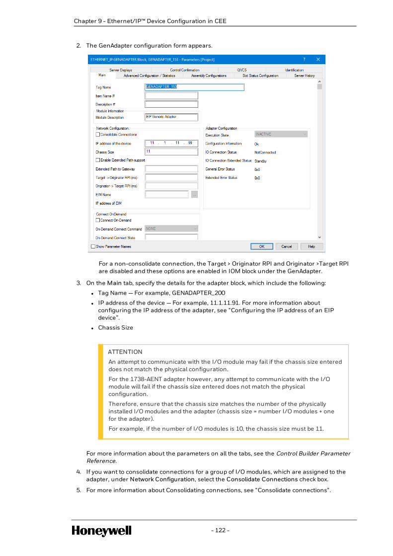
2. The GenAdapter configuration form appears.
For a non-consolidate connection, the Target > Originator RPI and Originator >Target RPIare disabled and these options are enabled in IOM block under the GenAdapter.
3. On the Main tab, specify the details for the adapter block, which include the following:
l Tag Name — For example, GENADAPTER_200
l IP address of the device — For example, 11.1.11.91. For more information aboutconfiguring the IP address of the adapter, see “Configuring the IP address of an EIPdevice”.
l Chassis Size
ATTENTION
An attempt to communicate with the I/O module may fail if the chassis size entereddoes not match the physical configuration.
For the 1738-AENT adapter however, any attempt to communicate with the I/Omodule will fail if the chassis size entered does not match the physicalconfiguration.
Therefore, ensure that the chassis size matches the number of the physicallyinstalled I/O modules and the adapter (chassis size = number I/O modules + onefor the adapter).
For example, if the number of I/O modules is 10, the chassis size must be 11.
For more information about the parameters on all the tabs, see the Control Builder ParameterReference.
4. If you want to consolidate connections for a group of I/O modules, which are assigned to theadapter, under Network Configuration, select the Consolidate Connections check box.
5. For more information about Consolidating connections, see “Consolidate connections”.
- 122 -
Chapter 9 - Ethernet/IP™ Device Configuration in CEE

Chapter 9 - Ethernet/IP™ Device Configuration in CEE
6. If you select the Consolidate Connections option, type the following details for the RequestedPacket Interval (RPI). RPI specifies the rate at which data is updated during a connection. TheRPI specified is applicable for all the I/O modules associated to the adapter.
l Target > Originator RPI (ms) — For example, 100
l Originator >Target RPI (ms) — For example, 100
7. The EIM Name is specified when the adaptor block is used in a C300 to EIM configuration.When used in a UOC configuration, it is left blank.
8. Complete the required details on all the other tabs and click OK. For more information aboutthe parameters on the Main tab and the other tabs, see Control Builder Parameter Reference.
9.6.1 Results
The GenAdapter is configured and appears in the Unassigned category of the Project Tree.
9.6.2 Next steps
After creating the adapter block, you must assign it to the CEE.
For more information, see Assigning EIP GenAdapter to the CEE UOC block.
Consolidate connections
The GenAdapter provides the Consolidate Connections feature, which is also referred to asAssembly Connections, Rack Connections, or Gateway Connections.
This feature consolidates connections for a set of I/O Modules and releases a single connectioninstead of creating one connection per I/O Module. The data for all I/O Modules participating in aConsolidate Connection is communicated on a single connection which reduces the number ofpackets on the network, and hence optimizes the usage of network bandwidth.
You can enable this feature using the GenAdapter block configuration form.
- 123 -

ATTENTIONTo consolidate the connections for a group of I/O modules ensure that the I/O modules inthe group are supported by the GenAdapter.
To enable the Assembly connection feature, select the Consolidate Connections check box on theadapter block configuration form. If you select this option, also provide the Requested PacketInterval (RPI) details. RPI is used to indicate the rate at which the data is updated when connected.The RPI details will be applicable for all the I/O modules, which are assigned to the adapter.Ensure that the RPI value is a multiple of the base cycle of the controller. If that is not the case, awarning message informing you that the value is clamped appears during loading.
Assembly Configuration for Consolidate Connection
An Assembly Configuration consists of Connection Parameters and the Slot Assembly Map.Connection Parameters consists of the Assembly Instance Number and the Size (Bytes) of Config,Input and Output Assemblies. The Slot Assembly Map consists of data byte, bit offsets and bit sizesof Input and Output Assembly data produced and consumed by the EIP Adapter. AssemblyConfiguration values for a specific family of EIP adapter will be provided in the User Manual of theAdapter. Project Engineers must update the values carefully after reading the User Manual.
To configure the assembly configuration for the consolidated connection, follow these steps:
1. After you have configured the consolidated connection to the EIP GenAdapter, select theAssembly Configurations tab.
NOTE The EIP GenAdapter supports only zero configuration size for consolidateconnection.
- 124 -
Chapter 9 - Ethernet/IP™ Device Configuration in CEE

Chapter 9 - Ethernet/IP™ Device Configuration in CEE
2. Enter information in the Assembly Configuration details as listed below.
Field Description
Connection Parameters
Assembly Description By default, the Config, Input andOutput are displayed.
Assembly Instance Number Enter the instance number providedby the vendor manual or from EDS(electronic data sheet) file.
Assembly Instance Size (Bytes) Enter the instance size provided bythe vendor manual or from EDS(electronic data sheet) file.
Run Idle Enter the run idle details provided by thevendor.
Slot Assembly Map This section allows you to send data to or receive data from the fielddevices. This section describes mapping data to various I/O modules. For moreinformation on mapping, see the vendor’s manual or the EDS file.
Byte offset (input) Enter the byte offset for input of I/Omodule.
Bit offset (input) Enter the bit offset for input of I/O module.
Bit size (input) Enter the bit size for input of I/O module.
Byte offset output Enter the byte offset for output of I/Omodule.
Bit offset output Enter the bit offset for output of I/Omodule.
Slot Status Configuration for Consolidate Connection
The Slot Status Configuration values of a GenAdapter block represents the per slot status headerproduced by EIP Adapter to represent the device/IOM removal and reinsertion from and to chassis,when consolidate connection is active. This configurable feature is based on the user’s selection.The Project Engineer enters values for configuration parameters and clicks OK. The Systempresents the Ethernet Adapter instance in the Project side under Un-assigned node.
To configure the slot status configuration for the consolidated connection:
1. After configuring the consolidated connection to the EIP GenAdapter, click the Slot StatusConfigurations tab.
- 125 -

2. Enter information in the Slot Status configuration details as listed below. Every parameter onthis table helps you program how to determine communication failure with a module in thechassis when participating in an assembly/gateway or adaptor connection
Field DescriptionEnable SlotStatusProcessing
Select this to enable the slot status processing
Data type Select the data type of the slot status as defined by thevendor manual
Slot Status Assembly Map
Enables you to map, on a per slot basis, where in the input assembly toobtain the communication fail status information from.
Byte offset Enter the byte offset of input for I/O module.
Bit offset Enter the bit offset of input for I/O module
Good value Enter the good value for the specific slot.
Current value Is the value per the defined data type picked from the specified Byteand Bit offsets. It is then compared with the good value anddepending upon the comparison (equal or unequal), the IOM in aslot is informed whether or not it faces a diagnostic – which in thiscase is communication failure.
Advanced Configuration/ Statistics for Consolidate Connection
- 126 -
Chapter 9 - Ethernet/IP™ Device Configuration in CEE

Chapter 9 - Ethernet/IP™ Device Configuration in CEE
Few additional Network configuration parameters have been added to let the user Configure someAdvanced Network related parameters. These parameters appear in a separate tab on the form ofEIP devices.
Enter information in the Advanced Configuration/ Statistics details as listed below.
Field Description
OTConnectionType
Select the Range for OT Connection Type as defined. Theparameter represent Connection type as defined in CIP.
TOConnectionType
Select the Range for TO Connection Type as defined. Theparameter represent Connection type as defined in CIP.
OTConnectionPriority
Select the Range for OT Connection Priority as defined.
TOConnectionPriority
Select the Range for TO Connection Priority as defined.
Status/Statistics
Shows the status of General Error and Extended Error StatusNumber.
- 127 -

9.7 Configuring the IP address of an EIP device
A default IP address is provided by the vendor, for every EIP device. You can access the NetworkConfiguration page of the device to configure the IP address based on the network settings at yourlocation.
Prerequisites
l The default IP address of the device
l Web browser
l Using Bootp application
To configure the I/P address of the adapter
1. From a web browser, access the Network Configuration page using the default IP address.
2. On the Network Configuration page, specify the required IP address and all the requireddetails relevant to the network settings at your location.
3. Using the Bootp software configure the IP address.
Results
The IP address of the device is configured.
9.8 Configuring GenAdapter I/O module blocks
A configured I/O module block represents a physical I/O module, which is installed on the EIPnetwork. Use the following procedure to configure all the supported I/O module blocks.
Prerequisites
l Install the GenAdapter I/O device.
To configure an GenAdapter I/O module block
1. Click File > New > Ethernet IP Devices > <Library Name > <Device>.
2. Device represents the I/O device that you want to configure.
NOTE
You can also create an instance of the device by using a template from the library.
3. On the Main tab, specify the required details, which include the following:
l Tag name — For example, 1738E_IB16M_1234
l Item Name — For example, Armorpoint_IB16M_1234
l IP address of the device — Type the required IP address of the device. For example,10.10.10.1.
ATTENTION
- 128 -
Chapter 9 - Ethernet/IP™ Device Configuration in CEE

Chapter 9 - Ethernet/IP™ Device Configuration in CEE
If you select the Enable Extended Path Support, the Extended Path to Gatewayoption is enabled.
For more information on EIP Device addressing modes see Device addressingmodes.
4. For more information about configuring the IP address of the adapter, see Configuring the IPaddress of an EIP device.
5. Specify the Requested Packet Interval (RPI) values. RPI specifies the rate at which data isupdated when connected.
ATTENTION
If the RPI value does not adhere to the following, then the value will be roundeddown to the nearest base cycle and this warning will be displayed while loading:
l Ensure that the RPI value is a multiple of the base cycle of the controller and inmultiples of 50.
l Ensure that you enter a value in the following range for ArmorBlock I/Omodules — 50 ms and 750 ms.
l Target > Originator RPI (ms) — For example, 100 ms
l Originator >Target RPI (ms) — For example, 100 ms
NOTE
l For ArmorBlock 1732E-IF4M12, the Originator >Target RPI value must be 500ms or 750 ms.
l For ArmorBlock 1732E-IT4IM1, the Originator >Target RPI value must be 500ms or 750 ms.
6. If the EIP I/O communication is through EIM, select the EIM Name through which the EIP I/Ocommunication will happen.
7. Complete the required details on all the other tabs and click OK. For more information aboutthe other tabs, see the “Channel Configuration tab” and “Alarms tab” sections in the ControlBuilding User’s Guide.
NOTE
In the Data/Status tab of the configuration form, the row number of the grid startsfrom 0. The row number does not indicate the channel number. It indicates that therow number of the grid starts from 0.
In ArmorBlock output modules, when there is a channel fault, an alarm or event isnot generated by default.
However, you can configure to generate an alarm by using a flag block.
For more information about the parameters on all the tabs, see Control Builder ParameterReference.
Results
The I/O block is configured and appears in the Unassigned category of the Project Tree.
- 129 -

Next steps
After configuring the I/O block, assign it to the CEE UOC block.
9.9 Slot 0 Diagnostic Information
To retrieve diagnostic information from slot 0 of an adaptor device which supports Class 1 EIPconnections, Application Engineers can attach a generic device to slot 0.
- 130 -
Chapter 9 - Ethernet/IP™ Device Configuration in CEE

Chapter 9 - Ethernet/IP™ Device Configuration in CEE
9.10 Slot 0 Configuration
1. Add the Chassis Size for the adapter under the generic adapter configuration form.
2. Add device/IOM under Generic Adapter or 1738-AENT adapter.
- 131 -

3. Provide the slot number of device or IOM as 0 to allot the generic device to slot 0.
9.11 Configuring PowerFlex drive blocks
A configured PowerFlex drive block represents an equivalent physical drive, which is installed onthe Ethernet/IP™ network.
CAUTION
The drive and the relay (E3 and E3 plus) module configurations are editable. These moduleshave options to edit and configure data link parameters. However, it is recommended not toedit the configurations because it might lead to undesirable results. Therefore, if you wantto configure data link parameters per your requirement, contact your Honeywellrepresentative.
9.11.1 Prerequisites
Install the PowerFlex drive.
9.11.2 To configure a PowerFlex 755 Drive block
1. Click File > New > EtherNetIP Devices > EIP_DRIVE > PF755 - PowerFlex 755 Drive.
The drive block configuration form appears.
NOTE
You can also create an instance of the drive by using a template from the library.
- 132 -
Chapter 9 - Ethernet/IP™ Device Configuration in CEE

Chapter 9 - Ethernet/IP™ Device Configuration in CEE
2. On the Main tab, specify the required details, which include the following:
l Tag name — For example, PF755_1234
l Item Name— For example, PowerFlex1234
l Engineering Units
l IP address of the device — For example, 10.10.10.1. For more information aboutconfiguring the IP address of the device, see Configuring the IP address of anEthernet/IP™ device.
l Specify the Requested Packet Interval (RPI) values. RPI specifies the rate at which data isupdated during a connection.
ATTENTION
Ensure that the RPI value is a multiple of the base cycle of the controller. Itshould be in multiples of 50 and within the following range, 50 ms and 2000ms.
o Target –> Originator RPI (ms) — For example, 100 mso Originator –>Target RPI (ms)— For example, 100 ms
3. If the Ethernet/IP™ IO communication is Through EIM, please select the EIM Name throughwith the EIP IO communication will happen.
4. Complete the required details on all the other tabs and click OK.
For more information about the other tabs, see the C300 Controller User’s guide.
For more information about the other tabs, see the UOC User’s guide.
For more information about the parameters, see the Control Builder Parameter Reference.
For more information about the other tabs, also see Ethernet/IP™ device configurationreferences.
NOTE
To configure Powerflex 753 Drive refer tohttps://www.honeywellprocess.com/library/support/software-downloads/Customer/Experion-PKS-EthernetIP-PowerFlex-753-Drive.zip.
9.11.3 Results
The PowerFlex Drive is configured and appears in the Unassigned category of the Project Tree.
9.11.4 Next steps
After creating the PowerFlex drive block, assign it to the CEEC300 block. For more information, seeAssigning Ethernet/IP™ devices to the CEE C300 block.
9.12 Configuring E3 relay blocks
A configured E3 relay block represents an equivalent physical E3/E3 plus relay, which is installedon the Ethernet/IP™ network.
- 133 -

CAUTION
The drive and the relay (E3 and E3 plus) module configurations are editable. These moduleshave options to edit and configure data link parameters. However, it is recommended not toedit the configurations because it might lead to undesirable results. Therefore, if you wantto configure data link parameters per your requirement, contact your Honeywellrepresentative.
9.12.1 Prerequisites
l Install the 193-DNENCATR adapter. This adapter is required to facilitate the Ethernet/IP™communication between the E3/E3 plus relay and the Ethernet/IP™ network.
l Install the E3/E3 plus relay.
9.12.2 To configure an E3 relay block
1. Click File > New > EtherNetIP Devices > > <EIP_Relay>Relay.
Relay represents the E3/E3 plus relay model number, which you want to configure.
For more information about the supported Relays, see Ethernet/IP™ device configuration.
ATTENTION
You can also create an instance of the relay by using a template from the library.
The relay block configuration form appears.
2. On the Main tab, specify the required details, which include the following:
l Tag name— For example, 193_DENE_E3_1234
l Item Name— For example, E3relay_1234
l Engineering Units
l IP address of the device— For example, 10.10.10.1. For more information aboutconfiguring the IP address of the device, see Configuring the IP address of anEthernet/IP™ device.
l Specify the Requested Packet Interval (RPI) values. RPI specifies the rate at which data isupdated when connected.
ATTENTION
Ensure that the RPI value is a multiple of the base cycle of the controller. Itshould be in multiples of 50 and within the following range, 50 ms and 2000ms
o Target –> Originator RPI (ms)— For example, 100 mso Originator –>Target RPI (ms)— For example, 100 ms
3. If the EIP IO communication is Through EIM, please select the EIM Name through with theEIP IO communication will happen.
4. On the Configuration tab, type the required details for Update rate for Data Link.
5. Complete the required details on all the other tabs and click OK.
For more information about the other tabs, see:
- 134 -
Chapter 9 - Ethernet/IP™ Device Configuration in CEE

Chapter 9 - Ethernet/IP™ Device Configuration in CEE
l Alarms tab
l C300 Controller User’s guide
l UOC User’s guide
For more information about the parameters on all the tabs, see the Control Builder ParameterReference.
For more information about the other tabs, also see Ethernet/IP™ device configurationreferences.
9.12.3 Results
The E3 relay is configured and appears in the Unassigned category of the Project Tree.
9.12.4 Next steps
After creating the relay block, assign it to the CEE C300 block. For more information, refer toAssigning Ethernet/IP™ devices to the CEE C300 block.
9.13 Assigning Ethernet/IP™ devices to the CEE C300block
After you configure an Ethernet/IP™ device block you must assign the blocks to the CEE C300block. However, devices which require an Ethernet/IP™ adapter must be assigned to the EtherNetadapter block, which is under the EIP DEVICES category of the CEE C300 block.
9.13.1 Prerequisites
l Configure the Ethernet/IP™ device. For more information, refer to the following topics:o Configuring the ArmorPoint Ethernet/IP™ adapter block
o Configuring ArmorPoint and ArmorBlock I/O module blocks
o Configuring PowerFlex Drive blocks
o Configuring the E3 relay blocks
9.13.2 To assign the Ethernet/IP™ devices to the CEE C300 blockDrag the configured Ethernet/IP™ devices from the Unassigned category to the CEE C300 block,under C300.
NOTE
You can optionally use the SmartBuilder to bulk assign the Ethernet/IP™devices and I/Omodules to the CEE C300 block. For more information, see the Bulk Configuration Tool Help.
A new category, EIP DEVICES, appears under the CEE C300 block. This category lists theconfigured Ethernet/IP™ devices.
9.13.3 To assign the ArmorPoint I/O devices to the adapter blockDrag the configured ArmorPoint I/O module block from the Unassigned category to the Ethernet/IP™adapter block, under EIP DEVICES.
- 135 -

NOTE
You can optionally use the SmartBuilder to bulk assign the Ethernet/IP™devices and I/Omodules to the CEE C300 block. For more information, see the Bulk Configuration Tool Help.
The I/O module block appears under the Ethernet/IP™ adapter.
9.13.4 Results
l The configured Ethernet/IP™ devices are assigned to the EIP DEVICES category under theCEE C300 block.
l The ArmorPoint I/O device blocks are assigned to the adapter blocks under the EIP DEVICEScategory.
9.14 Configuring channels in Ethernet/IP™ devices
To assign the channels from Ethernet/IP™ I/O modules to a Control Module (CM), drag therequired channels from the library or from the Project side to the CM instances. For detailedprocedures about the creation of control modules, the assignment of channels, and theunassignment of channels, see:
l Creating and saving a control module
l Associating I/O Channels to I/O Modules (IOMs)
It is mandatory for the Ethernet I/P module and the CM containing the channel of the EthernetI/P module to be assigned to the same controller. However, it is possible to assign the channel ofan Ethernet I/P module to a CM that is assigned to a different controller. For example, you canassign analog input channels that belong to an Armor Point IO module to a CM, which is under adifferent controller. But, when you try to load the CM that was assigned to a different controller, anerror is displayed and the load operation of the CM fails.
9.15 Ethernet/IP™ device configuration references
The following topics provide referential information about the various configuration tabs andparameters. For detailed information about the parameters, see the Control Builder ParameterReference.
l Alarms tab
l Channel Configuration tab
l Configuration tab
l Data/Status tab and Data/Command tab in PowerFlex drive block
l Data/Status tab and Data/Command tab in E3/E3 plus relay blocks
l Sensor Type and PV Low and High Signal range for RTD module - Armor Block 1732E-IR4IM12R
l Sensor Type and PV Low and High Signal range for Thermocouple module - Armor Block
- 136 -
Chapter 9 - Ethernet/IP™ Device Configuration in CEE

Chapter 9 - Ethernet/IP™ Device Configuration in CEE
1732E-IT4IM12R
l Cold junction configuration for thermocouple module - Armor Block 1732E-IT4IM12R
l Digital Filter configuration for thermocouple and RTD modules of the Armor block family
l PV scaling factor configuration in thermocouple modules
9.15.1 Advance Configuration or Statistics
The following table lists the various parameters on the Advance Configuration / Statistics tab. Formore information about the parameters, see the Control Builder Parameter Reference.
Advance Configuration / Statistics tab parameters
l OT Connection Type
o NULL
o MULTICAST
o POINT2POINT
l TO Connection Type
o NULL
o MULTICAST
o POINT2POINT
l OT Connection Priority
o Low Priority
o High Priority
o Scheduled
o Urgent
l TO Connection Priority
o Low Priority
o High Priority
o Scheduled
o Urgent
l Connection Timeout Multiplier
o Computed
l Vendor ID (VENDORID)
l Vendor Name (VENDORNAME)
l Product Type String (PRODTYPESTR)
l Product Name (PRODNAME)
l Product Type (PRODTYPE)
l Product Code (PRODCODE)
- 137 -

l Major Revision (MAJREV)
l Minor Revision (MINREV)
l CatLog Name (CATLOGNO)
l EDS Revision Number (REVISION)
9.15.2 Alarms tab
The following table lists the various parameters on the Alarms tab. For more information about theparameters, see the Control Builder Parameter Reference.
Alarms tab parameters
Module name Parameter description and parametername
l ArmorBlock 1732E-IB16M12DR, 16channels
l ArmorBlock 1732E-IF4M12R, 4channels
l ArmorBlock 1732E-IR4IM12R, 4channels
l ArmorBlock 1732E-IT4IM12R, 4channels
l ArmorPoint 1738-IB4DM12, 4channels
l ArmorPoint 1738-IE2CM12, 2channels
l ArmorPoint 1738-IE4CM12, 4channels
l ArmorPoint 1738-IR2M12, 2channels
l ArmorPoint 1738-IT2IM12, 2channels
l PowerFlex drive
l E3 plus
l Alarm (ALMSTR)
l Priority (ALMPRI)
l Severity (ALMSEV)
l Description (ALMDESC)
l Alarm Active (ALMACTIVE)
9.15.3 Channel Configuration tab
You can configure the channel types for the ArmorPoint and ArmorBlock I/O modules by using theChannel Configuration tab. The following table lists the various parameters on the ChannelConfiguration tab. For more information about the parameters, see the Control Builder ParameterReference.
- 138 -
Chapter 9 - Ethernet/IP™ Device Configuration in CEE

Chapter 9 - Ethernet/IP™ Device Configuration in CEE
Channel Configuration tab parameters
I/O module block Parameter description and parametername
ArmorBlock 1732E-IB16M12DR, 16channels
l Channels 0–15 Delay Filter
l OFF > ON (ms) (FILTERON)
l ON > OFF (ms)(FILTEROFF)
l Enable Open Wire Detection(OWDENBL)
ArmorBlock 1732E-IF4M12R, 4channels
l Range (RANGE)
l PV Raw Low range (PVRAWLO)
l PV Raw High range (PVRAWHI)
l Digital Filter (DIGFILTER)
ArmorBlock 1732E-IR4IM12R, 4channels
l RTD Type (SENSORTYPE)
l Temperature Units (TEMPUNITS)
l PV Low Signal range(PVLOSIGNAL)
l PV High Signal range(PVHISIGNAL)
l Digital Filter (DIGFILTER)
ArmorBlock 1732E-IT4IM12R, 4channels
l Sensor Type (SENSORTYPE)
l Temperature Units (TEMPUNITS)
l PV Low Signal range(PVLOSIGNAL)
l PV High Signal range(PVHISIGNAL)
l PV Scale Factor (PVSCALEFACTOR)
l Notch Filter (NOTCHFILTER)
l Digital Filter (DIGFILTER)
l Cold Junction Enable (CJENABLE)
l Cold Junction Offset (C x 100)(CJOFFSET)
l Channel Cold Junction Mode(CJMODE)
ArmorBlock 1732E-OF4M12R, 4channels
l Range (RANGE)
l Low Range for OPFINAL
- 139 -

I/O module block Parameter description and parametername
(OPFINALLORANGE)
l High Range for OPFINAL(OPFINALHIRANGE)
l Fault Action (FAULTACT)
l Fault value (count) (FAULTVALUE)
ArmorPoint 1738-IB4DM12, 4channels
l OFF > ON (μs) (FILTERON)
l ON > OFF (μs) (FILTEROFF)
l Open Wire Detection Enable(OWDENBL)
l Autobaud disable(AUTOBAUDDISABLE)
ArmorPoint 1738-IB8M12, 8 channels l OFF > ON (μs) (FILTERON)
l ON > OFF (μs) (FILTEROFF)
ArmorPoint 1738-IE2CM12, 2channels
l Range (RANGE)
l PV Raw Low range (PVRAWLO)
l PV Raw High range (PVRAWHI)
l Digital Filter (DIGFILTER)
ArmorPoint 1738-IE4CM12, 4channels
l Range (RANGE)
l PV Raw Low range (PVRAWLO)
l PV Raw High range (PVRAWHI)
l Digital Filter (DIGFILTER)
ArmorPoint 1738-IR2M12, 2 channels l Sensor Type (SENSORTYPE)
l Temperature Units (TEMPUNITS)
l PV Low Signal range(PVLOSIGNAL)
l PV High Signal range(PVHISIGNAL)
l Digital Filter (DIGFILTER)
ArmorPoint 1738-IT2IM12, 2channels
l Sensor Type (SENSORTYPE)
l Temperature Units (TEMPUNITS)
l PV Low Signal range(PVLOSIGNAL)
l PV High Signal range(PVHISIGNAL)
- 140 -
Chapter 9 - Ethernet/IP™ Device Configuration in CEE

Chapter 9 - Ethernet/IP™ Device Configuration in CEE
I/O module block Parameter description and parametername
l PV Scale Factor (PVSCALEFACTOR)
l Notch Filter (NOTCHFILTER)
l Digital Filter (DIGFILTER)
l Cold Junction Enable (CJENABLE)
l Cold Junction Offset (C x 100)(CJOFFSET)
ArmorPoint 1738-OA2M12AC3, 2channels
l Fault Mode (FAULTMODE)
l Fault State (FAULTSTATE)
l Fault Value (FAULTVALUE)
ArmorPoint 1738-OB2EPM12, 2channels
l Fault Mode (FAULTMODE)
l Enable No Load (ENBNOLOAD)
l Reset Mode (RESETMODE)
l Enable Latched Alarms(ENBLATALM)
l Fault State (FAULTSTATE)
l Fault Value (FAULTVALUE)
ArmorPoint 1738-OB8EM12, 8channels
l Fault Mode (FAULTMODE)
l Enable No Load (ENBNOLOAD)
l Reset Mode (RESETMODE)
l Enable Latched Alarms(ENBLATALM)
l Fault State (FAULTSTATE)
l Fault Value (FAULTVALUE)
ArmorPoint 1738-OE2CM12, 2channels
l Range (RANGE)
l Low Range for OPFINAL(OPFINALLORANGE)
l High Range for OPFINAL(OPFINALHIRANGE)
l Fault Action (FAULTACT)
l Fault value (count) (FAULTVALUE)
ArmorPoint 1738-OE4CM12, 4channels
l Range
l Low Range for OPFINAL(OPFINALLORANGE)
l High Range for OPFINAL
- 141 -

I/O module block Parameter description and parametername
(OPFINALHIRANGE)
l Fault Action (FAULTACT)
l Fault value (count) (FAULTVALUE)
9.15.4 Configuration tab
You can configure the parameters for the E3 relay blocks by using the Configuration tab. Thefollowing table lists the parameter on the Configuration tab. For more information about theparameters, see the Control Builder Parameter Reference.Configuration tab parameters
Relay block Parameter description and parameter name
E3 — 193 DNEN_E3 Update rate for Data Link (DL_RPI)
E3 Plus— 193_DENE_E3P Update rate for Data Link (DL_RPI)
9.15.5 Data/Status tab and Data/Command tab in PowerFlex driveblock
The following tables lists the various parameters on the Data/Status tab and the Data/Commandtab in the PowerFlex drive block.
Data/Status tab parameters
The following are the Data/Status tab parameters:
l PV Statuso Speed Ref Feedback (EU) (PV)
o Speed Ref Status (PVSTS)
l Drive Status 1o Ready to Run (RUNREADY)
o Drive Active (ACTIVE)
o Command Direction (CMDDIRECT)
o Action Direction (ACTDIRECT)
o Accelerating (ACCELERATING)
o Decelerating (DECELERATING)
o Drive Status Alarm (ALARM)
o Drive Status Faulted (FAULTED)
o At Setpoint Speed (ATSPEED)
o Manual Mode Active (MANUAL)
- 142 -
Chapter 9 - Ethernet/IP™ Device Configuration in CEE

Chapter 9 - Ethernet/IP™ Device Configuration in CEE
l SPREFIDo Drive Running (RUNNING)
o Jogging (JOGGING)
o Stopping (STOPPING)
o DC Brake (DCBRAKE)
o DB Active (DBACTIVE)
o In Speed Mode (SPEEDMODE)
l Drive Status 2o Stop Owner (STOPOWNER)
o Start Owner (STATROWNER)
o Jog Owner (JOGOWNER)
o Clear Fault Owner (CLRFLTOWNER)
o Speed Reference Source (SPDREFSRC)
o Last Start Source (LASTSTARTSRC)
o Last Stop Source (LASTSTOPSRC)
o Start Inhibits (STRTINH)
o Last Fault Code (LASTFLTCODE)
o Fault Frequency (Hz) (FAULTFREQ)
o Fault Amps (A) (FAULTAMPS)
o Fault Bus Volts (FLTBUSV)
o Elapsed Megawatt Hour (MWh)(ELAPSEDMWH)
o Elapsed Kilowatt Hour (ELAPSEDMWH)
o Elapsed Run Time (Hrs) (ELAPSEDKWH)
o Output Current (A) (OPCURRENT)
CAUTION
The preceding parameters in the Drive Status 2 section are preconfigured data linkparameters. Therefore, ensure that you configure these parameters using Drive Explorer.However, if you want to use a different set of data link parameters or remove the existingpreconfigure data link parameters, you must configure/remove the required set ofparameters appropriately by contacting your Honeywell representative.
Data/Command tab parameters
The following are the Data/Command tab parameters:
- 143 -

l Reference (%) (OP[0] )
l Final Reference (EU) (OPFINAL[0])
l Drive Command 1o Stop Command (NORMALSTOP)
o Start Command (START)
o Jog1 Command (JOG)
o Clear Fault Command (CLRFAULT)
o Command Direction (CMDDIRECTION)
o Manual Mode (MANUALCMD)
o Acceleration Time (ACCELTIME)
o Deceleration Time (DECELTI ME )
o Reference Selector (REFSELECTOR)
o Coast To Stop (COASTSTOP)
o Current Limit Stop (CURRLIMSTOP)
o Run Command (RUN)
o Jog2 Command (JOG2)
o Stop Mode A (STOPMODEA)
o Speed Reference A, Setpoint (SPDREFASTPT)
l Drive Command 2o Stop Mode B (STOPMODEB)
o Speed Reference B, Setpoint (SPDREFBSTPT)
o Speed Reference Scale (SPDREFSCALE)
o Jog Speed 1 (JOGSPD1)
o Jog Speed 2 (JOGSPD2)
o Maximum Forward Speed (MAXFWDSPD)
o Maximum Reverse Speed (MAXREVSPD)
o Acceleration Time 1 (Secs) (ACCELTIME1)
o Acceleration Time 2 (Secs) (ACCELTIME2)
o Deceleration Time 1 (Secs)(DECELTIME1)
o Deceleration Time 2(Secs)(DECELTIME2)
o Overspeed Limit (OVERSPDLIMIT)
o Jog Accel. Dcccl. Time(Secs) (JOGADTIME)
o Zero Speed Limit (ZEROSPDLIMIT)
CAUTION
The preceding parameters in the Drive Command 2 section are preconfigured data linkparameters. Therefore, ensure that you configure these parameters using Drive Explorer.However, if you want to use a different set of data link parameters or remove the existingpreconfigured data link parameters, you must configure/remove the required set ofparameters appropriately by contacting your Honeywell representative.
- 144 -
Chapter 9 - Ethernet/IP™ Device Configuration in CEE

Chapter 9 - Ethernet/IP™ Device Configuration in CEE
9.15.6 Data/Status tab and Data/Command tab in E3/E3 plus relayblocks
The following tables lists the various parameters on the Data/Status tab and the Data/Commandtab in the E3/E3 plus relay block.
Data/Status tab
Applies to Block Parameter Description
E3 E3 Device Status
l On Line
l Connection Timeout
l Keying Mismatch
l Wrong Data Size
l No Such Device
l Fragment Error
l Slave Initialization Error
l I/O Data Overflow
l Device Went Idle
l Automatic Device Replacement Error
l Acknowledgement Timeout
E3 Data Status
l Tripped (E3_0_TRIP)
l Warning (E3_0_WARN)
l Output A Status (E3_0_OP_A)
l Input 1 (E3_0_INPUT1)
l Input 2 (E3_0_INPUT2)
l L1 Current (E3_0_L1_CURR)
l L2 Current (E3_0_L2_CURR)
l L3 Current (E3_0_L3_CURR)
DeviceNet Scanner Status
l Scanner: On Line
l Scanner: Illegal Scan List
l Scanner: No Network Messages
l Scanner: No Scanner Messages
l Scanner: Transmit Failure
- 145 -

Applies to Block Parameter Description
l Scanner: In Idle Mode
l Scanner: Initializing
l Scanner: Duplicate MAC Failure
l Scanner: Bus Off
Advance Data Status
l Average Current
l Average Percent FLA
l Percent Therm Utilized
l Time to Overload Trip
l Percent Current Imbalanc
l Test Trip
l Overload Trip
l Phase Lost Trip
l Stall Trip
l Jam Trip
l Underload Trip
l Current Imbalance Trip
l Comm Fault Trip
l Comm Idle Trip
l Remote Trip
l Blocked Start Trip
l Overload Warning
l Jam Warning
l Underload Warning
l Current Imbalance Warning
l Comm Fault Warning
l Comm Idle Warning
l Configuration Warning
l Starts Warning
l Operating Hours Warning
l Operating Hours
E3 plus E3 Device Status
l On Line
- 146 -
Chapter 9 - Ethernet/IP™ Device Configuration in CEE

Chapter 9 - Ethernet/IP™ Device Configuration in CEE
Applies to Block Parameter Description
l Connection Timeout
l Keying Mismatch
l Wrong Data Size
l No Such Device
l Fragment Error
l Slave Initialization Error
l I/O Data Overflow
l Device Went Idle
l Automatic Device Replacement Error
l Acknowledgement Timeout
E3 Data Status
l Tripped (E3_0_TRIP)
l Output A Status (E3_0_OP_A)
l Output B Status (E3_0_OP_B)
l Input 1 (E3_0_INPUT1)
l Input 2 (E3_0_INPUT2)
l Input 3 (E3_0_INPUT3)
l Input 4(E3_0_INPUT4)
l L1 Current (E3_0_L1_CURR)
l L2 Current (E3_0_L2_CURR)
l L3 Current (E3_0_L3_CURR)
DeviceNet Scanner Status
l Scanner: On Line
l Scanner: Illegal Scan List
l Scanner: No Network Messages
l Scanner: No Scanner Messages
l Scanner: Transmit Failure
l Scanner: In Idle Mode
l Scanner: Initializing
l Scanner: Duplicate MAC Failure
l Scanner: Bus Off
Advance Data Status
- 147 -

Applies to Block Parameter Description
l Average Current
l Average Percent FLA
l Percent Therm Utilized
l Warning (E3_0_WARN)
l Ground Fault Current
l Percent Current Imbalanc
l Test Trip
l Overload Trip
l Phase Lost Trip
l Ground Fault Trip
l Stall Trip Warning
l Jam Trip
l Underload Trip
l PTC Trip
l Current Imbalance Trip
l Comm Fault Trip
l Comm Idle Trip
l Remote Trip
l Blocked Start Trip
l Overload Warning
l Jam Warning
l Underload Warning
l PTC Warning
l Current Imbalance Warning
l Comm Fault Warning
l Comm Idle Warning
l Configuration Warning
l Status Warning
l Operating Hours Warning
l Operating Hours
- 148 -
Chapter 9 - Ethernet/IP™ Device Configuration in CEE

Chapter 9 - Ethernet/IP™ Device Configuration in CEE
Data/Command tab
Applies to Block Parameter Description
E3 l E3[0] Output A
l E3[0] Output B
l E3[0] Fault Reset
l E3[0] Remote Trip
E3 plus l E3[0] Output A
l E3[0] Fault Reset
l E3[0] Remote Trip
9.15.7 Sensor Type and PV Low and High Signal range for RTDmodule - Armor Block 1732E-IR4IM12R
PVLOSIGNAL and PVHISIGNAL values are determined by the sensor type you select for eachchannel. The following table lists the corresponding PVLOSIGNAL and PVHISIGNAL values foreach sensor type:
NOTE
If the PV low and high signal values are not configured per the following table, then whileloading, the module will fail to establish or initiate communication with the physical device.The module state will be displayed as, Not Connected after loading the module.
When ArmorBlock 1732E IR4IM48 module (RTD type) is configured with the RTD sensor typeas Ohms and if the PV value is more than the maximum range value (For example, if themaximum range is 500, and the PV value is greater than 500), the PV value is clamped to themaximum value. However, the PVSTS value (PV status) continues to remain as NORMAL.
PVLOSIGNAL and PVHISIGNAL values for 1732E-IR4IM12R
RTD sensor type PVLOSIGNAL value PVHISIGNAL value
Ohms 0 5000
100 Ohms Pt 385 l -2000 °C
l -3280 °F
l 8500 °C
l 15620 °F
200 Ohms Pt 385 l -2000 °C
l -3280 °F
l 6300 °C
l 11660 °F
100 Ohms Pt 3916 l -2000 °C
l -3280 °F
l 6300 °C
l 11660 °F
200 Ohms Pt 3916 l -2000 °C l 6300 °C
- 149 -

RTD sensor type PVLOSIGNAL value PVHISIGNAL value
l -3280 °F l 11660 °F
10 Ohms Cu 427 l -1000 °C
l -1480 °F
l 2600 °C
l 5000 °F
120 Ohm Ni 672 l -800 °C
l -1120 °F
l 2600 °C
l 5000 °F
100 Ohm Ni 618 l -600 °C
l -760 °F
l 1800 °C
l 3560 °F
120 Ohm Ni 618 l -900 °C
l -1300 °F
l 1400 °C
l 2840 °F
9.15.8 Sensor Type and PV Low and High Signal range forThermocouple module - Armor Block 1732E-IT4IM12R
PVLOSIGNAL and PVHISIGNAL values are determined by the sensor type you select for eachchannel. The following table lists the corresponding PVLOSIGNAL and PVHISIGNAL values foreach sensor type.
ATTENTION
If the PV low and high signal values are not configured per the following table, then whileloading, the module will fail to establish or initiate communication with the physical device.The module state will be displayed as, Not Connected after loading the module.
PVLOSIGNAL and PVHISIGNAL values for 1732E-IT4IM12R
Thermocouplesensor type
PVLOSIGNAL value PVHISIGNAL value
mV -7812 7812
Type B l 400 °C
l 1040 °F
l 18200 °C
l 32720 °F
Per the Rockwell documentation, theactual values for PVHISIGNAL ( TypeB) = 33080 °F. However, whileconfiguring the module throughRSLogix, only 32720 °F is accepted asthe value for High Engineering.Therefore, the value to be specifiedfor PVHISIGNAL is 32720 °F.
- 150 -
Chapter 9 - Ethernet/IP™ Device Configuration in CEE

Chapter 9 - Ethernet/IP™ Device Configuration in CEE
Thermocouplesensor type
PVLOSIGNAL value PVHISIGNAL value
Type C l 0 °C
l 320 °F
l 23200 °C
l 32720 °F
Per the Rockwell documentation, theactual value for PVHISIGNAL (Type C)= 42080 °F. However, whileconfiguring the module throughRSLogix, only 32720 °F is accepted asthe value for High Engineering.Therefore, the value to be specifiedfor PVHISIGNAL is 32720 °F.
Type E l -2700 °C
l -4540 °F
l 10000 °C
l 18320 °F
Type J l -2100 °C
l -3460 °F
l 12000 °C
l 21920 °F
Type K l -2700 °C
l -4540 °F
l 13720 °C
l 25016 °F
Type N l -2700 °C
l -4540 °F
l 13000 °C
l 23720 °F
Type R l -500 °C
l -580 °F
l 17680 °C
l 32144 °F
Type S l -500 °C
l -580 °F
l 17680 °C
l 32144 °F
Type T l -2700 °C
l -4540 °F
l 4000 °C
l 7520 °F
9.15.9 Cold junction configuration for thermocouple module - ArmorBlock 1732E-IT4IM12R
The Cold Junction Enable option allows you to enable or disable cold junction compensation. Thecold junction compensation source can be either externally determined or manually entered. Thefollowing parameters are used to configure the cold junction compensation for a thermocouplemodule:
l CJENABLE
l CJMODE
l CJOFFSET
- 151 -

You can configure the external cold junction compensation source by enabling the CJENABLEoption per channel and selecting the appropriate CJMODE option. You can configure the coldjunction compensation manually by using the CJOFFSET (per channel) option, which is availableonly when CJENABLE is disabled.
ATTENTION
l If CJENABLE is selected and there is no thermistor connected at any specifiedchannel, then the CJSTATUS will display No Thermistor Detected, and no coldjunction compensation will be applied.
l Cold junction compensation is not applicable when the sensor type is set to mV ( milliVolt).
l When cold junction compensation is enabled, the temperature values of ArmorBlockand ArmorPoint modules deviate. For temperature values less than -100 degree Cand more than 1000 degree C, the deviation can be approximately in the range of 10to 20 degree C.
Cold Junction configuration
CJMODE CJMODE-CHANNEL
CJENABLE CJOFFSET Notes
Averageselected
Nochannel isselected
Selected Readonly/NA
This is not a validconfiguration. Do not selectthe CJENABLE option.
ATTENTION
This configurationwill result incommunicationfailure with thephysical devicewhile loading themodule and themodule state willbe Not Connectedafter loading themodule.
Averageselected
One ormorechannelselected
Selected Readonly/NA
The external thermistorconnected to the selectedchannel will be averagedand used for the coldjunction compensation.
ATTENTION
- 152 -
Chapter 9 - Ethernet/IP™ Device Configuration in CEE

Chapter 9 - Ethernet/IP™ Device Configuration in CEE
CJMODE CJMODE-CHANNEL
CJENABLE CJOFFSET Notes
l When a singlechannel isselected, thethermistorattached tothat channelprovides thecompensationtemperaturefor allchannels.
l When morethan onechannel isselected, thetemperatureused by theselectedchannels isaveragedacross allselectedchannels,which have avalidthermistordetected.
Averageselected
Nochannelselected
NotSelected
Writableand notequal tozero
The channel offset value isused for cold junctioncompensation.
Averageselected
One ormorechannelselected
NotSelected
Writableand notequal tozero
This is not a recommendedconfiguration. The channeloffset value is used for coldjunction compensation.
Channelindependent
Readonly/NA
Selected Readonly/NA
Individual channelthermistor (external)readings will be used forcold junctioncompensation.
Channel Read Not Writable Channel offset value is used
- 153 -

CJMODE CJMODE-CHANNEL
CJENABLE CJOFFSET Notes
independent only/NA Selected and notequal tozero
for cold junctioncompensation.
9.15.10 Digital Filter configuration for thermocouple and RTDmodules of the Armor block family
You can configure digital filters for each of the four channels for both the thermocouple and RTDmodules of the Armor block family — (1732E-IT4IM12R, 1732E-IR4IM12 ). The digital filterconfiguration is based on a time constant that you can configure. The time constant value can beconfigured up to 10,000 ms. The value 0 disables the filter and it is the default value.
If the digital filters are configured below the minimum digital filter values then while loading themodule, it will fail to establish/initiate communication with the physical device. The module statewill be Not Connected after loading the module.
Minimum and Maximum Digital Filter Values
Notch Filter Minimum Digital Filter Value (ms) Maximum Digital Filter Value (ms)
50Hz 20 10000
60Hz 20 10000
250Hz 2 10000
500Hz 1 10000
9.15.11 PV scaling factor configuration in thermocouple modules
PV scaling factor is used to scale the PVRAW value to obtain the actual PV.
The PV value for the thermocouple modules of the ArmorPoint and ArmorBlock families isdetermined as follows:
l In thermocouple mode, the scaled number has an implied decimal point 1 digit from the right.For example, if the PVRAW value is 17500, then the temperature/PV is 1750.0.
l In millivolt mode, the implied decimal point is to the left of the last 2 digits. For example, if thePRAW value is 1050, then the actual reading/PV is 10.50mV.
PV = PVSCALEFACTOR * PVRAW
(PV is the product of PVSCALEFACTOR and PVRAW)
PVSCALEFACTOR for mV Sensor Type is 1/100 (0.01) and for the rest of the thermocouple sensortypes, the PVSCALEFACTOR is 1/10(0.1)
- 154 -
Chapter 9 - Ethernet/IP™ Device Configuration in CEE

Chapter 9 - Ethernet/IP™ Device Configuration in CEE
PV scaling factor values for ArmorPoint and ArmorBlock thermocouplemodules
Sensor type PVSCALEFACTOR
Thermocouple mode 0.1 (default)
Multivolt mode 0.01
9.16 Through EIM Ethernet/IP™ Different TopologyExample Scenarios
l EIM primary and secondary downlinks are connected to single switch
l EIM primary and secondary downlinks are connected to different switches
l EIM primary and secondary downlinks are directly connected to DLR
l Multiple EIMs are sharing same device network through switch
l Multiple EIMs are sharing same device network through DLR
l ControlLogix SCADA access
9.16.1 EIM primary and secondary downlinks are connected to singleswitch
l In this topology both Primari and Secondary EIM downlink (in case of non-redundant EIMthere will be on connection) are connected to single Stratix (8000/5700) switch.
l Devices are connected to the Stratix switch in linear bus, star and DLR.
l Stratix switch itself is not participating in DLR. ETAP module is used to connect DLR to theswitch.
NOTE
This topology is cost effective as single downlink switch is used, buthas single pointof failure. If switch failes, it will result in complete loss of control and loss of view.
Figure 9.1 THROUGH EIM Topology
- 155 -

9.16.2 EIM primary and secondary downlinks are connected todifferent switches
In this topology Primary and Secondary EIM downlink is distributed to two downlink switches.Ethernet/IP™ devices are also distribute across two switches. Any single switch failure in this casewill result loss of communication to only those devices connected to that switch. Communicationand view to devices connected to other switch will continue to work in such single switch failurecase.
Figure 9.2 THROUGH EIM Topology
9.16.3 EIM primary and secondary downlinks are directly connectedto DLR
In this case, no Stratix switch has been used in downlink Ethernet/IP™ device network. BothPrimary and Seconsary EIM downlink is connected to Device Level Ring (DLR) through ETAPs. Atleast one of the ETAPs present in DLR must be configured as Ring Supervisor.
Figure 9.3 THROUGH EIM Topology
- 156 -
Chapter 9 - Ethernet/IP™ Device Configuration in CEE

Chapter 9 - Ethernet/IP™ Device Configuration in CEE
9.16.4 Multiple EIMs are sharing same device network throughswitch
In this topology, multiple EIMs are connected to same Ethernet/IP™ device network throughStratix switches.
NOTE
l At least one of the ETAPs present in DLR must be configured as Ring Supervisor
l Same device must not be configured more than once in single C300s throughsame/different EIMs.
l Same device must not be configured in multiple C300s through same/differentEIMs.
Figure 9.4 THROUGH EIM Topology
- 157 -

9.16.5 Multiple EIMs are sharing same device network through DLR
Multiple EIM’s downlinks are connected to same DLR through ETAPs. No Stratix switch has beenused in this topology.
NOTE
l Same device must not be configured more than once in single C300s throughsame/different EIMs.
l Same device must not be configured in multiple C300s through same/differentEIMs.
Figure 9.5 THROUGH EIM Topology
9.16.6 ControlLogix SCADA access
In THROUGH EIM topology, if Experion Server wants to access ControlLogix tags through SCADAinterface, there must be a connectivity from Ethernet/IP™ device network to Experion L2 FTEnetwork where Experion Server sits.
The recommendation is to establish this connectivity through L2.5 router as shown in the diagramabove. Please ensure all devices present in Ethernet/IP™ network are configured with L2.5 port IPas the default gateway. Usage HSRP (Hot Standby Router Protocol) at L2.5 router is recommendedto achieve network redundancy.
If L2.5 router is not present, L3 router can be used to establish this connectivity.
NOTE
Connection through L2.5 is more secured hence Honeywell recommends usage of L2.5router for such Experion Server to Control Logix SCADA access.
Figure 9.6 THROUGH EIM Topology
- 158 -
Chapter 9 - Ethernet/IP™ Device Configuration in CEE

Chapter 9 - Ethernet/IP™ Device Configuration in CEE
9.17 On Demand Connect Feature for EIP blocks
Starting with R511, On-Demand Connect feature is introduced for EIP Modules in UOC. Thisfeature provides flexibility to optimize the user's strategies without hitting the EIP Connectionslimit.
To use the On-Demand Connect feature, enable the ‘ONDEMANDCONNECT’ Parameter prior toload. The user can then have control to command the devices to connect or disconnect. The OnDemand connect feature is available in all of the EIO IO’S / Devices / Drive present in the libraryand is supported by any new IO / Device / Drive created via PDE.
The following parameters are added in the EIP blocks to support the On-Demand Connect feature:
l Connect On-Demand
l On-Demand Connect Command
l On-Demand Connect State
ATTENTION
Customer must provide the physical security/protection for the network connection to theEIP devices, when there is no skid/equipment present at the docking station.
9.17.1 Connect On-Demand
The Connect On-Demand parameter is specific to the following blocks:
l EIP Generic Device
l EIP Generic IO
l GenAdapter
l All EIP IO’s and Adapter in Library
The following screen displays the new parameters added in the ARMOR POINT AENT Block:
- 159 -

To use the On-Demand Connect feature, select the ONDEMANDCONNECT check-box.
This enables the following parameters:
l Connect On Demand enables or disables the On Demand Connect feature.
l On-Demand Connect Command facilitates connection or disconnection when the On-Demand Connect feature is used.
l On-Demand Connect State indicates the state of the block when the On-Demand Connectfeature is connected. The different states are:
o 0 - Configuration Required
o 1 – Configured
o 2 – Running
o 3 – Disconnecting
o 4 – Attempt Connection
For more information on the above parameters, refer to Control_Builder_Parameter_Reference_EPDOC-XX18.
State transitions that On-Demand Connect State follows :
- 160 -
Chapter 9 - Ethernet/IP™ Device Configuration in CEE

Chapter 9 - Ethernet/IP™ Device Configuration in CEE
The following screen displays the new parameters added in the ARMOR POINT IOM Block:
9.17.2 User Scenarios
The main flow of the user scenarios is as follows:
- 161 -

The user scenarios are applied to the following modules:
a. Non-Chassis based Modules
b. Adapter/Chassis based Modules with Direct connections
c. Adapter Module
- 162 -
Chapter 9 - Ethernet/IP™ Device Configuration in CEE

Chapter 9 - Ethernet/IP™ Device Configuration in CEE
9.17.3 Scenarios specific to Non-Chassis, Adapter/Chassis withDirect connections and Adapter Modules
Scenario 1:
Enable On-Demand Connect
When On-Demand Connect is enabled, the following parameters are enabled:
l On-Demand Connect Command
l On-Demand Connect state enabled
Scenario 2:
Configure IP Address as 0.0.0.0
l On-Demand Connect parameter disabled:
If the user modifies the IP Address to 0.0.0.0 and loads when On-Demand Connect is disabled, theControl Builder displays an error.
- 163 -

l On-Demand Connect enabled:
The IP Address 0.0.0.0 is valid when On-Demand Connect is enabled. Thus, the configuration orthe loading of the IP address is successful.
Scenario 3:
Reconfigure IP Address to 0.0.0.0
l On-Demand Connect parameter disabled:
If the user modifies the IP address from a Non-Zero IP to Zero IP Address when the On-DemandConnect parameter is disabled, the control builder displays an error.
l On-Demand Connect parameter enabled:
A Zero IP address is valid when the On-Demand Connect parameter is enabled.
- 164 -
Chapter 9 - Ethernet/IP™ Device Configuration in CEE

Chapter 9 - Ethernet/IP™ Device Configuration in CEE
Thus, if the user modifies the IP address from a Non-Zero IP to Zero IP Address, thereconfiguration of IP address is successful.
Scenario 4:
Modify On-Demand Connect Command and Load
1. Configure ODEMANDCONNCMDparameter, to either Connect or Disconnect the project andload.
2. After loading, set the command value to NONE.
3. No effect of Project side configuration.
Question: Should I throw a reset warning or something?
Scenario 5:
Load Module with On-Demand Connect Enabled
When module loads with the On-Demand Connect enabled, the status of the following parametersare:
l IO Connection Status = NotConnected
l IO Connection Extended status = Standby
- 165 -

When the Execution State is ACTIVE, the module displays a green icon.
NOTE
The "Green" Icon does not mean that it is connected. Connection state is displayed only inthe EIP template.
Scenario 6:
Modify On-Demand Connect from the monitoring side
If the user modifies the ONDEMANDCONNECT parameter from the monitoring side, the ControlBuilder displays an 'InvalidAccess' error.
Scenario 7:
Modify IP Address from the monitoring side
l On-Demand Connect parameter disabled:
If the user modifies the IP Address from the monitoring side when then On-Demand Connectparameter is disabled, the Control Builder displays an error.
- 166 -
Chapter 9 - Ethernet/IP™ Device Configuration in CEE

Chapter 9 - Ethernet/IP™ Device Configuration in CEE
l On-Demand Connect parameter enabled:
If the user modifies the IP Address from the monitoring side when then On-Demand Connectparameter is enabled, the IP address is changed without error.
Scenario 8:
Icon’s: On-Demand Connect Enabled
n When the module is in load state, the module icon is blue.
n When the module is in active state, the module icon is Green.
n When the Command Connect, is set:o If the connection is successful within 1 sec, modules will display Green Icon.
o If the connection is not successful within 1 sec, modules will display Red Icon
n When the module IOCONNSTATUS is NotConnected after Command Dis-Connect is set,modules will display Green Icon.
9.17.4 Scenarios specific to Adapter based Modules
Scenario 1
Set/Reset On-Demand Connect
There are 2 methods to Enable/Disable On-Demand Connect Parameter in the modules assignedunder Adapter Module.
Method 1:
1. Create an Adapter Module and assign IO Modules.
2. Enable/Disable the On-Demand Connect Parameter on the Adapter.
Method 2:
1. Create an Adapter Module.
2. Enable/Disable the On-Demand Connect Parameter on the Adapter.
3. Assign IO Modules under the Adapter Module.
- 167 -

9.17.5 Scenarios specific to Adapter based Modules, being usedwithout consolidation of connections
Scenario 1:
IP Address
Enable the On-Demand Connect parameter and load the Adapter and IOM for the Adapter basedModules with direct connections. Since IOM is involved in the connection, the IP Address is storedby the IOM only.
IP Address of the Adapter will display 0.0.0.0.
Scenario 2:
Modify IP Address or Command from Adapter
If the user sets the Command from the Adapter or changes the IP Address from the Adapter withNon-Consolidated connections, a 'Change not permitted' error is displayed.
IP Address Store from the Adapter when Consolidation is not used, the following error is displayed.
- 168 -
Chapter 9 - Ethernet/IP™ Device Configuration in CEE

Chapter 9 - Ethernet/IP™ Device Configuration in CEE
9.17.6 Scenarios specific to Adapter based Modules, being used withconsolidation of connections
In Adapter based Modules with consolidated connections, the IP Address and CommandParameters can be modified only on the Adapter, since the Adapter takes part in the connection.
These modifications will not be considered by the Modules under the Adapter based Modules.
Scenario 1:
Load and Command to Connect/Disconnect Adapter
Enable Consolidate Connections and On-Demand Connect Parameters on the Adapter, and loadthe Adapter and IOM.
l The IP Address will be accepted only on the Adapter and the IOM will display 0.0.0.0.
l A command to Connect/Disconnect will be reflected only on the Adapter, and the IOM willdisplay the default values. The same values are applicable for On-Demand Connect Stateparameter.
Scenario 2:
Connect Command only when Configuration is non-erroneous
Load the Adapter and few of the IOM’s when On-Demand Connect Parameter is enabled.
If the ‘Configuration Information’ field is anything other than OK, the Command to connect willdisplay error 2965.
Scenario 3:
Modify IPAddress or Command from IOM - Modify
- 169 -

Load the Adapter and the IOM’s when the On-Demand Connect Parameter is enabled.
In Adapter based modules with consolidated connection, Command must be given at the Adapterlevel. However, the On-Demand Command parameter exists in the IOM blocks as well. A store tothese parameters will display an error.
Scenario 4:
Modify IP Address or Command from IOM - Modify
When On-Demand connect is enabled, the Adapter and IOM will have the following status:
l IOCONNSTATUS = Not Connected
l IOCONNEXTSTATUS = Standby
The modules will display Green icon.
Scenario 5:
Load only few modules under the Adapter
When On-Demand connect parameter is enabled and the Adapter is loaded with only few modules,the Adapter and IOM have the following status:
Status at Adapter:
CONFIGINFO = IOM Not Loaded ( or anything other than OK )
IOCONNSTATUS = NotConnected
IOOCONNEXTSTS = Specific error
- 170 -
Chapter 9 - Ethernet/IP™ Device Configuration in CEE

Chapter 9 - Ethernet/IP™ Device Configuration in CEE
Status at IOM:
IOCONNSTATUS = NotConnected
IOOCONNEXTSTS = Standby
The modules will display Green icon.
Scenario 6:
Command Connect
Once the ONDEMANDCONNCMD is set to Connect, the Adapter Module will try to establish aconnection.
a. If the connection fails:
The Adapter and IOM will have the following status:
Status at Adapter:
IOCONNSTATUS = NotConnected
IOOCONNEXTSTS = Specific error
Status at IOM:
IOCONNSTATUS = CommError
IOOCONNEXTSTS = Standby
The Adapter and the Modules will display Red Icon.
b. If the connection succeeds:
The Adapter and IOM will have the following status:
Status at Adapter:
- 171 -

IOCONNSTATUS = Connected
IOOCONNEXTSTS = Running
Status at IOM:
IOCONNSTATUS = Connected
IOOCONNEXTSTS = Running
The Adapter and the Modules will display Green Icon.
- 172 -
Chapter 9 - Ethernet/IP™ Device Configuration in CEE

CONFIGURING CONTROLNET IOMS INETHERNET/IP™
NOTE
Only Rockwell EN2TR and Honeywell ENET modules has been qualified to be used asEtherNet/IP bridge modules to connect Series A IO modules to UOC.
10.1 UOC vUOC supported topologies with ControlNetIOMs
Two network topologies are supported namely
1. Non-Redundant Star IO Network – applicable for UOC/vUOC
l supports ControlEdge 900 IO, EtherNet IO, and CNET IO
2. DLR IO Network – applicable for UOC
l supports ControlEdge 900 IO, EtherNet IO, and CNET IO
NOTE
In R511, vUOC supports only Non-Redundant Star network topology.
10.1.1 Non-Redundant Star IO Network with UOC
ETH port 3 is used to connect IOs
l Managed or unmanaged IO switch
l 64 Class1 module connection under cascade connection. It can have more CNet IOs underEthernet. Max 12 racks of CE900 IO and Max 160 class1 connection can be used
l Max 2048 IOs supported by UOC controller
Supports combination of IOs such as:
l ControlEdge IO
l EtherNet IOs
l CNET IOs
- 173 -
CHAPTER
10

10.1.2 DLR IO Network with UOC
DLR stands for Device Level Ring
l Used to connect IOs via ETH port 3 and 4
l 64 Class1 connection under cascade connection can be used. Can have more CNet IOs underEthernet.
l Max 12 racks of CE900 IO, and Max 160 EIP devices can be used
Supports combination of IOs such as:
l ControlEdge IO
l EtherNet IOs
l CNET IOs
- 174 -
Chapter 10 - Configuring ControlNet IOMs in Ethernet/IP™

Chapter 10 - Configuring ControlNet IOMs in Ethernet/IP™
10.2 Cascaded network support in UOC to ControlNet IOModules
Starting R511, UOC can communicate with IO Modules that are placed in a ControlNet segmentwhich is one additional hop away from the UOC. Hop means move to next level.
A hop in a network is an intermediate station between the source and destination. The distinctionbetween single and double hop is determined by considering the number of stations or “hops”outward from a given source.
l Single Hop means connectivity from UOC to IO modules, which is one step process. In a singlehop network, when a packet leaves the source, it just takes a single hop and it passes throughone network. EN2TR module is Rockwell communication module, it is an Ethernet/IP bridgemodule which is used for communication between UOC and ControlNet IO modules.
l Double Hop Network provides connectivity to one level cascade from UOC to second level.
CNI (read as C N I) ControlNet module. Cascaded network is done by a ControlNet Module (CNIcard) from Ethernet (EN2TR) Module rack of first hop which connects to second level rack havingControlNet Module (CNI card).
The first level of Cascaded network is UOC to Ethernet and the second level is Ethernet toControlNet. In a Double-hop network, CNI is ControlNet bridge module is used for second level hopcommunication.
- 175 -

10.2.1 Cascaded network support in ControlNet IOMs
The following topology depicts the usage of cascading network and how IOMs are utilized tofacilitate the process of communication through Cascade levels in UOC.
NOTE
In R511, Hop- 3 network is supported for ControlNet IO integration with UOC/vUOC
10.2.2 Cascaded network support with Redundant Chassis
The following topology is used where two chassis is handled with 1756- EN2TR, 1756- RMredundant models and CN2R. They should be configured with Rockwell 1756- EN2TR andHoneywell ENI modules. If there is a failure in the primary chassis, secondary chassis takes overthe control.
- 176 -
Chapter 10 - Configuring ControlNet IOMs in Ethernet/IP™

Chapter 10 - Configuring ControlNet IOMs in Ethernet/IP™
For more information on CNI refer to C200 C200E Troubleshooting and Maintenance Guide-EPDOC-XX10.
10.2.3 Ethernet IP Network with ControlNet IOMs
For the users that do not have ControlNet cabling and they want to use ControlNet IOMs in theEthernet Network, they can use this topology with multiple chassis each having one EN2TR.
- 177 -

10.2.4 Non-Redundant Star IO Network with vUOC
IOM connectivity is established with UOC /vUOC by using EtherNet/ IP module (EN2TR module)and ControlNet module (CN2R Module). vUOC supports only Non-Redundant Star networktopology.
- 178 -
Chapter 10 - Configuring ControlNet IOMs in Ethernet/IP™

Chapter 10 - Configuring ControlNet IOMs in Ethernet/IP™
10.2.5 Design for Cascaded network support
The support for Cascaded network support has only been added to UOC controller and is notavailable in C300 with enhanced memory. EIP devices support the following two addressing modes.
Device addressing modes
1. Addressable with IP Address and slot number: device addressable with an IP address of theadapter/gateway and a slot number on the back plane. This applies to an IO that resides onthe same chassis as the adapter/gateway.
2.IP Address and Extended path: device addressable with an IP address of an Ethernet adapterand an Extended path underneath. This applies to an IO that resides on a different chassis
than the adapter/gateway and may be connected by a different physical layer (other thanEthernet) that supports CIP.
Two new parameters available on EIP devices/adapter to configure extended path:
a. ENBEXTPATH (Enable Extended Path support): Used to enable extended path support.
b. EXTPATH (Extended path to device): Used to specify the Extended path when Extended pathsupport has been enabled.
EXTPATH parameter encoding
EXTPATH parameter has a similar encoding as the PATH parameter in EXCHANGE blocks.
l The path is composed of tokens that are delimited by comma.
l The tokens consist of numbers in base 10 delimited by the above separator characters.
l The number of tokens that form the path (excluding the separator characters) can have amaximum value of 32. This limitation is due to the size of the data (that encodes thecommunication path) shared between the EIPGenIOM block and the EIP IO manager.
l The Path length (number of tokens) should be non-zero and multiple of two.
Following are the validations that the system performs for the EXTPATH parameter:
a. EXTPATH parameter is enabled when ENBEXTPATH = TRUE.
b. EXTPATH parameter has the similar encoding as the PATH parameter in EXCHANGE blocks.Any malformed path would result in the error 2037 (Illegal value) for parameter EXTPATHduring load.
EIP device blocks internally encode the EXTPATH size 32 where each index encodes one token ofthe extended path as a numeric value.
10.3 Configuring ControlNet IO
Post-installation, you must configure the ControlNet IOMs to carry out the cascading processefficiently. The following table lists the ControlNet IOMs, their description, and their references.
ATTENTION
The following table is applicable for both ControlNet and Series A I/O modules.
- 179 -

IOMs Description References
TC-IAH161
l 1756-IF16
Analog Input, 16 channel, 10V/4-20mA
l CONTROLLOGIX 16 PT A/IMODULE
Control HardwareInstallation Guide
TC-OAV081
l 1756-OF8
Analog Channel, 8 channel, 10V/4-20mA
l CONTROLLOGIX 8 PT A/O IOR V MODULE
Control HardwareInstallation Guide
TC-IDD321
l 1756-IB32
Digital Input, 32 Channel, 24V DC
l CONTROLLOGIX 32 PT12/24V DC D/I MODULE
Control HardwareInstallation Guide
TC-ODD321
l 1756-OB32
Digital Output, 32 Channel, 24VDC
l CONTROLLOGIX 32 PT12/24V DC D/O MODULE
Control HardwareInstallation Guide
SST-PFB-CLX, SST-PB3-CLX
Profibus DP Remote IO scannermodule
PROFIBUS InterfaceImplementation Guide
1756-DNB AB ControlLogix DeviceNetBridge Interface control moduleIO
DeviceNet InterfaceImplementation Guide
TC-HAI081 Analog input(voltage & current),8 point, with HART
Control Builder ControlComponent Library (CCL)User Guide
TC-HAO081 Analog output(voltage & current),8 point, with HART
Control Builder ControlComponent Library (CCL)User Guide
TC-IAH061
l 1756-IT6I
l 1756-IF8I
Analog Input, 6-point, High-Level, 10 Vdc and 20 mA
l CONTROLLOGIX 6 POINTISOLATED A/I MODULE
l CONTROLLOGIX 8 POINTANALOG INPUT
Control HardwareInstallation Guide
TC-IXL061
l 1756-
Analog Input, 6-point,Thermocouple
Control HardwareInstallation Guide
- 180 -
Chapter 10 - Configuring ControlNet IOMs in Ethernet/IP™

Chapter 10 - Configuring ControlNet IOMs in Ethernet/IP™
IOMs Description References
IT6I
l 1756-IRT8I
l CONTROLLOGIX 6 PTISOLATED TC IN MODULE
l CONTROLLOGIX 8 POINTRTD/THERMOCOUPLE IN
TC-IXL062
l 1756-IT6I2
l 1756-IRT8I
Analog Input, 6-point,Thermocouple (Replacement forIXL061 model)
l CONTROLLOGIX 6 PTENHANCED TC IN MODULE
l CONTROLLOGIX 8 POINTRTD/THERMOCOUPLE IN
Control HardwareInstallation Guide
TC-IXR061
l 1756-IR6I
l 1756-IRT8I
Analog Input, 6-point, RTD
l CONTROLLOGIX 6 PTISOLATED RTD IN MODULE
l CONTROLLOGIX 8 POINTRTD/THERMOCOUPLE IN
Control HardwareInstallation Guide
TC-IDA161
l 1756-IA16
Digital Input, 16-point, 120 Vac
l CONTROLLOGIX 16 PT D/I120V AC MODULE
Control HardwareInstallation Guide
TC-IDK161
l 1756-IA16I
Digital Input, 16-point, 120 Vac,Isolated
l CONTROLLOGIX INPUTMODULE
Control HardwareInstallation Guide
TC-IDJ161
l 1756-IB16I
Digital Input, 16-point, 24 Vdc,Isolated
l CONTROLLOGIX INPUTMODULE
Control HardwareInstallation Guide
TC-ODA161
l 1756-OB16I
Digital Output, 16-point, 120 Vac
l CONTROLLOGIX 16 POINTD/O MODULE
Control HardwareInstallation Guide
TC-ODK161
l 1756-OA16I
Digital Output, 16-point, 120 Vac,Isolated
l CONTROLLOGIX 16 POINTD/O MODULE
Control HardwareInstallation Guide
- 181 -

IOMs Description References
TC-ODJ161
l 1756-OB16I
Digital Output, 16-point, 24 Vdc,Isolated
l CONTROLLOGIX 16 POINTD/O MODULE
Control HardwareInstallation Guide
NOTE
On reload of ControlNET IO output, modules channel output goes to unpower state.
NOTE
RPI for ControlNet IO ranges from 50-750 mS and the default value is 175mS.
- 182 -
Chapter 10 - Configuring ControlNet IOMs in Ethernet/IP™

Chapter 10 - Configuring ControlNet IOMs in Ethernet/IP™
To Configure ControlNet in UOC GenAdapter Block:
1. Click File > New > Ethernet IP Devices > GenAdapter-EIP Generic Adapter.
2. The GenAdapter configuration form appears.
3. On the Main tab, specify the details for the adapter block, which include the following:
l Tag Name — For example, GENADAPTER_200
l IP address of the device — For example, 11.1.11.91. For more information aboutconfiguring the IP address of the adapter, see “Configuring the IP address of an EIPdevice”.
l Chassis Size
4. Check-in Enable Extented Path support box.
ATTENTION
If you select the Enable Extended Path Support, the Extended Path to Gatewayoption is enabled.
For Example:
1,3 – signifies that the ControlNet interface card is placed at slot number 3 in thechassis and can be reached over the backplane (1).
2,5 – 2 signifies to leave the local chassis and hop over to the ControlNet network. 5is the ControlNet MAC address of the ControlNet Interface card on the remotechassis.
1,8 – This addresses the IO at slot number 8 in the remote chassis which can bereached over the backplane (1).
- 183 -

NOTEThe Path that we specify, is just the path for the gateway not for the target IO.
ATTENTION
To configure ControlNet in UOC GenAdapter Block, disable the Consolidated Connection.
NOTE
For IDD321 and ODD321 Modules with versions 2.6 and 2.8 (older versions of DI modules),Connection Type needs should be changed to Multicast instead of Point to point(Defaultvalue).
To Configure the IP Address in the EIP Adapter:
For more information to configure IP Address see the section Configuring the IP address of an EIPdevice
To Configure the Redundant chassis:
1. Insert the cards in each chassis in the sequence EN2TR:RM:CN2TR:CN2TR+1
2. Configure the 1756-EN2TR IP of chassis-1 and chassis-2.
3. Configure the CN2R Node address of chassis-1 and chassis-2.
4. Reboot the chassis and check the 1756-RM LCD for diagnostic messages.
5. Ensure the cards version of each type should be same to achieve synchronize andredundancy.
6. Rockwell RM software can be accessed via RSlogix to check the redundancy diagnostic andstatus.
To Configure the 1756-RM and 1756-EN2TR:
For more information to configure 1756-RM2 and 1756-EN2TR refer to ControlLogix EnhancedRedundancy System,Revision 20.058_kit2 and ControlNet Network Configuration Guide.
10.4 ControlNet Alarms
ControlNet diagnostics and alarms are not available with EIP solutions.
To diagnose ControlNet modules, you can mount the FTEB module in the ControlNet chassis toavail this diagnostics. It should be connected to the FTE network.
- 184 -
Chapter 10 - Configuring ControlNet IOMs in Ethernet/IP™

ETHERNET/IP™ SUPPORTABILITY
C300 Controllers now support Ethernet/IP™. The support for Ethernet/IP™ facilitatescommunication between the C300 and Ethernet/IP™-compatible third-party devices, such asI/Os, drives, and relays.
To facilitate the integration of C300 with the Ethernet/IP™-compliant devices, you must configureequivalent device blocks by using the Control Builder. Each configured device block represents anequivalent physical Ethernet/IP™-compliant-device, which is installed on the Ethernet/IP™network.
The following table lists the supported Ethernet/IP™-compliant devices and the correspondingcatalog/model numbers:
- 185 -
CHAPTER
11

Device Supported catalog/model number
Ethernet/IP™ adapter ArmorPoint 1738-AENT adapter
ArmorPoint I/O module l ArmorPoint 1738-IB4DM12
l ArmorPoint 1738-IB8M12
l ArmorPoint 1738-IE2CM12
l ArmorPoint 1738-IE4CM12
l ArmorPoint 1738-IR2M12
l ArmorPoint 1738-IT2IM12
l ArmorPoint-1738-OA2M12AC3
l ArmorPoint 1738-OB2EPM12
l ArmorPoint 1738-OB8EM12
l ArmorPoint 1738-OE2CM12
l ArmorPoint 1738-OE4CM12
ArmorBlock I/O module l ArmorBlock 1732E-IB16M12DR
l ArmorBlock 1732E-IF4M12R
l ArmorBlock 1732E-IR4IM12R
l ArmorBlock 1732E-IT4IM12R
l ArmorBlock 1732E-OF4M12R
PowerFlex Drives PowerFlex drive 755
Adapter for Relays 193-DNENCATR adapter
Relays l E3
l E3 plus
11.1 Ethernet/IP™ device configuration
You can add and configure other generic Ethernet/IP™-compliant devices and modules, which arenot listed in the preceding table. These devices and modules must be created, validated, andintegrated by Honeywell representatives, and then provided to the customers.
You can create the following types of Ethernet/IP™ devices:
l I/O modules
l Drives
l Generic Devices
You can integrate a wide variety of non-I/O devices or non-drives that are Ethernet/IP™compliant. Such devices are categorized as Generic Devices.Special generic devices, such asSOE, RTD, and TC cannot be added through the EDS Import Tool.
You can create the preceding Ethernet/IP™-compliant device types in the Control Builder by usingthe EDS Import Tool.
- 186 -
Chapter 11 - Ethernet/IP™ Supportability

Chapter 11 - Ethernet/IP™ Supportability
11.2 Parameter Definition Editor (PDE) Grid Tabs
When used for creating EIP block types, the PDE tools configurable organized under the followingtabs.
NOTE
The Parameter Definition Editor Reference guide provides general information about theForm layout, Enumerations, and the Symbol Attributes tab.
Tab name Description
Form layout The Form Layout tab displays the layout of the parameters thatappear on the configuration form, for an instance of theassociated block, in the Project tab of Control Builder. Itconsists of various sub-tabs, with the relevant parameters,which would appear on the configuration form.
Enumerations The Enumerations tab provides details of the enumerationvalues that can be used. You can edit the enumerationdefinition based on the module that you are defining.
The Enumerations tab consists of the Enumeration Set column.You can access the enumeration values that are specified byclicking the hotspot icon of the Enumeration Set cell.
InputParameters
OutputParameters
ConfigurationParameters
The Input Parameters tab lists the various input parameters.Similarly, the Output Parameters tab lists the outputparameters, and the Configuration Parameters tab lists theconfiguration parameters.
See Essential CIP Concepts and Terms section for more details.
The following details are displayed on the Input Parameters,Output Parameters, and Configuration Parameters tabs:
l Parameter name
l Parameter description
l Data type
l Enumeration Set Name
l Size (in bits)
l First dimension array size
l Default value
l Minimum value
l Maximum value
l Access lock
- 187 -

Tab name Description
Assemblies An Assembly is an I/O device-defined data structure containinginformation about all the channels of the device.
NOTE
The Common Industrial Protocol (CIP™) and theFamily of CIP Networks published by ODVA(www.odva.org) defines the following:
l “An Input Assembly in a device collects data fromthe input application (e.g., field wiring terminal,proximity sensor, etc.) and produces it on thenetwork, where it is consumed by the controllingdevice and/or operator interface.”
l “An Output Assembly in a device consumes datathat the controlling element sends to the networkand writes that data to the output application (e.g.,field wiring terminals, motor speed control, etc).This data mapping is very flexible; even mapping ofindividual bits is permitted.”
l “Assemblies also can be used to transmit acomplete set of configurable parameters insteadof accessing them individually. These Assembliesare called Configuration Assemblies.”
The Assemblies tab lists the following details of the Input,Output, and Configuration assemblies:
l Assembly Type — A read-only field with an entry forConfiguration, Input, and Output assembly.
l Assembly Instance — A numerical value. You must specifythe chosen Assembly Instance number for Configuration,Input and Output assembly.
l Size (in bytes) — Indicates the size of the chosenconfiguration, input, and output assemblies in bytes.
l Run Idle — Indicates if the Run/Idle header has to be addedto the Configuration, Input, and Output assemblies.
l Assembly Members/Mapping — Used to define theConfiguration, Input, and Output assemblies and alsodefine a mapping between the parameters, their offsets,and sizes in the assemblies.
NOTE
- 188 -
Chapter 11 - Ethernet/IP™ Supportability

Chapter 11 - Ethernet/IP™ Supportability
Tab name Description
When you click the hotspot icon of an AssemblyMembers cell, the Assembly Members window isdisplayed, which lists the various members of thespecific Assembly type. The Assembly Memberswindow enables you to define a mapping between theparameters and the assemblies. The following optionsare displayed in the Assembly Members window:
l Parameter name
l Parameter index
l Byte Offset
l Bit Offset
l Size (in bits)
Alarms You can configure alarms on this tab. This tab is enabled inPDE, only if you enable the Alarms Support option whilecreating or editing an Ethernet/IP™ device through PDE. TheAlarms tab lists the following details:
l Alarm Parameter — The parameter for which the alarm hasto be configured. For arrayed parameters, you must alsospecify the indexes.
l Alarm String — The text that appears under the Alarmcolumn in the grid on the block configuration form inControl Builder. This is used to describe the alarm to makeit easier for identification of the alarm.
l Condition — Specifies the comparison condition for thealarm being configured. Following are the available optionsto specify the conditions:
l Equal
l Not Equal
l Greater Than
l Less Than
l Equal
l Greater Than or Equal
l Less Than or Equal
The Alarm Parameter value is compared against theconfigured Value as per this condition and an alarm isgenerated if the condition is true.
l Value — Specifies the value against which the Alarm
- 189 -

Tab name Description
Parameter value is compared. The value is compared basedon the configured condition. For BOOLEAN typeparameters:
l 1 indicates TRUE
l 0 indicates FALSE
l Priority — Specifies the default priority of the alarm. Thisvalue can be changed on the block instance in the Alarmstab when the block instance has been assigned to acontroller.
l Severity — Specifies the default severity of the alarm. Thisvalue can be changed on the block instance in the Alarmstab when the block instance has been assigned to acontroller.
l Alarm Description — Specifies the default description thatappears as Description field in the Alarm summary andEvent summary on the Station interface. This value can bechanged on the block instance in the Alarms tab when theblock instance has been assigned to a controller.
ChannelStatus
The Channel Status tab lists the following details for the variouschannels:
l Byte Offset
l Bit Offset
l Good Value
SymbolAttributes
The Symbol Attribute tab is used to associate a pin number withthe parameter for a block type. The parameter also appears onthe faceplate of the block.
Scaling l Type: It defines the parameter type.
l Low Range: It defines the lowest limit for the parametervalue.
l High Range: It defines the highest limit for the parametervalue.
l Scale Factor: It defines the ratio of the value for scaling.
l Bias: It defines the calibrated engineering units.
11.3 Device type modification
The EDS Import Tool also provides options to modify the device type details after creating thedevice type. Below are the details of the EIP device modification behavior:
In case of Generic Device and Drive type
- 190 -
Chapter 11 - Ethernet/IP™ Supportability

Chapter 11 - Ethernet/IP™ Supportability
l Device type: Not allowed to modified once the device is created
l Alarms Support:o Removal of Alarms support not allowed when instance are available.
o Addition of Alarms allowed even if the instances are available.
l Status support: NA.
l Needs Adapter: NA.
l Addition of new parameter are allowed when the instances are available.
l Deleting a parameter, changing the datatype, reducing the size of the arrayed parameter is notallowed when the instances are available.
In case of IO Module type
l Device type: Not allowed to modified once the device is created.
l Alarms Support, Status support, Needs Adapter:o Removal of Alarms support not allowed when instance are available.
o Addition of Alarms allowed even if the instances are available.
l Addition of new custom parameter are allowed when the instances are available.
l Deleting a parameter, changing the datatype, reducing the size of the arrayed parameter is notallowed when the instances are available.
For more information about modifying the device type, see Modifying device types.
The following are some example scenarios for reference.
11.3.1 Scenario 1
Consider a scenario, where the configuration assembly does not provide the requiredparameters needed to configure a device. In such scenarios, you must specify additionalconfiguration parameters. For each configuration parameter, you must specify the class,instance, and attribute for the parameter. These details are available in the EDS file or thedevice specification document.
11.3.2 Scenario 2
Consider a scenario, where a selected input/output assembly does not provide parametersthat are required to monitor and control the device. In such scenarios, you can modify thedevice type and specify a different assembly that has all the required parameters.
11.3.3 Modifying device types
Consider an example scenario, where a selected input/output assembly does not provideparameters that are required to monitor and control the device. In such scenarios, you can modifythe device type and specify a different assembly that has all the required parameters. For example,an E3 plus module input assembly 106 has the following parameters:
- 191 -

l Tripped
l Warning
l Out_A_Stat
l Out_B_Stat
l Input_1
l Input_2
l Input_3
l Input_4
However, for monitoring an E3 plus module, you require the following additional parameters:
Parameter Data type Description
Average _FLA UNIT16 Average current in percentage (%) FLA
Thermal_Utilization UNIT8 Thermal capacity utilization in percentage(%)
GF_Current INT16 Ground fault current
Prerequisites
l Ensure that you back up the existing default configuration for future reference or use.
l Ensure that you have the required EDS file or the device specification document for reference.
To modify device type details
1. Right-click the device type from the library and select Edit Type.
The Library & Type dialog box appears.
2. Click OK.
The PDE grid (in edit mode) displays the existing configuration details of the device.
3. Click File > Save As to save a copy of the existing configuration details.
By saving a copy and working on the new copy, you are retaining the original defaultconfiguration as is.
4. Add the required additional parameters in the following order:
a. Click the Input Parameters tab and add the relevant input parameters. For the examplescenario, you must add the following parameters:
l Average_FLA
l Thermal_Utilized
l GF_Current
b. Click the Configuration Parameters tab and add the relevant configuration parameters.For the example scenario, you must add the following parameters:
l ASSY_WORD0_PARAM
l ASSY_WORD1_PARAM
l ASSY_WORD2_PARAM
l ASSY_WORD3_PARAM
- 192 -
Chapter 11 - Ethernet/IP™ Supportability

Chapter 11 - Ethernet/IP™ Supportability
5. Click the Assemblies tab and open the Input Assembly.
6. In the Assembly Members window, add the new input parameters and update the parametermapping accordingly.
7. Click File > Save to save the modified device configuration.
- 193 -

EIP IO BEHAVIOR DURING C300 OR EIMSWITCHOVER
For C300 configured with EIP IO’s or Devices:
1. On C300 switchover there will be a CEE control freeze for 500 ms to a maximum of 2.5seconds.
The control freeze time is due to C300 reforming the EIP IO connections from the newprimary and getting the latest publication from the IO (in case of Direct communicationtopology) or due to C300 receiving the latest publication from the EIM (in the case of throughEIM topology).
2. On EIM switchover, EIM will take around 2 seconds to reform all the EIP IO connections onthe downlink.
NOTE
This time is dependent on the number of EIP IOs configured through that EIM.
During this time the IOM and channel blocks in the C300 will hold and work on with the lastIO data received before EIM switchover.
- 194 -
CHAPTER
12

SIMULATE CONTROL STRATEGY
l For UDT Blocks
l For IO Blocks
13.1 For UDT Blocks
Both Aggregate and Scalar Blocks can be used in simulation environment. The behavior is asdescribed below:
l For Parameters configured ad “ Read-Only” Parameters, the behavior based on SIMMODEConfiguration is as follows:
SIMMODE = NONE Vale cannot be written to.
SIMMODE =DIRECTSUB
Value can be directly written to theParameter.
SIMMODE =SIMVALSUB
Value can be directly written to theParameter.
l For Parameters configured as Writeable Parameters, Value can be written to the Parameteras-is without the need for any additional configuration.
13.2 For IO Blocks
The behavior of EIP IO Channels in simulation environment is as described below:
l For SIMMODE = SIMVALSUB one would be able to write the SIMVALUE(AICHANNEL.SIMVALUE or DICHANNEL.SIMVALUE) which then gets propagated to the inputparameter.
l For SIMMODE = DIRECTSUB one would be able to write to the input parameter(AICHANNEL.PV or DICHANNEL.PVFL) directly. One is still allowed to write SIMVALUE, or, ifyou don’t write SIMVALUE, it tracks the written input parameter value.
l For SIMMODE = INITDISABLE you should see INITREQ go Off (AOCHANNEL.INITREQ shouldbe off or DOCHANNEL.INITREQ should be off.
l For FETCHMODE = 1, you should be able to write to the input parameter (AICHANNEL.PV orDICHANNEL.PVFL).
l For FETCHMODE = 1, initialization from output channels should be disabled(AOCHANNEL.INITREQ should be off or DOCHANNEL.INITREQ should be off).
- 195 -
CHAPTER
13

TROUBLESHOOTING SCENARIOS (HARDWARE ANDSOFTWARE)
For Ethernet/IP™ related troubleshooting details please refer to Experion PKS TroubleshootingGuide.
- 196 -
CHAPTER
14

CIP ERROR CODE
15.1 Status Codes
The following table lists the Status Codes that may be present in the General Status Code field ofan Error Response message. The Extended Code Field is available for use in further describingany General Status Code. Extended Status Codes are unique to each General Status Code withineach object. Each object shall manage the extended status values and value ranges (includingvendor specific). All extended status values are reserved unless otherwise indicated within theobject definition.
These codes may also be used for other purposes such as event logging (e.g., via the Event Logobject) or in device heartbeat messages.
General Status Code (inhex)
Status Name Description of Status
00 Success Service was successfullyperformed by the objectspecified.
01 Connection failure A connection relatedservice failed along theconnection path
02 Resource unavailable Resources needed forthe object to perform therequested service wereunavailable
03 Invalid parameter value See Status Code 0x20,which is the preferredvalue to use for thiscondition.
04 Path segment error The path segmentidentifier or the segmentsyntax was notunderstood by theprocessing node. Pathprocessing shall stopwhen a path segmenterror is encountered.
05 Path destination unknown The path is referencingan object class, instanceor structure elementthat is not known or isnot contained in theprocessing node. Pathprocessing shall stop
- 197 -
CHAPTER
15
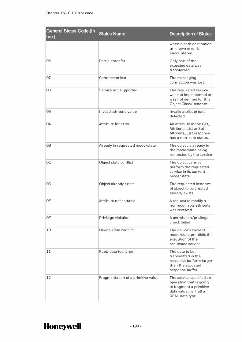
General Status Code (inhex)
Status Name Description of Status
when a path destinationunknown error isencountered.
06 Partial transfer Only part of theexpected data wastransferred.
07 Connection lost The messagingconnection was lost.
08 Service not supported The requested servicewas not implemented orwas not defined for thisObject Class/Instance.
09 Invalid attribute value Invalid attribute datadetected
0A Attribute list error An attribute in the Get_Attribute_List or Set_Attribute_List responsehas a non-zero status.
0B Already in requested mode/state The object is already inthe mode/state beingrequested by the service
0C Object state conflict The object cannotperform the requestedservice in its currentmode/state
0D Object already exists The requested instanceof object to be createdalready exists.
0E Attribute not settable A request to modify anonmodifiable attributewas received.
0F Privilege violation A permission/privilegecheck failed
10 Device state conflict The device’s currentmode/state prohibits theexecution of therequested service.
11 Reply data too large The data to betransmitted in theresponse buffer is largerthan the allocatedresponse buffer
12 Fragmentation of a primitive value The service specified anoperation that is goingto fragment a primitivedata value, i.e. half aREAL data type.
- 198 -
Chapter 15 - CIP Error code

Chapter 15 - CIP Error code
General Status Code (inhex)
Status Name Description of Status
13 Not enough data The service did notsupply enough data toperform the specifiedoperation.
14 Attribute not supported The attribute specified inthe request is notsupported
15 Too much data The service suppliedmore data than wasexpected
16 Object does not exist The object specifieddoes not exist in thedevice.
17 Service fragmentation sequence not inprogress
The fragmentationsequence for thisservice is not currentlyactive for this data.
18 No stored attribute data The attribute data of thisobject was not savedprior to the requestedservice.
19 Store operation failure The attribute data of thisobject was not saveddue to a failure duringthe attempt.
1A Routing failure, request packet toolarge
The service requestpacket was too large fortransmission on anetwork in the path tothe destination. Therouting device wasforced to abort theservice.
1B Routing failure, response packet toolarge
The service responsepacket was too large fortransmission on anetwork in the path fromthe destination. Therouting device wasforced to abort theservice.
1C Missing attribute list entry data The service did notsupply an attribute in alist of attributes that wasneeded by the service toperform the requestedbehavior.
1D Invalid attribute value list The service is returningthe list of attributes
- 199 -

General Status Code (inhex)
Status Name Description of Status
supplied with statusinformation for thoseattributes that wereinvalid.
1E Embedded service error An embedded serviceresulted in an error.
1F Vendor specific error A vendor specific errorhas been encountered.The Additional CodeField of the ErrorResponse defines theparticular errorencountered. Use of thisGeneral Error Codeshould only beperformed when noneof the Error Codespresented in this tableor within an Object Classdefinition accuratelyreflect the error.
20 Invalid parameter A parameter associatedwith the request wasinvalid. This code is usedwhen a parameter doesnot meet therequirements of thisspecification and/or therequirements defined inan Application ObjectSpecification.
21 Write-once value or medium alreadywritten
An attempt was made towrite to a write-oncemedium (e.g. WORMdrive, PROM) that hasalready been written, orto modify a value thatcannot be changed onceestablished.
22 Invalid Reply Received An invalid reply isreceived (e.g. replyservice code does notmatch the requestservice code, or replymessage is shorter thanthe minimum expectedreply size). This statuscode can serve for othercauses of invalid replies.
23 Buffer Overflow The message received islarger than the receivingbuffer can handle. The
- 200 -
Chapter 15 - CIP Error code

Chapter 15 - CIP Error code
General Status Code (inhex)
Status Name Description of Status
entire message wasdiscarded.
24 Message Format Error The format of thereceived message is notsupported by the server.
25 Key Failure in path The Key Segment thatwas included as the firstsegment in the pathdoes not match thedestination module. Theobject specific statusshall indicate which partof the key check failed
26 Path Size Invalid The size of the pathwhich was sent with theService Request is eithernot large enough toallow the Request to berouted to an object ortoo much routing datawas included.
27 Unexpected attribute in list An attempt was made toset an attribute that isnot able to be set at thistime.
28 Invalid Member ID ID The Member IDspecified in the requestdoes not exist in thespecifiedClass/Instance/Attribute
29 Member not settable A request to modify anon-modifiable memberwas received
2A Group 2 only server general failure This error code may onlybe reported byDeviceNet Group 2 Onlyservers with 4K or lesscode space and only inplace of Service notsupported, Attribute notsupported and Attributenot settable.
2B Unknown Modbus Error A CIP to Modbustranslator received anunknown ModbusException Code.
2C Attribute not gettable A request to read a non-readable attribute wasreceived
2D Instance Not Deletable The requested object
- 201 -

General Status Code (inhex)
Status Name Description of Status
instance cannot bedeleted
2E Service Not Supported for SpecifiedPath
The object supports theservice, but not for thedesignated applicationpath (e.g. attribute).NOTE: Not to be used forany set service (useGeneral Status Code0x0E or 0x29 instead)
2F - CF Reserved by CIP forfuture extensions
D0 FF Reserved for Object Class specificerrors
This range of errorcodes is to be used toindicate Object Classspecific errors. Use ofthis range should onlybe performed whennone of the Error Codespresented in this tableaccurately reflect theerror that wasencountered.
15.2 Connection Manager Service Error Codes
The error codes are returned with the response to a Connection Manager Service Request thatresulted in an error. These error codes shall be used to help diagnose the problem with a ServiceRequest. The error code shall be split into an 8 bit general status and one or more 16-bit words ofextended status. Unless specified otherwise, only the first word of extended status shall berequired. Additional words of extended status may be used to specify additional device specificinformation. All devices that originate messages shall be able to handle multiple words of extendedstatus.
The following table provides a summary of the available error codes. Only the type of nodeindicated in the Detected By column shall return the general status/ extended status code. TheDetected By column values are Originator, Router and Target. When detected by Router or Targetdevices these error codes will be contained in the response packet. When detected by Originatorthese error codes can be reported back to the application via an object interface (e.g. ConnectionConfiguration object) or other internal interface.
GeneralStatus
ExtendedStatus
Detected By Explanation and Description
0x00 Service completed successfully
0x01 0x0000through0x00FF
Obsolete.
0x01 0x0100 Router Target CONNECTION IN USE OR
- 202 -
Chapter 15 - CIP Error code

Chapter 15 - CIP Error code
GeneralStatus
ExtendedStatus
Detected By Explanation and Description
DUPLICATE FORWARD OPEN
This extended status code shall bereturned when an originator is tryingto make a connection to a target withwhich the originator may havealready established a connection.
0x01 0x0101through0x0102
Reserved by CIP
0x01 0x0103 Target TRANSPORT CLASS AND TRIGGERCOMBINATION NOT SUPPORTED
A transport class and triggercombination has been specifiedwhich is not supported by the targetapplication.
0x01 0x0104 Reserved by CIP
0x01 0x0105 See CIP SafetySpecification(Volume 5 Chapter3)
0x01
0x01 0x0106 Target OWNERSHIP CONFLICT
The connection cannot beestablished since another connectionhas exclusively allocated some of theresources required for thisconnection. An example of thiswould be that only one exclusiveowner connection can control anoutput point on an I/O Module. If asecond exclusive owner connection(or redundant owner connection) isattempted, this error shall bereturned.
0x01 0x0107 Target TARGET CONNECTION NOT FOUND
This extended status code shall bereturned in response to the Forward_Close request, when the connectionthat is to be closed is not found at thetarget node. Routers shall notgenerate this extended status code. If
- 203 -

GeneralStatus
ExtendedStatus
Detected By Explanation and Description
the specified connection is not foundat the router, the close request shallstill be forwarded using the pathspecified in the Forward_Closerequest.
0x01 0x0108 Router Target INVALID NETWORK CONNECTIONPARAMETER
This extended status code shall bereturned as the result of specifying aconnection type, connection priority,redundant owner or fixed / variablethat is not supported by the device.
NOTE: This extended status code isdeprecated. It is highlyrecommended that 0x011F, 0x0120,0x0121, 0x0122, 0x0123, 0x0124,0x0125 or 0x0132 be used
instead.
0x01 0x0109 Router Target INVALID CONNECTION SIZE
This extended status code is returnedwhen the target or router does notsupport the specified connection size.This could occur at a target becausethe size does not match the requiredsize for a fixed size connection. Itcould occur at a router if therequested size is too large for thespecified network.
An additional status word may followindicating the maximum connectionsize supported by the respondingnode. The additional status word isrequired when issued in response tothe Large_Forward_Open.
NOTE: This extended status code isdeprecated. It is highlyrecommended that 0x0126, 0x0127or 0x0128 be used instead.
0x01 0x010A
through
Reserved by CIP
- 204 -
Chapter 15 - CIP Error code

Chapter 15 - CIP Error code
GeneralStatus
ExtendedStatus
Detected By Explanation and Description
0x010F
0x01 0x0110 Target TARGET FOR CONNECTION NOTCONFIGURED
This extended status code shall bereturned when a connection isrequested to a target application thathas not been configured and theconnection request does not containa data segment for configuration.
Reference section C-1.4.5 – DATASEGMENT
0x01 0x0111 Router Target RPI NOT SUPPORTED.
This extended status code shall bereturned if the device cannot supportthe requested OàT or TàO RPI. Thisextended status code may also beused if the connection time-outmultiplier produces a time-out valuethat is not supported by the device orthe production inhibit time is notvalid.
NOTE: It is highly recommended touse Extended Status 0x0112 whenthe RPI values(s) are not acceptable.
NOTE: Use of this extended statuscode when the connection time-outmultiplier is not supported isdeprecated. It is highlyrecommended that 0x0133 be usedinstead.
NOTE: Use of this extended statuscode when the production inhibittime is not valid is deprecated. It ishighly recommended that 0x011B beused instead.
0x01 0x0112 Router Target RPI VALUE(S) NOT ACCEPTABLE
This error is to be returned when theRPI value(s) in the forward openrequest are outside the range
- 205 -

GeneralStatus
ExtendedStatus
Detected By Explanation and Description
required by the application in thetarget device or the target isproducing at a different interval. Thetarget shall include information withacceptable RPI(s).For this error, theextended status size is 6 16-bit wordsand is formatted as follows:
Data Type Value Explanationof Field
UINT 0x112 Extended statuscode
USINT variable AcceptableOriginator toTarget RPI(see below)type, values:
0 – the RPIspecified inthe forwardopen wasacceptable(the Originatorto Target RPIvalue isignored).1
1. unspecified(used tosuggest analternateRPI, e.g.default)
2. minimumacceptableRPI (usedwhen RPIwas toofast forrange)
3. maximumacceptableRPI (usedwhen RPIwas tooslow forrange)
- 206 -
Chapter 15 - CIP Error code

Chapter 15 - CIP Error code
GeneralStatus
ExtendedStatus
Detected By Explanation and Description
4. requiredRPI tocorrectmismatch(usedwhen dataalreadybeingconsumedat adifferentinterval)
5-255 –reserved
USINT variable AcceptableTarget toOriginator RPI(see below)type, values:
0 – the RPIspecified inthe forwardopen wasacceptable(the Target toOriginator RPIvalue isignored).1
1. unspecified(used tosuggest analternateRPI, e.g.default)
2. minimumacceptableRPI (usedwhen RPIwas toofast forrange)
3. maximumacceptableRPI (usedwhen RPIwas tooslow forrange)
- 207 -

GeneralStatus
ExtendedStatus
Detected By Explanation and Description
4. requiredRPI tocorrectmismatch(usedwhen dataalreadybeingproducedat adifferentinterval,typicallymulticast)
5-255 –reserved
0x01 0x0113 Originator RouterTarget
OUT OF CONNECTIONS
Connection Manager cannot supportany more connections. The maximumnumber of connections supported bythe Connection Manager has alreadybeen created.
0x01 0x0114 Router Target VENDOR ID OR PRODUCT CODEMISMATCH
The Product Code or Vendor IDspecified in the electronic key logicalsegment does not match the ProductCode or Vendor ID of the device. Ifthe compatibility bit is set this errorcode is returned when the requestedVendor ID or Product Code is 0 orthe device cannot emulate thespecified Vendor ID or Product Code.
0x01 0x0115 Router Target DEVICE TYPE MISMATCH
The Device Type specified in theelectronic key logical segment doesnot match the Device Type of thedevice. If the compatibility bit is set
- 208 -
Chapter 15 - CIP Error code

Chapter 15 - CIP Error code
GeneralStatus
ExtendedStatus
Detected By Explanation and Description
this error code is returned when therequested Device Type is 0 or thedevice cannot emulate the specifiedDevice Type.
EXCEPTION: If the compatibility bit isset, Device Type 0 is allowed if therecipient can emulate a device thatreports the deprecated GenericDevice Type Number.
0x01 0x0116 Router Target REVISION MISMATCH
The major and minor revisionspecified in the electronic key logicalsegment does not correspond to avalid revision of the device. If thecompatibility bit is set this error codeis returned when the requested MajorRevision and/or Minor Revision is 0or the device cannot emulate thespecified revision.
0x01 0x0117 Target INVALID PRODUCED ORCONSUMED APPLICATION PATH
The produced or consumedapplication path specified in theconnection path does not correspondto a valid produced or consumedapplication path within the targetapplication. This error could also bereturned if a produced or consumedapplication path was required, butnot provided by a connection request.
NOTE: This extended status code isdeprecated. It is highlyrecommended that 0x012A, 0x012Bor 0x012F be used instead.
- 209 -

GeneralStatus
ExtendedStatus
Detected By Explanation and Description
0x01 0x0118 Target INVALID OR INCONSISTENTCONFIGURATION APPLICATIONPATH
An application path specified for theconfiguration data does notcorrespond to a configurationapplication or is inconsistent with theconsumed or produced applicationpaths. For example the connectionpath specifies float configurationdata while the produced orconsumed paths specify integer data.
NOTE: This extended status code isdeprecated. It is highlyrecommended that 0x0129 or0x012F be used instead.
0x01 0x0119 Target NON-LISTEN ONLY CONNECTIONNOT OPENED
Connection request fails since thereare no non-Listen Only connectionswith the same TàO application pathcurrently open. Refer to Section 3-6for a description of applicationconnection types
The extended status code shall bereturned when an attempt is made toestablish a Listen Only connectiontype to a target, which has no non-Listen Only connections with thesame TàO application path alreadyestablished.
0x01 0x011A Target TARGET OBJECT OUT OFCONNECTIONS
The maximum number of
- 210 -
Chapter 15 - CIP Error code

Chapter 15 - CIP Error code
GeneralStatus
ExtendedStatus
Detected By Explanation and Description
connections supported by thisinstance of the target object has beenexceeded.
For example, the ConnectionManager could support 20connections while the target objectcan only support 10 connections. Onthe 11th Connection Request to thetarget object, this extended statuscode would be used to signify thatthe maximum number ofconnections already exist to thetarget object.
0x01 0x011B Target THE PRODUCTION INHIBIT TIME ISGREATER THAN THE RPI
The Production Inhibit Time isgreater than the Target to OriginatorRPI.
0x01 0x011C Router Target TRANSPORT CLASS NOTSUPPORTED
The transport class requested in theTransport Type/Trigger parameter isnot supported.
0x01 0x011D Router Target TàO PRODUCTION TRIGGER NOTSUPPORTED
The TàO production trigger requestedin the Transport Type/Triggerparameter is not supported.
0x01 0x011E Target DIRECTION NOT SUPPORTED
The direction requested in theTransport Type/Trigger parameter isnot supported.
0x01 0x011F Target INVALID ORIGINATOR TO TARGETNETWORK CONNECTION FIXVAR
This extended status code shall bereturned as the result of specifying an
- 211 -

GeneralStatus
ExtendedStatus
Detected By Explanation and Description
OàT fixed / variable flag that is notsupported.
0x01 0x0120 Target INVALID TARGET TO ORIGINATORNETWORK CONNECTION FIXVAR
This extended status code shall bereturned as the result of specifying aTàO fixed / variable flag that is notsupported.
0x01 0x0121 Target INVALID ORIGINATOR TO TARGETNETWORK CONNECTION PRIORITY
This extended status code shall bereturned as the result of specifying anOàT priority code that is notsupported.
0x01 0x0122 Target INVALID TARGET TO ORIGINATORNETWORK CONNECTION PRIORITY
This extended status code shall bereturned as the result of specifying aTàO priority code that is notsupported.
0x01 0x0123 Target INVALID ORIGINATOR TO TARGETNETWORK CONNECTION TYPE
This extended status code shall bereturned as the result of specifying anOàT connection type that is notsupported.
0x01 0x0124 Router Target INVALID TARGET TO ORIGINATORNETWORK CONNECTION TYPE
This extended status code shall bereturned as the result of specifying aTàO connection type that is notsupported.
0x01 0x0125 Router Target INVALID ORIGINATOR TO TARGETNETWORK CONNECTIONREDUNDANT_OWNER
This extended status code shall bereturned as the result of specifying anOàT Redundant Owner flag that is not
- 212 -
Chapter 15 - CIP Error code

Chapter 15 - CIP Error code
GeneralStatus
ExtendedStatus
Detected By Explanation and Description
supported.
0x01 0x0126 Target INVALID CONFIGURATION SIZE
This extended status code is returnedwhen the target device determinesthat the data segment provided in theConnection_Path parameter did notcontain an acceptable number of 16-bit words for the configurationapplication path requested.
An additional status word shall followindicating the maximumconfiguration size supported.
Data Type Value Explanationof Field
UINT 0x0126 ExtendedStatus Code
UINT Size Max Size inWords
0x01 0x0127 Router Target INVALID ORIGINATOR TO TARGETNETWORK CONNECTION SIZE
This extended status code is returnedby the target when the size of theconsuming object declared in theForward_Open request and availableon the target does not match the sizedeclared in the OàT NetworkConnection Parameter.
This extended status code is returnedby a router when it cannot supportthe size requested in the OàT NetworkConnection Parameter.
An additional status word shall followindicating the maximum originator totarget size supported.
Data Type Value Explanationof Field
UINT 0x0127 ExtendedStatus Code
- 213 -

GeneralStatus
ExtendedStatus
Detected By Explanation and Description
UINT Size Max Size inbytes
0x01 0x0128 Router Target INVALID TARGET TO ORIGINATORNETWORK CONNECTION SIZE
This extended status code is returnedby the target when the size of theproducing object declared in theForward Open request and availableon the target does not match the sizedeclared in the TàO NetworkConnection Parameter.
This extended status code is returnedby a router when it cannot supportthe size requested in the TàO NetworkConnection Parameter.
An additional status word shall followindicating the maximum target tooriginator size supported.
Data Type Value Explanationof Field
UINT 0x0128 ExtendedStatus Code
UINT Size Max Size inbytes
0x01 0x0129 Target INVALID CONFIGURATIONAPPLICATION PATH
The configuration application pathspecified in the connection path doesnot correspond to a validconfiguration application path withinthe target application. This errorcould also be returned if aconfiguration application path wasrequired, but not provided by aconnection request.
0x01 0x012A Target INVALID CONSUMING APPLICATIONPATH
The consumed application pathspecified in the connection path does
- 214 -
Chapter 15 - CIP Error code

Chapter 15 - CIP Error code
GeneralStatus
ExtendedStatus
Detected By Explanation and Description
not correspond to a valid consumedapplication path within the targetapplication. This error could also bereturned if a consumed applicationpath was required, but not providedby a connection request.
0x01 0x012B Target INVALID PRODUCING APPLICATIONPATH
The produced application pathspecified in the connection path doesnot correspond to a valid producedapplication path within the targetapplication. This error could also bereturned if a produced applicationpath was required, but not providedby a connection request.
0x01 0x012C Target CONFIGURATION SYMBOL DOESNOT EXIST
Configuration Symbol does not exist.The originator attempts to connect toa configuration tag name, but thename is not on the list of tags definedon the target.
0x01 0x012D Target CONSUMING SYMBOL DOES NOTEXIST
Consuming Symbol does not exist.The originator attempts to connect toa consuming tag name, but the nameis not on the list of tags defined onthe target.
0x01 0x012E Target PRODUCING SYMBOL DOES NOTEXIST
Producing Symbol does not exist. Theoriginator attempts to connect to aproducing tag name, but the name isnot on the list of tags defined on thetarget.
0x01 0x012F Target INCONSISTENT APPLICATION PATHCOMBINATION
- 215 -

GeneralStatus
ExtendedStatus
Detected By Explanation and Description
The combination of configurationand/or consume and/or produceapplication paths specified in theconnection path are inconsistent witheach other.
0x01 0x0130 Target INCONSISTENT CONSUME DATAFORMAT
Information in the data segment isnot consistent with the format of theconsumed data. For example theconfiguration data specifies floatconfiguration data while theconsumed path specifies integerdata.
0x01 0x0131 Target INCONSISTENT PRODUCE DATAFORMAT
Information in the data segment isnot consistent with the format of theproduced data. For example theconfiguration data specifies floatconfiguration data while theproduced path specifies integer data.
0x01 0x0132 Target NULL FORWARD OPEN FUNCTIONNOT SUPPORTED
The target does not support thefunction requested by the NullForward Open. The requestedfunction may be “ping a device”,“configure a device’s application”, or“reconfigure a target device’sapplication”.
0x01 0x0133 Target Router CONNECTION TIMEOUTMULTIPLIER NOT ACCEPTABLE
This extended status code shall bereturned as the result of specifying aconnection timeout multiplier valuethat is reserved or that produces atimeout value that is too large tosupport in the device.
0x01 0x0134 Target MISMATCHED TàO NETWORK
- 216 -
Chapter 15 - CIP Error code

Chapter 15 - CIP Error code
GeneralStatus
ExtendedStatus
Detected By Explanation and Description
CONNECTION SIZE
This extended status code shall bereturned when an originator requeststo open a Multicast connection to aTàO application path that is alreadybeing produced for anotherconnection and the Size field in theTàO Network Connection Parametersin this request is valid but doesn’tmatch the existing connection’s Sizefield.
0x01 0x0135 Target MISMATCHED TàO NETWORKCONNECTION FIXVAR
This extended status code shall bereturned when an originator requeststo open a Multicast connection to aTàO application path that is alreadybeing produced for anotherconnection and the Fixed/Variable bitin the TàO Network ConnectionParameters in this request is valid butdoesn’t match the existingconnection’s Fixed/Variable bit.
0x01 0x0136 Target MISMATCHED TàO NETWORKCONNECTION PRIORITY
This extended status code shall bereturned when an originator requeststo open a Multicast connection to aTàO application path that is alreadybeing produced for anotherconnection and the Priority field inthe TàO Network ConnectionParameters in this request is valid butdoesn’t match the existingconnection’s Priority field.
0x01 0x0137 Target MISMATCHED TRANSPORT CLASS
This extended status code shall bereturned when an originator requeststo open a Multicast connection to aTàO application path that is alreadybeing produced for another
- 217 -

GeneralStatus
ExtendedStatus
Detected By Explanation and Description
connection and the Transport Classin this request is valid but doesn’tmatch the existing connection’sTransport Class.
0x01 0x0138 Target MISMATCHED TàO PRODUCTIONTRIGGER
This extended status code shall bereturned when an originator requeststo open a Multicast connection to aTàO application path that is alreadybeing produced for anotherconnection and the TàO ProductionTrigger in this request is valid butdoesn’t match the existingconnection’s TàO Production Trigger.
0x01 0x0139 Target MISMATCHED TàO PRODUCTIONINHIBIT TIME SEGMENT
This extended status code shall bereturned when an originator requeststo open a Multicast connection to anapplication path that is already beingproduced for another connection andthe PIT in this request is valid butdoesn’t match the existingconnection’s PIT.
0x01 0x013A
through0x0202
Reserved by CIP
0x01 0x0203 Originator CONNECTION TIMED OUT
This extended status code shall occurwhen a connection has timed-out.
0x01 0x0204 Originator RouterTarget
UNCONNECTED REQUEST TIMEDOUT
An originator or router processing anUnconnected_Send, Forward_Open,Large_Forward_Open, or Forward_Close service shall return anUnconnected Request Timed Outerror when the request cannot be
- 218 -
Chapter 15 - CIP Error code

Chapter 15 - CIP Error code
GeneralStatus
ExtendedStatus
Detected By Explanation and Description
delivered to the next device in thepath (e.g the link specific retries fail),the allotted time is not sufficient toprocess the request, or no reply isreceived within the time specified bythe Time_tick/Time-out_ticksparameters.
A target processing a Forward_Open,Large_Forward_Open, or Forward_Close service may return anUnconnected Request Timed Outerror when the allotted time is notsufficient to process the request.
See section 3-5.4.1.3 UnconnectedRequest Timing for moreinformation.
0x01 0x0205 Router PARAMETER ERROR INUNCONNECTED REQUEST SERVICE
For example, this shall be caused by aConnection Tick Time (see section 3-5.4.1.3) and Connection time-outcombination in an Unconnected_Send, Forward_Open, or Forward_Close service that is not supported bya router.
0x01 0x0206 Originator Router MESSAGE TOO LARGE FORUNCONNECTED_SEND SERVICE
This shall be caused when theUnconnected_Send is too large to besent out on a network.
0x01 0x0207 Originator Router UNCONNECTED ACKNOWLEDGEWITHOUT REPLY
The message was sent via theunconnected message service and anacknowledge was received but a dataresponse message was not received.
0x01 0x0208
through0x0300
Reserved by CIP
- 219 -

GeneralStatus
ExtendedStatus
Detected By Explanation and Description
0x01 0x0301 Originator RouterTarget
NO BUFFER MEMORY AVAILABLE
The extended status code shall occurwhen insufficient connection buffermemory is available in the device.
0x01 0x0302 Originator RouterTarget
NETWORK BANDWIDTH NOTAVAILABLE FOR DATA
This extended status code shall bereturned by any device in the paththat is a producer and cannotallocate sufficient bandwidth for theconnection on its link. This can onlyoccur for connections that arespecified as scheduled priority.
0x01 0x0303 Originator RouterTarget
NO CONSUMED CONNECTION IDFILTER AVAILABLE
Any device in the path that contains alink consumer for the connection anddoes not have an availableconsumed_connection_id filteravailable shall return this extendedstatus code.
0x01 0x0304 Originator RouterTarget
NOT CONFIGURED TO SENDSCHEDULED PRIORITY DATA
If requested to make a connectionthat specifies scheduled priority, anydevice that is unable to send packetsduring the scheduled portion of thenetwork update time interval shallreturn this extended status code. Forexample, on ControlNet this codeshall be returned by a node whoseMAC ID is greater than maximumscheduled node (SMAX).
0x01 0x0305 Router SCHEDULE SIGNATURE MISMATCH
This extended status code shall bereturned when the connectionscheduling information in theoriginator device is not consistentwith the connection schedulinginformation on the target network.
- 220 -
Chapter 15 - CIP Error code

Chapter 15 - CIP Error code
GeneralStatus
ExtendedStatus
Detected By Explanation and Description
0x01 0x0306 Router SCHEDULE SIGNATURE VALIDATIONNOT POSSIBLE
This extended status code shall bereturned when the connectionscheduling information in theoriginator device cannot be validatedon the target network. For example,on ControlNet this code shall bereturned when there is no keeper inthe master state.
0x01 0x0307
through0x0310
Reserved by CIP
0x01 0x0311 Originator Router PORT NOT AVAILABLE
A Port specified in a Port Segment isNot Available or does not exist.
0x01 0x0312 Originator Router LINK ADDRESS NOT VALID
Link Address specified in PortSegment Not Valid
This extended status code is theresult of a port segment that specifiesa link address that is not valid for thetarget network type. This extendedstatus code shall not be used for linkaddresses that are valid for the targetnetwork type but do not respond.
0x01 0x0313
through0x0314
Reserved by CIP
0x01 0x0315 Originator RouterTarget
INVALID SEGMENT IN CONNECTIONPATH
Invalid Segment Type or SegmentValue in Connection Path
This extended status code is theresult of a device being unable todecode the connection path. Forexample, this could be caused by anunrecognized path type or a
- 221 -

GeneralStatus
ExtendedStatus
Detected By Explanation and Description
segment type occurringunexpectedly. This extended statuscode shall only be used when noother more specific extended statuscode provided in this table applies.
0x01 0x0316 Router Target FORWARD CLOSE SERVICECONNECTION PATH MISMATCH
The connection path in the Forward_Close service does not match theconnection path in the connectionbeing closed. This extended statuserror code has been deprecatedbecause the Forward_Close serviceuses the connection triad formatching and doesn’t use theconnection path.
0x01 0x0317 Originator RouterTarget
SCHEDULING NOT SPECIFIED
Either the Schedule NetworkSegment was not present or theEncoded Value in the ScheduleNetwork Segment is invalid (i.e. 0).
0x01 0x0318 Originator Router LINK ADDRESS TO SELF INVALID
Under some conditions (depends onthe device), a link address in the PortSegment which points to the samedevice (loopback to yourself) isinvalid.
0x01 0x0319 Router Target SECONDARY RESOURCESUNAVAILABLE
In a dual chassis redundant system, aconnection request that is made tothe primary system shall beduplicated on the secondary system.If the secondary system is unable toduplicate the connection request,then this extended status code shallbe returned.
0x01 0x031A Target RACK CONNECTION ALREADYESTABLISHED
- 222 -
Chapter 15 - CIP Error code

Chapter 15 - CIP Error code
GeneralStatus
ExtendedStatus
Detected By Explanation and Description
A request for a module connectionhas been refused because part of thecorresponding data is alreadyincluded in a rack connection.
0x01 0x031B Target MODULE CONNECTION ALREADYESTABLISHED
A request for a rack connection hasbeen refused because part of thecorresponding data is alreadyincluded in a module connection.
0x01 0x031C Originator RouterTarget
MISCELLANEOUS
This extended status is returned whenno other extended status codeapplies for a connection related error.
0x01 0x031D Target REDUNDANT CONNECTIONMISMATCH
This extended status code shall bereturned when the following fields donot match when attempting toestablish a redundant ownerconnection to the same target path:
l OàT_RPI;
l OàT_connection_parameters;
l TàO_RPI;
l TàO_connection_parameters;
l xport_type_and_trigger.
0x01 0x031E Target NO MORE USER CONFIGURABLELINK CONSUMER RESOURCESAVAILABLE IN THE PRODUCINGMODULE
A target shall return this extendedstatus when the configured numberof consumers for a producingapplication are already in use.
0x01 0x031F Target NO USER CONFIGURABLE LINKCONSUMER RESOURCESCONFIGURED IN THE PRODUCINGMODULE
- 223 -

GeneralStatus
ExtendedStatus
Detected By Explanation and Description
A target shall return this extendedstatus when there are no consumersconfigured for a producingapplication to use.
0x01 0x0320 –
0x07FF
Vendor specific
0x01 0x0800 Originator Router NETWORK LINK OFFLINE
Network link in path to module isoffline
0x01 0x0801 –
0x080F
See CIP Safety Specification (Volume 5, Chapter 3)
0x01 0x0810 Target NO TARGET APPLICATION DATAAVAILABLE
This extended status code is returnedwhen the target application does nothave valid data to produce for therequested connection.
0x01 0x0811 Originator NO ORIGINATOR APPLICATION DATAAVAILABLE
This extended status code is returnedwhen the originator application doesnot have valid data to produce for therequested connection.
0x01 0x0812 Originator Router NODE ADDRESS HAS CHANGEDSINCE THE NETWORK WASSCHEDULED
A router on a scheduled network (e.g.:ControlNet) has a different nodeaddress than the value configured inthe connection originator.
0x01 0x0813 Router Target NOT CONFIGURED FOR OFF-SUBNET MULTICAST
A multicast connection has beenrequested between a producer and aconsumer that are on differentsubnets, and the producer is notconfigured for off-subnet multicast.
- 224 -
Chapter 15 - CIP Error code

Chapter 15 - CIP Error code
GeneralStatus
ExtendedStatus
Detected By Explanation and Description
0x01 0x0814 Target INVALID PRODUCE/CONSUME DATAFORMAT
Information in the data segmentindicates that the format of theproduced and/or consumed data isnot valid.
NOTE: This extended status code isdeprecated. It is highlyrecommended that 0x0130 or0x0131 be used instead.
0x01 0x0815
through0x08FF
Reserved by CIP
0x01 0x0900 Originator Router (D)TLS Fatal Alert 0: Close Notify1
This error code denotes that one sideof the (D)TLS connection hasrequested that the connection beclosed.
0x01 0x0901 Originator Router (D)TLS Fatal Alert 10: UnexpectedMessage1
An inappropriate message wasreceived on the (D)TLS handshake.
0x01 0x0902 Originator Router (D)TLS Fatal Alert 20: Bad RecordMAC1
This alert is returned if a (D)TLSrecord is received with an incorrectMAC. This alert is also returned if aTLSCiphertext decrypted in an invalidway.
0x01 0x0903 Originator Router (D)TLS Fatal Alert 22: RecordOverflow1
This indicates that a TLSCiphertextrecord was received that had a lengthof more than 2^14 + 2048 bytes, or arecord decrypted to aTLSCompressed record with morethan 2^14 + 2048 bytes.
0x01 0x0904 Originator Router (D)TLS Fatal Alert30: Decompression
- 225 -

GeneralStatus
ExtendedStatus
Detected By Explanation and Description
Failure1
The (D)TLS decompression functionreceived improper input (e.g., datathat would expand to excessivelength).
0x01 0x0905 Originator Router (D)TLS Fatal Alert40: HandshakeFailure1
Reception of a handshake_failurealert message indicates that thesender was unable to negotiate anacceptable set of security parametersgiven the options available.
0x01 0x0906 Originator Router (D)TLSFatal Alert 42: Bad Certificate1
A certificate was corrupt, containedsignatures that did not verifycorrectly, etc…
0x01 0x0907 Originator Router (D)TLSFatal Alert 43: UnsupportedCertificate1A certificate was of anunsupported type
0x01 0x0908 Originator Router (D)TLS Fatal Alert 44: CertificateRevoked1A certificate was revoked byits signer
0x01 0x0909 Originator Router (D)TLSFatal Alert 45: CertificateExpired1
A certificate has expired or is notcurrently valid
0x01 0x090A Originator Router (D)TLSFatal Alert 46: CertificateUnknown1
Some other (unspecified) issue arosein processing the certificate,rendering it unacceptable.
0x01 0x090B Originator Router (D)TLSFatal Alert 47: IllegalParameter1
A field in the handshake was out ofrange or inconsistent with otherfields.
0x01 0x090C Originator Router (D)TLS Fatal Alert 48: Unknown CA1
- 226 -
Chapter 15 - CIP Error code

Chapter 15 - CIP Error code
GeneralStatus
ExtendedStatus
Detected By Explanation and Description
A valid certificate chain or partialchain was received, but the certificatewas not accepted because the CAcertificate could not be located orcouldn’t be matched with a known,trusted CA.
0x01 0x090D Originator Router (D)TLSFatal Alert 49: Access Denied1
A valid certificate was received, butwhen access control was applied, thesender decided not to proceed withnegotiation.
0x01 0x090E Originator Router (D)TLSFatal Alert 50: Decode Error1
A message could not be decodedbecause some field was out of thespecified range or the length of themessage was incorrect.
0x01 0x090F Originator Router (D)TLSFatal Alert 51: Decrypt Error1
A handshake cryptographic operationfailed, including being unable tocorrectly verify a signature or validatea Finished message.
0x01 0x0910 Originator Router (D)TLSFatal Alert 70: ProtocolVersion1
The protocol version the client hasattempted to negotiate is recognizedbut not supported (For example, oldprotocol version might be avoided forsecurity reasons).
0x01 0x0911 Originator Router (D)TLSFatal Alert 71: InsufficientSecurity1
Returned instead of handshake_failure when a negotiation has failedspecifically because the serverrequires ciphers more secure thanthose supported by the client.
0x01 0x0912 Originator Router (D)TLSFatal Alert 80: Internal Error1
An internal error unrelated to thepeer or the correctness of the
- 227 -

GeneralStatus
ExtendedStatus
Detected By Explanation and Description
protocol (such as a memoryallocation failure) makes itimpossible to continue.
0x01 0x0913 Originator Router (D)TLSFatal Alert 86: InappropriateFallback1
The (D)TLS server detected aninappropriate protocol downgrade.
0x01 0x0914 Originator Router (D)TLSFatal Alert 110: UnsupportedExtension1
Sent by clients that receive anextended server hello containing anextension that they did not put in thecorresponding client hello.
0x01 0x0915 Originator Router (D)TLSFatal Alert: Unknown PSKIdentity1
The PSK identity sent within thehandshake is not recognized.
0x01 0x0916
through0x09FF
Reserved for security related status.
0x01 0x0A00
through0xFCFF
Reserved by CIP
0x01 0xFD00
through0xFFFF
Do not use
0x02 Empty Originator Router RESOURCE UNAVAILABLE FORUNCONNECTED_SEND
The device lacks the resources to fullyprocess the Unconnected SendRequest.
0x04 Empty Router PATH SEGMENT ERROR INUNCONNECTED SEND
Indicates the Router experienced aparsing error when extracting theExplicit Messaging Request from the
- 228 -
Chapter 15 - CIP Error code

Chapter 15 - CIP Error code
GeneralStatus
ExtendedStatus
Detected By Explanation and Description
Unconnected Send Request ServiceData.
0x09 Index toElement
Target ERROR IN DATA SEGMENT.
This general status code shall bereturned when there is an error in thedata segment of a forward open.
The Extended Status shall be theindex to where the error wasencountered in the Data Segment(Reference section C-1.4.5 – DATASEGMENT).
0x0C Optional Target OBJECT STATE ERROR
This general status code shall bereturned when the state of the targetobject of the connection prevents theservice request from being handled.The Extended Status reports theobject's present state. The extendedstatus is optional.
For example, a target (application)object of the connection may need tobe in an edit mode before attributescan be set. This is different from aservice being rejected due to thestate of the device.
0x10 Optional Router Target DEVICE STATE ERROR
This general status code shall bereturned when the state of the deviceprevents the service request frombeing handled. The Extended Statusreports the device's present state. The extended status is optional.
For example, a controller may have akey switch which when set to the"hard run" state causes ServiceRequests to several different objectsto fail (i.e. program edits). Thisgeneral status code would then bereturned.
0x13 None Router Target NOT ENOUGH DATA
- 229 -

GeneralStatus
ExtendedStatus
Detected By Explanation and Description
The service did not supply enoughdata to perform the specifiedoperation.
0x15 None Router Target TOO MUCH DATA
The service supplied more data thanwas expected.
Table Footnotes:
1. Errors dealing with a (D)TLS connection come from a layer below EtherNet/ IP, and assuch would not actually be sent “in response” to the CIP messages. However, these errorvalues need to be exposed for proper debugging and troubleshooting of CIP Security. Assuch, it is expected that the (D)TLS errors marked by this footnote would come from the(D)TLS layer, yet be exposed by the client as an error on the relevant CIP message.
2. 0x00 – No Error
3. 0xFF – Honeywell specific General Error
4. 0x01 – 0xEF - General CIP Error Code returned by the IO Modules
15.3 Honeywell specific Extended error code
GeneralStatus
Explanation and Description
0 x 01 Internal error code for Connection failure
0 x 02 TCP Connection Failure or Reg Session Failure
0 x 03 Mismatch of either Connection Serial Number, Vendor ID orOriginator Serial Number in the Fwd Open response
0 x 04 CPF Item Count invalid in the Fwd Open response
0 x 05 Multi cast address invalid in the Fwd Open response
0 x 06 The sin_family values is not 2 - in the Fwd Open response
0 x 07 Socket ID Invalid in the Fwd Open response
0 x 08 T2O Timeout – no T2O data for the timeout period
0 x 09 IO Stale data – internal error code set on not receiving any IO datafor 20 seconds
0 x FF Miscellaneous internal status error code
- 230 -
Chapter 15 - CIP Error code

APPENDIX - A
16.1 Third Party EIP Network Component Details
l Configuring a Stratix switch for Ethernet/IP™ integration
l Tofino firewall configuration
16.2 Configuring a Stratix switch for Ethernet/IP™integration
Stratix switch 8000 with IOS firmware revision 15.0 is used for connecting the Ethernet/IP™-compatible I/O devices and the ControlLogix PLC to the C300 controllers. For more informationabout Stratix 8000 and Stratix 5700 switches, see Rockwell Literature Library.
Stratix 5700 and Stratix 8000 switches have been qualified with IOS (as detailed in the sectionNetwork requirements) in R501 for connecting Ethernet/IP devices and controlLogix PLC in“Through EIM” topology.
Perform the following tasks to install the switch configuration files to the node, and configure theStratix switches for Ethernet/IP™ integration. Use the command line interface of the switch andthe correct switch startup configuration file to perform the following tasks.
16.2.1 Prerequisites
Before beginning the procedures in this section, ensure that you verify the following:
l You have an RS-232 cable configured, as required by the switch vendor, to connect thecomputer’s serial port to the communication port of the switch.
l You have downloaded HyperTerminal and Telnet is enabled on the operating system used asthe interface to the switch.
l You have reviewed the Stratix switch documentation at Rockwell Literature library.
16.2.2 To configure the Stratix switch for Ethernet/IP™ integration
1. Connect to the switch. See Connecting locally to the switch.
2. Verify the Stratix switches have the IOS version qualified by Honeywell as listed in the SCN foryour release. See Checking the version of the switch IOS.
3. Configure the switch. See Configuring switch interface options
4. Load the switch configuration file. See Loading the switch configuration file
- 231 -
CHAPTER
16

l Connecting locally to the switch
l Checking the version of the switch IOS
l Accessing switch configuration files
l Configuring switch interface options
l Loading the switch configuration file
l Switch Maintenance
16.2.3 Connecting locally to the switch
Perform the following procedure to connect to the switch and start HyperTerminal.
ATTENTION
Do not turn on the switch until instructed to do so.
To connect locally to the switch
1. Connect the RS-232 cable to the communication port of the switch and the computer’s serialport.
2. Click Start > All Programs > Accessories > Communications > HyperTerminal.
3. On the Connection Description dialog box, specify a name that describes the connection andclick OK.
4. In the Icon box, click the appropriate icon, and click OK.
5. On the Connect To dialog box, select the serial port used by the computer from the ConnectUsing box and click OK.
6. From the Connect To dialog box, select the serial port being used by the computer and clickOK.
7. From the Properties page, configure the following port settings:
l Bits per second: 9600
l Data bits: 8
l Parity: NONE
l Stop bits: 1
l Flow control: NONE
8. Click OK.
Results
The switch is connected.
16.2.4 Checking the version of the switch IOS
Switches with unqualified IOS have unpredictable performance. Therefore, perform the followingprocedure to check the IOS version.
- 232 -
Chapter 16 - Appendix - A

Chapter 16 - Appendix - A
l The switch configuration file is qualified with Stratix 8000 for Ethernet/IP™ with IOS firmwarerevision 15.0. The switch configuration file location for the Stratix 8000 is as follows C:\ProgramFiles (x86)\Honeywell\FTEDriver\SwitchConfigurationFiles\stratix 8000
l The switch configuration file is qualified with Stratix 5700 for Ethernet/IP™ with IOS firmwarerevision 15.2(5). The switch configuration file location for the Stratix 5700 is as followsC:\Program Files (x86)\Honeywell\FTEDriver\SwitchConfigurationFiles\stratix 5700
Prerequisites
Ensure that you have downloaded and installed the HyperTerminal application.
To check the version of the Stratix switch IOS
1. Open Hyper Terminal and log in to the switch.
2. Run the following command to check the IOS version:
show boot
If the IOS version is not qualified by Honeywell as listed in the SCN, contact HoneywellNetwork Services for the procedure to upgrade the IOS.
Results
The version of the IOS is displayed.
16.2.5 Accessing switch configuration files
Switch configuration files are packaged with the FTE driver and are copied to the following locationwhen you run the FTE driver installation package.
\Honeywell\FTEDriver\SwitchConfigurationFiles\stratix 8000
\Honeywell\FTEDriver\SwitchConfigurationFiles\stratix 5700
If you have not installed FTE, access the switch configuration files from the Experion PKSInstallation media at the Media Drive:\FTEDriver\SwitchConfiguration location. Afterconnecting to the switch, use the command line interface (CLI) of the switch to configure theswitch options. If the switch does not respond, press ENTER and wait for the prompt (>) to appear.The following table lists the conventions used in the switch configuration procedures andexamples.
- 233 -

Convention (Example) Description
Enter host name [Switch] :Stratix_EIP Text in the terminal displayappears in the followingfont:
commands
Stratix_EIP#config t Values that are entered bythe user are in bold.
Stratix_EIP(config)#int vlan1 Arguments for which theuser provides the requiredinputs are bold anditalicized.
Press RETURN to get started! <ENTER> Non-printing characters,such as passwords or Enterkey are in angle brackets(<>).
Switch configuration files for the Stratix 8000 switch
The following are the Stratix switch configuration files, which are locatedat:\Honeywell\FTEDriver\SwitchConfigurationFiles\stratix 8000\
- 234 -
Chapter 16 - Appendix - A

Chapter 16 - Appendix - A
Stratix switchconfiguration file
Port information
eip_stratix8000_1u_8.txt
This file is for the Stratix 8000 switch in DIRECT Topology,which contains 8 ports.
l 1 uplink port configuration
l 2 ETAP port configurations
l 5 ports are configured for connecting EIP IO Devices
eip_stratix8000_1u_16.txt
This file is for the Stratix 8000 switch in DIRECT Topology,which contains 16 ports.
l 1 uplink port configuration
l 2 ETAP port configurations
l 13 ports are configured for connecting EIP IO Devices
eip_stratix8000_1u_24.txt
This file is for the Stratix 8000 switch in DIRECT Topology,which contains 24 ports.
l 1 uplink port configuration
l 2 ETAP port configurations
l 21 ports are configured for connecting EIP IO Devices
eim_eip_stratix8000_1u_8.txt
This file is for the Stratix 8000 switch in THROUGH EIMTopology, which contains 8 ports.
l 1 uplink port configuration
l 2 EIM port configurations
l 2 ETAP Port
l 3 IO/Device/CLX port
eim_eip_stratix8000_1u_16.txt
This file is for the QRS port Stratix 8000 switch when usedin UOC topologies.
l 1 uplink port configuration
l 2 EIM port configurations
l 2 ETAP Port
l 11 IO/Device/CLX port
uoc_eip_stratix8000_1u_8
This file is for the Stratix 8000 switch in THROUGH UOCTopology, which contains 8 ports.
l 1 uplink port configuration
l 2 UOC port configurations
l 2 ETAP Port
- 235 -

Stratix switchconfiguration file
Port information
l 3 IO/Device/CLX port
uoc_eip_stratix8000_1u_16
This file is for the Stratix 8000 switch in THROUGH UOCTopology, which contains 16 ports (8 + 8).
l 1 uplink port configuration
l 2 UOC port configurations
l 2 ETAP Port
l 11 IO/Device/CLX port
uoc_eip_stratix8000_1u_24
This file is for the Stratix 8000 switch in THROUGH UOCTopology, which contains 24 ports (8 + 8 + 8).
l 1 uplink port configuration
l 2 UOC port configurations
l 2 ETAP Port
l 19 IO/Device/CLX port
eim_eip_stratix8000_1u_24.txt
This file is for the Stratix 8000 switch in THROUGH EIMTopology, which contains 24 ports (8 + 8 + 8).
l 1 uplink port configuration
l 2 EIM port configurations
l 2 ETAP Port
l 19 IO/Device/CLX port
eim_eip_stratix5700_1u_8.txt
This file is for the Stratix 5700 switch in THROUGH EIMTopology, which contains 8 ports.
l 2 EIM port configurations
l 2 ETAP Port
l 2 IO/Device/CLX port
l 2 DLR ports
uoc_eip_stratix5700_1u_8
This file is for the Stratix 5700 switch in THROUGH UOCTopology, which contains 8 ports.
l 2 UOC port configurations
l 2 ETAP Port
l 2 IO/Device/CLX port
l 2 DLR ports
- 236 -
Chapter 16 - Appendix - A

Chapter 16 - Appendix - A
NOTE
l Stratix 5700 model number qualified with EIM-EIP: 1783-BMS10CGN
l Stratix 5700 must be upgraded with s5700-universal-tar.152-3.EA1.fc2.tar to getDLR configuration option
l 1783-BMS10CGN: This model supports DLR on two ports only (Port 7 and Port 8)
l Stratix switch 8000 and 5700 configuration files present inside\Honeywell\FTEDriver\SwitchConfigurationFiles folder are typical exampleconfigurations. Users are free to modify the port usage/assignments based on theirneeds. But it is strictly recommended to follow port settings as recommended inthese example files for individual port types. It is also recommended to never modifythe example files present in this location. Please copy the files in some other locationbefore editing those to modify port assignments.
16.2.6 Configuring switch interface options
The procedures in this section describe how to enable the configuration dialog and set the basicmanagement setup in the switch. Additionally, it also describes how to set up the switch IP address.Establishing an IP address allows you to use Telnet and FTP sessions to save and restoreconfiguration options.
ATTENTION
The procedures in this section contain multiple instances of switch display for reference.The text in the switch display instances are formatted as follows:
l The commands and some of the options in the switch display instances areformatted bold. Therefore, the text in bold should be typed as it appears.
l Sample inputs that must be provided by the user are formatted bold and italicized(For example: Stratix_EIP). Ensure that you specify an appropriate value thatmatches your requirement.
l Press the Enter key after you type the required command or option.
- 237 -

To configure the switch interface options
1. When the following display appears, specify the required values.
The host name is unique for each switch. The following values are used asexamples in this procedure:
Option Example
host name Stratix_EIP
enable secret Stratix_EIP1
virtual terminal password EIP1
enable password Stratix_EIP1
2. When the following display appears, specify the required details.
The following is an example for your reference. Press the Space bar to advance thedisplay when it pauses.
Enter host name [Switch] :Stratix_EIP
The enable secret is a password used to protect access toprivileged EXEC and configuration modes. This password, afterentered, becomes encrypted in the configuration.Enter enable secret: Stratix_EIP1
The enable password is used when you do not specify an enablesecret password, with some older software versions, and someboot images.Enter enable password:EIP1
The virtual terminal password is used to protect access to therouter over a network interface.Enter virtual terminal password: Stratix_EIP1
Configure SNMP Network Management? [no]: N
3. After the configuration display is complete, the switch dialog appears. Specify therequired values.
Enter interface name used to connect to the management networkfrom the above interface summary :vlan1
Configuring interface Vlan1:
Configure IP on this interface ? [yes/no]: N
Would you like to enable as a cluster command switch?[yes/no]: N
- 238 -
Chapter 16 - Appendix - A

Chapter 16 - Appendix - A
The following is an abridged example of what displays after the VLAN1configuration. Press the SPACE BAR to advance the display when it pauses.
4. After the configuration display is complete, the following switch dialog appears. Type2 and press ENTER to save the switch configuration.
- 239 -

Setting up the IP address for the switch
1. Use the enable command and the enable secret string that was established earlier, in the Toconfigure the switch interface options procedure. Stratix_EIP1 is used in the followingexample. Specify the required values.
Press RETURN to get started! <ENTER>
Stratix_EIP>enablePassword: Stratix_EIP1
Stratix_EIP#config t
enter configuration commands, one per line. End with CNTL/Z
2. If you have to use VLAN 101, initialize VLAN 101 by performing the following additional steps:
a. Type the following:
vlan 101
b. Type the following:
exit
Otherwise, go to the next step.
3. To enable Telnet and FTP, run one of the following commands:
l To configure VLAN1, type:
int vlan1
l To configure VLAN101, type:
int vlan101
Stratix_EIP(config)#int vlan1
4. The following is used for the IP address and subnet mask in the following switch display.
10.1.4.253 255.255.255.0
Stratix_EIP(config-if)#ip address10.1.4.253255.255.255.0Stratix_EIP(config-if)#no shutdownStratix_EIP(config-if)#exit
5. Type exit and type write.
The switch option configuration is complete. You can now download the appropriate switchconfiguration file.
16.2.7 Loading the switch configuration file
The following procedure uses the Xmodem file transfer utility of Hyperterminal to transfer thecorrect switch configuration file to the switch. After downloading the switch configuration file, writethe configuration back to the switch memory.
- 240 -
Chapter 16 - Appendix - A
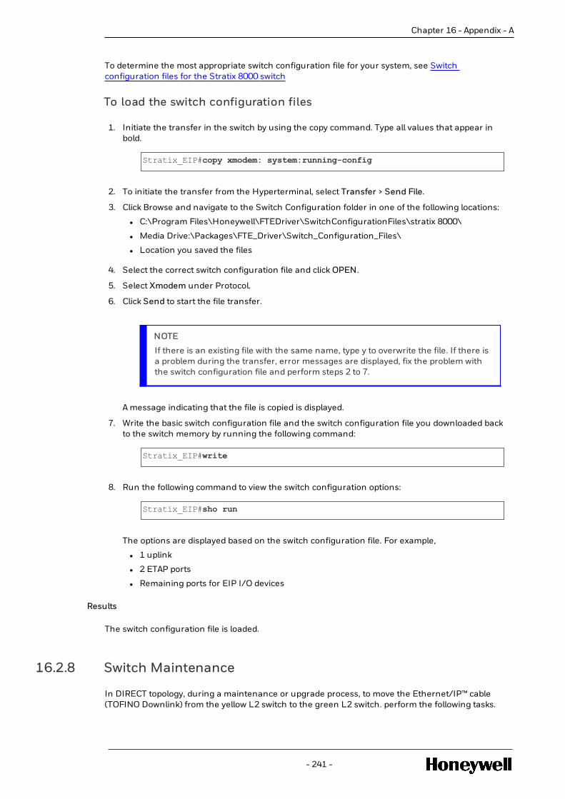
Chapter 16 - Appendix - A
To determine the most appropriate switch configuration file for your system, see Switchconfiguration files for the Stratix 8000 switch
To load the switch configuration files
1. Initiate the transfer in the switch by using the copy command. Type all values that appear inbold.
Stratix_EIP#copy xmodem: system:running-config
2. To initiate the transfer from the Hyperterminal, select Transfer > Send File.
3. Click Browse and navigate to the Switch Configuration folder in one of the following locations:
l C:\Program Files\Honeywell\FTEDriver\SwitchConfigurationFiles\stratix 8000\
l Media Drive:\Packages\FTE_Driver\Switch_Configuration_Files\
l Location you saved the files
4. Select the correct switch configuration file and click OPEN.
5. Select Xmodem under Protocol.
6. Click Send to start the file transfer.
NOTE
If there is an existing file with the same name, type y to overwrite the file. If there isa problem during the transfer, error messages are displayed, fix the problem withthe switch configuration file and perform steps 2 to 7.
A message indicating that the file is copied is displayed.
7. Write the basic switch configuration file and the switch configuration file you downloaded backto the switch memory by running the following command:
Stratix_EIP#write
8. Run the following command to view the switch configuration options:
Stratix_EIP#sho run
The options are displayed based on the switch configuration file. For example,
l 1 uplink
l 2 ETAP ports
l Remaining ports for EIP I/O devices
Results
The switch configuration file is loaded.
16.2.8 Switch Maintenance
In DIRECT topology, during a maintenance or upgrade process, to move the Ethernet/IP™ cable(TOFINO Downlink) from the yellow L2 switch to the green L2 switch. perform the following tasks.
- 241 -

To move the Ethernet/IP™ cable from the yellow L2 switch to the greenL2 switch
1. Disconnect the Stratix cable (Ethernet/IP™ Uplink) from the yellow switch.
2. Disconnect the cross-over cable between the yellow and green L2 switches.
3. Connect the Stratix cable (Ethernet/IP™ Uplink) to the green switch.
4. Reboot the yellow switch for maintenance or upgrade purpose.
5. Connect the cross-over cable between the yellow and green L2 switches.
6. Move the Stratix cable (Ethernet/IP™ Uplink) to the yellow switch.
16.3 Tofino firewall configuration
The Tofino Industrial Security Solution helps in providing a secure communication on theindustrial control network. It is a distributed network security solution. To ensure a securecommunication, you can define firewall rules, specify the devices that are allowed to communicate,and specify the protocols that can be used. The Tofino security appliance is added to allow only theEthernet/IP™ traffic to and from the L2 Switches. The Tofino Industrial Security Solution consistsof the following components:
l The Tofino Security appliance
l Loadable Security Modules (LSM)
l Tofino Central Management Platform (CMP)
NOTE
Tofino firewall is needed only for “DIRECT” topology. In case of “Through EIM” topologythere is no need of Tofino firewall.
For more information about the Tofino Industrial Solution and its components, see Tofino SecurityProducts.
The following figure highlights the port specifications and the cable details in a Tofino firewallconfiguration:
- 242 -
Chapter 16 - Appendix - A

Chapter 16 - Appendix - A
Item Description
1 Up–link port configured to 100TX-FD, No MDIX
2 Straight EtherNet cables
3 Any L2 port configured to 100TX-FD, No MDIX
ATTENTION
The Tofino security appliance must be connected to the yellow level 2 CISCO switch.
l Software and hardware requirements for Tofino firewall configuration
l Configuring the Tofino firewall
16.3.1 Software and hardware requirements for Tofino firewallconfiguration
The following table provides the required licenses, hardware, and software components to setup aTofino firewall module. For more information about the components listed in the table, see TofinoSecurity Products.
Component Part number Description Requirement Quantity
Hardware TofinoXe-02-00
Tofino Xenon firewallhardware module. Foradditional productcharacteristics, refertoTofino SecurityProducts.
Required 1hardwaremodule
Software LicenseactivationKey
This license activation keyis supplied along with thehardware and key getsposted the on the manual.
Required 1softwareDVD
TofinoConfiguratorSoftware
tofino-configurator-setup-v02.0.01-r12449
Download Tofino-configurator softwareafter registering theproduct with licenseactivation key.
Required
SoftwareLicense
LSM-LOG-100
This will log the events inTofino to a Log file on aserver.
Optional 1 license
LSM-SAM-100
This is used to securelymanage the Tofino andother networkequipments.
Optional 1 license
- 243 -

Component Part number Description Requirement Quantity
TofinoXe-02-000003
This is a preloadedSoftware module requiredto configure the TofinoFirewall through network.This is a licensed module.
Optional
The product code that was used for qualification is - TofinoXe-02-00-T1-T1-T-DD-Z9-0001-TA-T-02.0.06. Following table has the description of the product code.
Item Product Characteristic Description
TofinoXe Device 2 port router
2 Number of Fast Ethernetports
2x Fast Ethernet ports
0 Number of GigabitEthernet ports
0x gigabit ports
T1 Ethernet port 1- NET1 1xRJ45 socket for 10/100 Mb/s twistedpair port
T1 Ethernet port 1- NET2 1xRJ45 socket for 10/100 Mb/s twistedpair port
T Temperature Range Extended
DD Operating Voltage 2 Voltage Inputs for Redundancysupply
Z9 Certifications andDeclarations
CE, EN 60950-1, EN 61131-2, FCC
1 Preloaded Softwaremodule
Firewall
TA Customization Tofino standard
T Software configuration Tofino Standard configuration
02.0.06 Software Version Current software version
Bug fix Current bug fix version
16.3.2 Configuring the Tofino firewall
The Tofino security appliance is added to allow only the Ethernet/IP™ traffic to and from the L2Switches. To facilitate the Ethernet/IP™ devices to communicate with the C300 controller (which isconnected to the L2 switch) through the Tofino firewall, you must configure the Tofino firewallwith specific firewall rules.
- 244 -
Chapter 16 - Appendix - A

Chapter 16 - Appendix - A
Prerequisites
Refer to the Tofino documentation and perform the following tasks:
l Set up the hardware - For more information about the hardware setup specifications, see thefollowing:
o Tofino Installation and Troubleshooting Guide
o Software and hardware requirements for Tofino configuration
l Install the Tofino CMP — Central Management Platform (CMP) tool - For more informationabout installing and configuring the Tofino CMP tool, see Tofino CMP Installation and UpgradeGuide.
ATTENTION
Run the Tofino CMP installer to generate the Export Request File. Send this file [email protected] to receive a Grant File. Import the grant file into theTofino CMP tool, provide the required key, and create a login account.
To configure the Tofino firewall
1. Connect straight Ethernet cable between the computer, which has the CMP tool installed tothe Up-Link port (Upper port) of the Tofino firewall hardware module.
2. Configure an Up-Link port on the Stratix switch to 100TX-FD, No MDIX
3. Connect a straight Ethernet cable from Down-Link port (bottom port) to the configured Up-Link port on Stratix switch.
4. Ensure that ICMP ping is possible from the computer, which has the CMP tool to anyEthernet/IP™ device connected to the Stratix switch.
5. Login to the CMP tool.
6. Start a Tofino Discovery Scan ensuring that the discovery scan includes the IP address of theEthernet/IP™ devices, which are connected to the Stratix switch.
7. Drag the discovered Tofino SA from the Tofino Discovery view to the Network Editor andrename it appropriately.
The New Node Wizard appears.
8. In the New Node Wizard, specify a name, and click Next.
- 245 -

9. Specify the following attributes for the node and click Finish:
Option Value
Untrusted Media Type 100baseTX-FD
Trusted Media Type 100baseTX-FD
USB Load Config Disabled
Mode Button Behavior Disabled
10. Double-click the new Tofino instance in the Network Editor. Under the Modules tab, selectFirewall LSM and set the state to Activated.
- 246 -
Chapter 16 - Appendix - A

Chapter 16 - Appendix - A
11. Under the Protocol tab right-click to create a new protocol.
The Protocol Wizard launches. Follow the on-screen instructions to create the new protocol:
a. On the Choose a Protocol Type page, select TCP UDP Protocol as the Protocol type.
b. On the TCP UDP Settings page, specify the following details:
l Name — Ethernet IO
l Ports — 2222
l Select UDP.
- 247 -

The new protocol named Ethernet IO is created.
12. Double-click the new Tofino instance in Network Editor. Under the Firewall tab, add thefollowing global rules. To add the rules, drag the required option to the Global Rules section:
l Drag the IGMP – Allow option from the Special Rules tab to the Global Rules section:
l Drag the EtherNet/IP (CIP) option from the Protocols tab to the Global Rules section.Select and set the rule as ALLOW.
l Drag the Ethernet IO option from the Protocols tab to the Global Rules section. Select andset the rule as ALLOW.
l Drag the FTE Multicast option from the Protocols tab to the Global Rules section. Selectand set the rule as DENY_NOLOG.
- 248 -
Chapter 16 - Appendix - A

Chapter 16 - Appendix - A
13. In the General / Communications tab, set the Tofino mode to Operational.
14. Remove the straight Ethernet cable connected to the computer with CMP tool and connect itto any L2 port on the L2 switch as shown in the following graphic.
15. Configure strategies in the C300 and to write and read the OP, PV values from theEthernet/IP™ devices to verify the proper operation of the Tofino firewall.
NOTE
To modify the Tofino LSM firewall configuration (for example, changing the modefrom Operational to Test), ensure that you always connect the straight Ethernetcable directly between the computer with CMP tool and the Up-Link port (upperport) of Tofino hardware module. For more information about troubleshootingother issues related to Tofino please, see the Tofino Troubleshooting guide in theHelp menu of the CMP Tool.
- 249 -

CAUTION
Do not modify the Tofino firewall mode of operation by using the computer with theCMP tool connected to L2 switch as this might result in loss of view and loss ofcontrol.
Results
You have configured the required rules to facilitate the Ethernet/IP™ devices to communicate withthe C300 controller through the Tofino firewall.
Next steps
In Control Builder verify the input and output modules.
l Capturing Tofino diagnostic information
Capturing Tofino diagnostic information
You can capture Tofino-related diagnostic information to a USB storage device.
To create these diagnostic information files you must perform a USB save.
To capture Tofino diagnostic information
1. Insert a USB storage device into one of the USB ports.
2. Press and hold the Config button for 1-2 seconds.(less than 5 seconds)
3. The Fault-Event-Mode LEDs will begin to flash in downward sequence, to indicate the Saveoperation.
4. When the LED flashing sequence stops, remove the USB key.
5. If the save operation was successful, the Tofino SA LEDs will revert to the state they wereoriginally in prior to the saving action.
If the USB Diagnostic Save is successful there will be three or four files on the USB keysimilar* to the following:
00_00_11_8D_95_14_diagnostics.txt00_00_11_8D_95_14_diagnostics.enc00_00_11_8D_95_14_kernel_evt.enc00_00_11_8D_95_14_evt.log
The log file (example, 00_00_11_8D_95_14_evt.log will appear only if the Event Logger LSM isinstalled and activated.)
*The prefix of the file name will be equal to the Tofino ID.
6. Send copies of these files to the technical support team for analysis.
ATTENTION
For more information about troubleshooting issues related to Tofino securityappliance and Tofino-related configurations, contact Tofino support or see:
l The Tofino troubleshooting guide in the Help menu of the CMP Tool or contactthe Tofino support.
l Tofino documentation
- 250 -
Chapter 16 - Appendix - A

NoticesTrademarks
Experion®, PlantScape®, SafeBrowse®, TotalPlant®, and TDC 3000® are registered trademarks ofHoneywell International, Inc.
ControlEdge™ is a trademark of Honeywell International, Inc.
OneWireless™ is a trademark of Honeywell International, Inc.
Matrikon® and MatrikonOPC™ are trademarks of Matrikon International. Matrikon International isa business unit of Honeywell International, Inc.
Movilizer® is a registered trademark of Movilizer GmbH. Movilizer GmbH is a business unit ofHoneywell International, Inc.
Other trademarksMicrosoft and SQL Server are either registered trademarks or trademarks of Microsoft Corporationin the United States and/or other countries.
Trademarks that appear in this document are used only to the benefit of the trademark owner,with no intention of trademark infringement.
Third-party licensesThis product may contain or be derived from materials, including software, of third parties. Thethird party materials may be subject to licenses, notices, restrictions and obligations imposed bythe licensor. The licenses, notices, restrictions and obligations, if any, may be found in thematerials accompanying the product, in the documents or files accompanying such third partymaterials, in a file named third_party_licenses on the media containing the product, or athttp://www.honeywell.com/ps/thirdpartylicenses.
Documentation feedbackYou can find the most up-to-date documents on the Honeywell Process Solutions support websiteat: http://www.honeywellprocess.com/support
If you have comments about Honeywell Process Solutions documentation, send your feedback to:[email protected]
Use this email address to provide feedback, or to report errors and omissions in thedocumentation. For immediate help with a technical problem, contact your local HoneywellProcess Solutions Customer Contact Center (CCC) or Honeywell Technical Assistance Center(TAC).
How to report a security vulnerabilityFor the purpose of submission, a security vulnerability is defined as a software defect or weaknessthat can be exploited to reduce the operational or security capabilities of the software.
Honeywell investigates all reports of security vulnerabilities affecting Honeywell products andservices.
To report a potential security vulnerability against any Honeywell product, please follow theinstructions at:
https://www.honeywell.com/product-security
Support
- 251 -

For support, contact your local Honeywell Process Solutions Customer Contact Center (CCC). Tofind your local CCC visit the website, https://www.honeywellprocess.com/en-US/contact-us/customer-support-contacts/Pages/default.aspx.
Training classesHoneywell holds technical training classes that are taught by process control systems experts. Formore information about these classes, contact your Honeywell representative, or seehttp://www.automationcollege.com.
- 252 -