Release 1.0 User Manual EPIQ 7 Ultrasound System · EPIQ 7 Ultrasound System ... ALARA Education...
318
EPIQ 7 Ultrasound System User Manual Release 1.0 4535 617 25341 Rev B August 2013 © 2013 Koninklijke Philips N.V. All rights reserved. Published in USA.
-
Upload
truongdung -
Category
Documents
-
view
228 -
download
1
Transcript of Release 1.0 User Manual EPIQ 7 Ultrasound System · EPIQ 7 Ultrasound System ... ALARA Education...
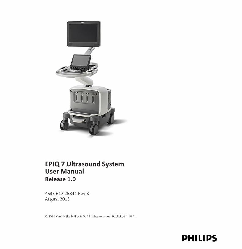
EPIQ 7 Ultrasound SystemUser ManualRelease 1.0
4535 617 25341 Rev B August 2013
© 2013 Koninklijke Philips N.V. All rights reserved. Published in USA.

Manufactured by Philips Ultrasound
22100 Bothell-Everett HighwayBothell, WA 98021-8431USATelephone: +1 425-487-7000 or 800-426-2670Fax: +1 425-485-6080www.healthcare.philips.com/ultrasound
This Medical Device meets the provisions of the transposition of the Medical Device Directive93/42/EEC within the country of origin of the Notified Body concerned with the device.
European Union Representative
Philips Medical Systems Nederland B.V.Quality & Regulatory AffairsVeenpluis 4-65684PC BestThe Netherlands
WARNINGUnited States federal law restricts this device to sale by or on the order of a physician. This document and the information contained in it is proprietary and confidential information of Philips Healthcare ("Philips") andmay not be reproduced, copied in whole or in part, adapted, modified, disclosed to others, or disseminated without the priorwritten permission of the Philips Legal Department. This document is intended to be used either by customers, and is licensed tothem as part of their Philips equipment purchase, or to meet regulatory commitments as required by the FDA under 21 CFR1020.30 (and any amendments to it) and other local regulatory requirements. Use of this document by unauthorized persons isstrictly prohibited.Philips provides this document without warranty of any kind, implied or expressed, including, but not limited to, the impliedwarranties of merchantability and fitness for a particular purpose.Philips has taken care to ensure the accuracy of this document. However, Philips assumes no liability for errors or omissions andreserves the right to make changes without further notice to any products herein to improve reliability, function, or design. Philipsmay make improvements or changes in the products or programs described in this document at any time.Unauthorized copying of this document, in addition to infringing copyright, might reduce the ability of Philips to provide accurateand current information to users.This product may contain remanufactured parts equivalent to new in performance, or parts that have had incidental use.This product and its accessories are manufactured under or operate in accordance with the following United States patents andcorresponding patents in other countries: U.S. Patent Numbers 5,469,851; 5,471,989; 5,482,045; 5,485,842; 5,577,505; 5,706,819;5,720,291; 5,735,281; 5,795,297; 5,833,613; 5,879,303; 5,891,040; 5,908,389; 5,951,478; 5,993,390; 5,993,392; 6,036,643;6,102,863; 6,126,599; 6,126,602; 6,210,328; 6,224,552; 6,231,510; 6,251,074; 6,283,919; 6,299,579; 6,306,089; 6,315,723;6,319,203; 6,364,828; 6,368,281; 6,380,766; 6,390,981; 6,416,477; 6,443,896; 6,447,453; 6,465,937; 6,469,957; 6,471,649;6,491,630; 6,497,660; 6,500,120; 6,516,215; 6,527,719; 6,527,721; 6,532,819; 6,540,684; 6,544,175; 6,544,177; 6,551,248;6,575,910; 6,629,929; 6,632,179; 6,676,606; 6,679,849; 6,685,637; 6,723,050; 6,743,174; 6,755,786; 6,755,788; 6,761,689;
2 EPIQ 7 User Manual 4535 617 25341

6,780,155; 6,824,517; 7,037,264; 7,043,062; 7,131,947; 7,439,656; 7,484,412; 7,544,164; 7,593,554; 7,637,869; 7,645,237;7,648,461; 7,656,418; 7,704,208; 7,758,508; 7,771,354; 7,859,170; 8,030,824; 8,038,618; 8,096,947; 8,137,272; 8,161,817;8,169,125; 8,177,718; 8,257,260; Re43,048; Re36,564."Chroma," "Color Power Angio," "High Q," "PercuNav," "QLAB," "SonoCT," "xMATRIX," and "XRES" are trademarks of KoninklijkePhilips N.V.Non-Philips product names may be trademarks of their respective owners.
EPIQ 7 User Manual 4535 617 25341 3

4 EPIQ 7 User Manual 4535 617 25341

Contents1 Read This First .............................................................................................................. 15 Intended Audience .............................................................................................................. 15 Intended Use ....................................................................................................................... 15 Warnings .............................................................................................................................. 16 Warning Symbols ................................................................................................................. 17 User Information Components ............................................................................................17 Product Conventions ........................................................................................................... 18 User Information Conventions ............................................................................................19 Upgrades and Updates ........................................................................................................ 21 Customer Comments ........................................................................................................... 21 Supplies and Accessories .....................................................................................................21 Customer Service ................................................................................................................. 22 Recycling, Reuse, and Disposal ............................................................................................222 Safety ........................................................................................................................... 27 Basic Safety .......................................................................................................................... 27 Electrical Safety ................................................................................................................... 29 Defibrillators ................................................................................................................33 Fire Safety ....................................................................................................................34 Mechanical Safety ................................................................................................................ 34 Equipment Protection .......................................................................................................... 36 Product Compatibility .......................................................................................................... 37 Symbols ................................................................................................................................ 38 Biological Safety ................................................................................................................... 46 FDA Medical Alert on Latex .........................................................................................49 ALARA Education Program ...........................................................................................50 Output Display .............................................................................................................54 Control Effects .............................................................................................................58 Related Guidance Documents .....................................................................................60 Acoustic Output and Measurement ............................................................................60 Acoustic Output Tables ................................................................................................63 Acoustic Measurement Precision and Uncertainty .....................................................63 Operator Safety ................................................................................................................... 65
Contents
EPIQ 7 User Manual 4535 617 25341 5
Repetitive Strain Injury ...............................................................................................65 Foot Switch Warning ...................................................................................................65 Philips Transducers ......................................................................................................66 Glutaraldehyde Exposure ............................................................................................66 Infection Control ..........................................................................................................66 Electromagnetic Compatibility ............................................................................................68 Radio-Frequency Emissions .........................................................................................69 ECG Signal ....................................................................................................................70 Electrostatic Discharge Precautions ............................................................................70 Electromagnetic Emissions ..........................................................................................71 Approved Cables for Electromagnetic Compliance .....................................................72 Approved Transducers for Electromagnetic Compliance ............................................73 Approved Accessories for Electromagnetic Compliance .............................................73 Electromagnetic Immunity ..........................................................................................74 Electromagnetic Interference ......................................................................................77 Recommended Separation Distance ...........................................................................79 Avoiding Electromagnetic Interference .......................................................................81 Use Restrictions Due to Interference ...........................................................................813 System Overview .......................................................................................................... 83 System Capabilities .............................................................................................................. 83 Measurements .............................................................................................................83 Transducer Types .........................................................................................................84 Image Acquisition and Review .....................................................................................84 Patient Data Protection ...............................................................................................84 System Options .................................................................................................................... 84 Imaging Options ...........................................................................................................85 Connectivity Capabilities .............................................................................................85 Clinical/Analysis Applications ......................................................................................86 QLAB Advanced Quantification Software Options .......................................................86 Stress Echocardiography ..............................................................................................87 Data Security ................................................................................................................88 PercuNav Image Fusion and Interventional Navigation ..............................................88 System Components ............................................................................................................ 88 Video Monitor ..............................................................................................................90 Control Module ............................................................................................................90
Contents
6 EPIQ 7 User Manual 4535 617 25341

On/Off (Power) Control ...............................................................................................92 Data Storage ...............................................................................................................93 Peripherals ...................................................................................................................95 Transducer Receptacles and Cable Management ........................................................96 Physio (ECG) Receptacles .............................................................................................98 Wheel Brakes and Steering Locks ................................................................................994 Preparing the System .................................................................................................. 101 Connecting Devices ............................................................................................................101 External Printers ........................................................................................................102 Connecting an External Printer ..................................................................................103 Configuring Local Printers ..........................................................................................104 Connecting the Foot Switch .......................................................................................105 Connecting an External DVD Recorder ......................................................................105 Connecting an External Color Monitor ......................................................................105 Connecting the System to a Network ................................................................................106 Moving the System ............................................................................................................ 106 Preparing and Moving the System .............................................................................108 Positioning the System in Confined Spaces ...............................................................111 Setting Up After Moving ............................................................................................1125 Using the System ........................................................................................................ 113 Turning the System On and Off .........................................................................................113 Setting the System Time and Date .....................................................................................114 Using the Brakes and Steering Locks .................................................................................115 Monitor Adjustments ........................................................................................................116 Positioning the Monitor .............................................................................................117 Changing the Monitor Tint .........................................................................................117 Changing the Default Monitor Brightness .................................................................118 Automatic Display Dimming ......................................................................................119 System Controls ................................................................................................................. 119 Control Panel .............................................................................................................119 Control Panel Adjustments ........................................................................................121 Adjusting Control Panel Brightness ...........................................................................121 Positioning the Control Panel ....................................................................................121 Setting the Depth Control ..........................................................................................122 Touch Screen .............................................................................................................122
Contents
EPIQ 7 User Manual 4535 617 25341 7

Touch Screen Layout ..................................................................................................123 Touch Screen Controls ...............................................................................................124 Utilities Touch Screen ................................................................................................125 System Tab Touch Screen Controls ............................................................................125 Trackball .....................................................................................................................126 Soft Key Controls .......................................................................................................127 Using the Keyboards ..................................................................................................128 Status Icons ................................................................................................................129 Power Management ..........................................................................................................130 Sleep Mode ................................................................................................................131 Battery Indicators ......................................................................................................132 System Security .................................................................................................................. 133 Logging On to the System ..........................................................................................133 Logging Off of the System ..........................................................................................134 Changing Your Password ...........................................................................................134 Imaging Display .................................................................................................................. 135 Patient Bar .................................................................................................................136 Image Area .................................................................................................................136 Tools and Icons Area ..................................................................................................138 Emergency Studies ............................................................................................................. 138 Temporary ID .............................................................................................................139 Starting Emergency Studies .......................................................................................139 Setting the Auto Freeze Function ......................................................................................140 Transducer Receptacles and Cable Management ..............................................................140 Selecting a Transducer .......................................................................................................142 Selecting a Preset ............................................................................................................... 143 ECG Feature ....................................................................................................................... 143 DVD, CD, and USB Devices .................................................................................................143 Media Compatibility ..................................................................................................143 DVD Drive ..................................................................................................................144 Loading and Ejecting a Disc ........................................................................................144 Erasing a DVD .............................................................................................................144 USB Devices ...............................................................................................................145 DICOM Viewer ...........................................................................................................1466 Customizing the System .............................................................................................. 147
Contents
8 EPIQ 7 User Manual 4535 617 25341

Presets ............................................................................................................................... 147 Setting the Default Transducer and Preset ................................................................148 Clinical Applications and Presets ...............................................................................148 Quick Save Presets .....................................................................................................148 Creating Quick Save Presets ......................................................................................149 Deleting Quick Save Presets ......................................................................................149 Copying Quick Save Presets to Removable Media .....................................................149 Loading Quick Save Presets from Removable Media .................................................150 System Setups .................................................................................................................... 150 Changing Setups ........................................................................................................151 Hiding the Doppler Velocity Minus Sign ....................................................................151 System Options .................................................................................................................. 152 Custom Procedures ............................................................................................................ 152 Creating a Custom Procedure ....................................................................................152 Selecting a Custom Procedure ...................................................................................1537 Performing an Exam .................................................................................................... 155 New Patient Exams ............................................................................................................ 155 Entering Patient Data .................................................................................................156 Selecting in the Worklist ............................................................................................156 Searching in the Worklist ...........................................................................................157 Hiding Patient Name and ID on Images .....................................................................157 Imaging Modes .................................................................................................................. 158 Selecting a Transducer .......................................................................................................158 Annotation ......................................................................................................................... 159 Adding Labels .............................................................................................................159 Adding Labels Using the Keyboard ............................................................................161 Adding an Image Title ................................................................................................161 Displaying Body Markers ...........................................................................................161 Recording ........................................................................................................................... 162 Using the DVD Recorder ............................................................................................162 Printing .............................................................................................................................. 163 Printing in Live Imaging ..............................................................................................163 Review ............................................................................................................................... 164 Starting Review ..........................................................................................................164 Navigating Thumbnails and Images ...........................................................................165
Contents
EPIQ 7 User Manual 4535 617 25341 9

Capturing Images and Loops ..............................................................................................165 Measurement and Analysis ...............................................................................................167 Performing a 2D Distance Measurement ..................................................................168 Measuring M-Mode Distance ....................................................................................169 Measuring the Doppler Trace on a Sweeping Display ...............................................169 Obtaining a Typical Labeled Measurement ...............................................................169 Measuring Then Labeling ...........................................................................................170 Ending an Exam .................................................................................................................. 1708 Transducers ................................................................................................................ 173 Selecting a Transducer .......................................................................................................173 Setting the Default Transducer and Preset ........................................................................174 Clinical Applications and Transducers ...............................................................................174 Indications for Use and Supporting Transducers ...............................................................176 xMatrix Array Transducers .................................................................................................177 X5-1 Description ........................................................................................................177 X6-1 Description ........................................................................................................178 Transducer Maintenance ...................................................................................................178 Acoustic Artifacts ............................................................................................................... 179 Acoustic Artifacts in 3D Imaging ................................................................................181 Transducer Covers ............................................................................................................. 183 Ultrasound Transmission Gels ...........................................................................................184 Transducer Storage ............................................................................................................ 185 Storage for Transport ................................................................................................185 Daily and Long-Term Storage .....................................................................................1869 Intraoperative Transducers ......................................................................................... 187 Operators of Intraoperative Transducers ..........................................................................187 Intended Uses for Intraoperative Transducers ..................................................................188 Patient Safety During Intraoperative Studies ...................................................................188 Patient-Contact Parts .................................................................................................189 Preventing Intraoperative Transducer Problems ..............................................................190 L15-7io Description ............................................................................................................190 Preparing Transducers for Intraoperative Use ..................................................................191 Disposable Drapes .....................................................................................................192 Accessories for Intraoperative Transducers ..............................................................192 Electrical Safety and Intraoperative Transducers ..............................................................192
Contents
10 EPIQ 7 User Manual 4535 617 25341

Leakage Current Testing for Intraoperative Transducers ..................................................193 Testing Intraoperative Transducer Leakage Current (Source) ...................................196 Testing Intraoperative Transducer Leakage Current (Sink) .......................................19710 Transesophageal Transducers ..................................................................................... 199 Operators of TEE Transducers ...........................................................................................199 Patient Safety During TEE Studies ......................................................................................200 Patient-Contact Parts .................................................................................................204 Preventing TEE Transducer Problems ................................................................................204 Electrical Safety and TEE Transducers ...............................................................................205 Leakage Current and TEE Transducers .......................................................................206 Reducing Risks of Using TEE Transducers ..................................................................206 TEE Deflection Control Basics ...........................................................................................207 X7-2t TEE Transducer Description .....................................................................................209 Using the X7-2t TEE Transducer .........................................................................................210 X7-2t Deflection Controls ..........................................................................................211 Manipulating the X7-2t Tip ........................................................................................213 Rotating the X7-2t Image Plane ................................................................................215 S7-3t TEE Transducer Description .....................................................................................216 Using the S7-3t TEE Transducer ........................................................................................217 S7-3t TEE Controls .....................................................................................................218 Manipulating the S7-3t TEE Tip ..................................................................................220 S7-3t TEE Array Rotation ...........................................................................................221 Rotating the S7-3t TEE Array .....................................................................................222 Checking the TEE Transducer .............................................................................................223 TEE Transducer Inspection .........................................................................................223 TEE Transducer Controls Inspection ..........................................................................223 Special Considerations for TEE Studies ..............................................................................223 Patient Selection for TEE Transducer Use ..................................................................224 Preparing Patients for TEE Studies ............................................................................225 TEE Study Guidelines .................................................................................................225 Tip Fold-Over ..................................................................................................................... 226 Recognizing Tip Fold-Over .........................................................................................226 Correcting Tip Fold-Over ............................................................................................227 Preventing Tip Fold-Over ..........................................................................................227 TEE Temperature Sensing ..................................................................................................228
Contents
EPIQ 7 User Manual 4535 617 25341 11

Ensuring Safe TEE Temperatures ...............................................................................229 Manual Auto-Cool Feature ........................................................................................229 Using the Temperature Display ................................................................................230 Patient Temperature .................................................................................................231 Entering Patient Temperature ...................................................................................231 Resuming Imaging After Auto-Cool ...........................................................................231 Patient Care After a TEE Study ...........................................................................................232 TEE Accessories and Supplies ............................................................................................233 Bite Guards ................................................................................................................233 TEE Transducer Covers ..............................................................................................233 Tip Protectors ............................................................................................................234 Disposable Drapes .....................................................................................................234 TEE Leakage Current Test ..................................................................................................234 TEE Test Background ..................................................................................................234 Testing TEE Transducer Leakage Current ...................................................................237 TEE Transducer References ...............................................................................................23811 Endocavity Transducers .............................................................................................. 239 Operators of Endocavity Transducers ................................................................................239 Patient Safety During Endocavity Studies ..........................................................................239 Preparing Transducers for Endocavity Use ........................................................................240 C10-3v Description .............................................................................................................241 C10-4ec Description ...........................................................................................................241 Patient-Contact Parts .........................................................................................................242 Biopsy with Endocavity Transducers .................................................................................24312 Biopsy Guides ............................................................................................................. 245 Attaching and Removing a Biopsy Guide ...........................................................................245 Biopsy Guideline Display ....................................................................................................246 Displaying the Biopsy Guideline .........................................................................................247 Moving the Biopsy Depth Cursor .......................................................................................248 Biopsy Guide Alignment ....................................................................................................249 Preparation for Alignment Verification .....................................................................249 Verifying the Biopsy Guide Alignment .......................................................................250 Performing a Biopsy Procedure .........................................................................................252 Biopsy Guide Maintenance ................................................................................................25413 Transducer Care .......................................................................................................... 255
Contents
12 EPIQ 7 User Manual 4535 617 25341

Transducer Care Safety ......................................................................................................255 Latex Product Alert ....................................................................................................256 Transmissible Spongiform Encephalopathy ...............................................................257 Choosing the Correct Transducer-Care Method ................................................................257 Transducer, Cable, and Connector Cleaning ......................................................................258 Cleaning a Transducer ...............................................................................................260 Cleaning and Disinfecting Cables and Connectors .....................................................261 Transducer Disinfection .....................................................................................................263 Isopropyl Alcohol Restrictions ...................................................................................264 Disinfecting Transducers Using a Wipe or Spray Method .........................................264 Transducer Disinfection by Immersion ......................................................................266 Minimizing the Effects of Residual Disinfectant ........................................................267 Disinfecting Non-TEE Transducers by Immersion ......................................................268 Cautions for TEE Transducer Disinfection ..................................................................269 Disinfecting TEE Transducers by Immersion ..............................................................270 Disinfecting TEE Transducers with an AER .................................................................273 Transducer Sterilization .....................................................................................................273 Sterilizing Transducers by Immersion ........................................................................275 Disinfectants Compatibility ................................................................................................276 Disinfectant Types .....................................................................................................277 Factors Affecting Disinfectant Efficiency ...................................................................278 Disinfectants and Cleaning Solutions Compatibility Table .........................................27814 System Maintenance .................................................................................................. 287 Cleaning and Maintaining the System ...............................................................................287 Cleaning the System and ECG Equipment .................................................................287 Disinfectants for System Surfaces .............................................................................289 Disinfecting System Surfaces .....................................................................................290 System Control Panel Maintenance ...........................................................................291 Cleaning the Trackball ................................................................................................291 Cleaning the System Air Filter ....................................................................................291 Specifying and Resetting the Air Filter Maintenance Status ......................................293 Transducer Maintenance ...................................................................................................293 Printer and DVD Recorder Maintenance ...........................................................................294 Troubleshooting ................................................................................................................. 295 Error Messages .................................................................................................................. 296
Contents
EPIQ 7 User Manual 4535 617 25341 13
Test Patterns ...................................................................................................................... 296 Transferring the Test Patterns ...................................................................................296 Using the Test Patterns ..............................................................................................296 Testing the System .............................................................................................................297 For Assistance .................................................................................................................... 29715 Specifications .............................................................................................................. 299 Safety and Regulatory Requirements ................................................................................30216 Index .......................................................................................................................... 303
Contents
14 EPIQ 7 User Manual 4535 617 25341
Read This FirstThis manual is intended to assist you with the safe and effective operation of your Philipsproduct. Before attempting to operate the product, read this manual and strictly observe allwarnings and cautions. Pay special attention to the information in the “Safety” section.
The user information for your Philips product describes the most extensive configuration of theproduct, with the maximum number of options and accessories. Some functions described maybe unavailable on your product's configuration.
Intended AudienceBefore you use your user information, you need to be familiar with ultrasound techniques.Sonography training and clinical procedures are not included here.
This document is intended for sonographers, physicians, and biomedical engineers who operateand maintain your Philips product.
Intended UseThis product is intended to be installed, used, and operated only in accordance with the safetyprocedures and operating instructions given in the product user information, and only for thepurposes for which it was designed. For indications for use, see “Indications for Use andSupporting Transducers” on page 176. However, nothing stated in the user informationreduces your responsibility for sound clinical judgment and best clinical procedure.
Installation, use, and operation of this product is subject to the law in the jurisdictions in whichthe product is used. Install, use, and operate the product only in such ways that do not conflictwith applicable laws or regulations, which have the force of law.
Use of the product for purposes other than those intended and expressly stated by Philips, aswell as incorrect use or operation, may relieve Philips or its agents from all or someresponsibility for resultant noncompliance, damage, or injury.
1
Intended Audience Read This First
EPIQ 7 User Manual 4535 617 25341 15
WARNINGSystem users are responsible for image quality and diagnosis. Inspect the data that is beingused for the analysis and diagnosis and ensure that the data is sufficient both spatially andtemporally for the measurement approach being used.
WarningsBefore using the system, read these warnings and the “Safety” section.
WARNINGDo not remove the protective covers on the system; hazardous voltages are present inside.Cabinet panels must be in place while the system is in use. All internal adjustments andreplacements must be made by a qualified Philips Ultrasound field service engineer.
WARNINGTo avoid electrical shock, use only supplied power cords and connect only to properlygrounded wall (wall/mains) outlets.
WARNINGDo not operate this system in the presence of flammable gases or anesthetics. Explosion canresult. The system is not compliant in AP/APG environments as defined by IEC 60601-1.
WARNINGMedical equipment must be installed and put into service according to the specialelectromagnetic compatibility (EMC) guidelines provided in the “Safety” section.
WARNINGThe use of portable and mobile radio-frequency (RF) communications equipment can affectthe operation of medical equipment.
Read This First Warnings
16 EPIQ 7 User Manual 4535 617 25341
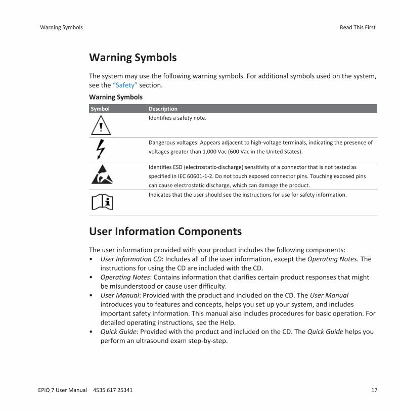
Warning SymbolsThe system may use the following warning symbols. For additional symbols used on the system,see the “Safety” section.
Warning SymbolsSymbol Description
Identifies a safety note.
Dangerous voltages: Appears adjacent to high-voltage terminals, indicating the presence ofvoltages greater than 1,000 Vac (600 Vac in the United States).
Identifies ESD (electrostatic-discharge) sensitivity of a connector that is not tested asspecified in IEC 60601-1-2. Do not touch exposed connector pins. Touching exposed pinscan cause electrostatic discharge, which can damage the product.Indicates that the user should see the instructions for use for safety information.
User Information ComponentsThe user information provided with your product includes the following components:• User Information CD: Includes all of the user information, except the Operating Notes. The
instructions for using the CD are included with the CD.• Operating Notes: Contains information that clarifies certain product responses that might
be misunderstood or cause user difficulty.• User Manual: Provided with the product and included on the CD. The User Manual
introduces you to features and concepts, helps you set up your system, and includesimportant safety information. This manual also includes procedures for basic operation. Fordetailed operating instructions, see the Help.
• Quick Guide: Provided with the product and included on the CD. The Quick Guide helps youperform an ultrasound exam step-by-step.
Warning Symbols Read This First
EPIQ 7 User Manual 4535 617 25341 17
• Help: Available on the system in some languages and included on the CD, the Help containscomprehensive instructions for using the system. The Help also provides referenceinformation and descriptions of all controls and display elements. To display the Help, touch
on the touch screen.• Acoustic Output Tables: Included on the CD, it contains information about acoustic output
and patient-applied part temperatures.• Medical Ultrasound Safety: Included on the CD, it contains information on bioeffects and
biophysics, prudent use, and implementing ALARA (as low as reasonably achievable).• Shared Roles for System and Data Security: Included on the CD, it contains guidelines to
help you understand how the security of your Philips product could be compromised andinformation on Philips' efforts to help you prevent security breaches.
• Media Compatibility: Included on the CD, it contains current information on media that arecompatible with your system.
Product ConventionsYour Philips product uses certain conventions throughout the interface to make it easy for youto learn and use:• Three unlabeled buttons near the trackball are used with the trackball. The two buttons on
either side of the trackball are called the "left and right trackball buttons," and they operatesomewhat similarly to PC mouse buttons. The button above the trackball is called the"middle trackball button," and it is used to update the imaging display, completemeasurements, and other operations as specified in procedures. The trackball arbitrationicon, at the bottom of the display, indicates the current functions of the trackball buttons.
• Tabs along the top of the monitor display let you choose additional sets of setup options.Tabs along the top of the touch screen let you choose additional pages of controls.
• To type text into a text field, click in the field and use the keyboard.
• To display a list, click the down arrow . To scroll through a list, click the arrows at eitherend of the scroll bar or drag the scroll box up or down.
• Controls on the control panel include buttons, knobs, slide controls, and a trackball. Press abutton to activate or deactivate its function. Turn a knob to change the selected setting.Press a knob-button to activate its function, or turn it to change the selected setting. Movea slide control to change its setting. Roll the trackball in the direction that you want to movean object.
Read This First Product Conventions
18 EPIQ 7 User Manual 4535 617 25341
• Controls on the touch screen include buttons, knob labels, and sliders. To use a touchscreen button, simply touch it. To use a touch screen knob label, touch the label and adjustthe corresponding knob, located directly below it on the control panel. If two knob labelsare available for the knob, you must first touch the knob label that you want to adjust. Touse a slider, swipe the slider button, or touch a location on the slider, to move the sliderbutton.
• Many tabs on the touch screen contain two pages of controls. To display the second page,place your finger on the touch screen and swipe to the left. To return to the first page, placeyour finger on the touch screen and swipe to the right.
• Some areas of the display include chevrons . Clicking displays or hides additionalinformation, options, or fields.
User Information ConventionsThe user information for your product uses the following typographical conventions to assistyou in finding and understanding information: • All procedures are numbered, and all subprocedures are lettered. You must complete steps
in the sequence they are presented to ensure success.• Bulleted lists indicate general information about a particular function or procedure. They do
not imply a sequential procedure.• Control names and menu items or titles are spelled as they are on the system, and they
appear in bold text. Exceptions are the trackball, the buttons adjacent to it, and the TGCslide controls, all of which are unlabeled.
• Symbols appear as they appear on the system.• The pointer is the cursor used to select elements on the display. Use the Pointer control to
display the pointer.• Point means to position the tip of the pointer or cursor on an item on the display.• Click means to move the pointer or cursor to an object and press one of the unlabeled
trackball buttons located on either side of the trackball.• Select means to move the pointer to an object and press one of the unlabeled trackball
buttons located on either side of the trackball to "highlight" the object (such as an item in alist), or in the case of a check box or "radio button," to fill the object. Deselect meansclicking the item to remove the highlight or fill.
• Double-click means to quickly click twice to select an object or text.
User Information Conventions Read This First
EPIQ 7 User Manual 4535 617 25341 19
• Drag means to place the pointer over an object and then press and hold the left or righttrackball button while moving the trackball. Use this method to move an object on thedisplay.
• Touch means to press a button on the touch screen, located above the control panel.• Swipe means to touch the touch screen with the tip of your finger and move your finger in a
quick motion either to the left or to the right. This action displays an additional touchscreen, if one is available.
• Highlight means to change the color of a display selection (such as an item in a list) oroverlay it with a colored bar, usually by clicking.
• The left side of the system is to your left as you stand in front of the system, facing thesystem. The front of the system is nearest to you as you operate it.
• Transducers and pencil probes both are referred to as transducers, unless the distinction isimportant to the meaning of the text.
Information that is essential for the safe and effective use of your product appears throughoutyour user information as follows:
WARNINGWarnings highlight information vital to the safety of you, the operator, and the patient.
CAUTIONCautions highlight ways that you could damage the product and consequently void yourwarranty or service contract or ways that you could lose patient or system data.
NOTENotes bring your attention to important information that will help you operate the productmore effectively.
Read This First User Information Conventions
20 EPIQ 7 User Manual 4535 617 25341
Upgrades and UpdatesPhilips is committed to innovation and continued improvement. Upgrades may be announcedthat consist of hardware or software improvements. Updated user information will accompanythose upgrades.
Customer CommentsIf you have questions about the user information, or you discover an error in the userinformation, in the USA, please call Philips at 800-722-9377; outside the USA, please call yourlocal customer service representative.
Supplies and AccessoriesTo order ECG trunk cables, lead sets, and electrodes; transducer covers; bite guards; biopsyguides; and other supplies and accessories, contact CIVCO Medical Solutions:
CIVCO Medical Solutions
102 First Street South, Kalona, IA 52247‑9589
Telephone: 800‑445‑6741 (USA and Canada), +1 319‑248‑6757 (International)
Fax: 877‑329‑2482 (USA and Canada), +1 319‑248‑6660 (International)
E-mail: [email protected]
Internet: www.civco.com
To order the items listed in the following table, see the referenced section and then contactyour Philips representative.
System Accessories
Item Additional Information
Cables See “Approved Cables for Electromagnetic Compliance” onpage 72.
DVD recorder See “Approved Accessories for ElectromagneticCompliance” on page 73
Upgrades and Updates Read This First
EPIQ 7 User Manual 4535 617 25341 21
Item Additional Information
Foot switch Contact your Philips representative.
Printers See “External Printers” on page 102.
Removable media See “Media Compatibility” on page 143.
Transducers See “Clinical Applications and Transducers” on page 174.
Customer ServiceCustomer service representatives are available worldwide to answer questions and to providemaintenance and service. Please contact your local Philips representative for assistance. Youcan also contact the following office for referral to a customer service representative, or visitthe Philips Healthcare "Contact Us" website:
www.healthcare.philips.com/main/about/officelocator/index.wpd
Philips Ultrasound Headquarters
22100 Bothell-Everett Highway, Bothell, WA 98021-8431, USA
800-722-9377
Recycling, Reuse, and DisposalPhilips is concerned with helping protect the natural environment and helping ensurecontinued safe and effective use of this system through proper support, maintenance, andtraining. Philips designs and manufactures equipment in compliance with relevant guidelinesfor environmental protection. As long as the equipment is properly operated and maintained, itpresents no risk to the environment. However, the equipment may contain materials that couldbe harmful to the environment if disposed of incorrectly. Use of such materials is essential forthe implementation of certain functions and for meeting certain statutory and otherrequirements.
The European Union Directive on Waste Electrical and Electronic Equipment (WEEE) requiresproducers of electrical and electronic equipment to provide reuse and treatment informationfor each product. This information is provided in a Philips Healthcare Recycling Passport. Suchrecycling passports for Philips Ultrasound systems are available on this website:
Read This First Customer Service
22 EPIQ 7 User Manual 4535 617 25341
www.healthcare.philips.com/main/about/sustainability/recycling/ultrasound.wpd
Recycling, reuse, and disposal information in this document is directed mainly at the entity withlegal authority over the equipment. Operators are usually uninvolved in disposal, except in thecase of certain batteries.
Passing Your System to Another User
If you pass this system to another user who will use the system for its intended purpose, thenpass it on in its complete state. Particularly, ensure that all the product-support documentation,including all instructions for use, are passed on to the new user. Make the new user aware ofthe support services that Philips Healthcare provides for installing, commissioning, andmaintaining the system, and for comprehensive operator training. Existing users mustremember that passing on medical electrical equipment to new users may present serioustechnical, medical, privacy, and legal risks. The original user may remain liable, even if theequipment is given away.
Philips strongly advises you to seek advice from your local Philips representative beforeagreeing to pass on any equipment.
After you pass the system to a new user, you might still receive important safety-relatedinformation, such as bulletins and field change orders. In many jurisdictions the original ownerhas a clear duty to communicate such safety-related information to new users. If you areunable or unprepared to do this, inform Philips Healthcare about the new user, so that PhilipsHealthcare can provide the new user with safety-related information.
Final Disposal of Your System
Final disposal is when you dispose of the system in such a way that it can no longer be used forits intended purposes.
Recycling, Reuse, and Disposal Read This First
EPIQ 7 User Manual 4535 617 25341 23
WARNINGDo not dispose of this system (or any parts of it) with industrial or domestic waste. Thesystem may contain materials such as lead, tungsten, or oil, or other hazardous substancesthat can cause serious environmental pollution. The system also contains privacy-sensitiveinformation, which should be properly removed (scrubbed). Philips advises you to contactyour Philips service organization before disposing of this system.
Philips Healthcare gives support for the following:• Recovery of useful parts• Recycling of useful materials by competent disposal companies• Safe and effective disposal of equipment
For advice and information, contact your Philips service organization, or see the followingwebsite:
www.healthcare.philips.com/us/about/sustainability/recycling
Perchlorate Material
In this system, perchlorate material is present in lithium coin cells or batteries. Special handlingmay apply to those items. For more information, see this website:
www.dtsc.ca.gov/hazardouswaste/perchlorate
Discarding Batteries
Batteries should be discarded if there are visual signs of damage. Batteries should be discardedin an environmentally safe manner. Properly dispose of batteries according to local regulations.
WARNINGDo not disassemble, puncture, or incinerate batteries. Be careful not to short the batteryterminals because this could result in a fire hazard.
Read This First Recycling, Reuse, and Disposal
24 EPIQ 7 User Manual 4535 617 25341

CAUTIONUse caution when handling, using, and testing the batteries. Do not short circuit, crush, drop,mutilate, puncture, apply reverse polarity, expose to high temperatures, or disassemble.Misuse or abuse could cause physical injury.
NOTEWash skin with large amounts of water in the event of electrolyte leakage to prevent skinirritation and inflammation.
Recycling, Reuse, and Disposal Read This First
EPIQ 7 User Manual 4535 617 25341 25

Read This First Recycling, Reuse, and Disposal
26 EPIQ 7 User Manual 4535 617 25341
SafetyPlease read this information before using your ultrasound system. It applies to the ultrasoundsystem, transducers, recording devices, and any optional equipment. This section coversgeneral safety information only. Safety information that applies only to a specific task isincluded in the procedure for that task.
This device is intended for use by, or by the order of, and under the supervision of a licensedphysician qualified to direct the use of the device.
WARNINGWarnings highlight information vital to the safety of you, the operator, and the patient.
CAUTIONCautions highlight ways that you could damage the product and consequently void yourwarranty or service contract or ways that you could lose patient or system data.
Basic Safety
WARNINGDo not use the system for any application until you have read, understood, and know all thesafety information, safety procedures, and emergency procedures contained in this "Safety"section. Operating the system without a proper awareness of safe use could lead to fatal orother serious personal injury.
2
Basic Safety Safety
EPIQ 7 User Manual 4535 617 25341 27
WARNINGDo not use this system for any application until you are sure that the system's periodicmaintenance is current. If any part of the system is known or suspected to be defective orincorrectly adjusted, do not use the system until it is repaired. Operating the system withdefective or incorrectly adjusted components could expose you and the patient to safetyhazards.
WARNINGDo not use the system for any application until you are adequately and properly trained onits safe and effective operation. If you are unsure of your ability to operate the system safelyand effectively, do not use it. Operation of the system without proper and adequate trainingcould lead to fatal or other serious personal injury.
WARNINGDo not operate the system with patients unless you have an adequate understanding of itscapabilities and functions. Using the system without such understanding may compromisethe system's effectiveness and the safety of the patient, you, and others.
WARNINGNever attempt to remove, modify, override, or frustrate any safety device on the system.Interfering with safety devices could lead to fatal or other serious personal injury.
WARNINGUse the system only for its intended purposes. Do not use the system with any product thatPhilips does not recognize as compatible with the system. Operation of the product forunintended purposes, or with incompatible products, could lead to fatal or other seriousinjury.
WARNINGStop use immediately if the system or the transducer appear to be malfunctioning. Contactyour Philips representative immediately.
Safety Basic Safety
28 EPIQ 7 User Manual 4535 617 25341
Electrical SafetyThis equipment has been verified by a recognized third-party testing agency as a Class I devicewith Type BF and Type CF isolated patient-applied parts. (The safety standards met by thissystem are included in the “Specifications” section.) For maximum safety, observe thesewarnings and cautions:
WARNINGShock hazards may exist if this system, including all externally mounted recording andmonitoring devices, is not properly grounded. Protection against electrical shock is providedby grounding the chassis with a three-wire cable and plug. The system must be plugged into agrounded outlet. The grounding wire must not be removed or defeated.
WARNINGTo avoid the risk of electrical shock, never connect the system power cord to a power strip oran extension cord. When using the power cord, always connect it directly to a grounded walloutlet.
WARNINGUse only Type CF transducers for invasive procedures. Type B transducers are insufficientlyelectrically isolated for invasive use.
WARNINGDo not remove the protective covers on the system; hazardous voltages are present inside.Cabinet panels must be in place while the system is in use. All internal adjustments andreplacements must be made by a qualified Philips Ultrasound field service engineer.
WARNINGDo not operate this system in the presence of flammable gases or anesthetics. Explosion canresult. The system is not compliant in AP/APG environments as defined by IEC 60601-1.
Electrical Safety Safety
EPIQ 7 User Manual 4535 617 25341 29
WARNINGTo avoid risk of electrical shock hazards, always inspect the transducer before use: Check theface, housing, and cable before use. Do not use if the face is cracked, chipped, or torn; thehousing is damaged; or the cable is abraded.
WARNINGTo avoid risk of electrical shock hazards, always turn off the system and disconnect it fromthe wall outlet before cleaning the system.
WARNINGAll patient-contact devices, such as transducers, pencil probes, and ECG leads not specificallyindicated as defibrillation-proof, must be removed from patient contact before application ofa high-voltage defibrillation pulse. See “Defibrillators” on page 33.
WARNINGDuring transesophageal echocardiographic (TEE) procedures, either remove the TEEtransducer from the patient or disconnect the TEE transducer from the system immediatelyfollowing image acquisition.
WARNINGUltrasound equipment in normal operation, as with other medical electronic diagnosticequipment, uses high-frequency electrical signals that can interfere with pacemakeroperation. Though the possibility of interference is slight, be alert to this potential hazard andstop system operation immediately if you note interference with a pacemaker.
WARNINGWhen using additional peripheral equipment powered from an electrical source other thanthe ultrasound system, the combination is considered to be a medical system. It is yourresponsibility to comply with IEC 60601-1 and test the system to those requirements. If youhave questions, contact your Philips representative.
Safety Electrical Safety
30 EPIQ 7 User Manual 4535 617 25341
WARNINGDo not use nonmedical peripherals, such as report printers, within 1.5 m (5 ft) of a patient,unless the nonmedical peripherals receive power from an isolated power outlet on the Philipsultrasound system, or from an isolation transformer that meets medical safety standards, asdefined by standard IEC 60601-1.
WARNINGThe system and patient-applied parts meet the standard IEC 60601-1. Applied voltagesexceeding the standard, although unlikely, may result in electrical shock to the patient oroperator.
WARNINGConnection of optional devices not supplied by Philips Ultrasound could result in electricalshock. When such optional devices are connected to your ultrasound system, ensure that thetotal system earth leakage current does not exceed 500 µA.
WARNINGTo avoid risk of electrical shock, do not use any transducer that has been immersed beyondthe specified cleaning or disinfection level.
WARNINGTo avoid risks of electrical shock and fire hazards, inspect the system power cord and plugregularly. Ensure that they are not damaged in any way.
WARNINGDo not drape the power cord over any of the cable hooks or the handle on the system cart.Damage to the cord or power receptacle unit can occur if the cart is raised.
WARNINGOperating the system with physio input signals that are below the specified minimum levelsmay cause inaccurate results. See the “Specifications” section.
Electrical Safety Safety
EPIQ 7 User Manual 4535 617 25341 31
WARNINGElectrosurgical units (ESUs) and other devices intentionally introduce radio frequencyelectromagnetic fields or currents into patients. Because imaging ultrasound frequencies arecoincidentally in the radio frequency range, ultrasound transducer circuits are susceptible toradio frequency interference. While an ESU is in use, severe noise interferes with the black-and-white image and completely obliterates the color image. Concurrent failures in an ESU orother device and in the outer layer of the TEE transducer shaft can cause electrosurgicalcurrents to return along the transducer conductors. This could burn the patient, and theultrasound system and the transducer could also be damaged. Be aware that a disposabletransducer cover provides no protective electrical insulation at ESU frequencies.
WARNINGTo avoid risk of a burn hazard, do not use transducers with high-frequency surgicalequipment. A burn hazard may result from a defect in the high-frequency surgical neutralelectrode connection.
WARNINGUsing cables, transducers, and accessories other than those specified for use with the systemmay result in increased emissions from, or decreased immunity of, the system.
CAUTIONAlthough your system has been manufactured in compliance with existing EMI/EMCrequirements, use of this system in the presence of an electromagnetic field can causemomentary degradation of the ultrasound image. When interference is present orintermittent, use caution when continuing to use the system. If interference occurs often,review the environment in which the system is being used, to identify possible sources ofradiated emissions. These emissions could be from other electrical devices used within thesame room or an adjacent room. Communication devices such as cellular phones and pagerscan cause these emissions. The existence of radio, TV, or microwave transmission equipmentlocated nearby can cause emissions. In cases where EMI is causing disturbances, it may benecessary to relocate your system.
Safety Electrical Safety
32 EPIQ 7 User Manual 4535 617 25341
CAUTIONFor information on electromagnetic emissions and immunity as it applies to the system, see“Electromagnetic Compatibility ” on page 68. Ensure that the operating environment ofyour system meets the conditions specified in the referenced information. Operating thesystem in an environment that does not meet those conditions may degrade systemperformance.
DefibrillatorsObserve the following warnings when a defibrillation is required while using the ultrasoundsystem.
WARNINGBefore defibrillation, always remove all patient-applied parts from the patient.
WARNINGBefore defibrillation, always disconnect invasive transducers that remain in contact with thepatient from the system.
WARNINGA disposable transducer cover provides no protective electrical insulation againstdefibrillation.
WARNINGA small hole in the outer layer of the transducer opens a conductive path to grounded metalparts of the transducer. The secondary arcing that could occur during defibrillation couldcause patient burns. The risk of burns is reduced, but not eliminated, by using an ungroundeddefibrillator.
Electrical Safety Safety
EPIQ 7 User Manual 4535 617 25341 33
Use defibrillators that do not have grounded patient circuits. To determine whether adefibrillator patient circuit is grounded, see the defibrillator service guide, or consult abiomedical engineer.
Fire Safety
WARNINGOn electrical or chemical fires, use only extinguishers that are specifically labeled for thosepurposes. Using water or other liquids on an electrical fire can lead to fatal or other seriouspersonal injury. Before attempting to fight a fire, if it is safe to do so, attempt to isolate theproduct from electrical and other supplies, to reduce the risk of electrical shock.
Use of electrical products in an environment for which they were not designed can lead to fireor explosion. Fire regulations for the type of medical area being used should be fully applied,observed, and enforced. Fire extinguishers should be available for both electrical andnonelectrical fires.
Mechanical SafetyA list of precautions related to mechanical safety follows; observe these precautions whenusing the system:
WARNINGBe aware of the wheels on the system cart, especially when moving the system. The systemcould cause injury to you or others if it rolls over feet or into shins. Use caution when goingup or down ramps.
WARNINGWhen attempting to overcome an obstacle, do not push the system from either side withexcessive force, which could cause the system to tip over.
Safety Electrical Safety
34 EPIQ 7 User Manual 4535 617 25341
WARNINGPosition external hardcopy devices away from the system. Ensure that they are secure. Donot stack them on the system.
WARNINGWhen positioning the monitor, move it carefully to avoid pinching hands or extremitiesagainst other objects, such as a bed rail.
WARNINGNever park the system on an incline.
WARNINGThe brakes are intended as a convenience. To increase cart security, use wheel chocks whenthe system is parked.
WARNINGIf system operation is abnormal after you move or transport the system, contact PhilipsUltrasound Customer Service immediately. System components are installed securely and canwithstand considerable shock, but excessive shock can cause a system failure.
WARNINGTo avoid injury, Philips recommends against lifting the system cart.
WARNINGIf you park the system on a floor that is tilted 10 degrees or more and set the brakes, one ofthe braked casters might not be touching the floor, which can cause the system to move.
Mechanical Safety Safety
EPIQ 7 User Manual 4535 617 25341 35
WARNINGBefore moving the system, ensure that the keyboard is retracted, the control panel iscentered, and the monitor is locked. When extended, the keyboard might be damaged if ithits another object, and the video monitor could swing out during transport, causing injury orequipment damage.
CAUTIONEnsure that the cables for all patient-applied parts are secure before moving the system. Usethe cable management system to ensure that transducer cables are protected from damage.
CAUTIONDo not roll the system over transducer cables or power cables.
Equipment ProtectionFollow these precautions to protect your system:
CAUTIONExcessive bending or twisting of cables on patient-applied parts may cause failure orintermittent operation of the system. Do not roll the system over cables, which may damagethem.
CAUTIONImproper cleaning or sterilization of a patient-applied part may cause permanent damage.For cleaning and disinfection instructions, see the “Transducer Care” section.
CAUTIONDo not submerge the transducer connector in solution. The cables and transducer bodies areliquid‑tight, but the connectors are not.
Safety Equipment Protection
36 EPIQ 7 User Manual 4535 617 25341
CAUTIONDo not use solvents, such as thinner or acetone, or abrasive cleaners on the system,transducers, or any hardcopy device.
CAUTIONFor optimal performance, connect your ultrasound system to a circuit dedicated solely for thesystem. Do not connect life-support devices to the same circuit as the ultrasound system.
CAUTIONIf systems, transducers, and peripherals have been in an environment below 10°C (50°F),allow them to reach room temperature before connecting or turning them on. Philipsrecommends allowing 24 hours for complete normalization. Otherwise, condensation insidethe devices could cause damage. If the device was only briefly exposed to temperaturesbelow 10°C (50°F), then the time required for the device to return to room temperature couldbe significantly less than 24 hours.
CAUTIONTo avoid damaging the flat-panel display in the monitor, do not store the system where theambient temperature exceeds 65°C (149°F).
Product CompatibilityDo not use your system in combination with other products or components, unless Philipsexpressly recognizes those other products or components as compatible. For information aboutsuch products and components, contact your Philips representative.
Changes and additions to the system should be made only by Philips or by third partiesexpressly authorized by Philips to do so. Such changes and additions must comply with allapplicable laws and regulations that have the force of law within the jurisdictions concerned,and best engineering practices.
Product Compatibility Safety
EPIQ 7 User Manual 4535 617 25341 37

WARNINGSystem changes and additions that are made without the appropriate training or by usingunapproved spare parts may void the Philips warranty. As with all complex technicalproducts, maintenance by unqualified persons or using unapproved spare parts carriesserious risks of system damage and personal injury.
SymbolsThe International Electrotechnical Commission (IEC) has established a set of symbols formedical electronic equipment that classify a connection or warn of potential hazards. Of thosesymbols, the following may be used on your Philips product and its accessories and packaging.
USA federal law restricts this device to sale by or on the order of a physician.
Isolated patient connection (Type BF applied part).
Defibrillation-proof patient connection (Type BF applied part).
Non-isolated patient connection (Type B applied part).
Isolated patient connection for applied part intended for intraoperative use,including direct cardiac application and contact with major vessels (Type CFapplied part).
Defibrillation-proof patient connection (Type CF applied part).
Safety Symbols
38 EPIQ 7 User Manual 4535 617 25341
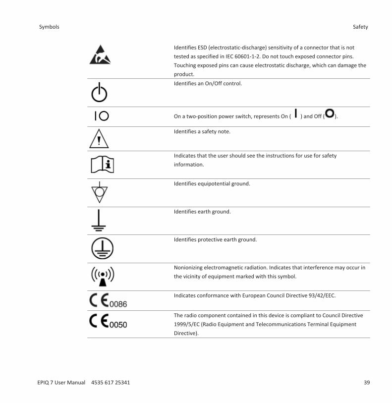
Identifies ESD (electrostatic-discharge) sensitivity of a connector that is nottested as specified in IEC 60601-1-2. Do not touch exposed connector pins.Touching exposed pins can cause electrostatic discharge, which can damage theproduct.Identifies an On/Off control.
On a two-position power switch, represents On ( ) and Off ( ).
Identifies a safety note.
Indicates that the user should see the instructions for use for safetyinformation.
Identifies equipotential ground.
Identifies earth ground.
Identifies protective earth ground.
Nonionizing electromagnetic radiation. Indicates that interference may occur inthe vicinity of equipment marked with this symbol.
Indicates conformance with European Council Directive 93/42/EEC.
The radio component contained in this device is compliant to Council Directive1999/5/EC (Radio Equipment and Telecommunications Terminal EquipmentDirective).
Symbols Safety
EPIQ 7 User Manual 4535 617 25341 39
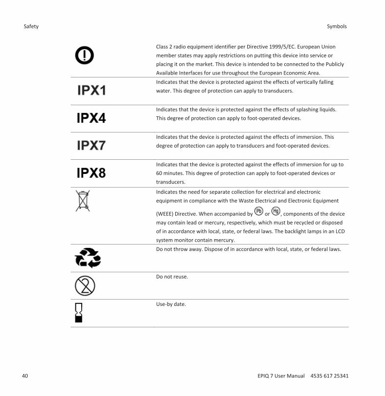
Class 2 radio equipment identifier per Directive 1999/5/EC. European Unionmember states may apply restrictions on putting this device into service orplacing it on the market. This device is intended to be connected to the PubliclyAvailable Interfaces for use throughout the European Economic Area.Indicates that the device is protected against the effects of vertically fallingwater. This degree of protection can apply to transducers.
Indicates that the device is protected against the effects of splashing liquids.This degree of protection can apply to foot-operated devices.
Indicates that the device is protected against the effects of immersion. Thisdegree of protection can apply to transducers and foot-operated devices.
Indicates that the device is protected against the effects of immersion for up to60 minutes. This degree of protection can apply to foot-operated devices ortransducers.
Indicates the need for separate collection for electrical and electronicequipment in compliance with the Waste Electrical and Electronic Equipment
(WEEE) Directive. When accompanied by or , components of the devicemay contain lead or mercury, respectively, which must be recycled or disposedof in accordance with local, state, or federal laws. The backlight lamps in an LCDsystem monitor contain mercury.Do not throw away. Dispose of in accordance with local, state, or federal laws.
Do not reuse.
Use-by date.
Safety Symbols
40 EPIQ 7 User Manual 4535 617 25341
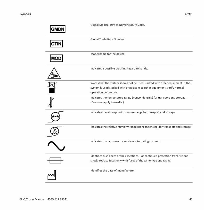
Global Medical Device Nomenclature Code.
Global Trade Item Number
Model name for the device
Indicates a possible crushing hazard to hands.
Warns that the system should not be used stacked with other equipment. If thesystem is used stacked with or adjacent to other equipment, verify normaloperation before use.
Indicates the temperature range (noncondensing) for transport and storage.(Does not apply to media.)
Indicates the atmospheric pressure range for transport and storage.
Indicates the relative humidity range (noncondensing) for transport and storage.
Indicates that a connector receives alternating current.
Identifies fuse boxes or their locations. For continued protection from fire andshock, replace fuses only with fuses of the same type and rating.
Identifies the date of manufacture.
Symbols Safety
EPIQ 7 User Manual 4535 617 25341 41

Identifies the legal manufacturer.
This side up: Points toward the side of the shipping crate that should be keptfacing up.
Indicates that the device should be kept dry.
Indicates that the device is fragile; handle with care.
Do not use if damaged.
Warns of system over-balance due to external force. (Do not push on themonitor or the transducer holders to move the system.)
Keep away from sunlight.
Non-sterile.
Sterilized using ethylene oxide.
Catalog number.
Batch code.
Safety Symbols
42 EPIQ 7 User Manual 4535 617 25341
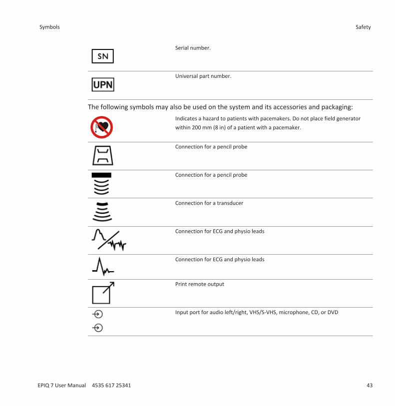
Serial number.
Universal part number.
The following symbols may also be used on the system and its accessories and packaging:Indicates a hazard to patients with pacemakers. Do not place field generatorwithin 200 mm (8 in) of a patient with a pacemaker.
Connection for a pencil probe
Connection for a pencil probe
Connection for a transducer
Connection for ECG and physio leads
Connection for ECG and physio leads
Print remote output
Input port for audio left/right, VHS/S-VHS, microphone, CD, or DVD
Symbols Safety
EPIQ 7 User Manual 4535 617 25341 43
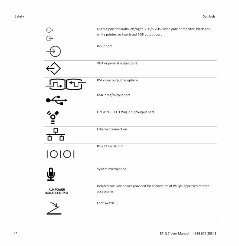
Output port for audio left/right, VHS/S-VHS, video patient monitor, black-and-white printer, or interlaced RGB output port
Input port
VGA or parallel output port
DVI video output receptacle
USB input/output port
FireWire (IEEE 1394) input/output port
Ethernet connection
RS-232 serial port
System microphone
Isolated auxiliary power provided for connection of Philips-approved remoteaccessories.
Foot switch
Safety Symbols
44 EPIQ 7 User Manual 4535 617 25341
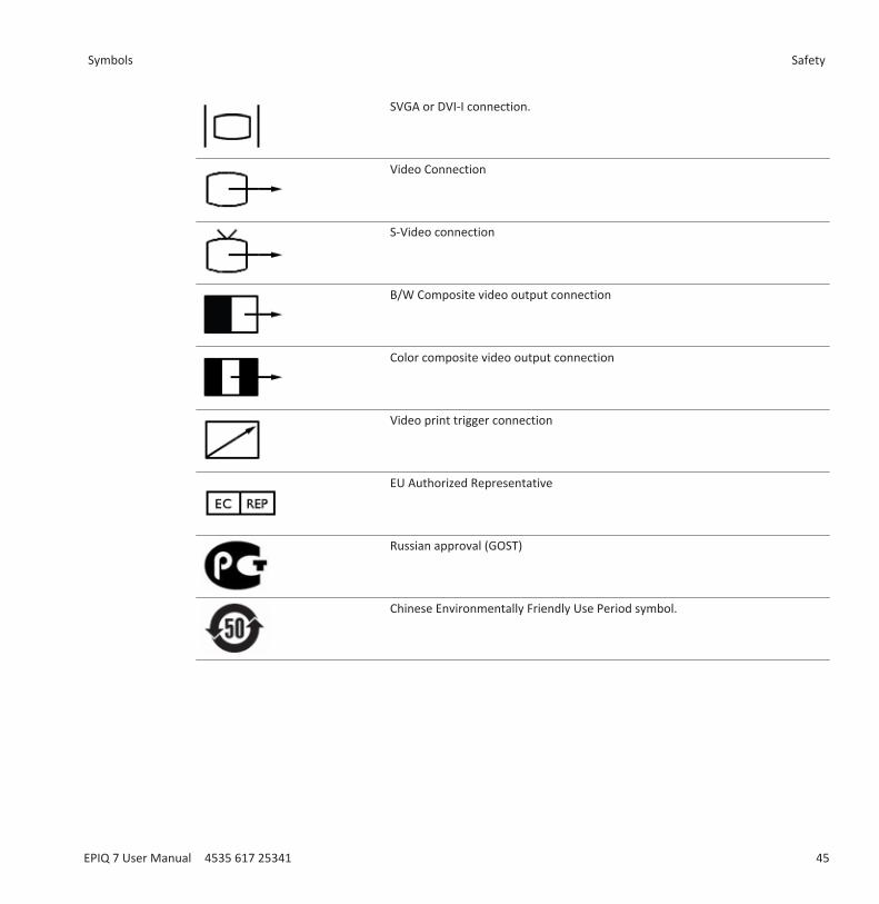
SVGA or DVI-I connection.
Video Connection
S-Video connection
B/W Composite video output connection
Color composite video output connection
Video print trigger connection
EU Authorized Representative
Russian approval (GOST)
Chinese Environmentally Friendly Use Period symbol.
Symbols Safety
EPIQ 7 User Manual 4535 617 25341 45
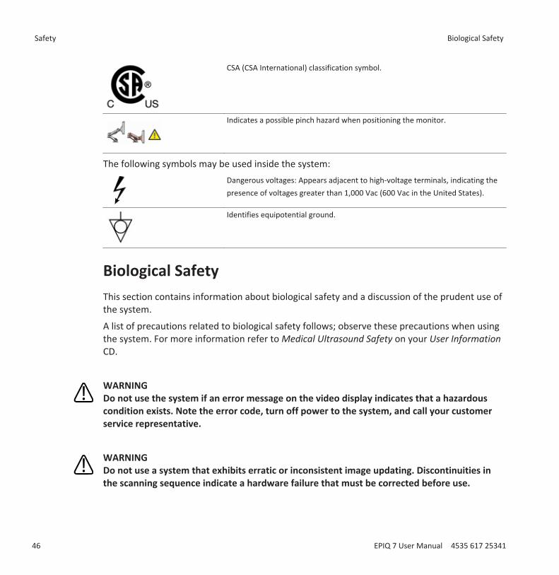
CSA (CSA International) classification symbol.
Indicates a possible pinch hazard when positioning the monitor.
The following symbols may be used inside the system:Dangerous voltages: Appears adjacent to high-voltage terminals, indicating thepresence of voltages greater than 1,000 Vac (600 Vac in the United States).
Identifies equipotential ground.
Biological SafetyThis section contains information about biological safety and a discussion of the prudent use ofthe system.
A list of precautions related to biological safety follows; observe these precautions when usingthe system. For more information refer to Medical Ultrasound Safety on your User InformationCD.
WARNINGDo not use the system if an error message on the video display indicates that a hazardouscondition exists. Note the error code, turn off power to the system, and call your customerservice representative.
WARNINGDo not use a system that exhibits erratic or inconsistent image updating. Discontinuities inthe scanning sequence indicate a hardware failure that must be corrected before use.
Safety Biological Safety
46 EPIQ 7 User Manual 4535 617 25341
WARNINGPerform ultrasound procedures prudently. Use the ALARA (as low as reasonably achievable)principle.
WARNINGUse only acoustic standoffs that have been approved by Philips Ultrasound. For informationon ordering approved accessories, see “Supplies and Accessories” on page 21.
WARNINGVerify the alignment of the biopsy guide before use. See the “Biopsy Guides” section.
WARNINGVerify the condition of the biopsy needle before use. Do not use a bent biopsy needle.
WARNINGTransducer covers may contain natural rubber latex. Those covers may cause allergicreactions in some individuals. See “FDA Medical Alert on Latex” on page 49.
WARNINGThe M2203A bite guard strap contains natural rubber latex, which may cause allergicreactions. See “FDA Medical Alert on Latex” on page 49.
WARNINGIn contrast studies using a high-MI acoustic field, capillary rupture, due to microbubbleexpansion within a capillary in an acoustic field, can cause extravasation. References: (1)Skyba, D.M., Price, R.J., Linka, A.Z., Skalak, T.C., Kaul, S. "Direct in vivo visualization ofintravascular destruction of microbubbles by ultrasound and its local effects on tissue."Circulation, 1998; 98:290-293. (2) van Der Wouw, P.A., Brauns, A.C., Bailey, S.E., Powers, J.E.,Wilde, A.A. "Premature ventricular contractions during triggered imaging with ultrasoundcontrast." Journal of the American Society of Echocardiography, 2000;13(4):288-94.
Biological Safety Safety
EPIQ 7 User Manual 4535 617 25341 47
WARNINGPreventricular contractions can be caused by the oscillations of microbubbles when a high-MIacoustic field is triggered in the heart at the end of systole. In a very sick patient with certainrisk factors, theoretically, this could lead to ventricular fibrillation. Reference: van Der Wouw,P.A., Brauns, A.C., Bailey, S.E., Powers, J.E., Wilde, A.A. "Premature ventricular contractionsduring triggered imaging with ultrasound contrast." Journal of the American Society ofEchocardiography, 2000;13(4):288-94.
WARNINGIf a sterile transducer cover becomes compromised during an intraoperative applicationinvolving a patient with transmissible spongiform encephalopathy, such as Creutzfeldt-Jakobdisease, follow the guidelines of the U.S. Centers for Disease Control and this document fromthe World Health Organization: WHO/CDS/ APH/2000/3, WHO Infection Control Guidelinesfor Transmissible Spongiform Encephalopathies. The transducers for your system cannot bedecontaminated using a heat process.
WARNINGIf the system becomes contaminated internally with bodily fluids carrying pathogens, youmust immediately notify your Philips service representative. Components inside the systemcannot be disinfected. In that case, the system must be disposed of as biohazardous materialin accordance with local or federal laws.
WARNINGThe backlight lamps in the system displays may contain mercury and must be recycled ordisposed of according to local, state, or federal laws.
WARNINGSelect the correct application when starting an exam, and remain in that applicationthroughout the exam. Some applications are for parts of the body that require lower limitsfor acoustic output.
Safety Biological Safety
48 EPIQ 7 User Manual 4535 617 25341
FDA Medical Alert on LatexMarch 29, 1991, Allergic Reactions to Latex-Containing Medical Devices
Because of reports of severe allergic reactions to medical devices containing latex (naturalrubber), the FDA is advising health care professionals to identify their latex sensitive patientsand be prepared to treat allergic reactions promptly. Patient reactions to latex have rangedfrom contact urticaria to systemic anaphylaxis. Latex is a component of many medical devices,including surgical and examination gloves, catheters, intubation tubes, anesthesia masks, anddental dams.
Reports to the FDA of allergic reactions to latex-containing medical devices have increasedlately. One brand of latex cuffed enema tips was recently recalled after several patients died asa result of anaphylactoid reactions during barium enema procedures. More reports of latexsensitivity have also been found in the medical literature. Repeated exposure to latex both inmedical devices and in other consumer products may be part of the reason that the prevalenceof latex sensitivity appears to be increasing. For example, it has been reported that 6% to 7% ofsurgical personnel and 18% to 40% of spina bifida patients are latex sensitive.
Proteins in the latex itself appear to be the primary source of the allergic reactions. Although itis not now known how much protein is likely to cause severe reactions, the FDA is working withmanufacturers of latex-containing medical devices to make protein levels in their products aslow as possible.
FDA’s recommendations to health professionals in regard to this problem are as follows:• When taking general histories of patients, include questions about latex sensitivity. For
surgical and radiology patients, spina bifida patients and health care workers, thisrecommendation is especially important. Questions about itching, rash or wheezing afterwearing latex gloves or inflating a toy balloon may be useful. Patients with positive historiesshould have their charts flagged.
• If latex sensitivity is suspected, consider using devices made with alternative materials, suchas plastic. For example, a health professional could wear a non-latex glove over the latexglove if the patient is sensitive. If both the health professional and the patient are sensitive,a latex middle glove could be used. (Latex gloves labeled “Hypoallergenic” may not alwaysprevent adverse reactions.)
• Whenever latex-containing medical devices are used, especially when the latex comes incontact with mucous membranes, be alert to the possibility of an allergic reaction.
Biological Safety Safety
EPIQ 7 User Manual 4535 617 25341 49

• If an allergic reaction does occur and latex is suspected, advise the patient of a possiblelatex sensitivity and consider an immunologic evaluation.
• Advise the patient to tell health professionals and emergency personnel about any knownlatex sensitivity before undergoing medical procedures. Consider advising patients withsevere latex sensitivity to wear a medical identification bracelet.
The FDA is asking health professionals to report incidents of adverse reactions to latex or othermaterials used in medical devices. (See the October 1990 FDA Drug Bulletin.) To report anincident, contact the FDA Problem Reporting Program, MedWatch, at 1-800-332-1088, or onthe Internet:
www.fda.gov/Safety/MedWatch/
For a single copy of a reference list on latex sensitivity, write to: LATEX, FDA, HFZ-220, Rockville,MD 20857.
NOTEThe ultrasound system and transducers described in this document do not contain naturalrubber latex that contacts humans. Natural rubber latex is not used on any Philips ultrasoundtransducer. It also is not used on Philips ECG cables for the products described in thisdocument.
ALARA Education ProgramThe guiding principle for the use of diagnostic ultrasound is defined by the "as low asreasonably achievable" (ALARA) principle. The decision as to what is reasonable has been left tothe judgment and insight of qualified personnel. No set of rules can be formulated that wouldbe sufficiently complete to dictate the correct response to every circumstance. By keepingultrasound exposure as low as possible, while obtaining diagnostic images, users can minimizeultrasonic bioeffects.
Since the threshold for diagnostic ultrasound bioeffects is undetermined, it is the sonographer’sresponsibility to control total energy transmitted into the patient. The sonographer mustreconcile exposure time with diagnostic image quality. To ensure diagnostic image quality andlimit exposure time, an ultrasound system provides controls that can be manipulated during theexam to optimize the results of the exam.
Safety Biological Safety
50 EPIQ 7 User Manual 4535 617 25341

The ability of the user to abide by the ALARA principle is important. Advances in diagnosticultrasound, not only in the technology but in the applications of that technology, have resultedin the need for more and better information to guide the user. The output display indices aredesigned to provide that important information.
There are a number of variables which affect the way in which the output display indices can beused to implement the ALARA principle. These variables include index values, body size,location of the bone relative to the focal point, attenuation in the body, and ultrasoundexposure time. Exposure time is an especially useful variable, because it is controlled by theuser. The ability to limit the index values over time supports the ALARA principle.
Applying ALARA
The system imaging mode used depends upon the information needed. 2D and M‑modeimaging provide anatomical information, while Doppler, Color Power Angio (CPA), and Colorimaging provide information about blood flow. A scanned mode, like 2D or Color, disperses orscatters the ultrasonic energy over an area, while an unscanned mode, like M‑mode or Doppler,concentrates ultrasonic energy. Understanding the nature of the imaging mode being usedallows the sonographer to apply the ALARA principle with informed judgment. Additionally, thetransducer frequency, system setup values, scanning techniques, and operator experienceallow the sonographer to meet the definition of the ALARA principle.
The decision as to the amount of acoustic output is, in the final analysis, up to the systemoperator. This decision must be based on the following factors: type of patient, type of exam,patient history, ease or difficulty of obtaining diagnostically useful information, and thepotential localized heating of the patient due to transducer surface temperatures. Prudent useof the system occurs when patient exposure is limited to the lowest index reading for theshortest amount of time necessary to achieve acceptable diagnostic results.
Although a high index reading does not mean that a bioeffect is actually occurring, a high indexreading should be taken seriously. Every effort should be made to reduce the possible effects ofa high index reading. Limiting exposure time is an effective way to accomplish this goal.
There are several system controls that the operator can use to adjust the image quality andlimit the acoustic intensity. These controls are related to the techniques that an operator mightuse to implement ALARA. These controls can be divided into three categories: direct, indirect,and receiver controls.
Biological Safety Safety
EPIQ 7 User Manual 4535 617 25341 51
Acoustic Output Limits
This ultrasound system maintains acoustic output below the appropriate limits for eachapplication, as listed here. The significant difference in magnitude emphasizes the need toselect the correct application and remain in that application, so the correct application limitsare in use for the appropriate application.
Limits for Non-Ophthalmic Applications• Ispta.3 ≤ 720 mW/cm2
• MI ≤ 1.9• TI ≤ 6.0
Limits for Ophthalmic Applications• Ispta.3 ≤ 50 mW/cm2
• MI ≤ 0.23• TI ≤ 1.0
Direct Controls
Application selection and the output-power control directly affect acoustic intensity. There aredifferent ranges of allowable intensity or output based on your selection. Selecting the correctrange of acoustic intensity for the application is one of the first things that occurs in any exam.For example, peripheral vascular intensity levels are not recommended for fetal exams. Somesystems automatically select the proper range for a particular application, while others requiremanual selection. Ultimately, the user has the responsibility for proper clinical use. Theultrasound system provides both automatic (default) settings and manual (user-selectable)settings.
Output power has direct impact on acoustic intensity. Once the application has beenestablished, the power control can be used to increase or decrease the intensity output. Thepower control allows you to select intensity levels less than the established maximum. Prudentuse dictates that you select the lowest output intensity that is consistent with good imagequality.
Indirect Controls
The indirect controls are those that have an indirect effect on acoustic intensity. These controlsaffect imaging mode, pulse repetition frequency, focus depth, pulse length, and transducerselection.
Safety Biological Safety
52 EPIQ 7 User Manual 4535 617 25341
The choice of imaging mode determines the nature of the ultrasound beam. 2D is a scanningmode; Doppler is a stationary or unscanned mode. A stationary ultrasound beam concentratesenergy in a single location. A moving or scanned ultrasound beam disperses the energy over anarea and the beam is concentrated on the same area for a fraction of the time as that of anunscanned mode.
Pulse repetition frequency or rate refers to the number of ultrasound bursts of energy over aspecific period of time. The higher the pulse repetition frequency, the more pulses of energy ina period of time. Several controls affect pulse repetition frequency: focal depth, display depth,sample volume depth, flow optimization, scale, number of focal zones, and sector-widthcontrols.
Focus of the ultrasound beam affects the image resolution. To maintain or increase resolutionat a different focus requires a variation in output over the focal zone. This variation of output isa function of system optimization. Different exams require different focal depths. Setting thefocus at the proper depth improves the resolution of the structure of interest.
Pulse length is the time during which the ultrasonic burst is turned on. The longer the pulse, thegreater the time-average intensity value. The greater the time-average intensity, the greaterthe likelihood of temperature increase and cavitation. Pulse length, burst length, or pulseduration is the output pulse duration in PW Doppler. Increasing the Doppler sample-volumesize increases the pulse length.
Transducer selection indirectly affects intensity. Tissue attenuation changes with frequency.The higher the transducer operating frequency, the greater the attenuation of the ultrasonicenergy. A higher transducer operating frequency requires more output intensity to scan at adeeper depth. To scan deeper at the same output intensity, a lower transducer frequency isrequired. Using more gain and output beyond a point, without corresponding increases inimage quality, can mean that a lower frequency transducer is needed.
Receiver Controls
Receiver controls are used by the operator to improve image quality. These controls have noeffect on output. Receiver controls only affect how the ultrasound echo is received. Thesecontrols include gain, TGC, dynamic range, and image processing. The important thing toremember, relative to output, is that receiver controls should be optimized before output isincreased. For example, before increasing output, optimize gain to improve image quality.
Biological Safety Safety
EPIQ 7 User Manual 4535 617 25341 53
An Example of Applying the ALARA Principle
An ultrasound scan of a patient’s liver begins with selecting the appropriate transducerfrequency. After selecting the transducer and the application, which are based on patientanatomy, adjustments to output power should be made to ensure that the lowest possiblesetting is used to acquire an image. After the image is acquired, adjusting the focus of thetransducer, and then increasing the receiver gain to produce a uniform representation of thetissue follows. If an adequate image can be obtained with the increase in gain, then a decreasein output should be made. Only after making these adjustments should you increase output tothe next level.
Having acquired the 2D display of the liver, Color can be used to localize blood flow. As with the2D image display, gain and image processing controls must be optimized before increasingoutput.
Having localized the blood flow, use the Doppler controls to position the sample volume overthe vessel. Before increasing output, adjust velocity range or scale and Doppler gain to obtainan optimal Doppler trace. Only if maximum Doppler gain does not create an acceptable imagedo you increase output.
In summary: Select the correct transducer frequency and application for the job; start with alow output level; and optimize the image by using focus, receiver gain, and other imagingcontrols. If the image is not diagnostically useful at this point, then increase output.
Additional Considerations
Ensure that scanning time is kept to a minimum, and ensure that only medically requiredscanning is performed. Never compromise quality by rushing through an exam. A poor exammay require a follow‑up, which ultimately increases exposure time. Diagnostic ultrasound is animportant tool in medicine, and like any tool, it should be used efficiently and effectively.
Output DisplayThe system output display comprises two basic indices: a mechanical index and a thermal index.
The mechanical index is continuously displayed over the range of 0.0 to 1.9, in increments of0.1 for all applications except contrast, where the minimum increment is 0.01.
Safety Biological Safety
54 EPIQ 7 User Manual 4535 617 25341
The thermal index further consists of the following indices: soft tissue (TIS), bone (TIB), andcranial bone (TIC). Only one of these is displayed at any time. Each transducer application has adefault selection that is appropriate for that combination. The TIB, TIS, or TIC is continuouslydisplayed over the range of 0.0 to maximum output, based on the transducer and application,in increments of 0.1. For the location of the output display, see “Imaging Display” on page 135.
The application-specific nature of the default setting is also an important factor of indexbehavior. A default setting is a system control state that is preset by the manufacturer or theoperator. The system has default index settings for the transducer application. The defaultsettings are invoked automatically by the ultrasound system when power is turned on, whennew patient data is entered into the system database, or when an application change occurs.
The decision as to which of the three thermal indices to display should be based on thefollowing criteria:• Appropriate index for the application: TIS is used for imaging soft tissue, TIB for a focus at or
near bone, and TIC for imaging through bone near the surface, as in a cranial exam.• Mitigating factors that might create artificially high or low thermal index readings: location
of fluid or bone, or blood flow. For example, is there a highly attenuating tissue path so thatthe actual potential for local zone heating is less than the thermal index displays?
• Scanned modes versus unscanned modes of operation affect the thermal index. Forscanned modes, heating tends to be near the surface; for unscanned modes, the potentialfor heating tends to be deeper in the focal zone.
• Always limit ultrasound exposure time. Do not rush the exam. Ensure that the indices arekept to a minimum and that exposure time is limited without compromising diagnosticsensitivity.
Mechanical Index (MI) Display
Mechanical bioeffects are threshold phenomena that occur when a certain level of output isexceeded. The threshold level varies, however, with the type of tissue. The potential formechanical bioeffects varies with peak rarefactional pressure and ultrasound frequency. The MIaccounts for these two factors. The higher the MI value, the greater the likelihood ofmechanical bioeffects occurring. There is no specific MI value that means that a mechanicaleffect is actually occurring. The MI should be used as a guide for implementing the ALARAprinciple.
Biological Safety Safety
EPIQ 7 User Manual 4535 617 25341 55

Thermal Index (TI) Displays
The TI informs the user about the conditions that exist that might lead to an increase intemperature at the surface of the body, within the body tissue, or at the point of focus of theultrasound beam on bone. That is, the TI informs the user of the potential for temperature risein body tissue. It is an estimate of temperature increase in body tissue with specific properties.The actual amount of any temperature rise is influenced by factors such as tissue type,vascularity, mode of operation, and others. The TI should be used as a guide for implementingthe ALARA principle.
The bone thermal index (TIB) informs the user about potential heating at or near the focus afterthe ultrasound beam has passed through soft tissue or fluid; for example, at or near second- orthird-trimester fetal bone.
The cranial bone thermal index (TIC) informs the user about the potential heating of bone at ornear the surface; for example, cranial bone.
The soft tissue thermal index (TIS) informs the user about the potential for heating within softhomogeneous tissue.
You can choose to display TIS, TIC, or TIB. (For details on changing the TI display, see the systemHelp.) On systems with transcranial applications, TIC is displayed when you select a transcranialpreset.
Mechanical and Thermal Indices Display Precision and Accuracy
The MI and TI precision is 0.1 unit on the system.
The MI and TI display accuracy estimates for the system are given in Acoustic Output Tables, onyour user information CD. Those accuracy estimates are based on the variability range oftransducers and systems, inherent acoustic output modeling errors, and measurementvariability, as discussed in this section.
The displayed values should be interpreted as relative information to help the system operatorachieve the ALARA principle through prudent use of the system. The values should not beinterpreted as actual physical values in interrogated tissue or organs. The initial data that isused to support the output display is derived from laboratory measurements based on theAmerican Institute of Ultrasound in Medicine (AIUM) measurement standard. Themeasurements are then put into algorithms for calculating the displayed output values.
Safety Biological Safety
56 EPIQ 7 User Manual 4535 617 25341
Many of the assumptions used in the process of measurement and calculation are conservativein nature. Overestimation of actual in situ intensity exposure, for the vast majority of tissuepaths, is built into the measurement and calculation process. For example:• The measured water tank values are derated using a conservative, industry standard,
attenuation coefficient of 0.3 dB/cm-MHz.• Conservative values for tissue characteristics were selected for use in the TI models.
Conservative values for tissue or bone absorption rates, blood perfusion rates, blood heatcapacity, and tissue thermal conductivity were selected.
• Steady State temperature rise is assumed in the industry standard TI models, and theassumption is made that the ultrasound transducer is held steady in one position longenough for steady state to be reached.
A number of factors are considered when estimating the accuracy of the displayed values:hardware variations, estimation algorithm accuracy, and measurement variability. Variabilityamong transducers and systems is a significant factor. Transducer variability results frompiezoelectric crystal efficiencies, process-related impedance differences, and sensitive lens-focusing parameter variations. Differences in system pulser voltage control and efficiencies isalso a contributor to variability. There are inherent uncertainties in the algorithms used toestimate acoustic output values over the range of possible system operating conditions andpulser voltages. Inaccuracies in laboratory measurements are related to, among others,differences in hydrophone calibration and performance, positioning, alignment, and digitizationtolerances, and variability among test operators.
The conservative assumptions of the output estimation algorithms of linear propagation, at alldepths, through a 0.3 dB/cm-MHz attenuative medium is not considered in the accuracyestimate for the display. Neither linear propagation, nor uniform attenuation at the 0.3 dB/cm-MHz rate, occur in water tank measurements or in most tissue paths in the body. In the body,different tissues and organs have dissimilar attenuation characteristics. In water, there isalmost no attenuation. In the body, and in particular, in water tank measurements, nonlinearpropagation and saturation losses occur as pulser voltages increase.
Therefore, the display accuracy estimates are based on the variability range of transducers andsystems, inherent acoustic output modeling errors, and measurement variability. Displayaccuracy estimates are not based on errors in, or caused by measuring according to, the AIUMmeasurement standards, or the effects of nonlinear loss on the measured values.
Biological Safety Safety
EPIQ 7 User Manual 4535 617 25341 57

Control Effects
Controls Affecting the Indices
As various system controls are adjusted, the TI and MI values may change. This will be mostapparent as the output power control is adjusted; but other system controls affect theon‑screen output values.
Power
The output power control affects the system acoustic output. Two real‑time output values areon the display: TI and MI. They change as the system responds to power-control adjustments.
In combined modes, such as simultaneous Color, 2D, and PW Doppler, the individual modeseach add to the total TI. One mode will be the dominant contributor to this total. The displayedMI will be from the mode with the largest MI value.
2D Controls• Sector Width: Narrowing the sector angle may increase frame rate. This action will increase
the TI. Pulser voltage may be automatically adjusted down with software controls to keepthe TI below the system maximums. A decrease in pulser voltage will decrease MI.
• Zoom: Increasing the zoom magnification by pressing Zoom may increase frame rate. Thisaction will increase the TI. The number of focal zones may also increase automatically toimprove resolution. This action may change the MI, because the peak MI can occur at adifferent depth.
• Number of Focal Zones: More focal zones may change both the TI and MI by changingframe rate or focal depth automatically. Lower frame rates decrease the TI. MI displayedwill correspond to the zone with the largest MI value.
• Focus: Changing the focal depth will change MI. Generally, higher MI values will occur whenthe focal depth is near the natural focus of the transducer.
Color and Power Controls• Flow Opt: Increasing the color sensitivity with the Flow Opt control may increase the TI.
More time is spent scanning the color image. Color pulses are the dominant pulse type inthis mode.
Safety Biological Safety
58 EPIQ 7 User Manual 4535 617 25341

• Color Sector Width: Narrower color sector width will increase color frame rate and the TIwill increase. The system may automatically decrease pulser voltage to stay below thesystem maximum. A decrease in pulser voltage will decrease the MI. If PW Doppler is alsoenabled, then PW Doppler will remain the dominant mode and the TI change will be small.
• Color Sector Depth: Deeper color sector depth may automatically decrease color frame rateor select a new color focal zone or color pulse length. The TI will change due to thecombination of these effects. Generally, the TI will decrease with increased color sectordepth. MI will correspond to the MI of the dominant pulse type which is a color pulse.However, if PW Doppler is also enabled then PW Doppler will remain the dominant modeand the TI change will be small.
• Scale: Using the scale control to increase the color velocity range may increase the TI. Thesystem may automatically adjust pulser voltage to stay below the system maximums. Adecrease in pulser voltage will also decrease MI.
• Sector Width: A narrower 2D sector width in Color imaging will increase color frame rate.The TI will increase. MI will change little, if at all. If PW Doppler is also enabled, then PWDoppler will remain the dominant mode and the TI change will be small.
M‑Mode and Doppler Controls• Simultaneous and Update Methods: Use of combination modes affects both the TI and MI
through the combination of pulse types. During simultaneous mode, the TI is additive.During Duplex, the TI will display the dominant pulse type. The displayed MI will be fromthe mode with the largest MI value.
• Sample Volume Depth: When Doppler sample volume depth is decreased, the Dopplerpulse repetition frequency (PRF) may automatically increase. An increase in PRF willincrease the TI. The system may also automatically decrease the pulser voltage to remainbelow the system maximum. A decrease in pulser voltage will decrease MI.
Other Control Effects• Imaging Mode Controls: When a new imaging mode is selected, both the TI and MI may
change to default settings. Each mode has a corresponding pulse repetition frequency andmaximum intensity point. In combined or simultaneous modes, the TI is the sum of thecontribution from the modes enabled, and the displayed MI is the largest of the MI valuesassociated with each mode and focal zone enabled. The system will return to the previouslyselected state if a mode is turned off and then reselected.
Biological Safety Safety
EPIQ 7 User Manual 4535 617 25341 59
• Transducer: Each transducer type has unique specifications for contact area, beam shape,and center frequency. Defaults are initialized when you select a transducer. Factory defaultsvary with transducer, application, and selected mode. Defaults have been chosen below theFDA limits for intended use.
• 2D Depth: An increase in 2D depth will automatically decrease the 2D frame rate. This willdecrease the TI. The system may also automatically choose a deeper 2D focal depth. Achange of focal depth may change the MI. The MI displayed is that of the zone with thelargest MI value.
• Application: Acoustic output defaults are set when you select an application. Factorydefaults vary with transducer, application, and mode. Defaults have been chosen below theFDA limits for intended use.
Related Guidance DocumentsFor more information about ultrasonic bioeffects and related topics, see the following:• "Bioeffects and Safety of Diagnostic Ultrasound." AIUM Report, January 28, 1993.• "American Institute of Ultrasound in Medicine Bioeffects Consensus Report." Journal of
Ultrasound in Medicine, Vol. 27, Issue 4, April 2008.• Acoustic Output Measurement Standard for Diagnostic Ultrasound Equipment. (AIUM,
NEMA, 2004)• Second Edition of the AIUM Medical Ultrasound Safety brochure, 2009. (A copy of this
document is provided with each system.)• Information for Manufacturers Seeking Marketing Clearance of Diagnostic Ultrasound
Systems and Transducers. FDA, September 2008.• Standard for Real‑Time Display of Thermal and Mechanical Acoustic Output Indices on
Diagnostic Ultrasound Equipment. (AIUM, NEMA, 2004)• WFUMB. "Symposium on Safety of Ultrasound in Medicine: Conclusions and
Recommendations on Thermal and Non‑Thermal Mechanisms for Biological Effects ofUltrasound." Ultrasound in Medicine and Biology, 1998: Vol. 24, Supplement 1.
Acoustic Output and MeasurementSince the initial use of diagnostic ultrasound, the possible human bioeffects from ultrasoundexposure have been studied by various scientific and medical institutions. In October 1987, theAmerican Institute of Ultrasound in Medicine (AIUM) ratified a report prepared by its BioeffectsCommittee ("Bioeffects Considerations for the Safety of Diagnostic Ultrasound." Journal of
Safety Biological Safety
60 EPIQ 7 User Manual 4535 617 25341
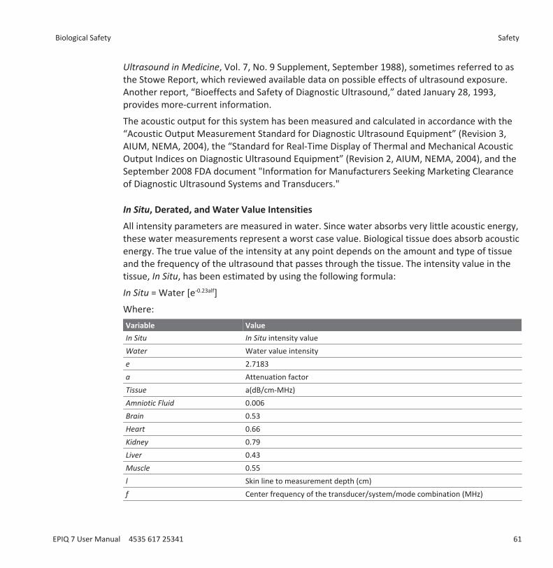
Ultrasound in Medicine, Vol. 7, No. 9 Supplement, September 1988), sometimes referred to asthe Stowe Report, which reviewed available data on possible effects of ultrasound exposure.Another report, “Bioeffects and Safety of Diagnostic Ultrasound,” dated January 28, 1993,provides more-current information.
The acoustic output for this system has been measured and calculated in accordance with the“Acoustic Output Measurement Standard for Diagnostic Ultrasound Equipment” (Revision 3,AIUM, NEMA, 2004), the “Standard for Real-Time Display of Thermal and Mechanical AcousticOutput Indices on Diagnostic Ultrasound Equipment” (Revision 2, AIUM, NEMA, 2004), and theSeptember 2008 FDA document "Information for Manufacturers Seeking Marketing Clearanceof Diagnostic Ultrasound Systems and Transducers."
In Situ, Derated, and Water Value Intensities
All intensity parameters are measured in water. Since water absorbs very little acoustic energy,these water measurements represent a worst case value. Biological tissue does absorb acousticenergy. The true value of the intensity at any point depends on the amount and type of tissueand the frequency of the ultrasound that passes through the tissue. The intensity value in thetissue, In Situ, has been estimated by using the following formula:
In Situ = Water [e-0.23alf]
Where:Variable ValueIn Situ In Situ intensity valueWater Water value intensitye 2.7183a Attenuation factorTissue a(dB/cm-MHz)Amniotic Fluid 0.006Brain 0.53Heart 0.66Kidney 0.79Liver 0.43Muscle 0.55l Skin line to measurement depth (cm)f Center frequency of the transducer/system/mode combination (MHz)
Biological Safety Safety
EPIQ 7 User Manual 4535 617 25341 61

Since the ultrasonic path during an examination is likely to pass through varying lengths andtypes of tissue, it is difficult to estimate the true in situ intensity. An attenuation factor of 0.3 isused for general reporting purposes; therefore, the In Situ value which is commonly reporteduses the formula:
In Situ derated = Water [e-0.069lf]
Since this value is not the true in situ intensity, the term “derated” is used.
Mathematical derating of water based measurements using the 0.3 dB/cm-MHz coefficient,may yield lower acoustic exposure values than would be measured in a homogenous0.3 dB/cm-MHz tissue. This is true because nonlinearly propagating acoustic energy waveformsexperience more distortion, saturation, and absorption in water than in tissue, whereattenuation present all along the tissue path will dampen the buildup of nonlinear effects.
The maximum derated and the maximum water values do not always occur at the sameoperating conditions; therefore, the reported maximum water and derated values may not berelated by the in situ (derated) formula. For example: A multi-zone array transducer that hasmaximum water value intensities in its deepest zone may have its largest derated intensity inone of its shallowest focal zones.
Conclusions Regarding Tissue Models and Equipment Survey
Tissue models are necessary to estimate attenuation and acoustic exposure levels in situ frommeasurements of acoustic output made in water. Presently, available models may be limited intheir accuracy because of varying tissue paths during diagnostic ultrasound exposures anduncertainties in acoustical properties of soft tissues. No single tissue model is adequate forpredicting exposures in all situations from measurements made in water, and continuedimprovement and verification of these models is necessary for making exposure assessmentsfor specific applications.
A homogeneous tissue model with an attenuation coefficient of 0.3 dB/cm-MHz throughout thebeam path is commonly used when estimating exposure levels. The model is conservative inthat it overestimates the in situ acoustic exposure when the path between the transducer andthe site of interest is composed entirely of soft tissue, because the attenuation coefficient ofsoft tissue is generally higher than 0.3 dB/cm-MHz. When the path contains significant amountsof fluid, as in many first- and second-trimester pregnancies scanned transabdominally, thismodel may underestimate the in situ acoustical exposure. The amount of underestimation
Safety Biological Safety
62 EPIQ 7 User Manual 4535 617 25341
depends on each specific situation. For example, when the beam path is longer than 3 cm andthe propagation medium is predominantly fluid (conditions that may exist duringtransabdominal OB scans), a more accurate value for the derating term is 0.1 dB/cm-MHz.
Fixed-path tissue models, in which soft tissue thickness is held constant, sometimes are used toestimate in situ acoustical exposures when the beam path is longer than 3 cm and consistslargely of fluid. When this model is used to estimate maximum exposure to the fetus duringtransabdominal scans, a value of 1 dB/MHz may be used during all trimesters.
The maximum acoustic output levels of diagnostic ultrasound devices extend over a broadrange of values:• A survey of 1990-equipment models yielded mechanical index (MI) values between 0.1 and
1 at their highest output settings. Maximum MI values of approximately 2 are known tooccur for currently available equipment. Maximum MI values are similar for real-time 2D,M-mode, PW Doppler, and Color flow imaging.
• Computed estimates of upper limits to temperature elevations during transabdominal scanswere obtained in a survey of 1988 and 1990 PW Doppler equipment. The vast majority ofmodels yielded upper limits less than 1°C and 4°C for exposures of first-trimester fetaltissue and second-trimester fetal bone, respectively. The largest values obtained wereapproximately 1.5°C for first-trimester fetal tissue and 7°C for second-trimester fetal bone.Estimated maximum temperature elevations given here are for a “fixed-path” tissue modeland are for devices having Ispta (derated) values greater than 500 mW/cm2. Thetemperature elevations for fetal bone and tissue were computed based on calculationprocedures given in Sections 4.3.2.1 through 4.3.2.6 in "Bioeffects and Safety of DiagnosticUltrasound" (AIUM Report, January 28, 1993).
Acoustic Output TablesAcoustic output tables are in Acoustic Output Tables, on your User Information CD.
Acoustic Measurement Precision and UncertaintyAll table entries have been obtained at the same operating conditions that give rise to themaximum index value in the first column of the tables. Measurement precision and uncertaintyfor power, pressure, intensity, and center frequency are listed in the following tables.
Biological Safety Safety
EPIQ 7 User Manual 4535 617 25341 63
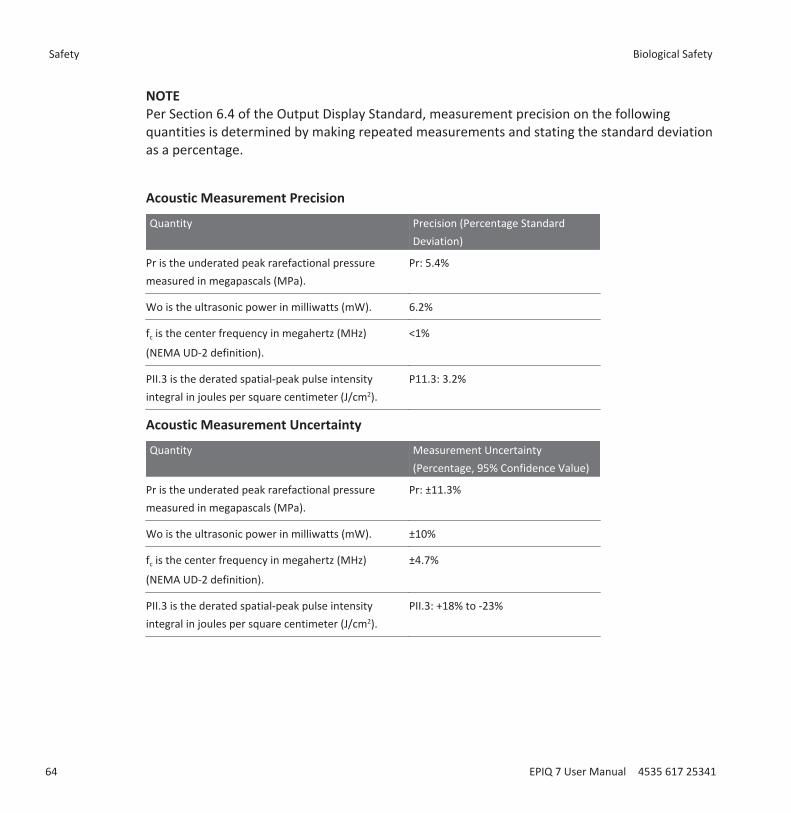
NOTEPer Section 6.4 of the Output Display Standard, measurement precision on the followingquantities is determined by making repeated measurements and stating the standard deviationas a percentage.
Acoustic Measurement Precision
Quantity Precision (Percentage StandardDeviation)
Pr is the underated peak rarefactional pressuremeasured in megapascals (MPa).
Pr: 5.4%
Wo is the ultrasonic power in milliwatts (mW). 6.2%
fc is the center frequency in megahertz (MHz)
(NEMA UD-2 definition).
<1%
PII.3 is the derated spatial-peak pulse intensityintegral in joules per square centimeter (J/cm2).
P11.3: 3.2%
Acoustic Measurement Uncertainty
Quantity Measurement Uncertainty(Percentage, 95% Confidence Value)
Pr is the underated peak rarefactional pressuremeasured in megapascals (MPa).
Pr: ±11.3%
Wo is the ultrasonic power in milliwatts (mW). ±10%
fc is the center frequency in megahertz (MHz)
(NEMA UD-2 definition).
±4.7%
PII.3 is the derated spatial-peak pulse intensityintegral in joules per square centimeter (J/cm2).
PII.3: +18% to -23%
Safety Biological Safety
64 EPIQ 7 User Manual 4535 617 25341
Operator SafetyThe following issues and situations can affect operator safety when you are using an ultrasoundsystem.
Repetitive Strain Injury Repetitive ultrasound scanning has been associated with carpal tunnel syndrome (CTS) andrelated musculoskeletal problems. Some investigators have looked at a large population ofsonographers with different types of equipment. An article, with feedback from a smallergeographical area, makes the following recommendations:• Maintain your joints in optimum positions with a balanced posture while scanning.• Allow frequent breaks to give soft tissue a chance to recuperate from awkward positions
and repetitive movement.• Avoid gripping the transducer with excessive force.
Repetitive Strain References
Pike, I., et al. "Prevalence of Musculoskeletal Disorders and Related Work and Personal FactorsAmong Diagnostic Medical Sonographers." Journal of Diagnostic Medical Sonographers, Vol. 13,No. 5: 219-227, September 1997.
Necas, M. "Musculoskeletal Symptomatology and Repetitive Strain Injuries in DiagnosticMedical Sonographer." Journal of Diagnostic Medical Sonographers, 266-227, November/December 1996.
Foot Switch Warning
WARNINGThe foot switch is not intended for use in wet locations, such as emergency rooms andoperating theaters.
Operator Safety Safety
EPIQ 7 User Manual 4535 617 25341 65
Philips TransducersUse only transducers that are approved by Philips for use with your Philips ultrasound system.See “Clinical Applications and Transducers” on page 174 for a list of the transducers that arecompatible with your ultrasound system.
In the United States, the FDA 510(k) regulatory clearance for use of the product is applicableonly when Philips-manufactured transducers are connected to the system.
Glutaraldehyde ExposureThe United States Occupational Safety and Health Administration (OSHA) has issued aregulation covering levels of acceptable glutaraldehyde exposure in the working environment.Philips does not sell glutaraldehyde-based disinfectants with its products, but this type ofdisinfectant is recommended for the disinfection of transducers used in TEE, intraoperative,endocavity, and biopsy procedures.
To reduce the presence of glutaraldehyde fumes in the air, be sure to use a covered orventilated soaking basin. Such systems are commercially available. The most-currentinformation about disinfection products and Philips transducers can be found on the PhilipsTransducer Care website:
www.healthcare.philips.com/us_en/products/ultrasound/Transducers/transducer_care/index.wpd
Infection ControlIssues related to infection control affect the operator and the patient. Follow the infection-control procedures established in your facility for the protection of both the staff and thepatient.
Handling Contaminated Transducers
The primary area of concern is the handling of transducers that have contacted infectedpatients. Always wear gloves when you handle transducers used in TEE, endocavity,intraoperative, and biopsy procedures that have not been previously disinfected.
For information on cleaning and disinfecting transducers, see the “Transducer Care” section.
Safety Operator Safety
66 EPIQ 7 User Manual 4535 617 25341
Removing Blood and Infectious Material from the System
CAUTIONDo not wipe the transducer housing joint, strain relief, or cable with isopropyl alcohol.Isopropyl alcohol can damage these parts of the transducer. This damage is not covered bythe warranty or your service contract.
Use a gauze pad moistened with soap and water to remove blood on the system and thetransducer connectors and cables. Then dry the equipment with a soft cloth to preventcorrosion. You can use a 70% solution of isopropyl alcohol on the system and only on certainparts of some transducers. Additional cleaning agents are available for transducers. For moreinformation, see the “Transducer Care” section.
For more information about removing blood and other infectious material from the system, see“Disinfecting System Surfaces” on page 290.
ECG Cables and Lead Sets
For information on cleaning ECG cables and lead sets, see “Cleaning the System and ECGEquipment” on page 287.
Disposable Drape
If you believe contamination of the system might occur during an exam, Philips recommendsthat you take universal precautions and cover the system with a disposable drape. Consult yourfacility's rules regarding equipment use in the presence of infectious disease.
CAUTIONPosition the disposable drape so that it does not block the vents on the system, the monitors,or the peripherals.
Operator Safety Safety
EPIQ 7 User Manual 4535 617 25341 67

Electromagnetic Compatibility Electromagnetic compatibility (EMC) is defined as the ability of a product, a device, or a systemto function satisfactorily in the presence of the electromagnetic phenomena that exists in thelocation of the product, the device, or the system being used; and, in addition, to not introduceintolerable electromagnetic disturbances to anything in that same environment.
Electromagnetic immunity is the ability of a product, a device, or a system to functionsatisfactorily in the presence of electromagnetic interference (EMI).
Electromagnetic emissions is the ability of a product, a device, or a system to introduceintolerable electromagnetic disturbances into the use environment.
Your system has been manufactured in compliance with existing electromagnetic compatibilityrequirements. Use of this system in the presence of an electromagnetic field can causemomentary degradation of the tracking ability. If this occurs often, review the environment inwhich the system is being used to identify possible sources of radiated emissions. Theseemissions could be from other electrical devices used within the same room or an adjacentroom, or from portable and mobile RF communications equipment such as cellular phones andpagers, or from the existence of radio, TV, or microwave transmission equipment locatednearby. In cases where electromagnetic interference (EMI) is causing disturbances, it may benecessary to relocate your system.
The system complies with International Standard CISPR 11 for radiated and conductedelectromagnetic disturbances. Compliance with this standard allows the system to be used in allestablishments, including domestic establishments and those directly connected to the publiclow-voltage power supply network that supplies buildings used for domestic purposes.
WARNINGUsing cables, transducers, or accessories other than those specified for use with the systemmay result in increased emissions or decreased immunity of the system.
CAUTIONMedical equipment has special precautions regarding EMC and must be installed and put intoservice according to the EMC information provided in the system’s accompanying documents.
Safety Electromagnetic Compatibility
68 EPIQ 7 User Manual 4535 617 25341
This section includes information on electromagnetic emissions and immunity as it applies tothe system. Ensure that the operating environment of your system meets the conditionsspecified in the referenced information. Operating the system in an environment that does notmeet these conditions may degrade system performance.
The information and warnings contained in this and other sections should be observed wheninstalling and using the system to ensure its EMC.
NOTESee the other electrical-safety warnings and cautions in this section.
If the system is operated within the electromagnetic environment described in“Electromagnetic Immunity” on page 74, the system will remain safe and will provide thefollowing essential performance:• Imaging• Doppler audio and spectral display• Measurements• Acoustic output• ECG triggering• Recording and playback on a VCR or DVD recorder• Printing using system printers• Patient information• Date and time information
Radio-Frequency EmissionsThe following information applies to the system and any radio-frequency device included in orwith the system. For information on related labeling, see “Symbols” on page 38.
FCC and Industry Canada Radio Compliance: This device complies with Part 15 of the FCC Rulesand RSS-210 of Industry Canada. Operation is subject to the following two conditions:• This device may not cause harmful interference.• This device must accept any interference received, including interference that may cause
undesired operation. Any changes or modifications to this equipment not expresslyapproved by Philips may cause harmful radio frequency interference and void yourauthority to operate this equipment.
Electromagnetic Compatibility Safety
EPIQ 7 User Manual 4535 617 25341 69
The radio component in this device is the LG-Ericsson USB-1040.
The wireless technology radio device used in this product is in compliance with the essentialrequirements and other relevant provisions of Directive 1999/5/EC. This product is intended tobe connected to the Publicly Available Interfaces and used throughout the European EconomicArea.
ECG Signal
WARNINGOperation of your system with ECG signals below 0.25 mV may cause inaccurate results.
The amplitude of the electrocardiogram (ECG) signal is critical for reliable frame triggering.Frame triggering should be used only when a clean, noise-free ECG waveform is observed onthe ECG display. The ECG signal should be at least 0.25 mV to ensure reliable triggering whenthe system is used in the presence of the electromagnetic phenomena described in this sectionand elsewhere in your system user information.
Electrostatic Discharge PrecautionsElectrostatic discharge (ESD), commonly referred to as a static shock, is a naturally occurringphenomenon that results in the flow of an electrical charge from a higher charged object orperson to a lower charged object or person. ESD is most prevalent during conditions of lowhumidity, which can be caused by heating or air-conditioning. During low humidity conditions,electrical charges naturally build up on individuals and objects and can create static discharges.
The following cautions can help to reduce ESD effect:
CAUTIONDo not touch transducer connector pins or the system’s transducer receptacle.
CAUTIONHandle the transducer by the metal connector shell.
Safety Electromagnetic Compatibility
70 EPIQ 7 User Manual 4535 617 25341
CAUTIONMake contact with a metal surface of the system before connecting a transducer to thesystem.
CAUTIONThe following precautions can help to reduce ESD: anti-static spray on carpets; anti-staticspray on linoleum; anti-static mats; or a ground wire connection between the system and thepatient table or bed.
CAUTION
On connectors labeled with the ESD sensitivity symbol , do not touch the connector pins,and always observe the preceding ESD precautions when handling or connecting transducers.
NOTEElectrostatic discharges (ESDs) may cause the ECG heart rate display to increase by 10% to 15%for a few seconds after the discharge. However, the ECG heart rate display will return to normalwithin 4 seconds.
Electromagnetic EmissionsThe system is intended for use in the electromagnetic environment specified in the table. Thecustomer or the user of the system should ensure that it is used in such an environment.
Electromagnetic Compatibility Safety
EPIQ 7 User Manual 4535 617 25341 71
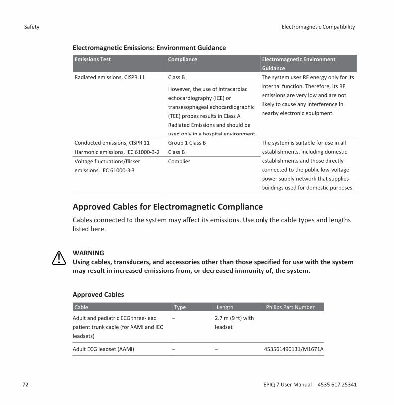
Electromagnetic Emissions: Environment GuidanceEmissions Test Compliance Electromagnetic Environment
GuidanceRadiated emissions, CISPR 11 Class B
However, the use of intracardiacechocardiography (ICE) ortransesophageal echocardiographic(TEE) probes results in Class ARadiated Emissions and should beused only in a hospital environment.
The system uses RF energy only for itsinternal function. Therefore, its RFemissions are very low and are notlikely to cause any interference innearby electronic equipment.
Conducted emissions, CISPR 11 Group 1 Class B The system is suitable for use in allestablishments, including domesticestablishments and those directlyconnected to the public low-voltagepower supply network that suppliesbuildings used for domestic purposes.
Harmonic emissions, IEC 61000-3-2 Class BVoltage fluctuations/flickeremissions, IEC 61000-3-3
Complies
Approved Cables for Electromagnetic ComplianceCables connected to the system may affect its emissions. Use only the cable types and lengthslisted here.
WARNINGUsing cables, transducers, and accessories other than those specified for use with the systemmay result in increased emissions from, or decreased immunity of, the system.
Approved Cables
Cable Type Length Philips Part Number
Adult and pediatric ECG three-leadpatient trunk cable (for AAMI and IECleadsets)
– 2.7 m (9 ft) withleadset
Adult ECG leadset (AAMI) – – 453561490131/M1671A
Safety Electromagnetic Compatibility
72 EPIQ 7 User Manual 4535 617 25341
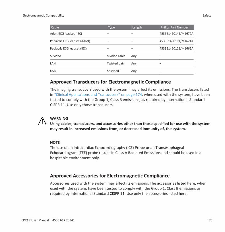
Cable Type Length Philips Part Number
Adult ECG leadset (IEC) – – 453561490141/M1672A
Pediatric ECG leadset (AAMI) – – 453561490101/M1624A
Pediatric ECG leadset (IEC) – – 453561490121/M1669A
S -video S-video cable Any –
LAN Twisted pair Any –
USB Shielded Any –
Approved Transducers for Electromagnetic ComplianceThe imaging transducers used with the system may affect its emissions. The transducers listedin “Clinical Applications and Transducers” on page 174, when used with the system, have beentested to comply with the Group 1, Class B emissions, as required by International StandardCISPR 11. Use only those transducers.
WARNINGUsing cables, transducers, and accessories other than those specified for use with the systemmay result in increased emissions from, or decreased immunity of, the system.
NOTEThe use of an Intracardiac Echocardiography (ICE) Probe or an TransesophagealEchocardiogram (TEE) probe results in Class A Radiated Emissions and should be used in ahospitable environment only.
Approved Accessories for Electromagnetic ComplianceAccessories used with the system may affect its emissions. The accessories listed here, whenused with the system, have been tested to comply with the Group 1, Class B emissions asrequired by International Standard CISPR 11. Use only the accessories listed here.
Electromagnetic Compatibility Safety
EPIQ 7 User Manual 4535 617 25341 73
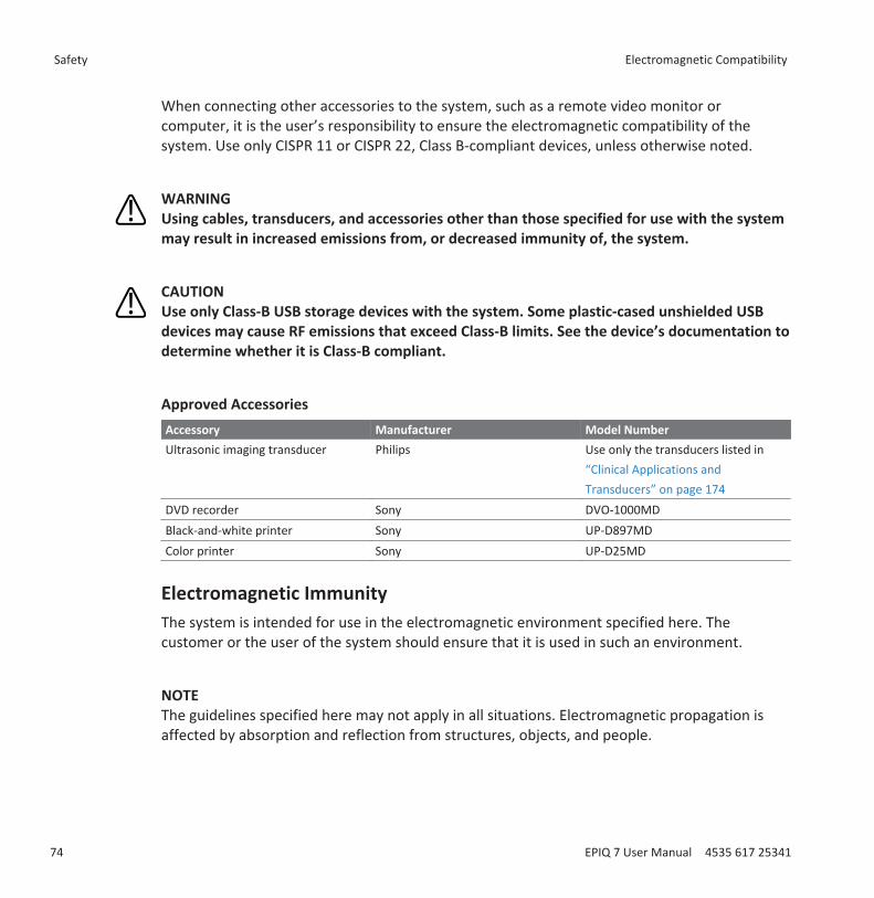
When connecting other accessories to the system, such as a remote video monitor orcomputer, it is the user’s responsibility to ensure the electromagnetic compatibility of thesystem. Use only CISPR 11 or CISPR 22, Class B-compliant devices, unless otherwise noted.
WARNINGUsing cables, transducers, and accessories other than those specified for use with the systemmay result in increased emissions from, or decreased immunity of, the system.
CAUTIONUse only Class-B USB storage devices with the system. Some plastic-cased unshielded USBdevices may cause RF emissions that exceed Class-B limits. See the device’s documentation todetermine whether it is Class-B compliant.
Approved AccessoriesAccessory Manufacturer Model NumberUltrasonic imaging transducer Philips Use only the transducers listed in
“Clinical Applications andTransducers” on page 174
DVD recorder Sony DVO-1000MDBlack-and-white printer Sony UP-D897MDColor printer Sony UP-D25MD
Electromagnetic ImmunityThe system is intended for use in the electromagnetic environment specified here. Thecustomer or the user of the system should ensure that it is used in such an environment.
NOTEThe guidelines specified here may not apply in all situations. Electromagnetic propagation isaffected by absorption and reflection from structures, objects, and people.
Safety Electromagnetic Compatibility
74 EPIQ 7 User Manual 4535 617 25341
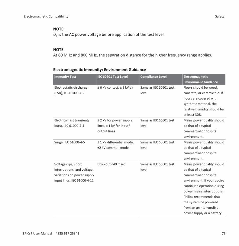
NOTEUT is the AC power voltage before application of the test level.
NOTEAt 80 MHz and 800 MHz, the separation distance for the higher frequency range applies.
Electromagnetic Immunity: Environment GuidanceImmunity Test IEC 60601 Test Level Compliance Level Electromagnetic
Environment GuidanceElectrostatic discharge(ESD), IEC 61000-4-2
± 6 kV contact, ± 8 kV air Same as IEC 60601 testlevel
Floors should be wood,concrete, or ceramic tile. Iffloors are covered withsynthetic material, therelative humidity should beat least 30%.
Electrical fast transient/burst, IEC 61000-4-4
± 2 kV for power supplylines, ± 1 kV for input/output lines
Same as IEC 60601 testlevel
Mains power quality shouldbe that of a typicalcommercial or hospitalenvironment.
Surge, IEC 61000-4-5 ± 1 kV differential mode,±2 kV common mode
Same as IEC 60601 testlevel
Mains power quality shouldbe that of a typicalcommercial or hospitalenvironment.
Voltage dips, shortinterruptions, and voltagevariations on power supplyinput lines, IEC 61000-4-11
Drop out <40 msec Same as IEC 60601 testlevel
Mains power quality shouldbe that of a typicalcommercial or hospitalenvironment. If you requirecontinued operation duringpower mains interruptions,Philips recommends thatthe system be poweredfrom an uninterruptiblepower supply or a battery.
Electromagnetic Compatibility Safety
EPIQ 7 User Manual 4535 617 25341 75
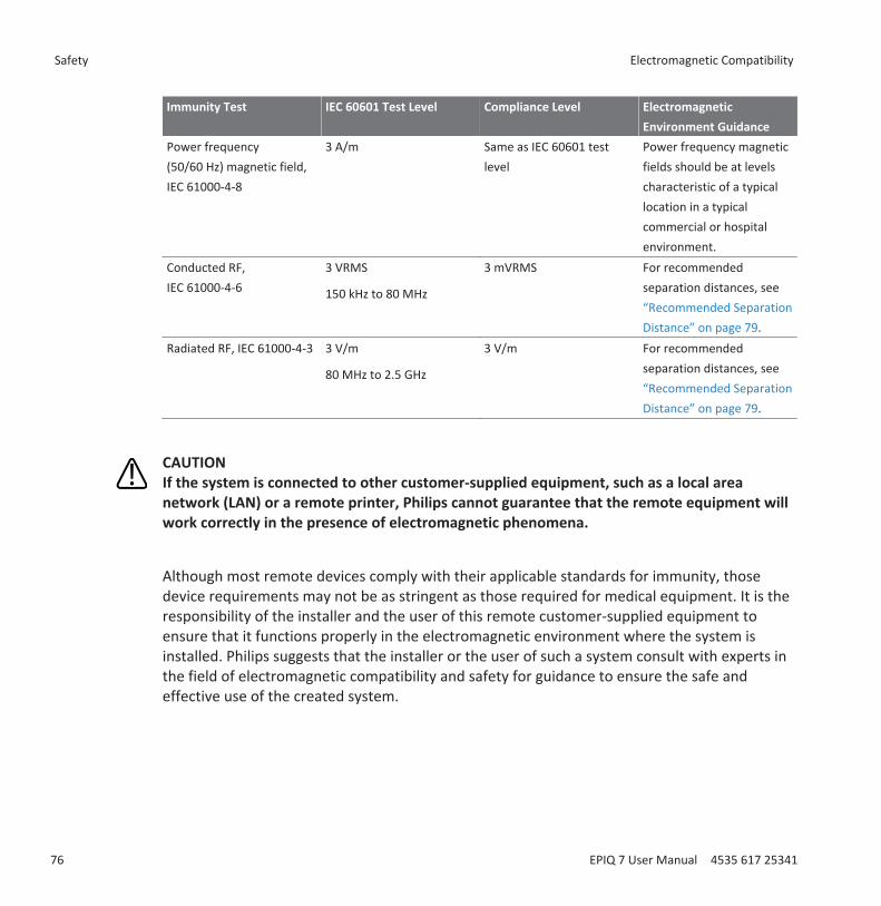
Immunity Test IEC 60601 Test Level Compliance Level ElectromagneticEnvironment Guidance
Power frequency(50/60 Hz) magnetic field,IEC 61000-4-8
3 A/m Same as IEC 60601 testlevel
Power frequency magneticfields should be at levelscharacteristic of a typicallocation in a typicalcommercial or hospitalenvironment.
Conducted RF,IEC 61000-4-6
3 VRMS
150 kHz to 80 MHz
3 mVRMS For recommendedseparation distances, see“Recommended SeparationDistance” on page 79.
Radiated RF, IEC 61000-4-3 3 V/m
80 MHz to 2.5 GHz
3 V/m For recommendedseparation distances, see“Recommended SeparationDistance” on page 79.
CAUTIONIf the system is connected to other customer-supplied equipment, such as a local areanetwork (LAN) or a remote printer, Philips cannot guarantee that the remote equipment willwork correctly in the presence of electromagnetic phenomena.
Although most remote devices comply with their applicable standards for immunity, thosedevice requirements may not be as stringent as those required for medical equipment. It is theresponsibility of the installer and the user of this remote customer-supplied equipment toensure that it functions properly in the electromagnetic environment where the system isinstalled. Philips suggests that the installer or the user of such a system consult with experts inthe field of electromagnetic compatibility and safety for guidance to ensure the safe andeffective use of the created system.
Safety Electromagnetic Compatibility
76 EPIQ 7 User Manual 4535 617 25341
Electromagnetic InterferenceElectromagnetic interference may appear in many ways on the system and depends on themode the equipment is operating in, the imaging control settings, the type of transducer beingused, the type of electromagnetic phenomena, and the intensity level of the phenomena.
CAUTIONWhen interference is present or intermittent, use caution when continuing to use the system.
NOTEElectromagnetic phenomena are not always present and may be transitory in nature. It may beextremely difficult to identify the source of the interference.
NOTEThe following table describes a few typical interferences seen in imaging systems. It isimpossible to describe all manifestations of interference, because it depends on manyparameters of the transmitting device, such as the type of modulation used by the signalcarrier, the source type, and the transmitted level. It is also possible for the interference todegrade the imaging system's performance and not be visible in the image. If the diagnosticresults are suspicious, other means should be used to confirm the diagnosis.
Electromagnetic Compatibility Safety
EPIQ 7 User Manual 4535 617 25341 77
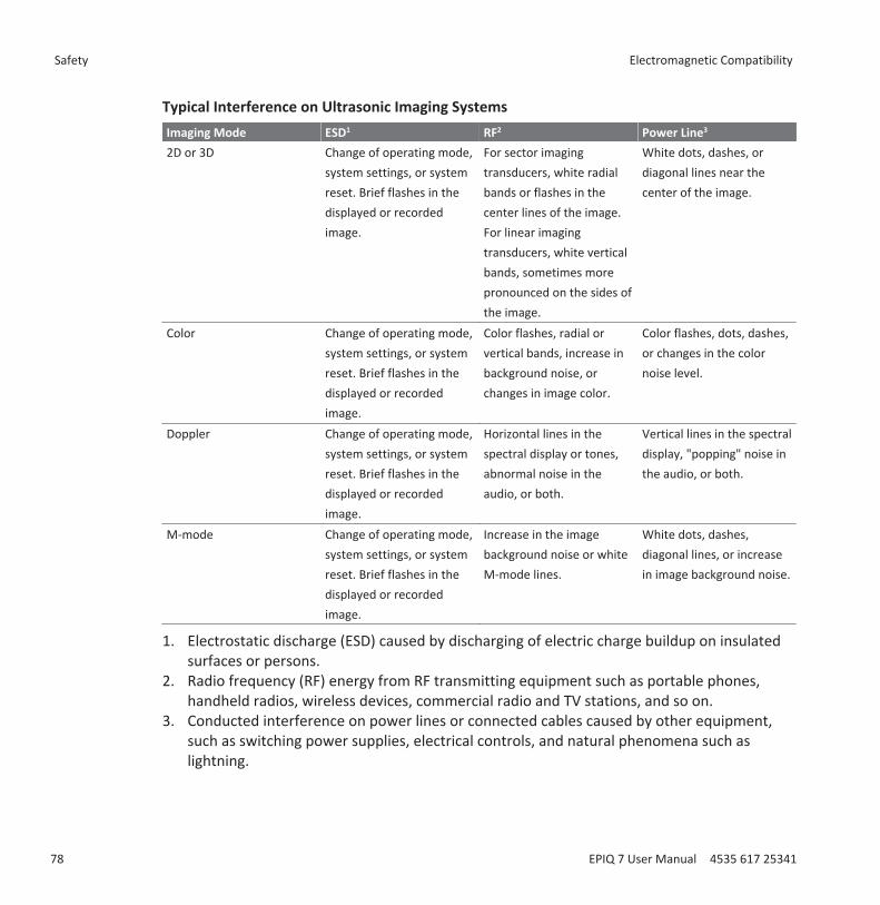
Typical Interference on Ultrasonic Imaging SystemsImaging Mode ESD1 RF2 Power Line3
2D or 3D Change of operating mode,system settings, or systemreset. Brief flashes in thedisplayed or recordedimage.
For sector imagingtransducers, white radialbands or flashes in thecenter lines of the image.For linear imagingtransducers, white verticalbands, sometimes morepronounced on the sides ofthe image.
White dots, dashes, ordiagonal lines near thecenter of the image.
Color Change of operating mode,system settings, or systemreset. Brief flashes in thedisplayed or recordedimage.
Color flashes, radial orvertical bands, increase inbackground noise, orchanges in image color.
Color flashes, dots, dashes,or changes in the colornoise level.
Doppler Change of operating mode,system settings, or systemreset. Brief flashes in thedisplayed or recordedimage.
Horizontal lines in thespectral display or tones,abnormal noise in theaudio, or both.
Vertical lines in the spectraldisplay, "popping" noise inthe audio, or both.
M-mode Change of operating mode,system settings, or systemreset. Brief flashes in thedisplayed or recordedimage.
Increase in the imagebackground noise or whiteM-mode lines.
White dots, dashes,diagonal lines, or increasein image background noise.
1. Electrostatic discharge (ESD) caused by discharging of electric charge buildup on insulatedsurfaces or persons.
2. Radio frequency (RF) energy from RF transmitting equipment such as portable phones,handheld radios, wireless devices, commercial radio and TV stations, and so on.
3. Conducted interference on power lines or connected cables caused by other equipment,such as switching power supplies, electrical controls, and natural phenomena such aslightning.
Safety Electromagnetic Compatibility
78 EPIQ 7 User Manual 4535 617 25341
Recommended Separation DistanceThe following table provides recommended separation distances, which are guidelines on thedistances that any RF transmitting equipment should be kept away from the ultrasound systemto reduce the risk of interference with the system. Portable and mobile RF communicationsequipment should be used no closer to any part of the system, including cables, than therecommended separation distance calculated from the equation applicable to the frequency ofthe transmitter. Field strengths from fixed RF transmitters, as determined by anelectromagnetic site survey, should be less than the compliance level in each frequency rangeas noted in the table. Interference may occur in the vicinity of equipment marked with the
following symbol: .
Field strengths from fixed transmitters, such as base stations for radio (cellular/cordless)telephones and land mobile radios, amateur radio, AM and FM radio broadcast, and TVbroadcast, cannot be predicted theoretically with accuracy. To assess the electromagneticenvironment due to fixed RF transmitters, an electromagnetic site survey should be considered.If the measured field strength in the location in which the system is used exceeds the applicableRF compliance level in the table, the system should be observed to verify normal operation. Ifabnormal performance is observed, additional measures may be necessary, such as reorientingor relocating the system.
NOTEFor transmitters rated at a maximum output power not listed in the following table, therecommended separation distance d in meters (m) can be estimated using the equationapplicable to the frequency of the transmitter, where P is the maximum output power rating ofthe transmitter in watts (W) according to the transmitter manufacturer.
NOTEAt 80 MHz and 800 MHz, the higher frequency range applies.
Electromagnetic Compatibility Safety
EPIQ 7 User Manual 4535 617 25341 79

NOTEThe recommended separation distance guidelines in the following table may not apply to allsituations. Electromagnetic propagation is affected by absorption and reflection fromstructures, objects, and people.
The information provided here, in conjunction with “Electromagnetic Interference” on page 77,provides guidance on conducted and radiated interference from portable and fixed RFtransmitting equipment.
Recommended Separation Distances by Transmitter Frequency
Rated Maximum OutputPower of Transmitter (Watts)
150 kHz to 80 MHz 80 to 800 MHz 800 MHz to 2.5 GHz
0.01 117 m (384 ft) 0.12 m (4.7 in) 0.24 m (9.5 in)
0.1 369 m (1210 ft) 0.38 m (15 in) 0.76 m (30 in)
1 1170 m (3840 ft) 1.2 m (3.9 ft) 2.4 m (7.9 ft)
10 3690 m (12100 ft) 3.8 m (12.5 ft) 7.6 m (25 ft)
100 11700 m (34800 ft) 12 m (39.4 ft) 24 m (78.7 ft)
The conducted RF test level is 3 V, and the system has a compliance level of 3 mV. For thesystem, this means that the imaging system is extremely sensitive to RF interference in thetransducer passband. For example, for a 5-MHz imaging transducer, the frequency range ofinterference from a 3-V/m field may be from 2 to 10 MHz and manifest itself as described in“Electromagnetic Interference” on page 77.
The 0.3 mV level is where the interference becomes acceptable to some clinical specialists.
Sensitivity to interference is dependent on operating mode and imaging control settings. Theorder of increasing sensitivity to interference as a function of operating mode is 2D mode, 3Dmode, M-mode, Color mode, PW Doppler mode, and CW Doppler mode. The system is moresensitive to interference in the CW Doppler or PW Doppler operating modes, but the
Safety Electromagnetic Compatibility
80 EPIQ 7 User Manual 4535 617 25341
probability of interference is lower than in 2D mode or Color mode, because the susceptiblefrequency range is lower. Therefore, you are more likely to see interference in 2D or Colormodes.
As an example, if a portable transmitter has maximum radiated power of 1 W and an operatingfrequency of 156 MHz, it should only be operated at distances greater than 1.2 m (3.9 ft) fromthe system. Likewise, a 0.01-W Bluetooth wireless LAN device operating at 2.4 GHz should beplaced no closer than 0.24 m (9.5 in) from any part of the system.
Avoiding Electromagnetic InterferenceA medical device can either generate or receive electromagnetic interference. The EMCstandards describe tests for both emitted and received interference. Emission tests deal withinterference generated by the device being tested. Philips ultrasound systems do not generateinterference based on the tests described in the referenced standards.
An ultrasound system is designed to receive signals at radio frequencies and is thereforesusceptible to interference generated by RF energy sources. Examples of other sources ofinterference are medical devices, information technology products, and radio and televisiontransmission towers. Tracing the source of radiated interference can be a difficult task.Customers should consider the following in an attempt to locate the source:• Is the interference intermittent or constant?• Does the interference show up only with one transducer or with several transducers?• Do two different transducers operating at the same frequency have the same problem?• Is the interference present if the system is moved to a different location in the facility?• Can the EMC coupling path be attenuated? For example, placement of a transducer or
printer close to an ECG cable can increase electromagnetic interference. Moving the cableor other medical equipment away from the location of the transducer or printer can resultin reduced electromagnetic interference.
The answers to these questions will help determine if the problem resides with the system orthe scanning environment. After you answer the questions, contact your Philips servicerepresentative.
Use Restrictions Due to InterferenceThe physician must determine if an artifact caused by radiated interference will have a negativeimpact on image quality and the subsequent diagnosis.
Electromagnetic Compatibility Safety
EPIQ 7 User Manual 4535 617 25341 81

WARNINGThe physician must determine if tracking is accurate. Tracking in an untested environment ora location known to cause electromagnetic interference can contribute to inaccurateinformation and possible personal injury.
Safety Electromagnetic Compatibility
82 EPIQ 7 User Manual 4535 617 25341
System OverviewUse this section to acquaint yourself with the ultrasound system and its components.
System CapabilitiesThe EPIQ 7 Ultrasound System is a high-resolution system intended for general imaging,interventional radiology, cardiology, vascular, and OB/GYN applications, and analysis. The cartis ergonomically designed to be both highly mobile and adjustable for a range of users andoperating conditions. You can use it for 2D, Live 3D Echo, M-mode, Doppler, and Color imaging.You can also perform Duplex, Triplex, and Live xPlane imaging. Stress echocardiography isstandard on the system, and QLAB Advanced Quantification Software Q-Apps are available asoptions. The system supports a wide range of transducers. The system provides measurementtools, analysis options, and DICOM network capabilities.
MeasurementsThe system provides tools and controls for measuring distance, area, and volume. Additionally,the following application-specific tools are available:• Aliasing Velocity• 3D Volume• Generic Angle• Heart Rate• High Q automatic Doppler analysis• Hip Tools• Percent Reduction• Simpson's Method• Time/Slope• Velocity• Volume Flow
After you perform measurements, the system makes the pertinent calculations and organizesthe measurements, calculations, and patient information into a patient report.
For information, see the Help. To display the Help, touch . To close the Help, touch again.
3
System Capabilities System Overview
EPIQ 7 User Manual 4535 617 25341 83
Transducer TypesAvailable transducer types include sector array, linear array, curved array, Doppler probes,endocavity, intraoperative, transesophageal, volume, and xMATRIX. Applications for specifictransducers are listed in “Clinical Applications and Transducers” on page 174.
Image Acquisition and ReviewYou can acquire and review single images and cineloop sequences. Images and cineloopsequences can be stored on DVDs, CDs, or USB devices, or sent over a network to an archiveserver or a printer.
Stress Echo capabilities also use the ability to acquire and review image loops. Stress Echoprotocols of up to 10 stages are used to assess cardiac wall motion at various heart rates.
Peripheral devices are available for recording images and exams. You can connect a black-and-white image printer or a color image printer. You can also connect a report printer.
Patient Data ProtectionThe data security feature, if enabled on your system, limits access to previously stored patientdata and images. To gain access to such data, you must first log on to the system using apassword. When you are finished using the system, you can log off manually, or you can simplyshut down the system, which logs you off automatically. The system stores a record of eachuser logon.
This data protection feature can be used to help meet the requirements of the U.S. HealthInsurance Portability and Accountability Act (HIPAA).
For more information on protecting patient data, see “System Security” on page 133.
System OptionsIn addition to the standard features available in the system, other features are available aspurchasable options. The types of options available include clinical applications, QLABAdvanced Quantification Software, protocols, imaging capabilities, and connectivity capabilities.A foot switch is available as an option.
System Overview System Capabilities
84 EPIQ 7 User Manual 4535 617 25341

Imaging Options• 3D/4D (mechanical transducers)• 3D Single Sweep Color Flow• 3D Fetal Echo STIC• Auto Doppler Optimization• Color for 3D imaging• Contrast perfusion• Strain Elastography• ElastPQ Shear Wave Elastography• Exam protocols• Freehand 3D• iSCAN Intelligent Optimization• Live 3D and xPlane imaging (xMATRIX transducers)• Panoramic 2D imaging• Panoramic 3D imaging• Physio• Sleep/Portability Mode (Battery Option)• Stress Echo protocols• Tissue Doppler Imaging (TDI)
NOTEThe elastography feature is available only in selected regions. For information specific to yourregion, contact your local Philips representative.
Connectivity CapabilitiesThe following features are standard:• Image and waveform export to removable media• Printing to DICOM printers• Printing to local printers• Printing report pages• Wireless DICOM transfer
System Options System Overview
EPIQ 7 User Manual 4535 617 25341 85
In addition to those standard features, the Basic Connectivity purchasable option includes thefollowing features:• DICOM Networking• Image and waveform export to network storage servers• DICOM Modality Worklist• DICOM Performed Procedure Step (PPS)• DICOM Storage Commit (SC)• DICOM Structured Reporting• DICOM Query/Retrieve• Digital Navigation Link (DNL)
Clinical/Analysis Applications
Clinical applications are available on the system as separate purchasable options. The followingclinical applications and their presets (for example, small parts superficial) are associated withspecific transducers:• Abdominal• Adult Echo• Fetal Echo• General• GYN• Intervention CV• Intervention GI• Musculoskeletal• OB• Pediatric Echo• Pediatric GI• Small Parts• TCD• Urology• Vascular
QLAB Advanced Quantification Software OptionsThe following QLAB Q-Apps are supported for use on your ultrasound system:
System Overview System Options
86 EPIQ 7 User Manual 4535 617 25341

NOTEThe EA Q-App is only available in the United States.
NOTEThe EQ Q-App is not available in the United States.
• Auto 2D Quantification (a2DQ)• Auto Cardiac Motion Quantification (aCMQ)• Cardiac 3D Quantification (Cardiac 3DQ)• Cardiac 3D Quantification Advanced (Cardiac 3DQ Advanced)• Cardiac Motion Quantification Stress (CMQ-Stress)• Elastography Analysis (EA)• Elastography Quantification (EQ)• Fetal Heart Navigator (FHN)• General Imaging 3D Quantification (GI3DQ)• Intima Media Thickness (IMT)• MicroVascular Imaging (MVI)• Mitral Valve Navigator (MVN)• Region of Interest Quantification (ROI)• Strain Quantification (SQ)
Stress EchocardiographyStress Echocardiography (Stress Echo) is a protocol-driven study that allows a cardiologist toassess cardiac wall motion at various heart rates by acquiring views of the heart at differentstages of the study. Stress Echo includes these Philips protocols:• Exercise 2-Stage• Exercise 3-Stage• iRotate Stress• Pharmacological 4-Stage• Quantitative 4-Stage• Wall Motion and Contrast
You can create custom presets based on those protocols.
System Options System Overview
EPIQ 7 User Manual 4535 617 25341 87
Data SecurityA data security feature is available to help maintain the confidentiality of archived patient files.With this option, access to patient exam files is restricted to authorized personnel through userID and password protection. For more information, see “System Security” on page 133.
PercuNav Image Fusion and Interventional NavigationYou can use the PercuNav Image Fusion and Interventional Navigation option to fuse diagnosticimages and guide tracked instruments to targets that have been defined by a physician. Thetarget can be indicated either pre-procedurally or intra-procedurally, either using images orrelative to an indicated position on the patient.
Features include the following:• Multiple applications: The PercuNav option supports multiple applications and can be used
for ablations, biopsies, and other diagnostic and guidance procedures.• Multiple modalities: The PercuNav option works with images from multiple modalities,
including but not limited to CT, MR, PET, ultrasound, and rotational fluoroscopy.
Instructions for using PercuNav are in the PercuNav User Manual.
NOTEPercuNav is a purchasable licensed option. Its user interface is available only when thePercuNav license is enabled.
System ComponentsThe system is housed in an ergonomic cart. The cart is adjustable to accommodate a wide rangeof operator heights and operating positions. Adjustable components can be locked in place sothe cart can be safely moved. The major components include the monitor, control module,On/Off switch, DVD+RW drive, peripheral bay, transducer receptacles, ECG/physio receptacles,USB ports, brakes and steering locks, and foot switch receptacle.
System Overview System Options
88 EPIQ 7 User Manual 4535 617 25341
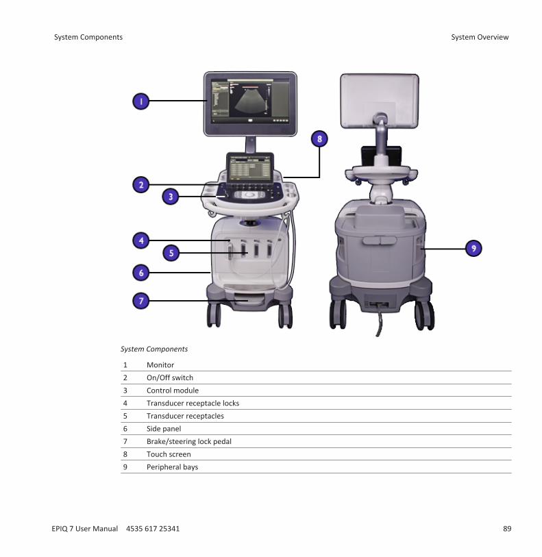
System Components
1 Monitor2 On/Off switch3 Control module4 Transducer receptacle locks5 Transducer receptacles6 Side panel7 Brake/steering lock pedal8 Touch screen9 Peripheral bays
System Components System Overview
EPIQ 7 User Manual 4535 617 25341 89
Video MonitorThe system video monitor consists of a 53.3-cm (21-in) flat-panel display on an articulatedmounting arm. The monitor is adjustable to accommodate different operating positions andoperator heights. The monitor can also be locked in position for moving the system (see“Moving the System” on page 106).
Control ModuleThe control module includes three main components: the control panel, the touch screen, andthe keyboard. For more information on the control module, refer to “System Controls” on page119.
The control panel contains the main imaging controls. These controls include buttons, knobs,and a trackball. The control module also allows you to select transducers, enter patient data,review and annotate images, perform measurements and calculations, and change setups.
The touch screen, located above the control panel, displays controls used to select applicationsand imaging modes, as well as controls that are specific to the current operating mode. Touchscreen controls include buttons and knobs.
System Overview System Components
90 EPIQ 7 User Manual 4535 617 25341
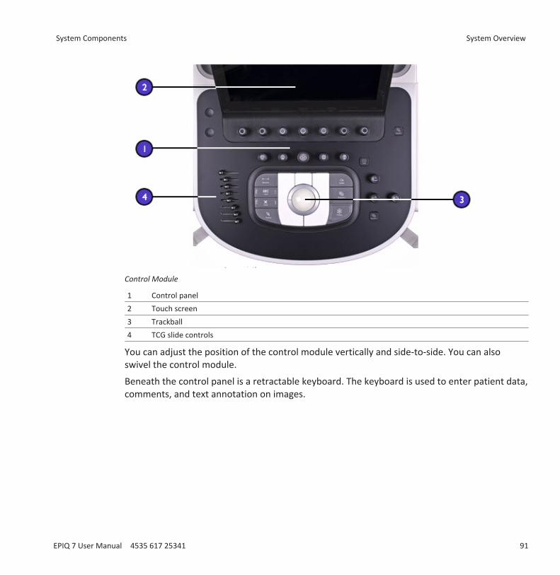
Control Module
1 Control panel2 Touch screen3 Trackball4 TCG slide controls
You can adjust the position of the control module vertically and side-to-side. You can alsoswivel the control module.
Beneath the control panel is a retractable keyboard. The keyboard is used to enter patient data,comments, and text annotation on images.
System Components System Overview
EPIQ 7 User Manual 4535 617 25341 91
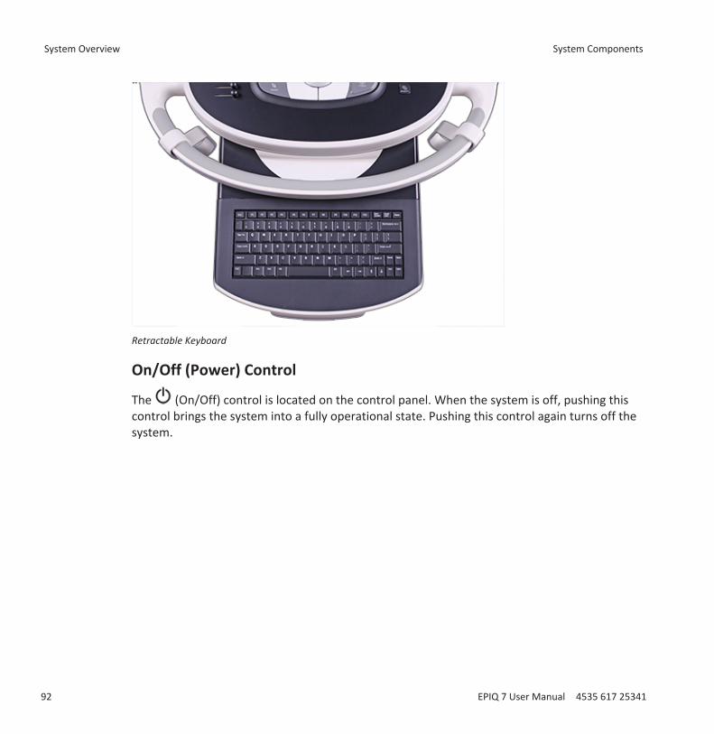
Retractable Keyboard
On/Off (Power) Control
The (On/Off) control is located on the control panel. When the system is off, pushing thiscontrol brings the system into a fully operational state. Pushing this control again turns off thesystem.
System Overview System Components
92 EPIQ 7 User Manual 4535 617 25341
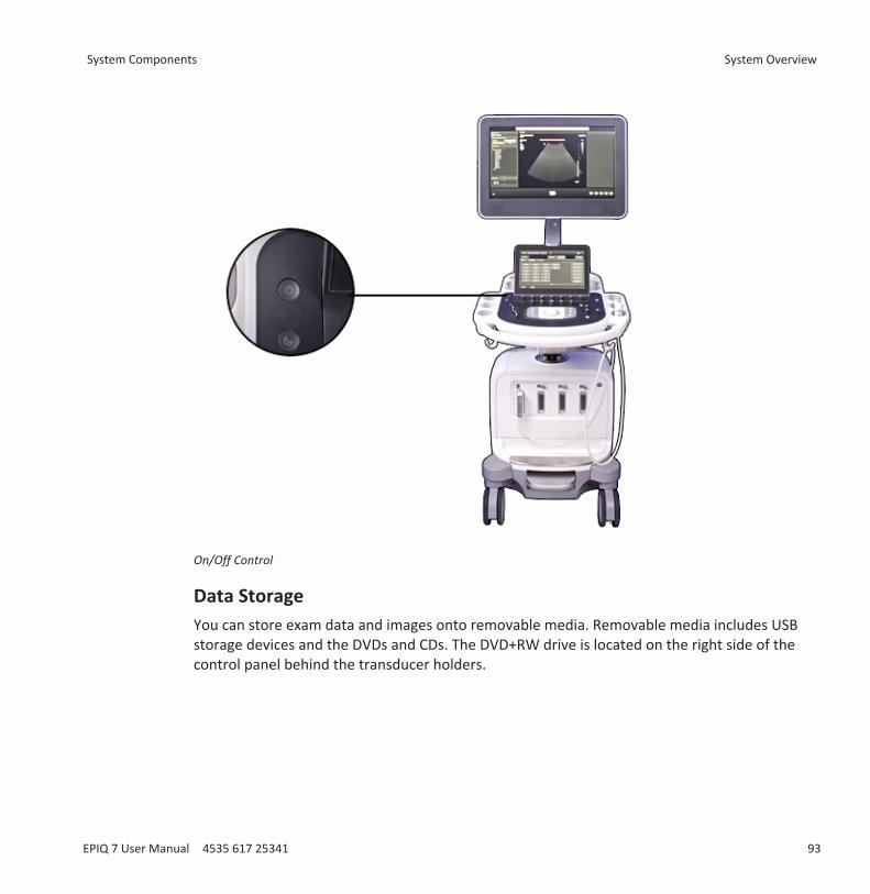
On/Off Control
Data Storage You can store exam data and images onto removable media. Removable media includes USBstorage devices and the DVDs and CDs. The DVD+RW drive is located on the right side of thecontrol panel behind the transducer holders.
System Components System Overview
EPIQ 7 User Manual 4535 617 25341 93
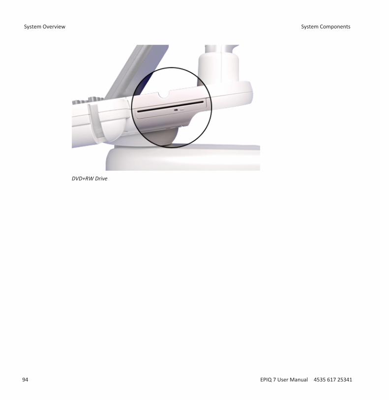
DVD+RW Drive
System Overview System Components
94 EPIQ 7 User Manual 4535 617 25341
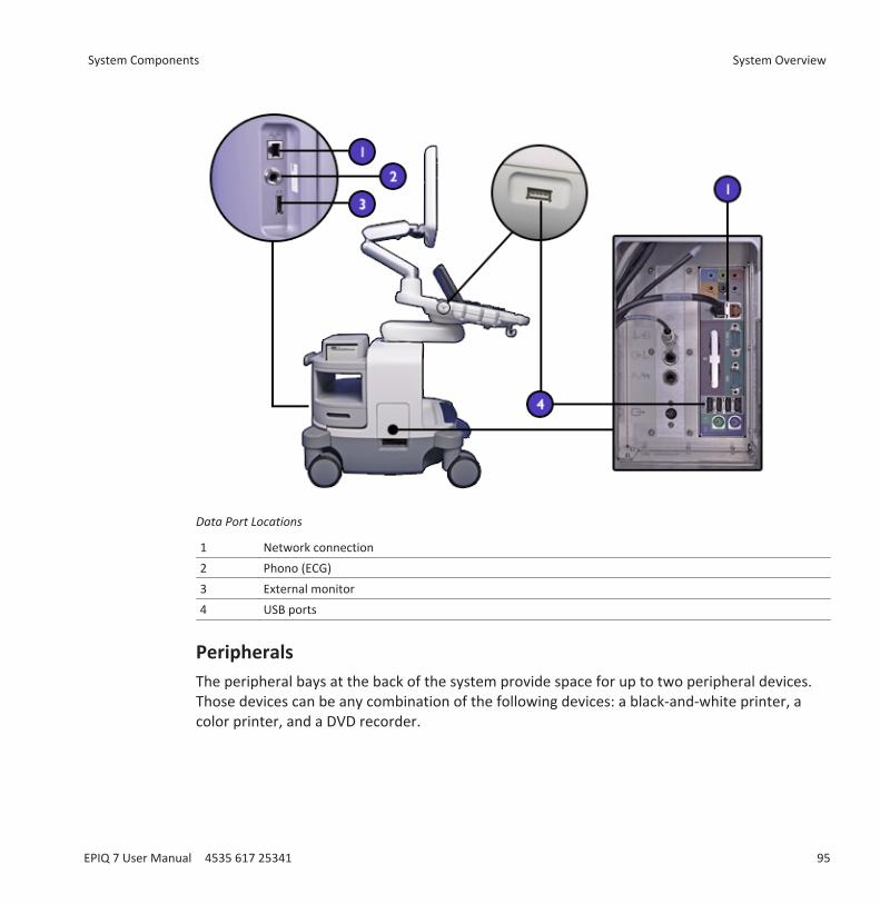
Data Port Locations
1 Network connection2 Phono (ECG) 3 External monitor 4 USB ports
Peripherals
The peripheral bays at the back of the system provide space for up to two peripheral devices.Those devices can be any combination of the following devices: a black-and-white printer, acolor printer, and a DVD recorder.
System Components System Overview
EPIQ 7 User Manual 4535 617 25341 95
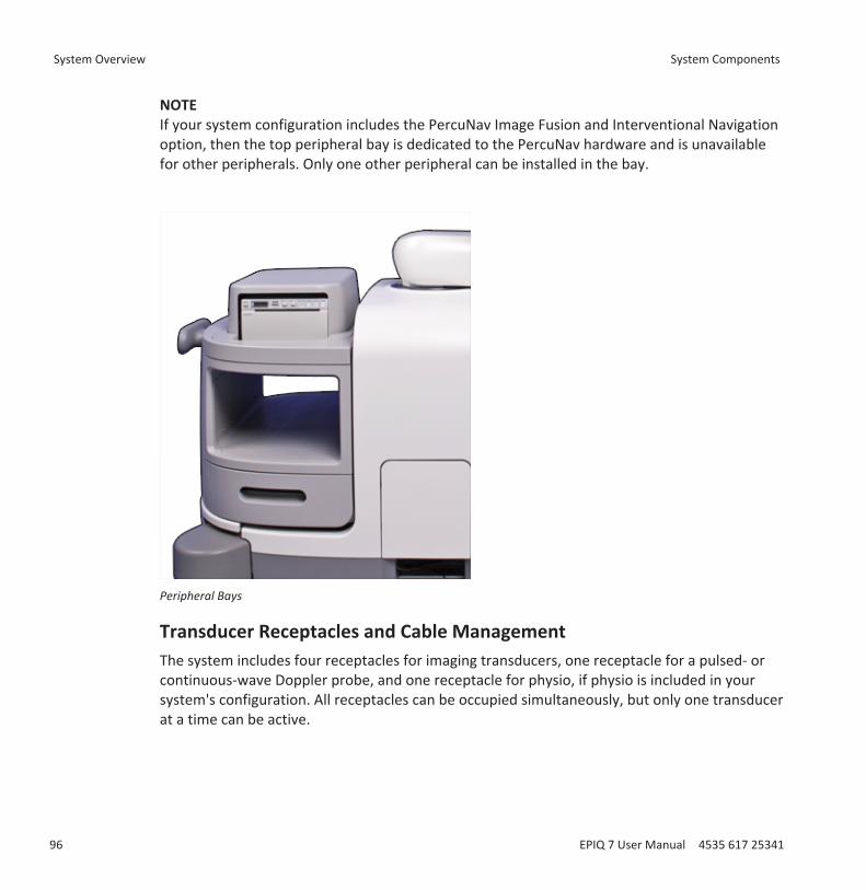
NOTEIf your system configuration includes the PercuNav Image Fusion and Interventional Navigationoption, then the top peripheral bay is dedicated to the PercuNav hardware and is unavailablefor other peripherals. Only one other peripheral can be installed in the bay.
Peripheral Bays
Transducer Receptacles and Cable ManagementThe system includes four receptacles for imaging transducers, one receptacle for a pulsed- orcontinuous-wave Doppler probe, and one receptacle for physio, if physio is included in yoursystem's configuration. All receptacles can be occupied simultaneously, but only one transducerat a time can be active.
System Overview System Components
96 EPIQ 7 User Manual 4535 617 25341
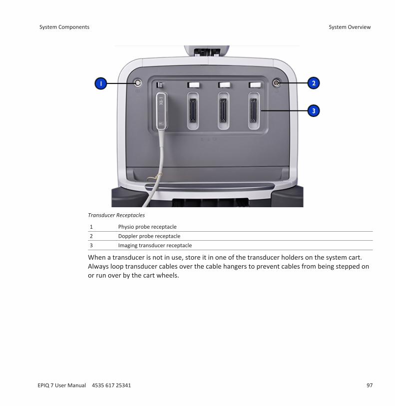
Transducer Receptacles
1 Physio probe receptacle2 Doppler probe receptacle3 Imaging transducer receptacle
When a transducer is not in use, store it in one of the transducer holders on the system cart.Always loop transducer cables over the cable hangers to prevent cables from being stepped onor run over by the cart wheels.
System Components System Overview
EPIQ 7 User Manual 4535 617 25341 97
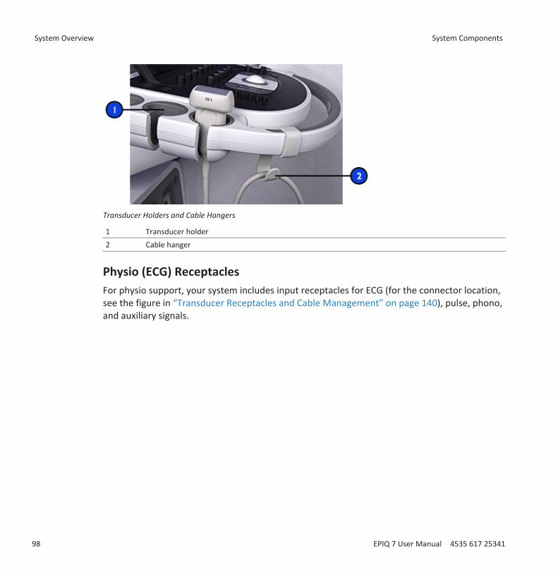
Transducer Holders and Cable Hangers
1 Transducer holder2 Cable hanger
Physio (ECG) ReceptaclesFor physio support, your system includes input receptacles for ECG (for the connector location,see the figure in “Transducer Receptacles and Cable Management” on page 140), pulse, phono,and auxiliary signals.
System Overview System Components
98 EPIQ 7 User Manual 4535 617 25341

ECG and Physio Receptacles
1 Physio out2 Pulse/Phono/Aux 2 input3 Physio input4 S-VHS output
Wheel Brakes and Steering LocksThe system includes brakes that you can engage to help keep the system stationary during use.You can release the brakes and engage steering locks on the front wheels to aid in steeringwhile moving the system, or you can release all locks, which allows all wheels to move freely.When the pedal is fully pressed down, all brakes are engaged. To release all brakes, move thepedal to the middle position. To engage the steering locks, pull the pedal fully up.
For more information, see “Using the Brakes and Steering Locks” on page 115.
System Components System Overview
EPIQ 7 User Manual 4535 617 25341 99
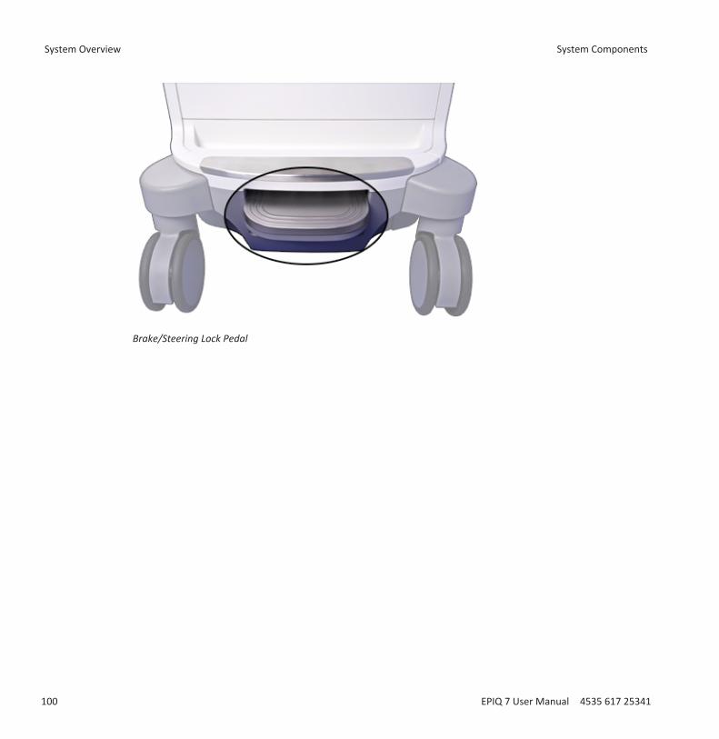
Brake/Steering Lock Pedal
System Overview System Components
100 EPIQ 7 User Manual 4535 617 25341
Preparing the SystemThe information and procedures in this section will help you prepare the system for use.Preparations include connecting transducers and external devices, locking articulatedcomponents for moving, and ensuring that system operating requirements are met.
Connecting DevicesIn addition to the devices installed in the system cart, the system supports external devices.These devices include printers, a foot switch, and a color monitor.
The system also supports a DVD recorder. This recorder is considered an external device, evenwhen it is installed on the system. The DVD recorder can be installed before the system isshipped, or it can be installed later by your Philips representative.
WARNINGWhen using additional peripheral equipment powered from an electrical source other thanthe ultrasound system, the combination is considered to be a medical system. It is yourresponsibility to comply with IEC 60601-1 and test the system to those requirements. If youhave questions, contact your Philips representative.
WARNINGDo not use nonmedical peripherals, such as report printers, within 1.5 m (5 ft) of a patient,unless the nonmedical peripherals receive power from an isolation transformer that meetsmedical safety standards, as defined by standard IEC 60601-1.
WARNINGPhilips ultrasound systems are tested to the requirements of IEC 60601-1, with on-cartperipherals that are powered by the built-in system isolation. The system peripherals meetgeneral electrical safety usage requirements.
4
Connecting Devices Preparing the System
EPIQ 7 User Manual 4535 617 25341 101
WARNINGOff-cart devices connecting to the ultrasound system must comply with the applicable IEC ornational standards, such as IEC 60601-1, IEC 60950, or the equivalent.
CAUTIONUsing accessories, transducers, peripherals, or cables not supplied with the ultrasoundsystem or recommended by Philips can affect the system in the form of increased emissionsor decreased immunity to external EMI/EMC occurrences. Non-specified peripherals, andcables in some cases, can also increase leakage current or compromise the safety of thegrounding scheme.
CAUTIONIf systems, transducers, and peripherals have been in an environment below 10°C (50°F),allow them to reach room temperature before connecting or turning them on. Philipsrecommends allowing 24 hours for complete normalization. Otherwise, condensation insidethe devices could cause damage. If the device was only briefly exposed to temperaturesbelow 10°C (50°F), then the time required for the device to return to room temperature couldbe significantly less than 24 hours.
NOTEAny device that is not purchased from Philips or a Philips-authorized agent is not covered undera Philips service agreement or warranty.
External PrintersYou can connect different external printers to your system.
WARNINGImages printed on a report printer are intended only for reference and should not be used fordiagnostic purposes.
Preparing the System Connecting Devices
102 EPIQ 7 User Manual 4535 617 25341
NOTEUse only the printers listed here with your ultrasound system.
NOTEThe system uses the HP Universal Print Driver and the Epson Universal Print Driver, whichsupport additional printers not listed here. For the supported printers, see the manufacturer'swebsite and search for "universal print driver."
Supported External PrintersPrinter Type Printer Manufacturers and Model NumbersBlack-and-white imageprinter
Sony UP-D897/SYN
Color printer Sony UP-D25MD
Connecting an External Printer
WARNINGWhen using additional peripheral equipment powered from an electrical source other thanthe ultrasound system, the combination is considered to be a medical system. It is yourresponsibility to comply with IEC 60601-1 and test the system to those requirements. If youhave questions, contact your Philips representative.
WARNINGDo not use nonmedical peripherals, such as report printers, within 1.5 m (5 ft) of a patient,unless the nonmedical peripherals receive power from an isolation transformer that meetsmedical safety standards, as defined by standard IEC 60601-1.
1. Turn off the system and unplug the power cord from the power source.
2. Connect a standard USB cable between the USB port on the printer and a USB porton the system.
Connecting Devices Preparing the System
EPIQ 7 User Manual 4535 617 25341 103
3. Connect the printer’s power cord into the back of the printer, and plug the other end intoan appropriate power source (see “Warnings” on page 16).
4. Plug the system's power cord into an appropriate power source.5. Turn on the printer, and then turn on the system. The system installs the printer drivers
automatically.6. After the system installs the new printer drivers, restart the system.
Configuring Local PrintersYou can add a local printer to the system and then, in the setups, associate it with either atouch screen control or the Acquire 1 or Acquire 2 control. You can print only to a printer thathas been selected. You can also change other printing parameters.
WARNINGMulti-image prints made on small-size paper are intended only for reference and should notbe used for diagnostic purposes. Text annotation and scaling markers may not be visible onsuch prints.
NOTEBefore adding a local printer, connect the printer to the ultrasound system.
1. Touch Utilities.2. On the System tab, touch Setups.3. Click Acquisition/Capture.4. Click the Archive/Printer tab.5. To assign a printer to the Acquire 1 or the Acquire 2 control, do the following:
a. From the Acquisition Type list, select a type.b. Select the printer that you want to use.
6. To assign a printer to a touch screen control, do the following:a. Under Select a Touch Screen Button, select the name of the control that you want to
assign.b. In Destination(s) for the Button, select a printer.
7. To exit the setups, touch Close.
Preparing the System Connecting Devices
104 EPIQ 7 User Manual 4535 617 25341
Connecting the Foot SwitchThe foot switch is available as an option.1. Turn off the system.2. Connect the foot switch cable to an available USB connector on the system.
Connecting an External DVD RecorderYou can connect the Sony DVO–1000MD DVD Recorder to your ultrasound system as anexternal device.
The external DVD recorder record from the ultrasound system; it does not provide playback onthe system monitor. The DVD recorder must be installed with the Philips DVD recorderinstallation kit. (For the kit, contact your Philips representative.) If you connect this DVDrecorder without the installation kit or connect any other DVD recorder, you must control itfrom the front panel controls on the DVD recorder or the remote controls supported by theDVD recorder. The remote controls DSRM‑10 or SVRM‑100A provide a convenient way tocontrol the external DVD recorder.1. Turn off the system and unplug the power cord from the power source.2. Connect an S-Video cable between the S-Video input on the DVD recorder and the S-Video
output on the ultrasound system.3. Connect the DVD recorder's power cord into the back of the DVD recorder, and plug the
other end into an appropriate power source.4. Turn on the DVD recorder, and then turn on the ultrasound system.
Connecting an External Color MonitorYou can connect a compatible external color monitor to the receptacle on the rear panel ofthe system. This receptacle provides standard DisplayPort digital output. You also can connect
an external analog monitor to the (S-Video) receptacle. A digital monitor connected to theDisplayPort receptacle provides the best-quality image. The power cord for the externalmonitor plugs directly into a wall socket.
For monitors and video projectors requiring other connectors, such as VGA or DVI, a converteris required.
Connecting Devices Preparing the System
EPIQ 7 User Manual 4535 617 25341 105
The DisplayPort output includes the entire display. The aspect ratio of the screen is 16:9. Todisplay this properly, select the 16:10 or 16:9 mode on the monitor or projector, if available.Also, you may be able to adjust the horizontal and vertical image size controls to create thecorrect aspect ratio. You can best judge the aspect ratio by displaying the circle test pattern onthe system.
The setups provide these outputs:
Full Screen, 1920x1080 (1080p): The full display, which is output at 60 frames per second onthe DisplayPort connector. When this option is selected, you cannot use the S-video output.
Image Area Only,1024x768: Outputs the region of interest of the image area to the S-Videoconnector in NTSC or PAL format (depending on the system setting).
Connecting the System to a NetworkFor information on changing the network configuration for the system, see "System
Administration" in the Help. To display the Help, touch . To close the Help, touch again ortouch Close.1. Turn off system power.2. Connect one end of the provided network connection cable to the wall receptacle for your
network.3. Connect the other end of the cable to the network receptacle on the system.4. Turn on the system.
Moving the SystemObserve the following warnings and cautions before moving the system.
WARNINGBe aware of the wheels, especially when moving the system. The system could cause injury toyou or others if it rolls over feet or into shins. Use caution when going up or down ramps.
Preparing the System Connecting the System to a Network
106 EPIQ 7 User Manual 4535 617 25341
WARNINGWhen attempting to overcome an obstacle, do not push the system from either side withexcessive force, which could cause the system to tip over.
WARNINGPosition external hardcopy devices away from the system. Ensure that they are secure. Donot stack them on the system.
WARNINGWhen positioning the articulated monitor, move it carefully to avoid pinching hands orextremities against other objects, such as a bed rail.
WARNINGNever park the system on an incline.
WARNINGThe brakes are intended as a convenience. To increase cart security, use wheel chocks whenthe system is parked.
WARNINGBefore moving the system, ensure that the keyboard is retracted, the control panel iscentered, and the monitor is locked. When extended, the keyboard might be damaged if ithits another object, and the video monitor could swing out during transport, causing injury orequipment damage.
WARNINGTo avoid injury, Philips recommends against lifting the system cart.
Moving the System Preparing the System
EPIQ 7 User Manual 4535 617 25341 107
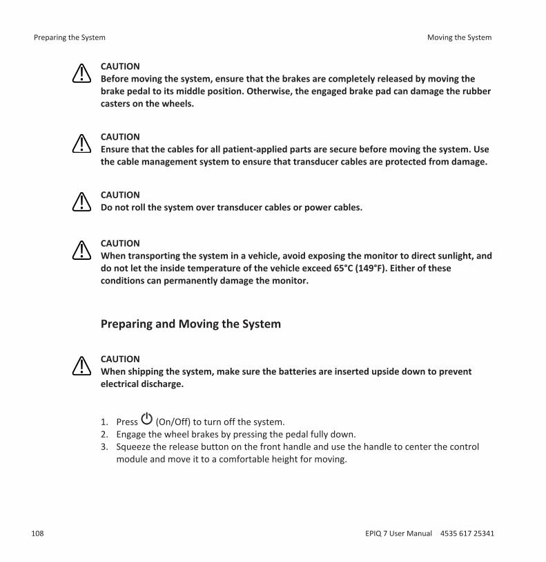
CAUTIONBefore moving the system, ensure that the brakes are completely released by moving thebrake pedal to its middle position. Otherwise, the engaged brake pad can damage the rubbercasters on the wheels.
CAUTIONEnsure that the cables for all patient-applied parts are secure before moving the system. Usethe cable management system to ensure that transducer cables are protected from damage.
CAUTIONDo not roll the system over transducer cables or power cables.
CAUTIONWhen transporting the system in a vehicle, avoid exposing the monitor to direct sunlight, anddo not let the inside temperature of the vehicle exceed 65°C (149°F). Either of theseconditions can permanently damage the monitor.
Preparing and Moving the System
CAUTIONWhen shipping the system, make sure the batteries are inserted upside down to preventelectrical discharge.
1. Press (On/Off) to turn off the system.2. Engage the wheel brakes by pressing the pedal fully down.3. Squeeze the release button on the front handle and use the handle to center the control
module and move it to a comfortable height for moving.
Preparing the System Moving the System
108 EPIQ 7 User Manual 4535 617 25341
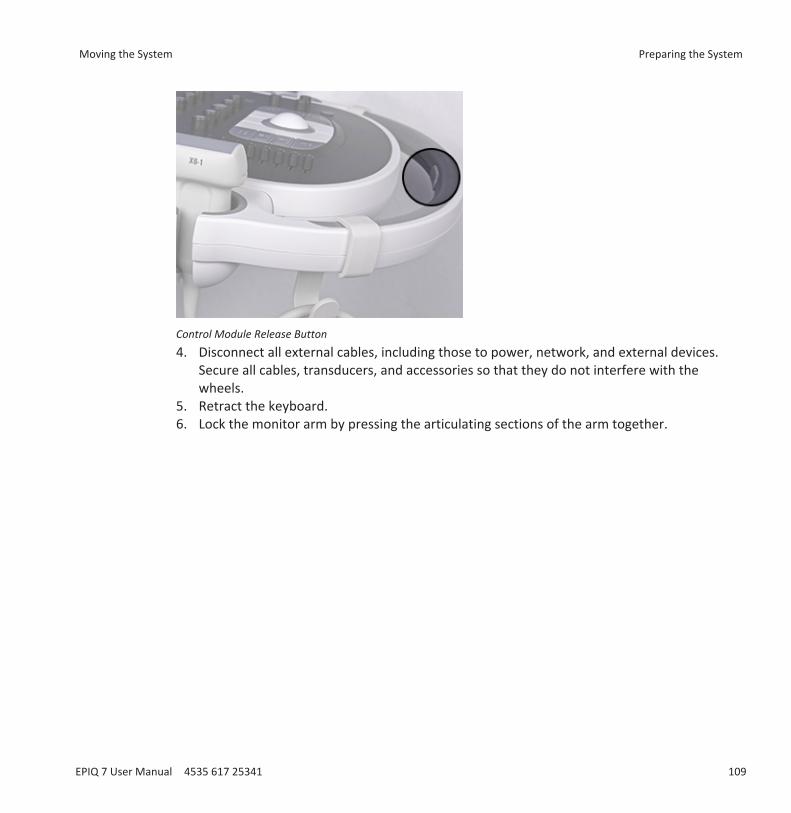
Control Module Release Button4. Disconnect all external cables, including those to power, network, and external devices.
Secure all cables, transducers, and accessories so that they do not interfere with thewheels.
5. Retract the keyboard.6. Lock the monitor arm by pressing the articulating sections of the arm together.
Moving the System Preparing the System
EPIQ 7 User Manual 4535 617 25341 109
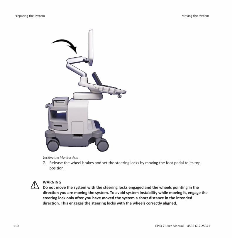
Locking the Monitor Arm7. Release the wheel brakes and set the steering locks by moving the foot pedal to its top
position.
WARNINGDo not move the system with the steering locks engaged and the wheels pointing in thedirection you are moving the system. To avoid system instability while moving it, engage thesteering lock only after you have moved the system a short distance in the intendeddirection. This engages the steering locks with the wheels correctly aligned.
Preparing the System Moving the System
110 EPIQ 7 User Manual 4535 617 25341
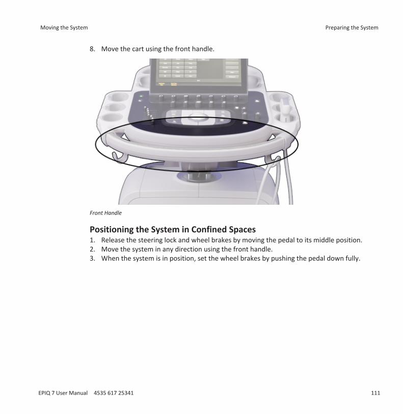
8. Move the cart using the front handle.
Front Handle
Positioning the System in Confined Spaces1. Release the steering lock and wheel brakes by moving the pedal to its middle position.2. Move the system in any direction using the front handle.3. When the system is in position, set the wheel brakes by pushing the pedal down fully.
Moving the System Preparing the System
EPIQ 7 User Manual 4535 617 25341 111
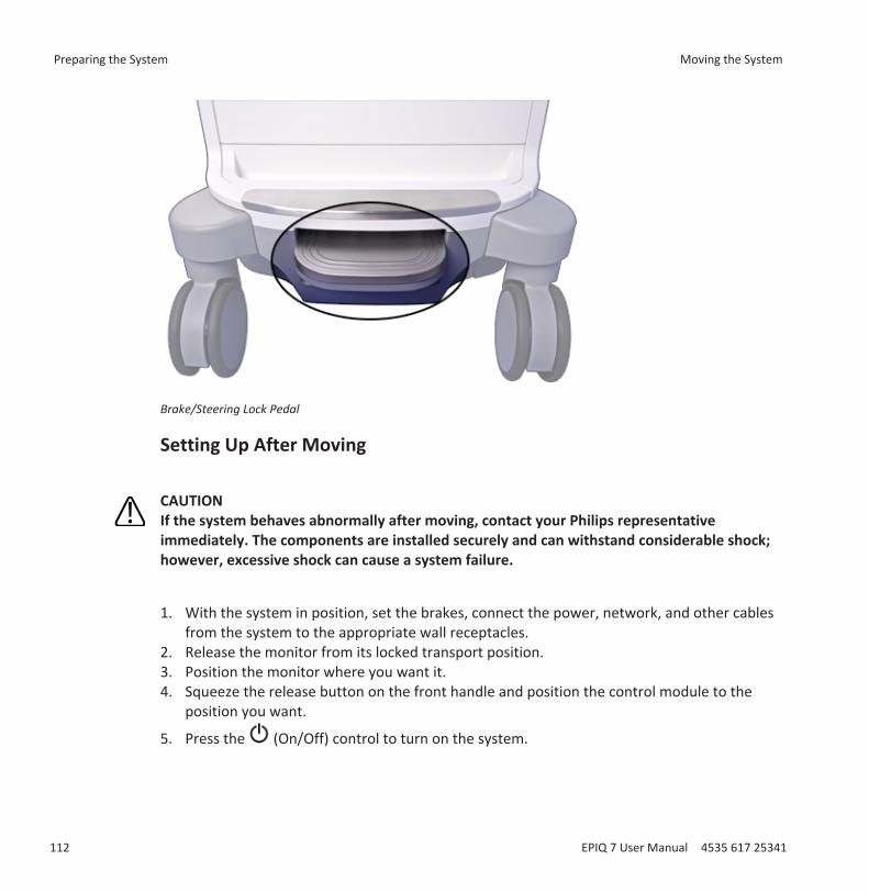
Brake/Steering Lock Pedal
Setting Up After Moving
CAUTIONIf the system behaves abnormally after moving, contact your Philips representativeimmediately. The components are installed securely and can withstand considerable shock;however, excessive shock can cause a system failure.
1. With the system in position, set the brakes, connect the power, network, and other cablesfrom the system to the appropriate wall receptacles.
2. Release the monitor from its locked transport position.3. Position the monitor where you want it.4. Squeeze the release button on the front handle and position the control module to the
position you want.
5. Press the (On/Off) control to turn on the system.
Preparing the System Moving the System
112 EPIQ 7 User Manual 4535 617 25341
Using the SystemThe topics that follow will help you understand and use the features of the system.
Turning the System On and Off
The (On/Off) control is located on the upper left section of the control panel. The lighting ofthe control changes to indicate its status. The different indicators are described in the followingtable.
Power Status and IndicatorsSystem Status Power Cord Status Power Control Indicator Sleep Control IndicatorPower off Disconnected Unlighted UnlightedPower off Connected Lighted white UnlightedPower on Connected Lighted green Lighted whiteSleep Mode on Disconnected Blinking amber UnlightedSleep Mode on Connected Blinking green Unlighted
CAUTION
If you press and hold the (On/Off) control to force the system to shut down, you will haveto wait longer than usual to use your system the next time you turn it on. You may alsocorrupt files, which can result in an inoperative system or the loss of patient data. Wait90 seconds (or 3 minutes if DICOM activity is occurring) before forcing the system to shutdown.
CAUTIONThe batteries are used to ensure quick system startup and easy movement of the systemonly. You cannot perform scans while in battery mode.
5
Turning the System On and Off Using the System
EPIQ 7 User Manual 4535 617 25341 113
NOTEIf battery power is unavailable, or if the battery charge level is critically low, as indicated by the
(low battery power) icon, connect the system power cord to a wall outlet.
NOTEThe system must be connected to a wall outlet to be used for imaging.
1. If you are turning off the system, first close all dialog boxes by clicking Close or Done2. Do one of the following:
• When the system is off, press the (On/Off) control to turn it on.
• When the system is on, press the (On/Off) control to turn it off. A confirmationmessage appears briefly on the display immediately before the system turns off.
3. If the system does not turn off after 90 seconds (or 3 minutes if DICOM activity is
occurring), press and hold the (On/Off) control for 7 to 10 seconds to force the systemto turn off.
4. To break the connection from the main power supply, remove the ultrasound system plugfrom the wall outlet.
Setting the System Time and DateThe system includes a clock/calendar function, which maintains accurate time and date evenwhen the system is turned off and disconnected from power. The system uses the clock/calendar function to display the time and date on the imaging display, and to provide a timestamp on patient studies and acquired images. The system automatically adjusts the date forleap years but does not automatically set the time zone or update for daylight saving time.
NOTEThe system time and date cannot be set when a study is active. It is recommended that youcheck the system time and date periodically before a study, and set the correct time and date,if necessary.
Using the System Setting the System Time and Date
114 EPIQ 7 User Manual 4535 617 25341
NOTEIf you change the system date while a study is paused, existing results for date-dependentcalculations in the paused study are not recalculated by the system at any time.
NOTEWhen you enter invalid characters in the time and date setups on the Header tab of SystemSettings, some characters are displayed and then erased, but others are not displayed at all. Aninvalid date may be displayed in the setups but not entered when you close the setups. Afterchanging a date and exiting the setups, always check the date on the imaging display.
NOTEThis system supports the Network Time Protocol (NTP), which keeps your system's timeaccurate by synching with the NTP server. To activate this feature, your system administratormust create a connection to an NTP server.
1. Touch Utilities.2. On the System tab, touch Setups.3. Click System Settings and then Header.4. In Set Time, select a Format (12 hours or 24 hours), click the time in the Time box to select
it, and then use the number keys to enter the correct setting. Select Am or Pm, if necessary.5. In Set Date, select a Format, click the Date to select it, and then use the number keys to
enter the correct setting.
Using the Brakes and Steering LocksAll four wheels swivel to aid in maneuvering the system. You can engage steering locks to makesteering easier when moving the cart. Brakes help keep the cart stationary while in use. Thebrakes and the steering locks are designed so that they cannot be engaged simultaneously.
Your system has a foot pedal at the lower front of the cart. Operate the brakes and the steeringlocks with the foot pedal using the appropriate procedure.
Using the Brakes and Steering Locks Using the System
EPIQ 7 User Manual 4535 617 25341 115

WARNINGNever park the system on an incline.
WARNINGThe brakes are intended as a convenience. To increase cart security, use wheel chocks whenthe system is parked.
Do any of the following:1 To engage the steering locks and release the brakes, lift the pedal fully.2 To release both the steering locks and the brakes, move the pedal to its middle position.3 To engage the brakes and release the steering locks, press the pedal fully.
Monitor Adjustments
CAUTIONTo avoid damaging the flat-panel display in the monitor, do not operate it in direct sunlight.Also, do not operate or store the system where the ambient temperature exceeds 65°C(149°F).
Using the System Monitor Adjustments
116 EPIQ 7 User Manual 4535 617 25341
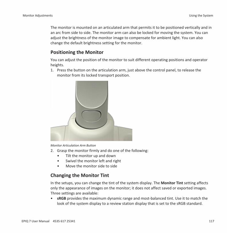
The monitor is mounted on an articulated arm that permits it to be positioned vertically and inan arc from side to side. The monitor arm can also be locked for moving the system. You canadjust the brightness of the monitor image to compensate for ambient light. You can alsochange the default brightness setting for the monitor.
Positioning the MonitorYou can adjust the position of the monitor to suit different operating positions and operatorheights.1. Press the button on the articulation arm, just above the control panel, to release the
monitor from its locked transport position.
Monitor Articulation Arm Button2. Grasp the monitor firmly and do one of the following:
• Tilt the monitor up and down• Swivel the monitor left and right• Move the monitor side to side
Changing the Monitor TintIn the setups, you can change the tint of the system display. The Monitor Tint setting affectsonly the appearance of images on the monitor; it does not affect saved or exported images.Three settings are available:• sRGB provides the maximum dynamic range and most-balanced tint. Use it to match the
look of the system display to a review station display that is set to the sRGB standard.
Monitor Adjustments Using the System
EPIQ 7 User Manual 4535 617 25341 117
• 1 is balanced toward a blue tint for those that have a cooler preference• 2 is balanced toward a brown tint for those that have a warmer preference1. Touch Utilities.2. On the System tab, touch Setups.3. Click System Settings, and then click the Display tab.4. Select the appropriate Default Monitor Tint setting. Philips recommends the sRGB setting
for routine use.5. Click Close.
NOTERendered 3D volumes are particularly susceptible to changes in display tint. Some cliniciansprefer the following settings for optimal viewing of 3D volumes: set Default Monitor Tint to 1or 2 and set Default Monitor Brightness to 1.
You can also change the monitor tint temporarily:1. Touch Utilities.2. On the System tab, touch Monitor Tint to choose from sRGB, 1, or 2.
Changing the Default Monitor BrightnessYou can change the default brightness of the monitor image in the setups. The system uses thisdefault value to set monitor brightness each time the system is turned on.1. Touch Utilities.2. On the System tab, touch Setups.3. Click System Settings, and then click the Display tab.4. Select a setting for Default Monitor Brightness from 1 (darkest) to 6 (lightest).5. Click Close.
You can also change the monitor brightness temporarily:1. Touch Utilities.2. On the System tab, touch Monitor Brightness to choose from 1 (darkest) to 6 (lightest).
Using the System Monitor Adjustments
118 EPIQ 7 User Manual 4535 617 25341
Automatic Display DimmingTo preserve monitor life and prevent burned-in display artifacts, the system automatically dimsthe display after more than 2 hours of operation with no control changes. The system restoresfull brightness as soon as you use any system control.
System ControlsSystem controls are located on the control panel, the touch screen, and the keyboard.
Control PanelThe control panel contains the main imaging controls. These controls include buttons, knobs,TGC slide controls, and a trackball. The control module also allows you to select imaging modes,review and annotate images, perform measurements and calculations, and access PhilipsSupportConnect.
The touch screen, located above the control panel, displays controls used to select transducers,enter patient data, select applications, and change setups.
Monitor Adjustments Using the System
EPIQ 7 User Manual 4535 617 25341 119
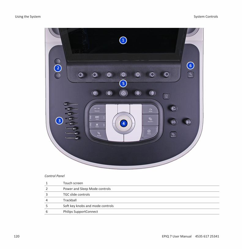
Control Panel
1 Touch screen2 Power and Sleep Mode controls3 TGC slide controls4 Trackball5 Soft key knobs and mode controls6 Philips SupportConnect
Using the System System Controls
120 EPIQ 7 User Manual 4535 617 25341

Control Panel AdjustmentsThe control panel is mounted on an articulated arm that permits it to be positioned verticallyand in an arc from side to side. The control panel arm can also be locked for moving the system.You can adjust the brightness of the control panel to compensate for ambient light. You canalso change the default brightness setting for the control panel.
Adjusting Control Panel BrightnessThe control panel and touch screen brightness controls in the setups allow you to adjust thebrightness of the control panel and touch screen to compensate for changes in ambient light.1. Touch Utilities.2. On the System tab, touch Setups.3. Do one of the following:
• Select System Settings, and click Display. Select a setting for Control Panel Brightness.• Turn the CP Brightness knob, or touch CP Brightness until your preferred brightness is
selected.
Positioning the Control PanelYou can swivel the control panel, move it side-to-side, and move it up and down to improveergonomics.
1. Press the (On/Off) control to turn on the system.2. Push the foot pedal fully down to engage the brakes. See “Using the Brakes and Steering
Locks” on page 115.
CAUTIONYou must engage the brakes to change the position of the control panel. If the brakes are notengaged, the release button on the front handle will light when pressed, but the controlpanel will not unlock.
3. Press the release button on the front handle.
System Controls Using the System
EPIQ 7 User Manual 4535 617 25341 121
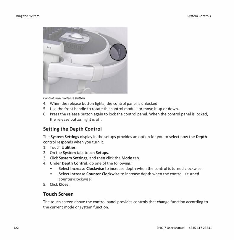
Control Panel Release Button4. When the release button lights, the control panel is unlocked.5. Use the front handle to rotate the control module or move it up or down.6. Press the release button again to lock the control panel. When the control panel is locked,
the release button light is off.
Setting the Depth ControlThe System Settings display in the setups provides an option for you to select how the Depthcontrol responds when you turn it.1. Touch Utilities.2. On the System tab, touch Setups.3. Click System Settings, and then click the Mode tab.4. Under Depth Control, do one of the following:
• Select Increase Clockwise to increase depth when the control is turned clockwise.• Select Increase Counter Clockwise to increase depth when the control is turned
counter-clockwise.5. Click Close.
Touch ScreenThe touch screen above the control panel provides controls that change function according tothe current mode or system function.
Using the System System Controls
122 EPIQ 7 User Manual 4535 617 25341
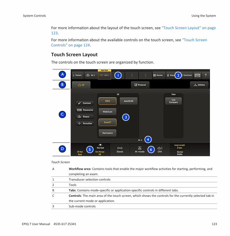
For more information about the layout of the touch screen, see “Touch Screen Layout” on page123.
For more information about the available controls on the touch screen, see “Touch ScreenControls” on page 124.
Touch Screen LayoutThe controls on the touch screen are organized by function.
Touch Screen
A Workflow area: Contains tools that enable the major workflow activities for starting, performing, andcompleting an exam.
1 Transducer selection controls2 ToolsB Tabs: Contains mode-specific or application-specific controls in different tabs.C Controls: The main area of the touch screen, which shows the controls for the currently selected tab in
the current mode or application.3 Sub-mode controls
System Controls Using the System
EPIQ 7 User Manual 4535 617 25341 123
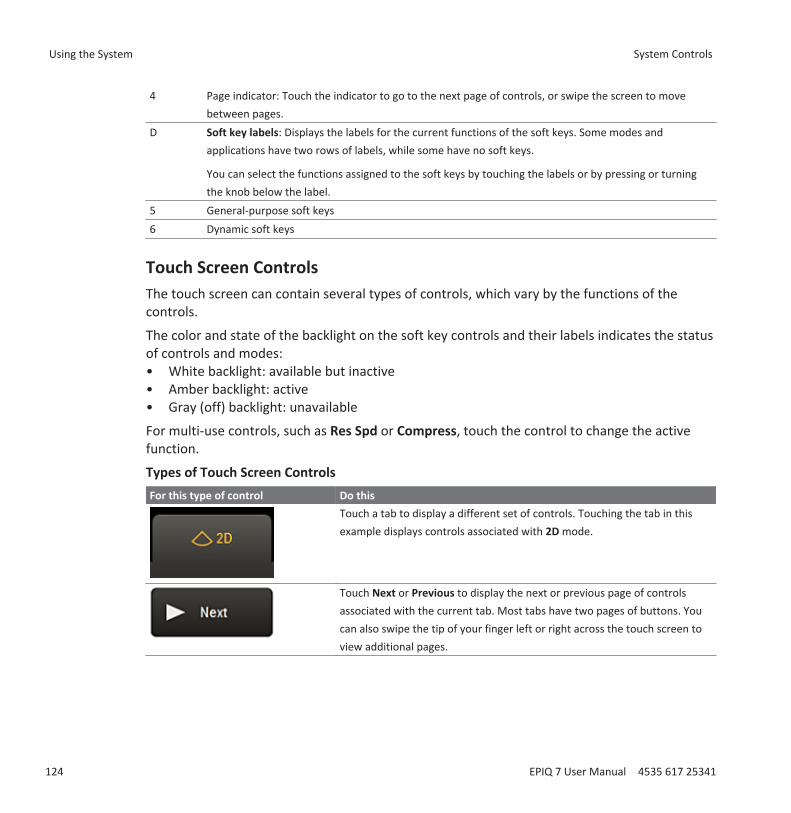
4 Page indicator: Touch the indicator to go to the next page of controls, or swipe the screen to movebetween pages.
D Soft key labels: Displays the labels for the current functions of the soft keys. Some modes andapplications have two rows of labels, while some have no soft keys.
You can select the functions assigned to the soft keys by touching the labels or by pressing or turningthe knob below the label.
5 General-purpose soft keys6 Dynamic soft keys
Touch Screen ControlsThe touch screen can contain several types of controls, which vary by the functions of thecontrols.
The color and state of the backlight on the soft key controls and their labels indicates the statusof controls and modes:• White backlight: available but inactive• Amber backlight: active• Gray (off) backlight: unavailable
For multi-use controls, such as Res Spd or Compress, touch the control to change the activefunction.
Types of Touch Screen ControlsFor this type of control Do this
Touch a tab to display a different set of controls. Touching the tab in thisexample displays controls associated with 2D mode.
Touch Next or Previous to display the next or previous page of controlsassociated with the current tab. Most tabs have two pages of buttons. Youcan also swipe the tip of your finger left or right across the touch screen toview additional pages.
Using the System System Controls
124 EPIQ 7 User Manual 4535 617 25341
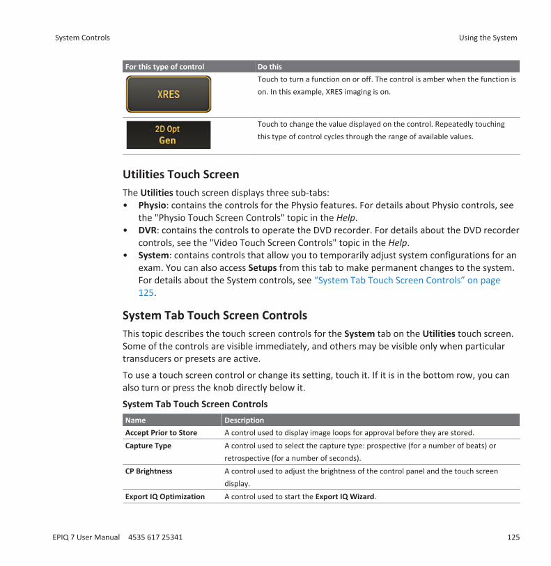
For this type of control Do thisTouch to turn a function on or off. The control is amber when the function ison. In this example, XRES imaging is on.
Touch to change the value displayed on the control. Repeatedly touchingthis type of control cycles through the range of available values.
Utilities Touch ScreenThe Utilities touch screen displays three sub-tabs:• Physio: contains the controls for the Physio features. For details about Physio controls, see
the "Physio Touch Screen Controls" topic in the Help.• DVR: contains the controls to operate the DVD recorder. For details about the DVD recorder
controls, see the "Video Touch Screen Controls" topic in the Help.• System: contains controls that allow you to temporarily adjust system configurations for an
exam. You can also access Setups from this tab to make permanent changes to the system.For details about the System controls, see “System Tab Touch Screen Controls” on page125.
System Tab Touch Screen ControlsThis topic describes the touch screen controls for the System tab on the Utilities touch screen.Some of the controls are visible immediately, and others may be visible only when particulartransducers or presets are active.
To use a touch screen control or change its setting, touch it. If it is in the bottom row, you canalso turn or press the knob directly below it.
System Tab Touch Screen ControlsName DescriptionAccept Prior to Store A control used to display image loops for approval before they are stored.Capture Type A control used to select the capture type: prospective (for a number of beats) or
retrospective (for a number of seconds).CP Brightness A control used to adjust the brightness of the control panel and the touch screen
display.Export IQ Optimization A control used to start the Export IQ Wizard.
System Controls Using the System
EPIQ 7 User Manual 4535 617 25341 125
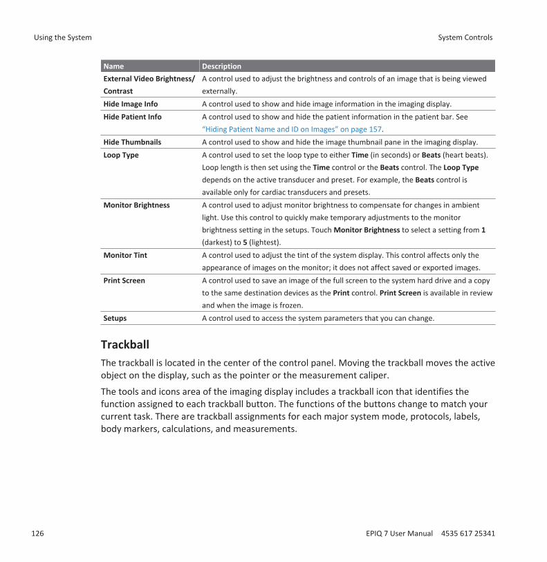
Name DescriptionExternal Video Brightness/Contrast
A control used to adjust the brightness and controls of an image that is being viewedexternally.
Hide Image Info A control used to show and hide image information in the imaging display.Hide Patient Info A control used to show and hide the patient information in the patient bar. See
“Hiding Patient Name and ID on Images” on page 157.Hide Thumbnails A control used to show and hide the image thumbnail pane in the imaging display.Loop Type A control used to set the loop type to either Time (in seconds) or Beats (heart beats).
Loop length is then set using the Time control or the Beats control. The Loop Typedepends on the active transducer and preset. For example, the Beats control isavailable only for cardiac transducers and presets.
Monitor Brightness A control used to adjust monitor brightness to compensate for changes in ambientlight. Use this control to quickly make temporary adjustments to the monitorbrightness setting in the setups. Touch Monitor Brightness to select a setting from 1(darkest) to 5 (lightest).
Monitor Tint A control used to adjust the tint of the system display. This control affects only theappearance of images on the monitor; it does not affect saved or exported images.
Print Screen A control used to save an image of the full screen to the system hard drive and a copyto the same destination devices as the Print control. Print Screen is available in reviewand when the image is frozen.
Setups A control used to access the system parameters that you can change.
TrackballThe trackball is located in the center of the control panel. Moving the trackball moves the activeobject on the display, such as the pointer or the measurement caliper.
The tools and icons area of the imaging display includes a trackball icon that identifies thefunction assigned to each trackball button. The functions of the buttons change to match yourcurrent task. There are trackball assignments for each major system mode, protocols, labels,body markers, calculations, and measurements.
Using the System System Controls
126 EPIQ 7 User Manual 4535 617 25341

Trackball Arbitration Icon
For example, the functions of the left and right trackball buttons can include:• Cycle through cineloop sequences when the image is frozen or in Review.• Erase traces.• Select measurements within a group.
The functions of the middle trackball button include:• Activate the spectral trace in M-mode and Doppler imaging.• Complete measurements and calculations.
The labels under the trackball image indicate the functions that are available for the entiretrackball.
NOTEFor some measurements, the trackball functions become available only after you pressMeasure.
Also, you can configure the left and right trackball buttons by using the Left Select Key andRight Select Key settings in the Tools & Results tab of the Analysis setups.
Soft Key ControlsSoft key controls (knobs that can be pressed and turned) are located along the top of thecontrol panel. Two rows of labels for soft key functions and settings appear along the bottom ofthe touch screen. Each column of labels corresponds to the soft key below it on the controlpanel. The soft keys select imaging features and settings. The functions of the soft keys changedepending on the mode, the application, the preset, and the transducer.
System Controls Using the System
EPIQ 7 User Manual 4535 617 25341 127

If a function is assigned to a soft key, the ring around the knob is amber. If no function isassigned to a soft key, the ring is dark.
Sometimes, two functions are available for a soft key. Only one of the functions can be active ata time. Pressing the corresponding knob on the control panel or touching the label selects theactive function. The label for active functions is amber. The label for inactive functions is white.
Many modes offer two or more pages of soft keys. To display the second page place your fingeron the touch screen and swipe to the left. To return to the first page place your finger on thetouch screen and swipe to the right. You can also touch the page indicator, located above thesoft keys, to display the next available page of soft keys.
Soft Key Page Indicator
Using the KeyboardsThe system has two keyboards, which you can use to enter patient data, exam comments,image annotation, and your logon password.
Touch Screen Keyboard
One keyboard is located on the touch screen. That keyboard may appear automatically duringcertain activities.
To use the touch screen keyboard:
1. If necessary, touch (keyboard) to display the keyboard.2. When you are done typing, touch Close.
Retractable Keyboard
A retractable keyboard is located beneath the control panel.
To use the retractable keyboard:1. Pull out the keyboard. The keyboard lights after you pull it out completely.2. When you are done typing, push in the keyboard in completely.
Using the System System Controls
128 EPIQ 7 User Manual 4535 617 25341
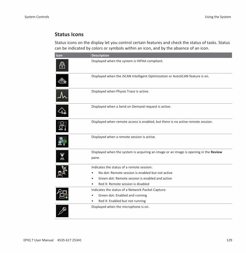
Status IconsStatus icons on the display let you control certain features and check the status of tasks. Statuscan be indicated by colors or symbols within an icon, and by the absence of an icon.Icon Description
Displayed when the system is HIPAA compliant.
Displayed when the iSCAN Intelligent Optimization or AutoSCAN feature is on.
Displayed when Physio Trace is active.
Displayed when a Send on Demand request is active.
Displayed when remote access is enabled, but there is no active remote session.
Displayed when a remote session is active.
Displayed when the system is acquiring an image or an image is opening in the Reviewpane.
Indicates the status of a remote session:• No dot: Remote session is enabled but not active• Green dot: Remote session is enabled and active• Red X: Remote session is disabledIndicates the status of a Network Packet Capture:• Green dot: Enabled and running• Red X: Enabled but not runningDisplayed when the microphone is on.
System Controls Using the System
EPIQ 7 User Manual 4535 617 25341 129
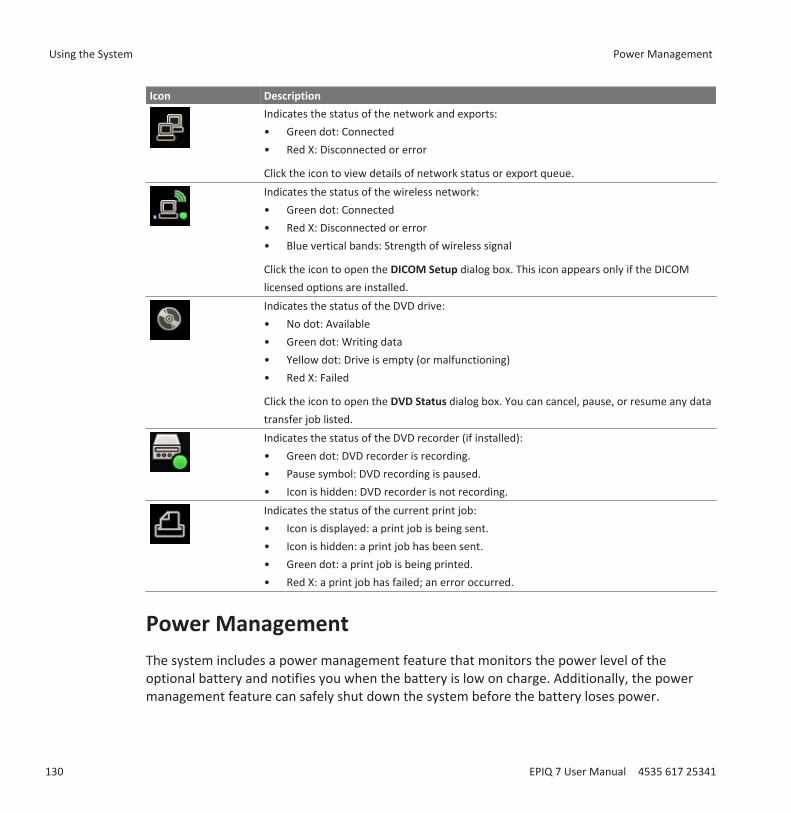
Icon DescriptionIndicates the status of the network and exports:• Green dot: Connected• Red X: Disconnected or error
Click the icon to view details of network status or export queue.Indicates the status of the wireless network:• Green dot: Connected• Red X: Disconnected or error• Blue vertical bands: Strength of wireless signal
Click the icon to open the DICOM Setup dialog box. This icon appears only if the DICOMlicensed options are installed.Indicates the status of the DVD drive: • No dot: Available• Green dot: Writing data• Yellow dot: Drive is empty (or malfunctioning)• Red X: Failed
Click the icon to open the DVD Status dialog box. You can cancel, pause, or resume any datatransfer job listed.Indicates the status of the DVD recorder (if installed):• Green dot: DVD recorder is recording.• Pause symbol: DVD recording is paused.• Icon is hidden: DVD recorder is not recording.Indicates the status of the current print job: • Icon is displayed: a print job is being sent.• Icon is hidden: a print job has been sent.• Green dot: a print job is being printed.• Red X: a print job has failed; an error occurred.
Power ManagementThe system includes a power management feature that monitors the power level of theoptional battery and notifies you when the battery is low on charge. Additionally, the powermanagement feature can safely shut down the system before the battery loses power.
Using the System Power Management
130 EPIQ 7 User Manual 4535 617 25341
The batteries charge whenever the system is connected to AC power.
CAUTIONThe batteries are used to ensure quick system startup and easy movement of the systemonly. You cannot perform scans while in battery mode.
CAUTIONWhen shipping the system, make sure the batteries are inserted upside down to preventelectrical discharge.
NOTEWhen the system is turned on and in Sleep Mode, the batteries power the system.
NOTEWhen the battery-charge level reaches a critically low state, the system shuts downautomatically.
NOTEThe batteries may need to be replaced. For information on replacing the batteries, see thesystem Service Manual.
Sleep ModeSleep Mode uses battery power and allows quick startup of the system. It does not eliminatepower consumption and should be used only for short periods of time, such as when you
transport the system between exam locations. The Sleep Mode control ( ) is in the upper left
corner of the control panel, next to the (On/Off) control. When the system is in Sleep Mode,it freezes live imaging, pauses any open study, exits any QLAB study, and terminates anyremote connection. Awaken the system to resume normal system operation.
Power Management Using the System
EPIQ 7 User Manual 4535 617 25341 131

When the system is on battery power, the Sleep Mode time-out is approximately 20 minutes.The system remains in Sleep Mode until it is awakened or powered off, or until the batteriesdischarge to a critically low state. If the system batteries discharge to a critically low state, thesystem safely shuts down from Sleep Mode.
To put the system in Sleep Mode, press or disconnect the power cord.
To awaken the system, press .
For information on the Sleep Mode status indicators, see “Turning the System On and Off” onpage 113.
NOTEWhen the system is in Sleep Mode and is connected to AC power, the system remains in SleepMode until it is awakened.
Battery IndicatorsThe battery charge level is indicated by icons on the system display.
CAUTIONThe batteries are used to ensure quick system startup and easy movement of the systemonly. You cannot perform scans while in battery mode.
NOTEThe system batteries are a purchasable option. If this option is not purchased, the battery iconis not displayed.
Using the System Power Management
132 EPIQ 7 User Manual 4535 617 25341
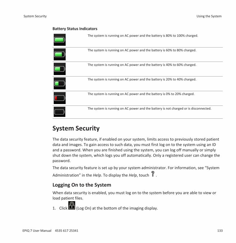
Battery Status IndicatorsThe system is running on AC power and the battery is 80% to 100% charged.
The system is running on AC power and the battery is 60% to 80% charged.
The system is running on AC power and the battery is 40% to 60% charged.
The system is running on AC power and the battery is 20% to 40% charged.
The system is running on AC power and the battery is 0% to 20% charged.
The system is running on AC power and the battery is not charged or is disconnected.
System SecurityThe data security feature, if enabled on your system, limits access to previously stored patientdata and images. To gain access to such data, you must first log on to the system using an IDand a password. When you are finished using the system, you can log off manually or simplyshut down the system, which logs you off automatically. Only a registered user can change thepassword.
The data security feature is set up by your system administrator. For information, see “System
Administration” in the Help. To display the Help, touch .
Logging On to the SystemWhen data security is enabled, you must log on to the system before you are able to view orload patient files.
1. Click (Log On) at the bottom of the imaging display.
System Security Using the System
EPIQ 7 User Manual 4535 617 25341 133
2. In the Logon dialog box, type your user name.3. Press the Tab key and type your password. (If you forget your system password, contact
your system administrator.)4. Click OK to log on to the system and start the valid access period.
NOTELogging off of the system does not change the current patient, but it does deny further accessto protected patient data.
Logging Off of the SystemIf you do not log off, the system automatically logs you off when you shut down the system orafter the system has been inactive for the length of time shown in Auto Log Off on the UserSettings tab of the Data Security setups.
1. Click (Log Off) at the bottom of the imaging display.2. In the LogOff dialog box, click Yes.
Changing Your PasswordIf the data security feature is enabled on your system, you must log on to the system to gainaccess to patient data and images.
Once the system administrator has given you a password for the system, you can change it asneeded. A password must be 6 to 10 characters long and can contain only letters and numbers;punctuation marks and symbols are not allowed.
NOTEThe Auto Log Off time shown on the User Settings display indicates how long the system can beinactive before you are logged off automatically. Only the system administrator can change thissetting.
1. Touch Utilities.
Using the System System Security
134 EPIQ 7 User Manual 4535 617 25341
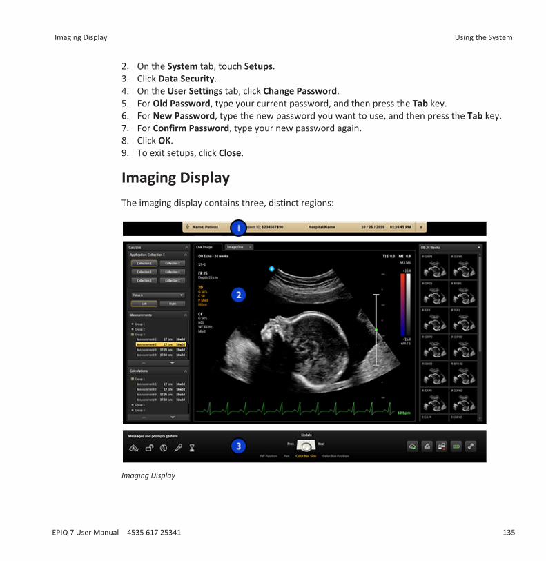
2. On the System tab, touch Setups.3. Click Data Security.4. On the User Settings tab, click Change Password.5. For Old Password, type your current password, and then press the Tab key.6. For New Password, type the new password you want to use, and then press the Tab key.7. For Confirm Password, type your new password again.8. Click OK.9. To exit setups, click Close.
Imaging DisplayThe imaging display contains three, distinct regions:
Imaging Display
Imaging Display Using the System
EPIQ 7 User Manual 4535 617 25341 135
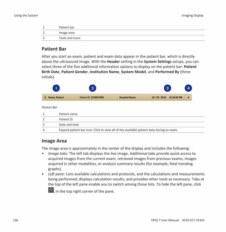
1 Patient bar2 Image area3 Tools and icons
Patient BarAfter you start an exam, patient and exam data appear in the patient bar, which is directlyabove the ultrasound image. With the Header setting in the System Settings setups, you canselect three of the five additional information options to display on the patient bar: PatientBirth Date, Patient Gender, Institution Name, System Model, and Performed By (threeinitials).
Patient Bar
1 Patient name2 Patient ID3 Date and time4 Expand patient bar icon: Click to view all of the available patient data during an exam.
Image AreaThe image area is approximately in the center of the display and includes the following:• Image tabs: The left tab displays the live image. Additional tabs provide quick access to
acquired images from the current exam, retrieved images from previous exams, imagesacquired in other modalities, or analysis summary results (for example, fetal trendinggraphs).
• Left pane: Lists available calculations and protocols, and the calculations and measurementsbeing performed; displays calculation results; and provides other tools as necessary. Tabs atthe top of the left pane enable you to switch among those lists. To hide the left pane, click
, in the top right corner of the pane.
Using the System Imaging Display
136 EPIQ 7 User Manual 4535 617 25341

• Imaging area: Displays the live image (or other applications, such as Q-Apps), a depth scalethat includes the focus setting (to the right of the image), a TGC curve, a grayscale bar, anda color bar (to the right of the depth scale). In M-mode and Doppler, the sweeping displayappears either below the 2D image or to the right of it, depending on the format you select.
• Thumbnail pane: Displays thumbnail images from the current exam.
For general imaging, a scan plane orientation marker appears at the top left of the image.For cardiac exams, the orientation marker appears at the top right of the image. The markercorresponds to the orientation marker on the transducer. The marker always follows theorientation of the image. When you invert the image by using Left/Right or Top/Bottom, themarker position changes accordingly.
Image Area
A Left paneB Imaging area1 Image tabs2 Scan plane orientation marker
Imaging Display Using the System
EPIQ 7 User Manual 4535 617 25341 137
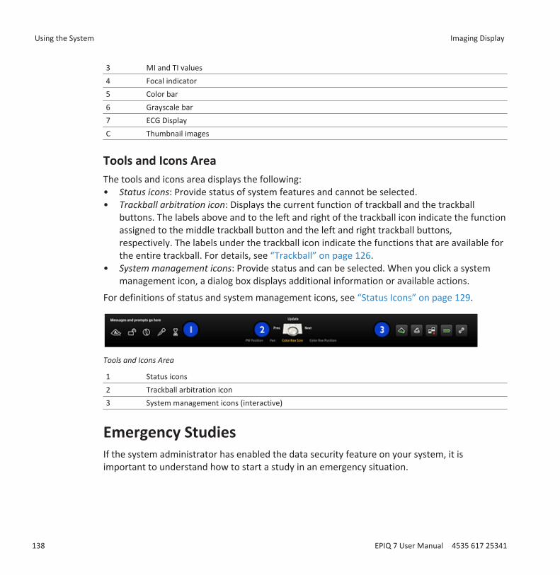
3 MI and TI values4 Focal indicator5 Color bar6 Grayscale bar7 ECG DisplayC Thumbnail images
Tools and Icons AreaThe tools and icons area displays the following:• Status icons: Provide status of system features and cannot be selected.• Trackball arbitration icon: Displays the current function of trackball and the trackball
buttons. The labels above and to the left and right of the trackball icon indicate the functionassigned to the middle trackball button and the left and right trackball buttons,respectively. The labels under the trackball icon indicate the functions that are available forthe entire trackball. For details, see “Trackball” on page 126.
• System management icons: Provide status and can be selected. When you click a systemmanagement icon, a dialog box displays additional information or available actions.
For definitions of status and system management icons, see “Status Icons” on page 129.
Tools and Icons Area
1 Status icons2 Trackball arbitration icon3 System management icons (interactive)
Emergency StudiesIf the system administrator has enabled the data security feature on your system, it isimportant to understand how to start a study in an emergency situation.
Using the System Imaging Display
138 EPIQ 7 User Manual 4535 617 25341
In an emergency, you can start a study without entering patient data. During an emergencystudy, the system provides a temporary ID for image acquisition and report editing. You shouldchange the temporary ID to correct the patient data before you end the study. Otherwise, thetemporary ID is the only identifier for that study.
Temporary IDUse the temporary ID feature to start an exam quickly. This feature allows you to perform anexam without first entering patient data. When you select this feature, the system entersunique, temporary placeholders for the patient's last name and ID. Using the temporary IDfeature allows you to perform an exam as you would normally.
When you use the temporary ID workflow, images can be sent to a PACS or to a DICOM printerbefore entering actual patient data, if the system is configured to send or print images as youscan.
For an exam started with a temporary ID, edit patient data before ending the exam. After theexam is ended, you cannot change patient data. When the patient data is changed, all imagesare automatically resent to any local printers that they were previously sent to. If your system isconnected to a DICOM Worklist Server, you can load patient data to replace the temporary IDdata.
NOTEIf you have configured a DICOM performed-procedure-step-server, PPS messages are sent forthe temporary ID. If you have configured a PPS server, PPS discontinue messages are sent forthe temporary ID if you edit the patient data before you end the exam.
Starting Emergency StudiesIn an emergency, you can use the temporary ID feature to start an exam without first having toenter patient data. Just click Use Temporary ID after you acquire an image.
You can create a temporary ID when starting a protocol, printing, acquiring an image, or savinga volume.1. Touch Patient and then click Use Temporary ID.2. Click Done.
Emergency Studies Using the System
EPIQ 7 User Manual 4535 617 25341 139

3. When the exam is finished, do the following:a. Touch End Exam.b. Edit the information in the Patient Data displayc. Click End Exam.d. Click Done.
Setting the Auto Freeze FunctionThe Auto Freeze function stops imaging and freezes the image, if a control is not manipulatedwithin the Wait time that you specify. The default time is 5 minutes. After Auto Freeze has beeninvoked, press any control to restart imaging.1. Touch Utilities.2. On the System tab, touch Setups.3. Click System Settings.4. Click the Display tab.5. Under Auto Freeze, select On, and then select the Wait time.6. Click Done.
Transducer Receptacles and Cable ManagementThe system includes four receptacles for imaging transducers, one receptacle for a pulsed- orcontinuous-wave Doppler probe, and one receptacle for physio, if physio is included in yoursystem's configuration. All receptacles can be occupied simultaneously, but only one transducerat a time can be active.
Using the System Setting the Auto Freeze Function
140 EPIQ 7 User Manual 4535 617 25341

Transducer Receptacles
1 Physio probe receptacle2 Doppler probe receptacle3 Imaging transducer receptacle
When a transducer is not in use, store it in one of the transducer holders on the system cart.Always loop transducer cables over the cable hangers to prevent cables from being stepped onor run over by the cart wheels.
Transducer Receptacles and Cable Management Using the System
EPIQ 7 User Manual 4535 617 25341 141
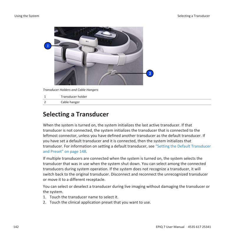
Transducer Holders and Cable Hangers
1 Transducer holder2 Cable hanger
Selecting a TransducerWhen the system is turned on, the system initializes the last active transducer. If thattransducer is not connected, the system initializes the transducer that is connected to theleftmost connector, unless you have defined another transducer as the default transducer. Ifyou have set a default transducer and it is connected, then the system initializes thattransducer. For information on setting a default transducer, see “Setting the Default Transducerand Preset” on page 148.
If multiple transducers are connected when the system is turned on, the system selects thetransducer that was in use when the system shut down. You can select among the connectedtransducers during system operation. If the system does not recognize a transducer, it willswitch back to the original transducer. Disconnect and reconnect the unrecognized transduceror move it to a different receptacle.
You can select or deselect a transducer during live imaging without damaging the transducer orthe system.1. Touch the transducer name to select it.2. Touch the clinical application preset that you want to use.
Using the System Selecting a Transducer
142 EPIQ 7 User Manual 4535 617 25341

After you select the clinical application/preset, the system calibrates the transducer, enablesthe transducer for operation, and updates system status to reflect the transducer type and thepreset you selected.
Selecting a PresetWhen the system is turned on, the system selects the same preset that was in use when thesystem shut down (unless it is incompatible with the initially selected transducer). For moreinformation, see “Setting the Default Transducer and Preset” on page 148.
During system operation, you can select a different preset for the selected transducer.1. Touch the transducer name.2. Touch a preset to select it.
ECG FeatureThe system can display three physio traces, each representing a physiological input. Theseinputs can include low-level ECG, high-level ECG, respiratory, pulse, phono, and auxiliarysignals. (Low-level ECG comes from leads connected to the patient; high-level ECG comes froma patient monitor or other similar equipment.) Heart rate, derived from the ECG signal, isdisplayed on the screen whenever ECG is connected and displayed.
DVD, CD, and USB DevicesThe system supports a variety of removable media including DVD, CD, and USB storage devices.
For additional information on specific applications of the DVD drive, see the Help. To display the
Help, touch . To close the Help, touch Close or touch again.
For details about DVD and CD devices, see “DVD Drive” on page 144.
For details about USB devices, see “USB Devices” on page 145.
Media CompatibilityCD media capacity is approximately 700 MB; single-layer DVD media capacity is approximately4.7 GB. Rewritable media types (indicated by the RW suffix) can be erased and used again, butyou cannot erase media that has the R suffix. Dual-layer DVD media is unsupported.
Selecting a Preset Using the System
EPIQ 7 User Manual 4535 617 25341 143
DVD and CD media are available in a number of types. Not all media types are fully compatiblewith the system DVD drive. To ensure consistent performance, use only high-quality CD or DVDmedia in the system DVD drive. For more information, see Media Compatibility on the UserInformation CD.
For information regarding USB media, see “USB Devices” on page 145.
Multiple studies can be written to a disc, during one upload, up to the limit of its capacity. Afterthe studies are written to the disc, the disc is finalized and cannot be written to again. To reusea finalized RW disc, you must first reformat it. To record multiple studies to a disc, you mustend the exam you just recorded before removing the disc.
NOTEA single disc can be used between different EPIQ 7 systems, but only for writing logs and setupdata.
DVD DriveThe system includes a DVD drive, located on the right side of the control module. You can usethis drive to store and transfer patient files, including full exams, 3D data sets, and reports. Inaddition, you can save, restore, and distribute configuration data.
You do not need to format a disc before storing data on it.
Loading and Ejecting a DiscDo one of the following:
• To load a disc, gently guide a disc into the drive slot, until the disc is pulled into the drive.• To eject a disc, press the Eject button on the drive.
Erasing a DVDErasing a rewritable disc (DVD+RW, DVD-RW, or CD-RW) erases all of the data on it andprepares it for reuse. After a disc is erased, the entire capacity of the disc is once againavailable. You can also erase a write-once disc (DVD+R, DVD-R, or CD-R), but you will not beable to write files to the erased portion of the disc.
Using the System DVD, CD, and USB Devices
144 EPIQ 7 User Manual 4535 617 25341
NOTEIf the system cannot erase the disc, use a computer to erase it. If the computer cannot erasethe disc, it may be damaged.
1. Touch Review.2. Load a disc into the drive and wait for it to become available.3. In the Review Exam display, click Erase.4. In the Erase Disc dialog box, click OK to erase the disc.5. When the dialog box indicates that erasing is complete, click OK.6. Click Close.
USB DevicesThe system provides USB ports that can be used to connect USB storage devices. Such devicesinclude USB memory devices and USB hard disk drives. USB ports are on the front left of thesystem behind the transducer holders and on the rear panel. Read the following informationbefore using USB storage devices.
The system supports the following USB devices:• Single-partition USB flash memory drives• USB flash memory drives that do not use or contain any antivirus or other executable
software• USB hard disk devices that require 500 mA or less per USB port• USB 2.0 compliant devices• USB 3.0 compliant devices
Some portable hard drives do not work when connected to a single USB port on the system.Connect a dual-port USB cable between the drive and two USB ports behind the right panel ofthe system.
WARNINGConnecting externally powered USB hard disk drives to the system involves electrical safetyrisks. If you connect such drives to the system, you must observe the electrical safetywarnings in the “Safety” section. Philips recommends that you use only USB hard disk drivespowered from the USB connector, or use USB flash memory devices.
DVD, CD, and USB Devices Using the System
EPIQ 7 User Manual 4535 617 25341 145
CAUTIONWhen transferring data to or from a USB device, be sure the transfer is complete beforeremoving the USB device. For USB devices that have an indicator, be sure the indicator is nolonger flashing before removing the device.
CAUTIONUltrasound systems may become vulnerable to security breaches when they acceptremovable media. Removable USB storage devices may contain viruses. Philips recommendsthat you use the system to format USB storage devices before working with them.
CAUTIONPhilips does not recommend that you use USB storage devices for long-term storage. Followyour IT department's recommended practices for intended use of USB storage devices. Formore information about security on the ultrasound system, see Shared Roles for System andData Security, included on your User Information CD.
CAUTIONUse only Class-B-compliant USB storage devices with the system. USB devices that are notClass-B compliant may cause RF emissions that exceed Class B limits. See the device'sdocumentation to determine whether it is Class-B compliant.
DICOM ViewerWhen you export patient data in DICOM format and select Include DICOM Viewer, the systemexports a copy of the DICOM viewer along with the patient data. The DICOM viewer lets youview images, play clips, and adjust images. Changes made to the images cannot be saved. TheDICOM viewer lets you view stress echo data by stage or anatomic view. The viewer supportsthe electronic submission requirements of ICAEL (Intersocietal Commission for theAccreditation of Echocardiography Laboratories).
Using the System DVD, CD, and USB Devices
146 EPIQ 7 User Manual 4535 617 25341
Customizing the SystemYou can customize your system to increase efficiency and streamline your workflow. You can dothe following:• Create presets designed specifically for the exams you perform• Change system settings to reflect your needs• Add options to enhance your imaging abilities• Create custom procedures for specific patients, transducers, and presets.
PresetsA preset is a group of settings that optimizes the system for a specific type of exam. Presetsestablish many initial settings, such as gain value, color map, filter, and items on the touchscreen.
When you turn on your system, the default preset is active. Before you begin an exam, be surethat the appropriate preset is active.
You can choose from several default presets. You cannot delete these default presets.However, they provide a starting point from which you can create your own presets. You cancreate and store up to 45 presets per transducer/application combination, depending on thespace available on the touch screen. If you need to create more than 45 presets per transducer,you can save presets to a DVD or USB storage device and restore them when you need to usethem.
The available presets are determined by the selected transducer.
NOTEPresets are available only if you purchased the corresponding application-package option.
6
Presets Customizing the System
EPIQ 7 User Manual 4535 617 25341 147
Setting the Default Transducer and PresetYou can set a default transducer and preset so that each time the system is turned on, thattransducer and preset are initiated automatically. The system selects the default transducerregardless of which receptacle it is connected to. If the default transducer is not connectedwhen the system is turned on, the system initiates the transducer connected to the left-mostconnector and the first available preset for that transducer.1. Touch the name of the transducer you want to use.2. Touch the preset you want.3. Touch the transducer name a second time.4. Touch Set Default.
Clinical Applications and PresetsClinical applications are broad areas of medical study. Within each clinical application, there arePhilips presets for specific areas of study. For example, within the Small Organs clinicalapplication, the presets are Thyroid, Testicle, and Breast. The transducer touch screen lists theavailable clinical application preset combinations for the selected transducer.
You specify how the system will be set up for operation by selecting a clinical applicationpreset.
Quick Save PresetsQuick Save presets provide a quick way to set imaging parameters to the values you prefer for aspecific exam type. Using the Quick Save feature, you can define presets for any combination ofclinical application, preset, and transducer. A Quick Save preset stores the primary imagingmode and settings that are active when you create the Quick Save preset.
Once you create a Quick Save preset, it appears on the transducer touch screen when theassociated transducer is selected. When you select the Quick Save preset, the systemautomatically invokes the settings in the preset. You can delete existing Quick Save presets,copy them onto a DVD or USB storage device, and load them into another EPIQ 7 system.
The number of Quick Save presets you can store for a transducer/application combination islimited only by the number of buttons available on the corresponding transducer touch screen.The number of buttons available, in turn, is dependent on which application is selected andhow many presets that application includes.
Customizing the System Presets
148 EPIQ 7 User Manual 4535 617 25341

Creating Quick Save PresetsYou can create a new Quick Save preset that is based on an existing preset. You can do thiseven during an exam, while using the preset.1. Touch the Transducer name.2. Touch the preset on which you want to base your Quick Save preset.3. Adjust the system controls to create the settings for your preset. (You can select an imaging
mode, an image orientation, the number of focal zones, and so on.)4. Swipe the touch screen, from right to left, to view the second page of the transducer
presets.5. Touch Save Preset.
• For the Quick Save Label, type the name of the new preset. If you do not enter a namebefore saving a preset, the system assigns a name.
• For Calculation Package, select a calculation package.• For Annotation/Body Marks, select the annotation and body mark you want as the
defaults.6. Click OK.
Deleting Quick Save PresetsYou can delete any Quick Save preset on the system except the active preset.1. If a preset you want to delete is active, deactivate it by touching the associated transducer
name and a different preset.2. Swipe the touch screen, from right to left, to view the second page of the transducer
presets.3. Touch Delete User Presets.4. Click OK.
Copying Quick Save Presets to Removable MediaYou can copy Quick Save presets to a DVD or a USB storage device. This function is useful forarchiving presets and for sharing presets among other EPIQ 7 systems. When you copy QuickSave presets, all available data is copied.
Presets Customizing the System
EPIQ 7 User Manual 4535 617 25341 149
NOTEIf you receive an error message when exporting data to a DVD or when viewing exam data on aDVD, you may need to eject the DVD from the drive and re-insert it.
1. Load a DVD into the DVD drive, or connect a USB device to a USB port on the system.2. On the control panel, press Support.3. Click System Management.4. Click Backup/Restore.5. From the Select the Media menu, select the removable media that you are using.6. Click Backup. The backup list shows the data that is backed up.7. If a dialog box indicates that the media is too full to complete the copy process, replace the
media and click Backup again.8. After the backup is complete, click Close.9. Click Done.
Loading Quick Save Presets from Removable Media1. Load the DVD containing the data into the DVD drive, or connect the USB device containing
the data to a USB port on the system.2. On the control panel, press Support.3. Click System Management.4. Click Backup/Restore.5. From the Select the Media menu, select the media type that you are using.6. Deselect the data that you do not want to import.7. After the import is complete, click OK.8. To close the Philips SupportConnect display, click Close. A displayed message might prompt
you to restart the system.
System SetupsSetups are system parameters that you can change. By changing setups, you can customize thesystem to meet your operating preferences.
Customizing the System Presets
150 EPIQ 7 User Manual 4535 617 25341
Setups are organized into five standard categories: System Settings, Analysis, Annotation,Acquisition/Capture, and Data Security. An additional category, Setup Wizard, helps youquickly prepare your system for use. Changes in setups take effect immediately and remain ineffect until you change them again or load setups from a DVD or USB device.
NOTEThe institution name exported with DICOM data always reflects the name shown in the setupsat the time the study ended. Philips recommends restarting the system after changingInstitution Name in the setups.
Procedures for using setup options and descriptions of settings are included throughout theHelp.
Changing Setups1. Touch Utilities.2. On the System tab, touch Setups.3. Click a setup category on the left side of the setups display.4. Click a tab or sub-tab at the top of the setups display.5. Enter text or make selections necessary to set up your system.6. Click Close.
Hiding the Doppler Velocity Minus SignYou can choose to include only the numeric value of the Doppler velocity measurements.Doppler velocity is marked as negative (-) when the flow is moving away from the transducer.When reporting on the measurements, you may want only the value, not the direction of flow.When hidden, the negative sign does not appear on the displayed or printed patient reports;however, the sign is still part of the number and is visible when editing a patient report and isincluded in DICOM structured reports exported from the system.
The option to hide the Doppler velocity minus sign is available in all calculation packages exceptAdult Echo and Pediatric Echo.
System Setups Customizing the System
EPIQ 7 User Manual 4535 617 25341 151
NOTEWhen Hide Doppler Velocity Minus Sign is enabled, avoid using the Doppler velocity valuedisplayed in the results and report for manual calculations. The sign value, whether visible ornot, affects any calculations performed with the reported value. The system includes the signvalue in calculations.
To specify the display of the Doppler velocity minus sign:1. Touch Utilities.2. In the System tab, touch Setups.3. Click Analysis.4. Select the tab of the calculations package that you want to change, and then click Tools &
Results.5. Under Hide Doppler Velocity Minus Sign, select On or Off.6. Click Close.
System OptionsIn addition to the standard features available in the system, other features are available aspurchasable licensed options. The types of options available include clinical applications,protocols, imaging capabilities, QLAB Advanced Quantification Software Q-Apps, PercuNavImage Fusion and Interventional Navigation, and connectivity capabilities.
To add licensed options to your system, you purchase them from your Philips representative.Once purchased, they are installed in your system by a Philips field service engineer.
Custom ProceduresYou can automate a variety of workflows by creating custom procedures for specific patients,transducers, and presets.
Creating a Custom Procedure1. Touch Utilities.2. On the System tab, touch Setups.3. Click System Settings.4. Click the Patient Data tab.
Customizing the System System Options
152 EPIQ 7 User Manual 4535 617 25341
5. Under Procedure Setup, do one of the following:• To create a new procedure, click Create New.• To modify an existing procedure or create a new procedure from an existing
procedure, select an item from the Procedure list, and then click Modify.• To delete an existing procedure, select an item from the Procedure list, and then click
Delete.6. For new or modified procedures, complete the following:
• Procedure Name: Enter the name of a new procedure, or modify the name of anexisting procedure.
• Study Description: Enter the type of study for which the new or modified procedure isintended.
• Gender: Select the gender of the patient.• Study Description: Enter a brief, meaningful description of the study in which the new
or modified procedure is used.• Transducer: Select a transducer from a list of all of the transducers that are supported
by the system.• Preset: Select a preset from a list of all of the presets that are available for the
selected transducer.7. Click Save and then click Close.
To use the new custom procedure, see “Selecting a Custom Procedure” on page 153.
Selecting a Custom ProcedureCustom procedures are available from the Patient Data form.
NOTECustom procedures are linked to specific transducers. If the transducer required for theprocedure is unconnected, procedures that use it do not appear in the Procedure menu.
1. Touch Patient.2. In the Clinical Procedure section of the Patient Data form, select the custom procedure
from the Procedure menu.3. Click Done.4. Start the exam.
Custom Procedures Customizing the System
EPIQ 7 User Manual 4535 617 25341 153

Customizing the System Custom Procedures
154 EPIQ 7 User Manual 4535 617 25341
Performing an ExamThis section guides you through procedures commonly used in performing patient exams withthe system. These procedures include entering patient data; acquiring, annotating, andreviewing images; and making measurements and calculations.
New Patient Exams
WARNINGFailing to end the current exam before starting a new exam can result in data being acquiredand stored under the wrong patient name.
You start an exam by entering patient data into the system. There are two ways to enterpatient data.• If the Modality Worklist feature is disabled or unused on your system, you enter patient
data into the Patient Data form.• If your system is connected to a DICOM network with the Modality Worklist feature
enabled, you can select an exam to load patient data instead of entering that informationmanually. See “Selecting in the Worklist” on page 156.
If you want to start an exam without first entering patient data, you can select Use TemporaryID after you acquire an image.
The system uses a unique ID to identify each patient. You can enter an ID, or you can have thesystem create one automatically. Stored images, fetal growth graphs, and reports are storedbased on the patient ID.
If the sonographer name needs to be different on images within the exam, end the currentexam and append a new exam with the images from the new sonographer.
An accession number is an optional entry assigned to each patient file by an institution forinternal information-management purposes.
The exam date is set by the system when you first acquire an image during the exam.
7
New Patient Exams Performing an Exam
EPIQ 7 User Manual 4535 617 25341 155
Entering Patient DataIf you are not using the worklist option, you start an exam by entering patient data into thesystem.
If you want to start an exam without first entering patient data, you can select Use TemporaryID after you acquire an image.
NOTEYou can clear all patient data from the Patient Data form by clicking Clear. Do not use thiscontrol unless you want to delete all of the patient data you have entered into the form.
1. Touch Patient.2. Ensure that the previous exam ended by doing one of the following:
• Touch End Exam while the Patient Data form is displayed.• Click End Exam on the Patient Data form.
3. On the Patient Data form, type the patient information. (Press the Tab key to move thecursor from field to field.)
4. For Study Type, select the study you will be performing. It is important to select the correctstudy type at this time. Selecting a study type after you have entered patient data andexited the Patient Data form does not update the report with the correct study type.
5. Enter the pertinent study information for the patient.6. If you have created a custom procedure for this patient, select the custom procedure from
the Procedure menu. (For information about custom procedures, see “Custom Procedures”on page 152.)
7. When you are finished, click Done.
Selecting in the Worklist1. Touch Patient.2. On the Patient Data form, click the Worklist tab.3. On the worklist, select the exam you want, and click Close.
The system loads the patient information, and you are ready to begin an exam for thatpatient.
Performing an Exam New Patient Exams
156 EPIQ 7 User Manual 4535 617 25341
Searching in the WorklistIf necessary, you can search for a specific exam by using Patient Search on the Patient Dataform.1. Touch Patient, then click the Worklist tab.2. To search for a patient by exam date, click Search.3. To further specify the date criteria, do one of the following:
• Select the Exam Date.• Select Today; select ± (plus or minus), +, or –; and then select the number of days.
NOTEYou can also search for a patient by last name, patient ID, modality, accession number, orprocedure ID.
4. Click Search.5. Select the patient from the worklist.6. Click Done.
Hiding Patient Name and ID on Images
WARNINGImages printed without the patient name and ID could be incorrectly associated with anotherpatient. One way to alleviate this risk is to configure the DICOM printer so that the patientdata that is included in the header of the image file is printed along with the image. However,some printers do not support that feature.
NOTEIf the intent of hiding the patient name and ID is patient privacy, be aware that if the originalfile name includes the patient name, you will need to rename the file when you export it.
New Patient Exams Performing an Exam
EPIQ 7 User Manual 4535 617 25341 157
The patient name and ID are displayed in the patient bar, which is outside of the image areaand not acquired in an image. However, patient information is overlaid on to an image when itis printed. To hide the patient name and ID on the printed image, touch Utilities, and thentouch Hide Patient Info on the System tab. All other information displayed in the patient bar(time/date, institution name, and so on) remains in the overlay and is included on the printedimage.
Any loop or still frame acquired while the patient name is hidden will also be exported with thepatient name hidden.
Imaging ModesYour ultrasound system offers a set of imaging modes to accommodate a variety of imagingapplications. Some modes display a live grayscale image. Others are Doppler modes to evaluatethe amplitude or the direction of the blood flow and the spectral information. Special modesare also available for 3D imaging and Panoramic imaging.
NOTESome modes are available on your system only if the corresponding option has been purchasedand installed.
Selecting a TransducerWhen the system is turned on, the system initializes the last active transducer. If thattransducer is not connected, the system initializes the transducer that is connected to theleftmost connector, unless you have defined another transducer as the default transducer. Ifyou have set a default transducer and it is connected, then the system initializes thattransducer. For information on setting a default transducer, see “Setting the Default Transducerand Preset” on page 148.
Performing an Exam Imaging Modes
158 EPIQ 7 User Manual 4535 617 25341
If multiple transducers are connected when the system is turned on, the system selects thetransducer that was in use when the system shut down. You can select among the connectedtransducers during system operation. If the system does not recognize a transducer, it willswitch back to the original transducer. Disconnect and reconnect the unrecognized transduceror move it to a different receptacle.
You can select or deselect a transducer during live imaging without damaging the transducer orthe system.1. Touch the transducer name to select it.2. Touch the clinical application preset that you want to use.
After you select the clinical application/preset, the system calibrates the transducer, enablesthe transducer for operation, and updates system status to reflect the transducer type and thepreset you selected.
AnnotationYou can place text labels and arrows on an image to identify anatomical structures andlocations. You can also annotate an image with a body marker graphic that indicates the part ofthe anatomy that you are scanning.
Trackball Functionality in Annotation
Use the touch screen to select annotation labels and body markers, and use the trackball toposition them on the imaging display. The trackball icon identifies the function available foreach trackball button as you add labels and body markers. When adding body markers thefollowing functionality is available:• Left or right trackball button: Highlight and move body marker and the transducer icon.• Middle trackball button: Set the position of the body marker and exit annotation mode. (To
reenter annotation mode, touch the Label tab.)
Adding Labels1. Press ABC Label.
Annotation Performing an Exam
EPIQ 7 User Manual 4535 617 25341 159

NOTEIf you press a trackball button, unfreeze the image, or change the imaging mode or settings thataffect the trackball assignment, annotation mode goes into standby. To return to annotation,press ABC Label.
2. Touch ABC Labels.3. Use the trackball to position the text cursor on the display, or touch Home to return it to
the home location.
NOTEYou cannot move a label once you have added it to the display.
4. Do any of the following:• To add text, type the text that you want to appear on the display.• To display predefined labels, touch a label control to display its text.• To display an arrow, press the Arrow soft key, position the arrow with the trackball,
and then click to fix the position.• To erase an arrow, touch Erase Last.• To erase the last word typed, touch Erase Last to erase all arrows and then erase
words one at a time.• To erase all text, touch Erase All.• To move the text cursor to the home position, touch Home.• To set a new home position, position the cursor and touch Set Home.• To exit annotation mode, press ABC Label again.• To use text replace, see Changing Labels Using Text Replace in the online help.
NOTEErase Last erases all arrows from the image display before it erases text labels.
Performing an Exam Annotation
160 EPIQ 7 User Manual 4535 617 25341
Adding Labels Using the KeyboardYou can add labels using either the retractable keyboard or the touch screen keyboard. You canmanually format the annotation labels that you add using either keyboard.1. Press ABC Label.2. Press the space bar on the keyboard.3. Use the trackball to position the text cursor on the display.4. Type the text that you want to add. You can use spaces before and after the words to
center the text or improve the text flow.5. To erase text, press the Backspace key.6. When finished, press ABC Label again to remove the text cursor.7. To remove text, press ABC Label and then touch Erase Last Word or Erase All Text.
Adding an Image TitleYou can add a title to the image display.1. Press ABC Label.2. Touch ABC Labels.3. Touch Keyboard.4. Touch Title on the keyboard touch screen.5. Type the text that you want to add for the title.6. To erase text, touch Backspace.7. When finished, touch Title again.
Displaying Body Markers
NOTEDuring Review, the Body Markers touch screen is available only when 1‑up is selected forLayout. You cannot add body markers and system-provided labels to single frame images inReview, although you can add them to loops in Review. You can type text in single frameimages in Review.
1. Press ABC Label.
Annotation Performing an Exam
EPIQ 7 User Manual 4535 617 25341 161
2. Touch Body Markers on the ABC Label touch screen to display the Body Markers touchscreen for the current transducer and preset.
3. Touch a body marker control to put the corresponding body marker on the display in thehome location or to replace an existing body marker.
4. Use the trackball to position the transducer scan plane indicator on the body marker. TurnProbe Rotate to change the orientation of the transducer scan plane indicator.
5. Do any of the following:• To move the marker, exit and reenter the Body Markers touch screen, or exit and
reenter annotations mode. When you reenter the Body Markers touch screen you canedit the marker.
• To remove a body marker, touch Erase Body Mark.• To close the Body Markers touch screen, touch another tab title or press ABC Label.
RecordingYou can record live imaging to a local DVD recorder and simultaneously record comments. Youcan play back recordings on other DVD players. Playback is not supported on the system.
Using the DVD Recorder
NOTEUse only DVD+RW media in the DVD recorder.
NOTEAlways format a new disc before using it with the DVD recorder. Also, Philips recommendsreformatting a used disc before using it with the DVD recorder.
1. To turn on the DVD recorder, press on the front panel.2. To insert a disc, press OPEN/CLOSE (on the recorder front panel), place a disc in the tray,
and press OPEN/CLOSE again.3. To record, touch DVR on the touch screen and use any of the following controls on either
the DVR touch screen or the DVD recorder:• (Play) to play back the video at normal speed
Performing an Exam Recording
162 EPIQ 7 User Manual 4535 617 25341
• (Stop) to stop the recording
• (Record) to start recording
• (Pause) to temporarily halt the recording
• (Eject) to stop the current recording mode and eject the media
PrintingYou can print single-frame images and reports to a local printer, usually installed in the system,or to DICOM printers on a network.
WARNINGMulti-image prints made on small-size paper are intended only for reference and should notbe used for diagnostic purposes. Text annotation and scaling markers may not be visible onsuch prints.
Two print controls are available for printing images, Print and Alt Print. The Acquire 1, Acquire2, Acquire Screen, and Acquire Report controls also have print capabilities associated withthem. In the setups, you can assign each of these controls separately to one or more imageprinters. In addition, you can select whether the controls print the entire display or just theimage area.
NOTEIf you print a monochrome image while a Chroma map is selected, the system sends the imageto the color printer. Also, if you export a monochrome image while a Chroma map is selected,the system sends the image as a color image. This is normal. To ensure that black-and-whiteimages are sent to the black-and-white printer, set Chroma to Off.
Printing in Live ImagingYou can print live or frozen images during an exam. To print using the Acquire 1 or Acquire 2controls, a printer must be assigned to those controls in the setups.
Printing Performing an Exam
EPIQ 7 User Manual 4535 617 25341 163
1. Display the live or frozen image you want to print.2. Do one of the following:
• Press Acquire 1 or Acquire 2 on the system control panel.• Touch Alt Print on the touch screen.• Touch Print Screen on the Utilities tab.
NOTEIf your print setting includes multiple images per page, the printer will not print an image untilthe total number is reached. For example, if you have a 2x2 format selected, the printer will notprint the page until you have captured four images or, if the number captured is less than four,until the end of the exam.
ReviewDuring or after an exam, you can use Review to examine and compare images acquired in theexam. You can also review multiple exams for one patient.
In Review, you can look at the images or cineloop sequences that you stored. You can view,send, print, and back up your stored images. You can also perform analysis on images inReview. Images that are in image memory can be stored on the ultrasound system hard drive,on removable media, or on DICOM‑compatible devices on a network. You can display imageswithin an exam in several layouts, and you can display images from different exams.
Starting Review1. Touch Review to enter Review mode. You can also double-click a thumbnail image to open
that image in thumbnail review. The display that appears depends on whether an exam isactive on the system.
NOTEIf an exam is in progress, pressing Review opens the Image Review display. If no exam is inprogress, pressing Review opens the Patient Directory display.
Performing an Exam Review
164 EPIQ 7 User Manual 4535 617 25341
2. To return to live imaging, touch Review again.
Navigating Thumbnails and ImagesIn Review, you can view small images, called thumbnails. Thumbnails are located on the rightside of the Review Exam display. From these thumbnails, you can also display one or moreimages in their original format. If an image represents a 3D data set, it opens in 3D reviewmode.
NOTEWhen reviewing images of an exam loaded from the Patient Directory, thumbnails areunavailable in some circumstances. For example, exams copied from DVD to the hard drive maynot have thumbnails, if the images they contain are no longer in their native format.
Do any of the following:
• Click or to move up or down through available thumbnails one or two images at atime.
• Click a thumbnail to jump to the page that contains the corresponding image.• To view a thumbnail full screen, double-click it. (If the image represents a 3D data set, it
opens in 3D review mode.) To return to the review screen, double-click the full screenimage or set Layout to 4-up.
• Drag the scroll bar to move up or down through available thumbnails quickly.• Turn Page to move backward or forward through the available images, one page at a time.• To select an image, either click the image or click the number of its corresponding
thumbnail.
Capturing Images and LoopsYou can capture and save a single frame or a cineloop sequence. The captured frame orcineloop sequence is saved in the patient study, and a thumbnail of it is available in the liveimaging display and the Review display. Images are automatically exported across the network,
Review Performing an Exam
EPIQ 7 User Manual 4535 617 25341 165

either when you capture or print an image, or when you end an exam, depending on yourselection for Send Images/Clips on the Acquisition/Capture tab in the Acquisition/Capturesetups.
Use the Freeze control to stop and start system image acquisition and update. Pressing Freezeresults in the system entering cineloop pause and assigning the trackball to manual cineloopreview (frame-by-frame).
During acquisition, a spinning hourglass icon appears at the bottom of the display. When thecapture is complete, a thumbnail of the image is displayed.Do one of the following:
• To capture a single image, press Freeze, and then press Acquire 1 or Acquire 2.• To capture a cineloop sequence, press Acquire 1 or Acquire 2 in live imaging or while
reviewing a cineloop sequence. Capturing during live imaging saves prospective orretrospective frames, as specified in Live Capture Type in the setups. A prospective capturecaptures a specified acquired loop length. A retrospective capture captures a specified looplength that was acquired previously. A retrospective capture captures a loop that endswhen you press Acquire 1 or Acquire 2. Capturing while reviewing a cineloop sequencesaves all retrospective frames in the cineloop sequence.You can configure the Acquire 1, Acquire 2, and touch screen print controls in theAcquisition/Capture setups. The default setting is for Acquire 1 to capture single frameswhen the image is frozen and to capture loops when the image is live. Acquire 2 capturessingle frames, regardless of the imaging state. If an Acquire control is set to acquire a stillframe, you can use it to acquire the frame without freezing the image.
NOTEWhen an image is captured, you will hear a beep to confirm that the loop or image was saved inthe patient's study. Do not press Review until you hear the beep.
NOTEIf you press Acquire 1 in a non-simultaneous mode while a live M-mode or Doppler trace isactive, you capture a cineloop sequence. If you press Acquire 1 in a simultaneous mode, youcapture a single image.
Performing an Exam Capturing Images and Loops
166 EPIQ 7 User Manual 4535 617 25341
NOTEIf you attempt to capture a loop that was imported from media, only a frame of the loop iscaptured and displayed in the appending exam.
Measurement and AnalysisThe measurement tools appear on the touch screen. Touching a tool label on the touch screenlaunches the tool. (The labels of inactive tools are gray.)
A calculations package contains one or more collections that organize groups, measurements,and calculations into a coherent tool for diagnostic analysis.
Measurement tools provide measurements and derived calculations. Various methods areavailable for generating results. The two primary methods allow you to “measure then label” or“label then measure.” Either way, the results can appear on the display, on printed pages, andin patient reports, where they are available for your analysis.
The Analysis setups provide the configuration capability that allows you to create your own calclists, including collections, groups, measurements, and calculations. In addition, themeasurements and calculations can be associated with system and custom tables andequations.
The ultrasound system supports a number of measurement and quantification methods. Thebasic measurements report the size, speed, or duration of image data. The image data may becontained in a 2D ultrasound image, a Physio region, an M-mode trace, or a Doppler spectraltrace. The accuracy of the measurement depends, in part, on the ability of the operator.
Measurements are available if the image scaling data is available. This prevents measurementson Doppler or M-mode still images in Review that do not include scaling information in thetrace data, or on imported image loops that use different scaling parameters.
Measurements must be labeled for the results to appear in patient reports. Unlabeledmeasurements appear in the results but are not retained, unless they are associated with alabeled measurement.
Measurement and Analysis Performing an Exam
EPIQ 7 User Manual 4535 617 25341 167
Labeled measurements and calculations are stored in the patient data and report. Theinformation is labeled according to the measurement or calculation label. Within the report,the information is organized by the calculations package. The values displayed can be theresults of multiple measurements.
Calculations packages are system options that are associated with transducers and presets. Acalculations package contains one or more collections that organize measurements andcalculations into a coherent tool for diagnostic analysis. The Calc Package tab provides accessto the various measurements and calculations in the available calculations packages.
The measurements and their derived calculations included with the calculations packages arebased on medical references. See the "References" section in the Help.
NOTEEnsure that you follow current medical practices when identifying specific measurement pointson an image.
Performing a 2D Distance MeasurementA 2D distance measurement uses two calipers to measure the length of a straight line betweenthe two points. You can set the display of the line in the setups.
NOTEThe left and right trackball buttons can each be set to one of three measurement operations:End Measurement, Toggle, or Next Measurement.
1. Obtain the 2D image you want to measure and press Freeze.2. Press or touch Measure.3. Press or touch Measure, and then touch Tools.4. Touch Distance.5. Use the trackball to position the caliper for the first end point and click to anchor it.6. Use the trackball to position the caliper for the second end point. The results update as the
distance between the calipers changes.
Performing an Exam Measurement and Analysis
168 EPIQ 7 User Manual 4535 617 25341
7. To end the measurement, press the middle trackball button.
Measuring M-Mode Distance1. Start M-mode by pressing the M-mode soft key, and then press the middle trackball button
to update the M-mode display.2. Obtain the desired M-mode display and press Freeze.3. Press or touch Measure, and then touch Tools.4. Touch Distance.5. Use the trackball to position the vertical time caliper and press the left or right trackball
button.6. Use the trackball to position the horizontal depth caliper. The distance between the depth
calipers appears in the results.7. To make additional measurements, repeat step 5 and step 6.8. Press the middle trackball button to complete the measurement.
Measuring the Doppler Trace on a Sweeping DisplayThe measurements that appear depend on the settings for Doppler in the Tools and Resultssetups.
You can measure Doppler velocity on a live image.1. Press PW.2. Press the middle trackball button to update the Doppler display.3. Obtain the Doppler image you want to measure (spectral waveform).4. Touch Measure.5. Use the trackball to position the horizontal cursor.6. There are no measurement values in the results; you can read the velocity or frequency
value from the velocity or frequency scale.
Obtaining a Typical Labeled MeasurementThis general procedure describes how to measure by using a typical labeled measurement tool.1. Obtain the image you want to measure and press Freeze.2. Press or touch Measure.3. Do one or more of the following:
• On the Calc Package tab of the touch screen, touch a collection and then ameasurement label.
Measurement and Analysis Performing an Exam
EPIQ 7 User Manual 4535 617 25341 169
• In the Calc List, click a collection and then click a measurement label.4. If a set of associated measurements are required, touch or click a group label to display
multiple measurement labels.5. Touch or click a measurement label and make the measurement. First, the caliper or trace
tool appears on the display. Then, as you make the measurement, the results and derivedcalculations appear in the results and are simultaneously added to the patient report.
6. For each measurement label within a group, touch or click a label and make themeasurement.
7. Press the middle trackball button to complete the measurement.
NOTEThe measurement automatically completes if you unfreeze the image, change modes, or entera report.
Measuring Then LabelingThe measure-then-label method of obtaining results uses caliper controls for makingmeasurements, without first having to select measurement labels. These measurements arenot explicitly associated with a report region and do not appear in the report unless associatedwith a measurement. You can assign these measurements to labels on an as-needed basis.
After making a measurement, you can choose whether to assign the value to a label.
NOTEThe measurement will be lost if you unfreeze the image or change modes before you assign alabel to it.
Ending an ExamEach time you finish an exam, you must end the exam to save images, reports, and other examdata. You can end an exam in the current exam display or with the current exam open in theReview display. You cannot end a paused exam while in the Patient Directory.
Performing an Exam Measurement and Analysis
170 EPIQ 7 User Manual 4535 617 25341
You will not be able to end the exam until the system has saved exam data for the currentexam. (The system saves exam data when you acquire an image.) Ending an exam stores allexam data, clears the Patient Data form, and prepares for the next exam.
WARNINGFailing to end the current exam before starting a new exam can result in data being acquiredand stored under the wrong patient name. If you turn off the system without ending theexam, the system pauses the exam before shutting down.
When the exam is complete, do one of the following:
• Touch End Exam.• Click End Exam in the Patient Data display.
Ending an Exam Performing an Exam
EPIQ 7 User Manual 4535 617 25341 171

Performing an Exam Ending an Exam
172 EPIQ 7 User Manual 4535 617 25341
TransducersThe transducer that you select is the most important factor in image quality. Optimal imagingcannot be obtained without the correct transducer. The system is optimized for use based onyour transducer selection.
The system limits patient contact temperature to 43 degrees Celsius, and acoustic outputvalues to their respective U.S. Food and Drug Administration limits. A power-protection circuitprotects against over-current conditions. If the power monitor protection circuit senses anover-current condition, then the drive voltage to the transducer is shut off immediately,preventing overheating of the transducer surface and limiting acoustic output. Validation of thepower protection circuit is done under normal system operation.
Non-TEE transducers are rated minimum IPX7 in accordance with IEC 60529. Transesophagealtransducers are rated minimum IPX1 (control area) and IPX7 (endoscope area) in accordancewith IEC 60529.
WARNINGAll TEE transducers are designed to be defibrillator safe in accordance with IEC 60601-1.Nevertheless, always remove the transducer from the patient before defibrillation.
WARNINGTo limit potential harm when scanning neonatal, pediatric, and medicated patients, minimizethe time spent imaging at temperatures above 41°C (106°F).
Selecting a TransducerWhen the system is turned on, the system initializes the last active transducer. If thattransducer is not connected, the system initializes the transducer that is connected to theleftmost connector, unless you have defined another transducer as the default transducer. If
8
Selecting a Transducer Transducers
EPIQ 7 User Manual 4535 617 25341 173
you have set a default transducer and it is connected, then the system initializes thattransducer. For information on setting a default transducer, see “Setting the Default Transducerand Preset” on page 174.
If multiple transducers are connected when the system is turned on, the system selects thetransducer that was in use when the system shut down. You can select among the connectedtransducers during system operation. If the system does not recognize a transducer, it willswitch back to the original transducer. Disconnect and reconnect the unrecognized transduceror move it to a different receptacle.
You can select or deselect a transducer during live imaging without damaging the transducer orthe system.1. Touch the transducer name to select it.2. Touch the clinical application preset that you want to use.
After you select the clinical application/preset, the system calibrates the transducer, enablesthe transducer for operation, and updates system status to reflect the transducer type and thepreset you selected.
Setting the Default Transducer and PresetYou can set a default transducer and preset so that each time the system is turned on, thattransducer and preset are initiated automatically. The system selects the default transducerregardless of which receptacle it is connected to. If the default transducer is not connectedwhen the system is turned on, the system initiates the transducer connected to the left-mostconnector and the first available preset for that transducer.1. Touch the name of the transducer you want to use.2. Touch the preset you want.3. Touch the transducer name a second time.4. Touch Set Default.
Clinical Applications and TransducersA clinical application, available for one or more transducers, optimizes the system for a specificapplication.
The clinical applications for each transducer available for the system are listed here.
The following table lists the transducers that are compatible with your ultrasound system.
Transducers Setting the Default Transducer and Preset
174 EPIQ 7 User Manual 4535 617 25341
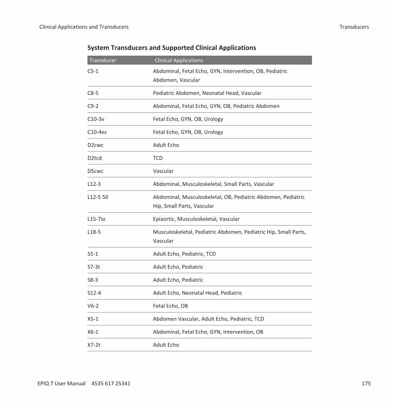
System Transducers and Supported Clinical Applications
Transducer Clinical Applications
C5-1 Abdominal, Fetal Echo, GYN, Intervention, OB, PediatricAbdomen, Vascular
C8-5 Pediatric Abdomen, Neonatal Head, Vascular
C9-2 Abdominal, Fetal Echo, GYN, OB, Pediatric Abdomen
C10-3v Fetal Echo, GYN, OB, Urology
C10-4ec Fetal Echo, GYN, OB, Urology
D2cwc Adult Echo
D2tcd TCD
D5cwc Vascular
L12-3 Abdominal, Musculoskeletal, Small Parts, Vascular
L12-5 50 Abdominal, Musculoskeletal, OB, Pediatric Abdomen, PediatricHip, Small Parts, Vascular
L15-7io Epiaortic, Musculoskeletal, Vascular
L18-5 Musculoskeletal, Pediatric Abdomen, Pediatric Hip, Small Parts,Vascular
S5-1 Adult Echo, Pediatric, TCD
S7-3t Adult Echo, Pediatric
S8-3 Adult Echo, Pediatric
S12-4 Adult Echo, Neonatal Head, Pediatric
V6-2 Fetal Echo, OB
X5-1 Abdomen Vascular, Adult Echo, Pediatric, TCD
X6-1 Abdominal, Fetal Echo, GYN, Intervention, OB
X7-2t Adult Echo
Clinical Applications and Transducers Transducers
EPIQ 7 User Manual 4535 617 25341 175
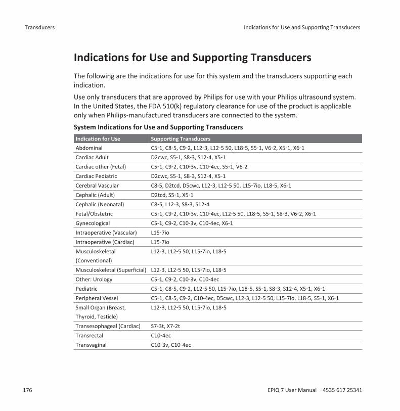
Indications for Use and Supporting TransducersThe following are the indications for use for this system and the transducers supporting eachindication.
Use only transducers that are approved by Philips for use with your Philips ultrasound system.In the United States, the FDA 510(k) regulatory clearance for use of the product is applicableonly when Philips-manufactured transducers are connected to the system.
System Indications for Use and Supporting TransducersIndication for Use Supporting TransducersAbdominal C5‑1, C8‑5, C9‑2, L12‑3, L12‑5 50, L18‑5, S5‑1, V6‑2, X5‑1, X6‑1Cardiac Adult D2cwc, S5‑1, S8‑3, S12‑4, X5‑1Cardiac other (Fetal) C5‑1, C9‑2, C10‑3v, C10‑4ec, S5‑1, V6-2Cardiac Pediatric D2cwc, S5‑1, S8‑3, S12‑4, X5‑1Cerebral Vascular C8-5, D2tcd, D5cwc, L12‑3, L12‑5 50, L15‑7io, L18‑5, X6-1Cephalic (Adult) D2tcd, S5‑1, X5‑1Cephalic (Neonatal) C8‑5, L12-3, S8‑3, S12‑4Fetal/Obstetric C5‑1, C9‑2, C10‑3v, C10‑4ec, L12‑5 50, L18‑5, S5‑1, S8‑3, V6‑2, X6‑1Gynecological C5-1, C9-2, C10-3v, C10-4ec, X6-1Intraoperative (Vascular) L15‑7ioIntraoperative (Cardiac) L15‑7ioMusculoskeletal(Conventional)
L12-3, L12‑5 50, L15‑7io, L18‑5
Musculoskeletal (Superficial) L12-3, L12‑5 50, L15‑7io, L18‑5Other: Urology C5-1, C9-2, C10-3v, C10‑4ecPediatric C5‑1, C8‑5, C9‑2, L12‑5 50, L15‑7io, L18‑5, S5‑1, S8‑3, S12‑4, X5‑1, X6‑1Peripheral Vessel C5‑1, C8‑5, C9‑2, C10-4ec, D5cwc, L12‑3, L12‑5 50, L15‑7io, L18‑5, S5‑1, X6‑1Small Organ (Breast,Thyroid, Testicle)
L12‑3, L12‑5 50, L15‑7io, L18‑5
Transesophageal (Cardiac) S7‑3t, X7‑2tTransrectal C10‑4ecTransvaginal C10‑3v, C10‑4ec
Transducers Indications for Use and Supporting Transducers
176 EPIQ 7 User Manual 4535 617 25341
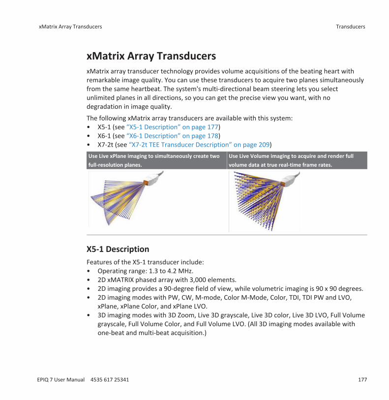
xMatrix Array TransducersxMatrix array transducer technology provides volume acquisitions of the beating heart withremarkable image quality. You can use these transducers to acquire two planes simultaneouslyfrom the same heartbeat. The system's multi-directional beam steering lets you selectunlimited planes in all directions, so you can get the precise view you want, with nodegradation in image quality.
The following xMatrix array transducers are available with this system:• X5-1 (see “X5-1 Description” on page 177)• X6-1 (see “X6-1 Description” on page 178)• X7-2t (see “X7-2t TEE Transducer Description” on page 209)Use Live xPlane imaging to simultaneously create twofull-resolution planes.
Use Live Volume imaging to acquire and render fullvolume data at true real-time frame rates.
X5-1 DescriptionFeatures of the X5-1 transducer include:• Operating range: 1.3 to 4.2 MHz.• 2D xMATRIX phased array with 3,000 elements.• 2D imaging provides a 90-degree field of view, while volumetric imaging is 90 x 90 degrees.• 2D imaging modes with PW, CW, M-mode, Color M-Mode, Color, TDI, TDI PW and LVO,
xPlane, xPlane Color, and xPlane LVO.• 3D imaging modes with 3D Zoom, Live 3D grayscale, Live 3D color, Live 3D LVO, Full Volume
grayscale, Full Volume Color, and Full Volume LVO. (All 3D imaging modes available withone-beat and multi-beat acquisition.)
xMatrix Array Transducers Transducers
EPIQ 7 User Manual 4535 617 25341 177
X6-1 DescriptionFeatures of the X6-1 transducer include:• Operating range: 1.5 to 6 MHz.• Biopsy capable.• Internal temperature monitoring.• 2D xMATRIX phased array with more than 9,000 elements.• 2D imaging provides a 100-degree field of view, while volumetric imaging is 90 x 90
degrees.• 2D imaging modes with Tissue Harmonic Imaging, M-mode, PW, Color, and CPA.• 3D and 4D imaging modes with xPlane, Elevation Compounding, single-sweep 3D grayscale,
Color, CPA, Directional CPA, live 4D grayscale imaging, 3D Panoramic, and iSTIC grayscaleand color with automated heart rate estimation.
Transducer MaintenanceTransducers require proper care, cleaning, and handling. Reasonable care includes inspection,cleaning, and disinfection or sterilization, as necessary.
Inspect the transducer cable, case, and lens before each use. Check for cracks or other damagethat jeopardizes the integrity of the transducer. Report any damage to your Philips customerservice representative, and discontinue use of the transducer.
For all information on transducer cleaning and disinfection, see the “Transducer Care” section.For all information about the use of acoustic coupling gels, see “Ultrasound Transmission Gels”on page 184.
CAUTIONSome ultrasound coupling gels, as well as some solutions for precleaning, disinfecting, andsterilizing can damage a transducer. Before using a gel or solution on a transducer, see“Ultrasound Transmission Gels” on page 184 or the “Transducer Care” section. You can alsocontact your local Philips representative. For contact information, see “Customer Service” onpage 22.
Transducers xMatrix Array Transducers
178 EPIQ 7 User Manual 4535 617 25341
If you encounter poor image quality or transducer problems, see “Troubleshooting” on page295.
Acoustic ArtifactsThe transducer adds its own signature to the echo information in the form of beam widtheffects, axial resolution limitations, and frequency characteristics. The control choices made bythe sonographer that affect amplification, signal processing, and echo signal display can lead tosignificant differences in the displayed appearance of echo data. Following is a brief discussionof acoustic artifacts. An understanding of the physical basis for the production of signalsdisplayed on ultrasound images is helpful in minimizing artifacts on images and interpreting theresults of studies.
An artifact is an echo displayed in a different position than its corresponding reflector in thebody. Artifacts can also be caused by intervening tissue properties. Artifacts can originate fromexternal noise, reverberations, multi-path reflections, or misadjusted equipment. They can alsocome from the ultrasonic beam geometry and unusual changes in beam intensity. Artifacts andtheir manifestations are listed below, and following are some definitions of various artifacts.• Added objects displayed as speckle, section thickness, reverberation, mirror image, comet
tail, or ring down• Missing objects due to poor resolution• Incorrect object brightness due to shadowing or enhancement• Incorrect object location due to refraction, multi-path reflections, side lobes, grating lobes,
speed error, or range ambiguity• Incorrect object size due to poor resolution, refraction, or speed error• Incorrect object shape due to poor resolution, refraction, or speed error
Acoustic saturation occurs when received signals reach a system's high-amplitude limit. At thatpoint the system becomes unable to distinguish or display signal intensities. At the point ofsaturation, increased input will not increase output.
Aliasing occurs when the detected Doppler frequency exceeds the Nyquist limit. It ischaracterized on the spectral display by the Doppler peaks going off the display, top or bottom,and then continuing on the other side of the baseline. On the Color display an immediatechange in color from one Nyquist limit to the other is seen.
Acoustic Artifacts Transducers
EPIQ 7 User Manual 4535 617 25341 179
Comet tail is a form of reverberation artifact produced when two or more strong reflectors areclose together and have a high propagation speed. In this case, sound does not travel directly toa reflector and back to the transducer; and a strong linear echo appears at the reflector andextends deeper than the reflector.
Enhancement is an increased relative amplitude of echoes caused by an intervening structureof low attenuation.
Focal enhancement, also known as focal banding, is the increased intensity in the focal regionthat appears as a brightening of the echoes on the display.
Mirror imaging artifact is most commonly seen around the diaphragm; this artifact results fromsound reflecting off another reflector and back.
Mirroring is the appearance of artifacts on a spectral display when there is improper separationof forward and reverse signal processing channels. Consequently, strong signals from onechannel mirror into the other.
Multi-path positioning and refraction artifacts describe the situation in which the paths to andfrom a reflector are different. The longer the sound takes traveling to or from a reflector, thegreater the axial error in reflector positioning (increased range). Refraction and multi-pathpositioning errors are normally relatively small and contribute to general degradation of theimage rather than to gross errors in object location.
Propagation speed errors occur when the assumed value for propagation speed by theultrasound system is incorrect. If the actual speed is greater than that assumed, the calculateddistance to a reflector is too small, and the reflector will be displayed too far from thetransducer. Speed error can cause a structure to be displayed with incorrect size and shape.
Range ambiguity can occur when reflections are received after the next pulse is transmitted. Inultrasound imaging, it is assumed that for each pulse produced, all reflections are receivedbefore the next pulse is sent out. The ultrasound system calculates the distance to a reflectorfrom the echo arrival time assuming that all echoes were generated by the last emitted pulse.The maximum depth to be imaged unambiguously by the system determines its maximumpulse repetition frequency.
Reverberation is the continuing reception of a particular signal because of reverberation ratherthan reflection from a particular acoustic interface. This phenomenon is analogous to the effectcreated by mirrors positioned on opposite walls when an object, a head for instance, is placed
Transducers Acoustic Artifacts
180 EPIQ 7 User Manual 4535 617 25341
between the mirrors. The image of the head is reflected back and forth infinitely between thetwo mirrors, creating the optical illusion of multiple heads. Reverberations are easilyidentifiable, because they are equally spaced on the display.
Scattering is the diffuse, low-amplitude sound waves that occur when acoustic energy reflectsoff tissue interfaces smaller than a wavelength. In diagnostic ultrasound, Doppler signals comeprimarily from acoustic energy back-scattered from red blood cells.
Shadowing is the reduction in echo amplitude from reflectors that lie behind a stronglyreflecting or attenuating structure. This phenomenon occurs when scanning a lesion orstructure with an attenuation rate higher than that of the surrounding tissue. The lesion causesa decrease in beam intensity, which results in decreased echo signals from the structuresbeyond the lesion. Consequently, a dark cloud behind the lesion image forms on the display.This cloud, or shadow, is useful as a diagnostic clue.
Side lobes (from single-element transducers) and grating lobes (from array transducers) causeobjects that are not directly in front of the transducer to be displayed incorrectly in lateralposition.
Speckle appears as tissue texture close to the transducer but does not correspond to scatterersin tissue. It is produced by ultrasound wave interference and results in general imagedegradation.
Spectral broadening is a display phenomenon that occurs when the number of energy-bearingFourier frequency components increases at any given point in time. As a consequence, thespectral display is broadened. Spectral broadening can indicate the disturbed flow caused by alesion, and therefore it is important diagnostically. However, broadening can also result frominteraction between flow and sample volume size, in which case it is an artifact.
Speed of sound artifacts occur if the sound propagation path to a reflector is partially throughbone, and the speed of sound is greater than in the average soft tissue. Echo positionregistration artifacts will be produced. Reflectors appear closer to the transducer than theiractual distance because of this greater speed of sound, resulting in a shorter echo transit timethan for paths not containing bone.
Acoustic Artifacts in 3D ImagingAcquisition, rendering, and editing artifacts are specific to 3D volume images. Acquisitionartifacts are related to patient motion, organ motion, or position-sensing errors. Renderingartifacts include elimination of structures by limiting the region of interest boundaries,
Acoustic Artifacts Transducers
EPIQ 7 User Manual 4535 617 25341 181
thresholding that eliminates structures, and adjacent structure artifacts that add additionalinformation or hide structures. Editing artifacts result from data deleted from a renderedimage.
Color and Color Power Angio artifacts relating to gain may also be confusing in renderedimages. A color flash artifact can occur when the gain is set high and the transducer or patientmoves. When the gain is set too high, the color ROI box fills with color flash. When the gain isset low, color bleed can occur. When the gain is set too low, insufficient color data renders theimage undiagnosable.
Color gain, directional, and motion artifacts can present themselves in 3D imaging. Color andColor Power Angio gain artifacts are mainly related to the use of excessive gain resulting inrandom color patterns in the 3D image that might be interpreted as diagnostically significant.Directional artifacts are due to aliasing or directional confusion: The velocity range must be setproperly, and the relationship between the transducer orientation and the flow vector must beunderstood. Patient motion can produce flash artifacts that are less obvious in 3D images thanin 2D imaging.
Dropout and shadowing are present in 3D imaging although they are more difficult torecognize due to different and unfamiliar displays. Acoustic shadowing and other artifacts lookvery different when displayed in 3D volumes and may be more difficult to recognize than onstandard 2D imaging. Those artifacts may produce apparent defects, such as limb abnormalitiesor facial clefts, where they are not present. Acquiring data from multiple orientations mayavoid artifacts of this type.
Fetal limb deficit artifacts are specific to 3D volume images. Partially absent fetal limb boneshave been demonstrated. One explanation for the missing limbs was shadowing caused byadjacent skeletal structures. Overcoming the limb deficit artifact can be accomplished bychanging the transducer position and the acquisition plane.
Motion artifacts in 3D volumes can be caused by patient motion, fetal movement, cardiacmotion, and movement of adjacent structures. Patient motion can produce flash artifacts thatare more obvious in 3D images than in 2D imaging.
Pseudoclefting and pseudonarrowing artifacts may be related to limb deficit artifacts. Artifactsmay be present in 3D imaging of the fetal face. Being aware of pseudoclefting of the fetal faceand pseudonarrowing of the fetal spine can help the sonographer understand and identifythese artifacts. As with 2D imaging, it is important to verify putative physical defects by usingadditional images and other modalities.
Transducers Acoustic Artifacts
182 EPIQ 7 User Manual 4535 617 25341
Resolution, attenuation, and propagation artifacts are all common to 3D imaging. Carefulscrutiny of the original 2D images is necessary to identify and preclude these types of artifactsfrom the 3D volume image.
Transducer CoversTo prevent contamination by blood-borne pathogens, sterile transducer covers are required forintraoperative and biopsy procedures; in China, sterile covers are also required for transrectal,intravaginal, and transesophageal procedures. Protective covers are recommended fortransrectal, intravaginal, and transesophageal procedures; the protective covers are mandatoryin China and Japan. Philips recommends the use of qualified covers.
For procedures for using transducer covers, see the instructions provided with the covers.
WARNINGLatex and talc are commonly used in sheaths marketed to help with infection control intransesophageal, endocavity, and intraoperative imaging applications and during biopsies.Examine the packaging to confirm latex and talc content. Studies have shown that patientscan experience allergic reactions with natural rubber latex. See the FDA Medical Alert, March29, 1991, reprinted in “FDA Medical Alert on Latex” on page 49.
WARNINGIn intraoperative applications, sterilized transducers should be used with sterile gel and asterile transducer cover.
WARNINGDo not apply the transducer cover until you are ready to perform the procedure.
WARNINGInspect transducer covers before and after use.
Transducer Covers Transducers
EPIQ 7 User Manual 4535 617 25341 183
WARNINGIf the sterile transducer cover becomes compromised during an intraoperative applicationinvolving a patient with Creutzfeldt-Jakob disease, follow the recommendations described in“Transmissible Spongiform Encephalopathy” on page 257.
WARNINGTransducer covers are disposable and must not be reused.
WARNINGIf an installed transducer cover is cut or contaminated before use, the probe should becleaned and disinfected or sterilized, and a new sterile cover installed.
Ultrasound Transmission GelsFor proper transmission of the acoustic beam, use the ultrasound transmission gel supplied byor recommended by Philips, or another glycol-, glycerol-, or water-based acoustic couplingmedium. Products that do not contain mineral oil are acceptable for use. Never use lotion-based products.
WARNINGDo not apply the transducer gel until you are ready to perform the procedure. Transducersshould not be left soaking in gel.
WARNINGFor intraoperative applications, use only the Sterile Aquasonic or Sterile Ultraphonic gelprovided with the transducer cover.
CAUTIONDo not use gels that contain mineral oil or lotion. Such products may damage the transducerand void the warranty.
Transducers Ultrasound Transmission Gels
184 EPIQ 7 User Manual 4535 617 25341

CAUTIONGels listed here are recommended because of their chemical compatibility with productmaterials.
Some recommended gels include:• Aquasonic 100• Aquasonic Clear• Carbogel-ULT• ECG Gel (Nicom)• Nemidon Gel• Scan
For additional compatibility information, call Philips at 800-722-9377 (North America) or yourlocal Philips Ultrasound representative (outside North America).
Transducer StorageUse the appropriate guidelines for storing transducers for transport, and daily and long-termstorage.
Storage for Transport If a carrying case is provided with your transducer, always use the carrying case to transport thetransducer from one site to another. Follow these guidelines to properly store transducers fortransport:• Make sure that the transducer is clean and disinfected before placing it in the case to avoid
contaminating the foam that lines the carrying case.• Place the transducer in the case carefully to prevent kinking of the cable.• Before closing the lid, make sure no part of the transducer is protruding from the case.• Wrap the case in plastic material containing air pockets (such as Bubble Wrap material), and
pack the wrapped case in a cardboard carton.• To avoid damaging the shaft or steering mechanism of TEE transducers, do not bend or coil
the flexible shaft of the transducer in less than a 0.30-m (1-ft) diameter circle.
Transducer Storage Transducers
EPIQ 7 User Manual 4535 617 25341 185
Daily and Long-Term StorageFollow these guidelines to protect your transducer:• Always store transducers in the transducer holders on the side of your system or on a
securely mounted wall rack when you are not using them.• Ensure the transducer holders are clean before storing transducers (see “Disinfecting
System Surfaces” on page 290).• Avoid storing transducers in areas of temperature extremes or in direct sunlight.• Store transducers separately from other instruments to avoid inadvertent transducer
damage.• When storing transducers, use the cable-management clips to secure the transducer cable.• Before storing transducers, make sure they are thoroughly dry.• For TEE transducers, be sure the distal tip is straight and protected before storing the
transducer.• Never store a TEE transducer in the carrying case, except to transport it.
Transducers Transducer Storage
186 EPIQ 7 User Manual 4535 617 25341
Intraoperative TransducersAn intraoperative transducer is used during surgery to help the surgeon locate and visualizeanatomical structures, to visualize blood flow patterns and quantify velocities, and to imageand measure anatomical and physiological parameters of interest to the surgeon.
The system supports the L15-7io transducer for use in intraoperative applications.
WARNINGAll intraoperative transducers are designed to be defibrillator safe in accordance with IEC60601-1. Nevertheless, always remove the transducer from the patient before defibrillation.
NOTEIntraoperative transducers will be unavailable in the US and Canada until regulatory clearance isreceived.
Operators of Intraoperative TransducersPhilips intraoperative transducers are designed to be used under the guidance of physicianswho are properly trained in intraoperative ultrasound imaging techniques according tocurrently approved relevant medical practices. Philips recommends that physicians operatingany Philips intraoperative transducer have the following qualifications:• Proficiency in recognizing and interpreting imaging patterns.• Thorough familiarity with the safe operation, care, and maintenance of the ultrasound
system and the intraoperative transducers.• Thorough familiarity with the latest intraoperative methods through literature and
seminars.
9
Operators of Intraoperative Transducers Intraoperative Transducers
EPIQ 7 User Manual 4535 617 25341 187

Intended Uses for Intraoperative TransducersIntraoperative studies are performed by surgeons, anesthesiologists, or sonographers to obtainimages that can be used for the following purposes:• Helping a surgeon locate and visualize anatomical structures before, during, or after a
surgical procedure• Helping a surgeon visualize blood flow patterns and quantify velocities before, during, or
after a surgical procedure• Imaging and measuring anatomic and physiologic parameters before, during, or after a
surgical procedure
WARNINGIntraoperative transducers used in animal studies should not be used on humans. Transducerdisinfection procedures for cross-usage between animals and humans have not beenvalidated.
Patient Safety During Intraoperative Studies To operate an intraoperative transducer, you must be under the guidance of a physician who isproperly trained in intraoperative ultrasound imaging techniques, according to currentlyapproved relevant medical practices. You also must be thoroughly familiar with the safeoperation, care, and maintenance of the ultrasound system used with the transducer, as well asproficient at interpreting the images generated.
To help ensure patient safety when using an intraoperative transducer, observe the followingguidelines:• Scrutinize the entire transducer before each use. (See the “Transducer Care” section.)• Use mandatory protective equipment, including an approved sterile protective transducer
cover, during intraoperative studies. For information about using transducer covers, see“Preparing Transducers for Intraoperative Use” on page 191.
• Operate the transducer properly.
Intraoperative Transducers Intended Uses for Intraoperative Transducers
188 EPIQ 7 User Manual 4535 617 25341
• Do not allow water or other liquids to drip onto the transducer connector, the interior ofthe system, or the keyboard.
• Maintain a sterile field.
WARNINGAll intraoperative studies must be performed with a Type CF classified transducer. If yourtransducer is not labeled Type CF on the transducer connector, contact your Philipsservice representative.
WARNINGBe sure to use a market-approved sterile transducer cover and sterile ultrasoundtransmission gel when performing all intraoperative studies.
WARNINGAlways remove the transducer from the patient before defibrillation.
Patient-Contact PartsLatex is commonly used in sheaths marketed to help with infection control in transesophageal,endocavity, and intraoperative imaging applications and during biopsies. Examine the packagingto confirm latex content. Studies have shown that patients can experience allergic reactionswith natural rubber latex. See “FDA Medical Alert on Latex” on page 49.
NOTEThe ultrasound system and transducers discussed here do not contain natural rubber latex thatcontacts humans. Natural rubber latex is not used on any Philips ultrasound transducers.
Patient Safety During Intraoperative Studies Intraoperative Transducers
EPIQ 7 User Manual 4535 617 25341 189
Preventing Intraoperative Transducer Problems
WARNINGIf you find any signs of damage to the transducer, patient safety may be compromised. Donot use the transducer, and contact your Philips service representative.
Meticulous inspection and correct and careful operation of intraoperative transducers areimperative to patient safety. The situations listed here affect safe operation as well as theability to service mechanical problems under the Philips warranty or service contract.Transducer repairs necessitated by misuse are not covered and can be very costly, oftenrequiring complete disassembly and rebuilding of the transducer.
There are three primary areas of transducer misuse:• Cuts and abrasions on the transducer insulation and lens from sharp instruments such as
scalpels, scissors, and clamps• Improper disinfection techniques, causing fluid to enter the transducer or damage
transducer materials• Damage caused by dropping the transducer on a hard surface
To minimize the chance of damage, Philips strongly recommends that you clearly post stringentprotocols for the care of intraoperative transducers, based on the information provided here.
L15-7io DescriptionThe L15-7io transducer is described here. For more information on connecting, activating,caring for, and maintaining transducers, see the “Transducers” and “Transducer Care” sections.
Intraoperative Transducers Preventing Intraoperative Transducer Problems
190 EPIQ 7 User Manual 4535 617 25341
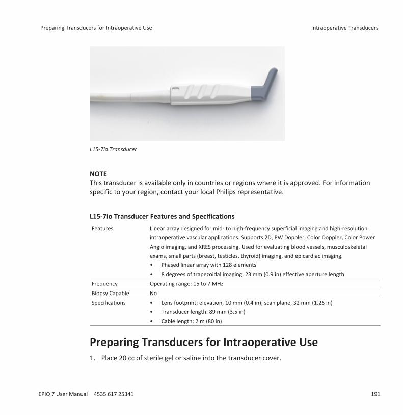
L15-7io Transducer
NOTEThis transducer is available only in countries or regions where it is approved. For informationspecific to your region, contact your local Philips representative.
L15-7io Transducer Features and SpecificationsFeatures Linear array designed for mid- to high-frequency superficial imaging and high-resolution
intraoperative vascular applications. Supports 2D, PW Doppler, Color Doppler, Color PowerAngio imaging, and XRES processing. Used for evaluating blood vessels, musculoskeletalexams, small parts (breast, testicles, thyroid) imaging, and epicardiac imaging.• Phased linear array with 128 elements• 8 degrees of trapezoidal imaging, 23 mm (0.9 in) effective aperture length
Frequency Operating range: 15 to 7 MHzBiopsy Capable NoSpecifications • Lens footprint: elevation, 10 mm (0.4 in); scan plane, 32 mm (1.25 in)
• Transducer length: 89 mm (3.5 in)• Cable length: 2 m (80 in)
Preparing Transducers for Intraoperative Use1. Place 20 cc of sterile gel or saline into the transducer cover.
Preparing Transducers for Intraoperative Use Intraoperative Transducers
EPIQ 7 User Manual 4535 617 25341 191
2. Carefully inspect each transducer cover before use, and discard it if you find tears orblemishes. Also inspect each transducer cover after use. If you find a tear, the patient or thetransducer may have been contaminated.
3. Insert the transducer into the transducer cover and unfurl the transducer cover until itcovers the transducer and its cable. The cover must be unfurled far enough to maintain thesterile field.
4. Use a sterile elastic band or clip to hold the proximal end of the transducer cover in place.5. Ensure that wrinkles and bubbles over the face of the transducer are minimized. Check the
transducer cover for tears or damage before proceeding.6. When operating the transducer, make sure that proper orientation is maintained to avoid
interpretation confusion.
NOTETo achieve good acoustic contact, make sure that the imaging surface is moist.
NOTEImaging improves with adequate coupling between the patient surface and the transducer-cover surface. Sterile water is a good acoustic-coupling agent during surgery.
Disposable DrapesDuring studies in which you believe contamination of the ultrasound system can occur, Philipsrecommends that you take universal precautions and cover the system with a disposable drape.Consult your hospital’s rules regarding equipment use in the presence of infectious disease.
Accessories for Intraoperative TransducersFor information on ordering accessories, see “Supplies and Accessories” on page 21.
Electrical Safety and Intraoperative TransducersAll Philips ultrasound systems and transducers comply with common medical device electricalsafety standards.
Intraoperative Transducers Preparing Transducers for Intraoperative Use
192 EPIQ 7 User Manual 4535 617 25341
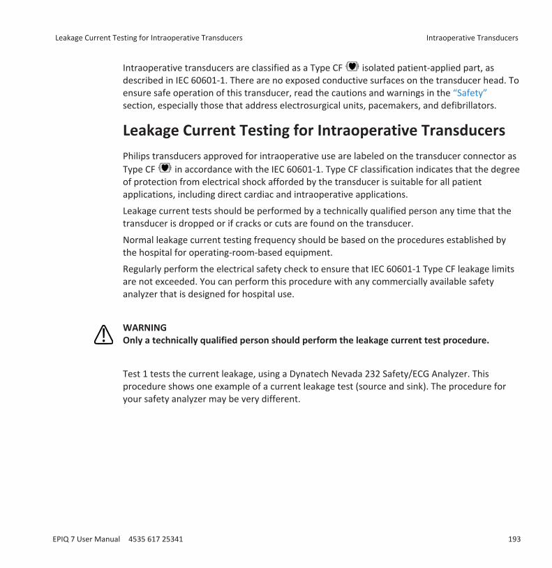
Intraoperative transducers are classified as a Type CF isolated patient-applied part, asdescribed in IEC 60601-1. There are no exposed conductive surfaces on the transducer head. Toensure safe operation of this transducer, read the cautions and warnings in the “Safety”section, especially those that address electrosurgical units, pacemakers, and defibrillators.
Leakage Current Testing for Intraoperative TransducersPhilips transducers approved for intraoperative use are labeled on the transducer connector asType CF in accordance with the IEC 60601-1. Type CF classification indicates that the degreeof protection from electrical shock afforded by the transducer is suitable for all patientapplications, including direct cardiac and intraoperative applications.
Leakage current tests should be performed by a technically qualified person any time that thetransducer is dropped or if cracks or cuts are found on the transducer.
Normal leakage current testing frequency should be based on the procedures established bythe hospital for operating-room-based equipment.
Regularly perform the electrical safety check to ensure that IEC 60601-1 Type CF leakage limitsare not exceeded. You can perform this procedure with any commercially available safetyanalyzer that is designed for hospital use.
WARNINGOnly a technically qualified person should perform the leakage current test procedure.
Test 1 tests the current leakage, using a Dynatech Nevada 232 Safety/ECG Analyzer. Thisprocedure shows one example of a current leakage test (source and sink). The procedure foryour safety analyzer may be very different.
Leakage Current Testing for Intraoperative Transducers Intraoperative Transducers
EPIQ 7 User Manual 4535 617 25341 193
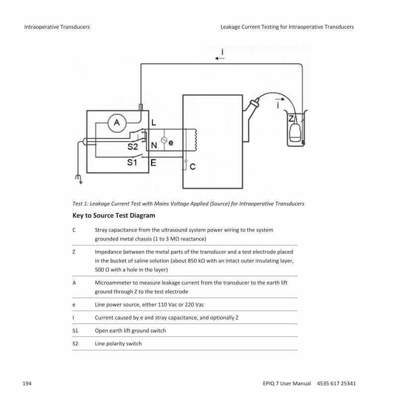
Test 1: Leakage Current Test with Mains Voltage Applied (Source) for Intraoperative Transducers
Key to Source Test Diagram
C Stray capacitance from the ultrasound system power wiring to the systemgrounded metal chassis (1 to 3 MΩ reactance)
Z Impedance between the metal parts of the transducer and a test electrode placedin the bucket of saline solution (about 850 kΩ with an intact outer insulating layer,500 Ω with a hole in the layer)
A Microammeter to measure leakage current from the transducer to the earth liftground through Z to the test electrode
e Line power source, either 110 Vac or 220 Vac
I Current caused by e and stray capacitance, and optionally Z
S1 Open earth lift ground switch
S2 Line polarity switch
Intraoperative Transducers Leakage Current Testing for Intraoperative Transducers
194 EPIQ 7 User Manual 4535 617 25341
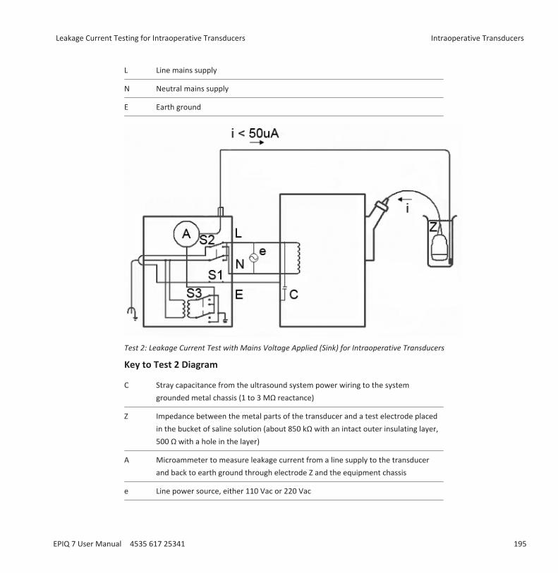
L Line mains supply
N Neutral mains supply
E Earth ground
Test 2: Leakage Current Test with Mains Voltage Applied (Sink) for Intraoperative Transducers
Key to Test 2 Diagram
C Stray capacitance from the ultrasound system power wiring to the systemgrounded metal chassis (1 to 3 MΩ reactance)
Z Impedance between the metal parts of the transducer and a test electrode placedin the bucket of saline solution (about 850 kΩ with an intact outer insulating layer,500 Ω with a hole in the layer)
A Microammeter to measure leakage current from a line supply to the transducerand back to earth ground through electrode Z and the equipment chassis
e Line power source, either 110 Vac or 220 Vac
Leakage Current Testing for Intraoperative Transducers Intraoperative Transducers
EPIQ 7 User Manual 4535 617 25341 195
I Current caused by e and stray capacitance, and optionally Z
S1 Open earth lift ground switch
S2 Line polarity switch
S3 Isolation test button
L Line mains supply
N Neutral mains supply
E Earth ground
Testing Intraoperative Transducer Leakage Current (Source)This test checks leakage current without mains voltage applied. For a diagram of this test, Test1, see “Leakage Current Testing for Intraoperative Transducers” on page 193.
WARNINGElectrical shock hazard: Do not touch the lead that you connect to the safety analyzer in step7.
1. Plug the safety analyzer into the power source.2. Plug the ultrasound system into the safety analyzer.3. Connect the transducer being tested to the ultrasound system.4. Immerse 5 cm (2 in) of the transducer in saline solution.5. Set the safety analyzer Mode switch to the ECG position.6. Set the safety analyzer Leads switch to the ALL (all ECG leads) position.7. Connect a lead to any ECG terminal on the safety analyzer, and immerse the other end into
the saline solution.8. Set the safety analyzer Line Polarity switch to Normal.9. Note the normal condition leakage reading.10. Hold the safety analyzer Ground Open switch in the Open position (single fault condition),
and note the leakage reading.11. Repeat step 9 and step 10 with the Polarity switch in the Reverse position. These are the
applicable limits:
Intraoperative Transducers Leakage Current Testing for Intraoperative Transducers
196 EPIQ 7 User Manual 4535 617 25341
• 10 µA RMS (normal condition)• 50 µA RMS (single fault condition)
Testing Intraoperative Transducer Leakage Current (Sink)
WARNINGThere is considerable hazard in performing this test. Use precautionary measures to avoidaccidental contact with line voltage. In addition, any time that the ground connection hasbeen opened, do not touch the chassis or the patient cable during the test.
This test checks leakage current with mains voltage applied. For a diagram of this test, Test 2,see “Leakage Current Testing for Intraoperative Transducers” on page 193.1. Plug the safety analyzer into the power source.2. Plug the ultrasound system into the safety analyzer.3. Connect the transducer being tested to the ultrasound system.4. Immerse 5 cm (2 in) of the transducer in saline solution.5. Set the safety analyzer Mode switch to the ECG position.6. Set the safety analyzer Leads switch to the Isolation Test position.7. Connect a lead to any ECG terminal on the safety analyzer. Leave the other end of the lead
disconnected for now.8. Press and hold the Isolation Test button and note the leakage reading. This is the correction
factor that will be subtracted from the final reading.9. Immerse the other end of the lead into the saline solution.10. Press and hold the Isolation Test button and take the leakage reading again.11. Subtract the correction factor found in step 8 to get the accurate leakage measurement.
The leakage must be less than 50 µA RMS.
Leakage Current Testing for Intraoperative Transducers Intraoperative Transducers
EPIQ 7 User Manual 4535 617 25341 197

Intraoperative Transducers Leakage Current Testing for Intraoperative Transducers
198 EPIQ 7 User Manual 4535 617 25341

Transesophageal TransducersA transesophageal echocardiography (TEE) study is performed with a transducer mounted in agastroscope, which is positioned in the esophagus or stomach. TEE transducers offer imagesthat are unobstructed by lungs and ribs, making them important diagnostic tools for conditionsthat transthoracic echocardiography cannot adequately image.
All transesophageal transducers are rated minimum IPX1 (control area) and IPX7 (endoscopearea) in accordance with IEC 60529.
The system supports the compact X7-2t and S7-3t TEE transducers. The imaging array in theX7-2t and the S7-3t transducers can be rotated electronically using controls on the transduceror on the control panel.
WARNINGAll TEE transducers are designed to be defibrillator safe in accordance with IEC 60601-1.Nevertheless, always remove the transducer from the patient before defibrillation.
Operators of TEE TransducersPhilips TEE transducers are designed for use under the guidance of physicians who are properlytrained in esophagogastroscopic techniques, according to currently approved relevant medicalpractices. Philips recommends that physicians operating any Philips TEE transducer have thefollowing qualifications:• Proficiency in recognizing and interpreting transesophageal imaging patterns• Thorough familiarity with the safe operation, care, and maintenance of the ultrasound
system and TEE transducers• Thorough familiarity with the latest TEE methods through literature and seminars
10
Operators of TEE Transducers Transesophageal Transducers
EPIQ 7 User Manual 4535 617 25341 199

Patient Safety During TEE StudiesPhilips recommends that you practice using the TEE transducer controls before performing anyprocedure mentioned here. You must also be thoroughly familiar with the safe operation, care,and maintenance of the ultrasound imaging system used with the TEE transducer, as well asproficient at interpreting the images generated.
You can help ensure patient safety when using a TEE transducer by following these guidelines:• Have a backup system present during TEE exams to ensure completion of the exam in the
event that the primary system fails.• Use informed judgment when selecting patients for TEE studies. See “Patient Selection for
TEE Transducer Use” on page 224.• Verbally prepare each patient for the procedure before the study. See "Preparing Patients
for TEE Studies" in the Help.• Scrutinize the entire transducer, turn on the system, and test all of the transducer controls
and related system controls, before inserting the TEE transducer into the patient'sesophagus. See “Checking the TEE Transducer” on page 223.
• Insert, remove, and operate the transducer properly.• Ensure that the transducer handle does not rest on or touch the patient.• Use protective equipment, such as a bite guard and a market-approved sterile transducer
cover during a TEE study. See “TEE Accessories and Supplies” on page 233.• Do not allow water or other liquids to come in contact with the interior of the system, the
interior of the transducer connector, the inside of the transducer control handle, or to driponto the keyboard.
• Minimize the possibility of transducer tip fold-over. This problem has occurred rarely, butits consequences can be serious. See “Tip Fold-Over” on page 226.
To prevent tissue damage such as pressure necrosis, gastroesophageal lacerations, bleeding,tearing of adhesions, ligament damage, and perforation, observe the following warnings andcautions.
WARNINGNever apply excessive force when inserting or withdrawing a TEE transducer, or whenoperating the transducer deflection controls.
Transesophageal Transducers Patient Safety During TEE Studies
200 EPIQ 7 User Manual 4535 617 25341
WARNINGDo not allow the transducer to remain at a maximum deflection for long periods of time.
WARNINGLock medial/lateral movement of the TEE transducer during insertion.
WARNINGWhenever the TEE transducer is not being used during a procedure, ensure that it is infreewheeling mode and unplugged from the system.
WARNINGTo prevent tissue damage, Philips recommends that the tip of the TEE transducer bestraightened and both detent brakes released before you reposition the transducer orwithdraw the transducer from the patient. In the neutral position, the tip is straight when theindicators on the control wheels are aligned and point toward the center of the array rotationbutton.
WARNINGBite guards are mandatory; protective transducer covers are recommended for TEEtransducers, but in China and Japan, the covers are mandatory. See “Electrical Safety and TEETransducers” on page 205.
CAUTIONTo avoid damaging gastroscope cables, be sure that the distal tip of the transducer is in theneutral (straight) position when inserting a transducer into, or removing it from, thetransducer cover.
Patient Safety During TEE Studies Transesophageal Transducers
EPIQ 7 User Manual 4535 617 25341 201
The TEE transducers are classified as Type BF isolated patient-applied parts, as described in IEC60601-1. There are no exposed conductive surfaces distal to the transducer handle. To ensuresafe operation of this transducer, read the cautions and warnings in the “Safety” section,especially those that address electrosurgical units, pacemakers, and defibrillators.
The following table summarizes patient safety problems, describes how to prevent them, andlists the sections in this manual where details are provided.
WARNINGIf you encounter an irregularity not listed in the following table, do not use the transducer.Potentially serious consequences could result. Contact your Philips representative.
Ensuring Patient Safety During TEE StudiesProblem Effect on Patient Prevention SeeMechanicaldamage
Severe trauma, cuts,bleeding, perforations
Inspect the transducer, using both sightand touch, before the study.
“Checking the TEETransducer” on page223
Electricaldamage
Esophageal burns Check the transducer for frayed insulation,kinks, or other abnormalities. Followprocedures for checking electrical safety.
“Electrical Safety andTEE Transducers” onpage 205
Biting, scrapingtransducer
Tooth damage,esophageal burns
Always use a bite guard. “Bite Guards” on page233
Insufficientcleaningprotocol
Spread of illness ordisease
Thoroughly clean and disinfect thetransducer after each use. Cover the tipand shaft with a transducer cover. Coverthe imaging system with a disposabledrape if highly pathogenic organisms areknown or suspected.
“Transducer Care”section
Transesophageal Transducers Patient Safety During TEE Studies
202 EPIQ 7 User Manual 4535 617 25341

Problem Effect on Patient Prevention SeeImproperinsertion orwithdrawal
Esophageal cuts,bleeding, ligamentdamage, perforations
To prevent improper insertion orwithdrawal when using a TEE transducer,never use force when inserting, removing,or manipulating the transducer. Duringinsertion, lock the medial/lateral controls.During withdrawal, release both brakes toplace both steering knobs in thefreewheeling position.
“TEE Study Guidelines”on page 225
Pressurenecrosis
Death of esophageallining tissue
Keep deflection controls in freewheelingmode and unplug the transducer from thesystem when not imaging. Minimize thepressure applied to deflection area anddistal tip. Do not let the distal tip displacea tissue area for more than 5 consecutiveminutes.
“TEE Study Guidelines”on page 225
Increasedtransducertemperature
Esophageal burns Use the TEE preset that has beenestablished to minimize the effects oftemperature. For febrile patients, use theAuto-Cool feature.
“Entering PatientTemperature” on page231
Improperpatient position
Transient unilateral vocalcord paralysis
Never use the transducer during anyprocedure requiring extreme neck flexion,such as sitting craniotomies.
“TEE Study Guidelines”on page 225
NonisolatedESUs
Electrical burns Only use isolated-output electrosurgicalunits (ESUs). The ESU label or service guideor your biomedical department shouldidentify whether or not the ESU is isolated.Unplug transducer from the system whenyou are not imaging.
“Electrical Safety andTEE Transducers” onpage 205
Defibrillationissues
Electrical burns Remove the transducer from the patientbefore defibrillation.
“Electrical Safety andTEE Transducers” onpage 205
Patient Safety During TEE Studies Transesophageal Transducers
EPIQ 7 User Manual 4535 617 25341 203
Patient-Contact PartsLatex is commonly used in sheaths marketed to help with infection control in transesophageal,endocavity, and intraoperative imaging applications and during biopsies. Examine the packagingto confirm latex content. Studies have shown that patients can experience allergic reactionswith natural rubber latex. See “FDA Medical Alert on Latex” on page 49.
NOTEThe ultrasound system and transducers discussed here do not contain natural rubber latex thatcontacts humans. Natural rubber latex is not used on any Philips ultrasound transducers.
Preventing TEE Transducer ProblemsMeticulous inspection and correct and careful operation of the TEE (transesophageal)transducer is imperative to patient safety. The situations listed here affect safe operation aswell as the ability to service mechanical problems under the Philips one-year warranty orservice contract. Transducer repairs necessitated by misuse of the transducer are not coveredand can be very costly, often requiring complete disassembly and rebuilding of the transducer.
There are three primary areas of transducer misuse:• Cuts and abrasions on the transducer and insulation from teeth or sharp instruments such
as scalpels, scissors, and clamps• Improper disinfection techniques, including allowing fluid to enter the connector or
transducer handle and the use of unapproved disinfectants• Consistently applying too much force to the control wheels of a TEE transducer, which can
break the steering mechanism
Review the following table to familiarize yourself with specific problems, to learn how to avoidthem, and to identify the sections in this manual where details are provided. Philips alsostrongly recommends that you clearly post stringent protocols for TEE transducer care, basedon the information in this manual, to minimize the chance of damage.
Transesophageal Transducers Patient Safety During TEE Studies
204 EPIQ 7 User Manual 4535 617 25341

WARNINGFor any other irregularity not listed in the following table, do not use the transducer.Potentially serious consequences could result. Contact your Philips representative.
Preventing TEE Transducer Equipment ProblemsProblem Effect on Equipment Prevention SeeCurrent leakage Serious electrical hazards Check the transducer for cuts, frayed
insulation, kinks, or otherabnormalities.
“Checking the TEETransducer” on page223
Biting transducer Mechanical and electricalhazards
Cover the patient's teeth with a biteguard (mandatory). Cover the distal tipand flexible shaft with a transducercover (recommended, but in China andJapan, mandatory).
“Bite Guards” on page233
Forcing deflectioncontrols
Steering mechanism broken Operate the deflection controls gently. “X7-2t DeflectionControls” on page 211and “S7-3t TEEControls” on page 218
Incorrect storage Possible damage to highlysensitive elements, cuts inflexible shaft
Suspend the transducer from a wall-mounted rack and the distal tip with atip protector when not in use.
“Transducer Storage”on page 185
Internal exposureto liquids
Severe transducer damagethat affects the imagequality, the steeringmechanism, and electricalsafety
Never sterilize the transducer by usingbleach, steam, heat, or ethylene oxide(EtO). Never immerse the steeringmechanism in any disinfectant or liquid.
“Transducer Care”section
Electrical Safety and TEE TransducersThe ultrasound system and its transducers comply with common medical device electricalsafety standards.
For electrical safety information about TEE transducers, see “Leakage Current and TEETransducers” on page 206 and “Reducing Risks of Using TEE Transducers” on page 206.
Electrical Safety and TEE Transducers Transesophageal Transducers
EPIQ 7 User Manual 4535 617 25341 205
For safety information on electrosurgical units, pacemakers, defibrillators, and related topics,see “Electrical Safety” on page 29.
Leakage Current and TEE Transducers
For the TEE transducers discussed in this document, the insertion tube and tip are Type BF ,as described in IEC 60601-1. There are no exposed conductive surfaces distal to the transducerhandle. Within the flexible shaft, all active circuits and conductors are surrounded by a chassis-grounded shield that runs the length of the transducer.
If the outer layer of the shaft is punctured or cracked, a patient’s esophagus could be exposedto chassis leakage current. This leakage current is not hazardous provided that the groundconnector (third wire) in the ultrasound system power cable is intact and connected to aproperly grounded wall outlet. Even if the ground connector breaks, leakage current is incompliance with the limits noted in IEC 60601-1.
Leakage hazards are further reduced when the ultrasound system is plugged into an isolatedpower outlet, which is standard in most operating rooms.
Reducing Risks of Using TEE Transducers
WARNINGBefore defibrillation, if you cannot remove the transducer from the patient, alwaysdisconnect invasive transducers that remain in contact with the patient from the system.
To reduce the possibility of electrical risks associated with use of TEE transducers, follow theserecommendations:• Visually and tactually inspect a TEE transducer for bumps, cracks, and cuts before each TEE
exam. A small bump on the shaft surface could indicate that a strand from the groundshield has broken and is beginning to puncture the outer layer. If you suspect a problemwith the flexible shaft, perform the electrical safety check procedure. See “TEE LeakageCurrent Test” on page 234.
• Use electrosurgical units (ESUs) that have isolated outputs. Return fault/ground faultdetection circuits provide additional protection. To determine if an ESU has an isolatedoutput, read the label on the ESU, see the ESU service guide, or ask a biomedical engineer.
Transesophageal Transducers Electrical Safety and TEE Transducers
206 EPIQ 7 User Manual 4535 617 25341
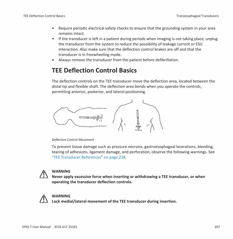
• Require periodic electrical safety checks to ensure that the grounding system in your arearemains intact.
• If the transducer is left in a patient during periods when imaging is not taking place, unplugthe transducer from the system to reduce the possibility of leakage current or ESUinteraction. Also make sure that the deflection control brakes are off and that thetransducer is in freewheeling mode.
• Always remove the transducer from the patient before defibrillation.
TEE Deflection Control Basics The deflection controls on the TEE transducer move the deflection area, located between thedistal tip and flexible shaft. The deflection area bends when you operate the controls,permitting anterior, posterior, and lateral positioning.
Deflection Control Movement
To prevent tissue damage such as pressure necrosis, gastroesophageal lacerations, bleeding,tearing of adhesions, ligament damage, and perforation, observe the following warnings. See“TEE Transducer References” on page 238.
WARNINGNever apply excessive force when inserting or withdrawing a TEE transducer, or whenoperating the transducer deflection controls.
WARNINGLock medial/lateral movement of the TEE transducer during insertion.
TEE Deflection Control Basics Transesophageal Transducers
EPIQ 7 User Manual 4535 617 25341 207
WARNINGWhenever the TEE transducer is not being used during a procedure, ensure that it is infreewheeling mode and unplugged from the system.
WARNINGDo not allow the TEE transducer to remain at a maximum deflection for long periods of time.
WARNINGTo prevent tissue damage, Philips recommends that the tip of the TEE transducer bestraightened and both detent brakes released before you reposition the transducer orwithdraw the transducer from the patient. In the neutral position, the tip is straight when theindicators on the control wheels are aligned and point toward the center of the array rotationbutton.
WARNINGBite guards are mandatory; protective covers are recommended for TEE transducers, exceptin China and Japan, where protective transducer covers are mandatory for TEE transducers.
WARNINGTo avoid damaging gastroscope cables, be sure that the distal tip of the transducer is in theneutral (straight) position when inserting a transducer into, or removing it from, thetransducer cover.
Transesophageal Transducers TEE Deflection Control Basics
208 EPIQ 7 User Manual 4535 617 25341

X7-2t TEE Transducer Description
X7-2t TEE Transducer
X7-2t TEE Transducer Features and SpecificationsFeatures PureWave technology sensor enables high-resolution imaging and 360-degree views
of the heart, unobstructed by lungs and ribs. Capable of 2D, 3D, Harmonic imaging,Live 3D, xPlane imaging, color Flow, steerable CW Doppler mode, and PW Dopplermode, frequency agility, and electrocautery suppression. Tip surface constantlymonitored for patient safety. Convenient hanging ring.
Specifications • Tip: 1.5 cm (0.6 in) wide, 3.5 cm (1.4 in) long• Shaft: 1.0 cm (0.4 in) wide, 1.0 m(3.3 ft) long
NOTEPhilips recommends that you use the X7-2t transducer only on patients weighing at least 30 kg(66 lb), to ensure that the esophagus can comfortably accommodate the transducer.
X7-2t TEE Transducer Description Transesophageal Transducers
EPIQ 7 User Manual 4535 617 25341 209
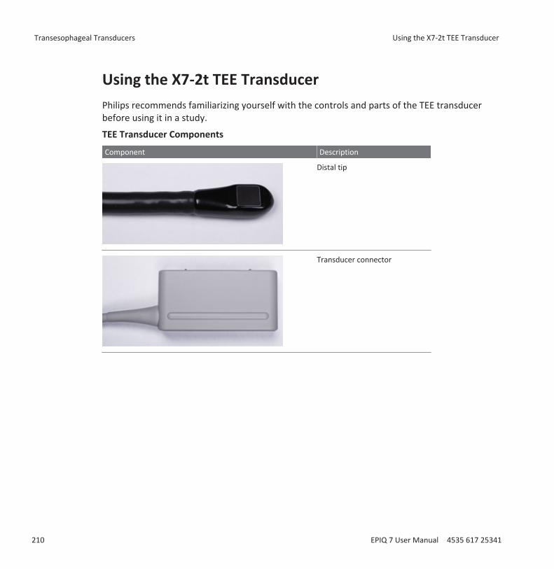
Using the X7-2t TEE TransducerPhilips recommends familiarizing yourself with the controls and parts of the TEE transducerbefore using it in a study.
TEE Transducer Components
Component Description
Distal tip
Transducer connector
Transesophageal Transducers Using the X7-2t TEE Transducer
210 EPIQ 7 User Manual 4535 617 25341
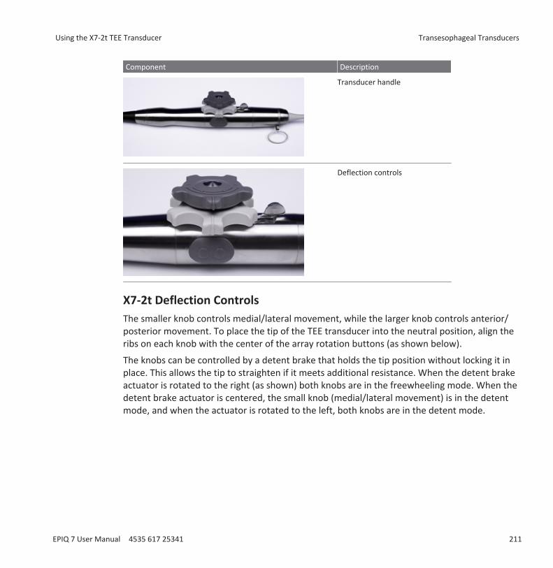
Component Description
Transducer handle
Deflection controls
X7-2t Deflection ControlsThe smaller knob controls medial/lateral movement, while the larger knob controls anterior/posterior movement. To place the tip of the TEE transducer into the neutral position, align theribs on each knob with the center of the array rotation buttons (as shown below).
The knobs can be controlled by a detent brake that holds the tip position without locking it inplace. This allows the tip to straighten if it meets additional resistance. When the detent brakeactuator is rotated to the right (as shown) both knobs are in the freewheeling mode. When thedetent brake actuator is centered, the small knob (medial/lateral movement) is in the detentmode, and when the actuator is rotated to the left, both knobs are in the detent mode.
Using the X7-2t TEE Transducer Transesophageal Transducers
EPIQ 7 User Manual 4535 617 25341 211

X7-2t Transducer ControlsControl Description
Medial/lateral control
Anterior/posterior control
Detent brake actuator
Transesophageal Transducers Using the X7-2t TEE Transducer
212 EPIQ 7 User Manual 4535 617 25341
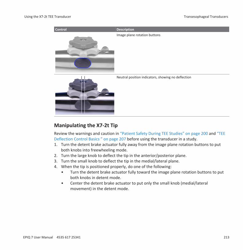
Control DescriptionImage plane rotation buttons
Neutral position indicators, showing no deflection
Manipulating the X7-2t TipReview the warnings and caution in “Patient Safety During TEE Studies” on page 200 and “TEEDeflection Control Basics ” on page 207 before using the transducer in a study.1. Turn the detent brake actuator fully away from the image plane rotation buttons to put
both knobs into freewheeling mode.2. Turn the large knob to deflect the tip in the anterior/posterior plane.3. Turn the small knob to deflect the tip in the medial/lateral plane.4. When the tip is positioned properly, do one of the following:
• Turn the detent brake actuator fully toward the image plane rotation buttons to putboth knobs in detent mode.
• Center the detent brake actuator to put only the small knob (medial/lateralmovement) in the detent mode.
Using the X7-2t TEE Transducer Transesophageal Transducers
EPIQ 7 User Manual 4535 617 25341 213
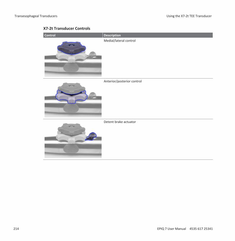
X7-2t Transducer ControlsControl Description
Medial/lateral control
Anterior/posterior control
Detent brake actuator
Transesophageal Transducers Using the X7-2t TEE Transducer
214 EPIQ 7 User Manual 4535 617 25341

Control DescriptionImage plane rotation buttons
Neutral position indicators, showing no deflection
Rotating the X7-2t Image Plane You can rotate the image plane on the X7-2t TEE transducer to achieve a 360-degree view ofthe heart. Rotation stops when you release either button.
The current degree of rotation appears in either the upper or lower part of the display,depending on image orientation. Because the center of the image array is the pivot point, youcan achieve a 360-degree view.• To rotate the X7-2t transducer image plane, do either of the following:
• To rotate the imaging plane toward the 180-degree position, press the image planerotation button that is distal to the system.
• To rotate the imaging plane toward the 0-degree position, press the button that isproximal to the system.
• To rotate the X7-2t transducer image plane using a system control, use the Seek Angle softkey.
Using the X7-2t TEE Transducer Transesophageal Transducers
EPIQ 7 User Manual 4535 617 25341 215
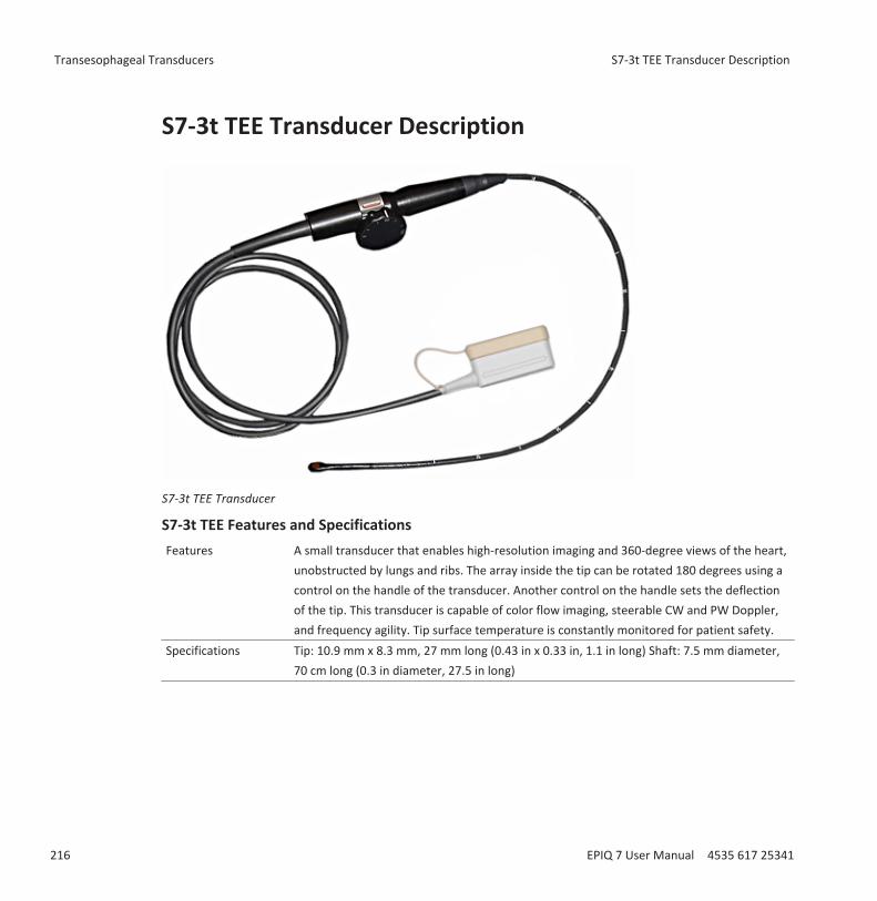
S7-3t TEE Transducer Description
S7-3t TEE Transducer
S7-3t TEE Features and SpecificationsFeatures A small transducer that enables high-resolution imaging and 360-degree views of the heart,
unobstructed by lungs and ribs. The array inside the tip can be rotated 180 degrees using acontrol on the handle of the transducer. Another control on the handle sets the deflectionof the tip. This transducer is capable of color flow imaging, steerable CW and PW Doppler,and frequency agility. Tip surface temperature is constantly monitored for patient safety.
Specifications Tip: 10.9 mm x 8.3 mm, 27 mm long (0.43 in x 0.33 in, 1.1 in long) Shaft: 7.5 mm diameter,70 cm long (0.3 in diameter, 27.5 in long)
Transesophageal Transducers S7-3t TEE Transducer Description
216 EPIQ 7 User Manual 4535 617 25341

Using the S7-3t TEE Transducer Philips recommends familiarizing yourself with the controls and parts of the TEE transducerbefore using it in an exam. For more information on transducer controls, see “S7-3t TEEControls” on page 218.
S7-3t TEE Transducer Parts
1 Distal tip2 Flexible shaft3 Transducer connector
Using the S7-3t TEE Transducer Transesophageal Transducers
EPIQ 7 User Manual 4535 617 25341 217

4 Transducer handle5 Deflection and array controls
S7-3t TEE ControlsThe transducer handle is designed for one-hand operation. Normally, you should operate thetransducer handle with your left hand. The thumb, first, and second fingers control thedeflection and the array rotation control wheels.
The smaller wheel on the transducer handle is for controlling the transducer tip deflection. Thiswheel has a locked mode and a freewheeling mode. In the locked mode, the movement of thedeflection wheel is restrained to allow you to hold the tip in a certain position. A metallic ringaround the body of the handle, which clicks on and off, controls the lock.
The larger wheel on top is for rotating the imaging array. The array can be rotated continuouslyfrom 0 degrees (transversal plane) through 90 degrees (longitudinal plane) to 180 degrees(transversal plane, left/right inverted).
WARNINGVerify that the maximum deflection of the tip is 120 degrees up and 90 degrees down. If theup/down deflection shows an unwanted amount of free play or exceeds the maximaldeflection angles, do not use the transducer. Contact Philips to readjust the steering of thetransducer. Ensuring proper deflection limits minimizes the risk of the tip folding over in theesophagus.
WARNINGTo protect the patient and the transducer, straighten the tip of the transducer and unlock thedeflection control when inserting or withdrawing the transducer. On the S7-3t, the tip isstraight when the white line on the control wheel is aligned along the shaft of the transducerhandle.
Transesophageal Transducers Using the S7-3t TEE Transducer
218 EPIQ 7 User Manual 4535 617 25341
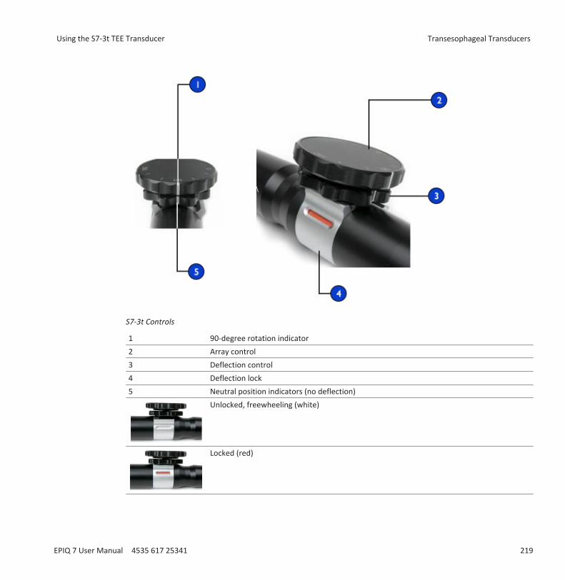
S7-3t Controls
1 90-degree rotation indicator2 Array control3 Deflection control4 Deflection lock5 Neutral position indicators (no deflection)
Unlocked, freewheeling (white)
Locked (red)
Using the S7-3t TEE Transducer Transesophageal Transducers
EPIQ 7 User Manual 4535 617 25341 219
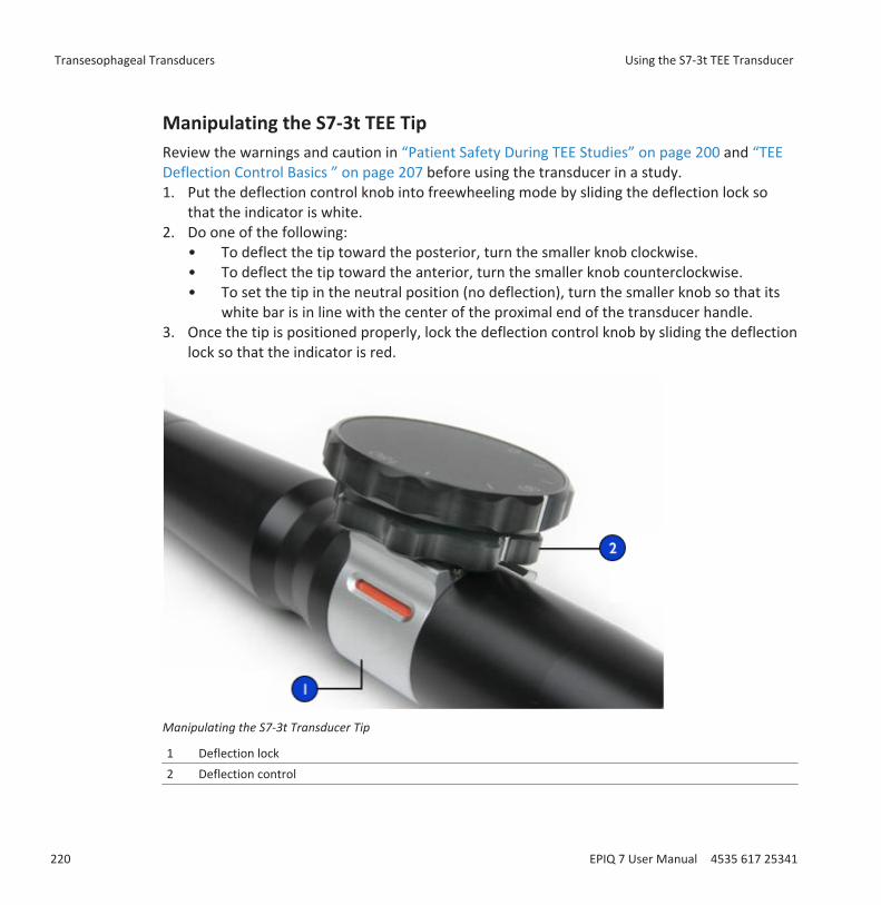
Manipulating the S7-3t TEE TipReview the warnings and caution in “Patient Safety During TEE Studies” on page 200 and “TEEDeflection Control Basics ” on page 207 before using the transducer in a study.1. Put the deflection control knob into freewheeling mode by sliding the deflection lock so
that the indicator is white.2. Do one of the following:
• To deflect the tip toward the posterior, turn the smaller knob clockwise.• To deflect the tip toward the anterior, turn the smaller knob counterclockwise.• To set the tip in the neutral position (no deflection), turn the smaller knob so that its
white bar is in line with the center of the proximal end of the transducer handle.3. Once the tip is positioned properly, lock the deflection control knob by sliding the deflection
lock so that the indicator is red.
Manipulating the S7-3t Transducer Tip
1 Deflection lock2 Deflection control
Transesophageal Transducers Using the S7-3t TEE Transducer
220 EPIQ 7 User Manual 4535 617 25341
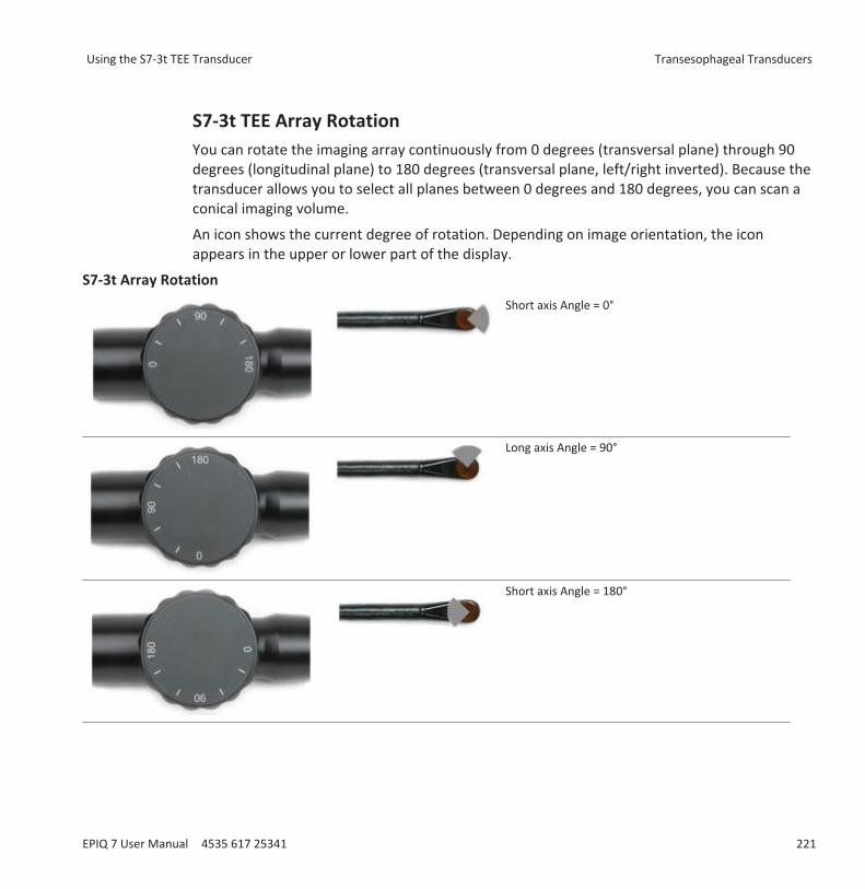
S7-3t TEE Array Rotation You can rotate the imaging array continuously from 0 degrees (transversal plane) through 90degrees (longitudinal plane) to 180 degrees (transversal plane, left/right inverted). Because thetransducer allows you to select all planes between 0 degrees and 180 degrees, you can scan aconical imaging volume.
An icon shows the current degree of rotation. Depending on image orientation, the iconappears in the upper or lower part of the display.
S7-3t Array RotationShort axis Angle = 0°
Long axis Angle = 90°
Short axis Angle = 180°
Using the S7-3t TEE Transducer Transesophageal Transducers
EPIQ 7 User Manual 4535 617 25341 221
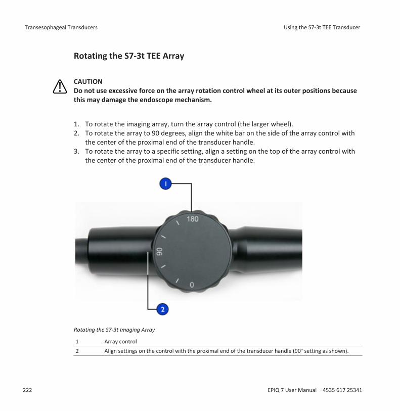
Rotating the S7-3t TEE Array
CAUTIONDo not use excessive force on the array rotation control wheel at its outer positions becausethis may damage the endoscope mechanism.
1. To rotate the imaging array, turn the array control (the larger wheel).2. To rotate the array to 90 degrees, align the white bar on the side of the array control with
the center of the proximal end of the transducer handle.3. To rotate the array to a specific setting, align a setting on the top of the array control with
the center of the proximal end of the transducer handle.
Rotating the S7-3t Imaging Array
1 Array control2 Align settings on the control with the proximal end of the transducer handle (90° setting as shown).
Transesophageal Transducers Using the S7-3t TEE Transducer
222 EPIQ 7 User Manual 4535 617 25341

Checking the TEE TransducerBefore each TEE exam, carefully inspect the transducer and try the controls, as described in thesubordinate topics.
TEE Transducer InspectionCarefully inspect the entire surface of the distal tip and flexible shaft for protrusions, holes,dents, abrasions, cuts, burrs, or cracks that could be extremely hazardous to both you and yourpatient.
Carefully feel the tip and shaft, and inspect the entire transducer. If you suspect an electricalproblem, follow the electrical safety check procedure described in "Electrical Safety Check forTEE Transducers" in the "Transesophageal Transducers" section of the User Manual.
Also check for excessive flexibility in the tip, particularly in the medial/lateral direction. Do notuse the transducer if the tip is extremely flexible. If you have any questions about tip flexibility,contact your Philips service representative.
TEE Transducer Controls InspectionUse the deflection controls to position the tip in every possible direction, both to ensure thatthe controls work properly and to get used to the feel of the TEE transducer. Make sure thatthe controls operate smoothly without binding, and that you can achieve all possible positionseasily before introducing the TEE transducer into the patient.
Test the detent brakes and freewheeling mode. Remember that the controls must be infreewheeling mode (no deflection and no brake resistance) when repositioning or withdrawingthe transducer, as well as whenever you are not imaging. See “Manipulating the X7-2t Tip” onpage 213 and “Manipulating the S7-3t TEE Tip” on page 220
Special Considerations for TEE StudiesSpecial considerations regarding TEE studies are advisable for patients with existinggastroesophageal abnormalities, such as esophageal varices, hiatal hernia, tumor, diverticula,esophageal webs and rings, fistulae, or peptic ulcers, as well as for patients who have had anti-reflux procedures. In addition, you should do the following:• Consider the patient’s size and ability to accommodate the transducer tip and shaft.
Checking the TEE Transducer Transesophageal Transducers
EPIQ 7 User Manual 4535 617 25341 223
• Check the patient’s history for gastroesophageal disease or difficulty swallowing.• Evaluate the potential overall effects of any treatment that the patient is undergoing, such
as mediastinal radiation, chemotherapy, anticoagulation, or steroid therapy.• Be aware that you may discover unsuspected esophageal pathology during a study. Be alert
for congenital problems with the esophagus or stomach, particularly with pediatric patients.• When examining a patient with an above-normal temperature, use the Auto-Cool feature
and enter the patient temperature. The Auto-Cool feature is described in “TEE TemperatureSensing” on page 228.
This list is not comprehensive. Rather, it suggests areas to investigate when considering TEE fora particular patient.
Patient Selection for TEE Transducer UseAlthough the TEE transducers can provide clinical data not available from other instruments,you should consider which patients can safely use the TEE transducers.
WARNINGThe ability of a patient to swallow or accommodate the transducer should be considered.
WARNINGYou must consider any history of gastroesophageal diseases as well as the possible effects ofother therapies that the patient is undergoing. You must also consider all gastroesophagealabnormalities or difficulty swallowing.
The following table lists the minimum patient weight recommendations when using TEEtransducers.
TEE Transducer Minimum Patient Weight RecommendationsTEE Transducer Minimum Patient WeightS7-3t 3.5 kg (7.7 lb)X7-2t 30 kg (66 lb)
Transesophageal Transducers Special Considerations for TEE Studies
224 EPIQ 7 User Manual 4535 617 25341

Preparing Patients for TEE StudiesThese suggestions for pre-study patient preparation do not constitute an exhaustive list of allpossible factors to explore before performing transesophageal echocardiography, nor do theyimply medical protocols. Instead, they reflect basic guidelines resulting from extensiveconsultation with physicians throughout the design, development, and clinical investigationperiods of Philips TEE transducers.• Besides gathering routine background information such as current medication and allergies,
investigate any history of chronic obstructive lung disease, esophageal strictures, varices, orbleeding.
• Thoroughly explain the procedure to the patient before the study.• Inform the patient not to eat or drink for at least 6 hours before the study.• Advise the patient that he or she should not plan to drive after the study, because sedatives
are often used.• Follow institutional guidelines for obtaining patient consent for a transesophageal
echocardiography (TEE) study.• Be sure that a recent ECG, CBC, and SMA6 are available as a baselines.
TEE Study GuidelinesDuring a TEE study, an assistant can provide oral and pharyngeal suctioning of the patient andcan monitor the patient’s blood pressure and general responses. For unexpected occurrences,an emergency cart with basic life-support equipment should be ready. Throughout the study, itis important to carefully monitor the patient’s reactions and to ensure that ventilation and vitalsigns are stable.
In the operating room, do not use TEE transducers during surgical procedures requiringextreme neck flexion, such as sitting craniotomies. The following are important guidelines forTEE studies. (See “TEE Transducer References” on page 238.)• Minimize the possibility of transducer tip fold-over. This problem has occurred rarely, but
its consequences can be serious. See “Tip Fold-Over” on page 226.• Maintain a patent airway. For surgical patients, endotracheal intubation establishes a
stable, patent airway before insertion of the transducer. For patients who are awake,carefully monitor the patient’s breathing at all times.
Special Considerations for TEE Studies Transesophageal Transducers
EPIQ 7 User Manual 4535 617 25341 225
• Minimize the possibility of pressure necrosis (tissue death). Do not let the distal tip displaceany one segment of tissue for more than 5 consecutive minutes. Also make sure thedeflection area and the distal tip are in the position of least potential pressure. Be sure thatthe transducer is in a freewheeling mode and unplugged whenever you are not imaging.
• Prevent potential esophageal damage. Philips recommends that you stop TEE scanning andunplug the transducer from the system during periods of poor perfusion, circulatory arrest,or the hypothermic phase of open heart surgery. To discontinue scanning, unlock thetransducer connector.
• Before each TEE study, carefully inspect the transducer, as described in “Checking the TEETransducer” on page 223. A thorough inspection procedure is required for the safety of thepatient and yourself, and to ensure the continued correct functioning of the transducer.
• Never use excessive force when inserting, operating, or withdrawing a transducer, andmake sure the deflection area is straight during insertion and withdrawal. Forcefulinsertion, manipulation, or withdrawal of a transducer can result in lacerations, bleeding,perforation, tearing of adhesions, and ligament damage. Also be aware that the tip can foldover, causing similar damage.
• Refrain from handling the distal tip whenever possible. If you must handle the distal tip,grasp it on the sides. Do not touch the top or bottom. Support the transducer’s proximalhead, either by having an assistant hold the steering mechanism or by clamping thetransducer at the steering mechanism. Ensure that the clamp does not interfere withsteering, and do not clamp any part of the flexible shaft, as this will damage the transducer.
Tip Fold-OverOn rare occasions, the tip of a TEE transducer has folded over during insertion. The effects canbe serious if the situation is handled incorrectly. The esophagus can be scraped, perforated, orotherwise damaged.
Recognizing Tip Fold-OverThe TEE transducer tip might be folded over in the patient if you encounter any of thefollowing:• Resistance to advancing or removing the transducer• An inability to turn the control knobs• Fixation of the control knobs in the maximum flexion position• Extreme difficulty in obtaining an image
Transesophageal Transducers Tip Fold-Over
226 EPIQ 7 User Manual 4535 617 25341
Correcting Tip Fold-OverIf you suspect the transducer tip is folded over, Philips' physician consultants recommend thatyou gently try to manipulate the transducer. If the tip is neither locked nor jammed in adoubled-over position, and you can move it forward, advance the transducer into the stomach.Then straighten the tip and remove the transducer.
If you cannot move the tip in any direction, Philips' consultants recommend that you X-ray thepatient to evaluate the situation. You might also want to involve a gastroenterologist oranesthesiologist.
Preventing Tip Fold-Over The following steps can prevent the tip from folding over. This list is not exhaustive; otherfactors can also be involved.
Using Correct Insertion Technique
You may find transducer insertion easier if you guide the transducer into the patient's mouthwith your fingers. You also may want to lock medial/lateral tip movement.
WARNINGAll patients should wear a bite guard during a TEE exam. A bite guard protects againstdangerous transducer mechanical and electrical malfunction caused by involuntary biting.Even anesthetized patients require bite guards to prevent damage to both their teeth and tothe transducer. For information on bite guards available from Philips, see “Bite Guards” onpage 233.
Avoid the following when inserting any TEE transducer into a patient:• Any excessive flexion of the transducer tip, particularly in the medial/lateral direction• Catching the tip in pharyngeal recesses• Insertion when a patient is being uncooperative or is having a convulsion or spasm
Tip Fold-Over Transesophageal Transducers
EPIQ 7 User Manual 4535 617 25341 227
Reviewing Patient Esophageal Pathology
Carefully review a patient's medical history for obstructing pathologies or anatomicalirregularities before performing a TEE exam.
Ensuring Proper Transducer Maintenance
Thoroughly examine the transducer and test the controls before each exam. Be sure to checkfor excessive flexibility in the tip. See “TEE Transducer Inspection” on page 223.
TEE Temperature SensingThe transesophageal transducers contain built-in temperature sensors near the distal tip. Thesensor monitors the transducer’s temperature to prevent potential burning of esophagealtissue. The patient’s actual temperature is required to accurately estimate the distal tiptemperature. By default the system assumes that the patient temperature is 37°C (98.6°F). Youmust manually enter the actual patient temperature if it is above 37°C (98.6°F).
The Auto-Cool feature provides warning messages at two points:• At 41.0°C (105.8°F), the TEE Auto Cool Imminent message appears.• At 42.5°C (108.5°F), the TEE Auto Cool In Progress message appears, and the system
automatically stops scanning.
WARNINGIf the patient temperature is above 37°C (98.6°F) and the Patient Temp control is set belowthe actual patient temperature, then the system can overestimate the temperature of theTEE transducer's distal tip. This can prematurely trigger the Auto-Cool feature. If the patienttemperature is at or near 37°C (98.6°F) and the Patient Temp control is set above the actualpatient temperature, then the system can underestimate the temperature of the distal tip.This can expose patients to excessive temperatures.
Transesophageal Transducers TEE Temperature Sensing
228 EPIQ 7 User Manual 4535 617 25341

Ensuring Safe TEE TemperaturesTo ensure patient safety and to avoid unnecessary interruption while scanning, follow thesesuggestions:• Ensure distal-tip-temperature accuracy by entering an accurate patient core temperature.• Decrease the transducer temperature by using the Output Power knob before introducing a
TEE transducer to decrease acoustic output, and keep the control at the lowest possiblesetting during an exam.
• Use the TEE Manual Auto-Cool safety feature to enter the patient temperature if it is above37°C (98.6°F) as described in “Entering Patient Temperature” on page 231.
• If the transducer temperature begins to rise when you are using high-power modes such asLive 3D, Color, Tissue Harmonic Imaging, and Doppler, temporarily switching tofundamental 2D mode or freezing the image can help cool the transducer.
Manual Auto-Cool FeatureUse the TEE Manual Auto-Cool safety feature to enter above-normal patient temperatures.When the temperature display is enabled, you can see both the patient temperature and thedistal tip temperature while scanning.
NOTEThe patient temperature shown on the ultrasound display is always either 37°C (98.6°F) or thetemperature that you manually enter. The system does not monitor or report the actual patienttemperature.
If the distal tip temperature reaches 41°C (105.8°F), a warning message appears and thetransducer temperature is displayed in inverse video. If the temperature reaches 42.5°C(108.5°F), a warning appears with the patient and the transducer temperatures, and the systemstops imaging until the distal tip cools to below 42°C (107.6°F). The system shuts down if thepatient-applied part temperature of the TEE transducer exceeds 42.5°C (108.5°F), given anentered patient temperature of 37°C (98.6°F). It resumes scanning when the temperature fallsbelow 42°C (107.6°F) . If the patient temperature is higher than 37°C (98.6°F), the systemshutdown temperature adjusts accordingly. You may need to restart the system by turning iton.
TEE Temperature Sensing Transesophageal Transducers
EPIQ 7 User Manual 4535 617 25341 229

WARNINGTo avoid the risk of esophageal burn for adult patients, minimize the time spent imaging atdistal tip temperatures in excess of 42°C (107.6°F). Exposure should be limited to 10 minutesor less at 42°C (107.6°F) or higher.
WARNINGSufficient data on thermal tolerance of the esophagus in neonate and pediatric patients doesnot exist, but it is likely these patients are more vulnerable than adults. Minimize the timespent imaging at distal tip temperatures in excess of 41°C (105.8°F).
Using the Temperature Display Both the patient temperature (assumed or entered) and the transducer temperature appear inthe lower left corner of the display when enabled. On the display, the patient temperature islabeled PAT T, and the transducer temperature is labeled TEE T.
A less-than sign (<) after TEE T indicates that the transducer's distal tip temperature is belowthe patient temperature (PAT T) assumed by the system, which is either 37°C (98.6°F) or thetemperature you entered.
NOTEIf you want the temperature display enabled by default, turn on the temperature display andthen create a preset as described in “Creating Quick Save Presets” on page 149.
1. Connect the transducer and select a preset.2. Swipe to the second touch screen.3. Touch Temp Display to display or hide the temperature display.4. Touch Temp Units to switch the temperature scale between Fahrenheit and Celsius.
Transesophageal Transducers TEE Temperature Sensing
230 EPIQ 7 User Manual 4535 617 25341

Patient TemperatureEntering a patient’s temperature enables the Auto-Cool feature to calculate tip temperaturemore accurately, which can prevent unnecessary interruptions while scanning. If a patient’stemperature is above normal, entering a temperature can avoid exposing the patient toexcessive temperatures.
Always check the patient’s temperature before inserting a TEE transducer. If it is above normal,whether from fever or therapeutic heating from a cardiac bypass heart-lung machine, performthe procedure in “Entering Patient Temperature” on page 231 before inserting the transducer.Also, follow that procedure if a patient’s temperature rises during a study.
Measure the patient’s core temperature, or more specifically, the actual temperature in theesophagus. For patients undergoing surgery, determine the temperature in the esophagus bydirect measurement or by monitoring the temperature of blood returning from the bypasspump heat exchanger.
For closed-chest situations, rectal temperature is the best estimate of core temperature. Youcan also use oral temperatures, even though they can be one degree lower than the coretemperature. If you measure an auxiliary temperature, which can be two degrees lower thanthe core temperature, add one or two degrees.
Entering Patient Temperature1. If necessary, select the TEE transducer.2. Turn Pat Temp to enter the patient's measured temperature.
NOTEEach time you turn off or reset the system, or enter a new patient ID, the system assumes thatthe patient temperature is 37°C (98.6°F).
Resuming Imaging After Auto-CoolIf the distal tip temperature drops below 42.5°C (108.5°F), the system resumes imaging. If theAuto-Cool message persists longer than 1 minute or an error message appears, contact yourPhilips service representative.
TEE Temperature Sensing Transesophageal Transducers
EPIQ 7 User Manual 4535 617 25341 231
The system shuts down if the patient-applied part temperature of the TEE transducer exceeds42.5°C (108.5°F), given an entered patient temperature of 37°C (98.6°F). If the patienttemperature is higher than 37°C (98.6°F), the system shutdown temperature adjusts
accordingly. You may need to restart the system by pressing the (On/Off) control .
WARNINGThe Reconnect the Transducer error message is often caused by a poorly seated transducerconnector, but it could be caused by a failure in the Auto-Cool safety logic. In the case of alogic failure, distal tip temperatures could reach 46.5°C (115.7°F) in hyperthermic patients(40°C to 41°C or 104°F to 106°F) before the error causes scanning to stop. At this temperature,esophageal burns may occur (see “TEE Transducer References” on page 238).
1. Move the locking lever to the unlocked position, and pull the connector out of thereceptacle.
2. Reseat the connector in the receptacle and move the locking lever to the locked position.3. Select the transducer and preset.4. If the system does not resume imaging after the transducer has initialized, shut down the
system and then restart it.
Patient Care After a TEE StudyFollow your institutional guidelines for post-TEE studies. Additionally, you might want toinclude the following recommendations in your guidelines as part of your post-TEE studyroutine.• Inspect the patient’s throat for any bleeding.• Examine the patient for postural hypotension or difficulty walking.• Instruct the patient to contact you immediately if he or she experiences any fever, chills,
chest pain, or bleeding.• Instruct the patient not to eat or drink for at least 2 hours or until swallowing returns to
normal after anesthesia has worn off. It is especially important that the patient not ingesthot foods or fluids during this period.
• Follow up with a call to the patient the day after the a study to make sure there are nocomplications.
Transesophageal Transducers Patient Care After a TEE Study
232 EPIQ 7 User Manual 4535 617 25341

TEE Accessories and SuppliesEach TEE transducer comes with disposable bite guards and a disposable tip protector. Biteguards, TEE transducer covers, tip protectors, and disposable drapes are described here. Forinformation on ordering TEE accessories, see “Supplies and Accessories” on page 21.
Bite Guards
WARNINGThe M2203A bite guard strap contains natural rubber latex, which may cause allergicreactions. For more information, see “FDA Medical Alert on Latex” on page 49.
CAUTIONDamage caused when patients bite or scrape a TEE transducer is not covered in thetransducer warranty or your service contract. Use bite guards to help prevent such accidents.
All patients must wear a bite guard during a TEE study. A bite guard prevents dangeroustransducer mechanical and electrical malfunctions caused by involuntary biting. Evenanesthetized patients require bite guards to prevent damage to their teeth and to thetransducer. Philips supplies disposable bite guards that are suitable for both awake andanesthetized patients.
TEE Transducer Covers
WARNINGTransducer covers often contain natural rubber latex and talc, which may cause allergicreactions. For more information, see “FDA Medical Alert on Latex” on page 49.
Philips recommends the use of a market-approved transducer cover during every TEE study.
TEE Accessories and Supplies Transesophageal Transducers
EPIQ 7 User Manual 4535 617 25341 233
For procedures on using transducer covers (protective sheaths), see the instructions providedwith the covers.
Tip ProtectorsWhen not using a carrying case to transport a TEE transducer, use a tip protector on its distaltip. The tip protector helps prevent serious damage to the transducer lens. Philips supplies tipprotectors designed for each of its TEE transducers.
Disposable DrapesDuring studies in which you believe contamination of the imaging system can occur, Philipsrecommends that you take universal precautions and cover the system with a disposable drape.Consult your hospital’s rules regarding equipment use in the presence of infectious disease.
TEE Leakage Current TestThe electrical safety check described here should be performed regularly to determine if thereis a hole in a transducer’s outer insulating layer. This procedure detects liquid pathways to theinterior parts of the transducer shaft and tip by measuring third-wire leakage current. Thisprocedure can be performed with any commercially available safety analyzer that is designedfor hospital use.
WARNINGOnly a technically qualified person should perform the leakage-test procedure.
TEE Test BackgroundThe test procedure (see figure) involves making an AC measurement of the ultrasound systemcurrent without a transducer. The results are then compared with the current measured whenit is forced to flow through the insulating layer of the TEE transducer. If the two currents arenearly the same, it means there is a hole in the transducer’s outer insulating layer that must befixed before using the transducer.
Transesophageal Transducers TEE Accessories and Supplies
234 EPIQ 7 User Manual 4535 617 25341

Electrical Safety Check for TEE Transducers
TEE Leakage Current Test
Symbol Definition
C Stray capacitance from the ultrasound system power wiring to the system groundedmetal chassis (1 to 3 MΩ reactance)
Z Impedance between the metal parts of the TEE transducer and a test electrodeplaced in the bucket of saline solution (about 850 kΩ with an intact outer insulatinglayer, 500 Ω with a hole in the layer)
A Microammeter to measure third-wire current, either directly from the chassis orthrough Z to the test electrode
e Line power source, either 110 Vac or 220 Vac
I Current caused by e and stray capacitance, and optionally Z
TEE Leakage Current Test Transesophageal Transducers
EPIQ 7 User Manual 4535 617 25341 235

Symbol Definition
S1 Open earth lift ground switch
S2 Line polarity switch
S3 Microammeter switch
L Line mains supply
N Neutral mains supply
E Earth ground
Current I, driven by line supply e, flows through all stray capacitances between the primarywiring and the ultrasound system’s metal chassis. Ordinarily, current then flows from the metalchassis through S3 and back to e through a third-wire ground. When S3 is thrown in the otherposition, current I is forced:• From the chassis through the metal parts of the transducer• Through impedance Z, produced by the insulating layer that covers the metal parts of the
transducer and the saline solution• Through the test electrode
Saline generally presents an impedance of about 500 Ω, so Z will vary between 850 kΩ and500 Ω, depending on whether or not there is a conductive pathway caused by a hole in thetransducer’s insulating layer.
CAUTIONDo not make a DC measurement of impedance. This could set up a voltaic cell, with the metalof the transducer and a test electrode in the salt bath forming the two electrodes and anelectrolyte. Such a voltaic cell produces inaccurate resistance measurements.
You need the following equipment to perform the electrical safety check procedure:• Dempsey 432HD or 232D safety analyzer or equivalent• Philips 21110A Disinfection Basin or equivalent• Saline solution, 9 grams (0.3 oz) of salt to 1 liter (1 qt) of tap water, or one of the tested
disinfectants listed in the “Transducer Care” section.
Transesophageal Transducers TEE Leakage Current Test
236 EPIQ 7 User Manual 4535 617 25341
Testing TEE Transducer Leakage CurrentFor a list of the equipment needed to perform the electrical safety test procedure, see “TEETest Background” on page 234.
WARNINGOnly a technically qualified person should perform this procedure.
1. Gather the equipment in the preceding list.2. Fill the basin to the fill line with saline solution.3. Place the distal tip and shaft of the transducer into the basin.4. Connect the transducer to the system.5. Plug the ultrasound system’s power cord into the test receptacle on the safety analyzer.6. Attach a lead from the safety analyzer binding post labeled RL to a metal plate submerged
in the basin.7. On the safety analyzer, set the Leads switch to RL. Set the Line Polarity switch (S2) to
NORMAL.8. Turn on the safety analyzer and the ultrasound system.9. Set the Mode switch (S3) on the safety analyzer to the Case Leakage - Ground Conductor
position. Press the Lift Ground switch (S1) on the safety analyzer and record the chassisleakage current.
10. Set the Mode switch (S3) on the safety analyzer to the ECG position. Press the Lift Groundswitch (S1) on the safety analyzer and record the patient leakage current.
The transducer fails the test if the patient leakage current recorded in step 10 is greater than80% of the chassis leakage current recorded in step 9.
This failure indicates that there is a hole in the insulating layer of the TEE shaft. A hole enables aconductive pathway to internal metal parts of the transducer and presents a potentiallyhazardous condition to a patient undergoing external defibrillation or electrosurgery. A holealso allows invasion of organic material, making it difficult to completely disinfect all portions ofthe transducer. For these reasons, the transducer must be repaired before it is used.
TEE Leakage Current Test Transesophageal Transducers
EPIQ 7 User Manual 4535 617 25341 237
TEE Transducer ReferencesCucchiara, R.F., et al. "Air Embolism in Upright Neurosurgical Patients: Detection andLocalization by Two-dimensional Transesophageal Echocardiography." Anesthesiology, 353-355,1984.
Gussenhoven, Elma, et al. "Transesophageal Two-dimensional Echocardiography: Its Role inSolving Clinical Problems." Journal of the American College of Cardiology, 975-979, 1986.
Radwin, Martin, et al. "Transesophageal Echocardiography: Intubation Techniques." PhilipsApplication Note 5091-2804E, 1992.
Urbanowitz, John H., et al. "Transesophageal Echocardiography and Its Potential for EsophagealDamage." Anesthesiology, Vol. 72, No. 1, 1990.
Transesophageal Transducers TEE Transducer References
238 EPIQ 7 User Manual 4535 617 25341

Endocavity TransducersEndocavity transducers provide high-resolution endocavity imaging for obstetric and GYNapplications. The system supports the C10-3v and the C10-4ec endocavity transducers.
WARNINGAll endocavity transducers are designed to be defibrillator safe in accordance with IEC60601-1. Nevertheless, always remove the transducer from the patient before defibrillation.
Operators of Endocavity TransducersPhilips endocavity transducers are designed for use under the guidance of physicians who areproperly trained in endocavity ultrasound imaging techniques, according to currently approvedrelevant medical practices. Philips recommends that physicians operating any Philipsendocavity transducer have the following qualifications:• Proficiency in recognizing and interpreting imaging patterns• Thorough familiarity with the safe operation, care, and maintenance of the system and
endocavity transducers• Thorough familiarity with the latest endocavity methods through literature and seminars
Patient Safety During Endocavity StudiesTo operate an endocavity transducer, you must be under the guidance of a physician who isproperly trained in endocavity ultrasound imaging techniques, according to currently approvedrelevant medical practices. You also must be thoroughly familiar with the safe operation, care,and maintenance of the ultrasound system used with the transducer, as well as proficient atinterpreting the images generated.
To help ensure patient safety when using an endocavity transducer, observe the followingguidelines:• Scrutinize the entire transducer before each use.• Operate the transducer properly.
11
Operators of Endocavity Transducers Endocavity Transducers
EPIQ 7 User Manual 4535 617 25341 239
• Do not allow water or other liquids to drip onto the transducer connector, the interior ofthe system, or the keyboard.
• Use sterile ultrasound transmission gel when performing all endocavity studies.• Protective covers are recommended for endocavity procedures; the protective covers are
mandatory in China and Japan.
WARNINGAll endocavity transducers are designed to be defibrillator safe in accordance with IEC60601-1. Nevertheless, always remove the transducer from the patient before defibrillation.
Preparing Transducers for Endocavity Use1. Place 20 cc of sterile gel or saline into the transducer cover.2. Carefully inspect each transducer cover before use, and discard it if you find tears or
blemishes. Also inspect each transducer cover after use. If you find a tear, the patient or thetransducer may have been contaminated.
3. Insert the transducer into the transducer cover and unfurl the transducer cover until itcovers the transducer and its cable. The cover must be unfurled far enough to maintain thesterile field.
4. Use a sterile elastic band or clip to hold the proximal end of the transducer cover in place.5. Ensure that wrinkles and bubbles over the face of the transducer are minimized. Check the
transducer cover for tears or damage before proceeding.6. When operating the transducer, make sure that proper orientation is maintained to avoid
interpretation confusion.
NOTETo achieve good acoustic contact, make sure that the imaging surface is moist.
NOTEImaging improves with adequate coupling between the patient surface and the transducer-cover surface. Sterile water is a good acoustic-coupling agent during surgery.
Endocavity Transducers Preparing Transducers for Endocavity Use
240 EPIQ 7 User Manual 4535 617 25341
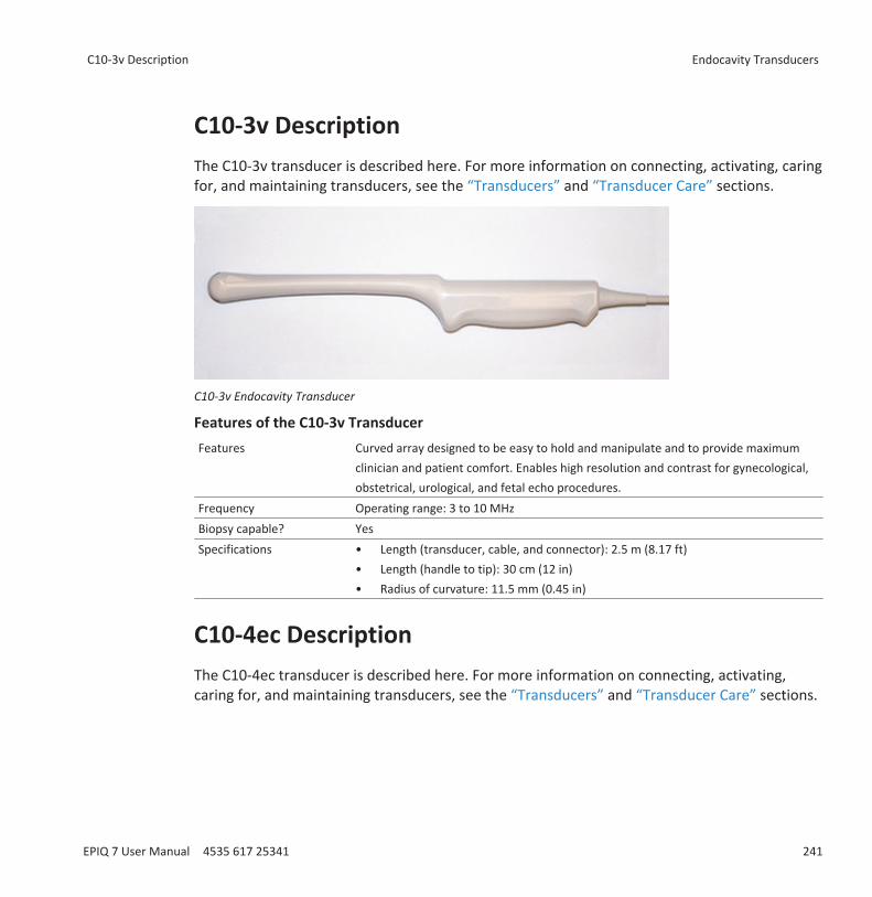
C10-3v DescriptionThe C10-3v transducer is described here. For more information on connecting, activating, caringfor, and maintaining transducers, see the “Transducers” and “Transducer Care” sections.
C10-3v Endocavity Transducer
Features of the C10-3v TransducerFeatures Curved array designed to be easy to hold and manipulate and to provide maximum
clinician and patient comfort. Enables high resolution and contrast for gynecological,obstetrical, urological, and fetal echo procedures.
Frequency Operating range: 3 to 10 MHzBiopsy capable? YesSpecifications • Length (transducer, cable, and connector): 2.5 m (8.17 ft)
• Length (handle to tip): 30 cm (12 in)• Radius of curvature: 11.5 mm (0.45 in)
C10-4ec DescriptionThe C10-4ec transducer is described here. For more information on connecting, activating,caring for, and maintaining transducers, see the “Transducers” and “Transducer Care” sections.
C10-3v Description Endocavity Transducers
EPIQ 7 User Manual 4535 617 25341 241
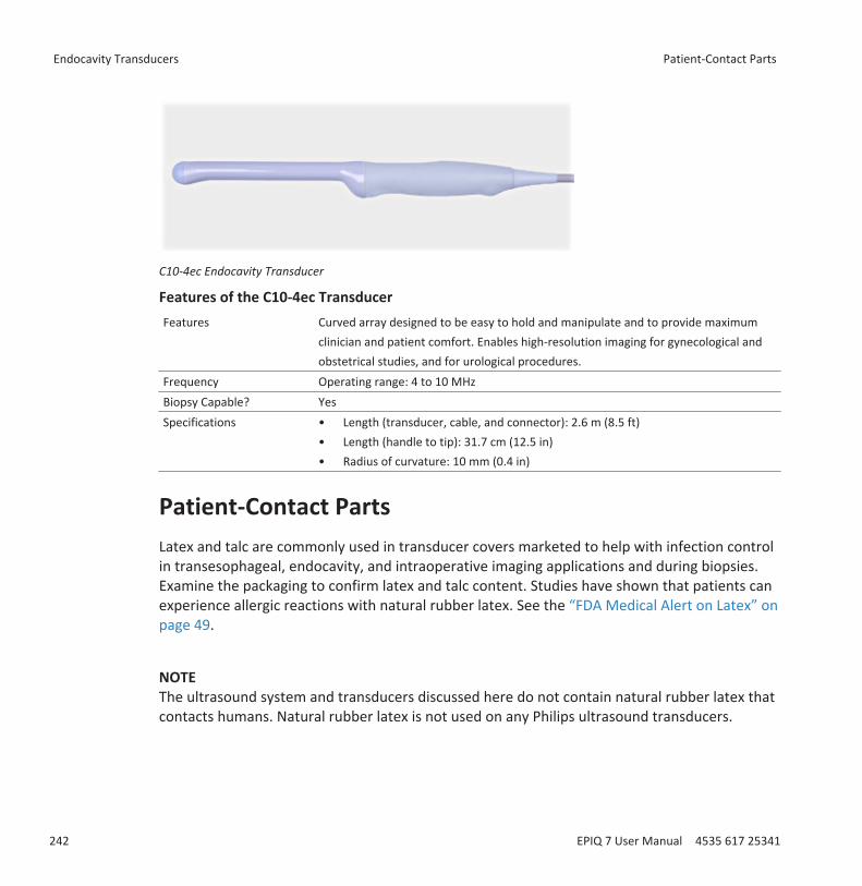
C10-4ec Endocavity Transducer
Features of the C10-4ec TransducerFeatures Curved array designed to be easy to hold and manipulate and to provide maximum
clinician and patient comfort. Enables high-resolution imaging for gynecological andobstetrical studies, and for urological procedures.
Frequency Operating range: 4 to 10 MHzBiopsy Capable? YesSpecifications • Length (transducer, cable, and connector): 2.6 m (8.5 ft)
• Length (handle to tip): 31.7 cm (12.5 in)• Radius of curvature: 10 mm (0.4 in)
Patient-Contact PartsLatex and talc are commonly used in transducer covers marketed to help with infection controlin transesophageal, endocavity, and intraoperative imaging applications and during biopsies.Examine the packaging to confirm latex and talc content. Studies have shown that patients canexperience allergic reactions with natural rubber latex. See the “FDA Medical Alert on Latex” onpage 49.
NOTEThe ultrasound system and transducers discussed here do not contain natural rubber latex thatcontacts humans. Natural rubber latex is not used on any Philips ultrasound transducers.
Endocavity Transducers Patient-Contact Parts
242 EPIQ 7 User Manual 4535 617 25341

Biopsy with Endocavity TransducersEndocavity transducers are biopsy capable.
For more information on the biopsy guide feature, see the “Biopsy Guides” section.
NOTECIVCO Medical Solutions supplies biopsy kits for Philips transducers that are biopsy capable. Forinformation on proper attachment of a biopsy bracket, consult the manufacturer’s instructions.
Biopsy with Endocavity Transducers Endocavity Transducers
EPIQ 7 User Manual 4535 617 25341 243

Endocavity Transducers Biopsy with Endocavity Transducers
244 EPIQ 7 User Manual 4535 617 25341
Biopsy GuidesThe biopsy guide feature helps you position transducers with biopsy needle-guide attachments.The biopsy guide feature displays guidelines on the image that show the anticipated path of theneedle. You can use those guidelines to ensure that the needle or instrument is following thecorrect path.
Starter kits, which include the biopsy guide or biopsy guide bracket and procedure kits, areavailable from Philips. Biopsy guides and supplies are available from CIVCO Medical Solutions(see “Supplies and Accessories” on page 21).
For detailed information about using, cleaning, and sterilizing biopsy guides and brackets, seethe instructions provided with the biopsy starter kits, guides, and brackets.
NOTEThe biopsy guides for the L12-5 50 mm, and L18-5 transducers have infinite-angle capability andcan be installed on either side of the transducer; they do not constrain the biopsy needle to aparticular path. Because the needle path is unpredictable, the Biopsy control is unavailable, andthe biopsy graphics do not appear on the display when you are using these transducers. Abiopsy with these transducers is a manual action. The C5-1 and the C9-2 also support infinite-angle biopsy guides but the graphics should not be used.
Attaching and Removing a Biopsy GuideDetailed information about attachment and removal of biopsy guides is provided with thebiopsy starter kits, guides, and brackets.
WARNINGDo not attempt to use the biopsy guide until you have read the instructions for selecting thedisplay, installing the sterile transducer cover, and verifying alignment of the biopsy guide.
12
Attaching and Removing a Biopsy Guide Biopsy Guides
EPIQ 7 User Manual 4535 617 25341 245
WARNINGInspect all components and the transducer. Ensure that the biopsy guide you are using is thecorrect one for the transducer, the system, and system software. Your Philips representativecan verify this information for you.
WARNINGUse only Philips-approved biopsy guides, transducers, covers, brackets, supplies,components, and accessories. Other brands may not properly fit Philips transducers.Improper installation may result in patient injury.
WARNINGSome biopsy guides must be installed over a sterile transducer cover.
WARNINGAfter each use, biopsy guides must be either sterilized or disposed of, depending upon thetype. See the instructions included with the biopsy guide.
WARNINGMost transducers can only be disinfected; they cannot be sterilized. Only the transducercover provides the sterile barrier.
Biopsy Guideline Display
WARNINGDo not attempt to use the biopsy guide until you have read the instructions for selecting thedisplay, installing the sterile transducer cover, and verifying alignment of the biopsy guide.
Biopsy Guides Biopsy Guideline Display
246 EPIQ 7 User Manual 4535 617 25341
The system generates a biopsy guideline through the displayed real-time ultrasound image toindicate the anticipated path of the needle. You can use that guideline to ensure that theneedle or instrument is following the correct path.
When the biopsy display is active, a biopsy guideline is displayed, entering from the left or rightside of the screen, depending on the clinical application and image presentation you haveselected. When you reverse the image presentation by touching Left/Right, the biopsyguideline moves to the opposite side. Image presentation is defined by the location of theorientation marker.
When depth is changed, the biopsy display redraws to reflect the new relationships at the newdepth setting.
Displaying the Biopsy Guideline
WARNINGWhen using a transducer with an infinite-angle biopsy guide, do not display a fixed-anglebiopsy guideline.
The biopsy guideline can have a single, fixed path or multiple paths. The system determineswhich guideline to display based on the type of biopsy guide available for the transducer youhave selected.
NOTEThe following procedure applies specifically to non-intervention applications.
1. Connect the transducer.2. Touch a preset.3. Touch the 2D tab.4. Touch Biopsy.
Displaying the Biopsy Guideline Biopsy Guides
EPIQ 7 User Manual 4535 617 25341 247
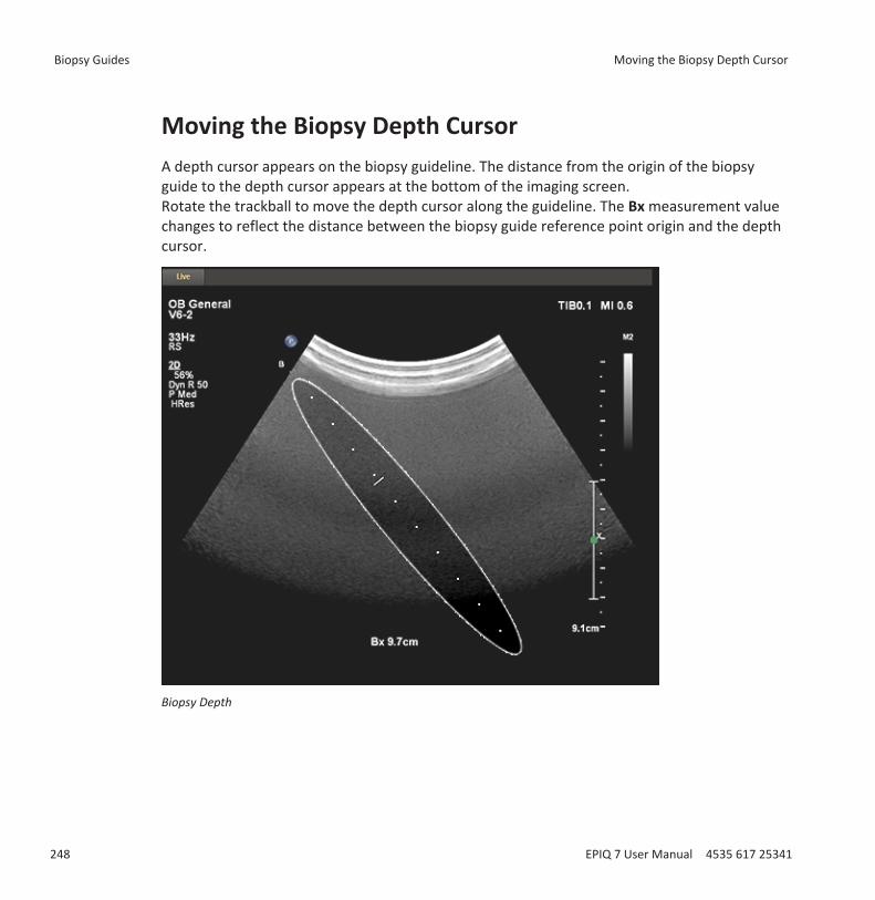
Moving the Biopsy Depth CursorA depth cursor appears on the biopsy guideline. The distance from the origin of the biopsyguide to the depth cursor appears at the bottom of the imaging screen.Rotate the trackball to move the depth cursor along the guideline. The Bx measurement valuechanges to reflect the distance between the biopsy guide reference point origin and the depthcursor.
Biopsy Depth
Biopsy Guides Moving the Biopsy Depth Cursor
248 EPIQ 7 User Manual 4535 617 25341
Biopsy Guide AlignmentPerform the alignment verification before each use of the biopsy guide. The procedure verifiesthe system, transducer, and biopsy guide relationships.
WARNINGAlignment verification is necessary before performing procedures with the biopsy guide.
WARNINGDo not use the biopsy guide if the needle is not following the intended path. Contact yourPhilips representative.
WARNINGThe needle used for this alignment verification must not be used for the actual procedure.Always use a new, sterile needle for each biopsy procedure.
WARNINGTo assist in an accurate projection of the needle, use a straight, new needle for eachalignment procedure.
Preparation for Alignment VerificationAssemble the following items before performing the alignment verification:• Transducer• Biopsy guide or bracket (The bracket is not disposable. The type of bracket you use depends
upon the transducer you are using. For the correct bracket, contact CIVCO MedicalSolutions; see “Supplies and Accessories” on page 21.)
• Needle guide (Contact CIVCO for the needle guide that fits your biopsy guide bracket.)• Sterile procedure kit (disposable)• New, straight, biopsy needle
Biopsy Guide Alignment Biopsy Guides
EPIQ 7 User Manual 4535 617 25341 249
• Beaker of water (or water bath)
Verifying the Biopsy Guide Alignment
WARNINGIf the needle enters from the unexpected side of the display or cannot be seen, verify that thebiopsy guide is correctly mounted on the transducer and that the orientation of thetransducer is correct. If the needle is still not following the expected path along the guideline,do not use the biopsy guide. Contact your Philips representative.
1. Attach the biopsy guide. Although some transducers require the use of a second transducercover for biopsy procedures, a second transducer cover is unnecessary for this alignmentverification.
2. Connect the transducer to the system, and select the appropriate applications and preset.3. Set the system depth for the procedure to be performed.4. Display the biopsy guideline.5. Without changing the position of the biopsy depth cursor, note the default depth shown at
the bottom of the display.6. Immerse the transducer no more than 6 mm (0.25 in) into the water bath.
Biopsy Guides Biopsy Guide Alignment
250 EPIQ 7 User Manual 4535 617 25341

Immersing the Transducer7. Select a new, straight needle that matches the needle-gauge size on the biopsy guide clip
you are using (if applicable), select the guide channel on the biopsy guide (A, B, and so on),and use the Biopsy soft key to select the matching biopsy angle setting.
8. Insert the straight, new needle into the biopsy guide.9. Move the needle down into the water bath until its ultrasound image is visible on the video
display.10. Verify that the needle, as seen on the video display, falls along the guideline along the
entire depth of the guideline display. The biopsy guideline is intended only to provide anindication of the expected path of the needle. Actual position must be verified byidentifying the echoes from the needle.
11. Remove the needle from the biopsy guide.12. From the tip of the needle, measure a distance equal to the value noted in step 5. Mark this
point on the needle.13. Immerse the transducer no more than 6 mm (0.25 in) into the water bath.
Biopsy Guide Alignment Biopsy Guides
EPIQ 7 User Manual 4535 617 25341 251
14. Insert the needle into a guide channel that corresponds to the size of the needle and theangle you selected. Continue sliding the needle in until the mark on the needle aligns withthe origin on the biopsy guide. (The origin is the point at which the needle enters the biopsyguide.)
15. Move the biopsy depth cursor to the tip of the needle, as seen on the display, and verifythat the displayed depth is within 4 mm (0.16 in) of the value noted in step 5.
16. Confirm that the needle is visible along its expected path. If so, then the biopsy guide isproperly aligned.
Performing a Biopsy Procedure
WARNINGBefore the biopsy procedure, perform alignment verification at the selected depth, to ensurethat the biopsy guide and the needle have been installed properly.
WARNINGUse a straight, new, sterile needle for each procedure.
WARNINGDo not perform the biopsy guide procedure if the needle is not visible
WARNINGThe biopsy guideline is intended only to provide an indication of the expected path of theneedle. Actual position must be verified by identifying the echoes from the needle.
WARNINGIf the needle is not following the expected path, discontinue the procedure and contact yourPhilips representative.
Biopsy Guides Performing a Biopsy Procedure
252 EPIQ 7 User Manual 4535 617 25341
WARNINGThin needles can bend when entering tissue. Actual position must be verified by identifyingthe echoes from the needle.
WARNINGReverberation or other tissue artifacts may produce false needle images, which can causeconfusion in locating the actual needle image. Ensure the needle path is along the guideline,and that you are not using a false needle image to locate the needle.
WARNINGWhen using a transducer with an infinite-angle biopsy guide, do not display a fixed-anglebiopsy guideline.
WARNINGPhilips does not recommend anatomical survey of the prostate with the biopsy guideattached.
1. Install the transducer cover and the biopsy guide according to the instructions providedwith the biopsy guide.
2. Select a new, straight needle that matches the needle-gauge size on the biopsy guide clipyou are using (if applicable), and select the guide channel on the biopsy guide.
3. Set the system imaging controls for the biopsy procedure.4. Touch a preset.5. Touch the 2D tab.6. Touch Biopsy.
7. Orient the transducer to match image presentation. Use the orientation marker .8. If necessary, apply sterile acoustic coupling gel to the patient.9. Begin scanning the patient. Position the transducer so that the puncture target is
intersected by the guideline on the display.10. Do one of the following:
• For guides with a single angle, insert the needle into the needle guide groove closest tothe transducer.
Performing a Biopsy Procedure Biopsy Guides
EPIQ 7 User Manual 4535 617 25341 253
• For guides with multiple angles, insert the needle into the needle guide groove thatcorresponds to the angle you previously selected.
11. Perform the puncture by sliding the needle through the groove in the guide until theneedle, as shown on the display, intercepts the target.
12. If you are using a biopsy guide bracket and procedure kit, you can remove the transducerfrom the patient while the needle is still inserted in the patient: Separate the needle fromthe biopsy guide by pulling the tab up so that the clip snaps out of the needle guide,allowing the clip (still attached to the needle) and needle to separate from the biopsy guide(still attached to the transducer).
13. Remove the biopsy guide after use.
Biopsy Guide Maintenance
WARNINGThe biopsy procedure kit components are disposable and must not be reused.
For information and instructions on cleaning, disinfecting, and sterilizing the biopsy guide, seethe instructions provided with the biopsy guide.
Biopsy Guides Biopsy Guide Maintenance
254 EPIQ 7 User Manual 4535 617 25341
Transducer CareThis section contains information on cleaning, disinfecting, and sterilizing transducers that arecompatible with your ultrasound system.
For information on the gels that are safe to use with your system's transducers, see“Ultrasound Transmission Gels” on page 184.
These instructions are intended to assist in effective cleaning, disinfection, and sterilization. Inaddition, these instructions will help avoid damage, which could void your warranty, duringcleaning, disinfection, and sterilization.
Transducer Care SafetyObserve the following warnings and cautions when using disinfectants. More specific warningsand cautions are included within the various procedures in this section and on the labels of thecleaning or disinfection solutions.
WARNINGDisinfectants listed in this manual are recommended because of their chemical compatibilitywith product materials, not their biological effectiveness. For the biological effectiveness of adisinfectant, see the guidelines and recommendations of the disinfectant manufacturer, theU.S. Food and Drug Administration, and the U.S. Centers for Disease Control.
WARNINGThe level of disinfection required for a device is dictated by the type of tissue it will contactduring use. Ensure the disinfectant type is appropriate for the type of transducer and thetransducer application. For information on the levels of disinfection requirements, see“Choosing the Correct Transducer-Care Method” on page 257. Also, see the disinfectant labelinstructions and the recommendations of the Association for Professionals in InfectionControl, the U.S. Food and Drug Administration, and the U.S. Centers for Disease Control.
13
Transducer Care Safety Transducer Care
EPIQ 7 User Manual 4535 617 25341 255
WARNINGSterile transducer covers with sterile ultrasound transmission gel are required forintraoperative and biopsy procedures, and protective covers are recommended fortransrectal and intravaginal procedures, but in China and Japan, the covers are mandatory.Philips recommends the use of qualified covers.
WARNINGBite guards are mandatory for TEE transducers. See “Bite Guards” on page 233.
WARNINGIn intraoperative applications, sterilized transducers should be used with sterile gel and asterile transducer cover.
For information on ordering transducer covers, contact CIVCO Medical Solutions (see “Suppliesand Accessories” on page 21).
Latex Product AlertPhilips ultrasound systems and transducers do not contain natural rubber latex that contactshumans. Natural rubber latex is not used on any ultrasound transducer, including transthoracic,intraoperative, and transesophageal echocardiography (TEE) transducers. It also is not used onPhilips ECG cables for the products in this manual.
WARNINGTransducer covers can contain natural rubber latex, which may cause allergic reactions insome individuals.
WARNINGThe M2203A bite guard strap contains natural rubber latex, which may cause allergicreactions.
Transducer Care Transducer Care Safety
256 EPIQ 7 User Manual 4535 617 25341

For information on allergic reactions to latex-containing medical devices, see “FDA MedicalAlert on Latex” on page 49.
Transmissible Spongiform Encephalopathy
WARNINGIf a sterile transducer cover becomes compromised during an intraoperative applicationinvolving a patient with transmissible spongiform encephalopathy, such as Creutzfeldt-Jakobdisease, follow the guidelines of the U.S. Centers for Disease Control and this document fromthe World Health Organization: WHO/CDS/ APH/2000/3, WHO Infection Control Guidelinesfor Transmissible Spongiform Encephalopathies. The transducers for your system cannot bedecontaminated using a heat process.
Choosing the Correct Transducer-Care MethodTo choose an appropriate care method for your transducer, you first must determine thetransducer's classification, based on its use.
Care Methods by Transducer TypeTransducer Use Example Classification Care MethodContacts intact skin Curved, linear, xMatrix, and
sector transducersNoncritical Low-level disinfection (see
“Transducer, Cable, and ConnectorCleaning” on page 258)
Contacts mucousmembranes
Endocavity andtransesophageal (TEE)
Semi-critical High-level disinfection (see“Transducer, Cable, and ConnectorCleaning” on page 258 and“Transducer Disinfection” on page263)
Enters otherwisesterile tissue
Intraoperative Critical Sterilization (see “Transducer, Cable,and Connector Cleaning” on page 258and “Transducer Sterilization” on page273)
Transducer Care Safety Transducer Care
EPIQ 7 User Manual 4535 617 25341 257
The care method for your transducer determines the appropriate disinfectant for yourtransducer. For details about compatible disinfectants, see “Disinfectants Compatibility” onpage 276.
Transducer, Cable, and Connector CleaningThese general cleaning (low-level disinfection) instructions are indicated for all transducers andcables. It is important that you clean the transducer and cable according to the followingprocedures.
WARNINGAlways use protective eyewear and gloves when cleaning and disinfecting any equipment.
WARNINGIf a premixed solution is used, be sure to observe the solution expiration date.
WARNINGTransducers must be cleaned after each use. Cleaning the transducer is an essential stepbefore effective disinfection or sterilization. Be sure to follow the manufacturer’s instructionswhen using disinfectants.
CAUTIONAttempting to disinfect a cable or connector by using a method other than the one includedhere can damage the device and voids the warranty.
CAUTIONDo not allow sharp objects, such as scalpels or cauterizing knives, to touch transducers orcables.
Transducer Care Transducer, Cable, and Connector Cleaning
258 EPIQ 7 User Manual 4535 617 25341
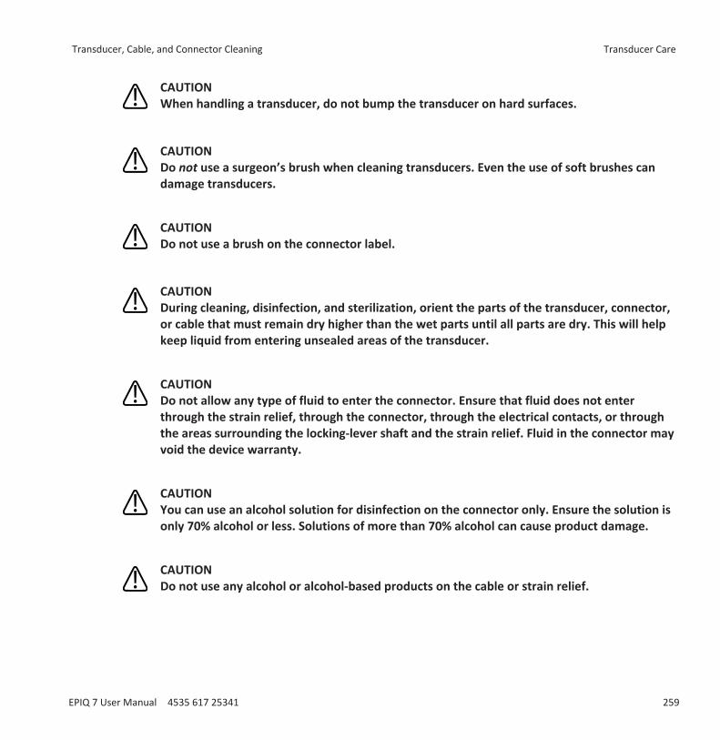
CAUTIONWhen handling a transducer, do not bump the transducer on hard surfaces.
CAUTIONDo not use a surgeon’s brush when cleaning transducers. Even the use of soft brushes candamage transducers.
CAUTIONDo not use a brush on the connector label.
CAUTIONDuring cleaning, disinfection, and sterilization, orient the parts of the transducer, connector,or cable that must remain dry higher than the wet parts until all parts are dry. This will helpkeep liquid from entering unsealed areas of the transducer.
CAUTIONDo not allow any type of fluid to enter the connector. Ensure that fluid does not enterthrough the strain relief, through the connector, through the electrical contacts, or throughthe areas surrounding the locking-lever shaft and the strain relief. Fluid in the connector mayvoid the device warranty.
CAUTIONYou can use an alcohol solution for disinfection on the connector only. Ensure the solution isonly 70% alcohol or less. Solutions of more than 70% alcohol can cause product damage.
CAUTIONDo not use any alcohol or alcohol-based products on the cable or strain relief.
Transducer, Cable, and Connector Cleaning Transducer Care
EPIQ 7 User Manual 4535 617 25341 259
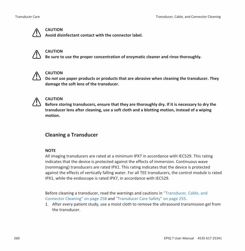
CAUTIONAvoid disinfectant contact with the connector label.
CAUTIONBe sure to use the proper concentration of enzymatic cleaner and rinse thoroughly.
CAUTIONDo not use paper products or products that are abrasive when cleaning the transducer. Theydamage the soft lens of the transducer.
CAUTIONBefore storing transducers, ensure that they are thoroughly dry. If it is necessary to dry thetransducer lens after cleaning, use a soft cloth and a blotting motion, instead of a wipingmotion.
Cleaning a Transducer
NOTEAll imaging transducers are rated at a minimum IPX7 in accordance with IEC529. This ratingindicates that the device is protected against the effects of immersion. Continuous wave(nonimaging) transducers are rated IPX1. This rating indicates that the device is protectedagainst the effects of vertically falling water. For all TEE transducers, the control module is ratedIPX1, while the endoscope is rated IPX7, in accordance with IEC529.
Before cleaning a transducer, read the warnings and cautions in “Transducer, Cable, andConnector Cleaning” on page 258 and “Transducer Care Safety” on page 255.1. After every patient study, use a moist cloth to remove the ultrasound transmission gel from
the transducer.
Transducer Care Transducer, Cable, and Connector Cleaning
260 EPIQ 7 User Manual 4535 617 25341

2. Disconnect the transducer from the system, and remove any accessories attached to orcovering the transducer.
3. To remove all organic matter and other residue, use a pre-cleaner or detergent to assist inremoving protein residuals. Enzymatic cleaners must be diluted prior to use per themanufacturer’s instructions for dilution. Enzymatic cleaners are generically approved foruse.
4. When cleaning the lens, use a blotting motion rather than a wiping motion.5. To remove remaining particulate and cleaning residue, rinse thoroughly with water up to
the immersion point shown in “Disinfecting Non-TEE Transducers by Immersion” on page268 and “Disinfecting TEE Transducers by Immersion” on page 270.
6. Optional: Wipe with a dry cloth. To dry the lens, use a soft cloth and a blotting motioninstead of a wiping motion.
NOTEIf you use cleaning wipes, it may be unnecessary to rinse the transducer with water. Alwaysfollow the product label recommendations.
Cleaning and Disinfecting Cables and ConnectorsBefore cleaning the cables and connectors, read the warnings and cautions in “Transducer,Cable, and Connector Cleaning” on page 258 and “Transducer Care Safety” on page 255.
The cables and connectors of all transducers can be disinfected using a recommended wipe orspray disinfectant.
CAUTIONDo not bend or crimp the gastroscope or cable.
1. Disconnect the device from the system.2. Push the connector cover, if available, onto the connector to protect against fluid splashing
onto the contacts.3. Orient the device and the connector so they are both facing up (strain reliefs on the
bottom).
Transducer, Cable, and Connector Cleaning Transducer Care
EPIQ 7 User Manual 4535 617 25341 261
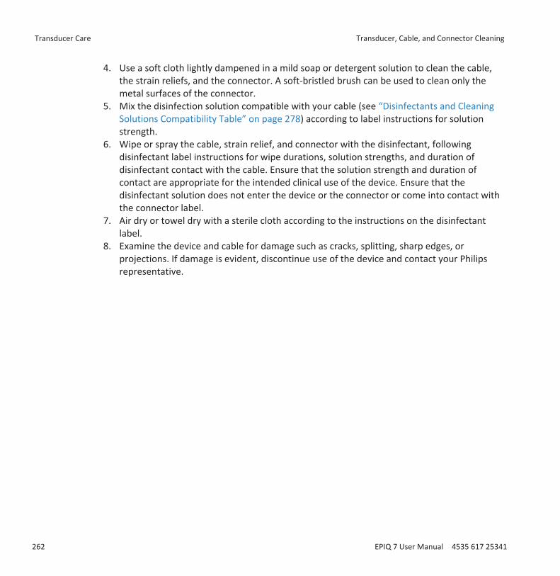
4. Use a soft cloth lightly dampened in a mild soap or detergent solution to clean the cable,the strain reliefs, and the connector. A soft-bristled brush can be used to clean only themetal surfaces of the connector.
5. Mix the disinfection solution compatible with your cable (see “Disinfectants and CleaningSolutions Compatibility Table” on page 278) according to label instructions for solutionstrength.
6. Wipe or spray the cable, strain relief, and connector with the disinfectant, followingdisinfectant label instructions for wipe durations, solution strengths, and duration ofdisinfectant contact with the cable. Ensure that the solution strength and duration ofcontact are appropriate for the intended clinical use of the device. Ensure that thedisinfectant solution does not enter the device or the connector or come into contact withthe connector label.
7. Air dry or towel dry with a sterile cloth according to the instructions on the disinfectantlabel.
8. Examine the device and cable for damage such as cracks, splitting, sharp edges, orprojections. If damage is evident, discontinue use of the device and contact your Philipsrepresentative.
Transducer Care Transducer, Cable, and Connector Cleaning
262 EPIQ 7 User Manual 4535 617 25341

Cleaning Cables and Connectors
1 Transducer strain relief2 Electrical contacts3 Connector strain relief
Transducer DisinfectionTo disinfect transducers, you can use either an immersion method or a wipe method with adisinfectant recommended by Philips Ultrasound. Use the method that is biologicallyappropriate, as described in “Choosing the Correct Transducer-Care Method” on page 257.
WARNINGAlways use protective eyewear and gloves when cleaning and disinfecting any equipment.
Transducer Disinfection Transducer Care
EPIQ 7 User Manual 4535 617 25341 263
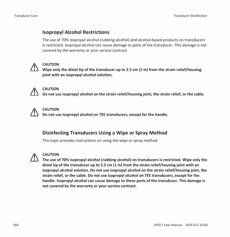
Isopropyl Alcohol RestrictionsThe use of 70% isopropyl alcohol (rubbing alcohol) and alcohol-based products on transducersis restricted. Isopropyl alcohol can cause damage to parts of the transducer. This damage is notcovered by the warranty or your service contract.
CAUTIONWipe only the distal tip of the transducer up to 2.5 cm (1 in) from the strain relief/housingjoint with an isopropyl alcohol solution.
CAUTIONDo not use isopropyl alcohol on the strain relief/housing joint, the strain relief, or the cable.
CAUTIONDo not use isopropyl alcohol on TEE transducers, except for the handle.
Disinfecting Transducers Using a Wipe or Spray Method This topic provides instructions on using the wipe or spray method.
CAUTIONThe use of 70% isopropyl alcohol (rubbing alcohol) on transducers is restricted. Wipe only thedistal tip of the transducer up to 2.5 cm (1 in) from the strain relief/housing joint with anisopropyl alcohol solution. Do not use isopropyl alcohol on the strain relief/housing joint, thestrain relief, or the cable. Do not use isopropyl alcohol on TEE transducers, except for thehandle. Isopropyl alcohol can cause damage to these parts of the transducer. This damage isnot covered by the warranty or your service contract.
Transducer Care Transducer Disinfection
264 EPIQ 7 User Manual 4535 617 25341
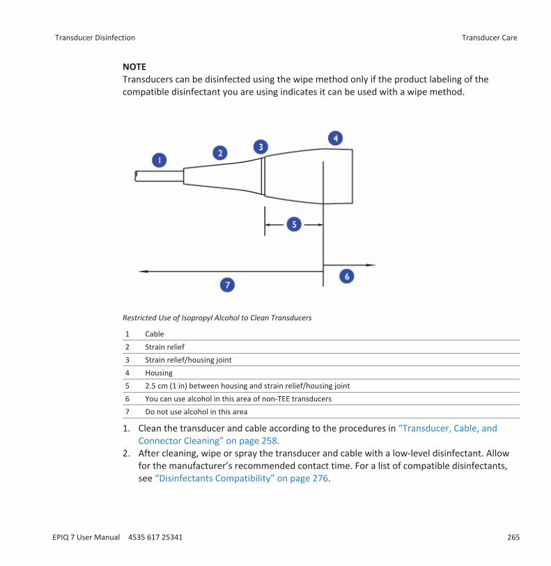
NOTETransducers can be disinfected using the wipe method only if the product labeling of thecompatible disinfectant you are using indicates it can be used with a wipe method.
Restricted Use of Isopropyl Alcohol to Clean Transducers
1 Cable2 Strain relief3 Strain relief/housing joint4 Housing5 2.5 cm (1 in) between housing and strain relief/housing joint6 You can use alcohol in this area of non-TEE transducers7 Do not use alcohol in this area
1. Clean the transducer and cable according to the procedures in “Transducer, Cable, andConnector Cleaning” on page 258.
2. After cleaning, wipe or spray the transducer and cable with a low-level disinfectant. Allowfor the manufacturer’s recommended contact time. For a list of compatible disinfectants,see “Disinfectants Compatibility” on page 276.
Transducer Disinfection Transducer Care
EPIQ 7 User Manual 4535 617 25341 265
NOTEIf you use cleaning wipes, it may be unnecessary to rinse the transducer with water. Alwaysfollow your product label recommendations.
3. Examine the device and cable for damage such as cracks, splitting, sharp edges, orprojections. If damage is evident, discontinue use of the device and contact your Philipsrepresentative.
Transducer Disinfection by ImmersionMethods for disinfecting transesophageal (TEE) and non-TEE transducers differ. Observe thefollowing warnings and cautions and then see the procedure for your transducer. For non-TEEtransducers, see “Disinfecting Non-TEE Transducers by Immersion” on page 268. For TEEtransducers, see “Disinfecting TEE Transducers by Immersion” on page 270 or “Disinfecting TEETransducers with an AER” on page 273.
WARNINGIf a premixed disinfectant is used, be sure to observe the expiration date.
NOTEAll imaging transducers are rated at a minimum IPX7 in accordance with IEC529. This ratingindicates that the device is protected against the effects of immersion. Continuous wave(nonimaging) transducers are rated IPX1. This rating indicates that the device is protectedagainst the effects of vertically falling water. For all TEE transducers, the control module is ratedIPX1, while the endoscope is rated IPX7, in accordance with IEC529.
CAUTIONUsing non-recommended disinfectants, using incorrect solution strengths, or immersing atransducer deeper or longer than recommended can damage or discolor the transducer andvoids the transducer warranty.
Transducer Care Transducer Disinfection
266 EPIQ 7 User Manual 4535 617 25341
CAUTIONDo not immerse transducers longer than the minimum time needed for your level ofdisinfection. For information on the levels of disinfection requirements, see “Choosing theCorrect Transducer-Care Method” on page 257.
Minimizing the Effects of Residual DisinfectantIf you use an OPA-based disinfectant, residual solution may remain on your transducers if youdo not carefully follow the manufacturer’s instructions.
WARNINGResidual OPA on TEE transducers may cause temporary staining of the mouth and lip areaand irritation or chemical burns of the mouth, throat, esophagus, and stomach.
To minimize the effects from residual OPA, or any other disinfectant, Philips recommends thefollowing:
WARNINGFollow the disinfectant manufacturer’s instructions very carefully. For example, themanufacturer of Cidex OPA recommends soaking transducers three times in fresh water.
WARNINGUse a protective transducer cover during endocavity and TEE studies.
WARNINGUse a sterile protective transducer cover with sterile ultrasound transmission gel duringintraoperative and biopsy studies.
Transducer Disinfection Transducer Care
EPIQ 7 User Manual 4535 617 25341 267
WARNINGLimit the time that transducers are soaked in the disinfectant solution to the minimum timerecommended by the disinfectant manufacturer (for example, the manufacturer of Cidex OPArecommends a minimum of 12 minutes).
Disinfecting Non-TEE Transducers by ImmersionBefore performing this procedure, read the warnings and cautions in “Transducer Disinfectionby Immersion” on page 266, “Transducer Care Safety” on page 255, and “Minimizing the Effectsof Residual Disinfectant” on page 267.
Methods for disinfecting transesophageal (TEE) and non-TEE transducers differ. For TEEtransducers, see “Disinfecting TEE Transducers by Immersion” on page 270 or “Disinfecting TEETransducers with an AER” on page 273.1. Clean the transducer and cable according to the procedures in “Transducer, Cable, and
Connector Cleaning” on page 258.2. Mix the disinfection solution compatible with your transducer (see “Disinfectants and
Cleaning Solutions Compatibility Table” on page 278) according to label instructions forsolution strength.
3. Immerse the transducer into the appropriate disinfectant for your transducer as shown inthe illustration. Follow the instructions on the disinfectant label for the duration oftransducer immersion. Do not immerse transducers longer than the minimum time neededfor your level of disinfection.
4. Using the instructions on the disinfectant label, rinse the transducer up to the point ofimmersion, and then air dry or towel dry with a sterile cloth.
5. Examine the transducer for damage, such as cracks, splitting, fluid leaks, or sharp edges orprojections. If damage is evident, discontinue use of the transducer and contact your Philipsrepresentative.
Transducer Care Transducer Disinfection
268 EPIQ 7 User Manual 4535 617 25341
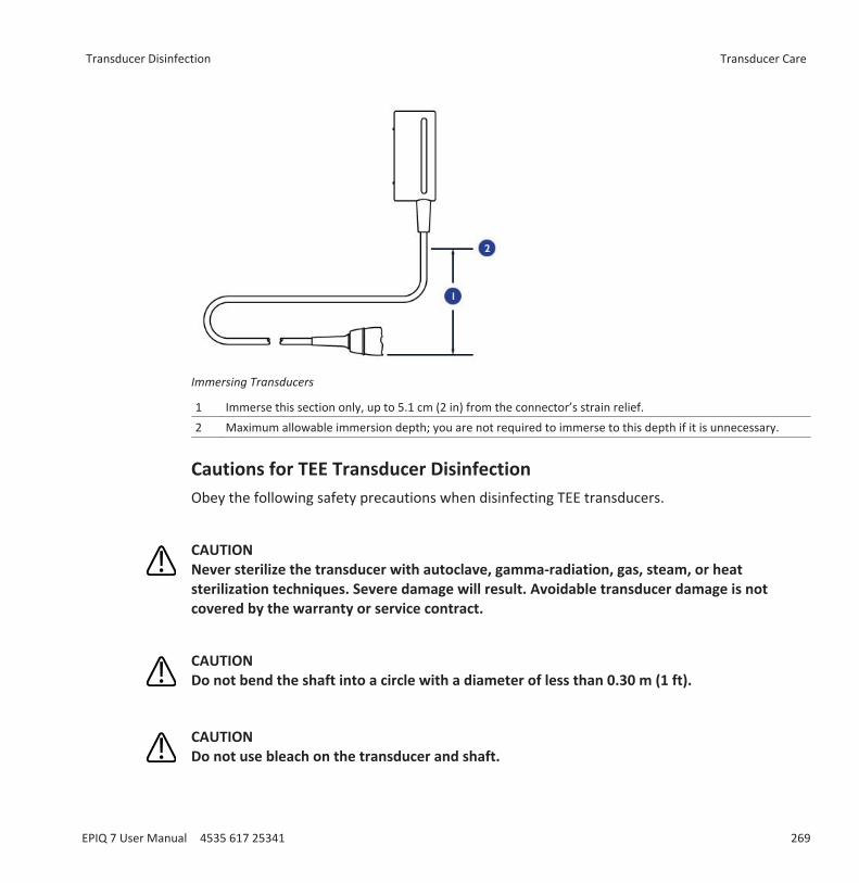
Immersing Transducers
1 Immerse this section only, up to 5.1 cm (2 in) from the connector’s strain relief.2 Maximum allowable immersion depth; you are not required to immerse to this depth if it is unnecessary.
Cautions for TEE Transducer DisinfectionObey the following safety precautions when disinfecting TEE transducers.
CAUTIONNever sterilize the transducer with autoclave, gamma-radiation, gas, steam, or heatsterilization techniques. Severe damage will result. Avoidable transducer damage is notcovered by the warranty or service contract.
CAUTIONDo not bend the shaft into a circle with a diameter of less than 0.30 m (1 ft).
CAUTIONDo not use bleach on the transducer and shaft.
Transducer Disinfection Transducer Care
EPIQ 7 User Manual 4535 617 25341 269
CAUTIONDo not use isopropyl alcohol-based products on the transducer and shaft.
CAUTIONDo not soak the transducer for extended periods of time. Limit the time that transducers aresoaked in disinfectant solution to the minimum time recommended by the disinfectantmanufacturer.
CAUTIONDo not rinse or immerse the control housing, cable, connector, or the portion of the cablenear the connector.
CAUTIONDo not immerse or rinse the steering mechanism.
CAUTIONFollow the recommendations of the disinfectant manufacturer.
CAUTIONThe transducer steering mechanism is unsealed. If disinfectant or other fluid enters thesteering mechanism, it corrodes the gears and electrical connections. Avoidable transducerdamage is not covered by the warranty or service contract.
Disinfecting TEE Transducers by ImmersionBefore performing this procedure, read the cautions and warnings in “Transducer Disinfectionby Immersion” on page 266, “Transducer Care Safety” on page 255, and “Minimizing the Effectsof Residual Disinfectant” on page 267.
Disinfection by immersion is the accepted method of infection control for transesophagealtransducers. Philips recommends that a protective transducer cover be used during studies.
Transducer Care Transducer Disinfection
270 EPIQ 7 User Manual 4535 617 25341
Upon receiving your new transducer, disinfect it before performing the first study. Clean anddisinfect the transducer immediately after each use to protect patients and personnel from avariety of pathogens. Establish and clearly post a cleaning procedure that includes the followingsteps.
Methods for disinfecting transesophageal (TEE) and non-TEE transducers differ. For non-TEEtransducers, see “Disinfecting Non-TEE Transducers by Immersion” on page 268.1. Disconnect the transducer from the system.2. Clean the transducer and flexible shaft using any of the following: enzymatic cleaner, mild
soap solution, or an approved wipe. Follow the manufacturer's instructions for use.3. Use water to rinse the distal tip and flexible shaft thoroughly.4. Immerse the distal tip and flexible shaft into the appropriate disinfectant as shown in the
illustration.5. Remove the tip and shaft from the disinfectant and thoroughly rinse with water according
to the instructions from the disinfectant manufacturer.6. Check the transducer for any residual organic material. If any is present, remove it and
disinfect the transducer again.7. Gently dry the distal tip and flexible shaft with a sterile cloth or pad, or allow it to air dry.8. Lightly wipe only the steering mechanism and handle with a pad moistened with rubbing
alcohol (70% isopropyl alcohol), or use approved cleaners as directed on the handle andsteering mechanism.
9. Hang the transducer on a wall-mounted rack, and let it air dry.
Transducer Disinfection Transducer Care
EPIQ 7 User Manual 4535 617 25341 271
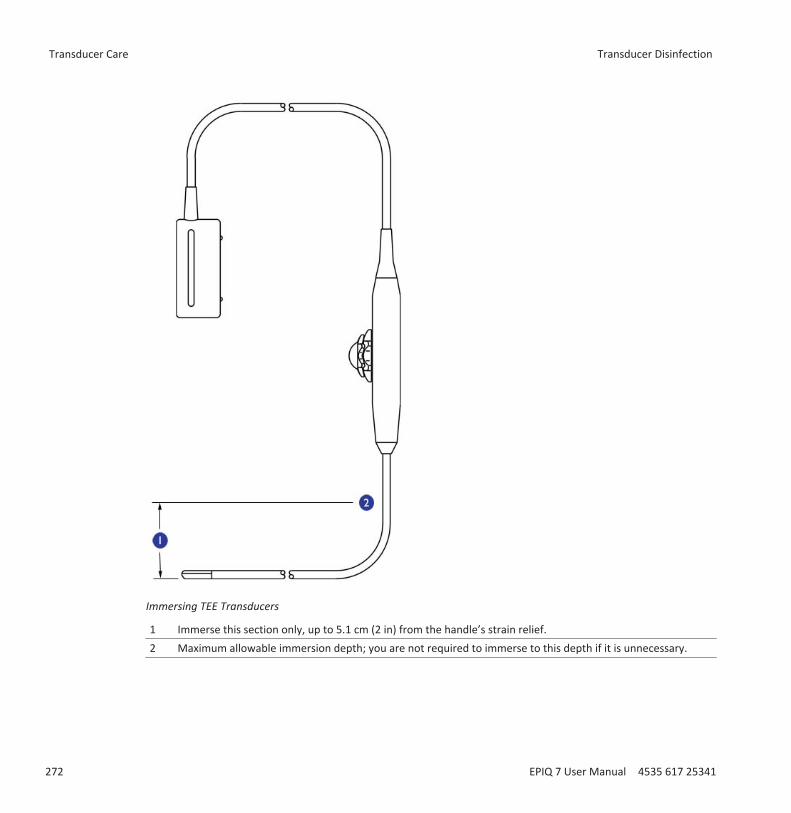
Immersing TEE Transducers
1 Immerse this section only, up to 5.1 cm (2 in) from the handle’s strain relief.2 Maximum allowable immersion depth; you are not required to immerse to this depth if it is unnecessary.
Transducer Care Transducer Disinfection
272 EPIQ 7 User Manual 4535 617 25341

Disinfecting TEE Transducers with an AERBefore performing this procedure, read the cautions and warnings in “Transducer Disinfectionby Immersion” on page 266, “Transducer Care Safety” on page 255, “Cautions for TEETransducer Disinfection” on page 269, and “Minimizing the Effects of Residual Disinfectant” onpage 267.
The automated endoscopy reprocessor (AER) disinfector can be used only with thosetransducers listed that are listed as compatible in the “Disinfectants and Cleaning SolutionsCompatibility Table” on page 278 or in the results of a compatible-solution search on theTransducer Care website:
www.healthcare.philips.com/us_en/products/ultrasound/Transducers/transducer_care/index.wpd
Methods for disinfecting transesophageal (TEE) and non-TEE transducers differ. For non-TEEtransducers, see “Disinfecting Non-TEE Transducers by Immersion” on page 268.1. Disconnect the transducer from the system.2. Follow the manufacturers' instructions for disinfection.
Transducer SterilizationSterilization is required if the transducer enters otherwise sterile tissue without a sterile cover.If you use a sterile cover, you should sterilize but you can disinfect (high-level disinfection). Forinformation about disinfecting a transducer, see “Transducer Disinfection” on page 263.
WARNINGAlways use protective eyewear and gloves when cleaning, disinfecting, or sterilizing anyequipment.
WARNINGIn intraoperative applications, sterilized transducers should be used with sterile gel and asterile transducer cover.
Transducer Disinfection Transducer Care
EPIQ 7 User Manual 4535 617 25341 273
WARNINGSterile transducer covers are disposable and must not be reused.
WARNINGIf a premixed solution is used, be sure to observe the solution expiration date.
CAUTIONTransducers must be cleaned after each use. Cleaning the transducer is an essential stepbefore effective disinfection or sterilization. Be sure to follow the manufacturer’s instructionswhen using disinfectants.
CAUTIONUse only liquid solutions to sterilize transducers. Using autoclave, gas (EtO), or other methodsnot approved by Philips will damage your transducer and void your warranty.
CAUTIONDo not allow sharp objects, such as scalpels and cauterizing knives, to touch transducers orcables.
CAUTIONWhen handling a transducer, do not bump the transducer on hard surfaces.
CAUTIONEnsure the solution strength and duration of contact are appropriate for sterilization. Be sureto follow the manufacturer’s instructions.
Transducer Care Transducer Sterilization
274 EPIQ 7 User Manual 4535 617 25341
Sterilizing Transducers by ImmersionThe main difference between sterilization by immersion and disinfection by immersion is thelength of time the transducer is immersed. To determine if your transducer requiressterilization or high-level disinfection, see “Choosing the Correct Transducer-Care Method” onpage 257.1. Clean the transducer and cable according to the procedures in “Transducer, Cable, and
Connector Cleaning” on page 258.2. Mix the sterilization solution compatible with your transducer according to label
instructions for solution strength.3. Immerse the transducer in the sterilization solution as shown in the illustration.4. Follow the instructions on the sterilization label for the duration of transducer immersion
required for sterilization.5. Remove the transducer from the sterilization solution after the recommended sterilization
time has elapsed.6. Using the instructions on the sterilization label, rinse the transducer in sterile water up to
the point of immersion, and then air dry or towel dry with a sterile cloth.7. Examine the transducer for damage, such as cracks, splitting, fluid leaks, or sharp edges or
projections. If damage is evident, discontinue use of the transducer, and contact yourPhilips representative.
Transducer Sterilization Transducer Care
EPIQ 7 User Manual 4535 617 25341 275

Immersing Transducers
1 Immerse this section only, up to 5.1 cm (2 in) from the connector’s strain relief.2 Maximum allowable immersion depth; you are not required to immerse to this depth if it is unnecessary.
Disinfectants CompatibilityRead this information before performing disinfection and sterilization procedures. It discussesrecommended disinfectants and choosing an appropriate disinfectant for the required level ofdisinfection. You must check “Disinfectants and Cleaning Solutions Compatibility Table” on page278 for the chemical compatibility of disinfectants and cleaners with specific transducers. Inaddition, the table indicates if a device can be sprayed or wiped only, or if it can be soaked.
Transducer Care Disinfectants Compatibility
276 EPIQ 7 User Manual 4535 617 25341
WARNINGNot all disinfectants are effective against all types of contamination. Ensure the disinfectanttype is appropriate for the type of transducer and that the solution strength and time ofcontact are appropriate for the intended clinical use.
WARNINGDisinfectants listed in this section are recommended because of their chemical compatibilitywith product materials, not their biological effectiveness. For the biological effectiveness of adisinfectant, see the guidelines and recommendations of the disinfectant manufacturer, theAssociation for Professionals in Infection Control, the U.S. Food and Drug Administration, andthe U.S. Centers for Disease Control.
WARNINGIf a premixed solution is used, be sure to observe the solution expiration date.
WARNINGAlways use protective eyewear and gloves when cleaning and disinfecting any equipment.
CAUTIONUsing a non-recommended disinfection solution, using an incorrect solution strength, orimmersing a transducer deeper or longer than recommended can damage the device andvoids the warranty.
Disinfectant Types
WARNINGThe level of disinfection required for a device is dictated by the type of tissue it will contactduring use. Ensure the disinfectant type is appropriate for the type of transducer and thetransducer application. For information on the levels of disinfection requirements, see
Disinfectants Compatibility Transducer Care
EPIQ 7 User Manual 4535 617 25341 277
“Choosing the Correct Transducer-Care Method” on page 257. For more information, see thedisinfectant label instructions and the recommendations of the Association for Professionalsin Infection Control, the U.S. Food and Drug Administration, and the U.S. Centers for DiseaseControl.
CAUTIONIf you use an isopropyl alcohol-based product for disinfection, ensure the solution is only 70%alcohol or less. Solutions of more than 70% alcohol can cause product damage. Do not usealcohol on the transducer’s strain relief or cable, or on TEE transducers (except the handle).
See “Disinfectants Compatibility” on page 276 for standard industry recommendations ondisinfection, for information that can help you choose an appropriate disinfectant for therequired level of disinfection, and for transducer-specific instructions.
Factors Affecting Disinfectant EfficiencyThe following factors will affect the efficiency of a disinfectant solution:• Number and location of microorganisms• Innate resistance of microorganisms• Concentration and potency of disinfectants• Physical and chemical factors• Organic and inorganic matter• Duration of exposure• Biofilms
Disinfectants and Cleaning Solutions Compatibility TableThe following table lists the disinfectants and cleaning solutions that are compatible with thetransducers available for your ultrasound system.
CAUTIONDo not use hydrogen-peroxide products on Doppler transducers.
Transducer Care Disinfectants Compatibility
278 EPIQ 7 User Manual 4535 617 25341
CAUTIONIsopropyl alcohol (IPA) products are approved for use on the transducer only and only if theIPA content does not exceed 70%. Do not use IPA-based products on the connector cable andstrain relief. All other product types listed here can be used on the transducer and cable.
NOTETEE transducers require unique methods for disinfection. See “Disinfecting TEE Transducers byImmersion” on page 270 or “Disinfecting TEE Transducers with an AER” on page 273.
Based on material compatibility testing and product use profile and active ingredients, Philipshas approved for use the following types of low-level disinfectants used as a spray or wipe forsurface (skin contact) and transvaginal or transrectal probes:• Sodium hypochlorite based (for example 10% household bleach solution with active sodium
hypochlorite at approximately 0.6%)• Quaternary ammonium (QUAT) based (for example, products that contain n-alkyl (x)benzyl
ammonium chloride solution where (x) can be any organic functional group such as ethyland methyl, and so on; concentration at use should be less than 0.5% total for all QUATslisted)
• Accelerated hydrogen peroxide based, except on Doppler transducers (D2cwc, D2tcd, andD5cwc)
• Activated hydrogen peroxide based, except on Doppler transducers (D2cwc, D2tcd, andD5cwc)
• Alcohol or alcohol plus QUAT based (product alcohol content cannot exceed 70%)
Products not specifically listed in the following table but with similar active ingredients, asindicated above, and marketed for medical use may be used. Because of the large number ofproducts available, it is impossible to have an all-inclusive list. If you are unsure of the suitabilityof a particular product, please contact your Philips representative for assistance.
For more information:• Philips Ultrasound Transducer Care website (www.healthcare.philips.com/us/products/
ultrasound/transducers/transducer_care/)• In North America, call Philips at 800-722-9377.• Outside North America, contact your local Philips representative.
Disinfectants Compatibility Transducer Care
EPIQ 7 User Manual 4535 617 25341 279
Disinfectants and Cleaning Solutions Compatibility Table LegendOrigin (Country Code) Application Definitions Special InstructionsAU = Australia T = Approved for use on the transducer 1. Soak or per product instructionsCA = Canada C = Approved for use on the cable --DE = Germany H =Approved for use on the handle housing --ES = Spain N = Not approved for use --FR = France -- --UK = United Kingdom -- --US = United States -- --
Disinfectants and Cleaning Solutions CompatibilitySolution Origin Qualified
UseActiveIngredients
C5-1C8-5C9-2C10-3vC10-4ec
D2cwcD2tcdD5cwc
L12-3L12-5 50L15-7ioL18-5
S5-1S8-3S12-4
S7-3t V6-2 X5-1 X6-1 X7-2t
70% IsopropylAlcohol
All Spray/Wipe
Alcohol T T T T H T T T H
AbcoCide US Soak1 Glutaraldehyde T,C N T,C T,C T T,C T,C T,C TAbcoCide 28 US Soak1 Glutaraldehyde T,C N T,C T,C T T,C T,C T,C TAccel Wipes CA Wipe Hydrogen
PeroxideT,C N T,C T,C N T,C T,C T,C T,C,H
Aidal AU Soak1 Glutaraldehyde T,C N T,C T,C T T,C T,C T,C TAidal Plus AU Soak1 Glutaraldehyde T,C N T,C T,C T T,C T,C T,C TAlkaspray FR Spray/
WipeAlcohol,Alkylamine
T T T T H T T T H
AmpholysineBasique
FR Spray/Wipe
Biguanide/Quat.Ammonia
T,C T,C T,C T,C T,C T,C T,C T,C T,C
Aniosept Activ FR Soak1 Peracetic Acid T,C N T,C T,C N T,C T,C T,C TAnioxyde 1000 FR Soak1 Peracetic Acid T,C N T,C T,C N T,C T,C T,C TAntigermix AE1 FR AE1
SystemUV-C N N N N N N N N T
Transducer Care Disinfectants Compatibility
280 EPIQ 7 User Manual 4535 617 25341
Solution Origin QualifiedUse
ActiveIngredients
C5-1C8-5C9-2C10-3vC10-4ec
D2cwcD2tcdD5cwc
L12-3L12-5 50L15-7ioL18-5
S5-1S8-3S12-4
S7-3t V6-2 X5-1 X6-1 X7-2t
Antigermix S1 FR S1System
UV-C T,C N T,C T,C N N T,C T,C N
Banicide US Soak1 Glutaraldehyde T,C N T,C T,C T T,C T,C T,C TBleach (10%solution of5.25% Bleach)
All Spray/Wipe
SodiumHypochlorite
T,C T,C T,C T,C C T,C T,C T,C C
CaviWipes US Wipe Alcohol, Quat.Ammonia
T T T T H T T T H
Cidex US Soak1 Glutaraldehyde T,C N T,C T,C T T,C T,C T,C TCidex 7 US Soak1 Glutaraldehyde T,C N T,C T,C T T,C T,C T,C TCidex OPA US Soak1 Ortho-phthal
aldehydeT,C N T,C T,C T T,C T,C T,C T
Cidex PAE 14J FR Soak1 Glutaraldehyde T,C N T,C T,C T T,C T,C T,C TCidex Plus US Soak1 Glutaraldehyde T,C N T,C T,C T T,C T,C T,C TCleaniseptWipes
DE Spray/Wipe
Quat.Ammonia
T,C T,C T,C T,C T,C,H T,C T,C T,C T,C,H
Descoton Extra DE Soak1 Glutaraldehyde T,C N T,C T,C T T,C T,C T,C TDispatch US Spray/
WipeSodiumHypochlorite
T,C T,C T,C T,C C T,C T,C T,C C
Endo FC FR Soak1 Glutaraldehyde T,C N T,C T,C T T,C T,C T,C TEndosporine FR Soak1 Glutaraldehyde T,C N T,C T,C T T,C T,C T,C TEnzol US Pre-
cleanerEnzymes T,C N T,C T,C T T,C T,C T,C T
Epizyme Rapid AU Pre-cleaner
Enzymes T,C N T,C T,C T T,C T,C T,C T
Gigasept FF(neu)
DE Soak1 Succinicdialdehyde
T,C N T,C T,C T T,C T,C T,C T
Gigasept PAA DE Soak1 Peracetic T,C N T,C T,C N T,C T,C T,C T
Disinfectants Compatibility Transducer Care
EPIQ 7 User Manual 4535 617 25341 281
Solution Origin QualifiedUse
ActiveIngredients
C5-1C8-5C9-2C10-3vC10-4ec
D2cwcD2tcdD5cwc
L12-3L12-5 50L15-7ioL18-5
S5-1S8-3S12-4
S7-3t V6-2 X5-1 X6-1 X7-2t
Incidin DE Spray/Wipe
Alcohol T T T T H T T T H
Incidur Spray DE Spray/Wipe
Alcohol, Quat.Aldehyde
T T T T H T T T H
Instruzyme FR Pre-cleaner
Enzymes, Quat.Ammonia,Biguanide
T,C N T,C N T T,C N T,C T
Klenzyme US Pre-cleaner
Enzymes T,C N T,C T,C T T,C T,C T,C T
Kohrsolin DE Soak1 Glutaraldehyde T,C N T,C T,C T T,C T,C T,C TKorsolex Basic FR Soak1 Aldehyde
ReleasingT,C N T,C T,C T T,C T,C T,C T
Korsolex Extra FR Soak1 Aldehydes/QuaternaryAmmonium
T,C N T,C T,C T T,C T,C T,C T
Korsolex PAE FR Soak1 Glutaraldehyde T,C N T,C T,C T T,C T,C T,C TMaxiCide Plus US Soak1 Glutaraldehyde T,C N T,C T,C T T,C T,C T,C TMedDis UK Soak1 Quat.
Ammonia,Sulfamic Acid
T,C N T,C T,C T T,C T,C T,C T
Medistel UK Soak1 Quat.Ammonia,Sulfamic Acid
T,C N T,C T,C T T,C T,C T,C T
MetriCide US Soak1 Glutaraldehyde T,C N T,C T,C T T,C T,C T,C TMetriCide 28 US Soak1 Glutaraldehyde T,C N T,C T,C T T,C T,C T,C TMetriCide OPAPlus
US Soak1 Ortho-phthalaldehyde
T,C N T,C T,C T T,C T,C T,C T
MetriCide Plus30
US Soak1 Glutaraldehyde T,C N T,C T,C T T,C T,C T,C T
Transducer Care Disinfectants Compatibility
282 EPIQ 7 User Manual 4535 617 25341

Solution Origin QualifiedUse
ActiveIngredients
C5-1C8-5C9-2C10-3vC10-4ec
D2cwcD2tcdD5cwc
L12-3L12-5 50L15-7ioL18-5
S5-1S8-3S12-4
S7-3t V6-2 X5-1 X6-1 X7-2t
MetriZyme US Pre-cleaner
Enzymes T,C N T,C T,C T T,C T,C T,C T
Mikrozid PAA DE Wipe Peracetic Acid T,C N T,C T,C N T,C T,C T,C TMild SoapSolution
All Pre-cleaner
Surfactants/Soap
T,C T,C T,C T,C T,C T,C T,C T,C T,C
Milton AU Spray/Wipe
SodiumHypochlorite
T,C T,C T,C T,C C T,C T,C T,C C
NDP MedConcentratedPlus
SP Soak1 N-Duopropenide,Alkylamine
T,C N T,C T,C T T,C T,C T,C T
Omnicide 14NS US Soak1 Glutaraldehyde T,C N T,C T,C T T,C T,C T,C TOmnicide 28 US Soak1 Glutaraldehyde T,C N T,C T,C T T,C T,C T,C TOpti-Cide 3 US Spray/
WipeAlcohol, Quat.Ammonia
T T T T H T T T H
Oxivir US Wipe HydrogenPeroxide
T,C N T,C T,C N T,C T,C T,C T,C,H
Peracetic AcidOCS
UK Soak1 Peracetic Acid T,C N T,C T,C N T,C T,C T,C T
PeraSafePowder
UK Soak1 Peracetic Acid T,C N T,C T,C T T,C T,C T,C T
Perastel(formerlyPerascope)
UK Soak1 Peracetic Acid T,C N T,C T,C N T,C T,C T,C T
PerCept Wipes CA Wipe HydrogenPeroxide
T,C N T,C T,C T,C,H T,C T,C T,C T,C,H
Phagocide D FR Soak1 Glutaraldehyde T,C N T,C T,C T T,C T,C T,C TPhagozyme ND FR Pre-
cleanerEnzymes, Quat.Ammonium
T,C N T,C N T T,C N T,C T
Pro-Cide US Soak1 Glutaraldehyde T,C N T,C T,C T T,C T,C T,C T
Disinfectants Compatibility Transducer Care
EPIQ 7 User Manual 4535 617 25341 283
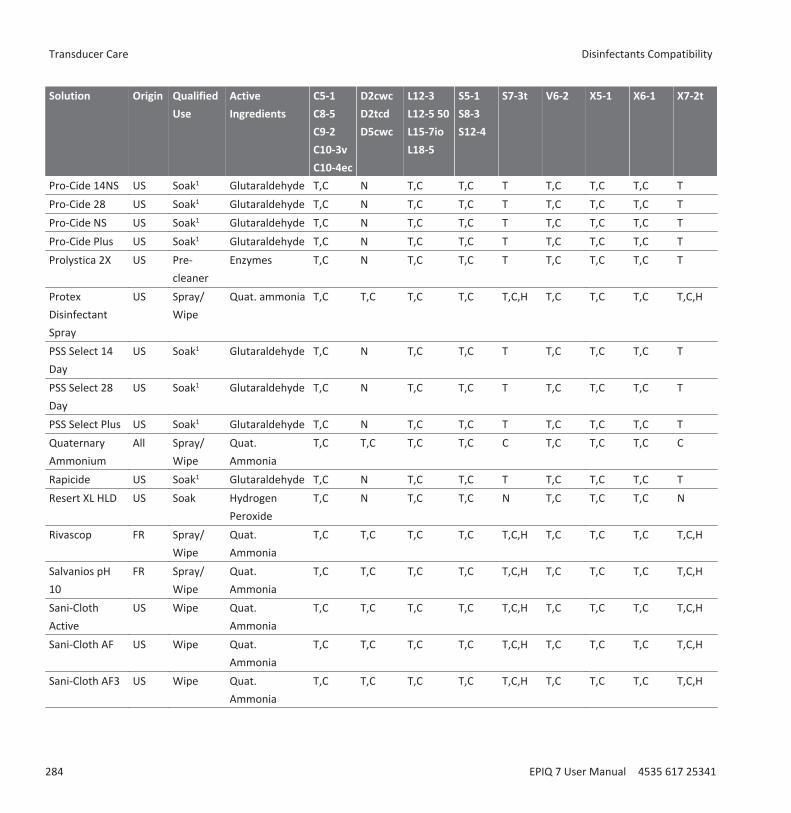
Solution Origin QualifiedUse
ActiveIngredients
C5-1C8-5C9-2C10-3vC10-4ec
D2cwcD2tcdD5cwc
L12-3L12-5 50L15-7ioL18-5
S5-1S8-3S12-4
S7-3t V6-2 X5-1 X6-1 X7-2t
Pro-Cide 14NS US Soak1 Glutaraldehyde T,C N T,C T,C T T,C T,C T,C TPro-Cide 28 US Soak1 Glutaraldehyde T,C N T,C T,C T T,C T,C T,C TPro-Cide NS US Soak1 Glutaraldehyde T,C N T,C T,C T T,C T,C T,C TPro-Cide Plus US Soak1 Glutaraldehyde T,C N T,C T,C T T,C T,C T,C TProlystica 2X US Pre-
cleanerEnzymes T,C N T,C T,C T T,C T,C T,C T
ProtexDisinfectantSpray
US Spray/Wipe
Quat. ammonia T,C T,C T,C T,C T,C,H T,C T,C T,C T,C,H
PSS Select 14Day
US Soak1 Glutaraldehyde T,C N T,C T,C T T,C T,C T,C T
PSS Select 28Day
US Soak1 Glutaraldehyde T,C N T,C T,C T T,C T,C T,C T
PSS Select Plus US Soak1 Glutaraldehyde T,C N T,C T,C T T,C T,C T,C TQuaternaryAmmonium
All Spray/Wipe
Quat.Ammonia
T,C T,C T,C T,C C T,C T,C T,C C
Rapicide US Soak1 Glutaraldehyde T,C N T,C T,C T T,C T,C T,C TResert XL HLD US Soak Hydrogen
PeroxideT,C N T,C T,C N T,C T,C T,C N
Rivascop FR Spray/Wipe
Quat.Ammonia
T,C T,C T,C T,C T,C,H T,C T,C T,C T,C,H
Salvanios pH10
FR Spray/Wipe
Quat.Ammonia
T,C T,C T,C T,C T,C,H T,C T,C T,C T,C,H
Sani-ClothActive
US Wipe Quat.Ammonia
T,C T,C T,C T,C T,C,H T,C T,C T,C T,C,H
Sani-Cloth AF US Wipe Quat.Ammonia
T,C T,C T,C T,C T,C,H T,C T,C T,C T,C,H
Sani-Cloth AF3 US Wipe Quat.Ammonia
T,C T,C T,C T,C T,C,H T,C T,C T,C T,C,H
Transducer Care Disinfectants Compatibility
284 EPIQ 7 User Manual 4535 617 25341
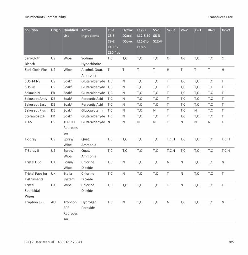
Solution Origin QualifiedUse
ActiveIngredients
C5-1C8-5C9-2C10-3vC10-4ec
D2cwcD2tcdD5cwc
L12-3L12-5 50L15-7ioL18-5
S5-1S8-3S12-4
S7-3t V6-2 X5-1 X6-1 X7-2t
Sani-ClothBleach
US Wipe SodiumHypochlorite
T,C T,C T,C T,C C T,C T,C T,C C
Sani-Cloth Plus US Wipe Alcohol, Quat.Ammonia
T T T T H T T T H
SDS 14 NS US Soak1 Glutaraldehyde T,C N T,C T,C T T,C T,C T,C TSDS 28 US Soak1 Glutaraldehyde T,C N T,C T,C T T,C T,C T,C TSekucid N FR Soak1 Glutaraldehyde T,C N T,C T,C T T,C T,C T,C TSekusept Aktiv DE Soak1 Peracetic Acid T,C N T,C T,C T T,C T,C T,C TSekusept Easy DE Soak1 Peracetic Acid T,C N T,C T,C T T,C T,C T,C TSekusept Plus DE Soak1 Glucoprotamin T,C N T,C N T T,C N T,C TSteranios 2% FR Soak1 Glutaraldehyde T,C N T,C T,C T T,C T,C T,C TTD-5 US TD-100
Reprocessor
Glutaraldehyde N N N N T N N N T
T-Spray US Spray/Wipe
Quat.Ammonia
T,C T,C T,C T,C T,C,H T,C T,C T,C T,C,H
T-Spray II US Spray/Wipe
Quat.Ammonia
T,C T,C T,C T,C T,C,H T,C T,C T,C T,C,H
Tristel Duo UK Foam/Wipe
ChlorineDioxide
T,C N T,C T,C N N T,C T,C N
Tristel Fuse forInstruments
UK StellaSystem
ChlorineDioxide
T,C N T,C T,C T N T,C T,C T
TristelSporicidalWipes
UK Wipe ChlorineDioxide
T,C T,C T,C T,C T N T,C T,C T
Trophon EPR AU TrophonEPRReprocessor
HydrogenPeroxide
T,C N T,C T,C N T,C T,C T,C N
Disinfectants Compatibility Transducer Care
EPIQ 7 User Manual 4535 617 25341 285
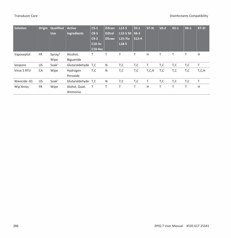
Solution Origin QualifiedUse
ActiveIngredients
C5-1C8-5C9-2C10-3vC10-4ec
D2cwcD2tcdD5cwc
L12-3L12-5 50L15-7ioL18-5
S5-1S8-3S12-4
S7-3t V6-2 X5-1 X6-1 X7-2t
Vaposeptol FR Spray/Wipe
Alcohol,Biguanide
T T T T H T T T H
Vespore US Soak1 Glutaraldehyde T,C N T,C T,C T T,C T,C T,C TVirox 5 RTU CA Wipe Hydrogen
PeroxideT,C N T,C T,C T,C,H T,C T,C T,C T,C,H
Wavicide -01 US Soak1 Glutaraldehyde T,C N T,C T,C T T,C T,C T,C TWip'Anios FR Wipe Alohol, Quat.
AmmoniaT T T T H T T T H
Transducer Care Disinfectants Compatibility
286 EPIQ 7 User Manual 4535 617 25341

System MaintenanceMaintenance should be performed regularly and as needed.
Because the system is a piece of medical equipment that contains several circuit boards,extensive service diagnostics, and complex operating software, Philips recommends that onlytrained personnel service the system.
Cleaning and Maintaining the SystemIt is important to clean and maintain the ultrasound system and peripherals. Thorough cleaningis particularly important for pieces of peripheral equipment, because they containelectromechanical devices. If exposed to constant and excessive environmental dust andhumidity, these devices will suffer in both performance and reliability.
It is essential to clean the transducers used with your ultrasound system. The cleaningprocedures vary for the different types of transducers and their uses.
For detailed instructions on how to clean and maintain each type of transducer used with thesystem, including disinfectant compatibility, see the “Transducer Care” section.
Cleaning the System and ECG EquipmentUse this method to clean the system and the ECG cables, leads, and electrodes. You can use amild soap solution. If the equipment has come in contact with blood or infectious material,clean the equipment with a 70% solution of isopropyl alcohol. For instructions on disinfectingsystem surfaces, see “Disinfecting System Surfaces” on page 290.
WARNINGAlways use protective eyewear and gloves when cleaning and disinfecting any equipment.
CAUTIONAttempting to disinfect a cable or connector by using a method other than the one includedhere can damage the device and voids the warranty.
14
Cleaning and Maintaining the System System Maintenance
EPIQ 7 User Manual 4535 617 25341 287

CAUTIONOrient the parts that must remain dry higher than the wet parts until all parts are dry.
Use the following procedure to clean the display; the system control panel; all the externalsurfaces of the system and the cart; and the ECG trunk cables, leads, and electrodes.1. Before cleaning, turn off the system and unplug the power cord from the power source.2. Wipe with a soft cloth moistened with soap and water.
CAUTIONDo not spill or spray liquid on the controls, into the system cabinet, or into the transducerconnection receptacle.
3. Remove any solid matter around the keys or the controls with a cotton swab or toothpick toensure that solids are not pushed into the cabinet.
4. If blood or other infectious material comes in contact with the system or any cable otherthan a transducer cable, wipe with a 70% solution of isopropyl alcohol.
CAUTIONIf blood or other infectious material comes in contact with a transducer or transducer cable,do not wipe with isopropyl alcohol until you have read the “Transducer Care” section forspecific cleaning guidelines. Isopropyl alcohol should not be used on some parts of thetransducer and should never be used on any parts of the transducer cable. Additionalcleaning agents are also available for transducers.
CAUTIONDo not use strong solvents, common cleaning products, or abrasive cleansers, which willdamage the system surfaces.
CAUTIONDo not touch the displays with sharp objects or use paper towels to clean them, which maydamage them.
System Maintenance Cleaning and Maintaining the System
288 EPIQ 7 User Manual 4535 617 25341

5. Remove dust from the monitor screen and touch screen with a soft, lint-free cloth. A micro-fiber cloth is recommended. Clean the monitor screen and touch screen using a liquidscreen cleaner specifically designed for LCDs. Spray the liquid onto the cleaning cloth orspray sparingly onto the displays. You can also use pre-moistened screen wipes. Dry thedisplays with a soft, lint-free cloth.
CAUTIONWhen cleaning the system control panel, monitor screen, touch screen, and keyboard, takecare not to get any solution inside the housings. Also take care not to scratch the face of themonitor while cleaning it.
CAUTIONDo not use cleaners containing bleach on the touch screen. It may damage the surface.
6. Remove any residue with a cloth moistened with sterile water.7. Be sure to dry the equipment to prevent potential corrosion.
Disinfectants for System SurfacesThe exterior surfaces of the system can be disinfected using a compatible disinfectant with awipe method.
System surfaces include the monitor screen, the touch screens, and plastic and paintedsurfaces. The following products can be used on system surfaces:• Mild soap solution• 70% isopropyl alcohol (IPA)• T-Spray II (quaternary ammonium-based)• Opti-Cide 3 (quaternary ammonium/isopropyl alcohol-based)• Sani-Cloth HB (quaternary ammonium-based)• Sani-Cloth Plus (quaternary ammonium/isopropyl alcohol-based)• 0.5% Accelerated hydrogen peroxide
Other products that are based on quaternary ammonium compounds (QUAT) or QUAT/isopropyl alcohol can also be used in disinfecting system surfaces.
Cleaning and Maintaining the System System Maintenance
EPIQ 7 User Manual 4535 617 25341 289
Disinfecting System Surfaces
WARNINGAlways use protective eyewear and gloves when cleaning and disinfecting any equipment.
CAUTIONUse only compatible disinfectants on system surfaces.
CAUTIONIf you use an isopropyl alcohol solution for disinfection, ensure the solution is only 70%alcohol or less. Solutions of more than 70% alcohol can cause product damage.
Before performing this procedure, read “Disinfectants for System Surfaces” on page 289.1. Turn off the system and disconnect the system power cord from the wall outlet.2. Use a soft cloth lightly dampened in a mild soap or detergent solution to clean exterior
surfaces on the system.3. Mix the disinfection solution compatible with your system according to label instructions
for solution strength.
CAUTIONDo not spray disinfectant directly on system surfaces. When wiping, do not allow disinfectantto pool or run on system surfaces. In either case, disinfectant may leak into the system,damaging the system and voiding the warranty. Wipe only with a cloth or applicator that islightly dampened.
4. Wipe system surfaces with the disinfectant, following disinfectant label instructions forwipe durations, solution strengths, and disinfectant contact duration. Ensure the solutionstrength and duration of contact are appropriate for the intended clinical application.
System Maintenance Cleaning and Maintaining the System
290 EPIQ 7 User Manual 4535 617 25341
5. Air dry or towel dry with a sterile cloth according to the instructions on the disinfectantlabel.
6. Because the system is a piece of medical equipment that contains several circuit boards,extensive service diagnostics, and complex operating software, Philips recommends thatonly trained personnel service the system.
System Control Panel MaintenanceThe system control panel and other outer surfaces are most likely to be affected by liquid spillsand other materials such as excessive amounts of gel. These materials may seep into electricalcomponents under the panel and cause intermittent failures. During preventive maintenance,look for such potential problems including loose knobs and worn controls.
Regularly clean the outside of the system as described in “Cleaning the System and ECGEquipment” on page 287.
Cleaning the TrackballCleaning the trackball regularly prolongs its useful life and prevents service calls.1. With your fingers, unscrew the ring around the trackball.2. Lift the trackball out of the mounting area.3. Clean the trackball and the mounting area with a lint-free cloth or a small brush.4. Place the ball back on the mounting area.5. With your fingers, screw the ring back on.
Cleaning the System Air FilterThe system air filters should be inspected every week and cleaned as needed. The air filter islocated in a slot at the bottom left side of the system. If you decide to clean the air filters withsoap and water, you may want to install a spare filter while the other filter is drying. Additionalair filters can be ordered from Philips.
WARNINGBefore performing maintenance or cleaning, always turn off the system, and then disconnectthe system from the wall outlet.
Cleaning and Maintaining the System System Maintenance
EPIQ 7 User Manual 4535 617 25341 291
CAUTIONTurn off power before you remove the air filter. Do not turn on power without the air filterinstalled.
CAUTIONEnsure that air filter is dry before installing it. Installing a wet or damp air filter can damagethe system.
1. Locate the air filter handle at the bottom of the left side of the system.2. Pull the air filter handle straight out, until the filter is completely removed from the system.3. Inspect the filter. Depending on the condition of the air filter, vacuum or rinse the filter with
water to clean it. If the filter is worn out, or cannot be cleaned, replace it with a spare.4. To reinstall the filter, slide the filter into place at the bottom of the left side of the system.
System Maintenance Cleaning and Maintaining the System
292 EPIQ 7 User Manual 4535 617 25341

Removing the System Air Filter
Specifying and Resetting the Air Filter Maintenance Status1. Press Support.2. In Philips SupportConnect, click Test/Utilities.3. Click Check Filter Status.4. To change the cleaning interval for the air filter, under Filter Cleaning, type the number of
days in Interval.5. To reset the interval after cleaning the filter, under Filter Cleaned, click Done.6. To exit SupportConnect, touch Close.
Transducer MaintenanceTransducers require proper care, cleaning, and handling. Reasonable care includes inspection,cleaning, and disinfection or sterilization, as necessary.
Cleaning and Maintaining the System System Maintenance
EPIQ 7 User Manual 4535 617 25341 293
Inspect the transducer cable, case, and lens before each use. Check for cracks or other damagethat jeopardizes the integrity of the transducer. Report any damage to your Philips customerservice representative, and discontinue use of the transducer.
For all information on transducer cleaning and disinfection, see the “Transducer Care” section.For all information about the use of acoustic coupling gels, see “Ultrasound Transmission Gels”on page 184.
CAUTIONSome ultrasound coupling gels, as well as some solutions for precleaning, disinfecting, andsterilizing can damage a transducer. Before using a gel or solution on a transducer, see“Ultrasound Transmission Gels” on page 184 or the “Transducer Care” section. You can alsocontact your local Philips representative. For contact information, see “Customer Service” onpage 22.
If you encounter poor image quality or transducer problems, see “Troubleshooting” on page295.
Printer and DVD Recorder MaintenanceBefore performing any maintenance on a device, observe the following warnings and cautions:
WARNINGIf the device is internal to the system, turn off the system and disconnect the system from thewall outlet. If the device is external to the system, disconnect the device from the wall outlet.
CAUTIONDo not scratch the roller or allow dirt and dust to contact the roller of a printer.
CAUTIONDo not use strong solvents such as thinner or acetone, or abrasive cleaners, because thosewill damage a device cabinet.
System Maintenance Printer and DVD Recorder Maintenance
294 EPIQ 7 User Manual 4535 617 25341
CAUTIONDo not unplug the system from the wall outlet until the system is completely off. If youunplug your system before the shutdown message appears, you will have to wait longer thanusual to use your system the next time you turn it on. You may also corrupt files, which canresult in an inoperative system or the loss of patient data.
Periodically clean the external surfaces of a device with a soft cloth. Difficult stains may beremoved with a cloth lightly dampened with a mild detergent solution.
TroubleshootingIf you encounter difficulty in the operation of the system, use the information here to helpcorrect the problem. If the problem is not covered here, contact your Philips representative.
The troubleshooting table contains a list of symptoms and the actions to take to correct theproblems.
TroubleshootingSymptoms Corrective ActionThe system does not power up. The monitor indicatorlight is off.
1. Verify the power connections.
2. Check the circuit breaker on the back of the system.No image displays on the monitor. 1. After power up, the system takes about 20 seconds to
initialize. During this time the monitor is blank.
2. After 20 seconds, adjust the monitor brightness.
3. Check the monitor cables and connections.No audio comes from the system speakers. Adjust the volume to ensure that the speakers are not
muted.An error message is displayed. Run the system test (see “Testing the System” on page
297).An error message indicates that the system is abovenormal operating temperature.
1. Click Continue. The system will power downautomatically in 30 minutes.
2. With power off, check for obstructed air filters (see“Cleaning the System Air Filter” on page 291).
Troubleshooting System Maintenance
EPIQ 7 User Manual 4535 617 25341 295
Error MessagesThe system displays error messages in response to operating or error conditions detected bythe system.
The error messages must be noted and reported to your Philips representative, who may askyou to run the system test (see “Testing the System” on page 297).
Test PatternsTwo sets of test patterns are available for testing the image quality of the system, peripheraldevices, review stations, or a PACS.• The original set of test patterns (labeled Test Patterns) includes images intended for a
variety of tests. Unlike the TG-18 test patterns, however, these test patterns are not tied toa unified standard.
• The newest set of test patterns was created by the American Association of Physicists inMedicine Task Group 18 (TG-18). The TG-18 test patterns on the system were adapted forthe 1024 x 768 pixel image area of the 54.6-cm (21.5-in) system monitor. For informationon using these test patterns, read IEC publication 61223-3-6 (62B/588/CD).
Transferring the Test PatternsThe test patterns are stored on a separate part of the system hard drive. You must transfer thetest patterns to a different part of the hard drive before you can view them. The transferredtest patterns remain unless you delete them.1. Press Review.2. Select Test Imgs from the Source menu.3. Select TG18 Test Patterns or Test Patterns from the exam selection list.4. Click Send To HD. A status message indicates that the transfer is in progress.
Using the Test Patterns1. Press Review.2. On the Source menu, select Hard Drive.3. Select TG18 Test Patterns or Test Patterns from the exam selection list.4. Click Display Exams and do any of the following:
System Maintenance Error Messages
296 EPIQ 7 User Manual 4535 617 25341
• To send a test pattern to a local printer, double-click a test pattern to display it full-screen, and touch Alt Print.
• To send a test pattern to a DICOM printer or archive server, click a test patternnumber to select it, click Send To, select a device, and click OK.
Testing the SystemThe system test is a comprehensive test of the system operational status. This test includesnumerous subtests. If a subtest fails, the system completes the remaining subtests. The systemtest displays only a pass-fail result on the system monitor. If the system test fails, notify yourPhilips service representative.
Run the system test any time a system error is displayed, or if you suspect problems with the
system. If an error message is displayed during the test, restart the system with the (On/Off) control.
NOTEThe system test can take several minutes to run.
1. Turn on the system.2. Disconnect all transducers from the system.3. Press Support.4. In Philips SupportConnect, click the Test/Utilities tab.5. Under Navigator, click System Test.6. In the System Test area, click Run. The system displays a message when the test is
complete, indicating whether the test passed or failed.7. If the test fails, contact your Philips service representative for instructions about how to
export the log files.8. Restart the system as explained in “Turning the System On and Off” on page 113.
For AssistanceIf you are unable to correct a problem, call your local Philips representative.
Testing the System System Maintenance
EPIQ 7 User Manual 4535 617 25341 297

System Maintenance For Assistance
298 EPIQ 7 User Manual 4535 617 25341

SpecificationsPhilips reserves the right to change specifications contained herein or discontinue manufactureat any time without prior notice. Current specifications are supplied with each systempurchased or are available from your Philips representative.
Dimensions• Width: 59.2 cm (23.3 in)• Height (with fully extended monitor): 188.6 cm (74.25 in)• Height (with monitor folded down): 125.7 cm (49.5 in)• Depth (Maximum extension): 111.8 cm (44 in)• Depth (Minimum extension): 79.4 cm (31.25 in)• Weight: 102 kg (225 lb)
Gray Shades
255 in 2D, M-mode, and Doppler
Scan Lines
Up to 1,024 scan lines, depending on transducer and mode
Monitor• 54.6 cm (21.5 in) flat-panel monitor on a tilt/swivel arm• 128 hues of color available• 24-bit color
Input Signals• Four transducer receptacles• Pencil probe receptacle• Physio pulse, phono, auxiliary 1, and auxiliary 2• High- and low-level ECG
15
Specifications
EPIQ 7 User Manual 4535 617 25341 299
Output Signals• External printer• USB serial data• Video: S-Video, and Digital DisplayPort• Physio analog signal
Data Connections• Ethernet network (Gigabit, 10Base-T, and 100Base-T)• Wireless network (IEEE 802.11 b/g)• USB 3.0 devices at USB 2.0 speeds• Digital Navigation Link (DNL)
Modality Interface
DICOM standard. DICOM conformance statements for Philips products are available at thiswebsite:
www.healthcare.philips.com/us/about/connectivity/dicom_conformance_main.wpd
Physio• ECG amplitude range between 0.15 mV and 5.0 mV• Duration of the QRS wave between 40 ms and 120 ms• Lower Frequency Cut-off: 0.70 Hz ±10%• Upper Frequency Cut-off: 17 Hz ±10%• Nominal Input Amplitude: ±5 mV peak• Minimum QRS Wave Amplitude: 0.05 mV
Peripherals• Black-and-white image printer• Foot switch• Color image printer• DVD recorder• Report printer• External monitor
Specifications
300 EPIQ 7 User Manual 4535 617 25341

Electrical Parameters
AC Voltage• AC voltage 100-240 V~• 50 or 60 Hz• 600 VA
Power must be available through a grounded outlet.
In the United States, power must be available through a grounded, hospital-grade outlet.
Languages
Localized user interface (including international symbols on key caps) and Help:Danish German SpanishDutch Italian SwedishFrench Norwegian
Localized documentation, other than Help:Bulgarian Greek NorwegianChinese, Traditional and Simplified Hungarian PolishCzech Indonesian Portuguese (Brazilian)Danish Italian RomanianDutch Japanese RussianEstonian Kazakh SlovakFinnish Korean SpanishFrench Latvian SwedishGerman Lithuanian Turkish
Pressure Limits• Operating: 525 mmHg to 795 mmHg (700 hPa to 1,060 hPa)• Storage: 427 mmHg to 795 mmHg (570 hPa to 1,060 hPa)
Humidity Limits• Operating: 15% to 80%• Storage: 15% to 95%
Specifications
EPIQ 7 User Manual 4535 617 25341 301

Temperature Limits• High operating temperature: 40°C (104°F) between 1060 hPa and 795 hPa (795 mmHg to
596 mmHg), linearly decreasing to 35°C (95°F) at 700 hPa (525 mmHg)• Low operating temperature: 10°C (50°F) from 700 hPa to 1060 hPa (525 mmHg to
795 mmHg)• Storage temperature range: -20°C to 60°C (-4°F to 140°F)
Safety and Regulatory Requirements
Classification• Class I equipment with Type BF and Type CF applied parts• Ordinary Equipment/Continuous Operation• Non-AP/APG
Electromechanical Safety Standards Met
The system complies with the requirements of IEC 60601-1 Medical Electrical Equipment,General Requirements for Safety, including all applicable collateral and particular standards, aswell as all applicable national deviations.
Compliance
Philips products comply with relevant international and national standards and laws.Information on compliance will be supplied by your local Philips representative, or themanufacturer, on request.
Specifications Safety and Regulatory Requirements
302 EPIQ 7 User Manual 4535 617 25341

IndexNumerics
2D distance measurement, 168
3D
acoustic artifacts, 181
imaging options, 85
A
Accessories, 21
Accessories, electromagnetic compliance, 73
Acoustic artifacts, 179, 181
Acoustic coupling medium, 184, 255
Acoustic output limits, 50
Acoustic output measurement, 60, 63
Acoustic output tables, 18, 54, 63
Acquisition status, 129
Adjusting
control panel, 121
monitor, 116
Air filter, cleaning, 291
ALARA principle
applying, 50
education program, 50
example, 50
related guidance documents, 60
Alcohol, restricted use on transducers, 264
Allergic reactions to latex, 49
Analysis, 167
Analysis applications, 86
Applications
analysis, 86
clinical, 86
Applications, clinical, 86, 152
Artifacts, 179, 181
Assistance, 22, 297
Audience, intended, 15
Audio, troubleshooting, 295
Auto Freeze function, 140
Auto-Cool, 228, 229, 231
B
Battery indicators, 132
Battery operating time, 130
Biological safety, 46
Biopsy
endocavity, 243
guideline display, 247
maintaining guides, 254
procedure, 252
safety precautions, 46, 245
Biopsy guides, 245
16
Index
EPIQ 7 User Manual 4535 617 25341 303

alignment verification, 249
attaching, 245
Biopsy needle, releasing, 252
Bite guards, 233
Body markers
displaying, 161
Brakes
S7-3t transducer, 220
system, 115
wheel, 34, 99
X7-2t transducer, 213
C
C10-3v transducer, 241
C10-4ec transducer, 241
Cables
approved for electromagneticcompliance, 72
cleaning, 258, 287
cleaning and disinfecting, 261
protecting from damage, 34, 36, 106,261, 287
Calculations, 167
Capabilities, system, 83
Capillary rupture, 46
Capturing
images, 165
loops, 165
Cautions, described, 27
CD, loading and ejecting, 144
CD, User Information, 17
Changing setups, 151
CIVCO Medical Solutions, 21
Cleaning
air filter, 291
cables, 258
control panel, 291
ECG equipment, 287
printers, 294
system surfaces, 287
system, cables, and connectors, 287
trackball, 291
transducers, 258
Cleaning solutions, 277, 278
Clinical applications, 86, 174
Comments
customer, 21
Compatibility
disinfectants, 276
gels, 184
media, 143
product, 37
Compliance, electromagnetic
approved accessories, 73
approved cables, 72
Index
304 EPIQ 7 User Manual 4535 617 25341

approved transducers, 73
Components, system, 88
Condensation, 36
Configuring
local printers, 104
Connecting an external DVD recorder, 105
Connecting an external monitor, 105
Connecting an external printer, 103
Connecting devices, 101
Connectivity options, 85
Connectors
cleaning, 287
cleaning and disinfecting, 261
Control panel
adjustments, 121
cleaning, 291
Depth control, 122
Controls
control panel, 18, 119
S7-3t transducer, 220
TEE transducers, 207, 215, 221, 222
touch screen, 19
trackball, 126
X7-2t transducer, 211, 213
Controls affecting MI and TI
direct controls, 50
indirect controls, 50
receiver controls, 50
Conventions
product, 18
system, 18
user information, 19
Covers
TEE transducer, 233
transducer, 46, 101, 183, 255
Creutzfeldt-Jakob disease, 257
Custom procedure
creating, 152
selecting, 153
Customer comments, 21
Customer service, 22
Customizing the system, 147
D
Data connections specifications, 299
Data ports, 93
Data security, 88, 133
Data storage, 93, 143
Date and time, setting, 114
Default transducer and preset, 148, 174
Defibrillation, electrical safety, 30, 33
Deflection controls
S7-3t transducer, 220
TEE transducer, 207
Index
EPIQ 7 User Manual 4535 617 25341 305

X7-2t transducer, 211, 213
Depth
biopsy guide and distance relationships,250
control settings, 122
moving biopsy depth cursor, 248
Device class, 29
Devices, connecting, 101
DICOM viewer, 146
Dimensions, system, 299
Disinfectants, 278
compatibility, 276
factors affecting efficiency, 278
safety, 255
types, 277
Disinfecting
cables and connectors, 261
system surfaces, 289
TEE transducers, 270
transducers, 266, 268, 270
Disinfection
by immersion, 266
with wipes and sprays, 264
Display dimming, 119
Display, avoiding damage, 36
Disposable drape, 192, 234
Disposal of system, 22
Distance measurements
M-mode, 169
performing, 168
Doppler
measuring velocity, 169
velocity on live image, 169
Doppler velocity minus sign, 151
DVD
erase, 144
image acquisition and review, 84
loading and ejecting, 144
media compatibility, 143
using, 144
DVD drive, 93, 143
DVD drive status, 130
DVD recorder
connecting, 105
status, 130
using, 162
E
ECG
equipment, cleaning, 287
receptacles, 98, 143
signal requirements, 70
Ejecting a CD, 144
Ejecting a DVD, 144
Index
306 EPIQ 7 User Manual 4535 617 25341

Electrical parameters, 299
Electrical safety, 29
Electrical safety tests
TEE transducer, 237
TEE transducers diagram, 234
Electrical safety, intraoperative transducers,192
Electromagnetic compatibility, 68
Electromagnetic compliance
approved accessories, 73
approved cables, 72
approved transducers, 73
Electromagnetic emissions
defined, 68
environment, 71
Electromagnetic immunity
defined, 68
system environment, 74
Electromagnetic interference
avoiding, 81
distance to transmitters, 79
types, 77
Electromagnetism, 32
Electrostatic discharge (ESD), 70
Electrosurgical units (ESUs), 32
Emergency studies
about, 138
starting, 139
Endocavity studies, 239
Endocavity transducers
biopsy guides, 243
C10-3v, 241
C10-4ec, 241
operator qualifications, 239
overview, 239
patient safety, 239
patient-contact parts, 242
preparing for imaging, 240
transducer covers, 240
Equipment protection, 36
Erase DVD, 144
Error messages, 46, 296
ESD precautions, 70
Exams
ending, 170
entering patient data, 156
new, 155
Explosion hazard, 16, 29
External monitor port, 95
External printers, 102, 103
F
False needle image, 252
Fire hazard, 31
Index
EPIQ 7 User Manual 4535 617 25341 307

Fire safety, 34
Foot switch
connecting, 105
warning, 65
Freezing an inactive system, 140
Full screen image view, 165
G
Gain control, ECG, 143
Gels
compatibility, 184
endocavity studies, 240
intraoperative studies, 189
recommendations, 184
Glutaraldehyde exposure, 66
Gray shades specification, 299
H
Hard drive, 93
Hazards
electrical shock, 29, 30, 31
explosion, 16, 29
fire, 31
IEC symbols, 38
Help, 18
Hiding Doppler minus sign, 151
Hiding Doppler signs, 151
Hiding, patient name/ID, 157
High level disinfection, 263
HIPAA, 84
Humidity limits, 299
I
Icons
battery indicators, 132
imaging display, 135
status icons, 129
trackball, 126
IEC symbols, 38
Image review, 164
Image title, adding, 161
Image updating, inconsistent, 46
Images
acquiring, 84, 165
capturing, 165
false needle, 252
troubleshooting the display of, 295
Imaging
acoustic artifacts, 179, 181
display, 135
options, 85
Imaging display
image area, 136
patient bar, 136
tools and icons, 138
Index
308 EPIQ 7 User Manual 4535 617 25341

Indications for use, 176
Indices, 54
Infection control, 66
Input signals, 299
Inspection, 223
Intended audience, 15
Intended use, 15
Interference, 77, 81
Intraoperative applications, 183, 255, 273
Intraoperative transducers, 187
accessories, 192
checking the transducer, 190
description, 190
disposable drape, 192, 234
electrical safety, 192
intended uses, 187, 188
L15-7io, 190
leakage current testing, 193, 196, 197
misuse, common problems, 190
operator qualifications, 187
patient safety, 188
patient-contact parts, 189, 204
preparing for imaging, 191
transducer covers, 191
iSCAN
status, 129
Isolation transformers, 31, 101
Isopropyl alcohol restrictions, 264
K
Keyboard
retractable, 128
touch screen, 128
L
L15-7io transducer, 190
Labeled measurements, 169
Labels
adding, 159, 161
image title, 161
Languages, 299
Latex
allergic reactions, 49
bite guards, 46
in Philips products, 256
patient-contact parts, 189, 204, 242
sensitivity, 189, 204, 242
transducer covers, 46
Leakage current, 31
intraoperative transducers, 193, 196, 197
TEE transducers, 204, 206
Live images
printing, 163
Loading
CDs, 144
Index
EPIQ 7 User Manual 4535 617 25341 309

DVDs, 144
Lock, S7-3t transducer, 220
Lock, X7-2t transducer, 213
Logging off of the system, 133, 134
Logging on to the system, 133
Loops
acquiring, 165
capturing, 165
Low level disinfection, 258
M
Maintenance
printer, 294
system, 287
transducers, 178, 293
Matrix transducers, 177
Measurement tools, 83
unlabeled, 170
Measurements, 167
acoustic, 60
biopsy depth, 250
biopsy depth cursor, 248
distance, 168
Doppler distance (velocity), 169
labeled, obtaining, 169
live Doppler velocity, 169
M-mode, 169
QLAB software, 86
tools, 83
types, 83
unlabeled, 170
Measure-then-label method, 170
Mechanical index (MI), 54
controls affecting, 58
display, 54
display precision and accuracy, 54
on-screen, 54
Mechanical safety, 34
Media compatibility, 143
Medical Ultrasound Safety, 18
Messages, error, 46, 296
MI, 54
MI and TI accuracy estimates, 54
Microphone status, 129
M-mode
distance, 169
measurements, 169
Modality interface specification, 299
Modality Worklist
searching for exams, 157
selecting patient, 156
Monitor
adjustments, 116
description, 90
Index
310 EPIQ 7 User Manual 4535 617 25341

external, connecting, 105
precautions when positioning, 34
specifications, 299
troubleshooting, 295
Moving the biopsy depth cursor, 248
Moving the system
confined spaces, 111
safety precautions, 34, 106
setting up after, 112
Multiple-angle biopsy guides, 252
N
Needle guides, 245
Network
status, 130
status icon, 130
Network Packet Capture (NPC) status, 129
Network ports, 95
Network status, 130
O
On/Off control, system power, 39, 113
Operating notes, 17
Operating temperature, 36, 299
Operator safety, 65
Options
connectivity, 85
imaging, 85
system, 84, 152
Ordering supplies and accessories, 21
Output display, 54
Output signals, 299
Output tables, acoustic, 18, 54, 63
Overview, system, 83
P
Pacemakers, 30
Passing system to others, 22
Password protection, 88
Passwords, 133
Patient contact temperature, 173
Patient data
creating a custom procedure, 152
entering, 156
hiding name and ID, 157
protecting, 84, 88
security, 84
selecting a custom procedure, 153
setups, 152, 153
Patient ID, hiding, 157
Patient name, hiding, 157
Patient temperature
entering, 231
overview, 231
Perchlorate information, 22
Index
EPIQ 7 User Manual 4535 617 25341 311

PercuNav, 88
Peripherals
bay, 95
specifications, 299
Philips contact information, 22
Phono (ECG) port, 95
Physio, 143
receptacles, 98
Physio specifications, 300
Physio trace status, 129
Positioning system in confined spaces, 111
Power
peripherals, 30, 101
troubleshooting, 295
Power (On/Off) control, 92
Power management, 130
Presets
clinical applications, 148
copying, 149
creating, 149
deleting, 149
loading, 150
overview, 147
Quick Save, 148
selecting, 143
setting default, 148, 174
Pressure limits, 299
Preventricular contractions, 46
Printers
adding, 104
configuring, 104
maintaining, 294
supported models, 102
types, 163
Printing
about, 163
live images, 163
status, 130
Problems, correcting, 295
Procedure setup, 152
Product compatibility, 37
Product conventions, 18
Protection against system damage, 36
Protocols, Stress Echo, 87
Q
QLAB Advanced Quantification Softwareoptions, 86
Quick Save presets, 148
R
Radio-frequency emissions, 69
Receptacles
ECG, 98
physio, 98
Index
312 EPIQ 7 User Manual 4535 617 25341

transducer, 96, 140, 173
Recording
DVD recorder, 162
status, 130
Recycling information, WEEE, 22
Regulatory requirements, 302
Releasing biopsy needles, 252
Remote User status, 129
Repetitive strain injury, 65
Report printers, 102
Restrictions for use, 81
Review
image view, 165
measuring in, 164
navigating, 165
overview, 164
starting, 164
thumbnail view, 165
S
S7-3t transducer
array rotation, 221, 222
deflection controls, 218
description, 216
manipulating the tip, 220
using, 217
Safety, 27
acoustic output and measurement, 60
ALARA principle, 50
basic, 27
biological, 46
biopsy, 46, 245
defibrillators, 33
electrical, 29
electromagnetic emissions andimmunity, 68
electrosurgical units, 32
endocavity studies, 239
endocavity transducers, 239
equipment protection, 36
fire, 34
general warnings, 16
guidance documents, 60
intraoperative studies, 188
mechanical, 34
mechanical index, 54
medical ultrasound, 18
moving the system, 34, 106
operator, 65
output display, 54
pacemakers, 30
patient, intraoperative transducers, 188
symbols, 38
TEE transducers, 200
Index
EPIQ 7 User Manual 4535 617 25341 313

thermal index, 54
Safety requirements, 302
Scan lines specification, 299
Security
data, 84, 88
logging on, 133
Selecting objects, 18
Selecting presets, 143
Selecting transducers, 142, 158, 173
Send on Demand
status, 129
Separation distance, 79
Service, customer, 22
Settings
customizing, 147
Setups
changing, 151
overview, 150
Shock hazards, electrical, 29
Single-angle biopsy guides, 252
Sleep Mode, 130, 131
Solutions, cleaning, 277
Solvents, 36
Specifications
data connections, 299
dimensions, 299
electrical parameters, 299
gray shades, 299
humidity limits, 299
input signals, 299
languages, 299
modality interface, 299
monitor, 299
output signals, 299
peripherals, 299
physio, 300
pressure limits, 299
safety requirements, 302
scan lines, 299
temperature limits, 299
Spongiform encephalopathy, 257
Starter kits, ordering biopsy, 245
Static shock, 70
Status icons, 129
Steering locks, system wheels, 99, 115
Sterilization, transducers, 273
Storage temperature, 299
Storage, data, 93, 143
Storing transducers, 185
daily and long-term, 186
for transport, 185
Stress Echocardiography, 87
Supplies, 21
Surfaces, disinfecting system, 289
Index
314 EPIQ 7 User Manual 4535 617 25341

Symbols
definitions, 38
warning, 17
System cleaning, 287, 290
System conventions, 18
System error messages, 296
System maintenance, 287
System options
about, 152
lists, 84
System setups
changing, 151
overview, 150
System testing, 297
System upgrades, 21
T
Tables, acoustic output, 18, 63
Technical support, 297
TEE studies
avoiding esophageal damage, 225
guidelines, 225
patient care, 232
patient selection, 224
preparing patients, 225
special considerations, 223
TEE transducers
about, 199
accessories, 233
Auto-Cool, 229, 231
avoiding problems, 204
bite guards, 233
controls, 207, 213, 215, 220, 221, 222
controls inspection, 223
correcting tip fold-over, 227
covers, 233
disinfecting by immersion, 270
disinfecting in automated disinfector,273
disposable drape, 192, 234
electrical safety, 205
electrical safety test, 234, 237
ensuring safe temperatures, 229
entering patient temperature, 231
inspection, 223
leakage current, 204, 206
operator qualifications, 199
patient care, 232
patient safety, 200
patient temperature, 231
patient-contact parts, 189, 204
recognizing tip fold-over, 226
reducing risks, 206
references, 238
Index
EPIQ 7 User Manual 4535 617 25341 315

S7-3t, 216, 217
S7-3t deflection controls, 218
supplies, 233
temperature sensing, 228, 229
tip fold-over, 226
tip protector, 234
X7-2t, 209, 210
Temperature limits, 299
Temperature sensing, 228
Temperature, Auto-Cool, 229
Temporary ID
overview, 139
using, 139
Test patterns
about, 296
transferring, 296
using, 296
Testing leakage current
intraoperative transducers, 193, 196, 197
TEE transducers, 206, 237
Testing the system, 297
Text entry, 18
Thermal index (TI), 54
controls affecting, 58
display precision and accuracy, 54
displays, 54
modes of operation, 54
on-screen, 54
using appropriate for application, 54
Thumbnail view, 165
TI, 54
TI and MI values, 58
Time and date, setting, 114
Tip fold-over, 226
correcting, 227
recognizing, 226
Tip protector, TEE transducer, 234
Tools, measurement, 83
unlabeled, 170
Touch screen, 122
controls, 124
layout, 123
Trackball
annotation, 159
controls, 18, 126, 159
icon, 126
Trackball, cleaning, 291
Transducer connectors, cleaning, 287
Transducer maintenance, 178, 293
Transducers
affecting TI and MI values, 58
care, 178, 255, 293
cleaning, 255
cleaning procedures, 258
Index
316 EPIQ 7 User Manual 4535 617 25341

clinical applications, 174
connecting, 142, 158, 173
covers, 46, 183, 255
disinfectants compatibility, 276
disinfecting, 255, 263
disinfecting by immersion, 266
disinfecting with wipes and sprays, 264
electrical safety, 30
electromagnetic compliance, 73
endocavity, 239
gels compatibility, 184
immersing for disinfection, 268
indications for use, 176
inspecting for damage, 30, 245
intraoperative, 187
isopropyl alcohol, 264
isopropyl alcohol restrictions, 264
maintenance, 178, 293
matrix array, 177
receptacles, 96, 140, 173
selecting, 142, 158, 173
setting default, 148, 174
sterilizing, 255, 273
storage, daily and long-term, 186
storage, for transport, 185
storing, 185
transesophageal, 199
using, 173
Transesophageal transducers, 199
Transferring the system to other users, 22
Transformers, isolation, 31, 101
Transmissible spongiform encephalopathy,257
Transporting the system
safety precautions, 106
setting up after, 112
Troubleshooting, 295
Turning the system on and off, 113
U
U.S. Health Insurance Portability andAccountability Act (HIPAA), 84
Ultrasonic bioeffects, related documentation,60
Ultrasound transmission gel
compatibility, 184
endocavity studies, 240
intraoperative studies, 189
recommended, 184
Upgrades, system, 21
USB devices
location, 145
overview, 143
warnings and cautions, 145
USB ports, 95
Index
EPIQ 7 User Manual 4535 617 25341 317

User information
about, 15
components, 17
conventions, 19
User Information CD, 17
V
Verifying biopsy guide alignment, 249, 250
Video monitor, 90
Voltage precautions, 36
Volume control, troubleshooting, 295
W
Warning symbols, 17, 38
Warnings
described, 27
general, 16, 27
Waste Electrical and Electronic Equipment,European Union Directive, 22
Website, Philips, 22
WEEE recycling information, 22
Wheel brakes, 34, 99
Wheels, 34, 106
Worklist
searching for exams, 157
selecting patient, 156
X
X7-2t transducer
controls, 211, 213
description, 209
manipulating tip, 213
parts, 210
rotating image plane, 215
xMatrix array transducers, 177, 178, 209, 210
Index
318 EPIQ 7 User Manual 4535 617 25341