RELAZIONE DI TIROCINIO - core.ac.uk · Thanks I thank my parents for letting me to go to...
47
Universit` a degli Studi di Padova Facolt ` a di Ingegneria Dipartimento di Ingegneria dell’Informazione Corso di Laurea in Ingegneria Elettronica RELAZIONE DI TIROCINIO Interfaccia di comunicazione tra Smart Adapter e Sistema Domotico (Gestione evoluta di un elettrodomestico via PowerModulation) Communication Interface between Smart Adapter and Home Network (Advanced management of a digital appliance via PowerModulation) Student Supervisor Giovanni Costa Prof. Paolo Tenti Anno Accademico 2012/2013
Transcript of RELAZIONE DI TIROCINIO - core.ac.uk · Thanks I thank my parents for letting me to go to...
Universita degli Studi di Padova
Facolta di Ingegneria
Dipartimento di Ingegneria dell’InformazioneCorso di Laurea in Ingegneria Elettronica
RELAZIONE DI TIROCINIO
Interfaccia di comunicazione tra Smart Adaptere Sistema Domotico
(Gestione evoluta di un elettrodomestico viaPowerModulation)
Communication Interface between SmartAdapter and Home Network
(Advanced management of a digital appliance viaPowerModulation)
Student Supervisor
Giovanni Costa Prof. Paolo Tenti
Anno Accademico 2012/2013

2

To Alice
Giovanni Costa

”Logic will bring you from A to B, imagination will bring you everywhere.”
A. Einstein
4

Thanks
I thank my parents for letting me to go to University, even when times werenot the best. Thanks to Alice, because she has had lot of patience with me onstudy days. Thanks to my grandparents and all my relatives, even for just athought. Thanks to who is above us, for giving me the strength to go on everyday in my study course.
Ringrazio i miei genitori per avermi permesso di andare all’universita, anchequando i tempi non erano dei migliori. Grazie ad Alice per la pazienza che haportato nei miei giorni di studio. Grazie ai miei nonni e ai parenti, anche soloper un pensiero. Grazie a colui che sta sopra di noi, per avermi dato la forza diandare avanti ogni giorno del mio percorso di studi.
5

6

Contents
1 Vimar spa 11
2 Project Description 132.1 Purpose . . . . . . . . . . . . . . . . . . . . . . . . . . . . . . . . 132.2 Overview on the Project . . . . . . . . . . . . . . . . . . . . . . . 132.3 Grid-Aware Networked Digital Appliance . . . . . . . . . . . . . . 142.4 Last Meter Power-Line Communication . . . . . . . . . . . . . . . 15
2.4.1 Down-Stream Communication . . . . . . . . . . . . . . . . 152.4.2 Up-Stream Communication . . . . . . . . . . . . . . . . . 16
2.5 Smart Adapter . . . . . . . . . . . . . . . . . . . . . . . . . . . . 162.6 Konnex Bus . . . . . . . . . . . . . . . . . . . . . . . . . . . . . . 172.7 Smart Adapter Interface . . . . . . . . . . . . . . . . . . . . . . . 182.8 Data Type . . . . . . . . . . . . . . . . . . . . . . . . . . . . . . . 18
3 Project Results 213.1 Overall System . . . . . . . . . . . . . . . . . . . . . . . . . . . . 213.2 Hardware Structure . . . . . . . . . . . . . . . . . . . . . . . . . . 213.3 Firmware Structure . . . . . . . . . . . . . . . . . . . . . . . . . . 22
3.3.1 Event Queue Manager . . . . . . . . . . . . . . . . . . . . 233.3.2 UART Manager . . . . . . . . . . . . . . . . . . . . . . . . 243.3.3 Smart Adapter Manager . . . . . . . . . . . . . . . . . . . 243.3.4 By-Me Device Manager . . . . . . . . . . . . . . . . . . . . 253.3.5 Interface Manager . . . . . . . . . . . . . . . . . . . . . . . 253.3.6 Other Reused Blocks . . . . . . . . . . . . . . . . . . . . . 263.3.7 Main . . . . . . . . . . . . . . . . . . . . . . . . . . . . . . 27
3.4 Interfaces with the User . . . . . . . . . . . . . . . . . . . . . . . 273.4.1 Tablet Interface on Home Network . . . . . . . . . . . . . 27
3.5 System Debug . . . . . . . . . . . . . . . . . . . . . . . . . . . . . 28
4 Android Interface Application 314.1 KNX over IP . . . . . . . . . . . . . . . . . . . . . . . . . . . . . 314.2 Application Structure . . . . . . . . . . . . . . . . . . . . . . . . . 32
4.2.1 fridge comm interface . . . . . . . . . . . . . . . . . . . . 324.2.2 Fridge Communicator . . . . . . . . . . . . . . . . . . . . 344.2.3 RefrigeratorInterfaceActivity . . . . . . . . . . . . . . . . 36
4.3 Graphic Interface . . . . . . . . . . . . . . . . . . . . . . . . . . . 384.4 Application Features . . . . . . . . . . . . . . . . . . . . . . . . . 39
7
5 Design Methods 415.1 Team Software Development . . . . . . . . . . . . . . . . . . . . . 415.2 Agile Manifesto . . . . . . . . . . . . . . . . . . . . . . . . . . . . 415.3 KanBan . . . . . . . . . . . . . . . . . . . . . . . . . . . . . . . . 425.4 Timeline of the Work . . . . . . . . . . . . . . . . . . . . . . . . . 43
8

Stage References
• Project Title: Communication Interface between Smart Adapter andHome Network
• Trainer: Giovanni Costa
• University Tutor: Prof. Paolo Tenti
• Company: Vimar spa
• Corporate Tutor: Ing. Alberto Pomella
• Designer: Ing. Dino Spiller
• From: 2012/09/03 To: 2012/11/05
• Hours: 180
9

10
Chapter 1
Vimar spa
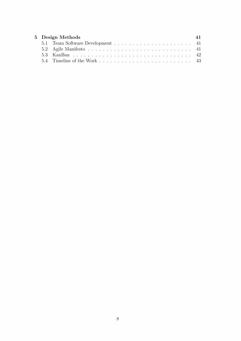
Vimar was founded in the far 1945 from an idea of Walter Viaro e FrancescoGusi, at Marostica, a small town near Bassano del Grappa. It produces electricaland electronical material, e.s for domestic series, domotic systems and multiplesockets. Company name is the union of initials of VIaro and MARostica.
Figure 1.1: Vimar headquarters
In the 15th of March 1968, Vimar registered the patent Sicury, a mechanismthat permits the automatic close of holes in the outlet when the plug is discon-nected. It permits security - increase, so the society has given it, free of charge,to all sector producers. In the 1975 Vimar has registered another patent, Bpresa,able to support italian plugs for 10 and 16 amps [10].My project has been done in the Electronical Research and Development office,which is a small part of a big company very well structured and rich in experience.
11

12
Chapter 2
Project Description
2.1 Purpose
Today, home appliances are becoming more and more Smart, now it’s time ofmaking them capable to communicate with the external world. Lots of housesuse an internal network to improve comfort and energy saving. It was realizeda device that makesd possible the communication from household appliance andthe external world and is called Smart Adapter; it will be described below.The goal of the project is to realize a communication interface betweenSmart Adapter and Domotic net. This realization is implemented for theVimar’s Home Network: By-Me R© , and the Smart Adapter designed by Elite srl.
2.2 Overview on the Project
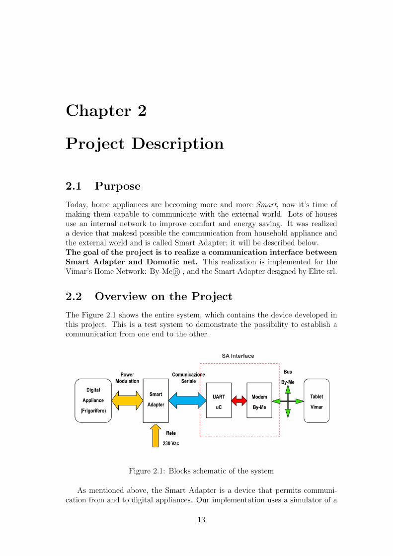
The Figure 2.1 shows the entire system, which contains the device developed inthis project. This is a test system to demonstrate the possibility to establish acommunication from one end to the other.
Figure 2.1: Blocks schematic of the system
As mentioned above, the Smart Adapter is a device that permits communi-cation from and to digital appliances. Our implementation uses a simulator of a
13
refrigerator that supports a simple Power Modulation protocol, and is made forthe purpose to create a test system. The Original project uses a particular PowerModulation called WR@P, here isn’t implemented at all, only physical layer isreproduced in full [1]. The role of Smart Adapter is to bring to the serial interfacethe Fridge Power Line messages and vice versa for serial ones. It’s clear that thisdevice must support the same communication protocol of the Digital Appliance.The Smart Adapter Interface is the target that project aims, here will be calledSA-Interface. The Hardware platform uses the same of a pre-existing Vimar de-vice. This is possible because the Smart Adapter has on board a serial RS-232,TTL standard port, also present on mentioned Vimar device, that already re-alized communication between serial and By-Me bus. The figure clearly showsthe communication blocks of the SA-Interface. The serial side uses the internalUART of the microcontroller. The Domotic bus side uses a standard circuit,called modem, which acts as receiver and transmitter. In addition to the projectfinalities, it is created a user interface on a Vimar’s tablet, based on Android,connected to the bus, to control the fridge or to receive messages from it.
2.3 Grid-Aware Networked Digital Appliance
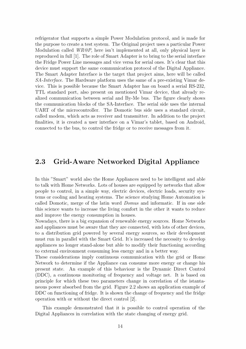
In this ”Smart” world also the Home Appliances need to be intelligent and ableto talk with Home Networks. Lots of houses are equipped by networks that allowpeople to control, in a simple way, electric devices, electric loads, security sys-tems or cooling and heating systems. The science studying Home Automation iscalled Domotic, merge of the latin word Domus and informatic. If in one sidethis science wants to increase the living comfort in the other it wants to reduceand improve the energy consumption in houses.Nowadays, there is a big expansion of renewable energy sources. Home Networksand appliances must be aware that they are connected, with lots of other devices,to a distribution grid powered by several energy sources, so their developmentmust run in parallel with the Smart Grid. It’s increased the necessity to developappliances no longer stand-alone but able to modify their functioning accordingto external environment consuming less energy and in a better way.These considerations imply continuous communication with the grid or HomeNetwork to determine if the Appliance can consume more energy or change hispresent state. An example of this behaviour is the Dynamic Direct Control(DDC), a continuous monitoring of frequency and voltage net. It is based onprinciple for which these two parameters change in correlation of the istanta-neous power absorbed from the grid. Figure 2.2 shows an application example ofDDC on functioning of fridge. It is shown the change of frequency and the fridgeoperation with or without the direct control [2].
This example demonstrated that it is possible to control operation of theDigital Appliances in correlation with the state changing of energy grid.
14
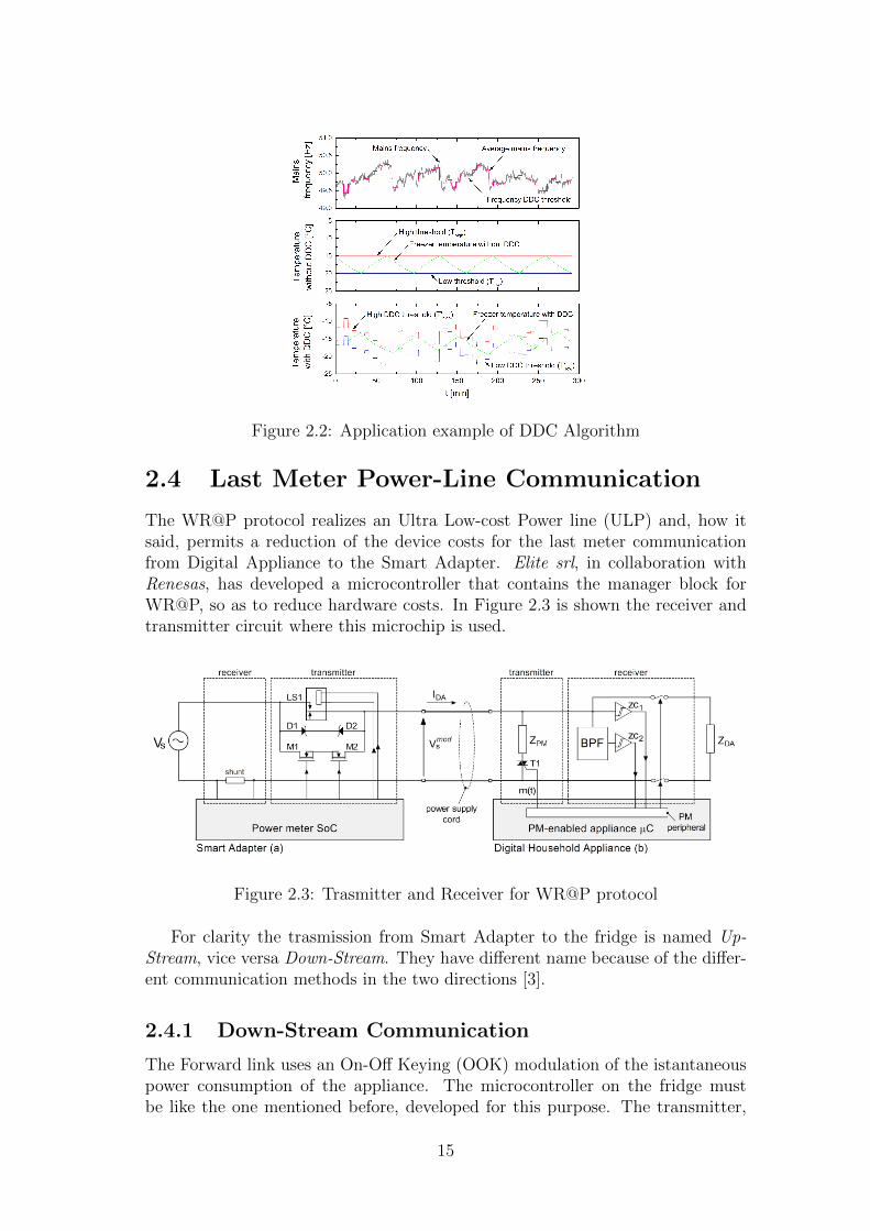
Figure 2.2: Application example of DDC Algorithm
2.4 Last Meter Power-Line Communication
The WR@P protocol realizes an Ultra Low-cost Power line (ULP) and, how itsaid, permits a reduction of the device costs for the last meter communicationfrom Digital Appliance to the Smart Adapter. Elite srl, in collaboration withRenesas, has developed a microcontroller that contains the manager block forWR@P, so as to reduce hardware costs. In Figure 2.3 is shown the receiver andtransmitter circuit where this microchip is used.
Figure 2.3: Trasmitter and Receiver for WR@P protocol
For clarity the trasmission from Smart Adapter to the fridge is named Up-Stream, vice versa Down-Stream. They have different name because of the differ-ent communication methods in the two directions [3].
2.4.1 Down-Stream Communication
The Forward link uses an On-Off Keying (OOK) modulation of the istantaneouspower consumption of the appliance. The microcontroller on the fridge mustbe like the one mentioned before, developed for this purpose. The transmitter,
15
into the appliance, is only made by a simple electric load, controlled throught atriac (T1), as shown in Figure 2.3.b. It is transmitted only one bit per period,this isn’t a limit, because the appliance state doesn’t change rapidly and requirestrasmission of few bytes. The receiver only needs a power meter, each bit isdecoded measuring the mean power absorbed by the appliance during each n-thcycle and compared with to an adaptive threshold, calculated as the weightedaverage over the k previous cycles’ power consumption.
2.4.2 Up-Stream Communication
In the reverse link, where Smart Adapter is the transmitter, data bits are en-coded with a Pulse Position Modulation (PPM), the transmitter generates someintentional, short and precise perturbations on zero crossing of the mains voltagewaveform. Information data are transmitted four times per period, to ensure thatat least one pulse is received. The multiplication of same bits is needed becausethe load of an alliance changes from one to another type. The perturbation isn’trevealed in the first quarter of power supply period if load is inductive and if itis capacitive isn’t revealed in the second quarter.The Transmitter provides two mosfets throught which a digital device controlsthe current flowing into two zener diodes. A relay activates the power supply ofthe branch, it is shown in Figure 2.3.a. Instead, a very cheap receiver is madeby a simple Analog Front-End, composed by a Band Pass Filter and a couple ofSchmitt-Triggers, connected to a pair of digital counters integrated into the PMperipheral on the microcontroller.
2.5 Smart Adapter
The Smart Adapter is a general purpose communication node located at theappliance outlet. It is a bridge between the WR@P protocol and the currenthome networks. The development of Smart household appliances has encounteredsome obstacles like the absence of common home-networking standards. Theappliance’s hardware and firmware are indipendent from these protocols, whichare managed by the Smart Adapter. In this way costs of communication, remotecontrolling and production testing of the appliances are not increased [4]. Thissolution, moreover, permits the development of new generation of Smart Plugs forthe communication with the grid and others household appliances plugged. Therole of the Smart Adapter Interface now is more clear, it is the missing piece forthe access to a particular Home Network, in this case Vimar standard: By-Me.Note that By-Me is, however, compatible with the Konnex Standard, so Vimar’sdomotic bus can integrate Konnex’s compatible products.The Serial access to the Smart Adapter is based on the standard RS 232, withTTL logic levels, thus to makes simple the interfacement of an other peripheral.
16

2.6 Konnex Bus
Konnex (KNX) is an open, royalted and platform-indipendent building automa-tion standard, approved by European an World certification bodies. It has beendeveloped by KNX Association, from some predecessors like BatiBUS, EuropeanInstallation Bus (EIB) and European Home System (EHS).The KNX Association is the creator and owner of KNX Technology, the membercompanies holders of rights for the certification of the interoperability of themproducts, that means, the capability to communicate to each other also fromdifferent manufacturer and different applications. KNX is the only standard con-trol for home and buildings worldmate, that presents guidelines for product andtraining centers.All manufacturer have to certificate compliance to ISO 9001 standard and alsowith the requirements of the European and International standard for Home andBuldings Electronic Systems [9]. An Example of a domotic system application isshown in Figure 2.4, where it’s visible, at the bottom, a controlling central andsome devices attached with it to the bus. It is possible to control lightings, plugs,home accesses and several other things.
Figure 2.4: An example of a Domotic Vimar net
This KNX protocol provides some specific communication media:
• Twisted Pair (KNX TP): transmission across separate bus cable, hierarchi-cally structured in lines and areas.
• Power Line (KNX PL): transmission on the existing mains network.• Radio Frequency (KNX RF): transmission via radio signals, devices can be
uni- or bidirectional.
17
• IP/Ethernet (KNX IP): can be used in conjunction with the ’KNXnet/IP’specifications, which allow the tunneling or routing of KNX frames encap-sulated in IP frame.
For the project here presented a Twisted Pair media is used as principal bus,it is the most widespred in home automation. For the communication with thetablet, that is reachable only from ethernet connection, is needed the KNX IPmedia, the specifications are held over in ’Tablet Interface on Home Network ’section.Note that, for simplicity, the Domotic bus here will be called only as ”bus”.
2.7 Smart Adapter Interface
This paragraph describes the Smart Adapter Interface, that is the aim of thisproject. As now is clear, it is the gateway from the serial port of the SmartAdapter and the KNX bus.The principal device function is interpreting messages from serial and bus, afterthat, are required other operations to convert data and build up the frame thatwill be brought to the opposite side. To work in this direction it is necessary thecompatibility with KNX devices, thus it should be positioned in a KNX systemlike all the others Vimar’s KNX certified peripherals. In this specific situationnot all the protocol rules are respected, because of the experimentation purpose,but the device is well integrable as mentioned above. The attention is focusedon data conversion, because standards have different rules for data format andencapsulation into frames. The bigger work is in take frame payload, deduce thetype and extract datas for convert them. After the conversion is constructed andsent the frame in the opposite side.
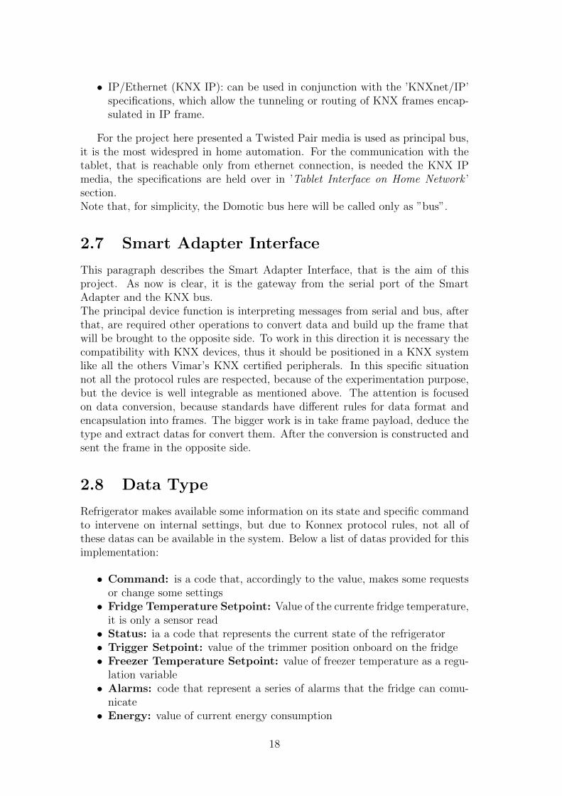
2.8 Data Type
Refrigerator makes available some information on its state and specific commandto intervene on internal settings, but due to Konnex protocol rules, not all ofthese datas can be available in the system. Below a list of datas provided for thisimplementation:
• Command: is a code that, accordingly to the value, makes some requestsor change some settings
• Fridge Temperature Setpoint: Value of the currente fridge temperature,it is only a sensor read
• Status: ia a code that represents the current state of the refrigerator• Trigger Setpoint: value of the trimmer position onboard on the fridge• Freezer Temperature Setpoint: value of freezer temperature as a regu-
lation variable• Alarms: code that represent a series of alarms that the fridge can comu-
nicate• Energy: value of current energy consumption
18

• Power: value of current istantaneous power consumption
Each variable is placed in a different frame and one value at time for eachones. This note is important to understand some choices in datas management.
19

20

Chapter 3
Project Results
3.1 Overall System
The system obtained from this project is shown in Figure 3.1, all parts composingthe system are described in this chapter.
Figure 3.1: Overview on the system
3.2 Hardware Structure
The hardware circuit is the same of a Vimar’s product already existing and totallycompatible. Figure 3.2 describes fundamental blocks, the structure is overallsimple. Follows a summary of importants hardware features.
• Microcontroller: ATMega 164P, 8-bit and RISC achitecture accompainedby In System Programming (ISP) and JTAG Interface. Some importantcharacteristics to underline:
– 16KB of In-System Self-programmable Flash program memory,
21
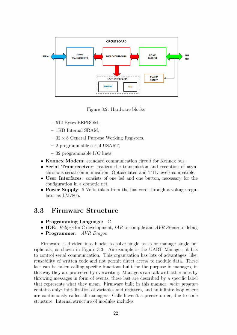
Figure 3.2: Hardware blocks
– 512 Bytes EEPROM,
– 1KB Internal SRAM,
– 32 × 8 General Purpose Working Registers,
– 2 programmable serial USART,
– 32 programmable I/O lines
• Konnex Modem: standard communication circuit for Konnex bus.• Serial Transreceiver: realizes the transmission and reception of asyn-
chronous serial communication. Optoisolated and TTL levels compatible.• User Interfaces: consists of one led and one button, necessary for the
configuration in a domotic net.• Power Supply: 5 Volts taken from the bus cord through a voltage regu-
lator as LM7805.
3.3 Firmware Structure
• Programming Language: C• IDE: Eclipse for C development, IAR to compile and AVR Studio to debug• Programmer: AVR Dragon
Firmware is divided into blocks to solve single tasks or manage single pe-ripherals, as shown in Figure 3.3. An example is the UART Manager, it hasto control serial communication. This organization has lots of advantages, like:reusability of written code and not permit direct access to module data. Theselast can be taken calling specific functions built for the purpose in manages, inthis way they are protected by overwriting. Managers can talk with other ones bythrowing messages in form of events, these last are described by a specific labelthat represents what they mean. Firmware built in this manner, main programcontains only: initialization of variables and registers, and an infinite loop whereare continuously called all managers. Calls haven’t a precise order, due to codestructure. Internal structure of modules includes:
22
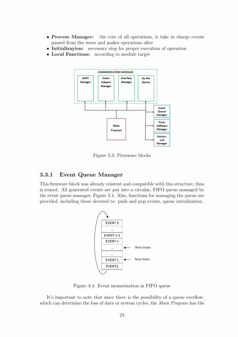
• Process Manager: the core of all operations, it take in charge eventspassed from the main and makes operations after
• Initializayion: necessary step for proper execution of operation• Local Functions: according to module target
Figure 3.3: Firmware blocks
3.3.1 Event Queue Manager
This firmware block was already existent and compatible with this structure, thusis reused. All generated events are put into a circular, FIFO queue managed bythe event queue manager, Figure 3.4. Also, functions for managing the queue areprovided, including those devoted to: push and pop events, queue initialization.
Figure 3.4: Event memorization in FIFO queue
It’s important to note that since there is the possibility of a queue overflow,which can determine the loss of data or system cycles, the Main Program has the
23
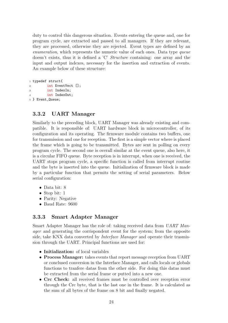
duty to control this dangerous situation. Events entering the queue and, one forprogram cycle, are extracted and passed to all managers. If they are relevant,they are processed, otherwise they are rejected. Event types are defined by anenumeration, which represents the numeric value of each ones. Data type queuedoesn’t exists, thus it is defined a ’C’ Structure containing: one array and theinput and output indexes, necessary for the insertion and extraction of events.An example below of these structure:
1 typedef struct{
2 int EventVect [];
3 int IndexIn;
4 int IndexOut;
5 } Event_Queue;
3.3.2 UART Manager
Similarly to the preceding block, UART Manager was already existing and com-patible. It is responsible of: UART hardware block in microcontroller, of itsconfiguration and its operating. The firmware module contains two buffers, onefor transmission and one for reception. The first is a simple vector where is placedthe frame which is going to be transmitted. Bytes are sent in polling on everyprogram cycle. The second one is overall similar at the event queue, also here, itis a circular FIFO queue. Byte reception is in interrupt, when one is received, theUART stops program cycle, a specific function is called from interrupt routineand the byte is inserted into the queue. Initialization of firmware block is madeby a particular function that permits the setting of serial parameters. Belowserial configuration:
• Data bit: 8• Stop bit: 1• Parity: Negative• Baud Rate: 9600
3.3.3 Smart Adapter Manager
Smart Adapter Manager has the role of: taking received data from UART Man-ager and generating the corrispondent event for the system; from the oppositeside, take KNX data converted by Interface Manager and operate their trasmis-sion through the UART. Principal functions are used for:
• Initialization: of local variables• Process Manager: takes events that report message reception from UART
or conclused conversion in the Interface Manager, and calls locals or globalsfunctions to tranfere datas from the other side. For doing this datas mustbe extracted from the serial frame or putted into a new one.
• Crc Check: all received frames must be controlled over reception errorthrough the Crc byte, that is the last one in the frame. It is calculated asthe sum of all bytes of the frame on 8 bit and finally negated.
24

• Build serial frames: compone the serial frame and use UART manger’sfunctions to put it into transmission buffer, if the transmission fail, it retriesin an other program cycle.
• Parse received serial frames: all bytes, first the header, are decodedto generate corresponding events for the system, if one or more bytes arewrong, message is ignored and no events are generated.
Events are generated in base of frame parsing, Figure 3.5 shows the generalframe structure. The header identifies frame charateristics, payload contains dataand checksum is the byte for error controlling.
Figure 3.5: General frame structure
One thing to underline in Smart Adapter functions, is the possibility to readthe istantaneously absorbed current and energy consumption. They are two im-portant parameters which allows controlling refrigerator operation. The SmartAdapter Manager generates periodically read requests for these variables.
3.3.4 By-Me Device Manager
This module contains all specific functions managing the SA Interface as By-Me bus connected device, it focus on device structure as specified by Konnexprotocol. Some functions are protocol standard, but some others are specifics ofthe device. It is the fundamental step for bus integration, without this module,the device can’t be recognized by other ones or by the Konnex Central. It isn’t areal Manager like the others, simply makes available the set of fuctions described.
3.3.5 Interface Manager
It is the central node for data exchange, indipendent from any protocol, it takesevents from the system and consequently, calls locals functions to process datato make them compatible with the destination protocol. In particular, when isreached the event signaling the arriving of a frame from Konnex bus, according todata type, is called function to convert this data. After that, the correspondingevent is placed in the queue, like in Figure 3.6.
In a different way are finalized datas coming from SA Manager, because ofthe absence of a proper ”manager” operating in Bus side. The By-Me Devicemodule, how specified above, hasn’t got an internal Process Manager, thus theInterface Manager has to manage the insertion of datas into Konnex frames. Todo this, it calls functions in By-Me module, these, permits transmission to lowerlayers of the stack and so on to phisical layer, see Figure 3.7.
An important part regards Alarms management. Because of variety of theseones on the household appliance, actives alarms are memorized in the Interface
25

Figure 3.6: Data exchange mechanism from By-Me Device to Smart AdapterManager
Figure 3.7: Data exchange mechanism from Smart Adapter Manager to By-MeDevice
Manager. Here is decided which alarms must be retransmitted, on the basis ofnew alarms and resetted ones. In the bus is sent one alarm a time, so only whenalarms state change, are resetted all and retransmitted updates ones.
3.3.6 Other Reused Blocks
Others reused Managers are described below:
• Timer Software Manager: on the basis of an hardware timer, it providesothers software timer, not fine like the first but useful for not precise tasks.For example used in the auto generated event for power consumption read.
• Buttons and Led Manager: it controls the button and the led for deviceconfiguration in konnex systems.
26
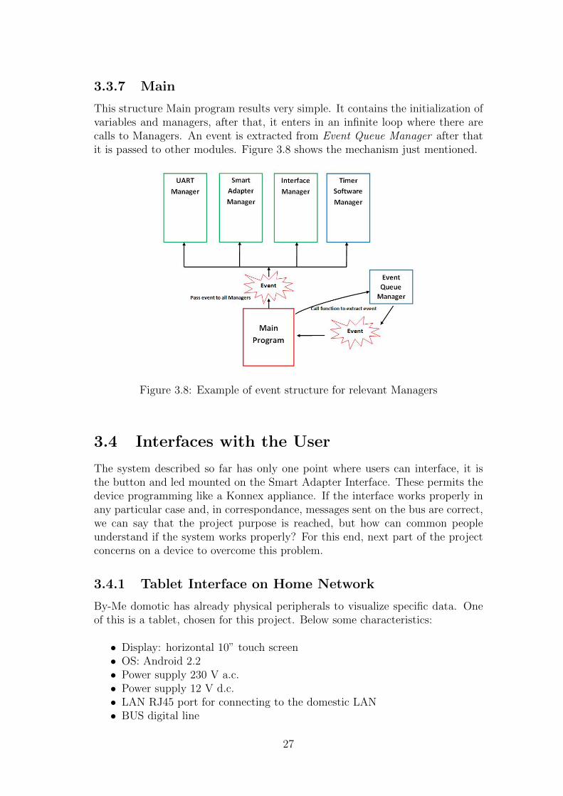
3.3.7 Main
This structure Main program results very simple. It contains the initialization ofvariables and managers, after that, it enters in an infinite loop where there arecalls to Managers. An event is extracted from Event Queue Manager after thatit is passed to other modules. Figure 3.8 shows the mechanism just mentioned.
Figure 3.8: Example of event structure for relevant Managers
3.4 Interfaces with the User
The system described so far has only one point where users can interface, it isthe button and led mounted on the Smart Adapter Interface. These permits thedevice programming like a Konnex appliance. If the interface works properly inany particular case and, in correspondance, messages sent on the bus are correct,we can say that the project purpose is reached, but how can common peopleunderstand if the system works properly? For this end, next part of the projectconcerns on a device to overcome this problem.
3.4.1 Tablet Interface on Home Network
By-Me domotic has already physical peripherals to visualize specific data. Oneof this is a tablet, chosen for this project. Below some characteristics:
• Display: horizontal 10” touch screen• OS: Android 2.2• Power supply 230 V a.c.• Power supply 12 V d.c.• LAN RJ45 port for connecting to the domestic LAN• BUS digital line
27

• N/O landing push button• SDHC port• USB port• Reset button
Figure 3.9: Vimar Tablet
It isn’t attached directly to the bus but comunicates with an ethernet routerwhich has the task to translate ethernet messages into Konnex ones. Tablet hasto use frame syntax for Konnex over IP systems.In this manner users can control the refrigerator from a remote position in domoticnet.
3.5 System Debug
The first problem encountered has affected serial communication, because of theinversion of signals on phisical transmission in the outlet of Smart Adapter. Onthe SA Interface serial signal is inverted again, in this way Microcontroller’sUART receives inverted levels than to expected. It is necessary an inverter circuitto adjust the link, this one is made only by two logical inverter ports, placed inboth communication directions. Figure 3.9 shows this simple circuit, it is visiblealso in Figure 3.1 at the beginning of the chapter.
Figure 3.10: Inverter circuit for serial communication
28

Firmware debug is done with the support of AVR Studio and the AVR Dragonprogrammer using JTAG JointTestActionGroup port, provided in this micro-controller. JTAG permits in circuit debugging, so is simple to determine whereproblems are located an how resolve them. In addition, using a By-Me to USBconverter and an appropriate software is possible to intercept frames on the busand control the accuracy of messages translated by the Smart Adapter Interface.No relevant problems was encountered, only small errors was detected in the code.
29

30

Chapter 4
Android Interface Application
User can interface to refrigerator through a tablet, Vimar product. It is a flexibledevice which can be used for many applications. For the purpose is designedan application permitting the household appliance controls, called RefirgeratorInterface. Below some development details:
• IDE: Eclipse Java, combined with Android Development Tool ADT pluginand Java Development Kit JDK
• Software Development Kit (SDK): 2.1 with API 7
• Operative System: Ubuntu 12.04, 32 bit
• Android Programming Method: Native Android, xml files and javaclasses
4.1 KNX over IP
Tablet results connected to the bus through an ethernet to Konnex converter, isunderstandable that it can communicate using ethernet protocol. Konnex maybe used also in TCP/IP communication, for this purpose a research group ofWien University has developed an open source library called Calimero. It is aGNU GPL (General Public License), so it is free like any extention and programdeveloped with it. Calimero provides functions to manage Konnex over IP com-munication, for example, it monitors link with another device (in this case therouter). Below are listed the instructions to open communication with the router:
1 public int Open_Communication (String routerIP){
2
3 int result = 0; // Variabile per ritorno risultato apertura connessione
4
5 try{
6 netLinkIP = new KNXNetworkLinkIP(KNXNetworkLinkIP.TUNNEL,
7 new InetSocketAddress(InetAddress.getByName("192.168.0.100"),0),
8 new InetSocketAddress(InetAddress.getByName(routerIP),
9 KNXnetIPConnection.IP_PORT),false, new TPSettings(false));
10 }
31
11 catch (KNXLinkClosedException e){
12 e.printStackTrace();
13 result = -1;
14 }
15
16 // ...
It appears evident the IP addressing of router, and tunnelling option to specifyprotocol incapsulation. In the software are necessary only opening and closing ofcommunication, any other operation on ethernet link is made by the library.
4.2 Application Structure
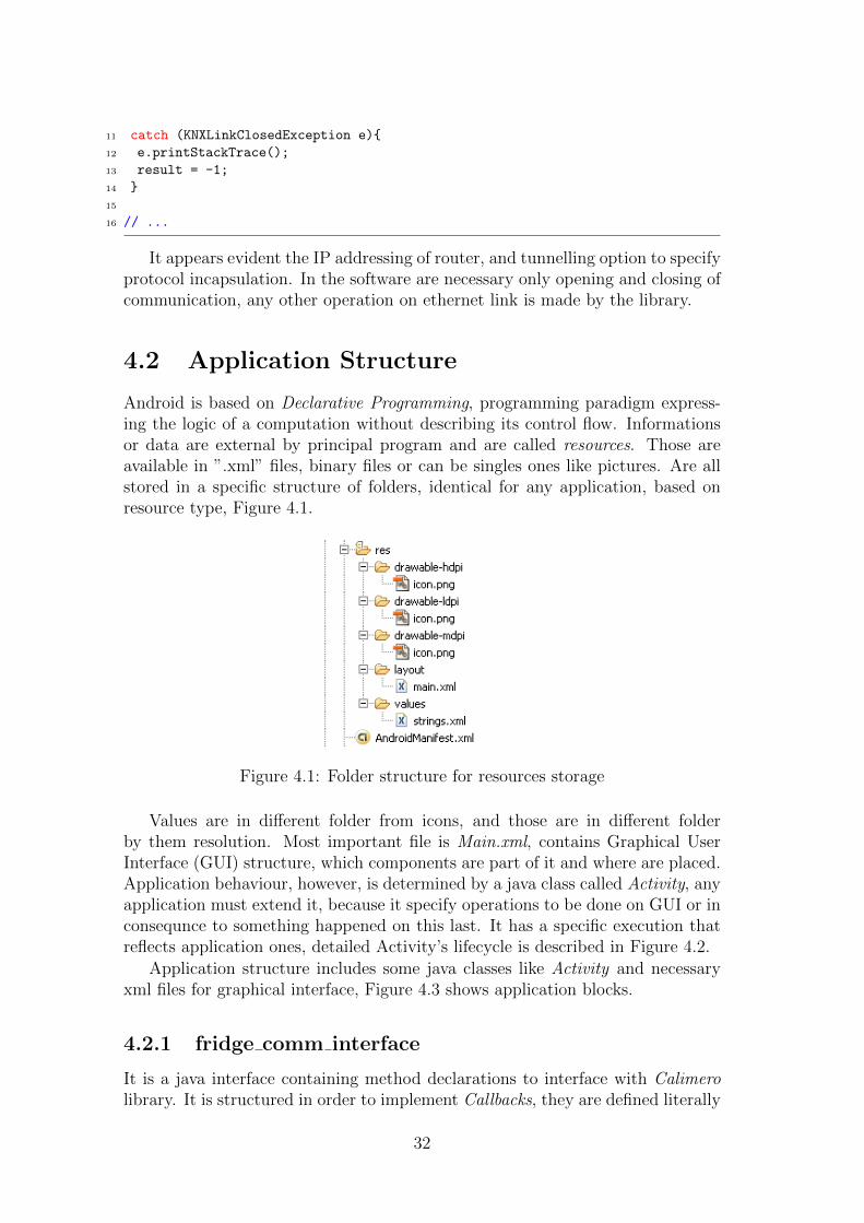
Android is based on Declarative Programming, programming paradigm express-ing the logic of a computation without describing its control flow. Informationsor data are external by principal program and are called resources. Those areavailable in ”.xml” files, binary files or can be singles ones like pictures. Are allstored in a specific structure of folders, identical for any application, based onresource type, Figure 4.1.
Figure 4.1: Folder structure for resources storage
Values are in different folder from icons, and those are in different folderby them resolution. Most important file is Main.xml, contains Graphical UserInterface (GUI) structure, which components are part of it and where are placed.Application behaviour, however, is determined by a java class called Activity, anyapplication must extend it, because it specify operations to be done on GUI or inconsequnce to something happened on this last. It has a specific execution thatreflects application ones, detailed Activity’s lifecycle is described in Figure 4.2.
Application structure includes some java classes like Activity and necessaryxml files for graphical interface, Figure 4.3 shows application blocks.
4.2.1 fridge comm interface
It is a java interface containing method declarations to interface with Calimerolibrary. It is structured in order to implement Callbacks, they are defined literally
32

Figure 4.2: Activity lifecycle
Figure 4.3: Android Application Structure
as a piece of code passed as argument to an other code. In this case, they are im-plemented as functions, defined in java interface but implemented in applicationActivity. Their task is to make some operations on Activity’s scope on precisemoments indicated by Fridge Communicator. Figure 4.4 shows this intricatedmechanism.
33

Below an extract from the module code.
1 public interface fridge_comm_interface {
2 //- ABSTRACT FUNCTIONS -
3 public void on_Temp_FR_Setpoint_recv(String value_arrived);
4 public void on_Status_recv(byte value_arrived);
5 public void on_Trimmer_Setpoint_recv(String value_arrived);
6 public void on_Temp_FZ_recv(String value_arrived);
7 public void on_Alarms_recv(byte value_arrived);
8 public void on_Energy_recv(String value_arrived);
9 public void on_Power_recv(String value_arrived);
10 }
Figure 4.4: Callback functioning
4.2.2 Fridge Communicator
It is a java class responsible of communication with the bus, it manages ethernetlink with Calimero library methods. It implements Thread interface, because isnecessary its backgroud running at the same time of main Android Activity. Athread is one part of a process, obtained breaking it into small pieces, executedconcurrently by mono - or multi-processor systems. Here, the overall processis the application and smaller task is Refrigerator Interface. Figure 4.5 describehow thread are used. In the class are defined some objects belonging to Calimero,used to manage communication with router. One of this is used to implementcallbacks for thread, so when a message arrives from bus the callback functionsignals it to thread, this brings message and pass it to activity through callbacksmentioned on precedent paragraph. Below run method of thread, is immediatethe presence of an infinite loop maintaining thread executed also when it hasnothing to do.
1 public void run(){
2 callb_runnable = new Runnable(){
3 public void run(){
4 Source_Parser(); // chiama callbacks
5 }
6 };
7
8 while(true){
34

9 try{
10 sleep(100);
11 }
12 catch (Exception e) {
13 e.printStackTrace();
14 }
15 }
16 }
Figure 4.5: Thread functioning
Note that inside the function is defined a runnable object, is similar to threadbut this class must be extended not implemented by an other class. This objectcan be called with specific functions differently from thread. More important isSource Parser() method, has to parse messages and call respective callback. Fol-lowing code shows class constructor, in it are visible: mentioned call instructionand listener object to capture messages from the bus.
1 public Fridge_Communicator (fridge_comm_interface arg0){
2
3 callb_communic = arg0;
4 handler = new Handler();
5 listener = new NetworkLinkListener() {
6
7 public void indication(FrameEvent arg0) {
8
9 frame = (tuwien.auto.calimero.cemi.CEMILData) arg0.getFrame();
10 frame_payload = frame.getPayload();
11 source = (GroupAddress)frame.getDestination();
12 subGroup = source.getSubGroup8();
13
14 handler.post(callb_runnable); // <- RUNNABLE
15 }
16
17 public void linkClosed(CloseEvent arg0) {
18 }
19
20 public void confirmation(FrameEvent arg0) {
35

21 }
22 };
23 }
4.2.3 RefrigeratorInterfaceActivity
It is java class from which application take its behaviour, implements fridge comminterface.java and extends Activity class. Class implementation is needed from
callback structure, within code are implemented methods of the interface in orderto define callbacks operations towards graphical interface. Follows definition codefor some callback:
1 public void on_Trimmer_Setpoint_recv(String value_arrived) {
2 textVisual.setText("Trimmer UPDATE");
3 tempFR.setText(value_arrived);
4 }
5
6 public void on_Temp_FZ_recv(String value_arrived) {
7 textVisual.setText("Temp FZ UPDATE");
8 tempFZ.setText(value_arrived);
9 }
10
11 public void on_Temp_FR_Setpoint_recv(String value_arrived) {
12 textVisual.setText("Temp FR UPDATE");
13 }
14
15 public void on_Status_recv(byte value_arrived) {
16 textVisual.setText("Status UPDATE");
17 }
18
19 //...
When data arrives it must be communicated to the user, so firstly is displayeda toast (box dialog containing a text), with the instruction:
1 textVisual.setText("Trimmer UPDATE");
after that are made all other operations needed by data type. For example toset new temperature received is used the instruction below:
1 tempFR.setText(value_arrived);
where value arrived is new data to be updated. Very interesting part concernsrefrigerator doors alarm, simply described as a function that sets an animationon tablet screen. In background a thread runs to compose the animation fromsuccessives images, it is at all effects a resource for the application, in next codeextract are shown mentioned instructions.
1 public void on_Alarms_recv(byte value_arrived) {
2
36
3 textVisual.setText("Alarm received: " + (int)value_arrived);
4
5 if(value_arrived == 0){ // Ricevuto reset allarmi
6 animation_freezer.stop();
7 freezer_warning_active = false;
8 fridge_warning_active = false;
9
10 fridge_status_visualizer.setImageResource(R.drawable.ok);
11 fridge_status_visualizer.setBackgroundResource(R.drawable.porta_ok);
12
13 animation_freezer = (AnimationDrawable) fridge_status_visualizer.getBackground();
14 animation_freezer.start();
15 textVisual.setText("Reset Alarms Received");
16
17 }
18 else if(value_arrived == 3){ // Ricevuto allarme porta frigo
19 fridge_warning_active = true;
20 animation_freezer.stop();
21 if(freezer_warning_active == true){
22 //calls to resources
23 fridge_status_visualizer.setImageResource(R.drawable.warning);
24 fridge_status_visualizer.setBackgroundResource(R.drawable.porta_frigo_freezer);
25 //thread set
26 animation_freezer = (AnimationDrawable) fridge_status_visualizer.getBackground();
27 animation_freezer.start();
28 }
29 else{
30 fridge_status_visualizer.setImageResource(R.drawable.warning);
31 fridge_status_visualizer.setBackgroundResource(R.drawable.porta_frigo);
32 animation_freezer = (AnimationDrawable) fridge_status_visualizer.getBackground();
33 animation_freezer.start();
34 }
35 }
36
37 //...
Regarding to activity life, are necessary functions describing operations to doin these situations. OnCreate() function point out on what to do on applicationstart, in the opposite OnDestroy() for application exit. Finally the activity mustcatch any possible user interaction with the application, in this case it can pushsome buttons predisposed to send messages towards fridge. These are like call-back, an example is visible in following code:
1 public void onButtonSetTempFRSetpointClick (View view){
2
3 int value = 0;
4 String strvalue;
5 int result = 0;
6 String output = "Setpoint Sent";
7 // aggancio oggetto spinner
8 Spinner spinner3 = (Spinner)findViewById(R.id.spinner3);
9 // prelevo il valore all’interno
10 strvalue = spinner3.getSelectedItem().toString();
11
12 // Converte stringa in intero
37

13 value = Integer.parseInt(strvalue);
14
15 result = fridge_comm.set_Temp_FR_Setpoint(value);
16
17 if(result == -1)
18 output = "Setpoint Not Sent";
19 else if(result == -2)
20 output = "Link Down";
21
22 // ...
4.3 Graphic Interface
Graphical interface is composed by these principal files:
• AndroidManifest.xml : contains all information about the graphical interface
• activity refrigerator interface.xml : also mentioned as main.xml, containsdetailed description of all parts of GUI
• String.xml : includes definition all stings or variables
• Styles.xml : describes application theme
General aspect is visible in Figure 4.6, on the left there is data visualization,on the right an animation to communicate if there are fridge doors opened. Figure4.7 shows in detail how alarms can be comunicated, for example for fridge door.
Figure 4.6: Refrigerator Interface Application
38
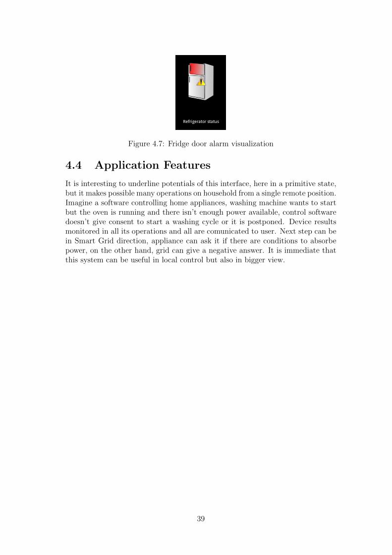
Figure 4.7: Fridge door alarm visualization
4.4 Application Features
It is interesting to underline potentials of this interface, here in a primitive state,but it makes possible many operations on household from a single remote position.Imagine a software controlling home appliances, washing machine wants to startbut the oven is running and there isn’t enough power available, control softwaredoesn’t give consent to start a washing cycle or it is postponed. Device resultsmonitored in all its operations and all are comunicated to user. Next step can bein Smart Grid direction, appliance can ask it if there are conditions to absorbepower, on the other hand, grid can give a negative answer. It is immediate thatthis system can be useful in local control but also in bigger view.
39

40
Chapter 5
Design Methods
5.1 Team Software Development
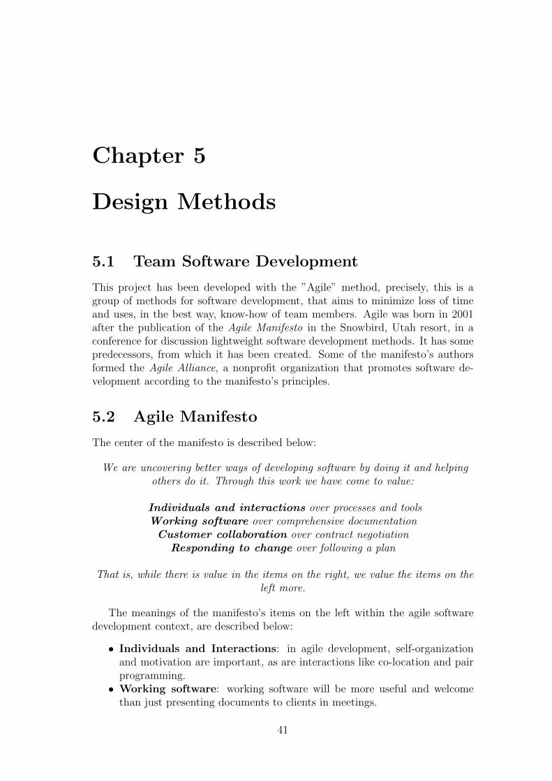
This project has been developed with the ”Agile” method, precisely, this is agroup of methods for software development, that aims to minimize loss of timeand uses, in the best way, know-how of team members. Agile was born in 2001after the publication of the Agile Manifesto in the Snowbird, Utah resort, in aconference for discussion lightweight software development methods. It has somepredecessors, from which it has been created. Some of the manifesto’s authorsformed the Agile Alliance, a nonprofit organization that promotes software de-velopment according to the manifesto’s principles.
5.2 Agile Manifesto
The center of the manifesto is described below:
We are uncovering better ways of developing software by doing it and helpingothers do it. Through this work we have come to value:
Individuals and interactions over processes and toolsWorking software over comprehensive documentationCustomer collaboration over contract negotiation
Responding to change over following a plan
That is, while there is value in the items on the right, we value the items on theleft more.
The meanings of the manifesto’s items on the left within the agile softwaredevelopment context, are described below:
• Individuals and Interactions: in agile development, self-organizationand motivation are important, as are interactions like co-location and pairprogramming.
• Working software: working software will be more useful and welcomethan just presenting documents to clients in meetings.
41

Figure 5.1: KanBan, board containing project tasks
• Customer collaboration requirements cannot be fully collected at thebeginning of the software development cycle, therefore continuous customeror stakeholder involvement is very important.
• Responding to change agile development is focused on quick responsesto change and continuous development.
Below, twelve principles underlie the Agile Manifesto:
1. Customer satisfaction by rapid delivery of useful software2. Welcome changing requirements, even late in development3. Working software is delivered frequently (weeks rather than months)4. Working software is the principal measure of progress5. Sustainable development, able to maintain a constant pace6. Close, daily co-operation between business people and developers7. Face-to-face conversation is the best form of communication (co-location)8. Projects are built around motivated individuals, who should be trusted9. Continuous attention to technical excellence and good design
10. Simplicity- The art of maximizing the amount of work not done - is essential11. Self-organizing teams12. Regular adaptation to changing circumstances
5.3 KanBan
An useful instrument to accompain Agile is the KanBan, used in this project asfundamental tool. Big tasks are broken down into smallest ones and placed into aposter, that have the duty to create a global vision on the overall project. Figure5.1 shows an example of the poster.
Periodically are generated these tasks that someone will take them in charge,strictly connected to the personal Kow-How. This method provide a daily meet-ing with team members, of about five minutes, where anyone must explain the
42

progress of his task and if some problems have arisen. The purpose is keep updateall members on the actual state of the project.
5.4 Timeline of the Work
Below are described the steps or tasks programmed during the project, from thestart to the end:
1. Study of the Elite product (Fridge Simulator and Smart Adapter)
2. Draft of the project
3. Study of the basics of By-Me and Konnex
4. Learning the operation of hardware of previous Vimar’s device
5. Drawing up documentation on project
6. Drawing up firmware Code
7. Firmware debug
8. Study of the basics of Android
9. Android application develop
10. System funtioning debug
Few words are necessary to point out the preparation of documentation on theproject. Before starting any operation, were written three levels of documentationdescribing what will be done and how, they are described below:
• Functional Specifications: describes what the device can done, withouttechnical details
• Technical Specifications: describes the technology used, interface tousers, system architecture and eventuals insights
• Detail Specifications: describes, in this case, the firmware in detail
This operating method allow good conduct of the project, from the start tothe end, this doesn’t mean the absence of problems but when they comes youhave something more to solve them.
Below the summary on the stage at Vimar:
• Number of hours provided by the University: 180
• Number of hours done: 308
• Start date: 3/9/2012
• End date: 5/11/2012
• Number of days: 40
43

44

Bibliography
[1] [ A. Ricci, B. Vinerba, E. Smargiassi, V. Aisa, I. De Munari, V. Cascio,P. Ciampolini ] ”Wr@p: the Last Meter Technology for Energy-Aware Net-worked Smart Appliances”, 3rd Workshop on Power Line communications,October 2009, Udine, ITALY
[2] [ A. Ricci, B. Vinerba, E. Smargiassi, V. Aisa, I. De Munari, V. Cascio,P. Ciampolini ] ”Power-Grid Load Balancing by Using Smart Home Appli-ances”, PM papers
[3] [A. Ricci, V. Aisa, I. De Munari, V. Cascio, P. Ciampolini ] ”Implementa-tion and Test of a Power-Line based Communication System for ElectricalAppliances Networking”, PM papers
[4] [ A. Ricci, Student Member, IEEE, V. Aisa, I. De Munari, V. Cascio, P.Ciampolini ] ”Electrical Appliances Networking: an Ultra-Low Cost Solutionbased on Power-Line Communication”, PM papers
[5] [ A. Ricci, B. Vinerba, E. Smargiassi, V. Aisa, I. De Munari, V. Cascio, P.Ciampolini ] ”Design and Test of a Microcontroller Peripheral for Grid-AwareNetworked Digital Appliances”, 3rd Workshop on Power Line communica-tions, October 2009, Udine, ITALY
[6] [Brian Kernighan and Dennis Ritchie, 1988] ”The C Programming Lan-guage”, second edition
[7] [R.Bruni, A. Corradini, V. Gervasi, 2009] ”Programmazione in JAVA”, ed.Apogeo
45

46
Sitography
[8] http://www.knx.it
[9] http://www.knx.org
[10] http://www.vimar.com
[11] http://www.calimerong.org
[12] http://www.wikipedia.it
[13] http://www.agilemanifesto.org
47