Relays and Resistors Mike Battaglia Will Mills. Relays A relay is a special kind of switch that is...
27
Relays and Resistors Mike Battaglia Will Mills
-
Upload
scot-mathews -
Category
Documents
-
view
228 -
download
0
Transcript of Relays and Resistors Mike Battaglia Will Mills. Relays A relay is a special kind of switch that is...

Relays and Resistors
Mike Battaglia
Will Mills

Relays• A relay is a special kind of
switch that is electrically actuated.
• A relay can be thought of as another use for an inductor. Rather than using the inductor coil to resist changes in current, the magnetic field produced is used to pull a magnetically charged, spring loaded plate from one contact to another, opening or closing the switch.
• Relays were invented by Joseph Henry in 1835. This is the same Henry whose name has become the unit for inductance.
An “ice cube” style AC coil DPDT relay

Switching Arrangements• Relays have the same
switching arrangements that switches do (SPST, SPDT, DPDT, etc).
• The diagram to the left shows some common relay arrangements, along with their respective circuit symbols.
• Note that the relay symbol is actually two parts; the first part is the symbol for an inductor with two parallel lines next to it, and the second part is a separate circuit representing the switch itself. The two circuits will not be connected.

Relays – Terms
• The voltage needed to activate a given relay is referred to as the excitation voltage.
• The voltage used to activate a given relay may be either AC or DC. A relay with an AC coil will need an AC voltage, a DC coil will need DC voltage.
• The coil resistance is the resistance limiting the current flow through the coil. For a DC coil, this will the only factor in determining the current. For an AC current, the inductance of the coil itself, combined with the coil resistance, will be used to determine the current.

How do relays work?
• There are three basic kinds of relays that each work in different ways: Mechanical relays, reed relays, and solid-state relays.
• Mechanical relays, which are older, are designed for high currents (2 A to 15 A), but take a relatively long time to operate (10-100 ms).
• Reed relays are designed for moderate currents (500 mA to 1 A) and moderately fast switching (0.2-2 ms). Reed relays are DC-actuated only, and are generally limited to SPST switching.
• Solid-state relays are newer, and use semiconductors to operate. They come with a wide range of current ratings (from the microamp range up to 1500 A), and have switching speeds of 1 – 100 ns. Solid state relays are also generally limited to SPST switching.
• Some relays are designed to be Normally Open (NO), and others Normally Closed (NC).

• A current sent through the coil magnet acts to pull a flexible, spring-loaded, conductive plate from one switch contact to another.
• Many mechanical relays come equipped with a “latching” feature that keeps the switch in its last set position until another pulse is applied.
• Mechanical relays come in two main varieties: Miniatureand subminiature relays.
Mechanical Relays
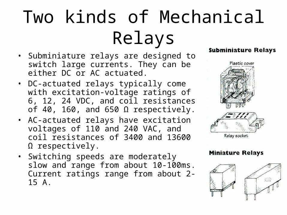
Two kinds of Mechanical Relays
• Subminiature relays are designed to switch large currents. They can be either DC or AC actuated.
• DC-actuated relays typically come with excitation-voltage ratings of 6, 12, 24 VDC, and coil resistances of 40, 160, and 650 Ω respectively.
• AC-actuated relays have excitation voltages of 110 and 240 VAC, and coil resistances of 3400 and 13600 Ω respectively.
• Switching speeds are moderately slow and range from about 10-100ms. Current ratings range from about 2-15 A.

Two kinds of Mechanical Relays
• Miniature relays are designed to be more sensitive than subminiatures and work with lower-level currents. They are almost always DC-actuated, but they may be designed to switch AC currents.
• They generally come with excitation voltages of 5, 6, 12, and 24 VDC.
• Their coil resistances range from 50 to 3000 Ω.

Reed Relays• In a reed relay, two metal strips (reeds) act
as the contacts themselves.• They are placed in a glass capsule that is
surrounded by a coil magnet. When current is sent through the coil, the resulting magnetic field forces the reeds together, closing the switch.
• The switching time is faster than mechanical relays at around 0.2 – 2 ms.
• The reeds are sometimes wet with mercury to eliminate contact bounce. The low resistance of mercury means that the relay can work with lower voltage signals.
• Reed relays are DC-actuated only, and can only be used in an SPST arrangement. They are often made for PCB mounting.
• They are designed to switch low-level currents, and come with excitation voltages of 5, 6, 12, and 24 VDC. Their coil resistances range from 250-2000 Ω.
• Reed Relays can be easily damaged by power surges.

Solid-State Relays• A solid-state relay switches states by
applying the excitation voltage to a semiconductive junction. There is no coil.
• They are the newest kind of relay invented. They have extremely fast switching speeds in the nanosecond range, and can work with currents as low as a few microamps or as high as 1.2 kA.
• There are no moving parts, so contact wear isn’t an issue.
• These devices often have high “on” resistances, are often more finicky to work with, and can blow out much more easily than electromechanical relays.
• Examples of Solid-State relays include transistors and thyristors.
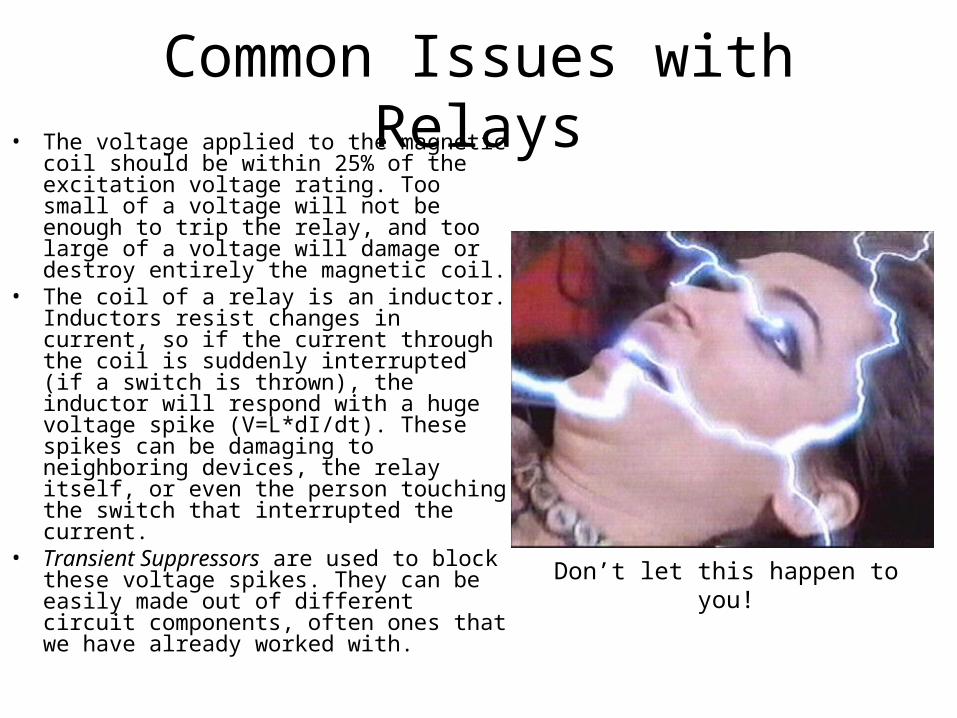
Common Issues with Relays• The voltage applied to the magnetic coil
should be within 25% of the excitation voltage rating. Too small of a voltage will not be enough to trip the relay, and too large of a voltage will damage or destroy entirely the magnetic coil.
• The coil of a relay is an inductor. Inductors resist changes in current, so if the current through the coil is suddenly interrupted (if a switch is thrown), the inductor will respond with a huge voltage spike (V=L*dI/dt). These spikes can be damaging to neighboring devices, the relay itself, or even the person touching the switch that interrupted the current.
• Transient Suppressors are used to block these voltage spikes. They can be easily made out of different circuit components, often ones that we have already worked with.
Don’t let this happen to you!
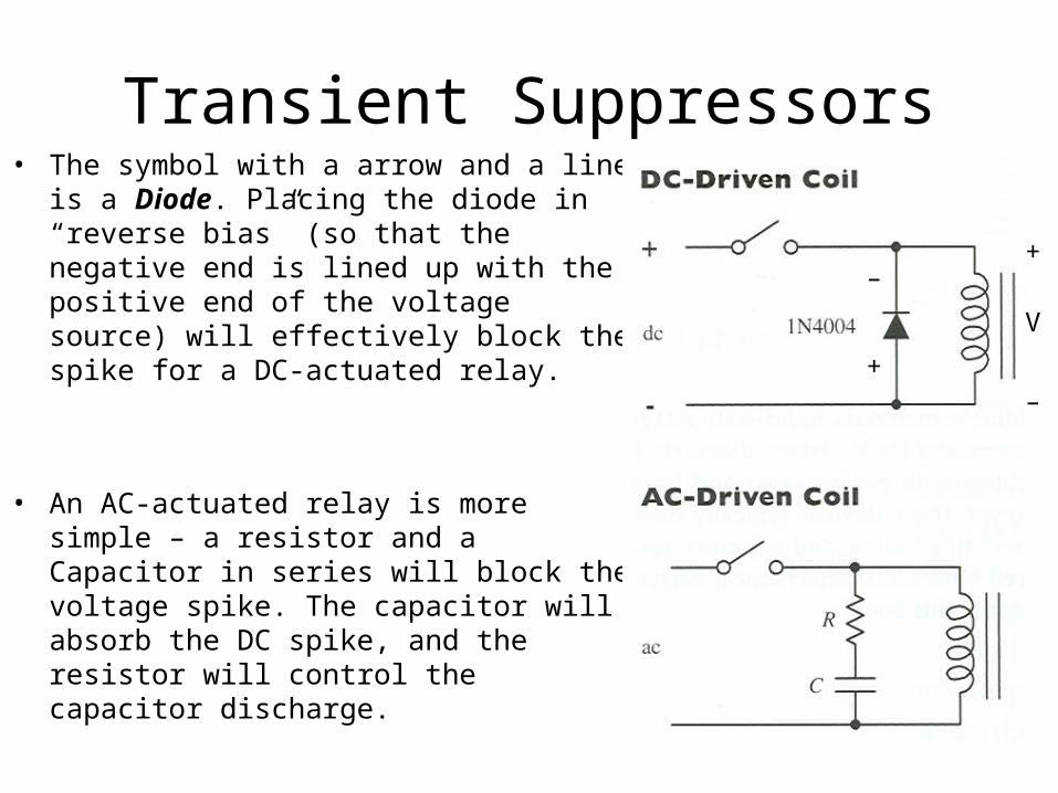
Transient Suppressors• The symbol with a arrow and a line is a
Diode. Placing the diode in “reverse bias” (so that the negative end is lined up with the positive end of the voltage source) will effectively block the spike for a DC-actuated relay.
• An AC-actuated relay is more simple – a resistor and a Capacitor in series will block the voltage spike. The capacitor will absorb the DC spike, and the resistor will control the capacitor discharge.
–
+
+
–
V

Examples of Relay-Based Circuits
• When the switch in the DC-actuated circuit is thrown, the relay pull the contact downward and close the lower circuit. This means that the lower bulb will light. When the switch is opened, the relay will relax, and the upper bulb will light again. The diode blocks the voltage spike.
• The AC-actuated circuit behaves the same way that the preceding circuit does. The only difference is in the transient suppressor. When the switch is thrown or opened, the voltage spike will be intercepted by the capacitor, which will slowly discharge through the resistor.

Resistors• A resistor is a simple electrical
device that serves to reduce current flow and lowers voltage levels in a circuit.
• They are commonly used to set signal levels, act as damping agents in oscillators, and provide feedback networks for amplifiers.
• Resistors can be of either fixed or variable resistance. Some resistors are dependant on an external light or heat source.
A 30-ohm Carbon Film Resistor

How do resistors work?• An electric current flows
through the resistor. Some of the electrons collide with atoms inside, transferring their kinetic energy into atomic vibrations.
• These vibrations are converted into heat energy and dissipate into surrounding air molecules (or a heat sink).
• This basically serves to limit the current through the resistor.
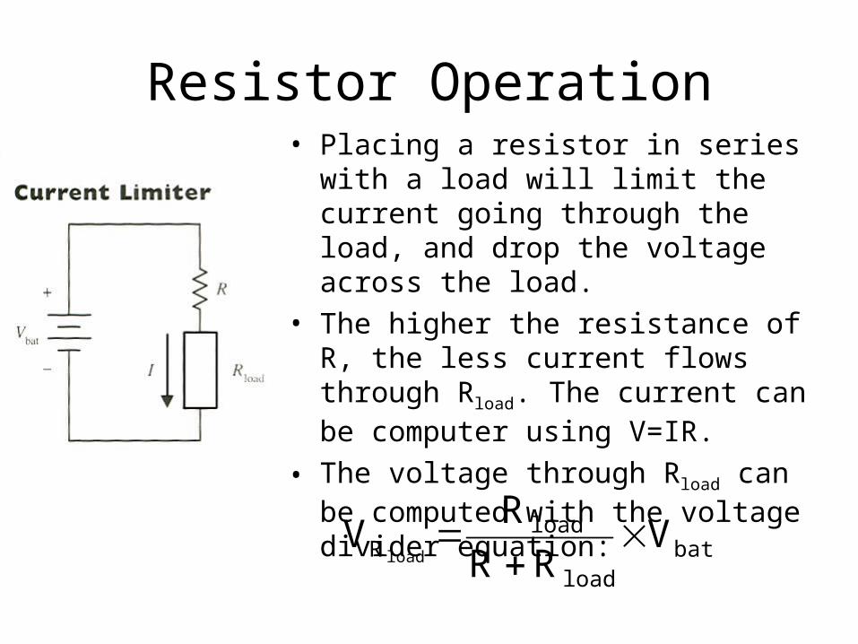
Resistor Operation• Placing a resistor in series with a load
will limit the current going through the load, and drop the voltage across the load.
• The higher the resistance of R, the less current flows through Rload. The current can be computer using V=IR.
• The voltage through Rload can be computed with the voltage divider equation:
batload
loadR V
RRR
Vload

Types of Resistors• A carbon film resistor is one of the
most popular resistors used today.• A carbon film is deposited onto a small
ceramic cylinder. A small spiral groove cut into the film controls the amount of carbon between the leads, which controls the resistance.
• Carbon film resistors are known for excellent reliability, solderability, and a high tolerance to noise, moisture, and heat.
• Typical power ratings range from ¼ to 2 W, and resistances range from 10 Ω to 1 MΩ, with tolerances around 5%.
A 2.7k Ω, ½ W, 5% tolerance, carbon film resistor

Types of Resistors• Carbon composition resistors are
made from a mixture of carbon powder and a glue-like binder. To increase the resistance, less carbon is added.
• These resistors are known for being predictable, with low inductance and low capacitance.
• Power ratings range from ⅛ to 2 W. Resistances range from 1 Ω to100 MΩ, with tolerances of 5%. A 4.3kΩ, ¼ W, 5%
tolerance, carbon composition resistor

Types of Resistors• Metal-Oxide resistors use a
ceramic core coated with a metal oxide film.
• These resistors are known to be very stable during high-temperature operation.
• They contain a special paint on their outer surfaces making them resistant to flames, solvents, heat, and moisture.
• Resistances range from 1 Ω –200 kΩ, with tolerances of 5%. Various metal oxide resistors

Types of Resistors• Precision metal film resistors are
known for being very accurate and ultra-low noise.
• It is made from a ceramic substrate coated with a metal film, encased in an epoxy shell.
• These are often used in high-precision devices, such as test instruments, D-A and A-D converters, and A/V devices.
• Resistances range from about10 Ω to 2 MΩ, with power ratings from ⅛ to ½ W, and tolerances of 1%.
Various metal film resistors
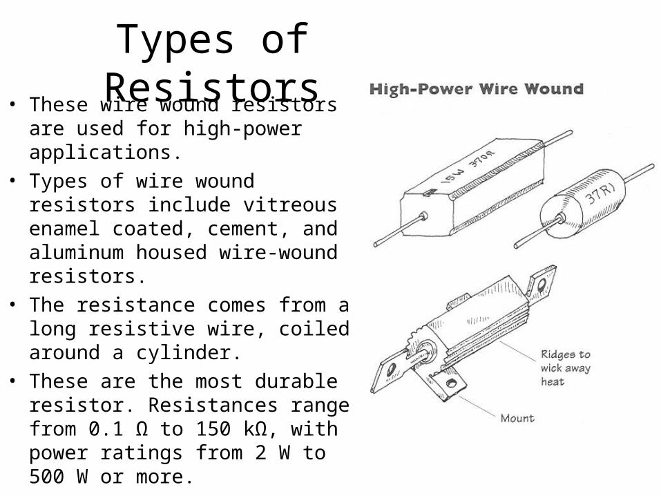
Types of Resistors• These wire wound resistors are
used for high-power applications.• Types of wire wound resistors
include vitreous enamel coated, cement, and aluminum housed wire-wound resistors.
• The resistance comes from a long resistive wire, coiled around a cylinder.
• These are the most durable resistor. Resistances range from 0.1 Ω to 150 kΩ, with power ratings from 2 W to 500 W or more.

Types of Resistors• These two resistors are special
types that vary the resistance based on an external heat or light source.
• Photoresistors are often made from semiconductive materials. Increasing the light level decreases the resistance.
• Thermistors are temperature sensitive resistors. Increasing the temperature decreases the resistance, in most cases.


• Two resistors may have the same resistance values, but different power ratings (wattage ratings).
• Resistors with higher power ratings can dissipate heat generated by a current more effectively.
• To determine what power rating your resistor should have, use the equation
• This is the minimum power rating necessary for the resistor to survive without melting
Power Ratings
.RIP 2Needed higher power rating!!
melting

Variable Resistors
• A special case of resistor is a variable resistor.• These resistors can be adjusted to set the resistance to a user-defined
value.• Potentiometers, rheostats, and trimmers are all different types of variable
resistors.• Potentiometers and rheostats are both essentially the same thing. They are
adjusted by a knob and can be used, for example, as a volume control.• Potentiometers are generally used for low-level DC electricity, and rheostats
are used for high-power AC electricity. They are designed for frequent adjustment.
• Trimmers are designed to be adjusted infrequently, and usually come with PCB-mounting pins. They are used for fine-tuning circuits, and are usually hidden.

Variable Resistors
• Variable resistors can be linear-tapered and nonlinear-tapered.• The “taper” is the way in which the resistance changes as the knob is
turned.• A nonlinear taper, or a logarithmic taper, is used in resistors that work with
the human perception.• For example, a light switch dimmer, or an amplifier gain knob should be
nonlinear.

RESISTORSARE
sick