RELATIVE CONTRIBUTION FROM WIND AND WAVES … Stavanger presentasjoner... · RELATIVE CONTRIBUTION...
26
RELATIVE CONTRIBUTION FROM WIND AND WAVES TO LOADS ON OFFSHORE WIND TURBINES WITH FOCUS ON SUPPORT STRUCTURES Science Meets Industry Stavanger By Jørgen R. Krokstad (with contributions from Loup Suja Thauvin and Lene Eliassen – and others)
Transcript of RELATIVE CONTRIBUTION FROM WIND AND WAVES … Stavanger presentasjoner... · RELATIVE CONTRIBUTION...
RELATIVE CONTRIBUTION FROM WIND AND WAVES TO LOADS ON OFFSHORE
WIND TURBINES
WITH FOCUS ON SUPPORT STRUCTURES
Science Meets Industry Stavanger
By Jørgen R. Krokstad
(with contributions from Loup Suja Thauvin and Lene Eliassen – and others)
Content From innovation to scaling and optimization
Highly integrated structures – the support structures as a dynamic unit
Metocean design basis in integrated design
IEC-64100-3 and DNV-S-J101 in deriving wind/wave/fault design loads
Analysis and statistical challenges
Conclusions
2
Content From innovation to scaling and optimization
Highly integrated structures – the support structures as a dynamic unit
Metocean design basis in integrated design
IEC-64100-3 and DNV-S-J101 in deriving wind/wave/fault design loads
Analysis and statistical challenges
Conclusions
3
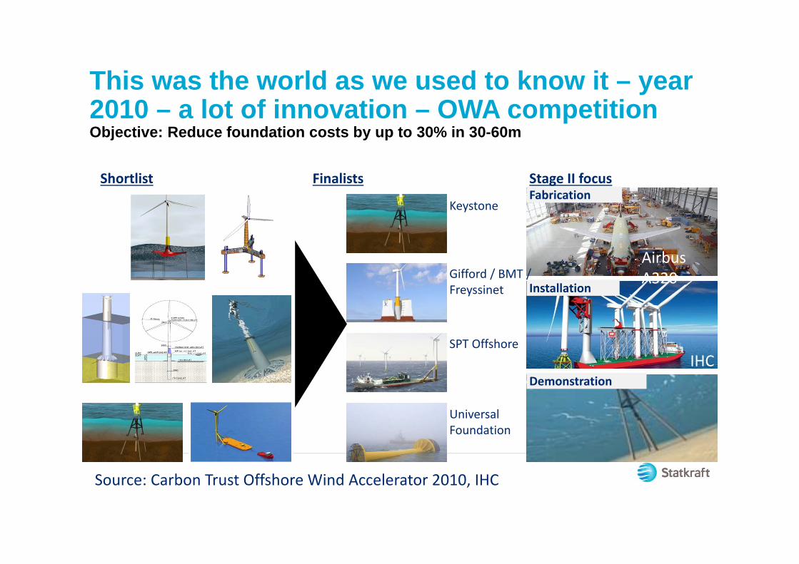
Fabrication
This was the world as we used to know it – year 2010 – a lot of innovation – OWA competitionObjective: Reduce foundation costs by up to 30% in 30-60m
Shortlist Finalists
Keystone
Gifford / BMT /Freyssinet
SPT Offshore
UniversalFoundation
Airbus A320
Source: Carbon Trust Offshore Wind Accelerator 2010, IHC
IHC
Stage II focus
Installation
Demonstration

This is more or less where we ended for bottom fixed
Source: A2Sea News - Winter 2013 and EEW SPC
20022002 20082008 20122012 20142014 20152015 20182018
Horns Rev 12.0 MW
Water depth up to 14 m
Lynn3.6 MW
Water depth up to 18 m
London Array3.6 MW
Water depth up to 25 m
Baltic II3.6 MW
Water depth up to 27 m
Gode Wind II6 MW
Water depth up to 35 m
Future MP‘s8+ MW
Water depth up to 40 m
L 34 mØ 4 m160 t
L 34 mØ 4 m160 t
L 45 mØ 4.7 m
350 t
L 45 mØ 4.7 m
350 t L 68 mØ 5.7 m
650 t
L 68 mØ 5.7 m
650 t L 73.5 mØ 6.5 m
930 t
L 73.5 mØ 6.5 m
930 tL 80 mØ 8.5 m1050 t
L 80 mØ 8.5 m1050 t L >80 m
Ø >9 m>1050 t
L >80 mØ >9 m>1050 t
EEW SPC/BladtEEW SPC/Bladt EEW SPCEEW SPCSIFSIF MT HojgaardMT Hojgaard EEW SPC/BladtEEW SPC/Bladt

0 0,1 0,2 0,3 0,4 0,5 0,6 0,7
Pow
er s
pect
ral d
ensi
ty
Frequency [Hz]
Wavespectrum5MW10 MW
By Loup/Lene
Statkraft/NTNU
Design challenge of support structure with increasing rotor diameter
6
Lower rotational speed of large turbines give lower 1P and 3P regions

Design trends on bottom fixed turbines
Large turbines (6-10 MW, 150 - 200 meter diameter)
Simple substructures – mono-columns, jackets
Possible integrated installation (foundation, tower, nacell and rotor in onepiece) but has not shown to be economical so far
INTEGRATED design – optimize tower and foundation design
7
Design phases XL - monopiles
Details in combination of wind/wave and fault loads driven by design phase:- Conceptual - FEED- Detailed
USE METOCEAN AND LOADDATA CONSISTENTLY THROUGHOUT THE DESIGN VERIFICATION PHASE
8
Figure confidential
Content From innovation to scaling and optimization
Highly integrated structures – the support structures as a dynamic unit
Metocean design basis in integrated design
IEC-64100-3 and DNV-S-J101 in deriving wind/wave/fault design loads
Analysis and statistical challenges
Conclusions
9

The bottom fixed offshore wind turbineAN INTEGRATED structure
10
The “cut”
Content From innovation to scaling and optimization
Highly integrated structures – the support structures as a dynamic unit
Metocean design basis in integrated design
IEC-64100-3 and DNV-S-J101 in deriving wind/wave/fault design loads
Analysis and statistical challenges
Conclusions
11

Design basis – metocean requirements Wave growth by wind action
Nonlinear wave-wave interaction
Dissipation due to white-capping, bottom friction and depth-induced wave breaking.
Refraction and shoaling due to depth variations
If deemed relevant, wave-current interactions
12
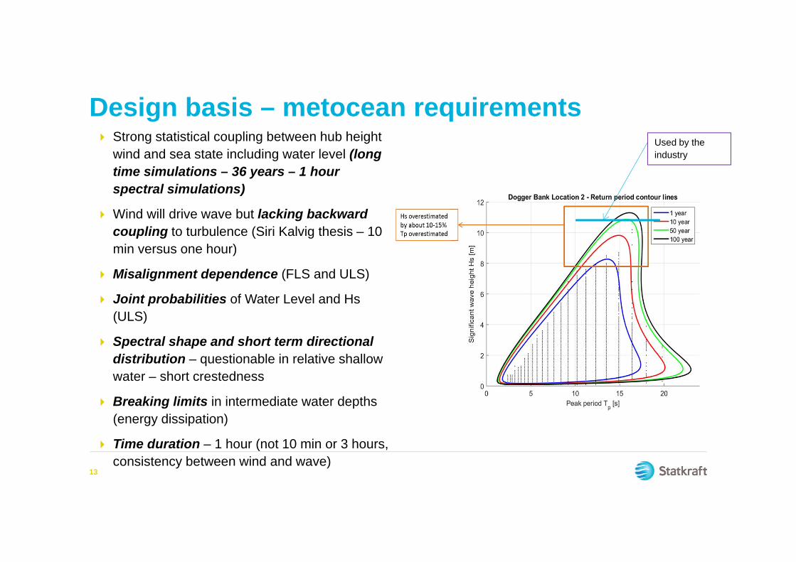
Design basis – metocean requirements Strong statistical coupling between hub height
wind and sea state including water level (long time simulations – 36 years – 1 hour spectral simulations)
Wind will drive wave but lacking backward coupling to turbulence (Siri Kalvig thesis – 10 min versus one hour)
Misalignment dependence (FLS and ULS)
Joint probabilities of Water Level and Hs (ULS)
Spectral shape and short term directional distribution – questionable in relative shallow water – short crestedness
Breaking limits in intermediate water depths (energy dissipation)
Time duration – 1 hour (not 10 min or 3 hours, consistency between wind and wave)
13
Used by the industry
Content From innovation to scaling and optimization
Highly integrated structures – the support structures as a dynamic unit
Metocean design basis in integrated design
IEC-64100-3 and DNV-S-J101 in deriving wind/wave/fault design loads
Analysis and statistical challenges
Conclusions
14

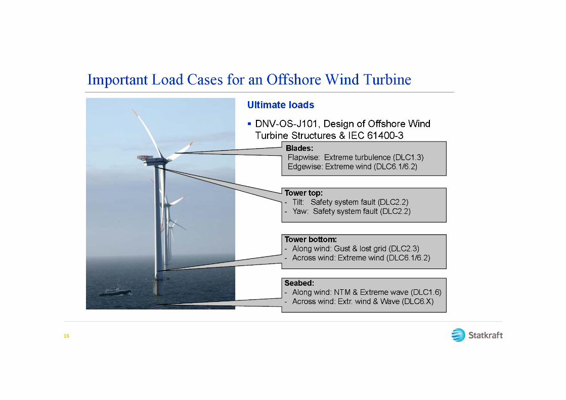
Some important considereations DNV-OS-J101
15
Combination of wind and wave loads a huge challenge for the offshore wind industry.
Why? Consequence?
16
17
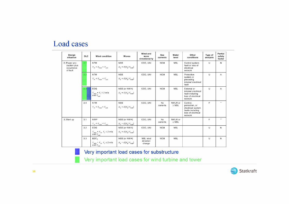
18

19
Content From innovation to scaling and optimization
Highly integrated structures – the support structures as a dynamic unit
Metocean design basis in integrated design
IEC-64100-3 and DNV-S-J101 in deriving wind/wave/fault design loads
Analysis and statistical challenges
Conclusions
20
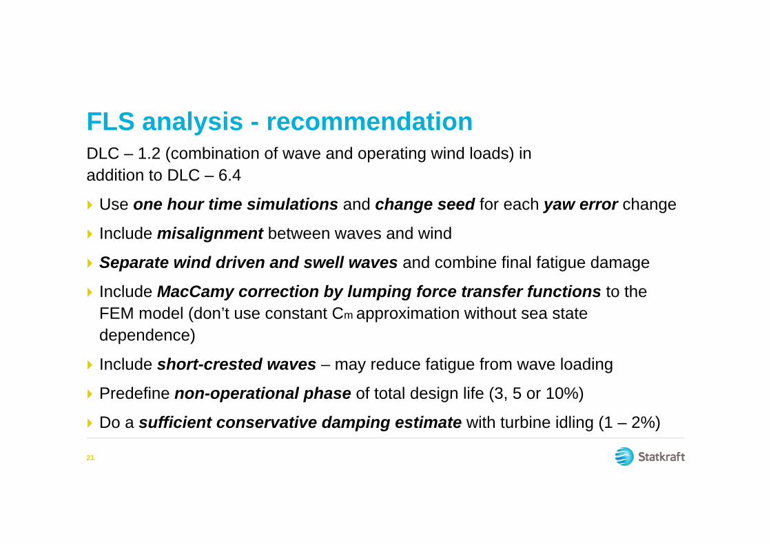
FLS analysis - recommendationDLC – 1.2 (combination of wave and operating wind loads) in addition to DLC – 6.4
Use one hour time simulations and change seed for each yaw error change
Include misalignment between waves and wind
Separate wind driven and swell waves and combine final fatigue damage
Include MacCamy correction by lumping force transfer functions to the FEM model (don’t use constant Cm approximation without sea state dependence)
Include short-crested waves – may reduce fatigue from wave loading
Predefine non-operational phase of total design life (3, 5 or 10%)
Do a sufficient conservative damping estimate with turbine idling (1 – 2%)
21
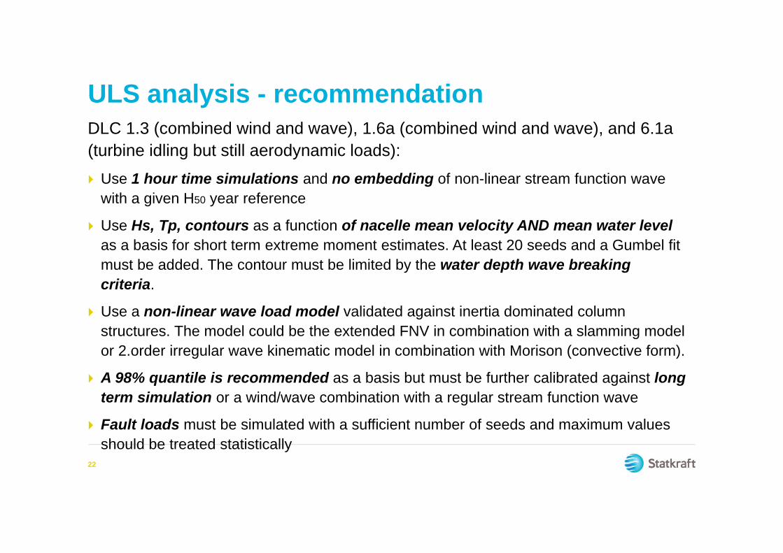
ULS analysis - recommendationDLC 1.3 (combined wind and wave), 1.6a (combined wind and wave), and 6.1a (turbine idling but still aerodynamic loads): Use 1 hour time simulations and no embedding of non-linear stream function wave
with a given H50 year reference
Use Hs, Tp, contours as a function of nacelle mean velocity AND mean water level as a basis for short term extreme moment estimates. At least 20 seeds and a Gumbel fit must be added. The contour must be limited by the water depth wave breaking criteria.
Use a non-linear wave load model validated against inertia dominated column structures. The model could be the extended FNV in combination with a slamming model or 2.order irregular wave kinematic model in combination with Morison (convective form).
A 98% quantile is recommended as a basis but must be further calibrated against long term simulation or a wind/wave combination with a regular stream function wave
Fault loads must be simulated with a sufficient number of seeds and maximum values should be treated statistically
22
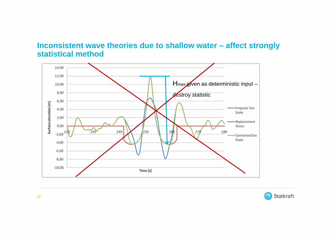
Inconsistent wave theories due to shallow water – affect strongly statistical method
23
Hmax given as deterministic input –
destroy statistic
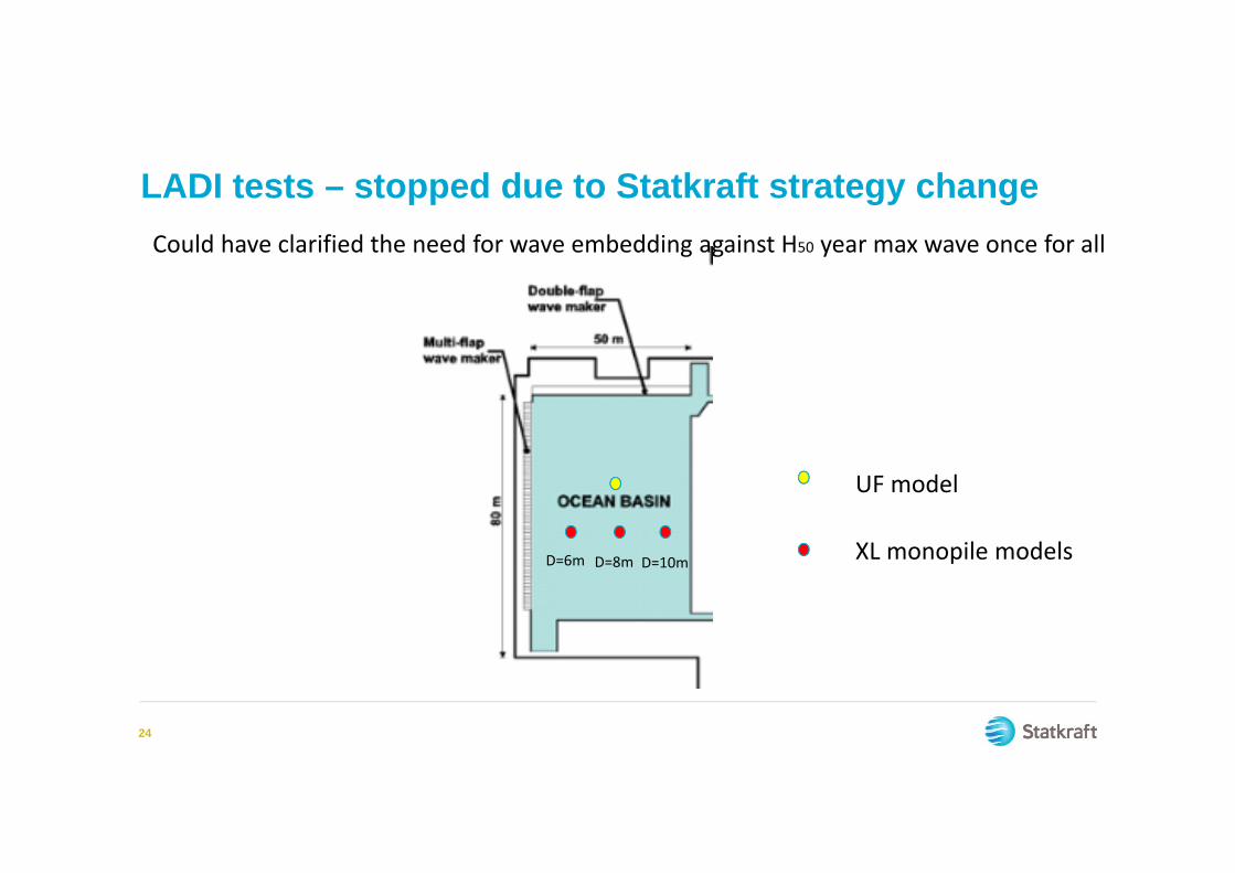
LADI tests – stopped due to Statkraft strategy change
24
UF model
XL monopile modelsD=6m D=8m D=10m
Could have clarified the need for wave embedding against H50 year max wave once for all

Conclusions It is possible to implement more optimal and consistent design methods –
closer to NORSOK – without risking the certification approval
More calibration of quantile level and verification against state of the art procedures are needed. Something for research?
As long as you can prove cost saving opportunities with the proposed method without compromising safety – DO IT!
25

www.statkraft.com
THANK YOU