RelaiXed – Assembly and Use Guide - van Eijndhoven · design is published initially in the Dutch...
17
RelaiXed – Assembly and Use Guide RelaiXed is a pre-amplifier for balanced audio connections with IR remote control. This DIY design is published initially in the Dutch 'Elektor Audio Special' DIY magazine on December 7 th , 2007. Its design and that publication are the result of a cooperation between Sander Sassen and me, Jos van Eijndhoven. This document is part of the design documentation on the website at: http://jos.vaneijndhoven.net/relaixed Document version December 7, 2007 The design of this preamp is protected under copyright, 2007. It is freely available for DIY home/hobby use. It is not allowed to use (parts of) the design for commercial use without explicit permission of the author. 1
Transcript of RelaiXed – Assembly and Use Guide - van Eijndhoven · design is published initially in the Dutch...

RelaiXed – Assembly and Use GuideRelaiXed is a pre-amplifier for balanced audio connections with IR remote control. This DIY design is published initially in the Dutch 'Elektor Audio Special' DIY magazine on December 7th, 2007. Its design and that publication are the result of a cooperation between Sander Sassen and me, Jos van Eijndhoven. This document is part of the design documentation on the website at: http://jos.vaneijndhoven.net/relaixed
Document version December 7, 2007
The design of this preamp is protected under copyright, 2007. It is freely available for DIY home/hobby use. It is not allowed to use (parts of) the design for commercial use without explicit permission of the author.
1

CharacteristicsThe design of this preamp is based on an earlier design of a passive input select and volume control for plain stereo (unbalanced) signals. That design was succesfully applied in high-end audio sets of several enthousiatic DIY builders, mostly in the Netherlands. Its simple passive design had a very clean and open sound, but the inherent large output resistance imposes limitations to its applicability. (see http://jos.vaneijndhoven.net/switchr/design.html)
The new design of this preamplifier is made for balanced stereo signals, typically connected through XLR connectors. This complements a number of power-amplifiers that recently appeared in the DIY world which prefer to operate with balanced input signals, such as the ExtremA on http://www.hardwareanalysis.com) and some commercial designs such as the Class-D modules from http://hypex.nl.This preamp maintains from the earlier passive design its 6-stage relais-based attenuator, and its IR remote control. The major modification, besides doubling for balanced operation, is of course the high-quality opamp-based output stage with its dedicated power-supply.
The preamp features infra-red remote control for audio volume and input channel selection, a 'mute' function, and -optionally- power on/off switching. Volume and channel selection is performed through small-signal relays. Two times six relays implement a 4-channel (balanced stereo) 64-step logarithmic attenuator. The combination of relays with high-quality contacts and prime quality resistors provides a top-class audio volume control, audibly better then conventional potentiometers that employ a sliding contact over a resistive layer. The chosen sealed relays will maintain their contact quality over an extremely large time span. The main ('relay') PCB carries the input selection relays, the attenuator, the active output stage, the power supply stabilization, and some digital control. With its on-board XLR connectors, this PCB is to be mounted next to the chassis real panel. An additional small 'display' PCB is intended for front-panel mounting, and accomodates the IR-reception, a 2-digit 7-segment display for visual feedback, and an optional manual control switch control. Clearly, no audio is routed to the front panel. The gold-finished PCB not only looks strikingly beautiful. The gold-finish is also really nice to solder, and some persons believe that it also has a positive effect on sound quality.
The preamp has volume levels from 00 up to and including 64. Volume levels 01 to 64 span a dynamic range of 63dB with 1.0 dB steps. A 63-dB range in power corresponds to a range of for instance from 0.1mW to 200W, depending on your power amplifier. Volume level 00 really disables all input signals giving zero output.
The design was made to provide an audio path from balanced-in to balanced-out. However, most users will also want to connect conventional 'single ended' (cinch-based) input signals. The preamp supports that, by converting these inputs also to balanced output signals. The design provides 6 selectable audio input channels. When building the design, one can choose between two configurations: either 4 single-ended input channels and 2 balanced input channels, or 3 single-ended with 3 balanced ones.
The design does not come with an IR remote control unit: the user is supposed to arrange for his/her own remote control device. The preamp has the ability to recieve different remote control protocols: the Philips RC5 and RC6 protocols as well as the Sony SIRC protocol. As also other brands sometimes adhere to these same protocols, it should be rather easy to find a compatible control device. Certainly any 'generic' IR remote control unit will be fine. Within these 3 supported protocols, there is still a lot of freedom in mapping specific buttons to functions as well as support to control multiple devices from the same unit. To support this freedom, the preamp can 'learn' the button code signals which you want to tie to the preamp functions. This is accomplished through a set-up procedure explained later in this document.
2

Comments to the schematicsThe attenuator:The attenuator creates 64 volume settings with a series of 6 stages. Each stage has one switch contact and 2 resistors, for each of the 4 independent channels. The switch contact has 2 states (relay on or off), so for each channel there are 2x2x2x2x2x2 = 64 volume settings. The resistor values are chosen such that the first stage gives 1.0 or 0 dB attenuation, the 2nd stage gives 2.0 or 0 dB attenuation, the 3rd 4.0 dB, ... , the 6th gives 32 or 0 dB attenuation. By an intelligent design of the switch schematics and resistor values, the different stages do not influence each others attenuation. If you are interested, you can check more details regarding this topic on my other web pages at http://jos.vaneijndhoven.net/switchr/switchdesign.html and http://jos.vaneijndhoven.net/switchr/switchprog.html.
The power supply rectifiers indicate schottky type rectifier diodes. This is because schottky rectifiers do not have an effect which -for 'normal' silicon p-n diodes- is called 'reverse recovery time'. As result, they generate less high-frequency switching noise. The remaining 'switching noise' is caused by parasitic output inductance of the transformer, in combination with the fast switching-off of the diodes. These HF components are filtered and dampened by the small 10nF and 47nF capacitors and 100 ohm series resistors. In this circuit this high-frequency noise is shortened to ground: I believe this is preferrable over other designs that use small capacitors over the diodes, which leads these high-frequency components into the power-supply capacitor.
For the analog supplies, a positive and negative reference voltage is made with a popular 'TL431' shunt regulator. R7P versus R12P (and R16P versus R13P) set the reference voltage to 16.5 Volt. Although not strictly required, I prefer to use 1% accuracy resistors and the TL431 'A' grade, to obtain a more accurate match between the positive and negative reference voltage. The series coupled JFETs significantly improve the suppression of power-supply hum (over having only a series resistor). The 100μF elco's also help in hum suppression, but are specially included to filter-out the noise that is generated by the voltage references. The voltage references are followed by two times two buffer-stages to provide enough output current, separate for each audio opamp supply pin. The output current is provided by the BC337 and BC327 transistors. These transistors are controlled in a stabilization loop by the opamps, to accurately maintain the output voltage with a low output impedance over a very wide frequency range.
A few key parameters that I have measured indicate the quality of this power supply stabilization, in comparison with -just as example- the output of the LM7812 regulator on this same PCB:
Measured parameters Discrete audio supply stabilization
LM7812 for digital supply
Output white noise density, in dBV/sqrt(Hz), measured at 1kHz
-170 -125
Same in nV/sqrt(Hz) 3 560
Output 100Hz hum, in dBV -152 -85
Same in µV 0.025 56
Clicking relays....The clicking of the small relays is a clear mechanical sound. If you do not want to hear that, you should not build this preamp. The design attempts to minimize clicking noise in the audio signal itself by a) the attenuator schematics itself, and b) an optimized timing by the firmware in the relay control. Unfortunately, there still seems to be a tiny parasitic capacitive coupling from the relay coils into the audio signal. Thanks to the symmetrical schematics, this signal does not appear as differential voltage in the balanced output signal. Although I cannot guarantee total silence, clicks in the output signal do not seem to be noticable.
3

Some measurements on the audio signals:
Audio signal bandwidth is DC to 700kHz. On a 100kHz(!) square wave signal, the preamp shows a smooth output signal without overshoot:
(This picture is a photo from my oscilloscope, green curve on black background, inserted here with inverted colors.)
The distortion in the audio output is not measurable by me, with my hobby equipment. The LM4562 opamp datasheet specifies a 0.00003% distortion. Below is a spectrum analyser picture of the output, that I measured with a 750Hz sine wave. This picture suggests a distortion level of -100dB, which is 0.001%. However, when I directly measure the preamp input signal, I see almost exactly the same picture, which means that the indicated distortion is part of the applied input signal and/or part of the measurement device: my Creative Audigy-2 PC soundcard.
4

Gathering the preamp componentsA separate document is provided with a component table, that lists the detailled component types, their PCB footprint, the component count to order, and -as extra service- appropriate article numbers in three electronic web shops. As one can obtain most components easily from these shops, I intend to provide help only to acquire some specific things which otherwise might be hard to obtain. Please send me an email to request for these:
a) The PCB itselfb) The two microcontrollers preprogrammed with their firmware.c) The LM4562 dual opamps in DIL8 housing.d) A set of high-quality Dale RN60-series resistors for all audio resistors in the design.
Some comment about these components:The LM4562 are remarkable new opamps, that really push the state-of-the-art for high-quality audio opamps. Their good sound is at least partially obtained through their high bandwidth: these devices have a unity-gain bandwidth of about 55 MHz. As result they reach a high effective feedback ratio through the whole audio frequency band, leading to very low distortion figures and very low phase/timing errors. They furthermore specify an impressively low voltage noise. The high bandwidth and low noise is payed for with a relatively large quiescent current, making them warm to touch. Note that their high bandwidth requires a careful circuit design and proper PCB layout to prevent unintended oscillations. So these components are not very suitable for experimentation-boards or simple drop-in replacement in other circuits. This preamp design can also accommodate pin-compatible replacement opamps that might be easier to obtain. Decent alternatives for the LM4562 are the OPA2134, OPA2604 or NE5532.
The attenuator requires quite a set of resistors, and in the high-end audio world lots of stories circulate about the sonic qualities of various types of resistors. In general I do believe that best audio quality is achieved -where possible- with well-designed simple circuits using high-quality components. However, I also feel that quality audio components are easily over-priced and applied in places where their return-on-investment is too low. With that in mind:
• I would recommend to NOT apply low-cost small (0.25W) metal-film resistors. Such resistors tend to add an unpleasant harshness to the sound.
• Many persons claim that good-old (and cheap) carbon resistors have better sound. Unfortunately these resistors typically have a 5% tolerance, which is somewhat large for this attenuator. It is not only that the stepsize becomes unaccurate, also the equality of the left and right (or + and -) channels becomes doubtful. When you want to apply 5% resistors, I would advise to buy a larger number, sort them out by measuring their resistance, and apply matched components in the circuit.
• The provided component table lists 0.5W or 1W metal film resistors with 1% accuracy. The preamp PCB was designed to fit such larger resistors: it has a hole-distance of 0.7”, about 18mm. Among the many available brands, you might check their datasheets for their specification of 'current noise', expressed in μV/V. Typically, the larger-power resistors show a better (lower) number. It is not that I think that this current noise is itself noticable as noise-level in the audio. However, I believe that a better number here indicates a better constructed resistor with better materials and internal contacts, wich positively correlates with an improved sound.
• For this preamp design, I took a small stock of the Dale 'RN60' series resistors. These are also 0.5W 1% metalfilms, but they are broadly recognised in the audio world as very good sounding resistors. Unfortunately, they are not so easy to obtain for the hobbyist, especially in their larger size and in all the different values needed for this design. In a one-to-one comparison against Vishay-Beyslag MBE 1W resistors in one of my attenuators, I have witnessed a somewhat cleaner and warmer sound from the Dales. Such differences are small, and whether they are audible depends upon your other audio components.
5

• Of course you might try to apply significantly more expensive resistors, such as 'bulk metal foil' resistors or 'tantalum' resistors, which are both told to sound extremely good. I have no personal experience with them, but will be happy to hear your results!
About resistor values:The resistor values for the attenuator itself can be adapted to match with values from the standard E12, E24, or E48 series. The values from the E48 series are also member of (available from) the E96 series. The schematics diagrams are annotated with E12 values, but -if easily available- E24-series or E48-series values give more accurate results. The rounding of 'ideal' resistor values to E12 values introduces deviations from the ideal stepsize of 1.0dB: The average (RMS) deviation in stepsize is 0.2dB, which is still fine for normal use. Whith E48-series values, the stepsize RMS deviation is reduced to 0.04dB.Below is a table listing the extended attenuator resistor values:
About resistor value coding:Most metal film resistors have their value annotated with a 5-ring color code, with a final brown ring indicating their 1% tolerance. This color coding is documented for instance on http://www.logwell.com/tech/components/1resistor_color_code.html or with a calculator on http://www.samengstrom.com/nxl/10116/5_band_resistor_color_code_page.en.html. The Dale resistors have their value annotated with a 4-digit number coding and one trailing letter, in correspondance with the color ring coding: the first 3 digits provide a base value, and the 4th digit provides a powers-of-ten multiplier. This 4th digit can be read as the number of 0's to append behind the first three digits. For example, a code of '8252F' indicates a value of '82500' ohms or 82.5 Kohms. The final 'F' indicates a 1% tolerance. Please mount these resistors in the PCB with this value code facing upwards, so that you can later inspect the proper placement in case you would encounter difficulties with the attenuator. See my example:
6
(Values in Kohms) E12 series E24 series E48 series My Dale setR2L, R21L, R2R, R21R 82 82 82.5 82.5R3L, R22L, R3R, R22R 10 10 10.0 10.0R4L, R23L, R4R, R23R 47 43 44.2 43.2R5L, R24L, R5R, R24R 2.2 2.4 2.26 2.26R6L, R25L, R6R, R25R 27 24 23.7 24.9R7L, R26L, R7R, R26R 5.6 5.1 5.11 5.11R8L, R27L, R8R, R27R 15 15 14.7 14.7R9L, R28L, R9R, R28R 15 13 13.3 13.3R10L, R29L, R10R, R29R 10 11 10.5 10.5R11L, R30L, R11R, R30R 47 47 46.4 47.5R12L, R31L, R12R, R31R 2.7 2.7 2.61 2.49R13L, R32L, R13R, R32R 100 100 95.3 95.3R16L, R18L, R16R, R18R 100 100 100 100

About the 7-segment LED displays:The design uses a pair of 7-segment displays, with a typical character height of 10mm, in a 10-pin DIL housing. They are of the 'common anode' type, so with a common connection to '+'. Unfortunately, such displays are available with different pinouts, so not any type will work in this PCB. If you intend to buy other types as listed in my component table, please compare their pin-outs in the datasheets. The component table lists types with red LEDs. Red is well readable and creates a nice 'retro' look. Of course, you might choose to buy types in a different color. For instance at Farnell, compatible blue types are: 'FORGE EUROPA FN1-0392B050JGW' (order nr 1200606), or for yellow or green LEDs search for 'HDSP-315'.
About the PCB-mountable XLR connectors:The PCB footprint is designed to fit the Neutrik female NC3FAH or NC3FAAH series, and the male NC3MAH or NC3MAAH series. These connectors have a plastic housing and gold contacts. These 'series' still provide options like having a 'latch lock' (with a release push-button) or just a 'click and pull-back', having a 4th PCB pin that provide connection to the back chassis, or having an internal connection between the back chassis and the signal-ground pin 1. The PCB footprint allows having a ground pin, but does not connect this pin: If you want to connect that to your signal ground, you can add a small piece of wire between this pin 4 (labeled with 'G' on the PCB) and pin 1 at the bottom side of the PCB. If you prefer other XLR connectors, of course you are free to do so, but you should manually wire them to the PCB. An option would be a full-metal connector like the NC3FD-LX-B (e.g. ordernr. 1390117 at farnell.com). As explained further down, I myself prefer to NOT directly connect the chassis backside to the PCB signal ground, and hence the full-metal connector or this 4'th pin provide little or no benefit. If you end up with having a connector type that has this interconnection between the chassis (in the connector screw hole) and its pin 1 and you also do not want to use this connection, you can easily remove it from the connector (in my experience). (Note that most literature will claim that making such a direct connection is a good idea.)
7

Building the attenuatorMost of the PCB assembly process hardly needs explanation. By purpose, the design relies on conventional through-hole components only which are easy to handle manually.All component identifiers are named (identified) with a number and a trailing character that corresponds to the schematic sheet. You find these component identifiers in the schematics, printed on the PCB, and listed in the component ordering table.The frontpanel-PCB and the relay-PCB were manufactured as a single piece. So before you start soldering, you should separate the frontpanel PCB from the side of the relay-PCB with a fine saw. For mounting/soldering all components on the PCBs, choose an order with the lowest profile components first. That allows you to plug in the components, turn the PCB upside-down, and solder the leads, so that all 'loose' components will lie on you desk AND touch the PCB surface, in stead of hang in the air:
For easy and neat mounting of resistors and diodes it is convenient to use a lead bending tool such as in the neighbouring picture. You will benefit from spending a few euro's on this for many years to come. Unfortunately, these tools have gone out of fashion. Here (in the Netherlands) they can still be obtained via 'display.nl', order nr. 08.90.212.
In general I am not in favour of applying IC sockets, since in principle they can only negatively affect the design quality and robustness. However, for this design I must admit that IC sockets might be good option: Plugging the audio opamps in a socket has the advantage that at a later stage you can easily update the preamp to use a newer/different type for best sound quality. Plugging the two microcontrollers in a socket has the advantage that you can later take them out easily, and mail them back to me for a firmware update. This could prove to be useful later.
PLEASE double, and triple, check the orientation of the relais, the led-displays, and IC's before soldering: It will be practically impossible to 'unsolder' DIL (dual-in-line) components out of the PCB because of its through-metallised via's. Note that the PCB layout uses square terminals to identify pin 1 and round terminals for all other pins. The SIL-resistors R5D and R6D are symmetrical components, and can be placed in either orientation.
The voltage regulators U5P and U6P should be mounted lying down on the PCB, and fixed with small M3 bolts. The PCB top-layer ground plane shows bare-metal (pure gold :-) underneath these ICs, which helps to conduct the heat away from them. There is no need for any insulation, as the back-side of these ICs is electrically connected to ground anyhow. There is also no need for heat-conducting paste between the ICs and the PCB: the dissipation is low enough that at worst these ICs will become only mildly warm.
8
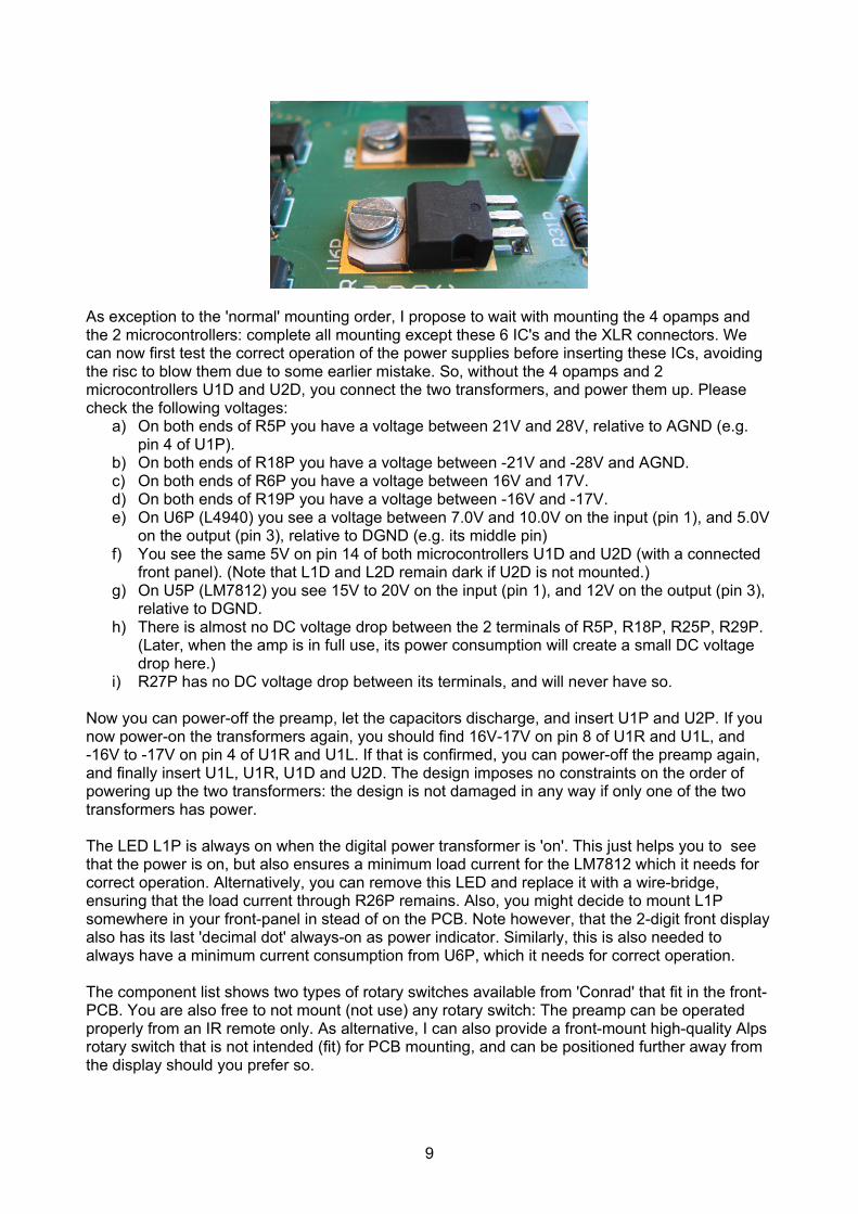
As exception to the 'normal' mounting order, I propose to wait with mounting the 4 opamps and the 2 microcontrollers: complete all mounting except these 6 IC's and the XLR connectors. We can now first test the correct operation of the power supplies before inserting these ICs, avoiding the risc to blow them due to some earlier mistake. So, without the 4 opamps and 2 microcontrollers U1D and U2D, you connect the two transformers, and power them up. Please check the following voltages:
a) On both ends of R5P you have a voltage between 21V and 28V, relative to AGND (e.g. pin 4 of U1P).
b) On both ends of R18P you have a voltage between -21V and -28V and AGND.c) On both ends of R6P you have a voltage between 16V and 17V.d) On both ends of R19P you have a voltage between -16V and -17V.e) On U6P (L4940) you see a voltage between 7.0V and 10.0V on the input (pin 1), and 5.0V
on the output (pin 3), relative to DGND (e.g. its middle pin)f) You see the same 5V on pin 14 of both microcontrollers U1D and U2D (with a connected
front panel). (Note that L1D and L2D remain dark if U2D is not mounted.)g) On U5P (LM7812) you see 15V to 20V on the input (pin 1), and 12V on the output (pin 3),
relative to DGND.h) There is almost no DC voltage drop between the 2 terminals of R5P, R18P, R25P, R29P.
(Later, when the amp is in full use, its power consumption will create a small DC voltage drop here.)
i) R27P has no DC voltage drop between its terminals, and will never have so.
Now you can power-off the preamp, let the capacitors discharge, and insert U1P and U2P. If you now power-on the transformers again, you should find 16V-17V on pin 8 of U1R and U1L, and -16V to -17V on pin 4 of U1R and U1L. If that is confirmed, you can power-off the preamp again, and finally insert U1L, U1R, U1D and U2D. The design imposes no constraints on the order of powering up the two transformers: the design is not damaged in any way if only one of the two transformers has power.
The LED L1P is always on when the digital power transformer is 'on'. This just helps you to see that the power is on, but also ensures a minimum load current for the LM7812 which it needs for correct operation. Alternatively, you can remove this LED and replace it with a wire-bridge, ensuring that the load current through R26P remains. Also, you might decide to mount L1P somewhere in your front-panel in stead of on the PCB. Note however, that the 2-digit front display also has its last 'decimal dot' always-on as power indicator. Similarly, this is also needed to always have a minimum current consumption from U6P, which it needs for correct operation.
The component list shows two types of rotary switches available from 'Conrad' that fit in the front-PCB. You are also free to not mount (not use) any rotary switch: The preamp can be operated properly from an IR remote only. As alternative, I can also provide a front-mount high-quality Alps rotary switch that is not intended (fit) for PCB mounting, and can be positioned further away from the display should you prefer so.
9

J1D and J2D are 5-pin connectors, and connect with their adjacent PIC16F819 microcontroller for precisely the set of 5 pins that are used for 'ICSP' (in-circuit serial programming). These same connectors are also used to provide the interconnect between the relay PCB and the front-PCB. To operate this latter connection, it is sufficient to connect only the middle 3 wires. However, connecting all 5 pins will not harm either. (I find it attractive to buy connectors complete with attached wires, as shown for instance in the Conrad component table. Although the component table -in agreement with the PCB layout- lists the need for 2x 5-pin connectors, you clearly need to buy only one of such a connector-with-wiring assembly.)
As tallest components, the XLR connectors will be soldered-in last.
If you want to configure the preamp with all 3 pairs of XLR inputs next to having 3 cinch inputs, the diode D4D should not be mounted. Otherwise, you can have cinch inputs also for input number 4, by connecting these to the pins marked with '+' on J4L and J4R, and do insert D4D.
10

TestingBesides testing the power supply voltages as explained in the previous chapter, you can also easily test the correct build-up of the resistor-relay attenuator chain as follows:
a) Connect a DC voltmeter across R16L, with the meter GND (or -) to its grounded terminal.b) Just for this measurement, make a temporary connection from the +5V supply to the
'inleftpos' signal, e.g. on R3L, its pin towards the front of the preamp.c) Power-up the preamp digital supply transformer. If the U1L opamp is in place, also power-
up the analog supply transformer.d) Turn the volume level up to '64'.e) The voltmeter should now indicate about 4.6V (+/- 5%).f) If you turn the volume down step-by-step, the voltage reading should go down
monotoneously, roughly according to the table below. Note that these voltages are computed from 'ideal' resistor values, not from restricted E12 or E48 series values. Due to such rounding, and due to resistor inaccuracies, your actual reading can be 5% off.
g) Perform the same type of measurement for the other three attenuator chains:i. Connect the +5V to R22L, pin towards the front, connect the voltmeter to R18Lii. Connect the +5V to R3R, pin towards the front, connect the voltmeter to R16Riii. Connect the +5V to R22R, pin towards the front, connect the voltmeter to R18R
Note the logarithmic behavior of the attenuator: for every step the voltages changes with a factor of about 1.12x, which corresponds to a 1dB change in audio sound level. If your preamp passes this test, congratulations! You have built a correctly working preamp!
11
Volume Voltage Volume Voltage Volume Voltage Volume Voltage64 4.59 48 0.73 32 0.115 16 0.018363 4.09 47 0.65 31 0.103 15 0.016362 3.65 46 0.58 30 0.092 14 0.014561 3.25 45 0.52 29 0.082 13 0.012960 2.90 44 0.46 28 0.073 12 0.011559 2.58 43 0.41 27 0.065 11 0.010358 2.30 42 0.36 26 0.058 10 0.009257 2.05 41 0.33 25 0.052 9 0.008256 1.83 40 0.29 24 0.046 8 0.007355 1.63 39 0.26 23 0.041 7 0.006554 1.45 38 0.23 22 0.036 6 0.005853 1.29 37 0.21 21 0.033 5 0.005252 1.15 36 0.18 20 0.029 4 0.004651 1.03 35 0.16 19 0.026 3 0.004150 0.92 34 0.15 18 0.023 2 0.003649 0.82 33 0.13 17 0.021 1 0.0033

Chassis routing and grounding policyHow to do proper ground wiring in audio equipment is a topic with endless discussions. I do not intend to spend my time in taking a stand in that. My personal preference is:
a) Connect a 'real earth' through the power-cord and connector to each device chassis, wherever available.
b) Use good-quality audio connectors (cinch, speaker, XLR) that are isolated from the device chassis.
c) Inside the chassis, all signal grounds (left and right, input and output) are tied together. (In this preamp on the PCB ground plane.)
d) A damping resistor of for instance 47 or 100ohm is applied in each device as the only connection between the chassis and signal ground. (Preferrably nearby the chassis back plate and the audio connectors.)
The direct earth-to-chassis connection provides required safety. The damping resistor avoids that significant stray currents can cycle between different devices through the power-ground cord and the signal ground connections. Note that 'official' XLR documents prescribe that it is best to make a hard-wired connection between the chassis and the signal-ground at the point of the chassis backplane. I agree that this is good for HF rejection, but it is -in my opinion- not a good strategy in combination with the presence of (unbalanced) cinch connectors.
The preamp design provides an option to drive a power relay to switch the 230V AC line of its own audio (2x18V) transformer and/or other equipment such as a power-amplifier. This gives the capability to use your remote control to switch on/off your complete audio set.
If the relay is applied as in the schematics below to switch-off everything except the 2x7V digital power supply transformer, the preamp power consumption is minimized in power-down mode. My (somewhat crude) measurement shows a remaining power consumption on the 230V AC line of 1.2W. This power is mostly consumed as losses in the low-cost transformer. At an electricity cost of €0.20/kWh, this permanently powered preamp will cost you about 0.6ct/day or €2.10/yr on energy. If you do not insert the relay, both power suppies are operational, and the preamp stays fully 'on', taking 10W power consumption from the 230V AC. Most of this power is dissipated in the analog power supply. Of course, the IR reception remains operational in power down mode, and allows to switch back to normal operation by remote control.
Above power measurements clearly show different transformer qualities. The above 1.2W was consumed by a low-cost 2x6V-5VA print-mount transformer of roughly €5,=. Doing the same measurement with a duo of beautiful small 7VA toriod transformers of about €15, gives a power reading of 8W in full operation and a drop to 0.1W (!) in preamp power-down mode. Although this 0.1W is clearly below my measurement accuracy, these measurements do show that it is very well possible to design always-on equipment with really negligible power consumption.
12

If you intend to switch a heavy transformer of a power amplifier, it is probably a good idea to add a 'varistor' across the primary side of the transformer. A varistor will prevent that on switching-off the transformer creates a high-voltage arc across the relais contacs. The varistor will thus help in maintaining a proper lifetime of the relais. In any case, I would select a significantly over-powered relay, to obtain a trouble-free and very long lifetime.
As alternative to using the power-relay inside the preamp chassis, you can also consider using it externally: Lead the two relay control wires from J3D to a (low-voltage type) DC-plug-connector in the back of your preamp. Build the relay inside a power-line socket strip, intend for main power distribution. Create a low-voltage wire from the relay-coil to a DC-plug, to connect to the preamp. You can now switch a whole bunch of external equipment with your remote control....
13

Remote controller compatibilityFirst thing to do, is find your own remote control hand-held that transmits IR signals in a format that is understood by the preamp. In practice there exist many different formats, some of which are shared by multiple companies/brands. Clearly, within each format, many different codes are used related with activating different functions on different devices. Your preamp understands the classic Philips RC5 and their newer RC6 format, as well as the Sony SIRC protocol. For technical information on these formats see for instance the nice website at http://www.sbprojects.com/knowledge/ir/ir.htm. All generic (multi-brand) IR remotes can send at least 2 of these 3 formats. Personally I am using a left-over 'hauppage' remote from some old PC-TV card.
If you power-up the attenuator (the display PCB), and everything works correctly, the display shows ‘P .’ for about 5 seconds, then shows ‘C1.’ for about 2 seconds, and then continues to show ‘15.’. The small dot is merely a ‘power-on’ indicator. The P indicates that the device is in a mode susceptible to programming (learning IR codes). The C1 indicates that audio input channel 1 is currently selected, and 15. indicates the current volume level.
When sending a IR signal to the device three reactions are possible:• ‘--.’ This indicates that the device cannot handle the format of the received IR signal.
You have to find yourself a different remote (or, for a multi-brand remote, experiment with a different mode). This error signal is only displayed during the 5-seconds power-up programming mode.
• ‘ 3.’ Some changed one- or two-digit numeric result means that the device performs a proper reaction on an understood button function.
• No reaction whatsoever, the displayed volume level remains. This indicates that the device doesn't know what to do with the received IR signal. Your remote might be compatible, but the volume controller has no action associated with this particular button code. This would be the expected result for a new (still unconfigured) attenuator after the 5-second programming-period has expired.
14

Configuring your preamp IR receptionWith a compatible IR-remote you can proceed with learning your preamp to react properly on your favourite buttons. You (again) power-up the device, obtaining ‘P .’ on its display, which indicates susceptibility for programming.
a. Within these 5 seconds or so after power-up, you press some button on your remote that you do NOT want to configure in the selector, and was NOT configured earlier, such as ‘menu’, ‘OK’, or ‘FastForward’. Assume -for this text- that this button is ‘OK’. The selector reacts with ‘P1.’ on its display.
b. You can freely press ‘OK’ repeatedly, thereby cycling through ‘P1.’, ‘P2.’, … ‘P9.’, ‘P1.’… If you do not press anything for about 5 seconds, the display will go back to ‘C1.’ and ‘15.’, indicating that you left configuration mode.
c. If the display shows ‘P1.’, and you press any button other than ‘OK’, that button code is stored in non-volatile memory and will be used later for ‘Volume Up’. The display reacts with ‘ 1.’ to confirm the coding of function 1. Pressing ‘OK’ again will move you to a next button to configure.
With repeating steps b. and c. (and/or a.), you can configure the following button codes:‘P1.’ Volume Up‘P2.’ Volume Down‘P3.’ Mute on/off‘P4.’ Input channel Up‘P5.’ Input channel Down‘P6.’ Input channel select numeric 1‘P7.’ Input channel select numeric 6 (maximum channel number)‘P8.’ Power-down‘P9.’ Display mode
The numeric keypad on your remote can be used to select the audio input channel. For this purpose, the signals of the first button '1' and the last button '6' are to be programmed. As exception, you could program a different number of input channels, by choosing another value then '6'. A maximum up to 7 can be used by connecting extra relays outside the provided PCB. Programming a value of '4' would restrict later channel selection from 1 to 4 only.
The 'power down' button causes an optionally connected power-relay to switch off, as well as switch-off all on-board relays, thereby silencing the audio output signal. In power-down mode the preamp does not react on volume up/down or mute commands. The power-down mode is left upon a channel-select command or reception of a subsequent 'power down' signal.
P9 is not meant to get a preamp reaction upon an extra button, but merely changes the mode of display operation. In its default mode, the preamp continuously shows the current volume level on its display, except in power-down mode where it only shows ‘ .’ If the P9 location is programmed with the same key as 'power-down', the preamp shows on its display a reaction on the last command, by showing the newly selected input channel or the newly selected volume level for about a second. After a second, the display will always return idle (black) again. Some persons prefer this normally-black display for drawing less visual attention. If you program P9 with any other button, e.g. some digit, you will get back the default behavior with a continuous volume-level display.
15

Ready to useWaiting a few seconds or pressing a recognised command code will exit the program mode and enter normal use mode. Sending a command will cause the resulting new volume or input channel to be shown on the display. Channel select up/down has cyclic wrap-around. Pressing a of digit 1 to 6 selects the corresponding audio input channel. The 'mute' command both mutes and unmutes, volume changes also unmute. The 'power down' command not only performs 'power down', but also power-up after waiting for a short delay. Power-up is also induced by input channel selection.
The preamp normally would be built with the rotary switch in the front-panel, although having this switch is just optional. Turning the rotary increases or decreases the audio volume. This type of switch has no end-point: it gives purely incremental (relative) updates. At the scale end-points (volume 64 and 00) the volume level is clipped by the microcontroller firmware. If the preamp was in audio 'mute' state, turning the volume end this mute state. The proposed type rotary switch also has a built-in push-button. Clicking this (pressing on the knob), switches to the next audio input channel. After channel '6' it cycles back to '1'. If the preamp was in 'power down' mode, the first click will only power-up the preamp. If you keep the button pressed for about 5 seconds the preamp will turn-off (go to power-down state).
The preamp display PCB stores its last used volume and channel selection in non-volatile (EPROM) memory, to remember this setting when you really switch-off its power supply. When the AC power is restored, it reads its saved settings to start-up in its previous state.
Happy listening!
Jos van EijndhovenDecember 2007
16

Appendix 1: Patch in 1st version PCBUnfortunately I discovered just too late an error in my current (first version) of the PCB, that shows 'december 2007': the male (output) XLR connectors are correctly connected in the schematics diagram, but their PCB footprint has its pins 1 and 2 swapped (signal '+' and GND). For these first PCB's I will take care of the following patches for J7L and J7R:
Top side: disconnect the left pin from the gnd plane Bottom side : disconnect the '+' and make a bare piece of gnd plane near the right pin signal from the wrong pin
When these two connectors are mounted, you should take care of new connections:
Here (left photo) I made a new GND connection at the top side by soldering a small bended wire from the XLR connector to the PCB GND-plane. However, I cannot say that this is a beautiful result. Maybe it would be nicer to make a new GND connection with a small wire along the bottom side. On the bottom side (right photo) I added the new 'signal +' connection to the proper XLR pin. Note in this photo the optional 4'th pin (center back) on this version of the connector which connects to the chassis backpanel.
17