Rehabilitation Plan for Lanxess 102 Amendment
61
_______________________________________________________________________________________ Digby Wells and Associates (South Africa) (Pty) Ltd (Subsidiary of Digby Wells & Associates (Pty) Ltd). Co. Reg. No. 2010/008577/07. Fern Isle, Section 10, 359 Pretoria Ave Randburg Private Bag X10046, Randburg, 2125, South Africa Tel: +27 11 789 9495, Fax: +27 11 789 9498, [email protected], www.digbywells.com _______________________________________________________________________________________ Directors: DJ Otto, GB Beringer, LF Koeslag, AJ Reynolds (Chairman) (British)*, J Leaver*, GE Trusler (C.E.O) *Non-Executive _______________________________________________________________________________________ Rehabilitation Plan for Lanxess 102 Amendment Project Number: LAN3111 Prepared for: Lanxess Chrome Mining (Pty) Ltd March 20155
Transcript of Rehabilitation Plan for Lanxess 102 Amendment

_______________________________________________________________________________________ Digby Wells and Associates (South Africa) (Pty) Ltd (Subsidiary of Digby Wells & Associates (Pty) Ltd). Co. Reg. No. 2010/008577/07. Fern Isle, Section 10, 359 Pretoria Ave Randburg Private Bag X10046, Randburg, 2125, South Africa Tel: +27 11 789 9495, Fax: +27 11 789 9498, [email protected], www.digbywells.com _______________________________________________________________________________________ Directors: DJ Otto, GB Beringer, LF Koeslag, AJ Reynolds (Chairman) (British)*, J Leaver*, GE Trusler (C.E.O) *Non-Executive _______________________________________________________________________________________
Rehabilitation Plan for Lanxess 102
Amendment
Project Number:
LAN3111
Prepared for:
Lanxess Chrome Mining (Pty) Ltd
March 20155

Rehabilitation Plan
LAN3111
Digby Wells Environmental i
This document has been prepared by Digby Wells Environmental.
Project Name: Rehabilitation Plan for Section 102 Amendment for Lanxess
Chrome Mine
Project Code: LAN3111
Name Responsibility Signature Date
Brett Coutts Report Compiler
March 2015
Wayne Jackson Reviewer
March 2015
This report is provided solely for the purposes set out in it and may not, in whole or in part, be used for any other purpose
without Digby Wells Environmental prior written consent.

Rehabilitation Plan
LAN3111
Digby Wells Environmental ii
EXECUTIVE SUMMARY
Digby Wells Environmental (Digby Wells) has been appointed by Lanxess to compile a
rehabilitation plan for the Lanxess Chrome Mine for the expanded underground section and
for the new proposed opencast section, in support of the Section 102 amendment
undertaken in terms of the Mineral and Petroleum Resources Development Act, 2002 (Act
No. 28 of 2002) (MPRDA). The rehabilitation plan is based on all associated surface
infrastructure that will be constructed in support of the additional mining activities proposed
for the site.
The overall objectives of this report are as follows:
■ Minimise impacts that have occurred within the area and avoid further degradation of
the environment;
■ Provide recommendations on the earthmoving required to obtain a sustainable
topography;
■ Develop a conceptual post mining sustainable topography plan;
■ Provide recommendations with respect to soil stripping, placement and soil
management;
■ Provide recommendations regarding vegetation re-establishment and re-enforcement;
■ Assist with recommendations regarding water management;
■ Provide recommendations for monitoring of rehabilitated areas and post closure
environment; and
■ Ensure that all recommendations comply with relevant local and national regulatory
requirements.
Lanxess Chrome Mine is located 7 km east of Kroondal and 11 km south-east of Rustenburg
and falls within the Rustenburg Local Municipality of the North West Province. The current
mining rights of Lanxess cover various portions of the farms Kroondal 304 JQ, Rietfontein
338 JQ and Klipfontein 300 JQ. The extent of this area is 952.5 ha. The mine is part of a
mineral deposit known as the Bushveld Igneous Complex which holds the majority of South
Africa’s chrome ore deposits. Currently the only mining that is taking place is done
underground. The ore is broken underground and brought to the surface through conveyor
belts.
The process will involve the authorisation of the proposed open pit mining operation on the
farm Rietfontein 338 JQ (owned by the mine) and the proposed underground mining
operations on portions of the farms Kroondal 304 JQ, Klipfontein 300 JQ and Brakspruit 299
JQ. Glencore Operations South Africa (Pty) (Ltd) (formally known as Xstrata) currently holds
the mining rights for some of these areas which are currently in the legal process of being
transferred to Lanxess.

Rehabilitation Plan
LAN3111
Digby Wells Environmental iii
According to the previous Environmental Management Plan undertaken in 2006, the post-
mining land use should be restored to either grazing and/or cultivation and should represent
the pre-mining land use, thus the post-mining land use considered for this rehabilitation plan
is aligned with the previous EMP.
The rehabilitation of Lanxess Chrome Mine will require significant levels of control and
monitoring during implementation if the desired objectives are to be achieved. In brief, these
objectives are:
■ Produce a free draining, and stable topography (landscape);
■ Ensure erosion free, sustainable vegetation;
■ Rehabilitation (as far as possible) of the affected areas; and
■ Minimise long term pollution potential.
The Lanxess Chrome Mining operation aims to employ concurrent rehabilitation methods
(direct replacement) of overburden materials from the current mining strip to the completed
mining strips (open voids) with the ultimate goal to return the project area as far as possible
back to the most sustainable landscape either the original landscape/topography or to a
novel topography that is free draining and matches the surrounding topography.
Based on preliminary calculations done thus far it is assumed that there should be enough
material to backfill the open pit that will be left once mining has ceased. In addition to this
there should be enough material to rehabilitate and profile the area back to the pre-mining
topography or close enough to the pre-mining topography as possible. In the event that the
area cannot be rehabilitated back to the pre-mining topography, then the area must be
rehabilitated to a state that matches the surrounding topography. Special attention must be
given when placing material back into the pit and profiling to ensure that the landscape is
free draining and that no ponding of water occurs. It is always important to ensure that there
is a reserve of topsoil material for the touch up applications, to fill small depressions that
may occur as a result of subsistence.
Conclusion
The rehabilitation of Lanxess Chrome Mine will require significant levels of control and
monitoring during implementation if the desired objectives are to be achieved. In brief, these
objectives are:
■ Produce a free draining, stable topography (landscape);
■ Ensure erosion free, sustainable vegetation;
■ Rehabilitation, as far as possible, of the affected areas; and
■ Minimise long term pollution potential.

Rehabilitation Plan
LAN3111
Digby Wells Environmental iv
In this report two types of management areas (operational and rehabilitated management
areas) have been identified which have and will be affected by mining and require
rehabilitation. Overburden and soil stockpiles have been measured and the estimates
indicate that sufficient material is available on site to create a stable and free draining
environment at closure as close to the pre-mining topography as possible.

Rehabilitation Plan
LAN3111
Digby Wells Environmental v
TABLE OF CONTENTS
Introduction ....................................................................................................................... 2 1
Terms of Reference .......................................................................................................... 2 2
Legal Setting ..................................................................................................................... 3 3
Study Area and Brief Project Description .......................................................................... 4 4
Expertise of the Specialist ................................................................................................. 5 5
Methodology and Approach .............................................................................................. 5 6
Assumptions and Limitations ............................................................................................ 6 7
Mining Activities and Management ................................................................................... 8 8
8.1 Opencast Mining ..................................................................................................... 8
8.1.1 Underground Mining ......................................................................................... 8
8.1.2 Reprocessing of tailings .................................................................................... 8
8.1.3 Mineral deposit ................................................................................................. 9
8.1.4 Processing ........................................................................................................ 9
8.2 Infrastructure Requirements .................................................................................... 9
8.2.1 Proposed Surface Infrastructure ..................................................................... 10
Baseline Environment ..................................................................................................... 11 9
9.1 Soils ...................................................................................................................... 11
9.2 Flora and Fauna .................................................................................................... 11
9.3 Surface Water ....................................................................................................... 12
9.4 Geohydrology ........................................................................................................ 13
9.4.1 Groundwater Quality ....................................................................................... 13
9.4.2 Acid Base Accounting (ABA) .......................................................................... 13
Rehabilitation Objectives and Approach ......................................................................... 15 10
10.1 Aims and Objectives .............................................................................................. 15
Landscape Re-shaping and Water Management ........................................................... 16 11
11.1 Material Balance Analysis ..................................................................................... 16
11.1.1 Bulking Factor and Profiling ............................................................................ 16

Rehabilitation Plan
LAN3111
Digby Wells Environmental vi
11.1.2 Acid Mine Drainage Water Management ........................................................ 17
11.2 Topography Design ............................................................................................... 19
11.3 Rehabilitation Management Areas (RMA’s) ........................................................... 19
11.3.1 Operational ..................................................................................................... 19
11.3.2 Post-mining .................................................................................................... 19
Soil Rehabilitation and Re-Vegetation ............................................................................ 20 12
Monitoring and Maintenance ........................................................................................... 22 13
Mine Closure and Rehabilitation Actions and Activities .................................................. 22 14
14.1.1 Stockpile Areas and the Waste Rock Dump ................................................... 23
14.1.2 Open Pit ......................................................................................................... 23
14.1.3 Infrastructure Areas ........................................................................................ 23
14.1.4 Sealing of the Shaft ........................................................................................ 24
14.1.5 Access Roads ................................................................................................ 24
14.1.6 Power line and Electrical Infrastructure ........................................................... 24
14.2 Monitoring Post Closure ........................................................................................ 24
14.2.1 Air Quality ....................................................................................................... 24
14.2.2 Water Monitoring ............................................................................................ 24
14.2.3 Social Aspect .................................................................................................. 24
Conclusion ...................................................................................................................... 34 15
Standard Land Preparation Guidelines ........................................................................... 36 1
1.1 Soil Stripping ......................................................................................................... 36
1.2 Supervision ........................................................................................................... 37
1.3 Stripping Method ................................................................................................... 37
1.4 Stockpiling ............................................................................................................. 37
1.5 Stockpile Location ................................................................................................. 38
1.5.1 Free Draining Locations .................................................................................. 38
1.6 Compaction ........................................................................................................... 39
1.7 Stockpile Management .......................................................................................... 39
1.8 Compaction and Equipment used during Soil Replacement .................................. 39
1.9 Compaction and Soil Moisture ............................................................................... 40

Rehabilitation Plan
LAN3111
Digby Wells Environmental vii
1.10 Multi-Layer Soil Profiles ......................................................................................... 40
1.11 Smoothing Equipment ........................................................................................... 40
1.12 Post-Mining Conceptual Landform Design............................................................. 40
1.13 Drainage Channel Designs .................................................................................... 41
Vegetation Establishment ............................................................................................... 41 2
2.1 Vegetation Establishment ...................................................................................... 41
2.2 Climatic Conditions ................................................................................................ 42
2.3 Vegetation Conservation ....................................................................................... 42
General Monitoring and Maintenance Guidelines ........................................................... 42 3
3.1 Final Topography .................................................................................................. 43
3.2 Depth of Topsoil Stripped and Replaced ............................................................... 43
3.3 Chemical, Physical and Biological Status of Replaced Soils .................................. 43
3.3.1 Erosion ........................................................................................................... 43
3.4 Surface Water ....................................................................................................... 44
3.4.1 Drainage systems ........................................................................................... 44
3.4.2 Water quality .................................................................................................. 44
3.4.3 Groundwater ................................................................................................... 44
3.5 Vegetation Species ............................................................................................... 44
3.6 Alien Invasive Control ............................................................................................ 44
3.6.1 Alien Species Control ..................................................................................... 44
3.6.2 Integrated Control Strategies .......................................................................... 45
3.6.3 Additional Measures ....................................................................................... 45
LIST OF TABLES
Table 9-1: A summary table of the soil forms, depths, land capability, and land potential. ... 11
Table 9-2: A summary table of the Flora and Fauna aspects related to the site. ................. 12
Table 12-1: Rehabilitation species mix for terrestrial areas ................................................. 20
Table 14-1: Rehabilitation Actions and Activities for Operational RMA’s ............................. 25
14-2: Rehabilitation, Maintenance and Monitoring Actions and Activities for Post-mining
RMA’s ................................................................................................................................. 27

Rehabilitation Plan
LAN3111
Digby Wells Environmental viii
Table 14-3: Landscape Reshaping Activates ...................................................................... 31
Table 14-4: Soil Management Activities .............................................................................. 31
Table 14-5: Vegetation Management Activities ................................................................... 33
LIST OF APPENDICES
Appendix A: General Rehabilitation Guidelines
Appendix B: Draft Alien Invasive Management Procedure

Rehabilitation Plan
LAN3111
Digby Wells Environmental 1
SECTION 1:
Introduction and
Background Information

Rehabilitation Plan
LAN3111
Digby Wells Environmental 2
Introduction 1
It is recognised that post mining landscape rehabilitation is essential to reinstate a functional
end land use which positively contributes towards the future biophysical and societal
demands of the people and the animals living in proximity to a disturbed environment.
‘Effective rehabilitation’, is defined as “rehabilitation that will be sustainable, in the long term,
under normal land management practices” according to the Chamber of Mines (2007).
Mining activity in South Africa has a legacy of poor rehabilitation post extraction however this
has changed substantially in recent years due to legislation, enforcement and environmental
responsibility by Mining houses.
Mine rehabilitation must be considered as an on-going process aimed at restoring the
physical, chemical and biological quality or potential of air, land and water regimes disturbed
by mining to a state acceptable to the regulators and to post mining land users (Whitehorse
Mining Initiative, 1994).
The rehabilitation plan contained herein is compiled for the Lanxess Chrome Mine (Pty) Ltd
(Lanxess). This report builds on the existing work for the area and addresses the overall
rehabilitation objectives set. It should be seen as a living document and will be updated
during the life of the project as additional information becomes available.
Terms of Reference 2
Digby Wells Environmental (Digby Wells) has been appointed by Lanxess to compile a
rehabilitation plan for the Lanxess Chrome Mine for the expanded underground section and
for the new proposed opencast section in support of the Section 102 amendment undertaken
in terms of the Mineral and Petroleum Resources Development Act, 2002 (Act No. 28 of
2002) (MPRDA). The rehabilitation plan is based on all associated surface infrastructure that
will be constructed in support of the additional mining activities proposed for the site.
The overall objectives of this report are as follows:
■ Minimise impacts that have occurred within the area and avoid further degradation of
the environment;
■ Provide recommendations on the earthmoving required to obtain a sustainable
topography;
■ Develop a conceptual post mining sustainable topography plan;
■ Provide recommendations with respect to soil stripping, placement and soil
management;
■ Provide recommendations regarding vegetation re-establishment and re-enforcement;
■ Assist with recommendations regarding water management;
■ Provide recommendations for monitoring of rehabilitated areas and post closure
environment; and

Rehabilitation Plan
LAN3111
Digby Wells Environmental 3
■ Ensure that all recommendations comply with relevant local and national regulatory
requirements.
Legal Setting 3
Relevant legislation governing mine rehabilitation, closure cost assessment (closure
provision), and closure planning is described in the Mineral and Petroleum Resources
Development Act (Act No. 28 of 2002) (MRPDA). The definition for environmental
management plan as stated in the MPRDA is ‘means a plan to manage and rehabilitate the
environmental impact as a result of prospecting, reconnaissance, exploration or mining
operations conducted under the authority of a reconnaissance permission, prospecting right,
reconnaissance permit, exploration right or mining permit, as the case may be.’ Specific
sections include the following:
■ Section 38 on ‘Integrated environmental management and responsibility to remedy’;
■ Section 39 on ‘Environmental management programme and environmental
management plan’;
■ Section 41 ‘Financial provision for remediation of environmental damage’; and
■ Supporting MPRDA Regulations include sections 53 – 57 and 60 – 62.
There are several guideline documents which provide recommendations on how
rehabilitation and closure should be undertaken. For the purpose of the plan the following
guideline documents will be considered:
■ Guidelines for the Rehabilitation of Mined Land. Chamber of Mine of South Africa/
Coaltech. November 2007;
■ Surface Strip Coal Mining Handbook. South African Colliery Managers Association,
Project SACMA 01/03. Compiled by R J Thompson, 2005; and
■ Best Practice Guidelines (BPGs) series developed by the Department of Water Affairs
(DWA).
In addition to the abovementioned guideline documents, further regulations must be
considered pertaining to closure and rehabilitation. These are as follows:
■ Mineral and Petroleum Resources Development Act (Act 28 of 2002): Mineral and
Petroleum Resources Development Regulations (2004);
■ International Finance Corporation (IFC) Environmental, Health and Safety (EHS)
guidelines;
■ Mineral and Petroleum Resources Development Act (Act 28 of 2002);
■ Amendment Bill of 2007;
■ Constitution of the Republic of South Africa Act, 1996 (Act 108 of 1996);
■ National Environmental Management Act (Act 107 of 1998), as amended;

Rehabilitation Plan
LAN3111
Digby Wells Environmental 4
■ National Water Act (Act 36 of 1998);
■ National Environmental Management: Waste Act 2008 (Act No. 59 of 2008), as
amended;
■ Mine Health and Safety Act (Act 29 of 1996);
■ National Environmental Management: Air Quality Act (Act 39 of 2004);
■ National Heritage Resources Act (Act 25 of 1999); and
■ Conservation Agricultural Resources Act (Act 43 of 1983).
Recently, the NEMA has undergone two amendments; these amendments have now
included provisions related to financial provision and rehabilitation contained within Sections
1 (f), 7 (a), (c) and Clause 7 Amendment of Section 24 P of the third amendment to NEMA.
These amendments now specifically stipulate that activities triggered in terms on NEMA
must have a closure and rehabilitation plan compiled, which needs to include aspects related
to financial provision and rehabilitation of mining related activities.
In addition to this Draft Regulation pertaining to the Financial Provision for Rehabilitation, the
Closure and Post Closure of Prospecting, Exploration, Mining or Production Operations
(GN.940 of 31 October 2014, in terms of NEMA) have been published for comment. These
regulations will also need to be taken into account when promulgated and they will influence
how closure costs are calculated and indicate that financial provision must be included for
rehabilitation, decommissioning and closure activities and remediation and management of
latent or residual environmental impacts. In addition to this an annual assessment must be
undertaken for the above mentioned and thus resulting in the closure and rehabilitation plans
to be updated and include updated financial provision. The review must also be undertaken
by a specialist team which must include a mining engineer, a surveyor and an environmental
assessment practitioner and must be audited by an independent auditor and submitted for
approval to the Minister responsible for mineral resources within 15 months of the effective
date of issue of the right.
For rehabilitation purposes, this regulation stipulates what information will be required for the
final rehabilitation plan. The final rehabilitation, decommissioning and closure plan will form a
component of the environmental management programme and will be subjected the same
requirements of the environmental management programme with regards to opportunities.
Study Area and Brief Project Description 4
Lanxess Chrome Mine is located 7 km east of Kroondal and 11 km south-east of Rustenburg
and falls within the Rustenburg Local Municipality of the North West Province. The current
mining rights of Lanxess cover various portions of the farms Kroondal 304 JQ, Rietfontein
338 JQ and Klipfontein 300 JQ. The extent of this area is 952.5 ha. The mine is part of a
mineral deposit known as the Bushveld Igneous Complex which holds the majority of South
Africa’s chrome ore deposits. Currently the only mining that is taking place is done

Rehabilitation Plan
LAN3111
Digby Wells Environmental 5
underground. The ore is broken underground and brought to the surface through conveyor
belts.
The process will involve the authorisation of the proposed open pit mining operation on the
farm Rietfontein 338 JQ (owned by the mine) and the proposed underground mining
operations on portions of the farms Kroondal 304 JQ, Klipfontein 300 JQ and Brakspruit 299
JQ. Glencore Operations South Africa (Pty) (Ltd) (formally known as Xstrata) currently holds
the mining rights for some of these areas which are currently in the legal process of being
transferred to Lanxess.
The registered descriptions of the land for the amended applications are;
■ Portion 95 of Kroondal 304 JQ;
■ Portion 96 of Kroondal 304 JQ;
■ Portion 97 of Kroondal 304 JQ;
■ Portion 98 of Kroondal 304 JQ;
■ Re of portion 2 of the farm Klipfontein 300 JQ;
■ Re of portion 1 and portions 1, 14, 32, 34, 10 and 11 of the farm Rietfontein 338JQ.;
■ A portion of mineral area No.2; and
■ Wonderkop area: Portion 1 of the farm Spruitfontein 341JQ and portion 17, 18 and 19
(Portions of Portion 12), the remainder of Portion 12 and the Re Portion of the farm
Brakspriut 299JQ.
The following associated surface infrastructure will be constructed in support of the
additional mining activities proposed for the site:
■ Haul roads;
■ Waste dump;
■ Open pit and underground workings;
■ Office and workshop; and
■ Carport.
Expertise of the Specialist 5
The specialist involved in the compilation of the rehabilitation plan was Brett Coutts. His
curricula vitae can be made available upon request.
Methodology and Approach 6
There were a number of tasks that were involved in the compilation of this rehabilitation plan
for the Lanxess Chrome Mine namely:
■ Project initiation;

Rehabilitation Plan
LAN3111
Digby Wells Environmental 6
■ Review of all existing information;
■ Setting objectives and planning around central themes such as;
Topography;
Material volumes;
Water;
Soil; and
Vegetation.
■ GIS mapping; and
■ Report compilation.
Assumptions and Limitations 7
The following assumptions and limitations have been made:
■ The information provided in this report is based on information gathered from site
visits undertaken to date and specialist studies that were conducted;
■ The full analytical evaluations of materials (material that will be stripped, such as
topsoil, softs and overburden is based on information provided by the client and
could change if Lanxess Chrome Mine alter the mining plan with respect to volumes
of Chrome extracted (specifically for the opencast mining operations). In the event of
this occurring the analytical evaluation of materials and the topography plan will need
to be updated to cater for this;
■ The information contained within this rehabilitation plan is based on the current Life of
Mine (LoM). If there is a significant change of either other mining areas, or
infrastructure the rehabilitation plan will need to be updated to cater for this change;
■ This report must be considered as a living document. The report will be updated as
information becomes available and monitoring and rehabilitation progresses;
■ The hydrogeological impacts associated with the post-closure environment are based
on specialist studies conducted. In the event that there is a change in the mining
method it is recommended that the hydrogeological impacts associated with the post
closure environment are remodelled as the recommendations provided for water
management are based on the current LoM;

Rehabilitation Plan
LAN3111
Digby Wells Environmental 7
SECTION 2:
Mining Activities and
Baseline Environment

Rehabilitation Plan
LAN3111
Digby Wells Environmental 8
Mining Activities and Management 8
Currently the only mining that is taking place is done underground with the ore being broken
underground and brought to the surface on conveyor belts.
Proposed future mining activities will include the expansion into the neighbouring Glencore
underground areas as well as the opening of a pit within the existing Lanxess mining right
area.
8.1 Opencast Mining
Access to the shallow resource will be made by an opencast pit cut, 1 374m in strike length
and down to a vertical depth between 50m and 70m below surface. The programme
indicates that there will be free digging up to ±14m.b.s where after opencast blasting
operations will take over mining 100m x 300m block sizes at 10m cuts (using Load Haul
Dump with excavators and dump trucks). The opencast mining sequence will start on the
eastern side of the proposed pit area and progress towards the west. The final void area will
be at the western extent of the opencast pit. Waste rock and topsoil will be stockpiled
separately to the south of the opencast area. As the opencast mining progresses, the voids
created will be backfilled with overburden from the progressive opencast mining, and then
overlain by the various soil horizons and rehabilitated. The design of the highwall has been
adapted to fit the topography and crown pillar position with an angle of 60°.
Ore production rate is estimated to be 40 000 tons per month with a LOM of 5 years for the
opencast pit.
8.1.1 Underground Mining
The underground mining method used will be the standard bord and pillar system. The pillar
dimensions and bord widths are such that a safety factor of 1.6 is maintained. Primary
extraction is carried out by using drill rigs to drill the faces and conventional explosives.
Access to the underground chrome reserves is gained by means of surface declines that are
developed from the reef outcrop. Run of Mine clearance is facilitated by a series of conveyor
belts fed by underground Load Haul Dump loaders.
It is calculated that the production rate will be 30000 to 40000 tons per month with a total
LoM of 14 years.
8.1.2 Reprocessing of tailings
Lanxess has applied in terms of Section102 to obtain the rights to the PGM’s in the orebody
they are mining. If this is granted they intend to re-mine all the tailings facilities to extract the
chrome left in the tailings. The tailings generated as a result of the re-miming of the tailings
facilities, containing the PGM’s will be sold to potential buyers. The volume of the dump has

Rehabilitation Plan
LAN3111
Digby Wells Environmental 9
been surveyed and shows a contained volume of 1,735m3 with an average content of
chromite reporting to the tailings to be between 20% and 23% Cr2O3.
8.1.3 Mineral deposit
Lanxess produce four products namely; lumpy ore, metallurgical grade chrome ore, foundry
grade chrome ore, and chemical grade chrome ore:
■ Lumpy (metallurgical) ore with typically 38% – 41% Cr2O3 and a specified size
distribution is sold to the ferrochrome industry where it is processed together with coal
in an electric furnace to form ferrochrome. Ferrochrome is the master alloy used in the
production of a wide range of corrosion and heat resistant stainless steel.
■ Metallurgical grade chrome ore with 44% chrome is sold to the local ferrochrome
industry where it is processed together with coal in an electric furnace to form
ferrochrome.
■ Foundry grade chrome ore with a Cr2O3 content of typically 46.5% and a strictly
specified grain size distribution is used for the manufacture of casting moulds in
foundries. The same material is also used in the production of refractory materials.
■ Chemical grade chrome ore with a typical Cr2O3 content of 46.0% is the raw material
for the production of sodium dichromate processed by Lanxess in their other
operations (chemical plants), which is the main constituent of all chrome chemicals.
Chrome chemicals are used for example as leather tanning agents.
8.1.4 Processing
The Lanxess Chrome Mine processing plant treats LG6 ore to produce the four chrome
products by means of Heavy Medium Separation (HMS) in the HMS Plant and Gravity
Concentration in the Gravity and Pilot Plants. The HMS plant has a capacity of 3600 tonnes
per day and the gravity plant has a capacity of 1800 tons per day. This processing plant will
remain in operation and will not be impacted by the proposed activities.
All products are sold to external clients. Chemical grade is also sold to other Lanxess
business sites for the production of chrome chemicals. A high level block flow diagram of the
processing plant is shown below.
8.2 Infrastructure Requirements
Lanxess is a well-established mine with existing infrastructure which has been operational
since 1958. As a result minimal additional infrastructure will be required for the expansion of
the activities as the plant has capacity for the proposed 80 000tpm.

Rehabilitation Plan
LAN3111
Digby Wells Environmental 10
8.2.1 Proposed Surface Infrastructure
The following associated surface infrastructure will be constructed in support of the
additional mining activities proposed for the site.
■ Haul Roads and Service Road – Approximately 3km of haul roads to accommodate
two lanes of traffic. A service road will be constructed to provide access to opencast
pit from the southern boundary of the site. These roads will be gravel or tarred;
■ Dump – An additional waste rock dump will be required alongside the opencast pit for
overburden removed during mining;
■ Stockpile – An additional topsoil stockpile will be located between the waste rock
dump and the N4 highway. This will be screened off by trees; and
■ A small workshop, office block and parking area will be built in the area of the
opencast pit.
No additional infrastructure is required for the underground areas.
Rehabilitation Plan
LAN3111
Digby Wells Environmental 11
Baseline Environment 9
9.1 Soils
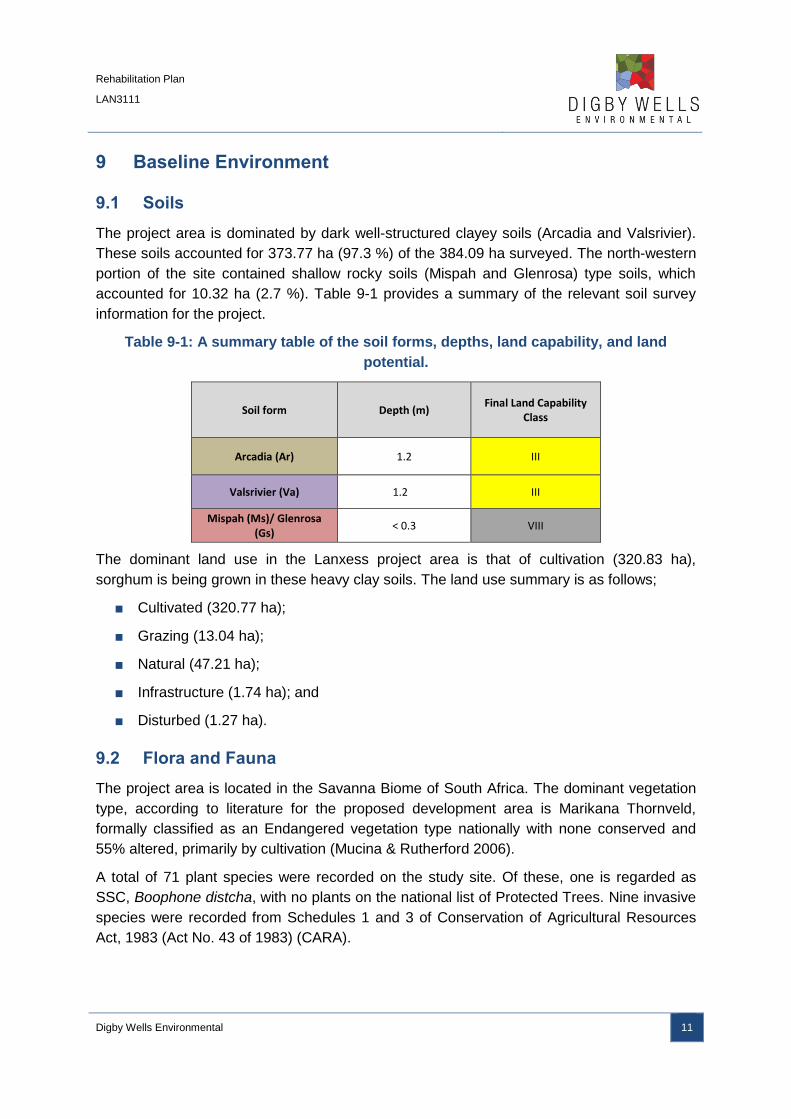
The project area is dominated by dark well-structured clayey soils (Arcadia and Valsrivier).
These soils accounted for 373.77 ha (97.3 %) of the 384.09 ha surveyed. The north-western
portion of the site contained shallow rocky soils (Mispah and Glenrosa) type soils, which
accounted for 10.32 ha (2.7 %). Table 9-1 provides a summary of the relevant soil survey
information for the project.
Table 9-1: A summary table of the soil forms, depths, land capability, and land
potential.
Soil form Depth (m) Final Land Capability
Class
Arcadia (Ar) 1.2 III
Valsrivier (Va) 1.2 III
Mispah (Ms)/ Glenrosa (Gs)
< 0.3 VIII
The dominant land use in the Lanxess project area is that of cultivation (320.83 ha),
sorghum is being grown in these heavy clay soils. The land use summary is as follows;
■ Cultivated (320.77 ha);
■ Grazing (13.04 ha);
■ Natural (47.21 ha);
■ Infrastructure (1.74 ha); and
■ Disturbed (1.27 ha).
9.2 Flora and Fauna
The project area is located in the Savanna Biome of South Africa. The dominant vegetation
type, according to literature for the proposed development area is Marikana Thornveld,
formally classified as an Endangered vegetation type nationally with none conserved and
55% altered, primarily by cultivation (Mucina & Rutherford 2006).
A total of 71 plant species were recorded on the study site. Of these, one is regarded as
SSC, Boophone distcha, with no plants on the national list of Protected Trees. Nine invasive
species were recorded from Schedules 1 and 3 of Conservation of Agricultural Resources
Act, 1983 (Act No. 43 of 1983) (CARA).

Rehabilitation Plan
LAN3111
Digby Wells Environmental 12
The findings for the faunal component of the flora and fauna assessment are presented
below.
Table 9-2: A summary table of the Flora and Fauna aspects related to the site.
Faunal group Findings
Mammals No mammal species were recorded from the site. However, previous studies confirmed that
five species of mammals have been seen in the area of interest (Digby Wells and
Associates EIA/EMP report 2008), which are the following:
■ Steenbok;
■ Black Backed Jackal;
■ Yellow Mongoose;
■ Brown Hyena; and
■ South African Hedgehog.
Reptiles and
amphibians
One reptiles and no amphibians were recorded
Birds Twenty one bird species were recorded, none of which are protected.
9.3 Surface Water
The project area is located in the Crocodile West and Marico Water Management Area
(WMA 3) within the A22H quaternary catchment. The eastern boundary of the project area
lies on the catchment divide between A22H and A21K.
The main water course in the A22H quaternary catchment is the Hex River found on the
western side of the Project area, this river joins the Elands River which is a tributary to
Crocodile River.
There are two major tributaries to the Hex River namely Sandspruit and Waterkloofspruit.
Sandspruit flows from the south of the Project area towards the north-west direction joining
the Hex River and
Waterkloofspruit is located on the western side of the Hex River towards the Hex River and it
flows towards the eastern direction to join the Hex River.
On the eastern side of the project area is the A21K quaternary catchment which consist of
three rivers/streams namely; Sterkstroom Rivers, Kleinwater, Tshukutswe and Maretlwana
River. Sterkstroom Rivers is the main river in the quaternary and it drains in the north east
direction into the Crocodile River which is a tributary to the Limpopo River.
Within the project boundary, there were no streams or any other water resource that was
identified during the site visits.

Rehabilitation Plan
LAN3111
Digby Wells Environmental 13
9.4 Geohydrology
Groundwater information is based on the previous EIA that was conducted.
9.4.1 Groundwater Quality
Regional water chemistry within the Rustenburg Layered suite indicates an average
Electrical Conductivity (EC) of 105 mS/m with a very high variance over the geological body.
Care should be taken when considering the water for human consumption due to possible
elevated nitrate levels.
9.4.2 Acid Base Accounting (ABA)
Six samples were collected for ABA analyses from borehole GC5 to determine the potential
for AMD formation. Five samples represented the overburden with the sixth sample being a
composite of the ore material to determine if there are major differences in the chemical
properties of the between the overburden and ore.
Based on the ABA test results all the samples were classified as having a Medium
Neutralising Potential. The Medium Neutralising Potential and absence of sulphur and
therefore acid generation potential indicates that no Acid Mine Drainage (AMD) will be
formed. Neutral pH, with a high Total Dissolved Solids drainage will also not occur as no first
step in the acidification occurs. Neutral Mine Drainage (NMD) is characterised by
acidification followed by an adequate buffering capacity to result in a neutral pH, but high
salinity from the release of sulphates, acidification and resultant neutralisation by carbonate
minerals.

Rehabilitation Plan
LAN3111
Digby Wells Environmental 14
CHAPTER 3:
Rehabilitation Action Plan

Rehabilitation Plan
LAN3111
Digby Wells Environmental 15
Rehabilitation Objectives and Approach 10
10.1 Aims and Objectives
According to the previous EMP undertaken in 2006, the post-mining land use should be
restored to either grazing and/or cultivation and should represent the pre-mining land use,
thus the post-mining land use considered for this rehabilitation plan is aligned with the
previous EMP.
The closure and rehabilitation objectives for the Lanxess Chrome Mine have been defined
as the following:
■ Return land that has been mined by opencast methods to a land use similar to that
which existed prior to mining, so that the management level required to utilise the
rehabilitated land is within the means of the farmer/community who uses it;
■ Ensure that as little water as possible seeps out of the various sections of the mine,
and where this is unavoidable, ensure that the water is contained or treated, if the
volume is significant and/or if it does not meet statutory water quality requirements;
■ Demolish all mine infrastructure that cannot be used by the subsequent land owners
or a third party. The areas that are demolished will be rehabilitated to at least a
grazing land capability or the prescribed pre-mining land use. Where buildings can be
used by a third party, arrangements will be made to ensure their long term
sustainable use;
■ Clean up/rehabilitate all stockpiles and loading areas to at least a grazing capability or
the prescribed pre-mining landuse;
■ Follow a process of closure that is progressive and that is integrated into the short and
long term mine plans. The process must assess the closure impacts proactively at
regular intervals throughout project life;
■ Implement progressive rehabilitation measures, beginning during the construction and
operational phases wherever possible;
■ Leave a safe and stable environment for both humans and animals;
■ To prevent any soil, surface water, and groundwater contamination by managing all
water on site;
■ Comply with local and national regulatory requirements;
■ Form active partnerships where possible with local communities to take responsibility
for the management of the land after mining; and
■ To maintain and monitor all rehabilitated areas following re-vegetation or capping, and
if monitoring shows that the objectives have been met, then an application for closure
can be made.

Rehabilitation Plan
LAN3111
Digby Wells Environmental 16
This rehabilitation plan is comprised of five major components:
■ Re-shaping of the landforms (topography plan);
■ Operational and Post-closure water management;
■ Replacement of Soils and stripping;
■ Re-vegetation of the landscape; and
■ Monitoring and Maintenance.
Landscape Re-shaping and Water Management 11
The Lanxess Chrome Mining operation aims to employ concurrent rehabilitation methods
(direct replacement) of overburden materials from the current mining strip to the completed
mining strips (open voids), with the ultimate goal to return the project area, as far as
possible, back to the most sustainable landscape. Either to the original
landscape/topography or to a suitable topography that is free draining and matches the
surrounding topography.
A material balance analysis was completed for the mining blocks. The results are discussed
below in the bulking factor and profiling section, to determine if it is possible to return the
landscape back to original ground level with the amount of material left post-mineral
extraction. This information and planning is largely driven by the need to manage water on
the site and across the impacted areas. The topographical design is directly related to the
water management.
11.1 Material Balance Analysis
Post-mining topography is one of the most important factors to be considered in the
rehabilitation and closure processes. Generally, contouring of the filled in areas aims to
achieve the approximate original contours that existed before mining (SACMA, 2005). In
order to plan or model this process, a materials balance is needed for the full mined out area
to determine the volume of material that will be removed (i.e. chrome) and thereafter how
much will be left to replace for the rehabilitation of the landscape. This section describes the
materials balance calculations for the Lanxess Mining operations, and gives the
recommended post-mining landscape topography plan.
11.1.1 Bulking Factor and Profiling
A critical factor in the calculations of material volumes, and final landform design, is the
swell/ bulking factor of the removed materials, and thereafter the replaced materials. The
physical act of excavation breaks the rocks up into various sizes, which introduces air
pockets and increases the volume of the materials. In its simplified format, calculating the
bulking factor is done by dividing the loose cubic meters (LCM) by the bank (original) cubic

Rehabilitation Plan
LAN3111
Digby Wells Environmental 17
meters (BCM) (Heit, 2011). Soils and other fine materials will result in a negative bulking
factor as this handling generally leads to compaction after placement. In reality, the final
bulking factor is influenced by many variables including the geological properties of the
material and the design of the blasting methods. Although unpublished, an industry norm for
the bulking factor of overburden is 30-40%.
Based on preliminary calculations done thus far, it is assumed that there should be enough
material to backfill the open pit that will be left once mining has ceased. In addition to this
there should be enough material to rehabilitate and profile the area back to the pre-mining
topography, or close enough to the pre-mining topography as possible. In the event that the
area cannot be rehabilitated back to the pre-mining topography, then the area must be
rehabilitated to a state that matches the surrounding topography. Special attention must be
given when placing material back into the pit and profiling, to ensure that the landscape is
free draining and that no ponding of water occurs. It is always important to ensure that there
is a reserve of topsoil material for the touch up applications, to fill small depressions that
may occur as a result of subsistence.
11.1.2 Acid Mine Drainage Water Management
It can be anticipated that mining operations will impact on the local groundwater system in
terms of quantity and quality. There is the potential for the formation of AMD. These impacts
may only become apparent after mining has ceased and the area has been rehabilitated.
If AMD is encountered, there is a very high risk that there will be significant long term
negative impact on surface water, groundwater quality, and on aquatic systems, unless the
decanted water is effectively intercepted, collected, and treated (expected that decant will
occur).
AMD can impact on aquatic environments and once created, metals are released into the
surrounding environment and they become readily available to biological organisms. In
water, for example, when fish are exposed directly to metal and H+ ions through their gills,
impaired respiration may result from chronic and acute toxicity. Fish are also exposed
indirectly to metal through ingestion of contaminated sediments and food items (Jennings et
al, 2008). The impacts from AMD on aquatic systems can have detrimental impacts to
aquatic ecosystems leaving them devoid of most living organisms. This can be further
compounded when people and other animals depend on the river system for drinking water
and food.
Based on the findings of the ABA tests the risk for AMD formation is considered low,
however in the event or risk of AMD formation increased the mitigations measures presented
below could potentially be implemented.
If the correct mitigations are not implemented, AMD water could enter the environment and
have major impacts on the local water resources. It is of crucial importance that risk
associated with potential AMD formation is determined and the appropriate mitigation
Rehabilitation Plan
LAN3111
Digby Wells Environmental 18
measure implemented to either mitigate the impact completely or reduce the impact to
acceptable levels.
If water is allowed to cover the potential acid generating portions of the mining sequence for
the foreseeable future and does not move through the area at a large flow rate, then it is
assumed that the rate of oxidation of the these layers will be lower than expected, however
the longer term impacts associated with AMD would need to be addressed. The topsoil layer
and its vegetation will minimise the movement of oxygen from the atmosphere into
rehabilitated areas.
Possible migratory measures could include the following:
■ Undertake testing to determine the potential of AMD formation (geochemical testing)
for all hard rock formations in the pit to confirm which ones will be the major source of
AMD formation;
■ Stockpile acid generating material separately from non-acid generating material;
■ Place the acid generating material (discard, slurry and potential acid generating
waste rock at the bottom of the pit and encapsulate this material with a clay layer
(limited to the lower lying areas) to minimise the movement of oxygen between the
acid generating and non-acid generating material (place acid generating material at
the bottom of the pit);
■ Rehabilitate the surface with vegetation as soon as possible to minimise the
movement of surface water into the soil (infiltration of surface water);
■ Identify groundwater and surface water monitoring locations that are related directly
downstream of the decant positions;
■ Monitoring these locations on a quarterly basis for the next 10 years to identify trends
and to identify if AMD is occurring;
■ Reducing groundwater recharge as much as possible;
■ Preventing oxygen ingression by rehabilitating opencast areas with an upper layer of
soil which is placed over a layer of weathered material or using a capping layer of
clay;
■ Disposal of all acid generating waste material below the predicted water table in the
rehabilitated pits to minimise oxidizing conditions in the material; and
■ Preventing water from ponding on rehabilitated areas and ensure a free draining
environment over rehabilitated areas;
■ If pollution control facilities are located within strategic areas (adjacent to proposed
decant points consider utilising these facilities post closure to control decant;
■ On-going biomonitoring post closure; and

Rehabilitation Plan
LAN3111
Digby Wells Environmental 19
■ Investigations into the potential of constructing a water treatment facility post closure
to treat AMD water.
11.2 Topography Design
The post-mining landscape needs to create a sustainable new topography. From the results
of the bulking factor calculations, it is possible to return the landscape to a free-flowing
environment to resemble the original landscape. The goal is to return the post-mining
topography as close to the original landscape as possible.
The post-mining landscape should emulate the surrounding topography and be free draining
as noted in the topography description. Topography Description - Average slopes for the
western project boundary range from 0.7 % to -1.0 % for majority of the area, whilst the
steeper slopes located at the western and eastern sides of the project area boundary range
from 0.3 % to -2.1%.
11.3 Rehabilitation Management Areas (RMA’s)
11.3.1 Operational
The operational infrastructure areas need to be managed with rehabilitation in mind. There
are therefore five operational RMA’s:
■ Pit area;
■ Workshop Area;
■ Stockpiles (Hards and Soft);
■ Topsoil Stockpiles; and
■ Haul roads.
During the operational life of the mine, these areas will require certain actions and these are
described in Section 14 and Table 14-1. Appendix A will also form a big role in the
management of these areas as there are practical standard guidelines for rehabilitation.
11.3.2 Post-mining
The project area will need to be managed and maintained once rehabilitation activities have
been completed. Soil replacement, soil quality, vegetation establishment, and water
management are the most important features.

Rehabilitation Plan
LAN3111
Digby Wells Environmental 20
Soil Rehabilitation and Re-Vegetation 12
The Lanxess Chrome Mine is dominated by dark well-structured clayey soils (Arcadia and
Valsrivier). The north-western portion of the site contained shallow rocky soils (Mispah and
Glenrosa) type soils, which accounts for a small portion of the site.
These soils can be stripped and stockpiled together for later use in soil replacement for
rehabilitation. The replacement of these soils is aligned with the post-mining landscape and
is critical in ensuring successful rehabilitation. Soil fertility analysis will be needed of the
stockpiled soils to determine whether fertilisation is needed for replacement and seeding.
Table 14-2 gives actions for the post-mining landscape. The information given in Appendix A
will also form a big role in the management of these areas as there are practical standard
guidelines for rehabilitation.
Re-vegetation of the backfilled and top-soiled areas is the final action step in the
rehabilitation process. The table below is a summary of the grass species recommended for
the seed mix. If possible, commercially available and indigenous nitrogen fixing plants could
be added to the seed mixture in very small quantities i.e. not more than 5% of the total seed
mixture.
Table 12-1: Rehabilitation species mix for terrestrial areas
Grass
Scientific
name
Common
name
Perenniality Grazing
Value
Plant
succession
Grazing
status
Notes
Eragrostis
chloromelas
5%
Curly leaf
(narrow)
Perennial
tufted grass
(grows for
more than five
season)
Average Sub climax/
climax
Increaser
2 grass
Cynodon
dactylon
40%
Couch
grass
Creeping
Grass
High Pioneer Increaser
2 (alien
invasive)
Provides valuable
erosion control in
less favourable
niches
Digitaria
eriantha
25%
Common
Finger
grass
(Smuts
Finger)
Perennial
tufted grass
(grows for
longer than 5
seasons)
High Climax Decreaser
Chloris
gayana
30%
Rhodes
Grass
Weak
perennial
tufted grass
(grows for 2 to
High Sub-climax Decreaser Second season
cover

Rehabilitation Plan
LAN3111
Digby Wells Environmental 21
Grass
Scientific
name
Common
name
Perenniality Grazing
Value
Plant
succession
Grazing
status
Notes
5 seasons)

Rehabilitation Plan
LAN3111
Digby Wells Environmental 22
Monitoring and Maintenance 13
The purpose of monitoring is to ensure that the objectives of rehabilitation are met. The
physical aspects of rehabilitation should be carefully monitored during the operational phase
as well as during the progress of establishment of desired final ecosystems. In general, the
following items should be monitored continuously:
■ Alignment of actual final topography to agreed planned landform;
■ Depth of topsoil placed;
■ Chemical, physical and biological status of replaced soil;
■ Erosion status;
■ Surface drainage systems (created wetland zones) and surface water quality;
■ Groundwater quality at agreed locations;
■ Vegetation basal cover;
■ Vegetation species diversity;
■ Alien vegetation control;
■ Faunal re-colonisation; and
■ Proportion of mined land that has been fully rehabilitated.
Mine Closure and Rehabilitation Actions and Activities 14
The following is a brief summary of mine closure actions that should be undertaken. In
addition, the two tables given (Table 14-1 and

Rehabilitation Plan
LAN3111
Digby Wells Environmental 23
14-2) for the consolidated actions and activities associated with the rehabilitation of the
Lanxess project area and the consequent monitoring and maintenance needed. Lastly
additional tables have been provided for the management of landscape re-shaping, general
soil management and vegetation management (refer to Table 14-3 Table 14-4, and Table
14-5).
14.1.1 Stockpile Areas and the Waste Rock Dump
The following activities will take place at closure:
■ Any residue stockpiles need to be removed and placed in the base of the final void
(excluding the final waste rock dump that will remain);
■ It is recommended that the Waste Rock dump be shaped to an 18° slope; and
■ Topsoil will be spread over all disturbed areas and re-vegetated.
14.1.2 Open Pit
The following activities will take place at closure and during concurrent rehabilitation:
■ The opencast, will start on the Eastern side of the proposed opencast area and
progress towards the west;
■ As the opencast mining progresses, the voids created will be backfilled with
overburden from the progressive opencast mining, and then overlain by the various
soil horizons and rehabilitated;
■ There will be a final void at the end of life of mine and this will be filled with
overburden material;
■ The area will be blended in with the surrounding landscape and allowed to be free
draining;
■ Once the void has been backfilled, 300mm thick topsoil or soft overburden in place
of soil will be spread on rehabilitated areas; and
■ Once placed, the “growth medium” should then be fertilised, ripped and re-
vegetated. A small topsoil stockpile should be left for remedial work.
14.1.3 Infrastructure Areas
The following activities will take place at closure:
■ All surface plant, buildings and equipment will be removed from site;
■ Foundations will be removed to a meter (1m) below surface and placed in the final
void or disposed of at a registered landfill site if required;
■ The surface areas will be levelled and vegetated; and

Rehabilitation Plan
LAN3111
Digby Wells Environmental 24
■ All haul roads will be ripped and vegetated.
14.1.4 Sealing of the Shaft
The most important aspect in sealing adit shafts is to ensure that the safety considerations
associated with such a shaft are met. For the shaft to be sealed adequately, inert building
rubble must be backfilled into the shaft, thereby partially plugging the shaft. The sealant is
reinforced by a concrete cap, dimensions of which are governed by the size and nature of
the shaft. After sealing the adit, the final area will be covered with, sub-soil and 300 mm
topsoil and vegetated. The possible formation of methane underground once the shaft has
been sealed needs to be taken into account by placing venting boreholes strategically in the
area.
14.1.5 Access Roads
Roads required for agricultural activities will be left. All others will be ripped and vegetated.
14.1.6 Power line and Electrical Infrastructure
These will be removed from site where there is not reasonable prospect they will be needed
for agricultural, housing and/or industrial activities.
14.2 Monitoring Post Closure
14.2.1 Air Quality
Air quality will continue to be monitored and the programmes used to guide rehabilitation
activities until impact are understood and acceptable to a rural area.
14.2.2 Water Monitoring
Ground and surface water monitoring points will continue to be monitored until long term
pollution trends are understood.
14.2.3 Social Aspect
Social issues will continue to be monitored in line with the social and labour plan.

Rehabilitation Plan
LAN3111
Chapter 3: Rehabilitation Plan
Digby Wells Environmental 25
Table 14-1: Rehabilitation Actions and Activities for Operational RMA’s
Management
Area Aspect Aim Actions and Discussion
Pit area
Soil
management.
Sustainable soil
stripping for later use in
rehabilitation.
Strip the soil types together and stockpile together:
■ Strip the top 30cm of topsoil and stockpile separately from the remaining soil stripped up to a depth of 1.2m.
See Section 1, Appendix A, for preparation guidelines for the mining area.
Continuous
rehabilitation
Minimise financial
provision required for
final closure and
rehabilitation and
ensure that appropriate
rehabilitation is
undertaken.
Conduct direct replacement of hards during roll-over mining where possible.
Replace material according to post-mining topographical plan.
Workshop
Area
Water
management
Clean and dirty water
separation
Ensure the dirty water drainage leads to existing pollution control dams and is not allowed to enter the environment.
Practice dust suppression to prevent material fines from entering the wetland and surrounding environment.
Soil
management Rehabilitation planning
Accurately stockpile topsoil for later use for rehabilitation of the area.
Hards and
Softs
Water
management
Clean and dirty water
separation.
Ensure water coming from the stockpiles is not polluted in any way before being released into the environment.

Rehabilitation Plan
LAN3111
Chapter 3: Rehabilitation Plan
Digby Wells Environmental 26
stockpiles
Soil
management.
Sustainable soil
stripping for later use in
rehabilitation
Strip the soil as noted above and stockpile the top 30cm separately from the remaining soil stripped.
Vegetation and
water
management
Ensure protection of
wetland and
surrounding
environment.
Vegetate the stockpiles with desired species. Do not allow alien species to establish and spread into the adjacent wetland and
into the environment.
Topsoil
stockpiles
Soil
management Rehabilitation planning
Strip the soil as noted above and stockpile the top 30cm separately from the remaining soil stripped.
Accurately demarcate the soil stockpiles and the type of soil for later use in rehabilitation activities.
Vegetation
management
Establishment of
Vegetation
Vegetate the stockpiles with desired species. Do not allow alien species to establish and spread into the adjacent wetland and
into the environment.
Ensure vegetation cover is in a good condition to prevent erosion of the soils.
Haul Roads
Soil
management.
Sustainable soil
stripping for later use in
rehabilitation
Strip the soil as noted above and stockpile the top 30cm separately from the remaining soil stripped.
Water
management
Clean and dirty water
separation
Ensure the dirty water drainage leads to the existing pollution control facilities and not into the surrounding wetlands.
Practice dust suppression to prevent excessive dust from entering the surrounding environment.

Rehabilitation Plan
LAN3111
Chapter 3: Rehabilitation Plan
Digby Wells Environmental 27
14-2: Rehabilitation, Maintenance and Monitoring Actions and Activities for Post-mining RMA’s
Management Area
Aspect Actions and Discussion
Terrestrial areas
Water management
Ensure that clean and dirty water separation is put into place to prevent dirty water from entering into areas that are not disturbed.
Soil and Erosion management
Strip the soil types together and stockpile together:
■ Strip the top 30cm of topsoil and stockpile separately from the remaining soil stripped up to a depth of 1.2m.
See Section 1, Appendix A, for preparation guidelines for the mining area.
The soils need to undergo fertility analysis prior to placement to discern whether or not fertilisation is needed to assist in rehabilitation
success.
Vegetation management
See table 12-1 for the recommended see mix for the re-vegetation efforts.
All rehabilitated areas
Monitoring
Seasonal monitoring of the soil, water and vegetation must occur during any concurrent rehabilitation.
Bi-annual monitoring may then occur once the entire project area has been reshaped and rehabilitate according to the post-mining
landscape design contained herein. Monitoring needs to continue for a minimum of three years and needs to continue if the rehabilitation
efforts are not successful.
See section 3, Appendix A, for additional guidance on monitoring.
It is advised that this rehabilitation plan is updated near the end LoM to plan for monitoring of the rehabilitation efforts.

Rehabilitation Plan
LAN3111
Chapter 3: Rehabilitation Plan
Digby Wells Environmental 28
All rehabilitated areas
Topography
The topography that is achieved during rehabilitation should be monitored and compared to the planned topography. The final profile
achieved should be acceptable in terms of the surface water drainage requirements and the end land use objectives. The survey
department should do an assessment of the reshaping carried out on the site and signoff should be obtained from the rehabilitation
specialist before the topsoil is replaced.
All rehabilitated
areas Topsoil Depth
The recovery and effective use of the usable topsoil available is very important. It is essential to undertake regular reconciliation of the
volumes stripped, stockpiled and returned to the rehabilitated areas. A topsoil balance must be used to keep track of soil resources on
the mine. In addition to this detailed records of available topsoil should be marinated and also the volume and depth of topsoil replaced.
All rehabilitated
areas
Replaced Soil Qualities
A final rehabilitation performance assessment should be done and information should be adequate for closure applications that involve:
■ Assessment of rehabilitated soil thickness and soil characteristics by means of auger observations using a detailed grid;
■ Erosion occurrences;
■ Soil acidity and salt pollution analyses (pH, electrical conductivity and sulphate) at 0-250 mm soil depth every 10 ha; and
■ Fertility analysis (exchangeable cations K, Ca, Mg and Na and phosphorus) every 16 ha (400x400 m).
Maintenance fertilization will be required to ensure that the soil fertility is adequate to support satisfactory plant growth, as this is the
main factor preventing erosion.

Rehabilitation Plan
LAN3111
Chapter 3: Rehabilitation Plan
Digby Wells Environmental 29
All rehabilitated
areas Erosion
Erosion monitoring of rehabilitated areas should be undertaken and zones with excessive erosion should be identified. Erosion can
either be quantified or the occurrence there-of simply recorded for the particular location.
All rehabilitated
areas Surface Water
The functionality of the surface water drainage systems should be assessed on an annual basis. This should preferably be done after
the first major rains of the season and then after any major storm. An assessment of these structures will ensure that the drainage on the
recreated profile matches the rehabilitation plan as well as to detect early on when any drainage structures are not functioning efficiently.
These can then be repaired or replaced before it causes significant erosion damage.
All rehabilitated
areas Groundwater
Groundwater monitoring must be undertaken to monitor potential ground water impacts. The appropriate management of groundwater
resources must be implemented in the event of impacts occurring.
All rehabilitated
areas Fauna and Flora
Basal cover refers to the proportion of ground at root level which is covered by vegetation and by the rooting portion of the cover plants. The line-transect (or the quadrat bridge) method can be used. A target of approximately 15% basal cover should be set for fully established vegetation.
Biodiversity assessments and surveys should be undertaken to establish the full range of plant species that have become established.
Biodiversity and basal cover assessments should be undertaken annually with a rotation of summer and winter assessments.

Rehabilitation Plan
LAN3111
Chapter 3: Rehabilitation Plan
Digby Wells Environmental 30
All rehabilitated
areas Settling Re-colonisation of fauna species through species assessment (Sherman and pitfall trapping).
All rehabilitated
areas
Re-vegetation failure
Areas that settle and result in ponding will need to be topped-up from the reserve stockpiles.
All rehabilitated
areas Erosion
Area in which the re-vegetation is not successful must be investigated. Once the cause has been established remedial action must be
undertaken, e.g. fertilization, ripping and replanting.

Rehabilitation Plan
LAN3111
Chapter 3: Rehabilitation Plan
Digby Wells Environmental 31
Table 14-3: Landscape Reshaping Activates
ASPECT Management
Area Aim ACTIONS
All
Management
Areas
Shaping and levelling Shaping and levelling should be undertaken as the topography plans provided.
All
Management
Areas
Clean and dirty water
separation for
rehabilitated areas
Implement clean and dirty water separation as noted above.
Erosion All Management Areas
Filling of erosion gullies that have formed.
If erosion gullies are formed they will need to be filled with stockpiled soil available and reshaped.
Table 14-4: Soil Management Activities
ASPECT Management
Area Aim ACTIONS
Compaction Reduction
All Areas Stop excess traffic over reshaped areas
Limit the amount of vehicular movement over re-profiled areas to prevent unnecessary compaction of replaced soils
Awareness of compaction
Ensure that all workers/contractors are aware of the goal of minimizing compaction throughout the rehabilitation process
Record taking Volumes of material moved should be recorded

Rehabilitation Plan
LAN3111
Chapter 3: Rehabilitation Plan
Digby Wells Environmental 32
Sol Replacement All Areas Move soils when Dry
Move/replace soil stockpiles when they are dry
Spread Overburden
Soft overburden material should be utilized over harder overburden and should be spread evenly over rehabilitated areas.
Spread cover mix
Replacement of soils with respect to depth should be aligned with the post mining capability. The following criteria can be used as a guideline:
■ Arable: soil depth will exceed 0,6 m;
■ Grazing: soil depth will be at least 0,25 m;
■ Wilderness: soil depth is less than 0,25 m but more than 0,15m; and
■ Wetland: depths as for grazing but use wetland soils which have been separately stockpiled.
Smoothing and Spreading
All Areas Smooth surface Rough level all topsoil using a dozer (not grader)
Dozer spreading All soil piles should be smoothed, by dozer, before fertilization
Fertilizing All Areas Improve growth properties
Undertake testing on soil to determine the appropriate fertilizer applications and rip through soil at least 100mm into underlying spoil material
Ripping All Areas Rip soils Rip to a depth of at least 100mm into the underlying spoil

Rehabilitation Plan
LAN3111
Chapter 3: Rehabilitation Plan
Digby Wells Environmental 33
Table 14-5: Vegetation Management Activities
ASPECT Management
Area Aim ACTIONS
Soil Dressing All Areas Sustain microbial activity
Ensure organic content sufficient within the soils which are replaced. Mulch 1 t/ha of locally mowed grass and spread. The rate should be around 1t grass/hectare, so that it gives some erosion control in addition to indigenous seed.
Improve growth properties
Once the soil properties have been established a qualified specialist should make recommendations as to fertilizer applications including timing and ratios
Spread fertilizer A commercial spreader should be used. Calibrate this using a sheet/tarpaulin. Check that the spread is uniform. It is recommended that a competent contractor is used to do the work, and that the prep work and fertilization and seeding always has close supervision
Re Vegetation All Areas Plant areas with recommended species
Vegetate rehabilitated areas with recommended seed mixture
Seed mixture for wetland areas
Seed wetland areas with recommended seed mixture.
Alien Invasive Species Management
All Areas Limit the alien invasive species colonization
Implement various control methods including selective/non-selective, contact/systemic herbicides as per
regulations. Refer to Appendix B for a Draft Procedure for Alien Invasive Management.

Rehabilitation Plan
LAN3111
Chapter 3: Rehabilitation Plan
Digby Wells Environmental 34
Conclusion 15
The rehabilitation of Lanxess Chrome Mine will require significant levels of control and
monitoring during implementation if the desired objectives are to be achieved. In brief, these
objectives are:
■ Produce a free draining, stable topography (landscape);
■ Ensure erosion free, sustainable vegetation;
■ Rehabilitation, as far as possible, of the affected areas; and
■ Minimise long term pollution potential.
In this report two types of management areas (operational and rehabilitated management
areas) have been identified which have and will be affected by mining and require
rehabilitation. Overburden and soil stockpiles have been measured and the estimates
indicate that sufficient material is available on site to create a stable and free draining
environment at closure as close to the pre-mining topography as possible.
Rehabilitation Plan
LAN3111
Chapter 3: Rehabilitation Plan
Digby Wells Environmental 35
Appendix A: General Rehabilitation Guidelines

Rehabilitation Plan
LAN3111
Appendix A: Rehabilitation Plan
Digby Wells Environmental 36
Standard Land Preparation Guidelines 1
The following points should be considered during the construction phase of the project:
■ Mine planning should minimise the area to be occupied by mine infrastructure. The
affected area should be kept as small as practically possible and should be clearly
defined and demarcated;
■ Care should be taken around sensitive landscapes e.g. areas of critical habitat to
ensure that impacts to them are minimal;
■ Construction crews should restrict their activities to planned areas. Clear instructions
and control systems should be in place and compliance to the instructions should be
policed;
■ All soil and overburden stockpiles should be located in areas where they will not have
to be removed prior to final placement. Materials should thus be placed in their final
closure location or as close as practicable to it;
■ Soils which cannot be replaced directly onto rehabilitated land should be stockpiled.
All stockpiles should be clearly and permanently demarcated and located in defined
no-go areas, re-vegetated and monitored on an annual basis;
■ Infrastructure should be designed with closure in mind. Infrastructure should either
have a clearly defined dual purpose or should be easy to demolish. This aspect of
rehabilitation should be considered if changes in the mine design are made;
■ Soil stripping is a very important process which determines rehabilitation
effectiveness. It should be done in strict compliance with the soil stripping guidelines,
which should define the soil horizons to be removed; and
■ Include rock quarries and borrow pits in the construction environmental plans.
1.1 Soil Stripping
This section explains the correct measures that should be followed during the stripping of
soil. This is a key rehabilitation activity because soils lost cannot be regenerated in the
lifetime of the mine.
Correct stripping of soils will firstly ensure that enough soils are available for rehabilitation
and secondly, that the soils are of adequate quality to support vegetation growth and thus
ensure successful rehabilitation.
The steps that should be taken during soil stripping are as follows:
■ A soil plan of the mining area is compiled and soils should be stripped making use of
this;
■ Determine stripping depths, which is dependent on the type of soil identified in the
area to be cleared;

Rehabilitation Plan
LAN3111
Appendix A: Rehabilitation Plan
Digby Wells Environmental 37
■ Ensure that mining operations do not impact on soil that is stripped or going to be
stripped;
■ Demarcate the boundaries of the different soil types;
■ Define the cut-off horizons in simple terms so that they are clear to the stripping
operator;
■ Stripping should be supervised to ensure that the various soils are not mixed;
■ Soils should only be stripped when the moisture content will minimise the compaction
risk (i.e. when they are dry);
■ The subsoil clay layers which can be found under certain hydromorphic soils need to
be stripped and stockpiled separately. This clay material can be used as a compacted
clay cap over rehabilitated pit areas that will become wetlands post-rehabilitation
(stripping of wetland soils should be avoided, however if stripping does occur the
above is recommended for stripping and stockpiling);
■ Where possible, soils should be stripped and replaced in one action i.e. soils should
only be handled once instead of moving it around two or more times.
■ Truck and shovel should preferably be used as a means of moving soil, instead of
bowlscrapers.
1.2 Supervision
A very important aspect is the supervision and monitoring during the stripping process.
Close supervision will ensure that soils are being stripped from the correct areas and to the
correct depths, and placed on the correct stockpiles with a minimum of compaction.
Monitoring requires an assessment of the depth of the soil, the degree of mixing of soil
materials and the volumes of soils that are being replaced directly or being placed on
stockpiles.
Contracts for the stripping of soils should not only be awarded on the volumes being stripped
but also on the capability to strip and place soil accurately.
1.3 Stripping Method
Soils should be stripped and replaced using the truck and shovel method as far as possible.
This method will limit the compaction of soils. If bowl scrapers are used then the soils must
be dry during stripping to minimise compaction.
1.4 Stockpiling
This section explains the correct measures to be followed during the stockpiling of soil.
Stockpiling should be minimised as far as possible since it increases compaction and
decreases the viability of the seed bank. Stripped soil should not be stockpiled but placed
directly wherever possible.

Rehabilitation Plan
LAN3111
Appendix A: Rehabilitation Plan
Digby Wells Environmental 38
The steps that should be taken during soil stockpiling are as follows:
■ Mark stockpile locations accurately on a plan to ensure that re-handling is minimised
(i.e. soils will not have to be moved a second or third time);
■ Ensure that the location is free draining to minimise erosion loss and waterlogging;
■ Minimise compaction during stockpile formation. The soils should be kept loose by,
preferably, tipping at the edge of the stockpile not driving over the stockpile (avoid
end-tipping as this causes compaction);
■ Re-vegetate with a native seed mixture (stockpiles that will remain standing for
several years); and
■ Ensure that the stockpiled soil is only used for the intended purposes.
1.5 Stockpile Location
Appropriate mitigation measures for the management of these stockpiles needs to be
implemented to ensure that wetlands and drainage paths are not affected and that the loss
of topsoil is mitigated against.
Progressive monitoring of the stripping, stockpiling, shaping of spoil surfaces and replacing
of topsoil will ensure successful post-mining land and soil reclamation. Assessing post-
mining soil characteristics and associated land capability and land uses is necessary, but
there is insufficient opportunity to correct failures during the rehabilitation process. A detailed
mine rehabilitation plan is thus required to ensure sound rehabilitation practices are adhered
to.
The detailed stripping plan should include the following information:
■ Location of soil types than can be stripped and stockpiled together;
■ Stripping depths of different soil types; and
■ The location, dimensions and volume of planned stockpiles for different soil types.
1.5.1 Free Draining Locations
Soils should normally be replaced in the landscape positions they were stripped from. Well
drained soil should therefore be replaced in high landscape positions while the wet soil is
replaced in lower lying landscape positions.
The locations of the soil stockpiles should be on a topographical crest to ensure free
drainage in all directions. If this is not possible then an alternative is a side-slope location
with suitable cut-off berms constructed upslope.
Stockpiles that are placed in drainage lines result in soils becoming water logged and a loss
of desirable physical and chemical characteristics. Such situations also result in a loss of
soils due to erosion. If stockpiles need to be placed here, hydromorphic soils should be
stockpiled in the wetter sections.

Rehabilitation Plan
LAN3111
Appendix A: Rehabilitation Plan
Digby Wells Environmental 39
1.6 Compaction
Soils should be stockpiled loosely. Achieving this will depend on the equipment being used
during the stripping and stockpiling process.
Soils should be dumped in a single lift if truck and shovel methods are used. If the dumps
are too low, then the height could be increased by using a dozer blade or back actor bucket
to raise the materials.
The use of heavy machinery should be avoided as it results in the compaction of soils and
destruction of the soil structure. It is not recommended that a bowl scraper or grader be used
to level and shape the stockpiles. If heavy machinery must be used, then compaction can be
reduced by stripping and dumping as thick a cut as possible. Deposition of soils in a single
track line may also reduce the compaction of the dumped or replaced soil.
1.7 Stockpile Management
Established stockpiles should be managed to ensure that soil losses are minimised and that
additional damage to the physical, chemical or biotic content is minimised. Stockpile soil
health, volume and biotic integrity can potentially be harmed by factors including erosion,
‘borrowing’ for other purposes, contamination and water logging.
Stockpiles should be re-vegetated to avoid soil loss due to erosion and weed colonisation if
stockpiles remain in the same location for more than one growing season and have not re-
vegetated naturally. The looseness of the soil in stockpiles should be preserved (assuming
stripping and construction of the stockpiles are done correctly) by fertilising and seeding by
hand, hydroseeding or seeding aerially to minimise the introduction of compaction. If
stockpiles are already compacted, standard agricultural equipment can be used to establish
grass cover. Weed infestation should also be controlled on the stockpiles by approved
methods and herbicides.
It is very important that soils are only used for the intended purposes. The dumping of waste
materials next to or on stockpiles, contamination by fly-rock from blasting and the pumping
out of contaminated water from pit areas are hazards to stockpiles. Employees must be
made aware of these hazards and a detailed management and monitoring programme
should be put in place.
1.8 Compaction and Equipment used during Soil Replacement
Compaction limits the effectiveness of replaced soils. The equipment used during the
replacement of the soils has a major impact on the compaction levels. Ideally heavy
machinery should not be used to spread and level soils during replacement. The truck and
shovel method should be used since it causes less compaction than, for example, a bowl
scraper.
When using trucks to deposit soils, the full thickness of the soil required can be placed in
one lift. This does, however, require careful management to ensure that the correct volumes

Rehabilitation Plan
LAN3111
Appendix A: Rehabilitation Plan
Digby Wells Environmental 40
of soil are replaced. The soil piles deposited by the trucks will have to be smoothed before
re-vegetating the area.
1.9 Compaction and Soil Moisture
The soil moisture content is a determining factor in the degree to which the soils are subject
to compaction. Each soil type has a moisture content at which the compactability is
maximised. The aim during the replacement (and removal) of soils should be to avoid the
moisture content of maximum compaction when moving soils. The best time for stripping and
replacement of soils is thus when soil moisture content is lowest which will be during the dry
season.
1.10 Multi-Layer Soil Profiles
Replacing soils in the same sequence as they occur in nature (and have been removed)
would result in considerable benefits in the re-establishment of the natural soil fertility
recycling processes since this will result in the organic-enriched, chemically fertile, soil zone
being located in the zone of maximum plant root exploitation.
Multi-layer replacement of soils is not, however, ideal from a compaction point of view
because each layer needs to be deposited and levelled before the next is replaced.
Compaction of the re-created profile can be reduced, provided the correct equipment is
used. Soils should also be dry when it is replaced in layers. In any event, ripping through all
layers of the re-created multi-layer profile will be essential.
1.11 Smoothing Equipment
The soils that are deposited with trucks need to be smoothed before re-vegetation can take
place. A dozer (rather than a grader) should preferably be used to smooth the soils since it
exerts a lower bearing pressure and thus compacts less than wheeled systems.
If the top- and sub-soils have been mixed during the stripping process then the seed-bank
has been diluted excessively and the creation of a seed-bed for planting purposes will be
required.
1.12 Post-Mining Conceptual Landform Design
The conceptual framework should be set during the permitting phase of the project and this
should thus be the end target for the mine planners, managers and other parties involved.
The final topography will be a function of the original topography, the mining method and the
reshaping strategy.
The landform design should take the following into consideration during the planning phase:
■ Volumes of product removed from the pit;
■ Expected bulking factors for the remaining materials;

Rehabilitation Plan
LAN3111
Appendix A: Rehabilitation Plan
Digby Wells Environmental 41
■ The requirement to create a final surface with a satisfactory surface water drainage
system; and
■ Structures used to keep water out of the mined area during the operational phase
should be effective post-closure as well.
1.13 Drainage Channel Designs
The construction of erosion control channels on the rehabilitated areas should be avoided as
far as possible. This can be done if reshaping and soil replacement are done during the dry
months, the slopes are short and stabilising vegetation cover establishes in the first rains. In
areas where surface water drainage systems are unavoidable, care must be taken that these
structures do not make erosion worse.
The consolidation of mine spoils (waste rock and TMF material) takes many years to
complete and once mining stops the water table re-establishes and the wetting-up of the
overburden materials may result in further settlement. This can be countered by constructing
slopes in the contour banks that are significantly steeper than their equivalents on unmined
land and by making sure that the batters are higher. The steeper slopes might result in
scouring within the channel but the risk of contour banks or drains breaking will be greatly
reduced. All drainage channels, if needed, should be designed by a “competent person”
(usually an engineer), who has experience in designing such structures on rehabilitated
ground.
Vegetation Establishment 2
2.1 Vegetation Establishment
This section explains the general principles to be adopted during vegetation establishment
and application of fertilisers for rehabilitated areas.
The main aim when re-vegetating the pits and infrastructure footprints is to restore the areas
back to the pre-mining environment so that they are self-sustaining with a natural nutrient
cycle in place and with ecological succession initiated.
Although the rehabilitated land may have variable land capability, including arable land
capability for some areas (limited), the main aim of this re-vegetation process is to establish
a stable, sustainable vegetative cover.
The objectives for the re-vegetation of reshaped and top-soiled land are to:
■ Prevent erosion;
■ Re-establish eco-system processes to ensure that a sustainable land use can be
established without requiring long-term fertilizer additions; and
■ Restore the biodiversity of the area as far as possible.
Rehabilitation Plan
LAN3111
Appendix A: Rehabilitation Plan
Digby Wells Environmental 42
2.2 Climatic Conditions
Planting will be most successful when it is done after the first rains and into freshly prepared
fine-tilled seedbeds (provided the soil material is not prone to crusting). Water retention in
the seed zone will stimulate germination and can be supported by the application of light
vegetation mulches.
2.3 Vegetation Conservation
If rare and protected flora species are found on the mining area during construction or
operational activities, they should be conserved by removing and relocating them to another
section of the project area which is suitable. The rare/protected plants can be kept in a
nursery; the plants can then be replanted during rehabilitation of the disturbed areas.
Control and management of alien vegetation will contribute to the conservation of the natural
vegetation. The alien species should, therefore, be removed from site and control measures
must be implemented to ensure spreading of these species does not occur to other parts of
the project area or the surrounding lands. Refer to Appendix B for a Draft Procedure for
control of Alien Invasive Plants.
General Monitoring and Maintenance Guidelines 3
The purpose of monitoring is to ensure that the objectives of rehabilitation are met and that
the rehabilitation process is followed. The physical aspects of rehabilitation should be
carefully monitored during the operational phase as well as during the progress of
establishment of desired final ecosystems.
The following items should be monitored continuously:
■ Alignment of actual final topography to agreed planned landform;
■ Depth of topsoil stripped and placed;
■ Chemical, physical and biological status of replaced soil;
■ Erosion status;
■ Surface drainage systems and surface water quality;
■ Groundwater quality at agreed locations;
■ Vegetation basal cover;
■ Vegetation species diversity;
■ Faunal re-colonisation; and
■ Proportion of mined land that has been fully rehabilitated.

Rehabilitation Plan
LAN3111
Appendix A: Rehabilitation Plan
Digby Wells Environmental 43
3.1 Final Topography
The topography that is achieved during rehabilitation should be monitored and compared to
the planned topography. The rate of development of the pits will determine the intervals
between these assessments. The final profile achieved should be acceptable in terms of the
surface water drainage requirements and the end land use objectives. The survey
department should do an assessment of the reshaping carried out on the site and signoff
should be obtained from the rehabilitation specialist before the topsoil is replaced. Particular
attention in terms of final topography and achieving the end goals set out would be to
monitor the progression of rehabilitation of the Waste Rock Dump. In addition to monitoring
vegetation establishment of the Waste Rock Dump is to monitor the topsoil stockpiles on an
on-going basis to ensure that these stockpiles are adequate to be used for rehabilitation in
terms of amount of topsoil and the conditions of the stockpiles to be used.
3.2 Depth of Topsoil Stripped and Replaced
The recovery and effective use of the usable topsoil available is very important. It is also
important to undertake regular reconciliation of the volumes stripped, stockpiled and
returned to the rehabilitated areas. A topsoil balance can be used to keep track of soil
resources on the mine.
A final post-mining rehabilitation performance assessment should be done and information
should be adequate for closure applications that involve:
■ Assessment of rehabilitated soil thickness and soil characteristics by means of auger
observations using a detailed grid;
■ A post-mining land capability map based on soil thickness and characteristics;
■ A proposed post-mining land use map;
■ Erosion occurrences;
■ Fertility analysis and soil analysis;
■ Representative bulk density analysis.
3.3 Chemical, Physical and Biological Status of Replaced Soils
3.3.1 Erosion
Continuous erosion monitoring of rehabilitated areas should be undertaken and zones with
excessive erosion should be identified. Erosion can either be quantified or the occurrence
there-of simply recorded for the particular location.

Rehabilitation Plan
LAN3111
Appendix A: Rehabilitation Plan
Digby Wells Environmental 44
3.4 Surface Water
3.4.1 Drainage systems
The functionality of the surface water drainage systems should be assessed on an annual
basis. This should preferably be done after the first major rains of the season and then after
any major storm. An assessment of these structures will ensure that the drainage on the
recreated profile matches the rehabilitation plan as well as to detect early on when any
drainage structures are not functioning efficiently. These structures can then be repaired or
replaced before they causes significant erosion damage.
3.4.2 Water quality
The quality of all water leaving the property should be monitored on a regular basis to
ensure compliance of the various constituents with the standards approved by the
government. Samples should be analysed for particulate and soluble contaminants as well
as biological.
Additional monitoring should include aquatic biomonitoring (invertebrates, habitat, water
quality and fish) on a bi-annual basis (high and low flow) to determine the ecological
functioning and health of the rivers and streams, in and around the rehabilitated areas. The
ecological functioning of the wetlands should similarly be assessed on an annual basis.
3.4.3 Groundwater
The groundwater levels and quality should be measured and monitored in a similar way to
the surface water to determine the impact of the mining activities on the groundwater
resources. A hydrogeologist, together with the relevant authorities, should determine the
locations of the monitoring boreholes. The monitoring frequency will be determined by the
regulator.
3.5 Vegetation Species
Biodiversity assessments and surveys should be undertaken by external experts to establish
the full range of plants that have become established. Summer and winter samplings should
be done during these assessments.
3.6 Alien Invasive Control
3.6.1 Alien Species Control
Invasive alien plant species are difficult to control. Methods should be used that are
appropriate for the species concerned, as well as to the ecosystem in which they occur.
When controlling weeds and invaders, damage to the environment must be limited to a
minimum.

Rehabilitation Plan
LAN3111
Appendix A: Rehabilitation Plan
Digby Wells Environmental 45
There are four basic methods by which encroachers or weeds are controlled:
■ Physical (mechanical):
Uprooting (hand pulling);
Cutting back;
Chopping, slashing and felling; and
Ring-barking (girdling).
■ Chemical:
Foliar application;
Stem notching and application;
Stump treatment; and
Soil treatment.
■ Biological treatment which involves the use of host-specific natural enemies of weeds
or invaders from the plant's country of origin, to either kill or remove the invasive
potential of these plants; and
■ Use of chemical treatment must be undertaken by a qualified or trained individual and
the chemicals used must be approved by authorities.
3.6.2 Integrated Control Strategies
The satisfactory control of weeds and other invasive species is usually only achieved when
several complementary methods, including biological control, improved land management
practices, herbicides and mechanical methods, are carefully integrated. Such a strategy is
termed an Integrated Control Strategy (ICS).
Follow-up control of alien plant seedlings, saplings and coppice regrowth is essential to
maintain the progress made with initial control work, and to prevent suppression of planted
or colonizing grasses. Before starting new control operations on new infestations, all
required follow-up control and rehabilitation work must be completed in areas that are
originally prioritized for clearing and rehabilitation.
3.6.3 Additional Measures
The following additional measures are recommended in order to prevent the future
introduction or spread of alien species, and to ensure the rehabilitation of transformed areas:
■ There must be no planting of alien plants anywhere within the mining area;
■ Annual surveys, aimed at updating the alien plant list and establishing and updating
the invasive status of each of the alien species, should be carried;

Rehabilitation Plan
LAN3111
Appendix A: Rehabilitation Plan
Digby Wells Environmental 46
■ The transportation of soils or other substrates infested with alien species should be
strictly controlled;
Benefits to local communities as a result of the alien plant control programme should be
maximised by not only ensuring that local labour is employed, but by also ensuring that
cleared alien trees are treated as a valuable wood resource that can be utilised.

Rehabilitation Plan
LAN3111
Appendix B: Rehabilitation Plan
Digby Wells Environmental 47
Appendix B: Draft Alien Invasive Management
Procedure

Rehabilitation Plan
LAN3111
Appendix B: Rehabilitation Plan
Digby Wells Environmental 48
1. Purpose _________________________________________________________________________ The purpose of this procedure is to ensure the effective control and eradication of Alien Invasive Plants (AIPs). AIPs are plants that have been introduced either intentionally or unintentionally, into an area or ecosystem in which they do not naturally occur. 2. Scope _________________________________________________________________________ The application of this procedure is limited to AIPs. The procedure provides a generic control for the control and eradication of AIPs. In addition to the general principles outlined in this procedure Lanxess must compile and implement a declared invader control and management plan according to Alien and Invasive Species Lists, 2014 (GN R599 in GG 37886 of 1 August 2014) of the NEMBA (Act 10 of 2004). 3. Prerequisites _________________________________________________________________________
■ Alien Invasive field survey with the key invasives identified and appropriate control
procedures confirmed for each AIP
■ Risk assessment for using hand axes and chainsaws;
■ Appropriate PPE is utilised; and
■ Ensure people are correctly trained in the machinery used.
4. Procedure
Pre task Activities
Undertake a desktop demarcation exercise, in order to demarcate the site into workable
units or areas to be cleared of AIPs. Once demarcated, these areas are to be ranked
according to priority, taking factors such as amount of vegetation occurring in the area, type
of vegetation or AIPs, the location on site, and proximity to sensitive environmental features.
If required, these areas can be further sub-divided into plots in order to allow for a systematic
approach when undertaking clearing activities.
Clearing of AIPs is to be approached systematically according to highest priority areas first,
then progressing to lower priority areas. All AIPs within demarcated areas are to be
identified prior to clearing activities commencing, in order to allow for the availability of
herbicides to be used, as well as to allow for the correct allocation of mechanical equipment
to be used and to ensure that only AIPs are removed and no other natural vegetation that
may occur within the demarcated area is affected by the removal of AIPs.
Clearing Activities

Rehabilitation Plan
LAN3111
Appendix B: Rehabilitation Plan
Digby Wells Environmental 49
The following task should be undertaken during the clearing of vegetation:
1 Clearing activities must be supervised at all times.
2 Invasive Alien Plants can be controlled using one or a combination of three methods:
Physical/Mechanical methods - felling, physical removal of plants, often in
conjunction with burning;
Chemical methods - using environmentally safe herbicides and
Biological control - using species-specific insects and diseases from the alien
plant's country of origin.
3 Often, an integrated approached is preferred, whereby a combination of the above
methods is used in combination with follow up clearing and rehabilitation
4 Mechanical and chemical control are short-term activities, whereas rigorous and
disciplined follow-up and rehabilitation are necessary in the medium term, biological
control can provide effective control in the short and medium term in some cases, and it
is often the only really sustainable solution in the longer term
5 Mechanical control options include the physical felling or uprooting of plants and their
removal from the site. The equipment used in mechanical / physical control ranges from
hand-held instruments (hand pruners, hand saws, loppers and axes) to power-driven
tools such as handsaws, chainsaws, or a string trimmer outfitted with a circular saw
blade, and even to bulldozers in some cases. Mechanical control is labour-intensive
and thus expensive to use in extensive and dense infestations, or in remote or rugged
areas.
6 Mechanical/physical control methods include:
Hand pulling;
Stem cutting of small trees (using hand pruners, hand saws, loppers and axes);
Stem cutting of large trees (using mechanical / power driven tools and devices
such as handsaws, chainsaws, or a string trimmer outfitted with a circular saw
blade);
Ring barking (de-barking, bark stripping);
Felling;
Mechanical removal using bulldozers; and
Frilling.
7 Chemical control methods often involve some form of mechanical / physical control to
aid in the application of herbicides. Protection of the environment is of prime
importance. Riparian areas, where most AIPs infestation occurs, require a particularly
careful approach. Only herbicides that are approved for use in riparian areas and
aquatic environments should be used. It is recommended that the use of chemical

Rehabilitation Plan
LAN3111
Appendix B: Rehabilitation Plan
Digby Wells Environmental 50
herbicides near aquatic environments be avoided and mechanical removal is
undertaken.
8 Employees tasked with the handling, use and application of herbicides shall be informed
of the risk of working with the selected chemicals and how to avoid that risk and shall
receive appropriate hazardous chemicals training. The method and rate of application of
all herbicides must be done according to label instructions.
9 Herbicide application must not take place in unsuitable weather conditions; e.g. foliar
application in windy conditions. Application methods must be monitored for correct
targeting, rates and to avoid spray drift.
10 Herbicides and equipment will be stored in a designated, demarcated site:
Away from rest / eating areas;
At least 20m from any water body (rivers);
Away from indigenous vegetation/crops/gardens etc;
Containers must be leak-proof;
Containers must be UV resistant and stored in shade or under cover to prevent
degradation of the herbicide;
Containers must be clearly labelled, showing the herbicide concentration of the
contents;
Label must be on-site for each herbicide used on site;
Containers must stand on a suitably absorbent material to absorb accidental drips
and leaks;
Refilling must be done using a funnel or spout to prevent spillage and on similar
absorbent material;
Refilling and mixing must not be done near natural water bodies or desirable
vegetation;
Washing and rinsing may not be done in natural water bodies or thrown away on
site;
Have a bucket, spade and absorbent material available in case of spills;
11 When handling herbicides in the field the following is to be adhered to:
All the above handling instructions shall apply;
Containers should stand on suitable absorbent material, e.g. a large piece of thick
hesian sack, that will absorb minor drips, out of direct sunlight in a cool place;
Containers must be kept at least 20m away from water bodies;
Rehabilitation Plan
LAN3111
Appendix B: Rehabilitation Plan
Digby Wells Environmental 51
Filling sites should be selected to prevent damage to desirable vegetation and to
enable spillage to be cleaned up and disposed of;
Spray mixture containers must be clearly labelled and only reused for the specific
herbicide;
Application equipment and containers should not be cleaned on site but at a
suitable designated area at the store;
Suitable PPE as described on herbicide label instructions must be worn by
operators when handling and applying herbicides. At a minimum this is to include
suitable protective clothing, overalls, rubber boots, gloves and eye protection;
Cleared AIPs, vegetation and debris is removed and disposed in the appropriate
manner.
12 When disposing of herbicides and herbicide containers and equipment the following is
to be adhered to:
Disposal shall take place in accordance with all site hazardous materials
management and waste disposal procedures;
The Health and Safety Officer shall ensure that disposal procedures are adhered
to;
Empty containers should be returned to the store for safe keeping and disposal;
Arrangements can be made to return containers to the supplier;
13 Chemical control methods include:
Foliar spray;
Frilling;
Basal bark;
Cut stump; and
Stem injection.
14 Rehabilitation should occur directly after control activities.
5. Responsibilities
The Table below provides roles and responsibilities of the people that will be responsible for implementing this procedure. The responsibilities of the contractor need to be documented in contract documents (Contractors Agreement).
Position Responsibility
Environmental Officer Maintain records of areas cleared and manage the clearing process

Rehabilitation Plan
LAN3111
Appendix B: Rehabilitation Plan
Digby Wells Environmental 52
Contractor Responsible for clearing I&APs
Specialist Conduct survey for AIPs and define appropriate control measures for each AIP identified (with the assistance of the Environmental Officer)
All Employees Ensure the procedure is followed when eradicating I&APs
6. Document Control
Document control will be as per Lanxess Environmental Management Systems, which should comply with a system like ISO or equivalent.