REFUsol Solar Inverters - Advanced Energy · 2.2 15BProper Usage The REFU sol photovoltaic inverter...
44
BA_REFUSOL333K_V02.5_EN 1 REFUsol Solar Inverters REFUsol 333K Operating Instructions Version 02.5
Transcript of REFUsol Solar Inverters - Advanced Energy · 2.2 15BProper Usage The REFU sol photovoltaic inverter...
BA_REFUSOL333K_V02.5_EN
1
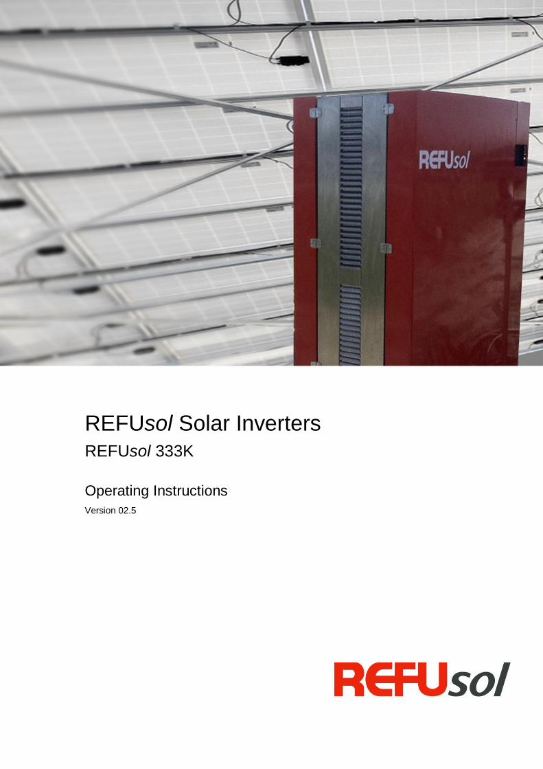
REFUsol Solar Inverters
REFUsol 333K
Operating Instructions
Version 02.5
REFUsol Photovoltaic Inverter REFUsol 333K
Operating Instructions
Version 01 (Provisional as at 06.06.2012)
BA_REFUSOL333K_V02.5_EN
2
Title REFUsol Photovoltaic Inverter
REFUsol 333K
Type of Documentation Operating Instructions
Purpose of
Documentation
This document explains the REFUsol 333K.
It provides information
on operating the product,
on error messages and possible causes, as well as details on how to
correct errors.
Published by
REFUsol GmbH
Uracher Straße 91 D-72555 Metzingen
www.refusol.com
Legal Disclaimer
All details in this documentation have been compiled and checked
with the utmost care. Nevertheless, faults or deviations based on technical progress cannot be completely excluded. We therefore accept no liability for completeness or correctness.
The relevant up-to-date version can be obtained from www.refusol.com.
Copyright
The information contained in this documentation is the property of REFUsol GmbH. Using and publicizing this documentation, including
only extracts, requires the written consent of REFUsol GmbH.
Trademark REFUsol® is a registered trademark of REFUsol GmbH.
Issue ID Remarks
BA_REFUSOL333K_V02.5_EN Last updated 2013/09
BA_REFUSOL333K_V02.5_EN
3
Table of Contents
1 0BAbout these Operating Instructions......................................................................................5
1.1 12BSymbols and Markup ...................................................................................................5
1.2 Warning Notices ..........................................................................................................5
1.2.1 50BLayout of a Warning Notice .........................................................................................5
1.2.2 Categories of Warning Notices ....................................................................................5
1.3 13BInformation ..................................................................................................................6
2 1BSafety Information .................................................................................................................7
2.1 14BIntroduction .................................................................................................................7
2.2 15BProper Usage ..............................................................................................................7
2.3 17BTarget Group ...............................................................................................................7
2.4 6BPersonnel Requirements .............................................................................................7
2.5 Disclaimer ...................................................................................................................7
2.6 18BPreventing Electric Shock ............................................................................................8
2.7 Protection against Electrostatic Discharge (ESD) .........................................................8
2.8 19BProtection against Magnetic and Electromagnetic Fields during Operation and
Assembly .................................................................................................................................8
2.9 20BPreventing Burns Caused by Contact with Hot Parts ....................................................9
2.10 21BProtection during Handling and Assembly ....................................................................9
2.11 Disposal .................................................................................................................... 10
2.12 23BFeed-in and grid safety management......................................................................... 10
3 2BDescription of the REFUsol 333K ........................................................................................ 11
3.1 24BHow It Works ............................................................................................................. 11
3.2 25BBasic Design ............................................................................................................. 12
3.3 26BGraphical display and control panel ........................................................................... 13
3.4 32BStandard Display ....................................................................................................... 14
3.5 Yield Data Display ..................................................................................................... 15
3.6 Standardized Yield Data Display................................................................................ 15
3.7 33BOverview of Menus.................................................................................................... 17
3.8 Password Entry ......................................................................................................... 20
3.9 27BInternal Data Logger .................................................................................................. 21
4 3BDecommissioning and Recommissioning the Inverter ...................................................... 22
4.1 Use of the discharge unit PM932 ............................................................................... 22
4.2 Disconnection / connection of the supply voltage ....................................................... 23
4.2.1 Switching off the Supply Voltage ............................................................................... 23
4.2.2 Switching on the Supply Voltage ............................................................................... 24
4.3 Automatic Activation of Feed-In ................................................................................. 25
4.4 Switching off Feed-In ................................................................................................. 27
BA_REFUSOL333K_V02.5_EN
4
5 5BTroubleshooting .................................................................................................................. 28
5.1 39BSelf-Test Error Messages .......................................................................................... 28
5.2 40BTransient Failure ....................................................................................................... 28
5.3 41BFaults ........................................................................................................................ 28
5.4 42BAcknowledging Faults................................................................................................ 28
5.5 Return of the solar inverter ........................................................................................ 28
5.6 43BList of Fault Messages............................................................................................... 29
6 6BMaintenance and Cleaning .................................................................................................. 35
6.1 44BMaintenance Instructions ........................................................................................... 35
7 7BTechnical Data ..................................................................................................................... 36
7.1 45BTechnical Specifications for REFUsol 333k Solar Inverter ......................................... 36
7.2 Dimensions of REFUsol 333k Solar Inverter ............................................................. 38
7.3 8BDecommissioning/Deinstallation ................................................................................ 39
7.4 48BDecommissioning and Deinstalling the Solar Inverter ................................................. 39
7.5 49BDisposing of the Inverter ............................................................................................ 39
8 9BContact ................................................................................................................................. 40
9 10BCertificates ........................................................................................................................... 41
10 11BNote ...................................................................................................................................... 42
BA_REFUSOL333K_V02.5_EN
5
1 0BAbout these Operating Instructions These operating instructions form part of the product
Read the operating instructions carefully before using the product.
Keep the operating instructions readily available with the device for the entire service life of
the product.
Provide all future users of the device access to the operating instructions.
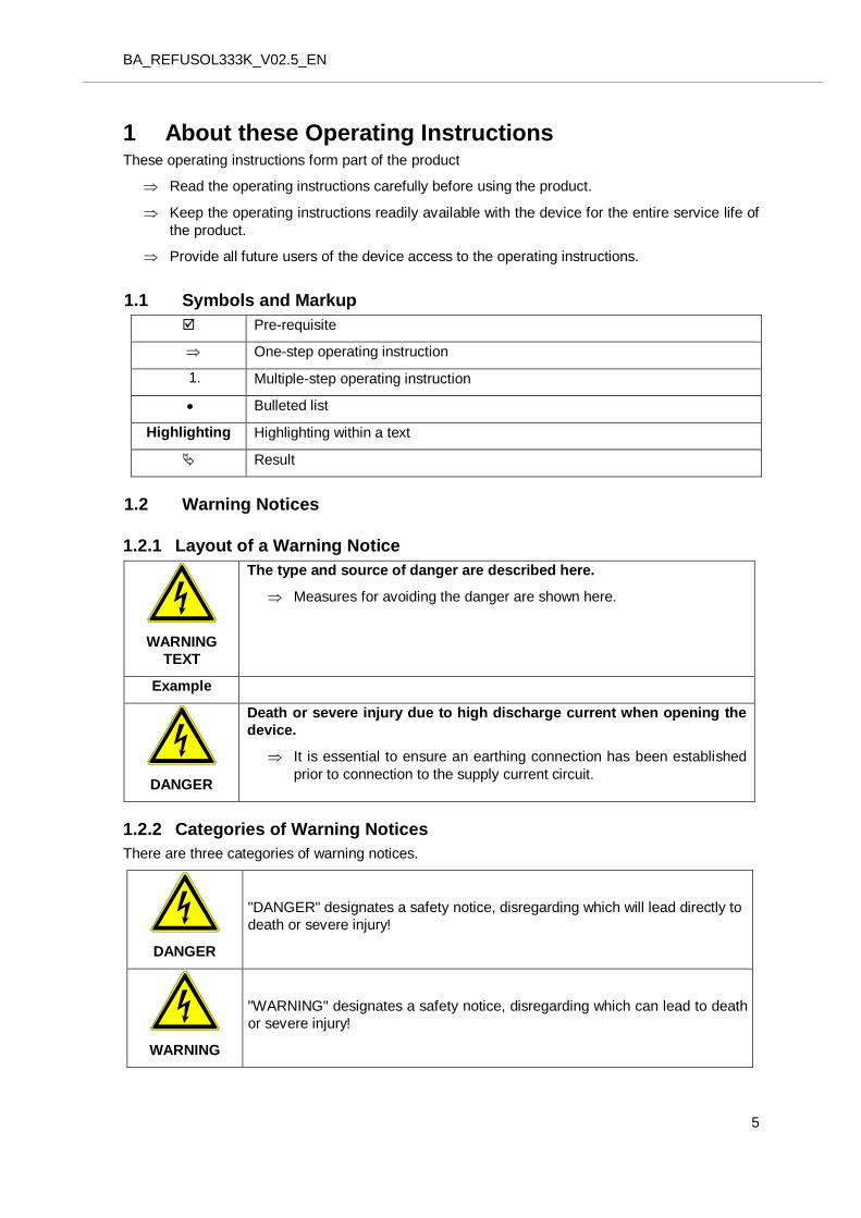
1.1 12BSymbols and Markup
Pre-requisite
One-step operating instruction
1. Multiple-step operating instruction
Bulleted list
Highlighting Highlighting within a text
Result
1.2 Warning Notices
1.2.1 50BLayout of a Warning Notice
WARNING
TEXT
The type and source of danger are described here.
Measures for avoiding the danger are shown here.
Example
DANGER
Death or severe injury due to high discharge current when opening the
device.
It is essential to ensure an earthing connection has been established
prior to connection to the supply current circuit.
1.2.2 Categories of Warning Notices
There are three categories of warning notices.
DANGER
"DANGER" designates a safety notice, disregarding which will lead directly to
death or severe injury!
WARNING
"WARNING" designates a safety notice, disregarding which can lead to death
or severe injury!
BA_REFUSOL333K_V02.5_EN
6
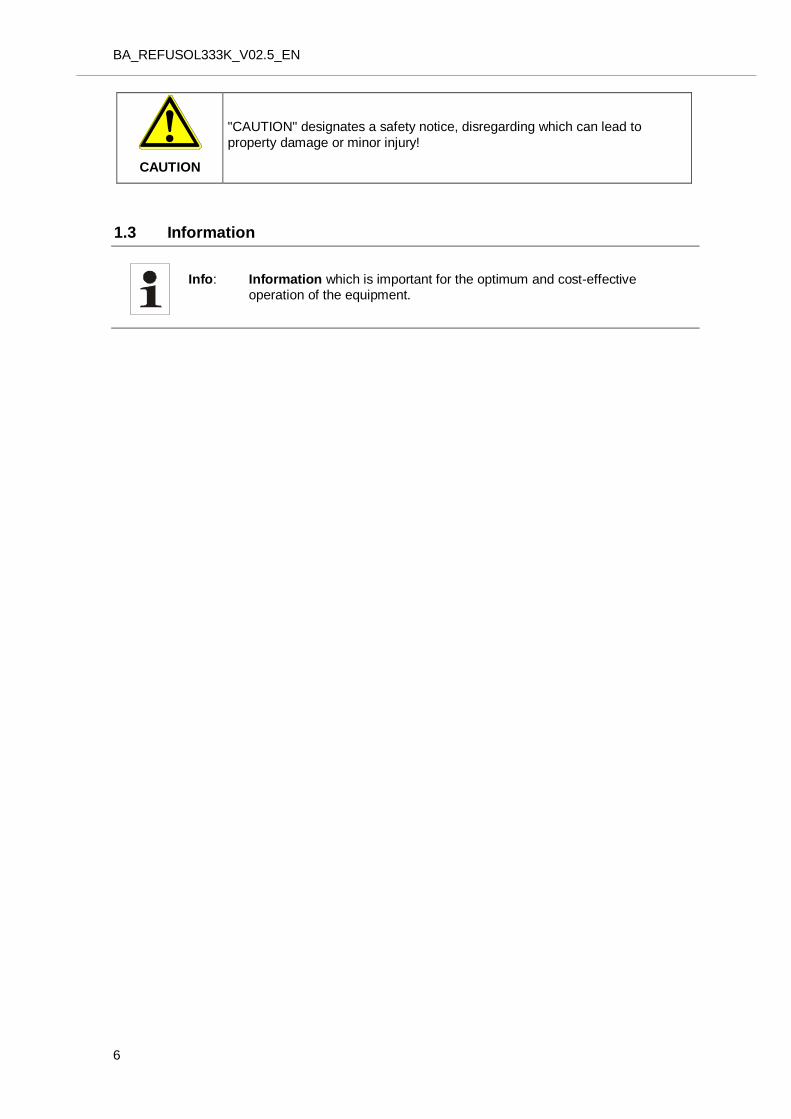
CAUTION
"CAUTION" designates a safety notice, disregarding which can lead to
property damage or minor injury!
1.3 13BInformation
Info: Information which is important for the optimum and cost-effective operation of the equipment.
BA_REFUSOL333K_V02.5_EN
7
2 1BSafety Information
2.1 14BIntroduction
The following instructions must be followed before operating the system for the first time in order to
prevent injury or damage to property. Safety instructions must be complied with at all times.
Before operating the device for the first time, carefully read all the documentation provided.
If the device is sold, rented or otherwise passed on, these safety instructions must also be given to
the next user.
2.2 15BProper Usage
The REFUsol photovoltaic inverter transforms the direct current generated by photovoltaic (PV)
modules into alternating current and feeds this into the grid. The device may only feed into the
medium-voltage network via a galvanically isolating Transformatior. Any use beyond this is not
deemed to be proper. The manufacture will accept no liability for any damage resulting in this
respect and the user alone will bear all responsibility. The REFUsol photovoltaic inverter has been constructed according to the current state of
technology and in line with the rules of technical safety. For simplification purposes, the REFUsol photovoltaic inverter is also referred to as the “inverter” in
these instructions.
2.3 17BTarget Group
These operating instructions are intended for:
Qualified electricians
2.4 6BPersonnel Requirements
For the purposes of this document, qualified electricians are individuals who have the specialist training, experience, and knowledge of the relevant regulations to be able to assess the work assigned to them and identify potential dangers.
2.5 Disclaimer
The REFUsol GmbH General Terms & Conditions for the Supply of Goods and Services apply.
In the event of loss or damage resulting from failure to comply with the warnings in these
operating instructions or improper use REFUsol GmbH accepts no liability.
Before operating the system for the first time, carefully read through the operating,
maintenance, and safety instructions.
Qualified electricians are responsible for ensuring compliance with currently applicable
standards and legal requirements, such as: standard 60364-7-712:2005: Requirements for
special installations or locations – Solar photovoltaic power supply systems.
Problem-free and safe operation of the device requires proper and specialized transportation,
storage, assembly, and installation as well as careful operation and maintenance.
Only use accessories and spare parts approved by the manufacturer.
Adherence must be ensured to the safety rules and regulations that apply in the country where
the system will be used.
The ambient conditions stated in the product documentation must be observed.
For European countries, EU Directive 2004/108/EC (EMC Directive) must be observed when
BA_REFUSOL333K_V02.5_EN
8
using the inverter.
The technical data, rating, connection, and installation conditions must be noted from the
product documentation and observed under all circumstances.
We accept no liability in the event of loss or damage associated with a force majeure event or
disaster.
2.6 18BPreventing Electric Shock
DANGER
Danger to life from electric shock. Persistently high electric voltage in terminals and lines, even after device has been isolated and switched off.
It is essential to ensure an earthing connection has been established prior to connection to the supply current circuit.
Carefully check for correct connections.
Minimum requirements for measuring instruments comply with: Voltage: AC = 1000 V / DC = 1500 V Measurement Category: 1000 V CAT IV Degree of protection: IP55 (suitable for outdoor use)
2.7 Protection against Electrostatic Discharge (ESD)
CAUTION
Electrostatic discharge can damage or destroy electronic assemblies.
The appropriate ESD protection regulations must be noted and adhered to
when working on the device.
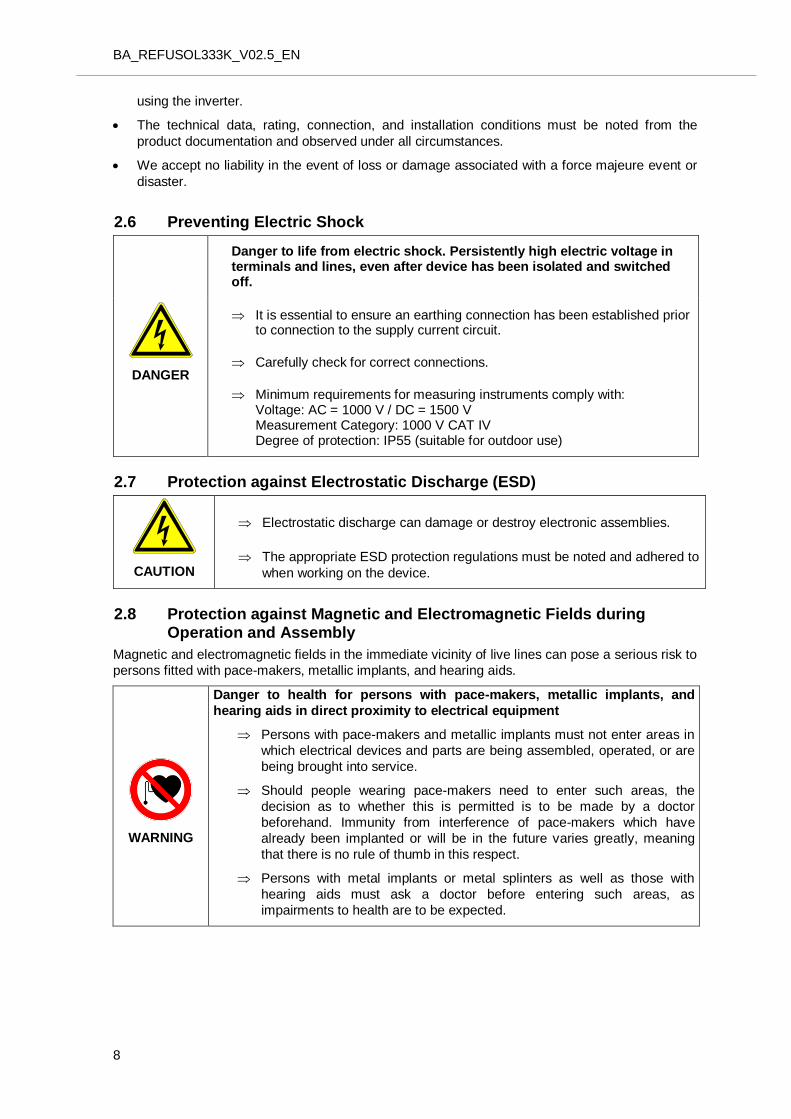
2.8 19BProtection against Magnetic and Electromagnetic Fields during Operation and Assembly
Magnetic and electromagnetic fields in the immediate vicinity of live lines can pose a serious risk to
persons fitted with pace-makers, metallic implants, and hearing aids.
WARNING
Danger to health for persons with pace-makers, metallic implants, and
hearing aids in direct proximity to electrical equipment
Persons with pace-makers and metallic implants must not enter areas in
which electrical devices and parts are being assembled, operated, or are
being brought into service.
Should people wearing pace-makers need to enter such areas, the
decision as to whether this is permitted is to be made by a doctor
beforehand. Immunity from interference of pace-makers which have
already been implanted or will be in the future varies greatly, meaning
that there is no rule of thumb in this respect.
Persons with metal implants or metal splinters as well as those with
hearing aids must ask a doctor before entering such areas, as
impairments to health are to be expected.
BA_REFUSOL333K_V02.5_EN
9
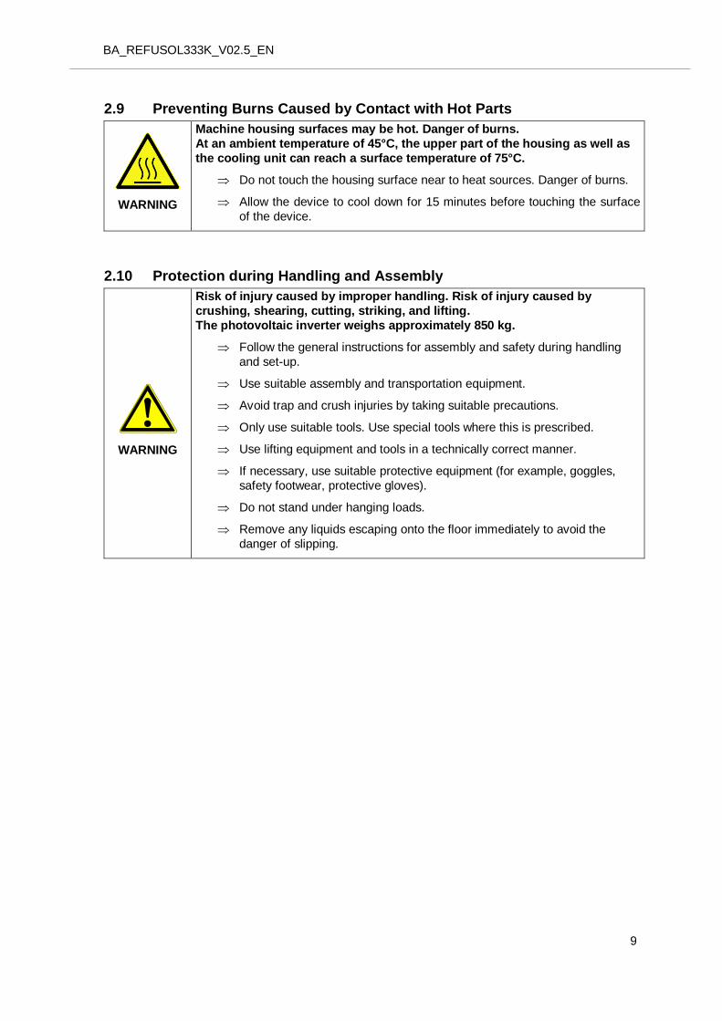
2.9 20BPreventing Burns Caused by Contact with Hot Parts
WARNING
Machine housing surfaces may be hot. Danger of burns.
At an ambient temperature of 45°C, the upper part of the housing as well as
the cooling unit can reach a surface temperature of 75°C.
Do not touch the housing surface near to heat sources. Danger of burns.
Allow the device to cool down for 15 minutes before touching the surface
of the device.
2.10 21BProtection during Handling and Assembly
WARNING
Risk of injury caused by improper handling. Risk of injury caused by
crushing, shearing, cutting, striking, and lifting.
The photovoltaic inverter weighs approximately 850 kg.
Follow the general instructions for assembly and safety during handling
and set-up.
Use suitable assembly and transportation equipment.
Avoid trap and crush injuries by taking suitable precautions.
Only use suitable tools. Use special tools where this is prescribed.
Use lifting equipment and tools in a technically correct manner.
If necessary, use suitable protective equipment (for example, goggles,
safety footwear, protective gloves).
Do not stand under hanging loads.
Remove any liquids escaping onto the floor immediately to avoid the
danger of slipping.

BA_REFUSOL333K_V02.5_EN
10
2.11 Disposal
2.12 23BFeed-in and grid safety management
Feed-in and grid management is designated as the interactive control of the inverter by the grid operator.
According to provisions of Sec. 11 of the Renewable Energies Act (2012 version) in Germany, grid-connected PV systems must participate in feed-in and grid safety management.
This primarily involves the possibility for the grid operator to temporarily limit the PV system remotely, and even to reduce it to null in critical situations for a short period.
In such cases, the REFUpmu (power management unit) and the photovoltaic inverter are to be connected with one another by way of interface RS485. The connection to the portal or modem/router takes place via an Ethernet connection. .
Dispose of the packaging and replaced parts according
to the rules applicable in the country where the device is
installed.
Do not dispose of the REFUsol photovoltaic inverter with normal domestic waste.
The photovoltaic inverter complies with the RoHS Directive.
That means that the device can be taken to municipal disposal
sites for household appliances.
REFUsol GmbH will take back the photovoltaic inverter
completely. Please contact the Service team!
BA_REFUSOL333K_V02.5_EN
11
3 2BDescription of the REFUsol 333K
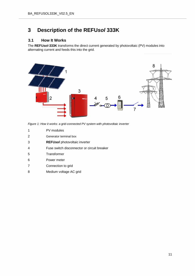
3.1 24BHow It Works
The REFUsol-333K transforms the direct current generated by photovoltaic (PV) modules into
alternating current and feeds this into the grid.
Figure 1: How it works: a grid-connected PV system with photovoltaic inverter
1 PV modules
2 Generator terminal box
3 REFUsol photovoltaic inverter
4 Fuse switch disconnector or circuit breaker
5 Transformer
6 Power meter
7 Connection to grid
8 Medium voltage AC grid
BA_REFUSOL333K_V02.5_EN
12
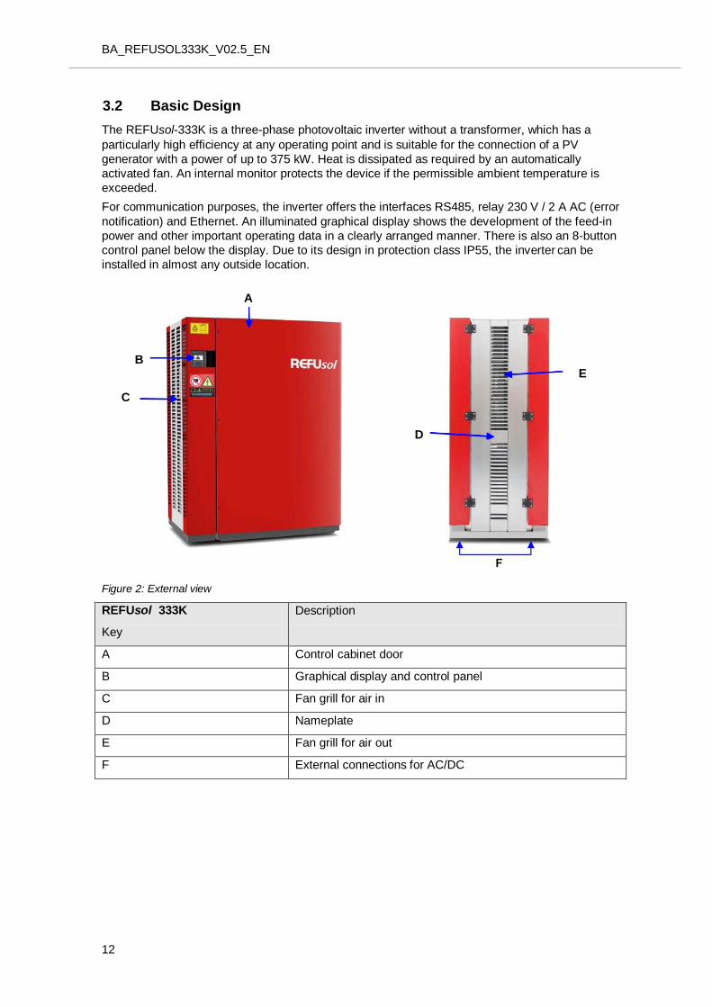
3.2 25BBasic Design
The REFUsol-333K is a three-phase photovoltaic inverter without a transformer, which has a
particularly high efficiency at any operating point and is suitable for the connection of a PV
generator with a power of up to 375 kW. Heat is dissipated as required by an automatically
activated fan. An internal monitor protects the device if the permissible ambient temperature is
exceeded.
For communication purposes, the inverter offers the interfaces RS485, relay 230 V / 2 A AC (error
notification) and Ethernet. An illuminated graphical display shows the development of the feed-in
power and other important operating data in a clearly arranged manner. There is also an 8-button
control panel below the display. Due to its design in protection class IP55, the inverter can be
installed in almost any outside location.
Figure 2: External view
REFUsol 333K
Key
Description
A Control cabinet door
B Graphical display and control panel
C Fan grill for air in
D Nameplate
E Fan grill for air out
F External connections for AC/DC
C
B
A
E
D
BA_REFUSOL333K_V02.5_EN
13
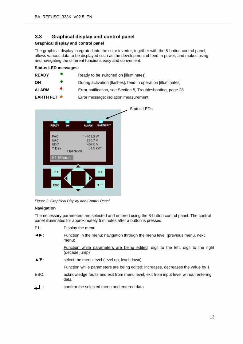
3.3 26BGraphical display and control panel
Graphical display and control panel
The graphical display integrated into the solar inverter, together with the 8-button control panel,
allows various data to be displayed such as the development of feed-in power, and makes using
and navigating the different functions easy and convenient.
Status LED messages:
READY Ready to be switched on [illuminates]
ON During activation [flashes], feed-in operation [illuminates]
ALARM Error notification, see Section 5, Troubleshooting, page 28
EARTH FLT Error message: isolation measurement
Figure 3: Graphical Display and Control Panel
Navigation
The necessary parameters are selected and entered using the 8-button control panel. The control
panel illuminates for approximately 5 minutes after a button is pressed.
F1: Display the menu
◄►: Function in the menu: navigation through the menu level (previous menu, next
menu)
Function while parameters are being edited: digit to the left, digit to the right
(decade jump)
▲▼: select the menu level (level up, level down)
Function while parameters are being edited: increases, decreases the value by 1
ESC: acknowledge faults and exit from menu level, exit from input level without entering
data
: confirm the selected menu and entered data
Status LEDs
BA_REFUSOL333K_V02.5_EN
14
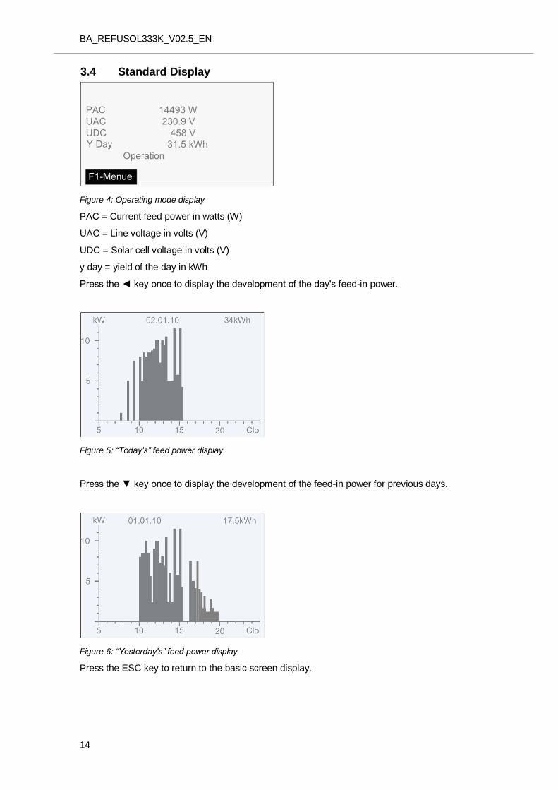
3.4 32BStandard Display
Figure 4: Operating mode display
PAC = Current feed power in watts (W)
UAC = Line voltage in volts (V)
UDC = Solar cell voltage in volts (V)
y day = yield of the day in kWh
Press the ◄ key once to display the development of the day's feed-in power.
Figure 5: “Today's” feed power display
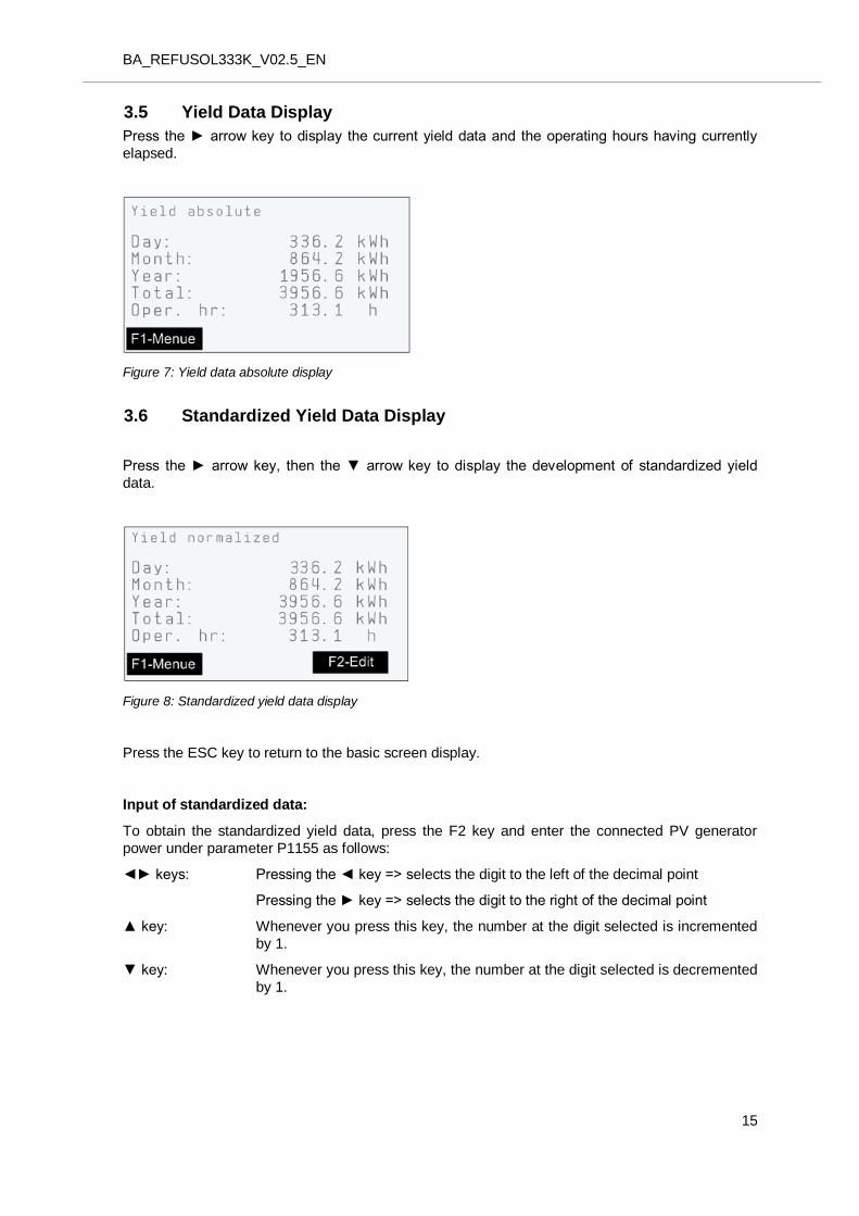
Press the ▼ key once to display the development of the feed-in power for previous days.
Figure 6: “Yesterday's” feed power display
Press the ESC key to return to the basic screen display.
BA_REFUSOL333K_V02.5_EN
15
3.5 Yield Data Display
Press the ► arrow key to display the current yield data and the operating hours having currently
elapsed.
Figure 7: Yield data absolute display
3.6 Standardized Yield Data Display
Press the ► arrow key, then the ▼ arrow key to display the development of standardized yield
data.
Figure 8: Standardized yield data display
Press the ESC key to return to the basic screen display.
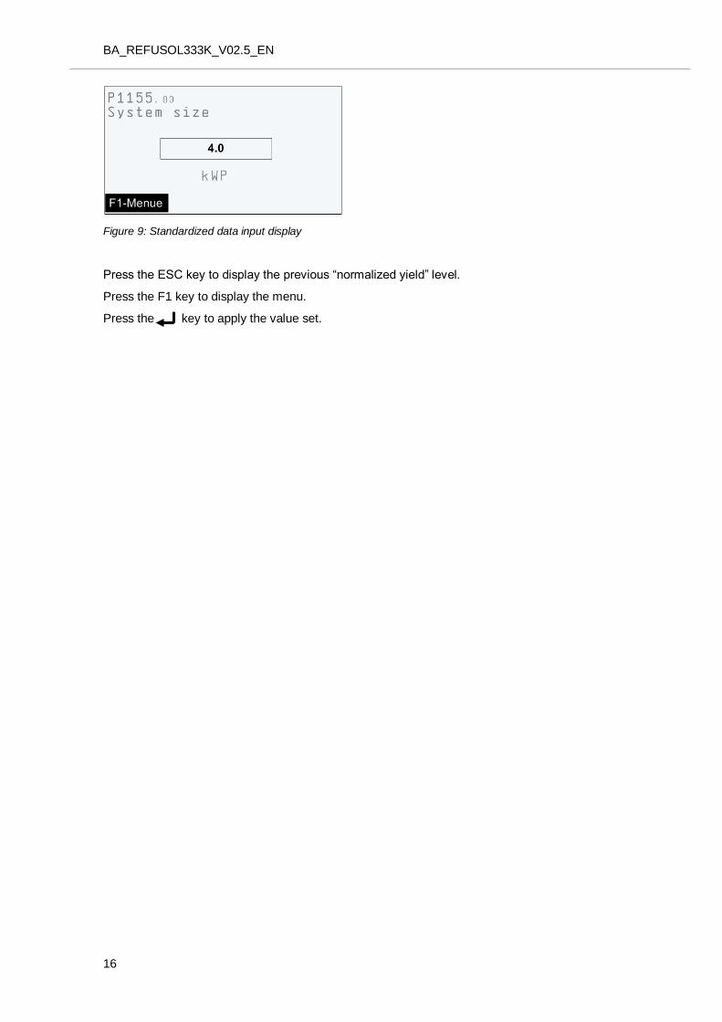
Input of standardized data:
To obtain the standardized yield data, press the F2 key and enter the connected PV generator
power under parameter P1155 as follows:
◄► keys: Pressing the ◄ key => selects the digit to the left of the decimal point
Pressing the ► key => selects the digit to the right of the decimal point
▲ key: Whenever you press this key, the number at the digit selected is incremented
by 1.
▼ key: Whenever you press this key, the number at the digit selected is decremented
by 1.
BA_REFUSOL333K_V02.5_EN
16
Figure 9: Standardized data input display
Press the ESC key to display the previous “normalized yield” level.
Press the F1 key to display the menu.
Press the key to apply the value set.
BA_REFUSOL333K_V02.5_EN
17
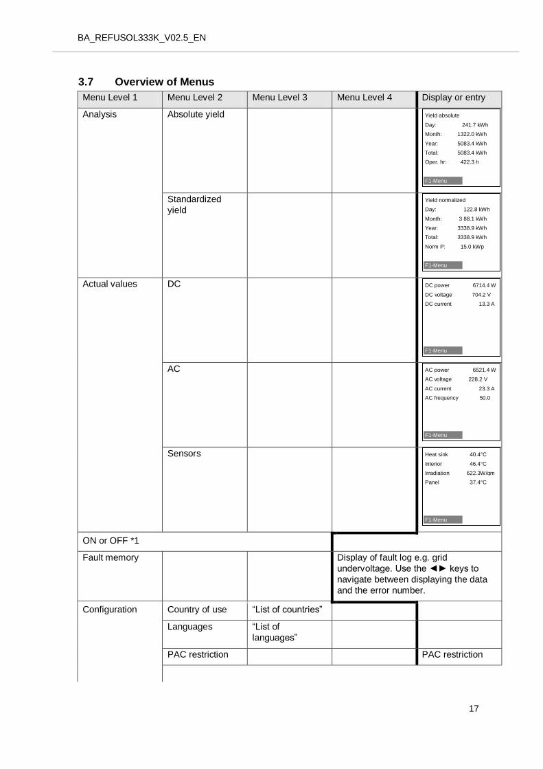
3.7 33BOverview of Menus
Menu Level 1 Menu Level 2 Menu Level 3 Menu Level 4 Display or entry
Analysis Absolute yield
Standardized
yield
Actual values DC
AC
Sensors
ON or OFF *1
Fault memory Display of fault log e.g. grid
undervoltage. Use the ◄► keys to
navigate between displaying the data
and the error number.
Configuration Country of use “List of countries”
Languages “List of
languages”
PAC restriction PAC restriction
Heat sink 40.4°C
Interior 46.4°C
Irradiation 622.3W/qm
Panel 37.4°C
F1-Menu
AC power 6521.4 W
AC voltage 228.2 V
AC current 23.3 A
AC frequency 50.0 Hz
F1-Menu
DC power 6714.4 W
DC voltage 704.2 V
DC current 13.3 A
F1-Menu
Yield normalized
Day: 122.8 kWh
Month: 3 88.1 kWh
Year: 3338.9 kWh
Total: 3338.9 kWh
Norm P: 15.0 kWp
F1-Menu
Yield absolute
Day: 241.7 kWh
Month: 1322.0 kWh
Year: 5083.4 kWh
Total: 5083.4 kWh
Oper. hr: 422.3 h
F1-Menu
BA_REFUSOL333K_V02.5_EN
18
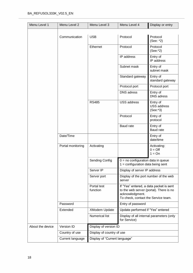
Menu Level 1 Menu Level 2 Menu Level 3 Menu Level 4 Display or entry
Communication USB Protocol Protocol
(See: *2)
Ethernet Protocol Protocol
(See:*2)
IP address Entry of
IP address
Subnet mask Entry of
subnet mask
Standard gateway Entry of
standard gateway
Protocol port Protocol port
DNS adress Entry of
DNS adress
RS485 USS address Entry of
USS address
(See:*3)
Protocol Entry of
protocol
Baud rate Entry of
Baud rate
Date/Time Entry of
date/time
Portal monitoring Activating Activating:
0 = Off
1 = On
Sending Config 0 = no configuration data in queue
1 = configuration data being sent
Server IP Display of server IP address
Server port Display of the port number of the web
server
Portal test
function
If “Yes” entered, a data packet is sent
to the web server (portal). There is no
acknowledgment.
To check, contact the Service team.
Password Entry of password
Extended XModem Update Update performed if “Yes” entered
Numerical list Display of all internal parameters (only
for Service)
About the device Version ID Display of version ID
Country of use Display of country of use
Current language Display of “Current language”
BA_REFUSOL333K_V02.5_EN
19
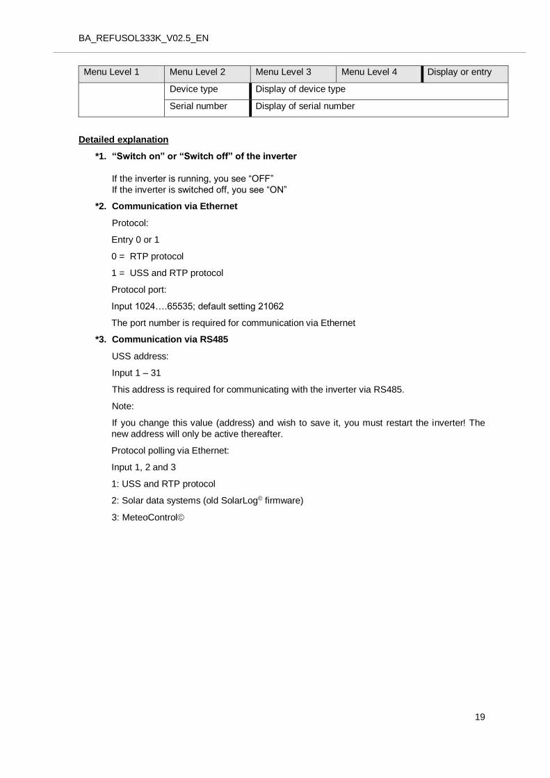
Menu Level 1 Menu Level 2 Menu Level 3 Menu Level 4 Display or entry
Device type Display of device type
Serial number Display of serial number
Detailed explanation
*1. “Switch on” or “Switch off” of the inverter
If the inverter is running, you see “OFF”
If the inverter is switched off, you see “ON”
*2. Communication via Ethernet
Protocol:
Entry 0 or 1
0 = RTP protocol
1 = USS and RTP protocol
Protocol port:
Input 1024….65535; default setting 21062
The port number is required for communication via Ethernet
*3. Communication via RS485
USS address:
Input 1 – 31
This address is required for communicating with the inverter via RS485.
Note:
If you change this value (address) and wish to save it, you must restart the inverter! The
new address will only be active thereafter.
Protocol polling via Ethernet:
Input 1, 2 and 3
1: USS and RTP protocol
2: Solar data systems (old SolarLog© firmware)
3: MeteoControl
BA_REFUSOL333K_V02.5_EN
20
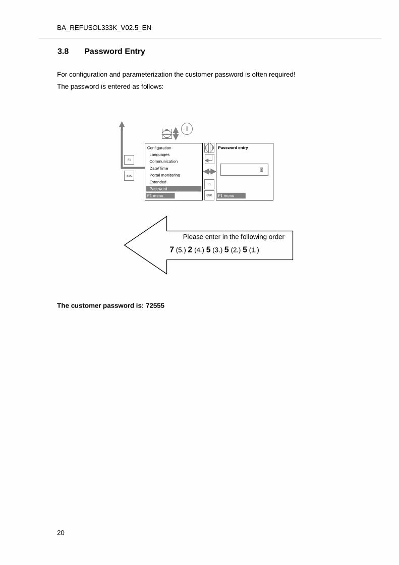
3.8 Password Entry
For configuration and parameterization the customer password is often required!
The password is entered as follows:
The customer password is: 72555
Please enter in the following order
7 (5.) 2 (4.) 5 (3.) 5 (2.) 5 (1.)
Configuration
Languages
Communication
Date/Time
Portal monitoring
Extended
Password
F1 menu
Password entry
F1 menu
0
ESC
F1
F1
ESC
I
BA_REFUSOL333K_V02.5_EN
21
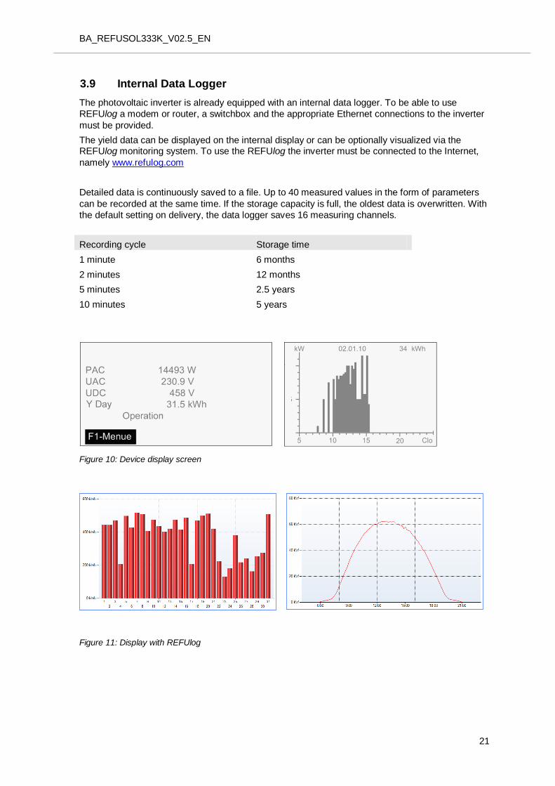
3.9 27BInternal Data Logger
The photovoltaic inverter is already equipped with an internal data logger. To be able to use
REFUlog a modem or router, a switchbox and the appropriate Ethernet connections to the inverter
must be provided.
The yield data can be displayed on the internal display or can be optionally visualized via the REFUlog monitoring system. To use the REFUlog the inverter must be connected to the Internet,
namely www.refulog.com
Detailed data is continuously saved to a file. Up to 40 measured values in the form of parameters
can be recorded at the same time. If the storage capacity is full, the oldest data is overwritten. With
the default setting on delivery, the data logger saves 16 measuring channels.
Recording cycle Storage time
1 minute 6 months
2 minutes 12 months
5 minutes 2.5 years
10 minutes 5 years
Figure 10: Device display screen
Figure 11: Display with REFUlog
BA_REFUSOL333K_V02.4_EN
22
4 3BDecommissioning and Recommissioning the Inverter
DANGER
Danger to life caused by persistently high electric voltage in terminals
and lines, even after the inverter has been isolated and switched off.
No emergency shutdown on solar inverter.
The solar inverter is galvanically isolated from the PV system via DC switch disconnectors in the connected GAKs*.
The solar inverter is galvanically isolated from the AC mains via a fuse
switch disconnector or circuit breaker on the transformer.
Work on the REFUsol 333K is only permitted after all phases have
been disconnected on the AC and DC side of the device.
If work is to be performed inside the REFUsol 333K, the DC link
capacitors must be manually discharged.
Manual discharging of DC link capacitors may be performed only by
suitably trained and authorized personnel, and using the discharge
unit PM932.
*GAK = Generator terminal box
Before using the inverter for the first time, the device must be set up for operation and all requirements met as described in the installation instructions for the REFUsol 333K.
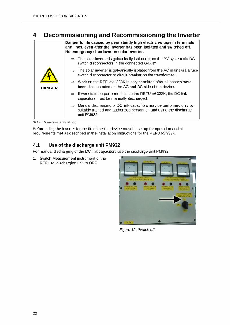
4.1 Use of the discharge unit PM932
For manual discharging of the DC link capacitors use the discharge unit PM932.
1. Switch Measurement instrument of the
REFUsol discharging unit to OFF.
Figure 12: Switch off
BA_REFUSOL333K_V02.5_EN
23
2. Fix REFUsol discharging unit at terminal area.
Figure 13: Fix discharge unit
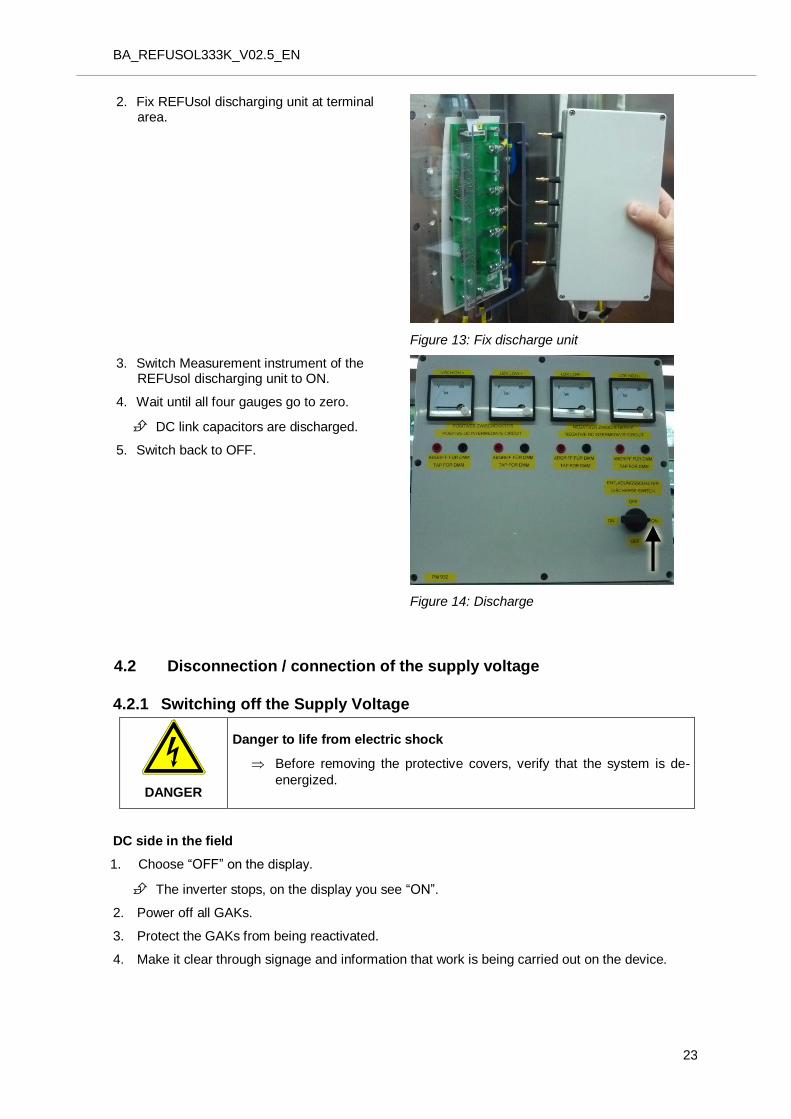
3. Switch Measurement instrument of the REFUsol discharging unit to ON.
4. Wait until all four gauges go to zero.
DC link capacitors are discharged.
5. Switch back to OFF.
Figure 14: Discharge
4.2 Disconnection / connection of the supply voltage
4.2.1 Switching off the Supply Voltage
DANGER
Danger to life from electric shock
Before removing the protective covers, verify that the system is de-
energized.
DC side in the field
1. Choose “OFF” on the display.
The inverter stops, on the display you see “ON”.
2. Power off all GAKs.
3. Protect the GAKs from being reactivated.
4. Make it clear through signage and information that work is being carried out on the device.
BA_REFUSOL333K_V02.4_EN
24
AC distribution
5. Switch off accompanying fuse switch disconnectors.
6. Remove fuses and store in a safe place.
7. Ensure the device cannot be reactivated.
8. Make it clear through signage and information that work is being carried out on the device.
On the REFUsol 333K AC side
9. Verify connection points are de-energized.
10. Remove protective covers.
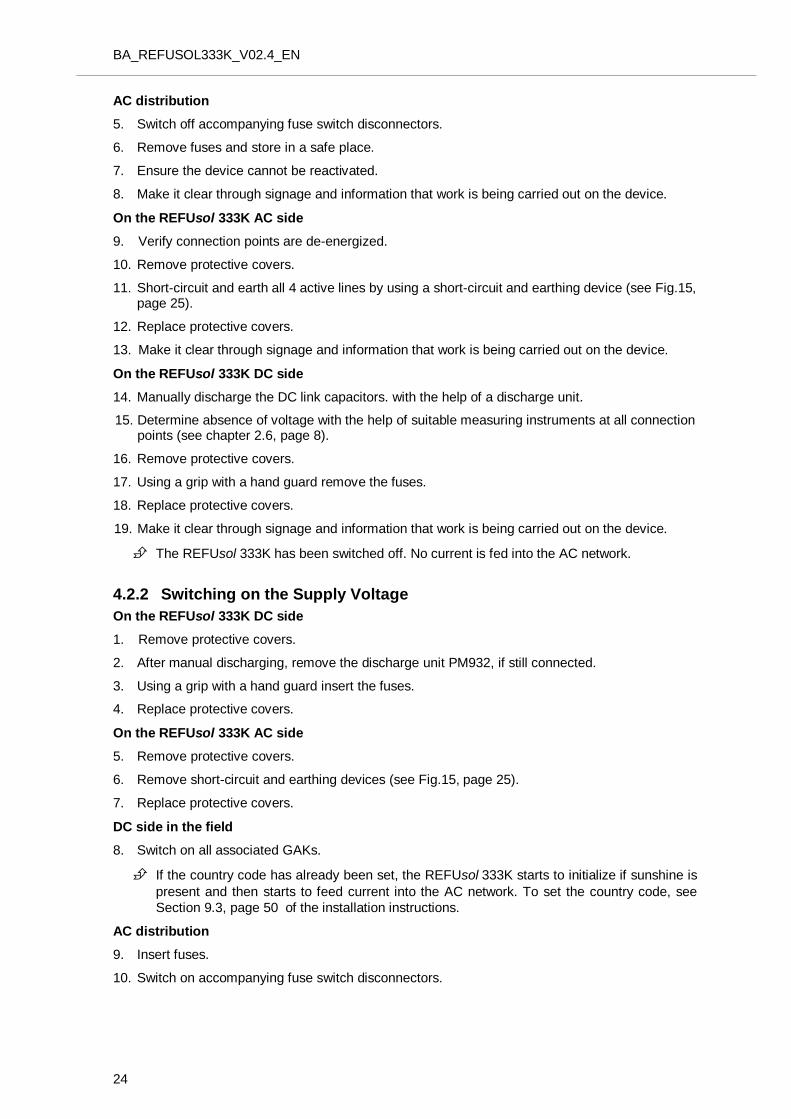
11. Short-circuit and earth all 4 active lines by using a short-circuit and earthing device (see Fig.15, page 25).
12. Replace protective covers.
13. Make it clear through signage and information that work is being carried out on the device.
On the REFUsol 333K DC side
14. Manually discharge the DC link capacitors. with the help of a discharge unit.
15. Determine absence of voltage with the help of suitable measuring instruments at all connection points (see chapter 2.6, page 8).
16. Remove protective covers.
17. Using a grip with a hand guard remove the fuses.
18. Replace protective covers.
19. Make it clear through signage and information that work is being carried out on the device.
The REFUsol 333K has been switched off. No current is fed into the AC network.
4.2.2 Switching on the Supply Voltage
On the REFUsol 333K DC side
1. Remove protective covers.
2. After manual discharging, remove the discharge unit PM932, if still connected.
3. Using a grip with a hand guard insert the fuses.
4. Replace protective covers.
On the REFUsol 333K AC side
5. Remove protective covers.
6. Remove short-circuit and earthing devices (see Fig.15, page 25).
7. Replace protective covers.
DC side in the field
8. Switch on all associated GAKs.
If the country code has already been set, the REFUsol 333K starts to initialize if sunshine is
present and then starts to feed current into the AC network. To set the country code, see
Section 9.3, page 50 of the installation instructions.
AC distribution
9. Insert fuses.
10. Switch on accompanying fuse switch disconnectors.
BA_REFUSOL333K_V02.5_EN
25
Figure 15: AC connector with screw on short-and earthing
4.3 Automatic Activation of Feed-In
As soon as the voltage systems have been switched on on the AC side and the DC side (see
Section 4.2.2), activation takes place automatically.
Provided that enough sunlight is reaching the solar modules and there are no faults, the procedure
below can be followed on the display:
Self-test:
All status LEDs are lit for approx. 6 seconds
The initialization cycle is started:
The “Ready” status LED flashes
Display:
PAC Feed power in watts (W)
UAC Line voltage in volts (V)
UDC Solar cell voltage in volts (V)
State Initialization
BA_REFUSOL333K_V02.4_EN
26
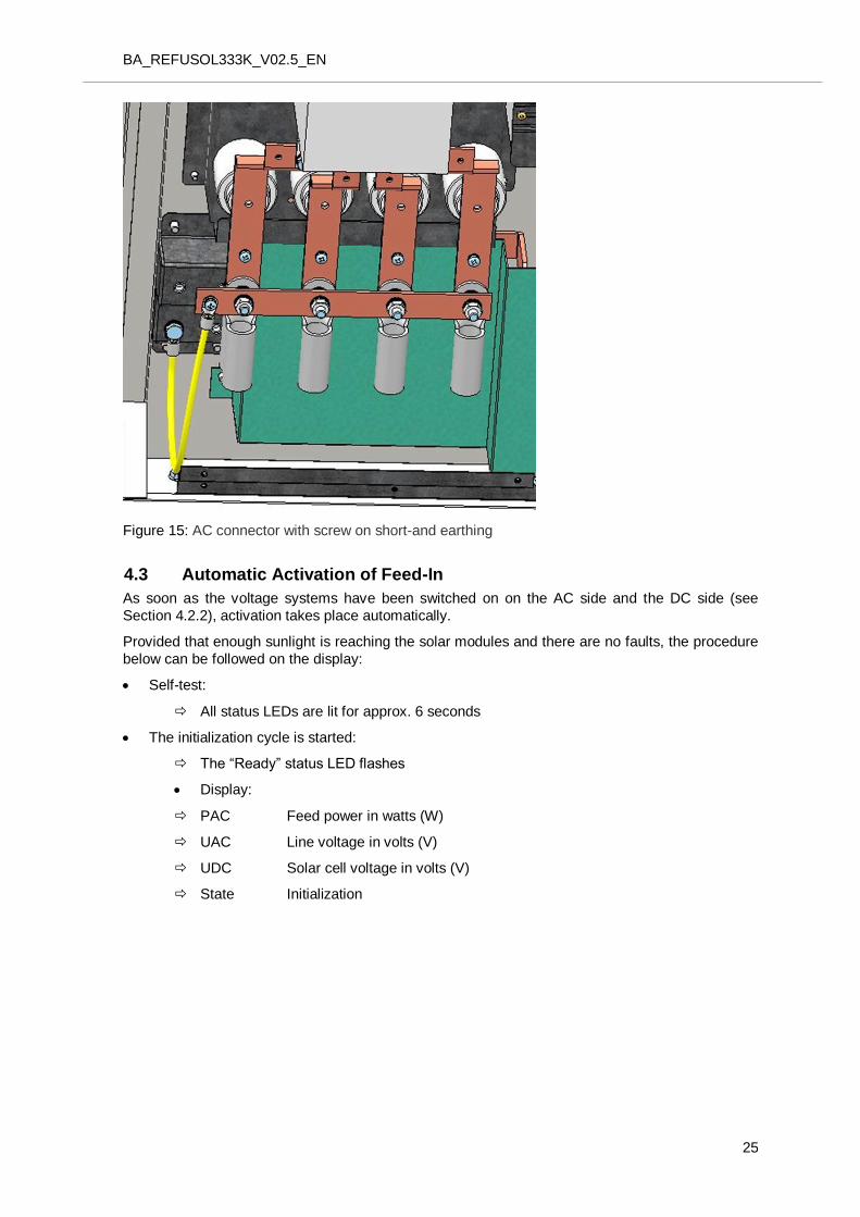
Figure 16: Device initialization display
Initializing has been completed:
The “READY” status LED remains illuminated
Display:
PAC Feed power in watts (W)
UAC Line voltage in volts (V)
UDC Solar cell voltage in volts (V)
Switched off
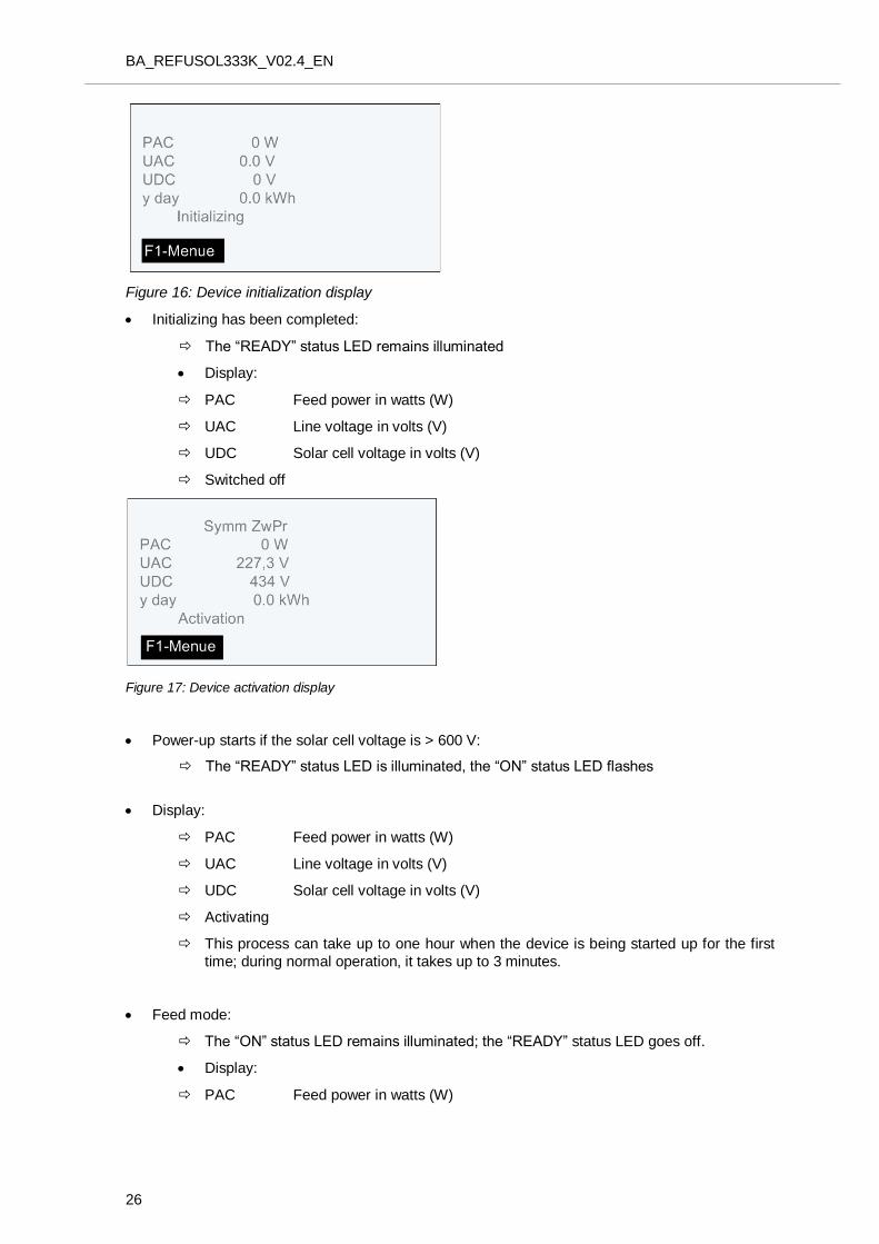
Figure 17: Device activation display
Power-up starts if the solar cell voltage is > 600 V:
The “READY” status LED is illuminated, the “ON” status LED flashes
Display:
PAC Feed power in watts (W)
UAC Line voltage in volts (V)
UDC Solar cell voltage in volts (V)
Activating
This process can take up to one hour when the device is being started up for the first
time; during normal operation, it takes up to 3 minutes.
Feed mode:
The “ON” status LED remains illuminated; the “READY” status LED goes off.
Display:
PAC Feed power in watts (W)
BA_REFUSOL333K_V02.5_EN
27
UAC Line voltage in volts (V)
UDC Solar cell voltage in volts (V)
y day = yield of the day in kWh
Operation
4.4 Switching off Feed-In
2. Select on the front panel of the graphic display “OFF”.
The inverter switches off; it appears "ON" on the display.
3. Shut down all affiliated generator junction boxes.
4. Secure them against reactivation.
BA_REFUSOL333K_V02.4_EN
28
5 5BTroubleshooting
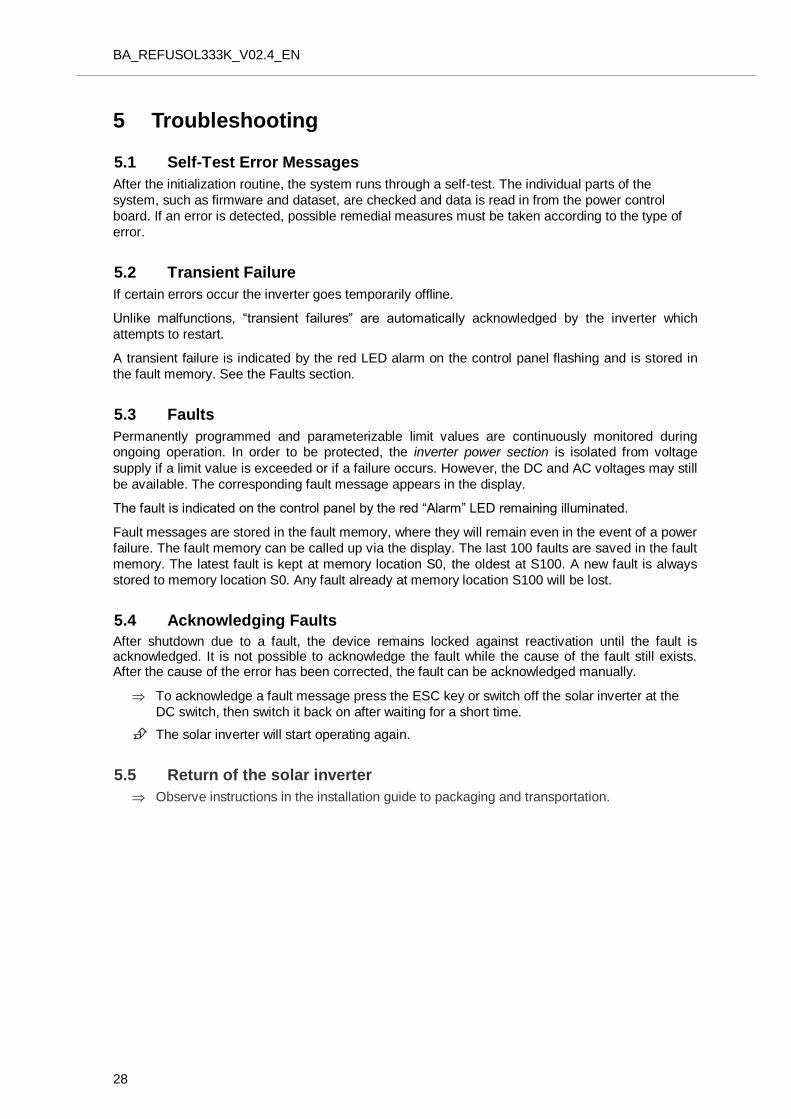
5.1 39BSelf-Test Error Messages
After the initialization routine, the system runs through a self-test. The individual parts of the
system, such as firmware and dataset, are checked and data is read in from the power control
board. If an error is detected, possible remedial measures must be taken according to the type of
error.
5.2 40BTransient Failure
If certain errors occur the inverter goes temporarily offline.
Unlike malfunctions, “transient failures” are automatically acknowledged by the inverter which
attempts to restart.
A transient failure is indicated by the red LED alarm on the control panel flashing and is stored in
the fault memory. See the Faults section.
5.3 41BFaults
Permanently programmed and parameterizable limit values are continuously monitored during ongoing operation. In order to be protected, the inverter power section is isolated from voltage
supply if a limit value is exceeded or if a failure occurs. However, the DC and AC voltages may still
be available. The corresponding fault message appears in the display.
The fault is indicated on the control panel by the red “Alarm” LED remaining illuminated.
Fault messages are stored in the fault memory, where they will remain even in the event of a power
failure. The fault memory can be called up via the display. The last 100 faults are saved in the fault
memory. The latest fault is kept at memory location S0, the oldest at S100. A new fault is always
stored to memory location S0. Any fault already at memory location S100 will be lost.
5.4 42BAcknowledging Faults
After shutdown due to a fault, the device remains locked against reactivation until the fault is acknowledged. It is not possible to acknowledge the fault while the cause of the fault still exists. After the cause of the error has been corrected, the fault can be acknowledged manually.
To acknowledge a fault message press the ESC key or switch off the solar inverter at the
DC switch, then switch it back on after waiting for a short time.
The solar inverter will start operating again.
5.5 Return of the solar inverter
Observe instructions in the installation guide to packaging and transportation.
BA_REFUSOL333K_V02.5_EN
29
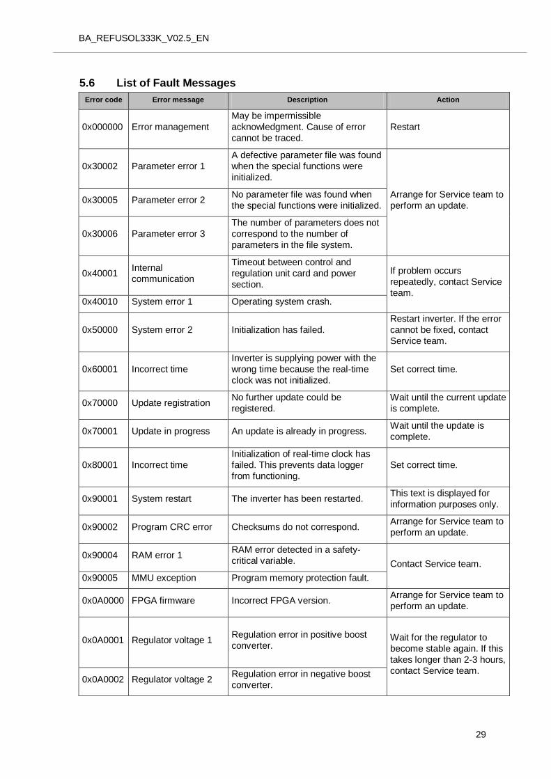
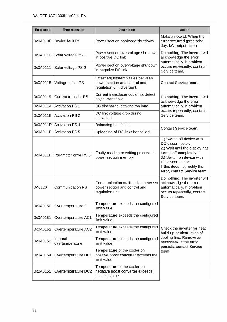
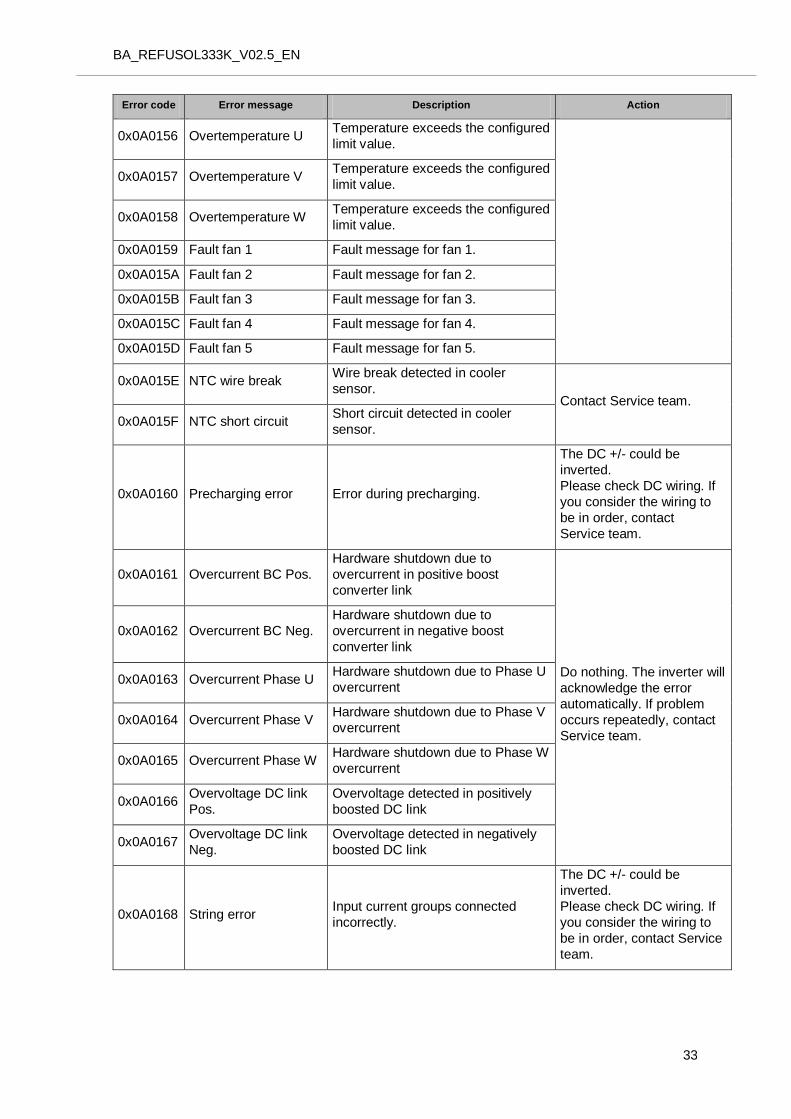
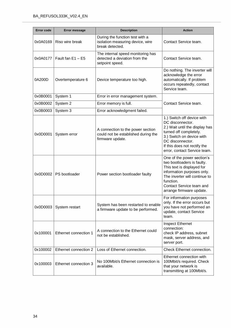
5.6 43BList of Fault Messages
Error code Error message Description Action
0x000000 Error management
May be impermissible
acknowledgment. Cause of error
cannot be traced.
Restart
0x30002 Parameter error 1
A defective parameter file was found
when the special functions were
initialized.
Arrange for Service team to
perform an update. 0x30005 Parameter error 2
No parameter file was found when
the special functions were initialized.
0x30006 Parameter error 3
The number of parameters does not
correspond to the number of
parameters in the file system.
0x40001 Internal
communication
Timeout between control and
regulation unit card and power
section.
If problem occurs
repeatedly, contact Service
team. 0x40010 System error 1 Operating system crash.
0x50000 System error 2 Initialization has failed.
Restart inverter. If the error
cannot be fixed, contact
Service team.
0x60001 Incorrect time
Inverter is supplying power with the
wrong time because the real-time
clock was not initialized.
Set correct time.
0x70000 Update registration No further update could be
registered.
Wait until the current update
is complete.
0x70001 Update in progress An update is already in progress. Wait until the update is
complete.
0x80001 Incorrect time
Initialization of real-time clock has
failed. This prevents data logger
from functioning.
Set correct time.
0x90001 System restart The inverter has been restarted. This text is displayed for
information purposes only.
0x90002 Program CRC error Checksums do not correspond. Arrange for Service team to
perform an update.
0x90004 RAM error 1 RAM error detected in a safety-
critical variable. Contact Service team.
0x90005 MMU exception Program memory protection fault.
0x0A0000 FPGA firmware Incorrect FPGA version. Arrange for Service team to
perform an update.
0x0A0001
Regulator voltage 1 Regulation error in positive boost
converter. Wait for the regulator to
become stable again. If this
takes longer than 2-3 hours,
contact Service team. 0x0A0002 Regulator voltage 2
Regulation error in negative boost
converter.
BA_REFUSOL333K_V02.4_EN
30
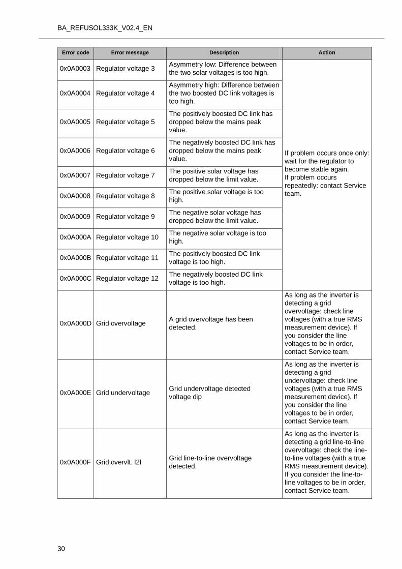
Error code Error message Description Action
0x0A0003 Regulator voltage 3 Asymmetry low: Difference between
the two solar voltages is too high.
If problem occurs once only:
wait for the regulator to
become stable again.
If problem occurs
repeatedly: contact Service
team.
0x0A0004 Regulator voltage 4
Asymmetry high: Difference between
the two boosted DC link voltages is
too high.
0x0A0005 Regulator voltage 5
The positively boosted DC link has
dropped below the mains peak
value.
0x0A0006 Regulator voltage 6
The negatively boosted DC link has
dropped below the mains peak
value.
0x0A0007 Regulator voltage 7 The positive solar voltage has
dropped below the limit value.
0x0A0008 Regulator voltage 8 The positive solar voltage is too
high.
0x0A0009 Regulator voltage 9 The negative solar voltage has
dropped below the limit value.
0x0A000A Regulator voltage 10 The negative solar voltage is too
high.
0x0A000B Regulator voltage 11 The positively boosted DC link
voltage is too high.
0x0A000C Regulator voltage 12 The negatively boosted DC link
voltage is too high.
0x0A000D Grid overvoltage A grid overvoltage has been
detected.
As long as the inverter is
detecting a grid
overvoltage: check line
voltages (with a true RMS
measurement device). If
you consider the line
voltages to be in order,
contact Service team.
0x0A000E Grid undervoltage Grid undervoltage detected
voltage dip
As long as the inverter is
detecting a grid
undervoltage: check line
voltages (with a true RMS
measurement device). If
you consider the line
voltages to be in order,
contact Service team.
0x0A000F Grid overvlt. l2l Grid line-to-line overvoltage
detected.
As long as the inverter is
detecting a grid line-to-line
overvoltage: check the line-
to-line voltages (with a true
RMS measurement device).
If you consider the line-to-
line voltages to be in order,
contact Service team.
BA_REFUSOL333K_V02.5_EN
31
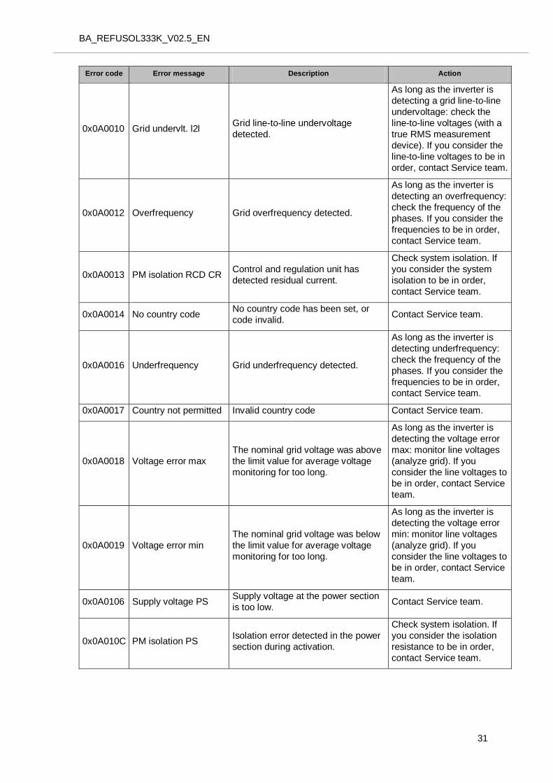
Error code Error message Description Action
0x0A0010 Grid undervlt. l2l Grid line-to-line undervoltage
detected.
As long as the inverter is
detecting a grid line-to-line
undervoltage: check the
line-to-line voltages (with a
true RMS measurement
device). If you consider the
line-to-line voltages to be in
order, contact Service team.
0x0A0012 Overfrequency Grid overfrequency detected.
As long as the inverter is
detecting an overfrequency:
check the frequency of the
phases. If you consider the
frequencies to be in order,
contact Service team.
0x0A0013 PM isolation RCD CR Control and regulation unit has
detected residual current.
Check system isolation. If
you consider the system
isolation to be in order,
contact Service team.
0x0A0014 No country code No country code has been set, or
code invalid. Contact Service team.
0x0A0016 Underfrequency Grid underfrequency detected.
As long as the inverter is
detecting underfrequency:
check the frequency of the
phases. If you consider the
frequencies to be in order,
contact Service team.
0x0A0017 Country not permitted Invalid country code Contact Service team.
0x0A0018 Voltage error max
The nominal grid voltage was above
the limit value for average voltage
monitoring for too long.
As long as the inverter is
detecting the voltage error
max: monitor line voltages
(analyze grid). If you
consider the line voltages to
be in order, contact Service
team.
0x0A0019 Voltage error min
The nominal grid voltage was below
the limit value for average voltage
monitoring for too long.
As long as the inverter is
detecting the voltage error
min: monitor line voltages
(analyze grid). If you
consider the line voltages to
be in order, contact Service
team.
0x0A0106 Supply voltage PS Supply voltage at the power section
is too low. Contact Service team.
0x0A010C PM isolation PS Isolation error detected in the power
section during activation.
Check system isolation. If
you consider the isolation
resistance to be in order,
contact Service team.
BA_REFUSOL333K_V02.4_EN
32
Error code Error message Description Action
0x0A010E Device fault PS Power section hardware shutdown.
Make a note of: When the
error occurred (precisely:
day, kW output, time)
0x0A0110 Solar voltage PS 1 Power section overvoltage shutdown
in positive DC link
Do nothing. The inverter will
acknowledge the error
automatically. If problem
occurs repeatedly, contact
Service team. 0x0A0111 Solar voltage PS 2
Power section overvoltage shutdown
in negative DC link
0x0A0118 Voltage offset PS
Offset adjustment values between
power section and control and
regulation unit divergent.
Contact Service team.
0x0A0119 Current transdcr.PS Current transducer could not detect
any current flow. Do nothing. The inverter will
acknowledge the error
automatically. If problem
occurs repeatedly, contact
Service team.
0x0A011A Activation PS 1 DC discharge is taking too long.
0x0A011B Activation PS 2 DC link voltage drop during
activation.
0x0A011D Activation PS 4 Balancing has failed. Contact Service team.
0x0A011E Activation PS 5 Uploading of DC links has failed.
0x0A011F Parameter error PS 5 Faulty reading or writing process in
power section memory
1.) Switch off device with
DC disconnector.
2.) Wait until the display has
turned off completely.
3.) Switch on device with
DC disconnector.
If this does not rectify the
error, contact Service team.
0A0120 Communication PS
Communication malfunction between
power section and control and
regulation unit.
Do nothing. The inverter will
acknowledge the error
automatically. If problem
occurs repeatedly, contact
Service team.
0x0A0150 Overtemperature 2 Temperature exceeds the configured
limit value.
Check the inverter for heat
build-up or obstruction of
cooling fins. Remove as
necessary. If the error
persists, contact Service
team.
0x0A0151 Overtemperature AC1 Temperature exceeds the configured
limit value.
0x0A0152 Overtemperature AC2 Temperature exceeds the configured
limit value.
0x0A0153 Internal
overtemperature
Temperature exceeds the configured
limit value.
0x0A0154 Overtemperature DC1
Temperature of the cooler on
positive boost converter exceeds the
limit value.
0x0A0155 Overtemperature DC2
Temperature of the cooler on
negative boost converter exceeds
the limit value.
BA_REFUSOL333K_V02.5_EN
33
Error code Error message Description Action
0x0A0156 Overtemperature U Temperature exceeds the configured
limit value.
0x0A0157 Overtemperature V Temperature exceeds the configured
limit value.
0x0A0158 Overtemperature W Temperature exceeds the configured
limit value.
0x0A0159 Fault fan 1 Fault message for fan 1.
0x0A015A Fault fan 2 Fault message for fan 2.
0x0A015B Fault fan 3 Fault message for fan 3.
0x0A015C Fault fan 4 Fault message for fan 4.
0x0A015D Fault fan 5 Fault message for fan 5.
0x0A015E NTC wire break Wire break detected in cooler
sensor. Contact Service team.
0x0A015F NTC short circuit Short circuit detected in cooler
sensor.
0x0A0160 Precharging error Error during precharging.
The DC +/- could be
inverted.
Please check DC wiring. If
you consider the wiring to
be in order, contact
Service team.
0x0A0161 Overcurrent BC Pos.
Hardware shutdown due to
overcurrent in positive boost
converter link
Do nothing. The inverter will
acknowledge the error
automatically. If problem
occurs repeatedly, contact
Service team.
0x0A0162 Overcurrent BC Neg.
Hardware shutdown due to
overcurrent in negative boost
converter link
0x0A0163 Overcurrent Phase U Hardware shutdown due to Phase U
overcurrent
0x0A0164 Overcurrent Phase V Hardware shutdown due to Phase V
overcurrent
0x0A0165 Overcurrent Phase W Hardware shutdown due to Phase W
overcurrent
0x0A0166 Overvoltage DC link
Pos.
Overvoltage detected in positively
boosted DC link
0x0A0167 Overvoltage DC link
Neg.
Overvoltage detected in negatively
boosted DC link
0x0A0168 String error Input current groups connected
incorrectly.
The DC +/- could be
inverted.
Please check DC wiring. If
you consider the wiring to
be in order, contact Service
team.
BA_REFUSOL333K_V02.4_EN
34
Error code Error message Description Action
0x0A0169 Riso wire break
During the function test with a
isolation measuring device, wire
break detected.
Contact Service team.
0x0A0177 Fault fan E1 – E5
The internal speed monitoring has
detected a deviation from the
setpoint speed.
Contact Service team.
0A200D Overtemperature 6 Device temperature too high.
Do nothing. The inverter will
acknowledge the error
automatically. If problem
occurs repeatedly, contact
Service team.
0x0B0001 System 1 Error in error management system.
Contact Service team. 0x0B0002 System 2 Error memory is full.
0x0B0003 System 3 Error acknowledgment failed.
0x0D0001 System error
A connection to the power section
could not be established during the
firmware update.
1.) Switch off device with
DC disconnector.
2.) Wait until the display has
turned off completely.
3.) Switch on device with
DC disconnector.
If this does not rectify the
error, contact Service team.
0x0D0002 PS bootloader Power section bootloader faulty
One of the power section’s
two bootloaders is faulty.
This text is displayed for
information purposes only.
The inverter will continue to
function.
Contact Service team and
arrange firmware update.
0x0D0003 System restart System has been restarted to enable
a firmware update to be performed.
For information purposes
only. If the error occurs but
you have not performed an
update, contact Service
team.
0x100001 Ethernet connection 1 A connection to the Ethernet could
not be established.
Inspect Ethernet
connection:
check IP address, subnet
mask, server address, and
server port.
0x100002 Ethernet connection 2 Loss of Ethernet connection. Check Ethernet connection.
0x100003 Ethernet connection 3 No 100Mbit/s Ethernet connection is
available.
Ethernet connection with
100Mbit/s required. Check
that your network is
transmitting at 100Mbit/s.
BA_REFUSOL333K_V02.5_EN
35
6 6BMaintenance and Cleaning
6.1 44BMaintenance Instructions
To ensure reliable operation of the solar inverter and to safeguard your entitlement to make claims
under the warranty, routine maintenance is required.
Maintenance work must be performed only by trained and qualified personnel authorized by REFUsol.
By way of precaution, we recommend that a servicing and maintenance contract is concluded.
BA_REFUSOL333K_V02.4_EN
36
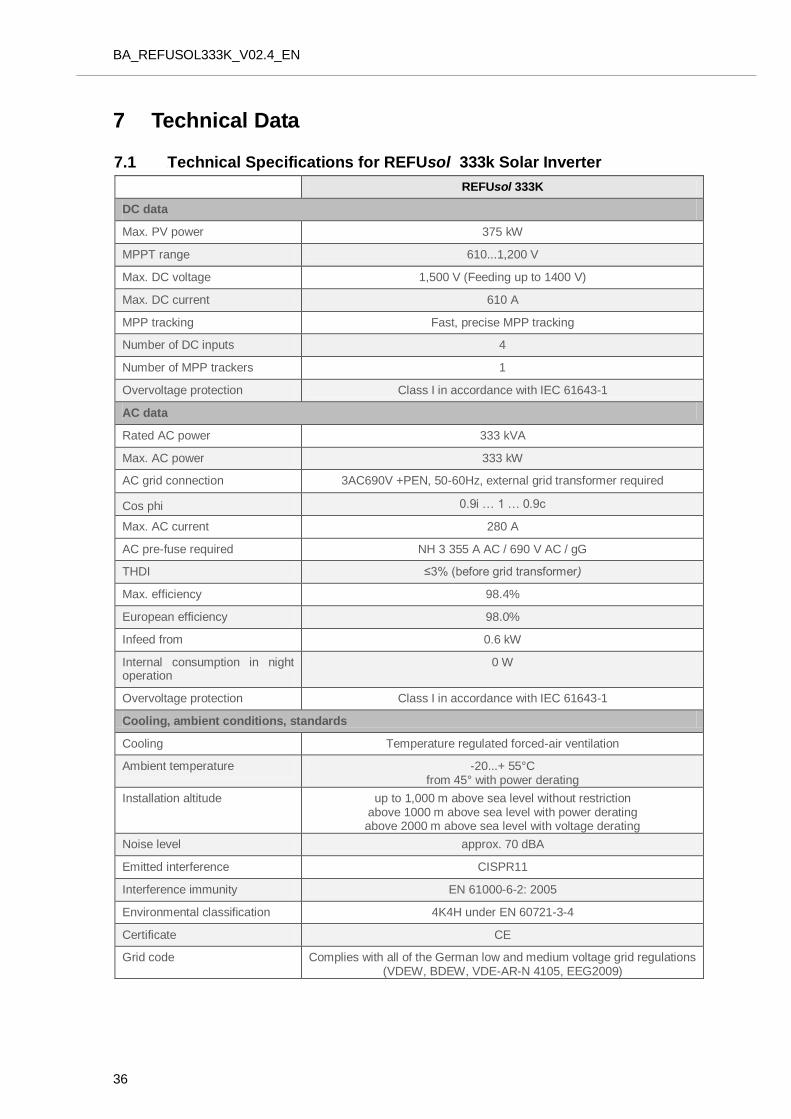
7 7BTechnical Data
7.1 45BTechnical Specifications for REFUsol 333k Solar Inverter
REFUsol 333K
DC data
Max. PV power 375 kW
MPPT range 610...1,200 V
Max. DC voltage 1,500 V (Feeding up to 1400 V)
Max. DC current 610 A
MPP tracking Fast, precise MPP tracking
Number of DC inputs 4
Number of MPP trackers 1
Overvoltage protection Class I in accordance with IEC 61643-1
AC data
Rated AC power 333 kVA
Max. AC power 333 kW
AC grid connection 3AC690V +PEN, 50-60Hz, external grid transformer required
Cos phi 0.9i … 1 … 0.9c
Max. AC current 280 A
AC pre-fuse required NH 3 355 A AC / 690 V AC / gG
THDI ≤3% (before grid transformer)
Max. efficiency 98.4%
European efficiency 98.0%
Infeed from 0.6 kW
Internal consumption in night operation
0 W
Overvoltage protection Class I in accordance with IEC 61643-1
Cooling, ambient conditions, standards
Cooling Temperature regulated forced-air ventilation
Ambient temperature -20...+ 55°C from 45° with power derating
Installation altitude up to 1,000 m above sea level without restriction above 1000 m above sea level with power derating above 2000 m above sea level with voltage derating
Noise level approx. 70 dBA
Emitted interference CISPR11
Interference immunity EN 61000-6-2: 2005
Environmental classification 4K4H under EN 60721-3-4
Certificate CE
Grid code Complies with all of the German low and medium voltage grid regulations (VDEW, BDEW, VDE-AR-N 4105, EEG2009)
BA_REFUSOL333K_V02.5_EN
37
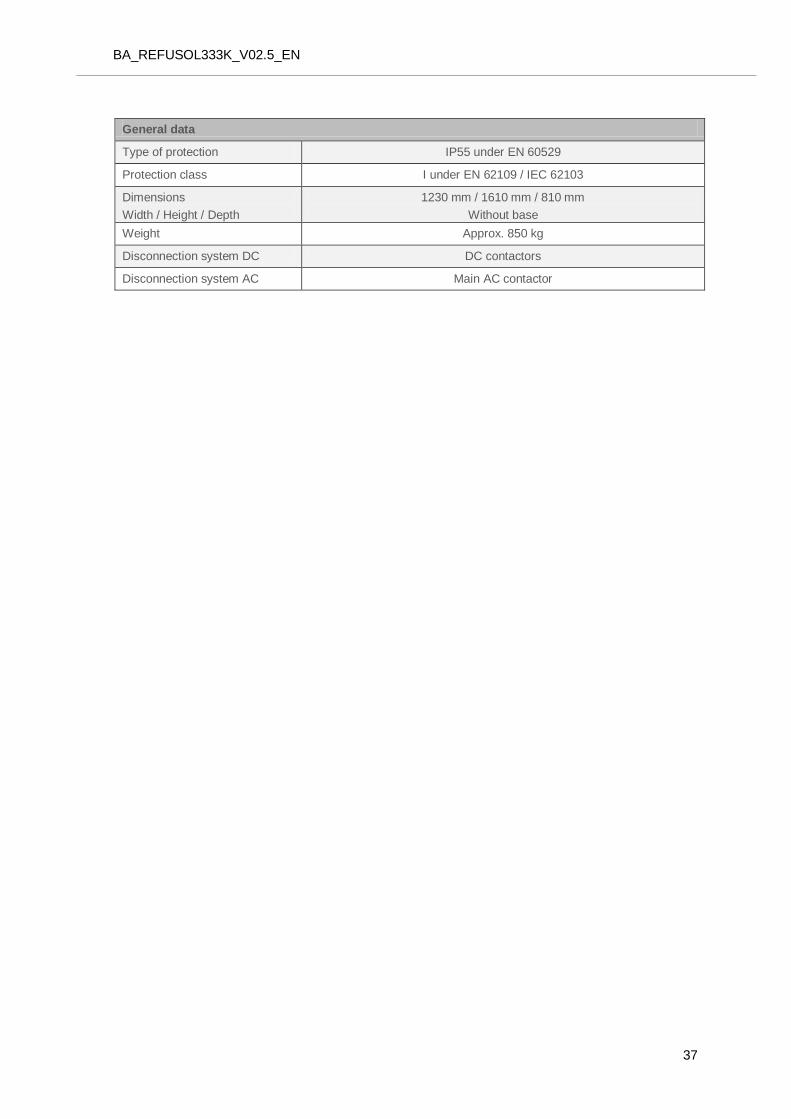
General data
Type of protection IP55 under EN 60529
Protection class I under EN 62109 / IEC 62103
Dimensions
Width / Height / Depth
1230 mm / 1610 mm / 810 mm
Without base
Weight Approx. 850 kg
Disconnection system DC DC contactors
Disconnection system AC Main AC contactor
BA_REFUSOL333K_V02.4_EN
38
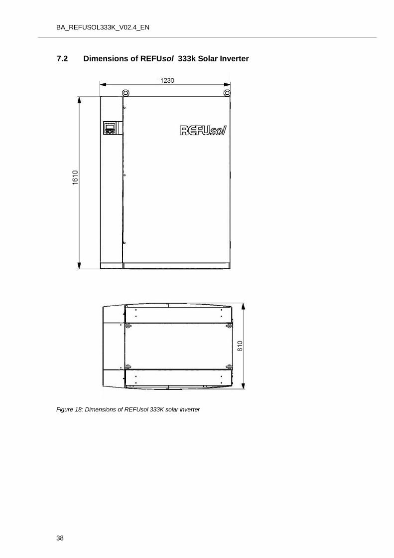
7.2 Dimensions of REFUsol 333k Solar Inverter
Figure 18: Dimensions of REFUsol 333K solar inverter
BA_REFUSOL333K_V02.5_EN
39
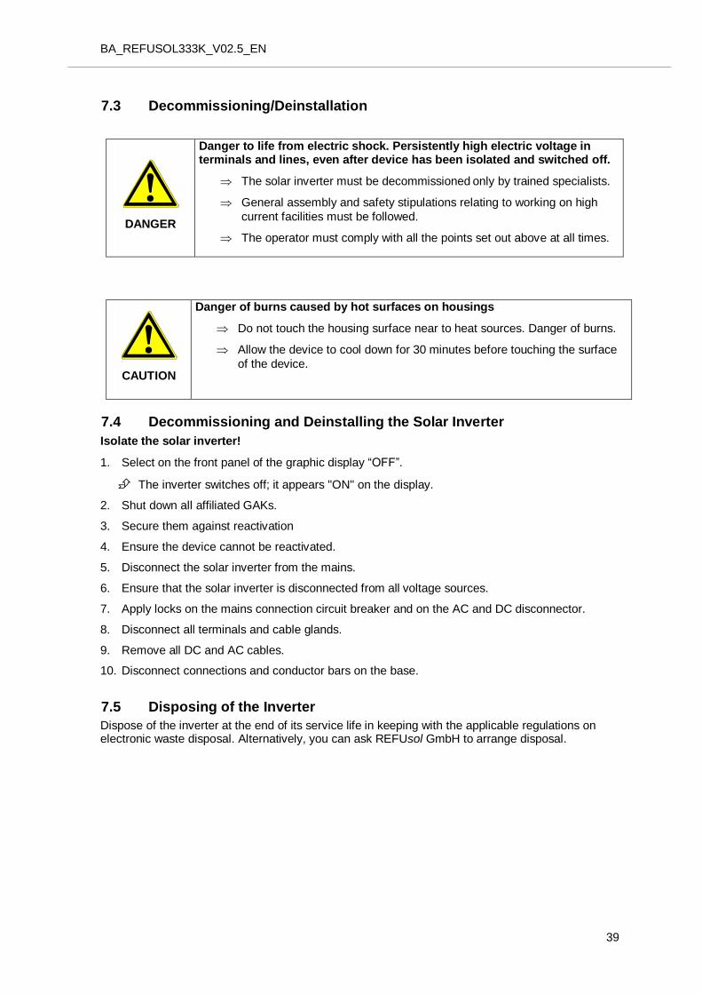
7.3 8BDecommissioning/Deinstallation
DANGER
Danger to life from electric shock. Persistently high electric voltage in terminals and lines, even after device has been isolated and switched off.
The solar inverter must be decommissioned only by trained specialists.
General assembly and safety stipulations relating to working on high
current facilities must be followed.
The operator must comply with all the points set out above at all times.
CAUTION
Danger of burns caused by hot surfaces on housings
Do not touch the housing surface near to heat sources. Danger of burns.
Allow the device to cool down for 30 minutes before touching the surface
of the device.
7.4 48BDecommissioning and Deinstalling the Solar Inverter
Isolate the solar inverter!
1. Select on the front panel of the graphic display “OFF”.
The inverter switches off; it appears "ON" on the display.
2. Shut down all affiliated GAKs.
3. Secure them against reactivation
4. Ensure the device cannot be reactivated.
5. Disconnect the solar inverter from the mains.
6. Ensure that the solar inverter is disconnected from all voltage sources.
7. Apply locks on the mains connection circuit breaker and on the AC and DC disconnector.
8. Disconnect all terminals and cable glands.
9. Remove all DC and AC cables.
10. Disconnect connections and conductor bars on the base.
7.5 49BDisposing of the Inverter
Dispose of the inverter at the end of its service life in keeping with the applicable regulations on electronic waste disposal. Alternatively, you can ask REFUsol GmbH to arrange disposal.
BA_REFUSOL333K_V02.4_EN
40
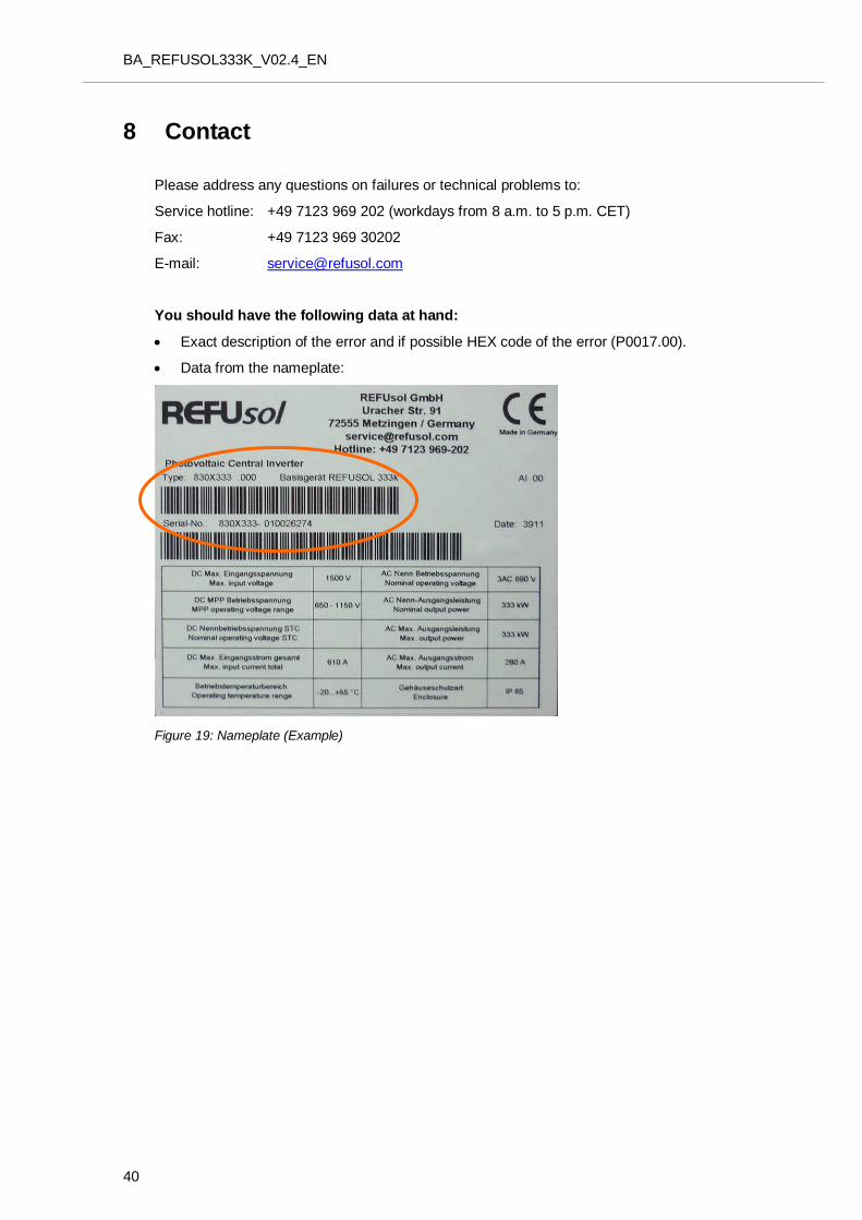
8 9BContact
Please address any questions on failures or technical problems to:
Service hotline: +49 7123 969 202 (workdays from 8 a.m. to 5 p.m. CET)
Fax: +49 7123 969 30202
E-mail: [email protected] H
You should have the following data at hand:
Exact description of the error and if possible HEX code of the error (P0017.00).
Data from the nameplate:
Figure 19: Nameplate (Example)
BA_REFUSOL333K_V02.5_EN
41
9 10BCertificates
The following certificates
EC Declaration of Conformity
Unit Certificate under Medium Voltage Guidelines (BDEW)
can be downloaded from the REFUsol GmbH website www.refusol.com.
BA_REFUSOL333K_V02.4_EN
42
10 11BNote

BA_REFUSOL333K_V02.5_EN
43

All information subject to change. We reserve the right to make technical modifications. Errors excepted.
REFUsol GmbH
Uracherstraße 91
D-72555 Metzingen / Germany
Tel.: +49 7123 969-202
Fax: +49 7123 969-30202
www.refusol.com
Part No.: 0033201