Market Analysis & Literature Review on Refuse Derived Fuel ...

REFUSE DERIVED FUEL (RDF)
by
S. H. Russell
Henningson, Durham & Richardson, Inc. Omaha, Nebraska
Introduction
The term "RDF" is a relatively new member of the advancing mass of resource recovery jargon which is exchanged freely between those involved daily with the problems of recovering energy from solid waste. It is one of those three-letter acronyms that rolls easily off the tongue, but is dangerously ambiguous. Taken literally, "Refuse Derived Fuel" means any fuel derived from refuse including shredded fuel, pyrolysis gas and oil, landfill gas, etc. However, RDF in this paper is defined as that fraction of municipal solid waste composed mainly of cellulose and petroleum derivatives, whether mixed with other non-combustibles in its un-processed form, or in its various processed forms. The purpose of this paper is to discuss the direct combustion of this fraction in a steam generator.
Direct Combustion
Figure 1 shows where the direct combustion technique fits in the context of the rest of resource recovery technology. Two general groups can be defined; Materials Separation and Chemical Conversion. Materials Separation is the physical separation and/or sizing of the various components of solid waste without changing the chemical makeup of any component for the· purpose of preparing them for further physical changes, chemical conversion, or disposal. A few of the many techniques in this general group are shredding, magnetic separation, density separation, screening, nonferrous separation, and various "wet" processes using water as a transport fluid. The second general group of which direct combustion is a part, is Chemical Conversion. This group includes techniques which change the chemical makeup of either processed or un-processed solid waste for the purpose of recovering the heat released in the chemical reaction and/or for changing the solid waste into a more usable form. Pyrolysis and Bioconversion are included as well as direct combustion.
This paper will discuss the two general forms of the direct combustion of RDF (as it has been defined earlier); the use of RDF as a primary fuel, and its use as a supplemental fuel. This paper will also attempt to identify needed areas of research for each of these direct combustion forms.
300

RDF as a Primary Fuel
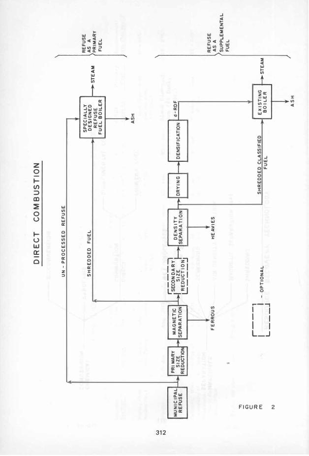
This form of direct combustion uses RDF as the source of greater than fifty percent of the heat input to the steam generator. This requires a steam generator designed specifically for the combustion of refuse when using RDF in its un-processed form. In certain situtations, depending on the type of solid waste processing used to produce the RDF, existing boilers can be modified to burn processed RDF as a primary fuel. In either case, the RDF heat input is usually supplemented by a "conventional" fuel such as gas, oil or coal. Figure 2 shows the typical processing steps required for the different ways of utilizing RDF as a primary fuel; unprocessed fuel firing (mass burn) and processed fuel firing. These are the two types of primary refuse fuel direct combustion now being practiced by certain facilities in this country and in Europe.
Unprocessed RDF Firing (Mass Burn)
There are several operating facilities of this type in the U. S. , Canada and Europe. Table 1 gives the details of most of these facilities. Figure 3 shows the general arrangement of the equipment used in these facilities. The waste is dumped from the collection or transport vehicles into a pit for surge storage, then is moved to a hopper which feeds a traveling/r�rocating grate arrangement on which the refuse is burned. Heat is transferred by radiation and convection in the traditional manner to the boiler walls and hanging tube sections. Some systems separate bulky items such as refridgerators before firing and recover ferrous metal from the ash with magnetic separators.
Processed RDF Firing
In contrast to unprocessed fuel firing, this technique subjects the raw refuse to a· number of different steps of materials separation. before combustion. Most of the systems whether operating or in the final design o f construction phases utilize a new, specially designed RDF boiler with a travel ing grate, spreader stoker design originally used for crushed coal (see Figure 4). The refuse is typically shredded to a 3 to 6 inch (7.62 to 15.24 em) nominal particle size and magnetically separated to recover a ferrous metal fraction before firing ( some systems use air density separation as an additional step). When processed refuse is to be used as a primary fuel in an existing boiler, the raw refuse is typically subjected to additional shredding for smaller particle sizes,and density classified to remove additional noncombustibles. Boilers originally designed to use a solid fuel (coal, bark, etc. ) can then be modified to burn this RDF as the primary fuel.
Table 2 gives the details of many of the systems operating, under design or under construction.
301

>
Comparison and Research Needs
Both the unprocessed RDF firing and processed RDF firing primary fuel systems have been constructed and have operating experience. The question of which form is more desirable is unanswered. A comparison between the two not only points out the advantages and disadvantages of each, but identifies certain areas for needed research.
Steam flow variation.--It has been shown that steam flow variations are less severe in a processed RDF primary fuel system than in an unprocessed RDF system.l Processed fuel has a higher degree of homogeneity than raw refuse creating a more uniform heat release, and a fire which is easier to control. Unprocessed fuel units have fuel firing systems which are modifications of systems originally designed for incineration of raw refuse. Many times, the goals of'refuse incineration conflict with the goals of steam generation from unprocessed refuse. A goal of incineration is not necessarily to create a uniform heat release rate which is important in steam generation. An area for research is to identify how to control steam flow variations in an unprocessed fuel system. Areas for investigation are: boiler control technology, traveling or reciprocating grate design, and auxiliary fuel modulating techniques.
Corrosion.--Refuse derived fuel has been shown to be more corrosive than conventional fuels.2 The small amount of testing which has been completed indicates that greater amounts and rates of chloride corrosion occurs in the fireside of the boiler apparently because of the polyvinalchloride polymer which exists in municipal waste in the form of trash bags, plastic wrap, etc. This problem is perhaps more acute in a system using RDF as primary fuel than in a supplemental fuel system. There is also speculation that this type of corrosion is more severe in a mass burn system than in a processed RDF system.
It is clear that only limited knowledge exists about the actual corrosion mechanism, and the conditions which control it, such as temperature, gas flow rate, excess air rate, boiler geometry, RDF composition, and firing system design. Research directed toward answering boiler corrosion questions could result in the design of more reliable refuse direct combustion systems.
Stack emissions.--Only limited stack emissions testing has been completed for steam generators using "refuse derived fuel as a primary fuel. Considering the number of RDF systems either unde� const�ction or in the design or planning stages, a high priority research need should be the identification of stack emissions from RDF systems.
There is speculation about which of the primary RDF fuel systems has more severe emissions control problem. Since a higher gas flow is needed for complete combustion in a mass burn system, the problem is potentially greater. The East Hamilton SWARU (a processed fuel system)
302

boilers are designed for 37% excess air leaving the boiler as compared to an excess air figure of 84% at the boiler exit in the Nashville mass burn system. Higher air flow per Btu released means more gas to clean up. Research should address the effects on stack emissions of refuse fuel homogeneity, fuel composition, firing system design, boiler geometry, fire control with auxiliary fuel, and air pollution control equipment design and operation.
RDF as a Supplemental Fuel
The major differences between an RDF primary fuel system and a supplemental fuel system are that in the supplemental system, a conventional fuel (gas, oil or coal) supplies over 50% of the heat input and an existing boiler is usually modified for RDF supplemental firing. In certain situations, RDF can be used as a primary fuel in existing boilers (see Table 2), but modification costs are usually prohibitive. The primary attractiveness of the supplemental fuel concept is that when RDF is only used as a fuel supplement, considerable investment capital can be saved because an existing boiler can be modified for use at a relatively small cost. EVen thoug�amore extensive materials separation system is required to prepare an RDF with better fuel properties, the cost of these components is usually more than offset by the savings realized by the elimination of the necessity for a new, specially-designed boiler.
Figure 2, shows that there are two basic types of supplemental RDF systems; the shredded, :classified fuel system and the densified RDF (d-RDF) system.
Shredded, Classified Fuel Supplemental System
The materials separation involved with this type of supplemental fuel system involves size reduction to typically under 1-1/2 inch (3.8lcm) particle size (possibly two stages of shredding or milling) and density classification (usually air density separation). The fuel is then burned either on a traveling grate or in suspension. Table 3 shows the details of the steam generators which now or will fire supplemental shredded RDF. Supplemental rates range from 10% to a possible 50% in these existing steam generators. The only steam generators operating with a shredded RDF supplemental fuel on a day-to-day basis are those operated by the Ames Municipal Electric Service in Ames, Iowa. These three units have been utilizing RDF constantly for about one year at the date of this writing.
Densified Refuse Derived Fuel d-RDF Supplemental System
The advantages of densified or pelletized RDF are: 1) densified RDF will store for longer periods of time than shredded RDF before decomposing and 2) the higher bulk density and shape of the densified fuel pellets
303
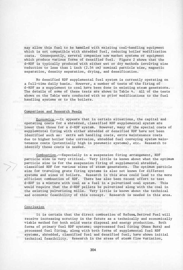
may allow this fuel to be handled with exisitng coal-handling equipment which is not compatible with shredded fuel, reducing boiler modification costs. Consequently, several companies now market systems or equipment which produce various forms of densified fuel. Figure 2 shows that the d-RDF is typically produced with either wet or dry methods involving size reduction to less than I inch (2.54 cm) nominal particle size, magnetic separation, density separation, drying, and densification.
No densified RDF supplemental fuel system is currently operating on a full-time daily basis. However, a number of tests of the firing of d-RDF as a supplement to coal have been done in existing steam generators. The details of some of these tests are shown in Table 4. All of the tests shown on the Table were conducted with no �rior modifications to the fuel handling systems or to the boilers.
Comparison and Research Needs
Economics.--It appears that in certain situations, the capital and operating costs for a shredded, classified RDF supplemental system are lower than those for a d-RDF system. However, many of the special costs of supplemtntal firing with either shredded or densified RDF have not been identified such as: extra ash handling costs, extra maintenance costs due to higher boiler tube corrosion, shredded fuel conveying system maintenance costs (potentially high in pneumatic systems), etc. Research to identify these costs is needed.
Combustion.--Especially in a suspension firing arrangement, RDF particle size is very critical. Very little is known about what the optimum particle size is for the suspension firing of supplemental shredded, classified RDF for various sizes of steam generators. The optimum particle size for traveling grate firing systems is also not known for different systems and sizes of boilers. Research in this area could lead to the more efficient combustion of RDF. There has also been recent effort to test d-RDF in a mixture with coal as a fuel in a pulverized coal system. This would require that the d-RDF pellets be pulverized along with the coal in the existing pulverizing. mills. Very little is known about the technical and economic feasibility of this concept. Research is needed in this area.
Conclusion
It is certain that the direct combustion of Refus�Derived Fuel will receive increasing scrutiny in the future as a technically and economically viable method for both solid waste disposal and energy production. Both forms of primary fuel RDF systems; unprocessed fuel firing (Mass Burn) and processed fuel firing, along with both forms of supplemental fuel RDF systems, shredded, classified fuel and densified fuel, have shown initial technical feasibility. Research in the areas of steam flow Variation,
304
corrosion, stack emissions, �conomics, and combustion efficiency, could serve to reduce-the uncertainty inherent in this new technology.
305

Footnotes
lSommerlad, Robert E. Quality and Characterisitcs of Steam Produced
From Wastes, unpublished paper presented at the Engineering Foundation Conference on Present Status and Research Needs in Energy Recovery from Solid Wastes, September 21, 1976.
�aughan, D. A. Corrosion Mechanisms in Municipal Incinerators Versus Refuse Composition, unpublished paper presented at the Engineering Foundation Conference of Present Status and Research Needs in Energy Recovery from Solid Wastes, September 20 1976.
306

Lo
ca
tio
n
Ch
ica
go
, 1l
1in
01s
Br
ain
tre
e,
Ma
ss
.
Ha
rr
isb
urg
, P
A
w
0
Mo
ntr
ea
l,
-..J
Qu
e
Na
sh
vill
e,
Te
nn
.
No
rfo
lk,
VA
Qu
eb
ec
Cty
, Q
ue
.
Sua
gus
, M
as
s.
TA
13L
£
I
OP
ER
AT
ING
ST
EA
M G
EN
ER
AT
OR
S F
1RIN
C;--U
NP
HO
CE
SSE
D R
EF
US
E
(MASS
BU
RN
)
Ca
pac
ity
S
tar
t-U
p
sh
or
t to
ns
/d
ay
°
Eer
ato
r
Ye
ar
(m
etr
ic t
on
s/
da
:z:y
Cit
y o
f 1
97
2
180
0
Ch
ica
go
( 1
63
3)
To
wn
of
19
71
2
40
Br
ain
tre
e
(21
8)
Cit
y o
f 19
72
7
20
Ha
rr
isb
urg
(6
53
)
Cit
y o
f 1
97
0
12
00
Mo
ntr
ea
l ( 1
08
8)
Na
sh
vil
le
19
74
7
20
Th
er
ma
l (6
53
) T
ra
nsfe
r
Co
rp
.
U.S
. N
avy
1
96
7
36
0
(32
7)
Que
be
c U
rb
an
1
97
4
10
00
Co
nirnu
ri it
l'
(90
7)
RE
SC
O
19
75
1
50
0
( 13
61
)
Bo
ile
r D
es
ign
Dat
a
Ib/
hr
x
10
00
(Kg/
hr
x
10
00
)
4
unit
s,
ea
ch
11
0
(50
)
2 u
nit
s,
ea
ch
30
(13
.6
)
2 u
nit
s,
ea
ch
92
.5
(37
.4
)
4
unit
s,
ea
ch
10
0
(45
.3
)
2
un
its
, e
ac
h 1
35
(61
. 2
)
2
un
its
, e
ac
h 5
0
(22
.7
)
2
unit
s,
ea
ch
81
(36
.-7
)
2 u
nit
s,
ea
ch
18
5
(83
.9
)
ps
ia,
° [
(Kg
/c
m
,oC
)
27
5,
41
4
(19
.3
,2
12
)
25
0,
sa
t.
(17
.5
, s
at.
)
25
0,
45
6
(17
.5
, 2
36
)
22
5,
50
0
(15
.8
,2
60
)
40
0,
60
0
(28
. 1
,3
16
)
27
5,
sa
t.
(19
.3
, s
at)
68
0,
60
0
(47
.8
,3
16
)
89
0,
87
5
(62
.5
, 4
86
)
Aux
illa
ry
F
uel
ga
s
ga
s
oil
oil
ga
s
oil
oil
oil
Bo
ile
r M
an
ufa
ctu
re
r
Wa
lth
er
Gm
bH
R H
ey
Sto
ke
r
Co
rp.
Wa
lth
er
Gm
bH
Do
min
ion
Br
idg
e C
o.
B&
W
Fo
ste
r-
Whe
ele
r C
or
p.
Do
min
ion
Br
idg
e C
o.
Do
min
ion
Bri
dg
e C
o.

w
0
CO
Le-
cAAion
O
pe
ra
tor
NEW'B
ol
le
t:s
:
Akro
n O
hio
C
ity
of
Ak
ro
n
Ea
s�
Ham
ilto
n C
ity
of
Ont· •
. � S
WA
RV
H
amil
ton
Hempfl. t
ead;-
He
mp
ste
ad
N.Y
. R
eso
ur
ces
R
ec
ov
er
y
&is
ting
Bo
iler
:
Ro.ch
este
r,
Ko
da
\{
N..Y
.
TAB
LE
2
STEA
M G
ENE
RA
TO
RS F
IRIN
G P
ROC
ESS
r':D I,
nt"
AS
A P
RJM
A1�Y
FU
EL
Sta
tus
und
er
co
nstr
uct
ion
in o
pe
rat
ion
sin
ce
19
72
und
er
Re
fus
e C
ap
acit
y,
sh
or
t to
ns
/d
ay
(M
etr
ic t
on
s/
da
y)
10
00
(90
7)
60
0
(544
)
20
00
co
nstr
uct
ion
( 18
14
)
ope
ra
tin
g 1
80
(16
3)
Bo
ile
r D
es
i gn
Da
ta
1b/h
r x
10
00
'
(kg
/hr
x 1
00
0)
3 u
nits
, ea
ch 1
26
(57
)
2
unit
s,
ea
ch 1
06
(48
. 1
)
40
0
( 18
1)
77
(34
.9
)
u
p;;ia
, fO
(K
g/c
m,2
C
)
56
0,
47
9
25
0,
sa
t.
(17
.5
, s
at)
Su
ppl
em
en
tal
Fue
l
#2
oil
oil
oil
.
#6
oil
Co
rnrne
nts
den
sit
y s
ep
arat
io:-:
inc
lud
ed
in
fue
l pr
oc
es
s in
g
No
ste
arn
ma
rk
et
Ste
am
so
ld t
o L
on
! Is
lan
d L
ight
ing
C"
for
ele
ctr
icit
y p
ro
duc
tio
n.
Als
o b
\.!rns
dr
ied
wa
ste
wa
ter
slU:
dge
Ko
da
k u
se
s s
tea
�
inte
rn
a ll
y.

w
o
CO
TA
BL
E
ST
EA
M G
EN
ER
AT
OR
S F
IRIN
G :;
HR
ED
Dt�
D,
CA
LSS
lFIE
D S
UP
PL
EM
EN
TA
L R
DF
Lo
cati
on
, F
ac
ilit
y
Am
es
, Io
wa
U
nit
s 5
, 6
,
&7
Op
er
ato
r
Am
es
Mu
nic
ipa
l E
lect
ric
Se
rv
ice
Er
idg
ep
or
t,
Un
it"
d
Co
nn.,
B
rid
ge
-Il
lum
ina
tin
g
po
rt
Ha
rb
or
S
tati
on
Un
its
HI a
nd #
2
Un
ite
d
St.
L
ou
is,
MO
U
nio
n E
lect
ric
M
eram
ec P
lan
t
Wis
con
sin
Oa
k
WE
PC
O
Cr
ee
k P
ow
er
S
tati
on
Bo
ile
r D
es
ign
Da
ta
lb/h
r x
1
00
0
ps-ia
, 0 F
R
DF
Pr
odu
ced
B
y:
2
0 (K
g/hr
x
100
0)
(Kg/
en:',
C)
Cit
y o
f A
me
s S
oli
d W
ast
e
Re
cove
ry
Sy
st.
Re
sour
ce
Re
cov
er
y
Ass
oci
ate
s
St.
L
ou
is D
em
on
s
tra
tio
n P
lan
t
Am
er
ico
log
y,
Mil
wa
uke
e R
eso
ur
ce
Re
cove
ry
Pla
nt
#7
36
0
( 16
3)
#6
12
5
(57
)
#5
9
5
(43
)
90
0,
90
0
(63
,4
82
)
72
5,
82
5
(51
,4
41
)
71
0,
82
5
(50
, 4
41
)
2 u
nit
s,
ea
ch 9
25 -
-
(42
0)
Fir
ing
Sy
ste
m
Ta
nge
nti
al
tra
vell
ing
g
ra
te
tra
vell
ing
g
ra
te
cy
clo
ne
.b
ur
ne
rs
tan
gen
tia
l s
ys
pe
ns
io
n
sus
pe
nsi
on
Sup
ple
me
nta
l R
ate
8%
-
10%
10
%
-5
0%
10%
-
50
%
30
%
-4
0%
9%
-
27
%
100/
.
Pr
ima
ry
F
uel
S"ta
tus
coa
l, g
as
op
er
atin
g r
egu
la rl
y w
ith
coa
l,
ga
s R
DF
sin
ce
No
v •
.
197
5
coa
l,
ga�
coa
l,
oil
R
DF
pla
"t
un
de
r de
sig
n
coa
l,
ga.
s
de
mo
ns
tra
tio
:1.
coa
l
pla
nt
:10
lo
n,;
:.:: �
op
er
a r
ing
re
gu
la d
y
RD
F p
lant
un
der
co
nst
r:;.
H
an

tv
a
TA
BL
E 4
ST
EA
M
GE
NE
RA
TO
RS
TE
ST
ED
W
ITI!
TH
E S
UP
PL
F:M
F.N
TA
L
FIR
IN
G O
F
d-R:
DF
Lo
cati
on
F
ac
ilit
y
Piq
ua,
Oh
io
Boi
ler
No
.4
Wri
ght
Pa
tte
,so
n
AF
B
Boi
ler
Pla
nt
Oo
e,
at
ion
Piq
ua E
lect
ric
U
tili
ties
Pow
er
P
lan
t
U.S
. A
ir
Fo
rce
Osh
ko
sh,
Wis
e.
Un
ive
rsit
y o
f U
niv
er
sit
y o
f W
isco
ns
in
Wis
co
nsi
n,
Osh
ko
sh C
am
pus
B
oil
er
Pla
nt
Da
te a
nd
Du
rat
ion
of
Te
st
Ju
ne
27,
19
75
7 h
our
s
Au
g.
197
5 3
0 h
our
s
Aug
. 1
97
6
8 h
our
s
"Te
ste
d i
or a
bo
ut o
ne
ho
ur
at 1
00
0/. d
-RD
F
Bo
ile
r D
es
ign
Da
ta
Fir
ing
lb/h
r x
10
00
p
sia
, \IF
B
oile
r M
etho
d
(Kg
/hr
x 1
000)
(K
g/c
m2,
DC
) M
fg.
Ch
ain
1
50
4
54,
750
C
E
Gr
ate
(6
8)
(31
.9,3
99
) S
tok
er
Tr
ave
llin
g
2 u
nit
s,
ea
ch
12
5, s
at.
E
dg
e M
oor
G
ra
te
80
(3
6.3
) (8
.8 s
at
. )
Iron
Wo
rks
S
pr
ea
de
r
Sto
ker
Vib
ra
tin
g 50
lI
S, s
at.
W
i.ck
es
�ra
te
(22
.7)
(8.
I,
sat.
)
d-R
DF
P
rim
ar
y
Sup
ple
men
t,,1
ma
de
by
Fu
el
Ra
te (
Btu
bas
is)
Bla
ck C
law
-c
oa
l 2
0 -
24
0/.
so
n (
#2 f
uel,
3
/8"
dia
. )
Bl
ac
k C
la
w1:
oal
so
n
({12
f
ue
l,
23
-2
7%
3/
8"
di
a.
)
Gr
uma
n co
al
20 -
24'r.
" (5
/8"
dia
.. )

..,
G)
c
:u
rT\ w
RES
OUR
CE
REC
OV
ERY
TEC
HNO
LOG
Y
,.---S
HR
ED
DI
NG
,..-- M
AG
NE
TI
C
SE
PA
RA
TIO
N
(Fe
)
MA
TE
RIA
LS
S
EP
AR
AT
ION
�
AIR
D
EN
SI
TY
S
EP
AR
AT
ION
--- S
CR
EE
NIN
G
"'--- N
ON
-F
e
SE
PA
RA
TIO
N
'-- W
ET
P
RO
CE
SS
ES
DIR
EC
T
CO
MB
US
TIO
N
CH
EM
ICA
L
CO
NV
ER
SIO
N
( P
YR
OL
YS
IS
� B
IOC
ON
VE
RS
ION
PR
IMA
RY
F
UE
L
SU
PP
LIM
EN
TA
L
FU
EL
W
r-J
DIR
EC
T
CO
M B
US
TIO
N
UN
-P
RO
CE
SS
ED
R
EF
US
E
SP
EC
IA
LL
Y
SH
RE
DD
ED
F
UE
L
DE
SI
GN
ED
�
ST
EA
M
RE
FU
SE
FU
EL
B
OIL
ER
AS
H
� PRI
MA
RY
r;
�O-;:;-D
�71
M
UN
IC
IPA
L
SI
ZE
S
IZ
E
I �I
DE
NS
IT
Y
, -
'DR
YI
NG
' -'D
EN
SIF
ICA
TIO
NI d
-R
DF
RE
FU
SE
R
ED
UC
TIO
I R
ED
UC
TI
ON
�S
EP
AR
AT
IO
N�
�
."
CO)
C
:0
ITI
N
L-_
__
:J
FE
RR
OU
S
r-
--
' I
I -
OP
TIO
NA
L
L _
__
J
1, H
EA
VI
ES
SH
RE
DD
ED
C
LA
SS
IFIE
D
FU
EL
EX
IS
TI
NG
BO
IL
ER
AS
H
ST
EA
M
RE
FU
SE
AS
A
PR
IM
AR
Y
FU
EL
RE
FU
SE
AS
A
SU
PP
L.E
ME
NT
A L
Fu
EL

w
.....
w ."
Cl
C
::u
rrI
�
iA
�CR
ANE
FRAG
MEN
TIZE.R
MOV
ING
GRA
TE S
YST
EM
SO
UR
CE
:W
HE
EL
AB
OR
ATO
R-
FR
YE
PR
OF
ILE
O
F
TO
S\TACK
WH
EE
LA
BO
RA
TO
R -
FR
YE
B
OIL
ER
P
LA
NT
S
AU
GU
S,
MA
SS
.

w
.....
�
"Tl
G)
C
::0
m
�
1.0.
FAN
BANK
EL
ECTR
OSTA
TIC
PREC
IPITA
TOR
AIR
�TE
R-WA
LLEO
FU
RNAC
E
TYP
ICA
L P
RO
CES
SE
D R
DF
PR
IMA
RY
FUE
L S
TE
AM
GE
NER
AT
OR