REFRIGERATION AND AIR CONDITIONINGairwalkbooks.com/images/pdf/pdf_93_1.pdfREFRIGERATION & AIR...
107
(Near All India Radio) 80, Karneeshwarar Koil Street, Mylapore, Chennai – 600 004. Ph.: 2466 1909, 94440 81904 Email: [email protected], [email protected] www.airwalkbooks.com, www.srbooks.org REFRIGERATION AND AIR CONDITIONING Dr. S. Ramachandran, M.E., Ph.D., Dr. A. Anderson, M.E., Ph.D., Professors - Mech Sathyabama Institute of Science and Technology Chennai - 119 For B.E/B.Tech Engineering Students As Per Revised Syllabus of Leading Universities in India Including Dr. APJ Abdul Kalam Technological University, Kerala
Transcript of REFRIGERATION AND AIR CONDITIONINGairwalkbooks.com/images/pdf/pdf_93_1.pdfREFRIGERATION & AIR...
(Near All India Radio)
80, Karneeshwarar Koil Street,
Mylapore, Chennai – 600 004.
Ph.: 2466 1909, 94440 81904Email: [email protected],
www.airwalkbooks.com, www.srbooks.org
REFRIGERATION AND
AIR CONDITIONING
Dr. S. Ramachandran, M.E., Ph.D.,
Dr. A. Anderson, M.E., Ph.D.,
Professors - Mech
Sathyabama Institute of Science and Technology
Chennai - 119
For B.E/B.Tech Engineering Students
As Per Revised Syllabus of Leading Universities in India
Including Dr. APJ Abdul Kalam Technological University, Kerala
ISBN:978-93-88084-07-9
First Edition : 08-07-2018
225/-
978-93-88084-07-9
www.srbooks.orgwww.airwalkbooks.com
Cell: 9600003081, 9600003082
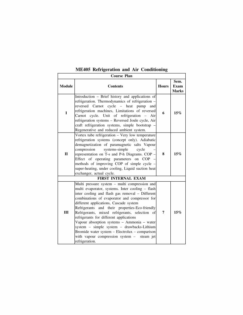
ME405 Refrigeration and Air ConditioningCourse Plan
Module Contents HoursSem.ExamMarks
I
Introduction – Brief history and applications ofrefrigeration. Thermodynamics of refrigeration –reversed Carnot cycle – heat pump andrefrigeration machines, Limitations of reversedCarnot cycle. Unit of refrigeration – Airrefrigeration systems – Reversed Joule cycle, Aircraft refrigeration systems, simple bootstrap –Regenerative and reduced ambient system.
6 15%
II
Vortex tube refrigeration – Very low temperaturerefrigeration systems (concept only). Adiabaticdemagnetization of paramagnetic salts Vapourcompression systems-simple cycle –representation on T-s and P-h Diagrams. COP –Effect of operating parameters on COP –methods of improving COP of simple cycle –super-heating, under cooling, Liquid suction heatexchanger, actual cycle.
8 15%
FIRST INTERNAL EXAM
III
Multi pressure system – multi compression andmulti evaporator, systems. Inter cooling – flashinter cooling and flash gas removal – Differentcombinations of evaporator and compressor fordifferent applications, Cascade systemRefrigerants and their properties-Eco-friendlyRefrigerants, mixed refrigerants, selection ofrefrigerants for different applicationsVapour absorption systems – Ammonia – watersystem – simple system – drawbacks-LithiumBromide water system – Electrolux – comparisonwith vapour compression system – steam jetrefrigeration.
7 15%

IV
Application of refrigeration – domestic refrigerators– water coolers – ice plants. Cold storages – foodpreservation methods – plate freezing, quick-freezing.Refrigeration system components – Compressors,condensers, expansion devices, evaporators. Coolingtowers – Different types and their application fields– Refrigerant leakage and detection – charging ofrefrigerant – system controls.
6 15%
SECOND INTERNAL EXAM
V
Air conditioning – meaning and utility, comfort andindustrial air conditioning. Psychometric properties –saturated and unsaturated air, dry, wet and dew pointtemperature – humidity, specific humidity, absolutehumidity, relative humidity and degree of saturation– thermodynamic equations – enthalpy of moisture– adiabatic saturation process – psychrometers.Thermodynamic wet bulb temperature, psychometricchart – Psychometric processes – adiabatic mixing –sensible heating and cooling – humidifying anddehumidifying, air washer – bypass factor – sensibleheat factor-RSHF and GSHF line – Design condition– Apparent dew point temperature – Choice ofsupply condition, state and mass rate of dehumidifedair quantity – Fresh air supplied – air refrigeration.Comfort air conditioning – factors affecting humancomfort. Effective temperature – comfort chart.Summer air conditioning – factors affecting – coolingload estimation.
8 20%
VI
Air conditioning system – room air conditioner –split system-packaged system-all air system-chilledwater system. Winter air conditioning – factorsaffecting heating system, humidifiers. Year roundair conditioning AC system controls-thermostat andhumidistat. Air distribution systems – duct systemand design – Air conditioning of restaurants,hospitals, retail outlets, computer center, cinematheatre, and other place of amusement. Industrialapplications of air conditioning.
7 20%
END SEMESTER EXAM
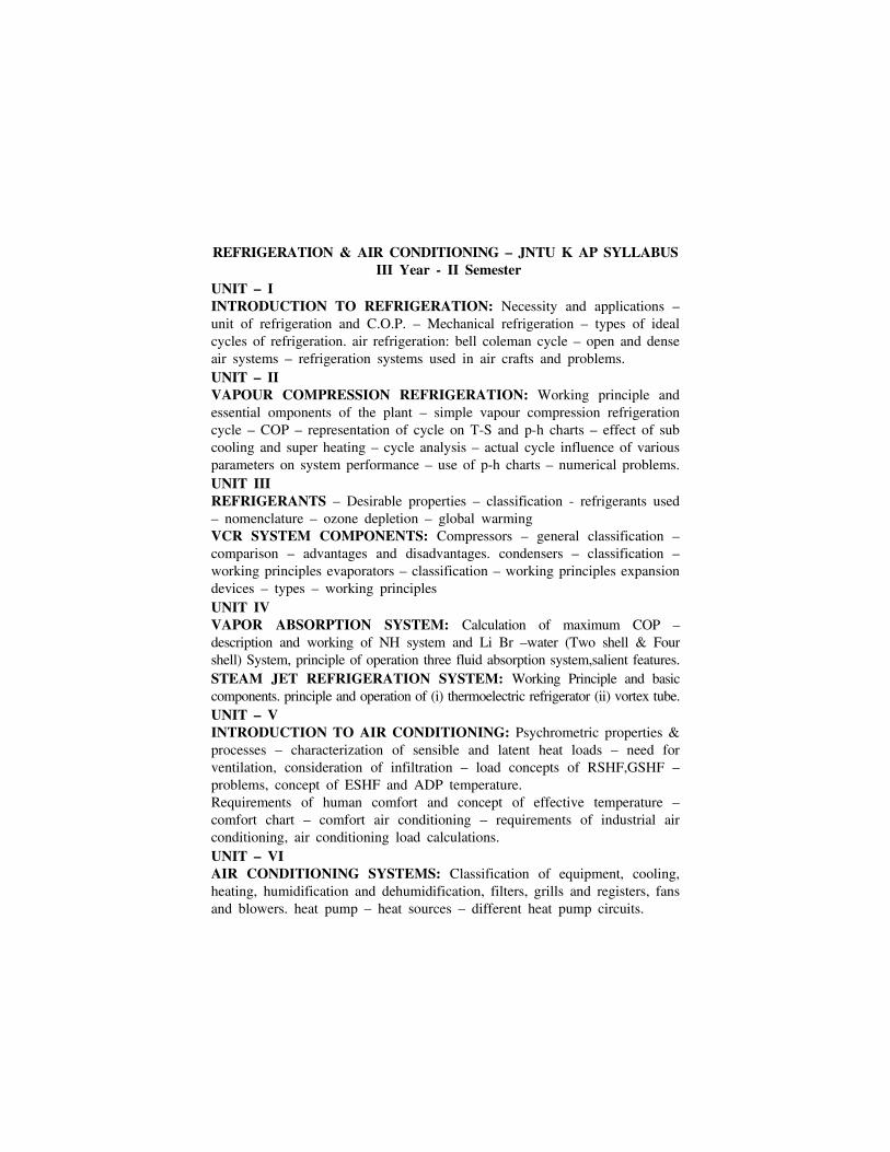
REFRIGERATION & AIR CONDITIONING – JNTU K AP SYLLABUS III Year - II Semester
UNIT – IINTRODUCTION TO REFRIGERATION: Necessity and applications –unit of refrigeration and C.O.P. – Mechanical refrigeration – types of idealcycles of refrigeration. air refrigeration: bell coleman cycle – open and denseair systems – refrigeration systems used in air crafts and problems. UNIT – IIVAPOUR COMPRESSION REFRIGERATION: Working principle andessential omponents of the plant – simple vapour compression refrigerationcycle – COP – representation of cycle on T-S and p-h charts – effect of subcooling and super heating – cycle analysis – actual cycle influence of variousparameters on system performance – use of p-h charts – numerical problems.UNIT IIIREFRIGERANTS – Desirable properties – classification - refrigerants used– nomenclature – ozone depletion – global warmingVCR SYSTEM COMPONENTS: Compressors – general classification –comparison – advantages and disadvantages. condensers – classification –working principles evaporators – classification – working principles expansiondevices – types – working principles UNIT IVVAPOR ABSORPTION SYSTEM: Calculation of maximum COP –description and working of NH system and Li Br –water (Two shell & Fourshell) System, principle of operation three fluid absorption system,salient features.STEAM JET REFRIGERATION SYSTEM: Working Principle and basiccomponents. principle and operation of (i) thermoelectric refrigerator (ii) vortex tube.UNIT – VINTRODUCTION TO AIR CONDITIONING: Psychrometric properties &processes – characterization of sensible and latent heat loads – need forventilation, consideration of infiltration – load concepts of RSHF,GSHF –problems, concept of ESHF and ADP temperature.Requirements of human comfort and concept of effective temperature –comfort chart – comfort air conditioning – requirements of industrial airconditioning, air conditioning load calculations.UNIT – VI AIR CONDITIONING SYSTEMS: Classification of equipment, cooling,heating, humidification and dehumidification, filters, grills and registers, fansand blowers. heat pump – heat sources – different heat pump circuits.

Table of Contents
Module I Reversed Carnot Cycle and Air Refrigeration 1
1.1 Introduction . . . . . . . . . . . . . . . . . . . . . . . . . . . . . . . . . . . . . . . 1.1
1.1.1 Fundamentals of Refrigeration. . . . . . . . . . . . . . . . . . 1.1
1.1.1.1 Briefly history . . . . . . . . . . . . . . . . . . . . . . . . . . . . . . . 1.1
1.1.2 Applications of Refrigeration . . . . . . . . . . . . . . . . . . . 1.2
1.1.3 Important elements of a refrigeration system . . . . . 1.2
1.1.4 Types of Mechanical Refrigeration system . . . . . . . . 1.3
1.1.5 Unit of Refrigeration: (Ton of Refrigeration) . . . . . . 1.3
1.2 Air Refrigeration System . . . . . . . . . . . . . . . . . . . . . . . . . . . . 1.6
1.2.1 Air Refrigeration Cycles . . . . . . . . . . . . . . . . . . . . . . . 1.7
1.3 Reversed Carnot Cycle . . . . . . . . . . . . . . . . . . . . . . . . . . . . . 1.7
1.3.1 Heat pump and refrigeration machines . . . . . . . . . . 1.9
1.3.1.1 Merits of Reversed Carnot Cycle . . . . . . . . . . . . . . 1.18
1.3.1.2 Demerits of Reversed Carnot Cycle (Limitations) 1.18
1.4 Bell-Coleman Cycle (Reversed Joule Cycle). . . . . . . . . . . . 1.18
1.5 Aircraft Refrigeration System . . . . . . . . . . . . . . . . . . . 1.53
1.6 Simple Bootstrap Type . . . . . . . . . . . . . . . . . . . . . . . . . . . . . 1.71
1.7 Regenerative System . . . . . . . . . . . . . . . . . . . . . . . . . . . . . . . 1.78
1.8 Reduced Ambient System. . . . . . . . . . . . . . . . . . . . . . . . . . . 1.84
Module II Vortex tube, Low temperature andVapour Compression Refrigeration (VCR) Systems
2.1 Vortex Tube Refrigeration . . . . . . . . . . . . . . . . . . . . . . . . . . . 2.1
2.2 Very Low Temperature Refrigeration Systems . . . . . . . . . . 2.4
2.2.1 Cascade refrigeration system . . . . . . . . . . . . . . . . . . . 2.4
2.2.2 Solid Carbondioxide or dry ice . . . . . . . . . . . . . . . . . 2.7
2.2.3 Liquefaction of Gases. . . . . . . . . . . . . . . . . . . . . . . . . 2.12
Contents C.1
2.2.3.1 Linde system and Claude system/Air LiquefactionSystem Hampson-Linde (Gas) Air Liquefaction System . 2.12
2.2.3.2 Claude System for Liquefying air . . . . . . . . . . . . . 2.13
2.3 Adiabatic Demagnetization of Paramagnetic Salts. . . . . . 2.14
2.4 Vapour Compression Refrigeration . . . . . . . . . . . . . . . . . . . 2.16
2.5 PH Chart . . . . . . . . . . . . . . . . . . . . . . . . . . . . . . . . . . . . . . . . 2.41
Module III
3.1 Multi-pressure Systems. . . . . . . . . . . . . . . . . . . . . . . . . . . . . . 3.1
3.2 Flash Gas Removal . . . . . . . . . . . . . . . . . . . . . . . . . . . . . . . . . 3.3
3.3 Intercooling . . . . . . . . . . . . . . . . . . . . . . . . . . . . . . . . . . . . . . . . 3.4
3.3.1 Flash Intercooling . . . . . . . . . . . . . . . . . . . . . . . . . . . . 3.4
3.3.2 Water intercooling . . . . . . . . . . . . . . . . . . . . . . . . . . . . 3.6
3.3.3 Intermediate Pressure . . . . . . . . . . . . . . . . . . . . . . . . . 3.6
3.4 Multi Compression System . . . . . . . . . . . . . . . . . . . . . . . . . . 3.7
3.5 Different Combinations of Evaporator and Compressor forDifferent Applications . . . . . . . . . . . . . . . . . . . . . . . . . . . . . . . . . 3.30
3.6 Cascade Refrigeration System . . . . . . . . . . . . . . . . . . . . . . . 3.38
3.7 Refrigerants And Their Properties . . . . . . . . . . . . . . . . . . . 3.41
3.7.1 Classification of refrigerants. . . . . . . . . . . . . . . . . . . 3.41
3.7.2 Various Refrigerants and their properties . . . . . . . 3.43
3.7.3 Characteristics of good refrigerants . . . . . . . . . . . . . 3.46
3.7.4 Refrigerants Number . . . . . . . . . . . . . . . . . . . . . . . . . 3.47
3.7.5 Desirable Properties for refrigerant selection . . . . . 3.50
3.7.6 Ozone Layer Depletion. . . . . . . . . . . . . . . . . . . . . . . . 3.52
3.7.7 Global Warming . . . . . . . . . . . . . . . . . . . . . . . . . . . . . 3.53
3.7.8 Ozone Depleting Potential (ODP) and Global WarmingPotential (GWP) of Various Refrigerants . . . . . . . . . . . . . 3.53
C.2 Refrigeration and Air Conditioning - www.airwalkbooks.com

3.8 Eco-Friendly Refrigerants . . . . . . . . . . . . . . . . . . . . . . . . . . . 3.54
3.9 Classification of Refrigerants Based on Number of ChemicalCompounds . . . . . . . . . . . . . . . . . . . . . . . . . . . . . . . . . . . . . . . . . . 3.56
3.10 Selection of Refrigerants for Different Applications. . . . 3.60
3.11 Vapour Absorption System. . . . . . . . . . . . . . . . . . . . . . . . . 3.66
3.12 Ammonia - Water Absorption System . . . . . . . . . . . . . . . 3.72
3.13 Lithium Bromide Water Vapour Absorption System . . . 3.74
3.14 Comparision Between Vapour Compression and VapourAbsorption System . . . . . . . . . . . . . . . . . . . . . . . . . . . . . . . . . . . . 3.77
3.15 Application of Cryogenic. . . . . . . . . . . . . . . . . . . . . . . . . . . 3.80
3.16 Electrolux Vapour Absorption System . . . . . . . . . . . . . . . 3.81
3.17 Steam Jet Refrigeration System (Ejector RefrigerationSystem) . . . . . . . . . . . . . . . . . . . . . . . . . . . . . . . . . . . . . . . . . . . . . 3.84
3.18 Thermo-electric Refrigeration (TER) System . . . . . . . . . . 3.92
Module IV: Application of Refrigeration andRefrigeration System Components
4.1 Application of Refrigeration . . . . . . . . . . . . . . . . . . . . . . . . . . 4.1
4.1.1 Food processing, preservation . . . . . . . . . . . . . . . . . . . 4.1
4.1.2 Chemical and process industries . . . . . . . . . . . . . . . . 4.3
4.1.3 Special applications . . . . . . . . . . . . . . . . . . . . . . . . . . . 4.5
4.2 Domestic Refrigerators . . . . . . . . . . . . . . . . . . . . . . . . . . . . . . 4.7
4.2.1 Parts of the household refrigerator:. . . . . . . . . . . . . . 4.9
4.3 Water Coolers. . . . . . . . . . . . . . . . . . . . . . . . . . . . . . . . . . . . . 4.12
4.4 Ice Plants . . . . . . . . . . . . . . . . . . . . . . . . . . . . . . . . . . . . . . . . 4.16
4.5 Cold Storage . . . . . . . . . . . . . . . . . . . . . . . . . . . . . . . . . . . . . . 4.18
4.6 Food Preservation Methods . . . . . . . . . . . . . . . . . . . . . . . . . 4.19
4.7 Contact or Plate Freezing . . . . . . . . . . . . . . . . . . . . . . . . . . 4.22
4.8 Quick Freezing. . . . . . . . . . . . . . . . . . . . . . . . . . . . . . . . . . . . 4.23
Contents C.3
4.9 Refrigeration System. . . . . . . . . . . . . . . . . . . . . . . . . . . . . . . 4.25
4.10 Compressor . . . . . . . . . . . . . . . . . . . . . . . . . . . . . . . . . . . . . . 4.25
4.11 Condensers . . . . . . . . . . . . . . . . . . . . . . . . . . . . . . . . . . . . . . 4.28
4.11.1 Parallel-flow condenser . . . . . . . . . . . . . . . . . . . . . . 4.29
4.11.2 Counter flow-Shell and tube condensor . . . . . . . . 4.30
4.11.3 Cross flow - Shell and tube condenser. . . . . . . . . 4.31
4.11.4 Evaporative surface condenser . . . . . . . . . . . . . . . . 4.31
4.12 Expansion Devices . . . . . . . . . . . . . . . . . . . . . . . . . . . . . . . . 4.32
4.13 Evaporator . . . . . . . . . . . . . . . . . . . . . . . . . . . . . . . . . . . . . . 4.34
4.13.1 Bare tube coil evaporator . . . . . . . . . . . . . . . . . . . . 4.34
4.13.2 Finned evaporator . . . . . . . . . . . . . . . . . . . . . . . . . . 4.35
4.13.3 Shell and tube evaporator . . . . . . . . . . . . . . . . . . . 4.36
4.14 Cooling Towers. . . . . . . . . . . . . . . . . . . . . . . . . . . . . . . . . . . 4.37
4.14.1 Capacity of cooling tower . . . . . . . . . . . . . . . . . . . . 4.37
4.14.2 Natural draft cooling towers . . . . . . . . . . . . . . . . . 4.37
4.14.3 Mechanical draft cooling towers . . . . . . . . . . . . . . 4.40
4.15 Refrigerant Leakage and Detection . . . . . . . . . . . . . . . . . 4.42
4.15.1 Ammonia refrigerant leakage and detection: . . . . 4.42
4.15.2 Freon-12 leakage and detection . . . . . . . . . . . . . . . 4.43
4.16 Charging of Refrigerant . . . . . . . . . . . . . . . . . . . . . . . . . . . 4.44
4.16.1 Methods of charging refrigerant. . . . . . . . . . . . . . . 4.44
4.16.1.1 Charging through suction valve . . . . . . . . . . . . . . 4.44
4.16.1.2 Charging through discharge valve . . . . . . . . . . . . 4.45
4.16.1.3 Charging through charging valve. . . . . . . . . . . . . 4.47
4.17 System Control. . . . . . . . . . . . . . . . . . . . . . . . . . . . . . . . . . . 4.48
4.17.1 Starting relay . . . . . . . . . . . . . . . . . . . . . . . . . . . . . . 4.49
4.17.2 Overload protector . . . . . . . . . . . . . . . . . . . . . . . . . . 4.49
C.4 Refrigeration and Air Conditioning - www.airwalkbooks.com
4.17.3 Thermostat . . . . . . . . . . . . . . . . . . . . . . . . . . . . . . . . 4.49
Module V Psychrometric Processes and Airconditioning
5.1 Air Conditioning . . . . . . . . . . . . . . . . . . . . . . . . . . . . . . . . . . . 5.1
5.2 Psychrometry . . . . . . . . . . . . . . . . . . . . . . . . . . . . . . . . . . . . . 5.3
5.3 Psychrometric Parameters . . . . . . . . . . . . . . . . . . . . . . . . . . 5.4
5.4 Psychrometric Properties . . . . . . . . . . . . . . . . . . . . . . . . . . . . 5.5
5.5 Property Calculations of Air Vapour Mixtures . . . . . . . . . . 5.9
5.6 Psychrometric Charts . . . . . . . . . . . . . . . . . . . . . . . . . . . . . . 5.23
5.7 Psychrometric Processes . . . . . . . . . . . . . . . . . . . . . . . . . . . . 5.37
5.8 Sensible Heating Process . . . . . . . . . . . . . . . . . . . . . . . . . . . 5.39
5.8.1 By-pass Factor for Heating. . . . . . . . . . . . . . . . . . . . . . . . 5.40
5.9. Sensible Cooling Process . . . . . . . . . . . . . . . . . . . . . . . . . . . 5.53
5.9.1 By-Pass Factor for Cooling Process. . . . . . . . . . . . . 5.53
5.10. Cooling and Dehumidification. . . . . . . . . . . . . . . . . . . . . . 5.58
5.11 Cooling and Humidification . . . . . . . . . . . . . . . . . . . . . . . . 5.74
5.12 Heating and Dehumidification. . . . . . . . . . . . . . . . . . . . . . 5.77
5.13 Heating and Humidification. . . . . . . . . . . . . . . . . . . . . . . . 5.77
5.14. Adiabatic [No Heat Transfer] Saturation Process . . . . . 5.86
5.14.1 Evaporative cooling Process (or) AdiabaticHumidification (or) Desert cooling process. . . . . . . . . . . . 5.88
5.14.2 Adiabatic Humidification [Cooling andHumidification] Problem. . . . . . . . . . . . . . . . . . . . . . . . . . . 5.89
5.15 Adiabatic Mixing Process . . . . . . . . . . . . . . . . . . . . . . . . . . 5.99
5.16 Air Washer . . . . . . . . . . . . . . . . . . . . . . . . . . . . . . . . . . . . . 5.115
5.17 Sensible Heat Factor (S.H.F). . . . . . . . . . . . . . . . . . . . . . 5.119
5.18 Room Sensible Heat Factor (RSHF). . . . . . . . . . . . . . . . 5.120
Contents C.5
5.19 Grand Sensible Heat Factor (GSHF) . . . . . . . . . . . . . . . 5.122
5.20 Summer Air Conditioning . . . . . . . . . . . . . . . . . . . . . . . . 5.125
5.20.1 Summer Air Conditioning System - Layout. . . . 5.125
5.20.2 Explanation . . . . . . . . . . . . . . . . . . . . . . . . . . . . . . . 5.126
5.20.3 Importance of Ventilation Air (Outside Air) (Freshair) . . . . . . . . . . . . . . . . . . . . . . . . . . . . . . . . . . . . . . . . . . . . 5.128
5.20.4 Problems in Summer Airconditioning . . . . . . . . . 5.131
5.21 Dehumidified Air Quantity cmmd . . . . . . . . . . . . . . . . 5.146
5.22 Effect of Bypass Factor . . . . . . . . . . . . . . . . . . . . . . . . . . 5.147
5.23 Comfort Condition . . . . . . . . . . . . . . . . . . . . . . . . . . . . . . . 5.148
5.24 Factors Affecting Human Comfort . . . . . . . . . . . . . . . . . 5.149
5.24.1 Effective Temperature . . . . . . . . . . . . . . . . . . . . . . 5.149
5.24.1.1 Comfort chart. . . . . . . . . . . . . . . . . . . . . . . . . . . . . 5.151
5.24.1.2 Factors affecting Effective Temperature . . . . . . 5.152
5.24.2 Heat produced in human body and dissipation 5.153
5.24.3 Heat and Moisture losses from the Human body5.154
5.24.4 Moisture content of air . . . . . . . . . . . . . . . . . . . . . 5.154
5.24.5 Quality and Quantity of air. . . . . . . . . . . . . . . . . 5.154
5.25 Design Condition . . . . . . . . . . . . . . . . . . . . . . . . . . . . . . . . 5.156
5.25.1 Inside Design condition. . . . . . . . . . . . . . . . . . . . . 5.156
5.25.2 Outside Design conditions. . . . . . . . . . . . . . . . . . . 5.158
5.25.3 Choice of supply air design condition. . . . . . . . . 5.159
5.26 Cooling Load Estimate . . . . . . . . . . . . . . . . . . . . . . . . . . . 5.160
5.26.1 Room Sensible Heat (Sensible Heat Gain) . . . . . 5.161
5.26.2 Room Latent Heat – (Latent Heat gain ) . . . . . 5.161
C.6 Refrigeration and Air Conditioning - www.airwalkbooks.com

Module VI Air Conditioning Systemand Winter Air Conditioning
6.1 Air Conditioning System . . . . . . . . . . . . . . . . . . . . . . . . . . . . 6.1
6.1.1 Equipments Used in an Air Conditioning System . 6.1
6.1.2 Classification of Air Conditioning Systems . . . . . . . 6.2
6.2 Window Room Air Conditioner . . . . . . . . . . . . . . . . . . . . . . . 6.4
6.3 Split Type Room Air Conditioner . . . . . . . . . . . . . . . . . . . . . 6.6
6.4 Packaged Air Conditioners . . . . . . . . . . . . . . . . . . . . . . . . . . . 6.9
6.5 Central Air Conditioning System . . . . . . . . . . . . . . . . . . . . 6.12
6.6 Components of AC System . . . . . . . . . . . . . . . . . . . . . . . . . 6.14
6.6.1 Filter . . . . . . . . . . . . . . . . . . . . . . . . . . . . . . . . . . . . . . 6.14
6.6.2 Fans . . . . . . . . . . . . . . . . . . . . . . . . . . . . . . . . . . . . . . . 6.14
6.6.3 Air washer. . . . . . . . . . . . . . . . . . . . . . . . . . . . . . . . . . 6.14
6.6.4 Radiators . . . . . . . . . . . . . . . . . . . . . . . . . . . . . . . . . . . 6.14
6.6.5 Convector . . . . . . . . . . . . . . . . . . . . . . . . . . . . . . . . . . . 6.16
6.7 All Air Systems . . . . . . . . . . . . . . . . . . . . . . . . . . . . . . . . . . . 6.16
6.7.1 Single duct system . . . . . . . . . . . . . . . . . . . . . . . . . . . 6.16
6.7.2 Dual duct system . . . . . . . . . . . . . . . . . . . . . . . . . . . . 6.18
6.8 All Chilled Water Systems. . . . . . . . . . . . . . . . . . . . . . . . . . 6.20
6.9 Winter Airconditioning . . . . . . . . . . . . . . . . . . . . . . . . . . . . . 6.22
6.10 Ac System Control. . . . . . . . . . . . . . . . . . . . . . . . . . . . . . . . 6.43
6.10.1 Thermostat . . . . . . . . . . . . . . . . . . . . . . . . . . . . . . . . 6.43
6.10.2 Bimetallic strips . . . . . . . . . . . . . . . . . . . . . . . . . . . . 6.44
6.10.3 Gas-filled bellows . . . . . . . . . . . . . . . . . . . . . . . . . . . 6.45
6.10.4 Wax thermostats . . . . . . . . . . . . . . . . . . . . . . . . . . . . 6.46
6.10.5 Humidistat . . . . . . . . . . . . . . . . . . . . . . . . . . . . . . . . 6.47
6.11 Air Distribution Systems . . . . . . . . . . . . . . . . . . . . . . . . . . 6.49
Contents C.7

6.11.1 Fans . . . . . . . . . . . . . . . . . . . . . . . . . . . . . . . . . . . . . . 6.50
6.11.2 Good and poor air connection . . . . . . . . . . . . . . . . 6.50
6.11.3 Room Air Distribution. . . . . . . . . . . . . . . . . . . . . . . 6.51
6.11.4 Principle of air distribution . . . . . . . . . . . . . . . . . . 6.51
6.11.5 Air behaviour . . . . . . . . . . . . . . . . . . . . . . . . . . . . . . 6.51
6.11.6 Terms used in Air distribution . . . . . . . . . . . . . . . 6.52
6.11.7 Location for supply air outlet . . . . . . . . . . . . . . . . 6.52
6.11.8 Types of supply air outlets (devices) . . . . . . . . . . . 6.53
6.11.9 Selection of Air outlets . . . . . . . . . . . . . . . . . . . . . . 6.56
6.12 Duct System . . . . . . . . . . . . . . . . . . . . . . . . . . . . . . . . . . . . . 6.56
6.13 Duct Design (or) Duct Sizing . . . . . . . . . . . . . . . . . . . . . . 6.67
6.13.1 Objective of duct design . . . . . . . . . . . . . . . . . . . . . 6.67
6.13.2 Duct design methods . . . . . . . . . . . . . . . . . . . . . . . . 6.68
1. Velocity Reduction Method. . . . . . . . . . . . . . . . . . . . . . . 6.68
2. Equal pressure (Equal friction loss) method. . . . . . . . 6.68
3. Static regain method . . . . . . . . . . . . . . . . . . . . . . . . . . . 6.69
6.13.3 System Resistance . . . . . . . . . . . . . . . . . . . . . . . . . . 6.79
1. Systems in series . . . . . . . . . . . . . . . . . . . . . . . . . . . . . . . 6.80
2. Systems in parallel . . . . . . . . . . . . . . . . . . . . . . . . . . . . . 6.80
6.14 Air Conditioning System in Cinema Theatre . . . . . . . . . 6.83
6.15 Restaurant Air Conditioning . . . . . . . . . . . . . . . . . . . . . . . 6.84
6.16 Air Conditioning Requirements in Hospitals . . . . . . . . . 6.86
6.17 Air-conditioning of Retail Outlets . . . . . . . . . . . . . . . . . . . 6.89
6.18 Computer Centre Air Conditioning Unit (CRAC): . . . . . 6.92
6.19 Industrial Applications of Air Conditioning . . . . . . . . . . 6.92
C.8 Refrigeration and Air Conditioning - www.airwalkbooks.com

Module I
Reversed Carnot Cycle and Air
Refrigeration
Introduction – Brief history and applications of refrigeration.
Thermodynamics of refrigeration- Reversed Carnot cycle-heat pump and
refrigeration machines, Limitations of Reversed Carnot cycle. Unit of refrigeration
- Air refrigeration systems- Reversed Joule Cycle, Air craft refrigeration system,
simple bootstrap – Regenerative and reduced ambient system.
1.1 INTRODUCTION
Refrigeration is defined as the science of providing and maintaining
temperature below surrounding atmosphere.
Refrigeration is a method to achieve and maintain low temperature by
supplying work input continuously.
1.1.1 Fundamentals of Refrigeration
Refrigeration may also be defined as the process by which the
temperature of a given space or a substance is lowered below that of the
atmosphere or surroundings. In simple, refrigeration means the cooling of or
removal of heat from a system. The equipment employed to maintain the
system at a low temperature is termed as refrigerating system and the system
which is kept at lower temperature is called refrigerated system. Refrigeration
can be generally produced in one of the following ways. (i) By melting of
a solid (ii) By sublimation of a solid (iii) By evaporation of a liquid.
Generally by evaporation of liquid called refrigerant is used in commercial
refrigeration.
1.1.1.1 Briefly history of conditioning and refrigeration system
It the first decades of the 20th century, only fresh foods that could be
grown locally were available and that too on daily basis only. This problem
was also with milk and meat. If you could be able to get ice blocks, you
can keep some perishable food items for 2 to 3 days. As for the non-existence
of air-conditioning, it made summers in many southern countries sufferable.
But by the end of the century, all of this had changed. Fresh foods
of all kinds were available anywhere all around the world. On the
air-conditioning side, all forms of indoor space - office, hospitals, factories
and homes - was climate controlled and made comfortable all over the year.
While using ice and thermocol for refrigerating, we couldn’t prevent
the heat transfer to the surroundings. This was overcome by the modern
refrigeration and air conditioning systems. The various types of refrigeration
system and their operations can be understood from this lesson.
1.1.2 Applications of Refrigeration
Refrigeration has a wide applications in a person’s daily life. Some of
the important one’s are listed below.
(i) For comfort purpose: Air conditioning of residential buildings, offices,
cinema houses, restaurants, departmental stores, hospitals, halls etc.
(ii) For industrial purpose: cotton mills, textile industries, liquefaction of
gases, treatment of metals, machine tool industries, marketing industries
etc.
(iii) For medicine purpose: Preservation of drugs, bloods, eyes, preservation
of surgical equipments, human tissues etc,.
(iv) For preservation of food products: Preservation of foods, highly
perishable foods, produce ice creams, beverages, cold water, diary
products etc.
(v) For research work: For research under low temperature application,
cryogenics study, rocket, fuels, synthetic rubber and oil factory.
(vi) For computer functioning: Maintaining low temperature in computer
environments.
1.1.3 Important elements of a refrigeration system
(i) A low temperature thermal sink
(ii) A means of extracting energy from the sink, raising the temperature
level of this energy and delivering it to a heat receiver.
(iii) A receiver to which heat will be transferred from the high temperature
high pressure refrigerant
1.2 Refrigeration and Air Conditioning - www.airwalkbooks.com

(iv) Means of reducing of pressure and temperature of the refrigerant as it
returns from the receiver to the sink.
1.1.4 Types of Mechanical Refrigeration system
The important refrigeration systems are
(i) Vapour compression refrigeration system
(ii) Vapour absorption refrigeration system
(iii) Ice refrigeration system
(iv) Air refrigeration system
(v) Special refrigeration systems.
(a) Thermoelectric refrigeration system
(b) Adsorption refrigeration system
(c) Cascade refrigeration system
(d) Vortex tube refrigeration system
1.1.5 Unit of Refrigeration: (Ton of Refrigeration)
The unit used in the field of refrigeration is Ton of refrigeration.
One ton of refrigeration is defined as heat removed from 1000 kg
of water at 0C to make (1000 kg) 1 ton of ice at 0C within 24 hours.
Heat removal rate is one ton of refrigeration.
hfg Latent heat of the fusion = 301.5 kJ/kg. (It can be taken from
steam table)
(1 ton of w ater)
100 0 kg of w a te r a t 0 Co
Q out
Q out
(1 ton)100 0 kg of ice
a t 0 Co
w a ter becom e
ice
Tim e duration : 24 hoursFig. 1.1
Q ou t
Reversed Carnot Cycle and Air Refrigeration 1.3
1 ton of refrigeration 1 TR 1000 kg 301.5 kJ/kg
24 3600 sec
1 TR kg kJ
sec kg
kJsec
kW
1 TR 3.4892 kW
So, 1 TR Heat removal rate of 3.49 kW or 210 kJ/min or 50 kcal/min.
For problems, take Cp water Cpw 4.187 kJ/kg K
Cp ice 2.09 kJ/kg K
1 TR 3.5 kW
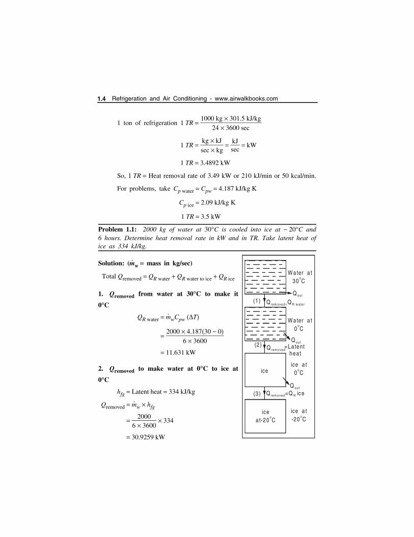
Problem 1.1: 2000 kg of water at 30C is cooled into ice at 20C and6 hours. Determine heat removal rate in kW and in TR. Take latent heat ofice as 334 kJ/kg.
Solution: (m
w mass in kg/sec)
Total Qremoved QR water QR water to ice QR ice
1. Qremoved from water at 30C to make it
0C
QR water m
wCpw T
2000 4.18730 0
6 3600
11.631 kW
2. Qremoved to make water at 0C to ice at
0C
hfg Latent heat 334 kJ/kg
Qremoved m
w hfg
2000
6 3600 334
30.9259 kW
Q o u t
Q o u t
Q o u t
Q re m o v e d =Q R w a te r
Q re m o v e d
Q =re m o v e d Q ic eR
W a ter a t 30 C
o
W a ter a t 0 C
o
ice a t 0 C
o
ice a t -20 C
o
ice
icea t-20 C
o
(1 )
(2 )
(3 )
=La tent hea t
1.4 Refrigeration and Air Conditioning - www.airwalkbooks.com
3. Qremoved to make ice from 0C to 20C: QR ice
QR ice m
iceCp ice Tice
2000 2.09 0 20
6 3600
3.8704 kW
Total heat removed
QR water QR water to ice QR ice
11.631 30.9259 3.8704
QR 46.4273 kW
Tonne of Refrigeration
TR QR
3.5
46.42733.5
13.265[. . . 1 TR 3.5 kW]
TR 13.265TR
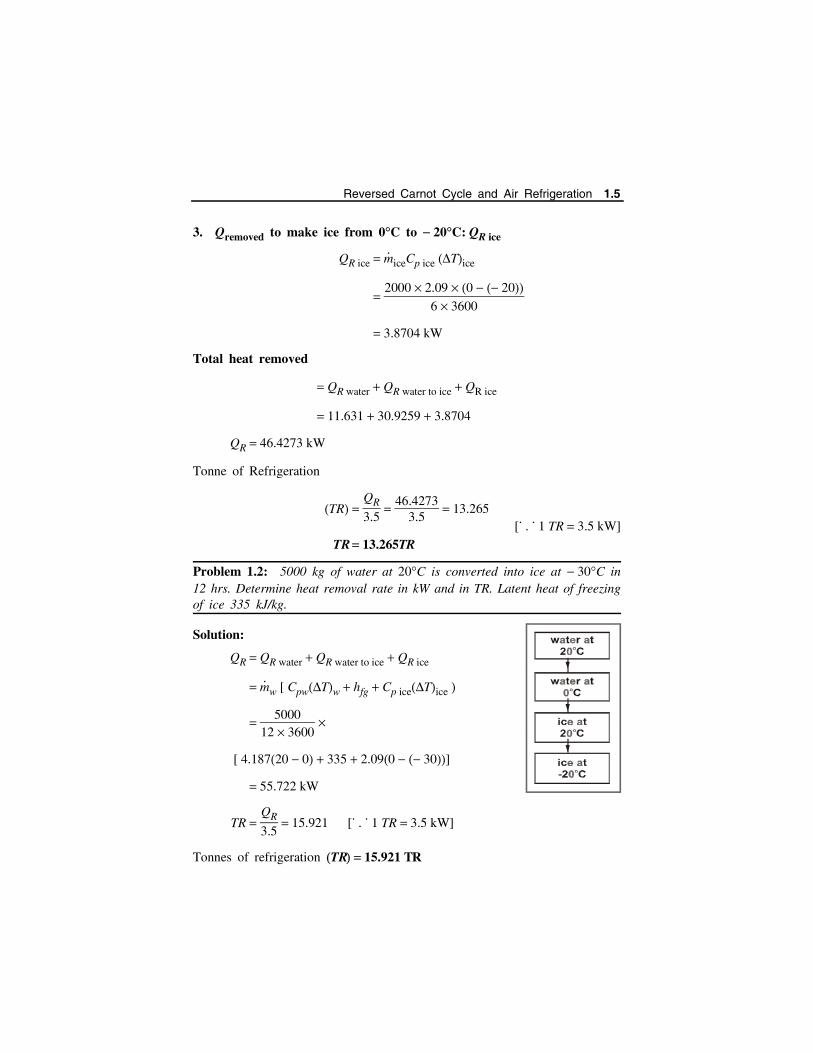
Problem 1.2: 5000 kg of water at 20C is converted into ice at 30C in12 hrs. Determine heat removal rate in kW and in TR. Latent heat of freezingof ice 335 kJ/kg.
Solution:
QR QR water QR water to ice QR ice
m
w [ CpwTw hfg Cp iceTice
5000
12 3600
[ 4.18720 0 335 2.090 30]
55.722 kW
TR QR
3.5 15.921 [. . . 1 TR 3.5 kW]
Tonnes of refrigeration TR 15.921 TR
Reversed Carnot Cycle and Air Refrigeration 1.5

Problem 1.3: Two refrigertor manufacturers claim that they developed anew model, working between 10C and 40C. First one claims a COP of7.0, while the second manufacturer claims a COP of 8.0. Which one you willprefer? Why? (Kerala University, 2013)
Solution: T1 40 273 313 K ; T2 10 273 263 K
COP for carnot cycle T2
T1 T2
263313 263
COP for carnot cycle 5.26
I won’t prefer both of the manufacturers, because, COP of a refrigerator
can’t be greater than carnot.
1.2 AIR REFRIGERATION SYSTEM
An air refrigeration system is a simple refrigeration cycle where in the
working fluid is air. It has relatively low coefficient of performance despite
its high operating costs. Hence, the usage of air refrigeration system has been
predominantly limited to aircraft refrigeration system due to its low weight
and the availability of cabin air as per the necessity. The notable feature about
this system is that the refrigerant remains in gaseous state throughout the
cycle.
It can be primarily divided into:
Closed system - It is also known as dense air refrigeration system.
In this system, the refrigerating air is contained within the
components of the system at all times. It usually operates in
pressures exceeding the atmospheric pressure.
Open system - In this system, the air is not circulated repeatedly
within the system. Cooled air from the turbine directly comes in
contact with the substances to be cooled, and is released into the
atmosphere. Hence, the operating pressure is limited to the pressure
inside the refrigerator. Consequently, an open cycle air refrigerating
system offers low COP with high operating costs.
1.6 Refrigeration and Air Conditioning - www.airwalkbooks.com

Closed cycle Open cycle
Can operate at high pressure. Limited to atmospheric pressures.
Moisture is eliminated. Moisture may choke the valvespresent in the system.
The size of the compressor andexpander is reduced due to use ofdense air.
The size of compressor directlydepends upon the pressure inside therefrigerator.
No fog is formed due to absence ofmoisture.
Fog formation due to moisture at theturbine. Hence a drier is needed.
Based on the principle of operation, an air refrigeration system can be
classified into three types.
1.2.1 Air Refrigeration Cycles
Refrigeration system is working under the following
1. Reversed carnot cycle
2. Bell-Coleman cycle
3. Aircraft refrigeration cycle
1.3 REVERSED CARNOT CYCLE Heat is removed from sink at low temperature to source at high
temperature by supplying work input.
COP-Coefficient of Performance
C.O.P means the ratio of the desired effect
(Refrigeration effect) to the work input.
C.O.P for reversed carnot cycle
Heat removed from cold body
Work input per cycle
Refrigeration effect
W
Q2
W
Q2
Q1 Q2
T2
T1 T2
Reversed Carnot Cycle and Air Refrigeration 1.7
Reversed carnot cycle will give more C.O.P. But this cycle is not
practically possible. So this cycle C.O.P is used to rate the other cycles C.O.P.
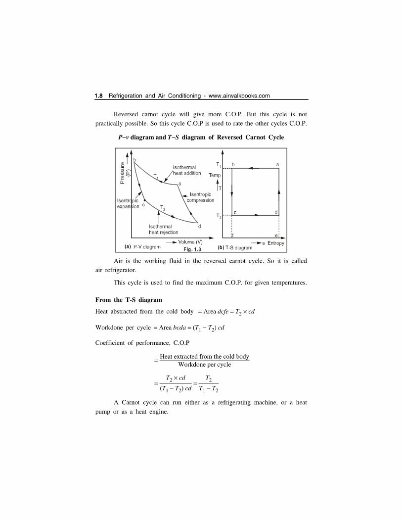
Pv diagram and TS diagram of Reversed Carnot Cycle
Air is the working fluid in the reversed carnot cycle. So it is called
air refrigerator.
This cycle is used to find the maximum C.O.P. for given temperatures.
From the T-S diagram
Heat abstracted from the cold body Area dcfe T2 cd
Workdone per cycle Area bcda T1 T2 cd
Coefficient of performance, C.O.P
Heat extracted from the cold body
Workdone per cycle
T2 cd
T1 T2 cd
T2
T1 T2
A Carnot cycle can run either as a refrigerating machine, or a heat
pump or as a heat engine.
Fig . 1.3 (a) (b)
f e
1.8 Refrigeration and Air Conditioning - www.airwalkbooks.com

1.3.1 Heat pump and refrigeration machines
(i) As a refrigerating machine
C.O.Pref
Heat extracted from cold body
Workdone per cycle
T2
T1 T2
(ii) As a Heat engine
C.O.Pheat engine Work obtained/cycleHeat supplied/cycle
T1 T2 cd
T1 ba
T1 T2
T1. . . cd ba
(iii) As a Heat Pump
If the desired effect is heat supplied to hot body, then the device is
called heat pump.
The C.O.P of heat pump Desired effect
Work input
Q1 Heat suppliedW
Q1
Q1 Q2
C.O.P Q1
Q1 Q2
T1
T1 T2 1
T2
T1 T2
So COP of heat pump is always greater than COP of refrigerator
working on reversed carnot cycle between same temperature limits
T1 and T2 by unity (1).
Problem 1.4: A/C room is to be maintained at 20C. The atmospheric
temperature is at 45C. The power given to the compressor is 3 kW.Determine the ton of refrigeration.
Heatpum p
TSource
1
TS ink
2
Q 1
Q 2
W
Co ld body
= H ea t supplied
Room
atm osphere
Ho t body
Fig . 1.4
Reversed Carnot Cycle and Air Refrigeration 1.9
Solution:
C.O.P T2
T1 T2
293
318 293 11.72
Also C.O.P Q2
W
Heat removed
Work input
11.72 Q2
3
Q2 3 11.72 35.16 kW
Q2 35.163.5
10.045 TR
Heat removal rate 10.045 TR
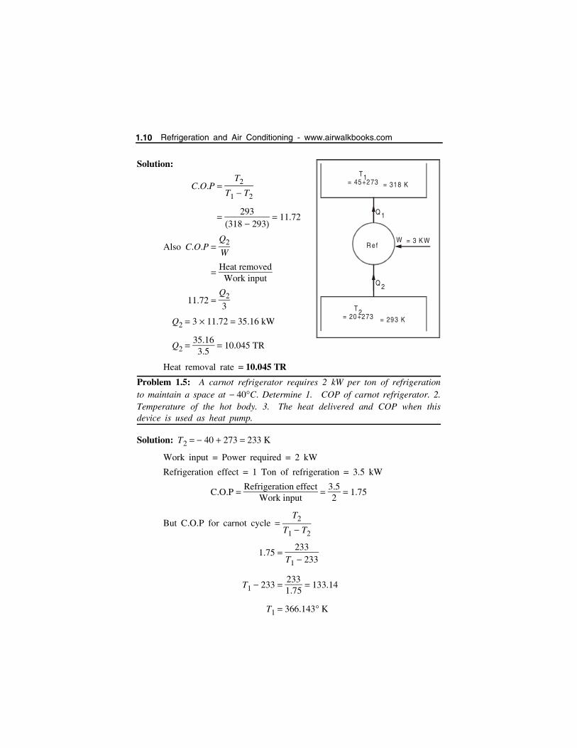
Problem 1.5: A carnot refrigerator requires 2 kW per ton of refrigerationto maintain a space at 40C. Determine 1. COP of carnot refrigerator. 2.Temperature of the hot body. 3. The heat delivered and COP when thisdevice is used as heat pump.
Solution: T2 40 273 233 K
Work input = Power required = 2 kW
Refrigeration effect = 1 Ton of refrigeration = 3.5 kW
C.O.P Refrigeration effect
Work input
3.52
1.75
But C.O.P for carnot cycle T2
T1 T2
1.75 233
T1 233
T1 233 2331.75
133.14
T1 366.143 K
R ef
T= 45+273
1
= 20+273T2
Q 1
Q 2
W
= 318 K
= 293 K
= 3 K W
1.10 Refrigeration and Air Conditioning - www.airwalkbooks.com

Q1 Q2 W
Q2 Refrigeration effect 3.5 kW
W Power required 2 kW
Q1 3.5 2 5.5 kW
C.O.P of heat pump Q1
W
5.52
2.75
Note: C.O.P of heat pump (2.75) = 1 + C.O.P of
Refrigerator (1.75).
Problem 1.6: A Carnot refrigerator requires 1.25 KW per tonne ofrefrigeration to maintain the temperature of 30C. Find (i) COP (ii)Temperature at which heat is rejected. [CUSAT, April 2017]
Solution:
T2 30 273 243 K
Work input 1.25 kW
Refrigeration effect 3.5 kW
But COP for carnot cycle T2
T1 T2
2.8 243
T1 243
Problem 1.7: A reversed carnot cycle is used to deliver 1680 kJ/sec to heatthe conditioned space. The heat is taken from atmosphere at 10C and
supplied to the conditioned space at 25C. Find the followings: powerrequired to run the system. [Kakinada University Nov-2011]
Given data:
T1 25C 298 K ; T2 10C 283 K
Q1 Heat delivered 1680 kJ/sec
COP REW
3.5
1.25
COP 2.8
T1 243 2432.8
T1 36.78 243
T1 329.78 K
D evice
Q 1
Q 2
W Heat pum p
T 1 =366.143
T2 =233
Reversed Carnot Cycle and Air Refrigeration 1.11
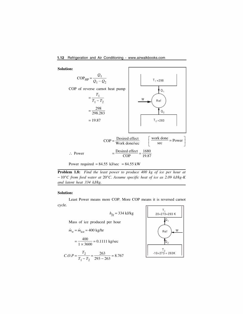
Solution:
COPHP Q1
Q1 Q2
COP of reverse carnot heat pump
T1
T1 T2
298
298.283
19.87
COP Desired effectWork done/sec
Power Desired effect
COP
168019.87
Power required 84.55 kJ/sec 84.55 kW
Problem 1.8: Find the least power to produce 400 kg of ice per hour at 10C from feed water at 20C. Assume specific heat of ice as 2.09 kJ/kg-Kand latent heat 334 kJ/kg.
Solution:
Least Power means more COP. More COP means it is reversed carnot
cycle.
hfg 334 kJ/kg
Mass of ice produced per hour
m
w m
ice 400 kg/hr
400
1 3600 0.1111 kg/sec
C.O.P T2
T1 T2
263293 263
8.767
work done
sec Power
Q 1
Q 2
W R ef
T 1 =298
T 2 =283
Ref
Q 1
Q 2
W
T120+273=293 K
T 2-10+273 = 263K
1.12 Refrigeration and Air Conditioning - www.airwalkbooks.com
To Find Least Power
C.O.P Net refrigeration effect
W
Q2
W
Q2 Qremoved from water at 20C to make it ice at 10C
Q2 m
w [ QR water QR water to ice QR ice ]
400
1 3600 [ CpwTw hfg Cp ice Tice ]
4003600
[ 4.187 20 0 334 2.090 10 ] 48.74 kW
Least power W Q2
C.O.P
48.748.767
5.56 kW
Relative COPRelative COP is the ratio of actual COP to the carnot COP. Relative
COP Actual COPCarnot COP
Actual COP Q2
W
QR
W
Qrejected or Qremoved
Power input
Carnot COP T2
T1 T2
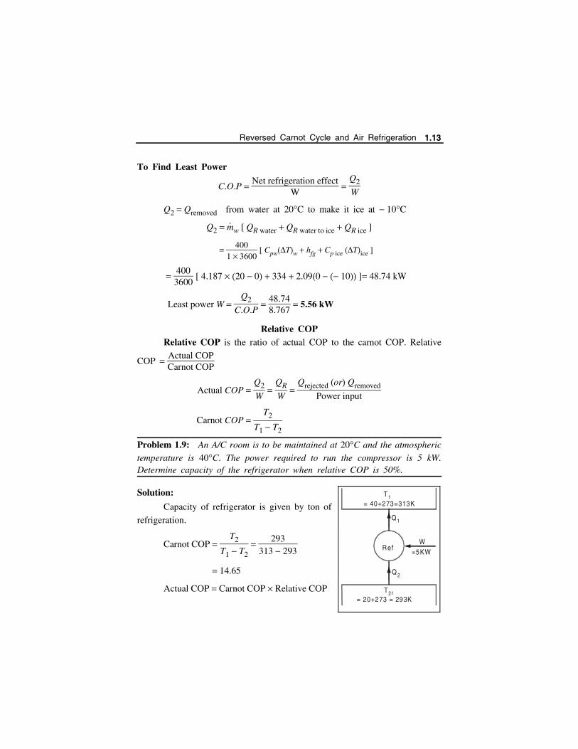
Problem 1.9: An A/C room is to be maintained at 20C and the atmospheric
temperature is 40C. The power required to run the compressor is 5 kW.Determine capacity of the refrigerator when relative COP is 50%.
Solution:
Capacity of refrigerator is given by ton of
refrigeration.
Carnot COP T2
T1 T2
293313 293
14.65
Actual COP Carnot COP Relative COP
Ref
Q 1
Q 2
W
T 1= 40+273=313K
T 22= 20+273 = 293K
=5KW
Reversed Carnot Cycle and Air Refrigeration 1.13
14.65 0.5
7.325
Also Actual COP Q2
W
Q2 Actual COP W 7.325 5
36.625 kW
Capacity of refrigerator Q2 in TR 36.625 kW
3.5 kW
10.46 TR
Problem 1.10: The capacity of the refrigerator working on reversed Carnotcycle is 280 tonnes when operating between 10C and 25C. Determine (i)
quantity of ice produced within 24 hours when water is supplied at 20C (ii)Minimum power required. Latent heat of ice is 335 kJ/kg
Solution:
(i) Heat removed from water at 25C to make it ice at 10C per
kg of water
Q2 [QR Water QRWater to rice QR ice]
[CPw Tw hfg CPice
Tice]
[4.187 20 0 335 2.09 0 10]
Q2 439 kJ/kg.
Heat extracting capacity of refrigerator 280 tonnes.
1 tonne 3.5 kW
Heat extracting capacity 280 3.5 980 kW.
Quantity of ice produced in 24 hours
Mice 980 24 60 60
439 192874 kgs or 193 tonnes.
1.14 Refrigeration and Air Conditioning - www.airwalkbooks.com

(ii) Minimum power required:
T1 25 273 298 K; T2 10 273 263 K
C.O.P T2
T1 T2
263298 263
7.51
C.O.P Heat extracting capacity
Power required
Power required Heat extracting capacity
C.O.P
9807.51
130.49 kW
Problem 1.11: Ice is formed at 0C from water at 20C the temperature of
the brine is 8C. Find out the kg of ice formed per kW-hr. Assume thatthe refrigeration cycle used is perfect reversed carnot cycle. Take latent heatof fusion of ice as 335 kJ/kg. (MBCET College Kerala - Dec 2016)
Given data: hfg 335 kJ /kg ;
Tw 20C 0C 20C 293 K ; Tice 0C 8C 8C 281 K
Solution:
Heat removed from water at 20C to make it ice at 8C per kg of
water.
Q2 m [QR water QR water to ice QR ice] [m 1 kg]
[4.187 20 335 2.09 8]
Q2 435.46 kJ/kg
1 kWhr 1 kJs
hr kJs
3600s
Capacity of refrigerator 3600 kJ
Quantity of ice produced per kWhr
m
ice heat extracting capacity
heat removed
3600435.46
m
ice 8.27 kg/hr
Reversed Carnot Cycle and Air Refrigeration 1.15
Problem 1.12: A cold storage plant is required to store 20 tonnes of food.The temperature of the food when supplied is 25C; storage temperature of
food is 8C. Specific heat of food above freezing point is 2.93 kJ/kgC.
Specific heat of food below freezing point 1.25 kJ/kgC; Freezing point of
food is 3C. Latent heat of food is 232 kJ/kg. If the cooling is achievedwith in 8 hrs; find (i) Capacity of the refrigeration plant (ii) C.O.P of
Carnot cycle (iii) If actual C.O.P is 1
5th of the Carnot C.O.P, find out the
power required to run the plant.
Solution:
(i) Heat removed from 1 kg of food
QR m
f [QR above QR Freeze Qbelow]
1 [CP above T Hfg CP below T]
1 [2.93 25 3 232 1.25 3 8]
Q4 320 kJ/kg
Heat removed by the plant
QR 20 1000
8 60 60
320 20 1000
8 3600 222.22 kJ/sec
222.22 kW
Capacity of Refrigeration plant
Heat removed by plant
3.5
222.253.5
63.49 tonnes or TR
(ii) COP of Carnot Cycle
C.O.P T2
T1 T2
8 273
25 273 8 273
265298 265
8.03.
(iii) Power required
Actual COP 15
COP 15
8.03 1.606
1.16 Refrigeration and Air Conditioning - www.airwalkbooks.com

Actual C.O.P Refrigeration or Heat removed
Workdone/min Power
222.22W
Power required W 222.221.606
138.49 kJ/sec or kW
Problem 1.13: 5600 kg of water available at 22C is to be converted to
ice at 4C in one day (24 hrs). If the sp. heat of ice is 2.09 kJ/kgK andthe latent heat is 335 kJ/kg, find the capacity of refrigeration system. (CUSAT June - 2011)
Given data:
Mass of water circulating 5600 kg
Temperature of water 22C
Solution:
heat removed from 1 kg,
QR m [QR1 QR2 QR3]
m [Cpw Tw hfg Cp ice Tice]
1 [4.187 22 0 335 2.09 0 4 ] 435.5
Heat removed from 1 kg, Q2 435.5 kJ/kg.
Total heat removed by plant
QR 5600
24 60 60
435.5 5600
24 60 60
28.23
Heat removed, Q2 28.23 kW
Capacity of the refrigerator,
heat removed by plant
3.5
28.233.5
8.06 tonnes
Temperature of ice 4CSpecific heat of ice 2.09 kJ/kgK
Latent heat 335 kJ/kg
Reversed Carnot Cycle and Air Refrigeration 1.17

1.3.1.1 Merits of Reversed Carnot Cycle
1. No risk of fire as compared to ammonia refrigerator.
2. Cheaper than other refrigerants.
3. The weight is lesser than other refrigeration system. For this reason, it
is used in air-crafts.
1.3.1.2 Demerits of Reversed Carnot Cycle (Limitations)
1. COP of this cycle is very low when compared to other refrigeration
system.
2. The weight of circulating air is more in this cycle than other systems.
1.4 BELL-COLEMAN CYCLE (Reversed Joule Cycle)If the isothermal processes in carnot cycle is replaced by constant
pressure processes, then the cycle is called Bell-coleman cycle.
Process 1-2
Air is compressed isentropically during first part of the stroke. During
the remainder stroke, the compressed air (at high temperature) is forced into
cooler at constant pressure.
waterout
waterin
Cooler3
2
Heat Exchanger
4
2Refrigerator
(cooler)
Compressor
Electricm otor
Bearing
Coup ling
Expander
3
Bearing
1
Closed cycle air-refrigeratorworking on Bell - Coleman cycle.
Fig. 1.5
Air
Air
Air
1.18 Refrigeration and Air Conditioning - www.airwalkbooks.com
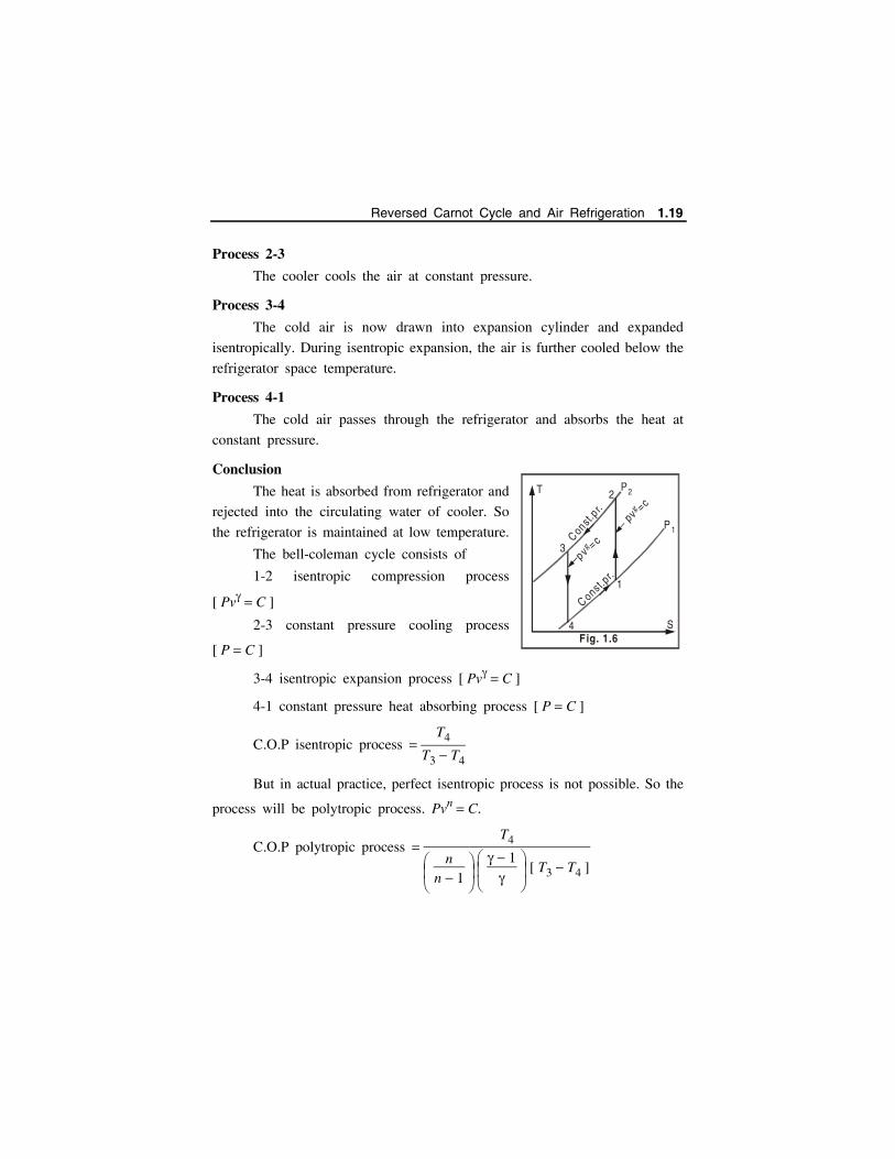
Process 2-3
The cooler cools the air at constant pressure.
Process 3-4
The cold air is now drawn into expansion cylinder and expanded
isentropically. During isentropic expansion, the air is further cooled below the
refrigerator space temperature.
Process 4-1
The cold air passes through the refrigerator and absorbs the heat at
constant pressure.
Conclusion
The heat is absorbed from refrigerator and
rejected into the circulating water of cooler. So
the refrigerator is maintained at low temperature.
The bell-coleman cycle consists of
1-2 isentropic compression process
[ Pv C ]
2-3 constant pressure cooling process
[ P C ]
3-4 isentropic expansion process [ Pv C ]
4-1 constant pressure heat absorbing process [ P C ]
C.O.P isentropic process T4
T3 T4
But in actual practice, perfect isentropic process is not possible. So the
process will be polytropic process. Pvn C.
C.O.P polytropic process T4
nn 1
1
[ T3 T4 ]
T
S
P 1
P2
3
4
Const.p
r.C onst.p
r.
pv=cg
pv=cg
2
1
Fig. 1.6
Reversed Carnot Cycle and Air Refrigeration 1.19

BELL-COLEMAN CYCLE
Polytropic Law
T2
T1 P2
P1
n 1n
; T3
T4 P3
P4
n 1n
P2
P1
n 1n
Heat absorbed from refrigerator (cold chamber) per kg of air CpT1 T4
Heat rejected in the cooling tower per kg of air CpT2 T3
Work done n
n 1 [ P2v2 P1v1 P3v3 P4v4 ]
n
n 1 R [ T2 T1 T3 T4 ]
C.O.P Heat absorbed
Work
Problem 1.14: A refrigerator working on Bell-coleman cycle operatesbetween pressure limits of 1.05 bar and 8.5 bar. Air is drawn from the coldchamber (refrigerator) at 10C. Air coming out of compressor is cooled to
30C before entering the expansion cylinder. Expansion and compression
follow the law Pv1.35 constant. Determine theoretical C.O.P. of the system. (JNTU - May/June 2009) Apr 2016 - Calicut University
P
V
Bell Colem an Cycle
1
23
4Q = Cp(T -T )absorbed 1 4
Isentrop ic expansion P V
(or)Polytrop ic
expansion (PV =c)n
=c
Isentrop ic compression
(or)Polytrop ic
compression (PV =c)n
pv =cQout
Constant pressure cooling
Constant pressure
heat absorption Fig. 1.7
1.20 Refrigeration and Air Conditioning - www.airwalkbooks.com
Solution:
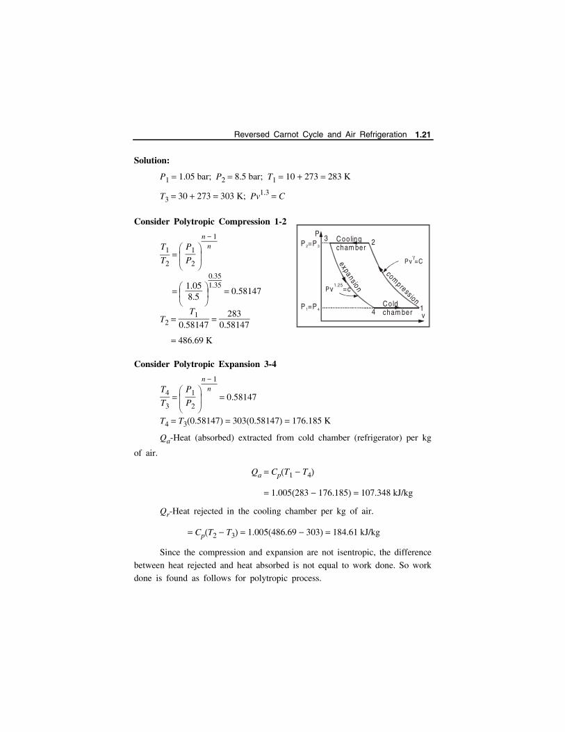
P1 1.05 bar; P2 8.5 bar; T1 10 273 283 K
T3 30 273 303 K; Pv1.3 C
Consider Polytropic Compression 1-2
T1
T2 P1
P2
n 1n
1.058.5
0.351.35
0.58147
T2 T1
0.58147
2830.58147
486.69 K
Consider Polytropic Expansion 3-4
T4
T3 P1
P2
n 1n
0.58147
T4 T30.58147 3030.58147 176.185 K
Qa-Heat (absorbed) extracted from cold chamber (refrigerator) per kg
of air.
Qa CpT1 T4
1.005283 176.185 107.348 kJ/kg
Qr-Heat rejected in the cooling chamber per kg of air.
CpT2 T3 1.005486.69 303 184.61 kJ/kg
Since the compression and expansion are not isentropic, the difference
between heat rejected and heat absorbed is not equal to work done. So work
done is found as follows for polytropic process.
C ooling cham ber
C old cham ber
P =P1 4
P =P2 3
P
1
23
4
expans ion
compression
Pv =c1.25
v
Pv=C
Reversed Carnot Cycle and Air Refrigeration 1.21
Work done
T1 283 K; T2 486.69 K; T3 303 K; T4 176.185 K
W n
n 1 R [ T2 T1 T3 T4 ]
1.350.35
0.287 [ 486.69 283 303 176.185 ]
85.1 kJ/kg
C.O.P Heat absorbed
Work done
107.34885.1
1.261
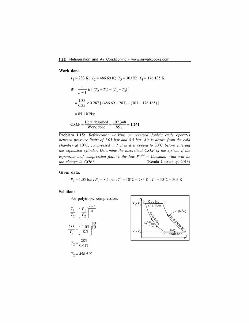
Problem 1.15: Refrigerator working on reversed Joule’s cycle operatesbetween pressure limits of 1.05 bar and 8.5 bar. Air is drawn from the coldchamber at 10C, compressed and, then it is cooled to 30C before enteringthe expansion cylinder. Determine the theoretical C.O.P of the system. If the
expansion and compression follows the law PV1.3 Constant, what will bethe change in COP? (Kerala University, 2013)
Given data:
P1 1.05 bar ; P2 8.5 bar ; T1 10C 283 K ; T3 30C 303 K
Solution:
For polytropic compression,
T1
T2 P1
P2
n 1n
283T2
1.058.5
0.31.3
T2 283
0.617
T2 458.5 K
C ooling cham ber
C old cham ber
P =P1 4
P =P2 3
P
1
23
4
expans ion
compression
Pv =c1.25
v
Pv=C
1.22 Refrigeration and Air Conditioning - www.airwalkbooks.com
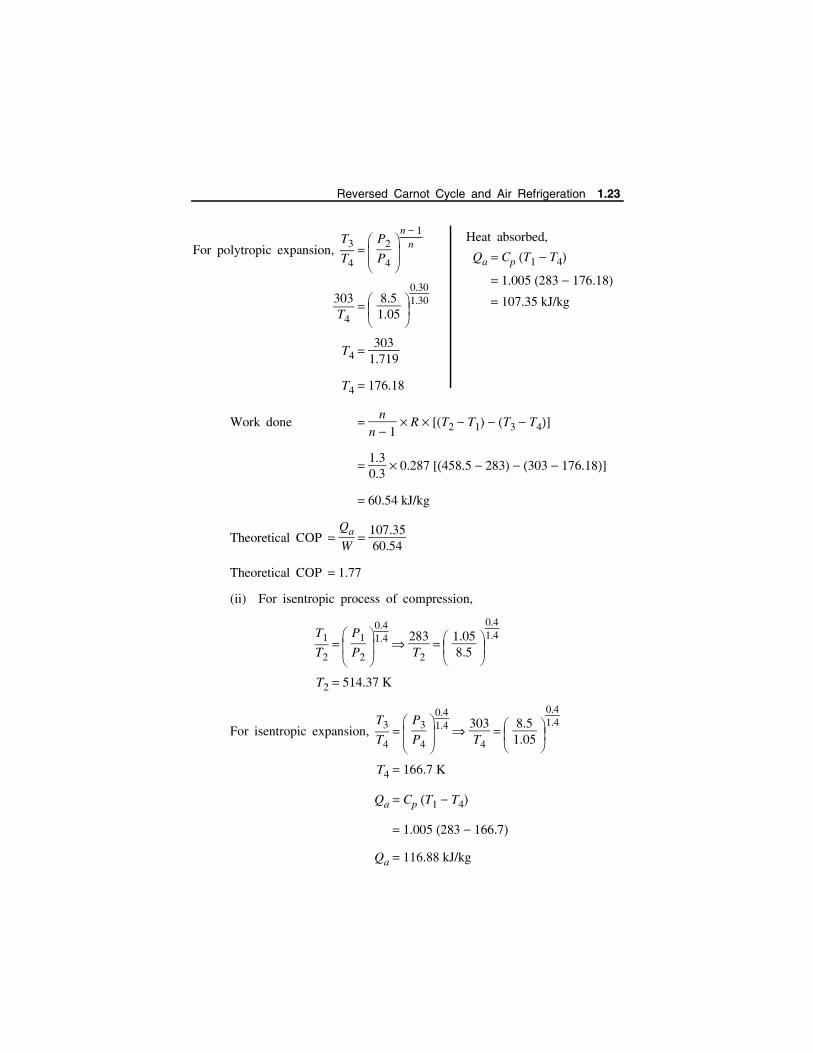
For polytropic expansion, T3
T4 P2
P4
n 1n
303T4
8.51.05
0.301.30
T4 303
1.719
T4 176.18
Work done n
n 1 R [T2 T1 T3 T4]
1.30.3
0.287 [458.5 283 303 176.18]
60.54 kJ/kg
Theoretical COP Qa
W
107.3560.54
Theoretical COP 1.77
(ii) For isentropic process of compression,
T1
T2 P1
P2
0.41.4
283T2
1.058.5
0.41.4
T2 514.37 K
For isentropic expansion, T3
T4 P3
P4
0.41.4
303T4
8.51.05
0.41.4
T4 166.7 K
Qa Cp T1 T4
1.005 283 166.7
Qa 116.88 kJ/kg
Heat absorbed,
Qa Cp T1 T4
1.005 283 176.18 107.35 kJ/kg
Reversed Carnot Cycle and Air Refrigeration 1.23

Compressor work done
1 mR T2 T1
1.40.4
1 0.287 514.37 283
50.225 kJ/min
Expander work done
1 mR T3 T4
1.40.4
1 0.287 303 166.7
136.9 kJ/kg
Net work done 136.9 50.225
86.675
COP Qa
W
116.8886.675
COP 1.35
If the process follows the law pV1.30 C, then the COP is greater than
the isentropic process.
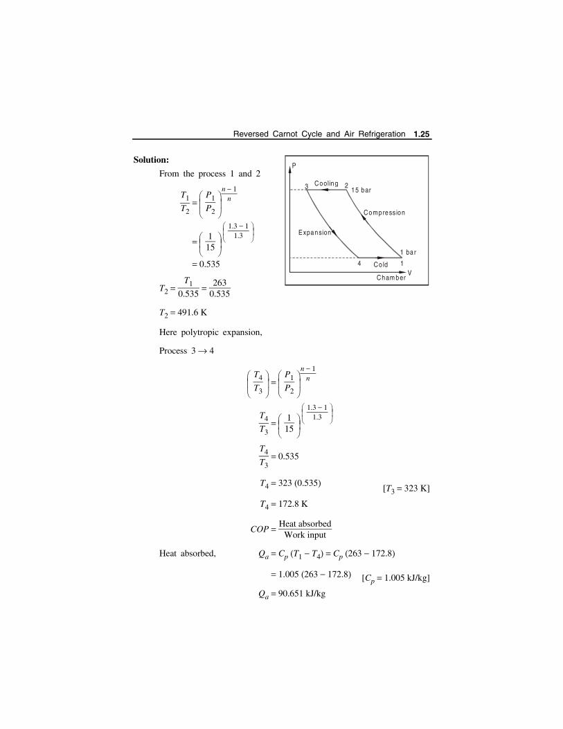
Problem 1.16: A refrigerator working on Bell-Coleman cycle (ReversedBrayton cycle) operates between 1 bar and 15 bar. Air is drawn from coldchamber at 10C. Air coming out of compressor is cooled to 50C before
entering the expansion cylinder. Polytropic law PV1.3 constant is followedduring expansion and compression. Find theoretical C.O.P. of the system.Take 1.4 and Cp 1.005 kJ/kgC for air.
(CUSAT, June 2011) JNTU Kakkinada University (May/april 2016)
Given data:
PV1.3 constant
P1 1 bar ; P2 15 bar
T1 10 273 263 K ; T3 50 273 323 K
Change in COP
1.77 1.35
0.422
1.24 Refrigeration and Air Conditioning - www.airwalkbooks.com
Solution:
From the process 1 and 2
T1
T2 P1
P2
n 1n
115
1.3 1
1.3
0.535
T2 T1
0.535
2630.535
T2 491.6 K
Here polytropic expansion,
Process 3 4
T4
T3 P1
P2
n 1n
T4
T3
115
1.3 1
1.3
T4
T3 0.535
T4 323 0.535[T3 323 K]
T4 172.8 K
COP Heat absorbed
Work input
Heat absorbed, Qa Cp T1 T4 Cp 263 172.8
1.005 263 172.8 [Cp 1.005 kJ/kg]
Qa 90.651 kJ/kg
3 2
4 1
Cooling
Compress ion
Expansion
Co ld
P
V
15 bar
1 ba r
Cham ber
Reversed Carnot Cycle and Air Refrigeration 1.25
Heat Rejected,
Qr Cp T2 T3 1.005 491.6 323
Qr 169.443 kJ/kg
Workdone,
T1 263 K ; T3 323 K ; T2 491.6 K ; T4 172.8 K
R 0.287
W n
n 1 R [T2 T1 T3 T4]
1.3
1.3 1 0.287 [491.6 263 323 172.8]
4.3 0.287 78.4
97.5 kJ/kg
COP Qa
W
90.65197.5
0.93
Problem 1.17: A refrigerator of 6 ton capacity working on Bell-coleman cyclehas an upper limit of pressure of 5 bar. The pressure and temperature at thestart of the compression are 1 bar and 15C respectively. The compressed air
is cooled at a constant pressure to a temperature of 40C enters the expansioncylinder. Assuming both expansion and compression processes to be isentropic with 1.4, calculate (i) C.O.P. (ii) Quantity of air in circulation per minute. (iii)Piston displacement of compressor and expander. (iv) Bore of compressor andexpansion cylinders. The refrigerating unit runs at 240 r.p.m. and is doubleacting. Stroke length = 250 mm. (v) Power required to drive the unit. For airtake 1.4 and Cp 1.005 kJ/kg K.
Solution:
Capacity 6T.R 6 3.5 21 kW
Refrigerating effect produced by the refrigeration.
P2 P3 5 bar; P1 P4 1 bar
T1 15 273 288 K; T3 40 273 313 K
1.26 Refrigeration and Air Conditioning - www.airwalkbooks.com
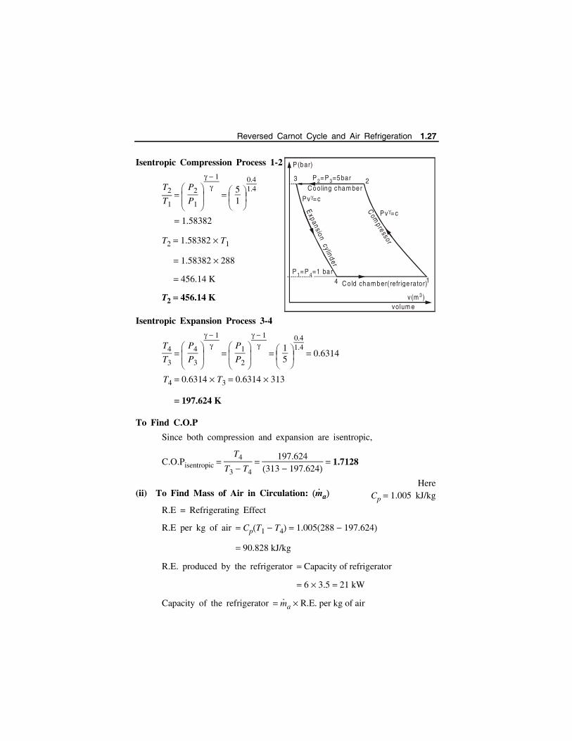
Isentropic Compression Process 1-2
T2
T1 P2
P1
1
51
0.41.4
1.58382
T2 1.58382 T1
1.58382 288
456.14 K
T2 456.14 K
Isentropic Expansion Process 3-4
T4
T3 P4
P3
1
P1
P2
1
15
0.41.4
0.6314
T4 0.6314 T3 0.6314 313
197.624 K
To Find C.O.P
Since both compression and expansion are isentropic,
C.O.Pisentropic T4
T3 T4
197.624313 197.624
1.7128
(ii) To Find Mass of Air in Circulation: m
a
R.E = Refrigerating Effect
R.E per kg of air CpT1 T4 1.005288 197.624
90.828 kJ/kg
R.E. produced by the refrigerator Capacity of refrigerator
6 3.5 21 kW
Capacity of the refrigerator m
a R.E. per kg of air
HereCp 1.005 kJ/kg
14
23C ooling cham ber
C o ld cham ber( refrige rator)
Com
pressor
Expansion cyl inder
Pv =c
Pv =c
P(bar)
v(m )3
volum e
P =P =5bar2 3
P =P =1 ba r1 4
Reversed Carnot Cycle and Air Refrigeration 1.27

where m
a Mass of air in circulation.
m
a Capacity of refrigerator
R.E. per kg of air
2190.828
kJ
sec kJ/kg
m
a 0.2312 kg/sec
(iii) To Find Piston Displacement of Compressor V
V Volume of air in circulation in m3/sec
Volume corresponding to point 1 i.e. V
1.
P1V
1 m
aRT1 [P1 in kPa ; 1 bar 1 102 kPa]
V
1 mRT1
P1
0.2312 0.287 288
1 102
0.1911 m3/sec
(iv) To Find Dia. of Compressor Cylinder
Vs Swept volume per stroke Vs V
1
2 N60
for double acting compressor.
N R.P.M. ;
Vs Swept volume per stroke
0.1911 60
2 240 m3 sec
sec 0.023887 m3
Vs 0.023887 m3
Also, Vs 4
dc2 L
Vs 0.023887 4
dc2 0.25
dc2 0.12165
dc 0.3488 m
where L Stroke length
dc dia. of compressor cylinder
1.28 Refrigeration and Air Conditioning - www.airwalkbooks.com

To Find Diameter of Expander Cylinder
V
4 Volume of air in circulation in m3/sec.
= Volume corresponding to point 4 is V
4.
P4V
4 m
aRT4
V
4 m
aRT4
P4
0.2312 0.287 197.624
1 102
0.13113 m3/sec
Vs Swept volume per stroke V
4
2 N/60 for double acting expander.
0.13113 60
2 240
0.01639 m3/sec
Vs 4
de2 L
0.01639 4
de2 0.25
(v) To Find the Power Required to Run the Unit
C.O.P R.EW
1.7128 6 3.5
W
where W Power required
W
6 3.51.7128
12.26 kW
Power required 12.26 kW
where de dia. of expander cylinder.
de2 0.08347
de 0.2889 m
Reversed Carnot Cycle and Air Refrigeration 1.29
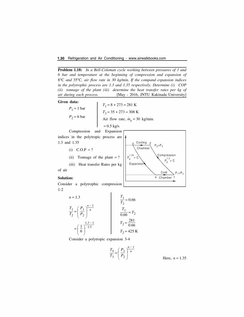
Problem 1.18: In a Bell-Coleman cycle working between pressures of 1 and6 bar and temperature at the beginning of compression and expansion of8C and 35C, air flow rate in 30 kg/min. If the compand expansion indicesin the polytrophic process are 1.3 and 1.35 respectively. Determine (i) COP(ii) tonnage of the plant (iii) determine the heat transfer rates per kg ofair during each process. [May - 2016, JNTU Kakinada University]
Given data:
P1 1 bar
P2 6 bar
Compression and Expansion
indices in the polytropic process are
1.3 and 1.35
(i) C.O.P ?
(ii) Tonnage of the plant ?
(iii) Heat transfer Rates per kg
of air
Solution:
Consider a polytrophic compression
1-2
n 1.3
T1
T2 P1
P2
n 1n
16
1.3 11.3
Consider a polytropic expansion 3-4
T4
T3 P1
P2
n 1n
Here, n 1.35
T1 8 273 281 K
T3 35 273 308 K
Air flow rate, m
a 30 kg/min.
0.5 kg/s
T1
T2 0.66
T1
0.66 T2
T2 2810.66
T2 425 K
3 2
4 1
P =P2 3
Cooling
Compress ion
Expansion
Co ld
P = C1.3
P =P1 4
Cham ber
Cham ber
v
P = C1.35
v
1.30 Refrigeration and Air Conditioning - www.airwalkbooks.com
T4
T3 16
1.35 11.35
Qa Heat absorbed from cold chamber per kg of air
Qa Cp T1 T4 1.005 281 193.6
Qa 87.4 kJ/kg
Q
a m Qa 0.5 87.4 43.7 kW
Qr Heat Rejected in the cooling chamber per kg of air
Qr Cp T2 T3 1.005 425 308
1.005 117.7
QR 117.6 kJ/kg
Workdone
T1 281 K, T2 425 K, T3 308 K ; T4 193.6 K
Workdone
n1
n1 1 R T2 T1
n2
n2 1 R T3 T4
1.30.3
0.287 425 281 1.350.35
0.287 308 193.6
179 126.6 52.36
52.36 kJ/kg
(i) COP
COP heat absorbed
workdone
87.452.36
1.67
COP 1.67
(ii) Tonnage of plant
TR Q
a
3.5
43.73.5
12.5
TR 12.5 ton
T4 0.628 T3
T4 0.628 308
T4 193.6 K
Reversed Carnot Cycle and Air Refrigeration 1.31

(iii) Heat transfer rate per kg of air
Qa 87.4 kJ/kg
QR 117.6 kJ/kg
Problem 1.19: A Bell-Coleman refrigerator is required to produce 6 tonnesof refrigerating effect with a cooler pressure of 11 bar and a refrigeratedspace or region at a pressure of 1.05 bar. The temperature of air leavingthe cooler is 38C and air leaving the room is 16C. Calculate: (i) Mass of air circulated per minute (ii) Compressor displacement required per minute (iii) Expander displacement required per minute (iv) COP and (v) Power required per tonne of refrigeration. (MBCET Dec-2016)
Given data:
Capacity 6 ton
6 3.5 kW
21 kW Refrigerating effect
So,
P2 P3 11 bar
P1 P4 1.05 bar
T1 16 273 289 K ; T3 38 273 311 K
Solution:
Isentropic compression process 1 2
T2
T1 P2
P1
1
111.05
1.4 1
1.4
T2
T1 1.96
V(m ) Volum e3
1.32 Refrigeration and Air Conditioning - www.airwalkbooks.com
T2 1.96 289
T2 565.4 K
Isentropic Expansion process, 3 4
T4
T3 P4
P3
1
P1
P2
1
T4
T3 1.0511
0.41.4
T4
T3 0.511
T4 0.511 311
T4 158.95 K
(i) Find mass of air circulated per minute m
a :
Capacity of the Refrigerator m
a R.E per kg of air
R.E Refrigerating effect.
R.E per kg of air Cp T1 T4
1.005 289 158.95
130.7 kJ/kg
R.E produced by the Refrigerator
Capacity of Refrigerator
6 3.5 21 kW
Reversed Carnot Cycle and Air Refrigeration 1.33
Then,
m
a Capacity of Refrigerator
R.E per kg of air
21130.7
m
a 0.161 kg/sec 9.64 kg/min
Qa Cp T1 T4 1.005 289 158.95 130.7 kJ/kg
Wc
1 R T2 T1
1.40.4
0.287 565.4 289 277.64
WE
1 R T3 T4
1.40.4
0.287 311 158.95 152.73
Wnet Wc WE 124.9 kJ/kg
COP Qa
Wnet
130.7124.9
1.045
(Or)
COPisentropic T4
T3 T4
158.95311 158.95
1.045
COP 1.045
Compressor displacement required per minute:
P1 V
1 m
a RT1
V
1 volume of air in circulation in m3/sec
V
1 m RT1
P1
0.161 0.287 289
1 102
V
1 0.134 m3/sec 8.01 m3/min
Power required per tonne of refrigeration.
C.O.P R.EW
1.045 6 3.5
W
1.34 Refrigeration and Air Conditioning - www.airwalkbooks.com
W
6 3.51.045
W
20.1 kW
Where, W
Power required
Expander displacement required per miniute V
4
V
4 m RT4 V
4
m RT4
P4
0.161 0.287 158.95
105
0.069 m3/s 4.197 m3/min
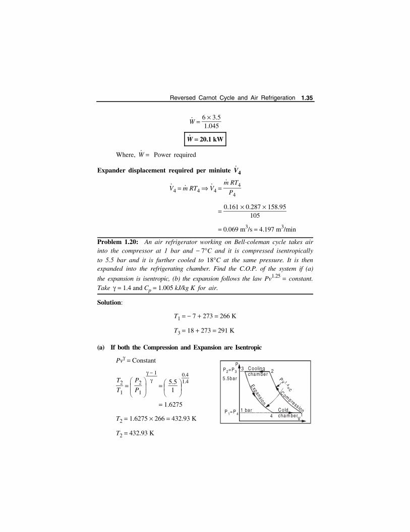
Problem 1.20: An air refrigerator working on Bell-coleman cycle takes airinto the compressor at 1 bar and 7C and it is compressed isentropically
to 5.5 bar and it is further cooled to 18C at the same pressure. It is thenexpanded into the refrigerating chamber. Find the C.O.P. of the system if (a)
the expansion is isentropic, (b) the expansion follows the law Pv1.25 constant.
Take 1.4 and Cp 1.005 kJ/kg K for air.
Solution:
T1 7 273 266 K
T3 18 273 291 K
(a) If both the Compression and Expansion are Isentropic
Pv Constant
T2
T1 P2
P1
1
5.51
0.41.4
1.6275
T2 1.6275 266 432.93 K
T2 432.93 K
C ooling cha m ber
C o ld cha m ber
P = P1 4
P = P2 3
1
23
4
Expansion
Comp ress ion
Pv=c
1 .4
1 ba r
5 .5bar
P
V
Reversed Carnot Cycle and Air Refrigeration 1.35

T4
T3 P4
P3
1
P1
P2
1
15.5
0.41.4
0.6144
T4 0.6144 T3 0.6144 291 178.797 K
C.O.P T4
T3 T4
178.797291 178.797
1.594
(or) C.O.P T1
T2 T1
266432.93 266
1.594
So, C.O.P. 1.594
(b) If the Compression is Isentropic and Expansion is Polytropic
T4T3
P4
P3
n 1n
15.5
0.251.25
0.7111
T4 0.7111 291 207 K
Work done
1 RT2 T1
nn 1
RT3 T4
1.40.4
0.287 433 266
1.250.25
0.287291 207
Qabsorbed from the Cold Chamber: Process 4-1
Qabsorbed CpT1 T4
1.005266 207
59.3 kJ/kg
C.O.P Qabsorbed
W
59.347.11
1.259
So, C.O.P 1.259
1
23
4
P
v
Pv =c
4 �
Pv =c1.25
1.36 Refrigeration and Air Conditioning - www.airwalkbooks.com
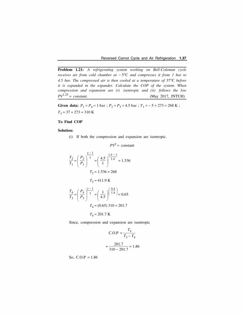
Problem 1.21: A refrigerating system working on Bell-Coleman cyclereceives air from cold chamber at 5C and compresses it from 1 bar to
4.5 bar. The compressed air is then cooled at a temperature of 37C beforeit is expanded in the expander. Calculate the COP of the system. Whencompression and expansion are (i) isentropic and (ii) follows the low
PV1.25 constant. (May 2017, JNTUH)
Given data: P1 P4 1 bar ; P2 P3 4.5 bar ; T1 5 273 268 K ;
T3 37 273 310 K
To Find COP
Solution:
(i) If both the compression and expansion are isentropic.
PV constant
T2
T1 P2
P1
1
4.51
1.4 11.4 1.536
T2 1.536 268
T2 411.9 K
T4
T3 P4
P3
1
14.5
0.41.4
0.65
T4 0.65 310 201.7
T4 201.7 K
Since, compression and expansion are isentropic
C.O.P T4
T3 T4
201.7
310 201.7 1.86
So, C.O.P 1.86
Reversed Carnot Cycle and Air Refrigeration 1.37

(ii) Both follows the law, PV1.25 constant.
Consider polytropic compression 1-2
T1
T2 P1
P2
n 1n
14.5
1.25 1
1.25
0.74
T1 0.74 T2
T2 2680.74
T2 362K
Consider polytropic expansion 3-4.
T4
T3 P1
P2
n 1n
0.74
T4
T3 0.74
T4 0.74 T3 0.74 310 229.4
T4 229.4 K
Qa Heat (absorbed) Extracted from cold chamber (refrigerator) per
kg of air
Qa Cp T1 T4
1.005 268 229.4
Qa 38.79 kJ/kg
3 2
4 1
P =P2 3
Cooling
Compression
Expansion
Gold
P = C.1 .25
P =P1 4 Cham ber
Cham ber
v
P
V
1.38 Refrigeration and Air Conditioning - www.airwalkbooks.com
Qr Heat Rejected in the cooling chamber per kg of air.
Qr Cp T2 T3
1.005 362 310
Qr 52.26 K
Since the compression and expansion are not isentropic, the difference
between heat rejected and heat absorbed is not equal to work done. So
workdone is found as follows for polytropic process.
Workdone
T1 268 K ; T2 362 K ; T3 310 K ; T4 229.4 K ;
W n
n 1 R [T2 T1 T3 T4]
1.25
1.25 1 0.287 [362 268 310 229.4]
W 19.3 kJ/kg
C.O.P Heat absorbed
Workdone
38.7919.3
2
C.O.P 2
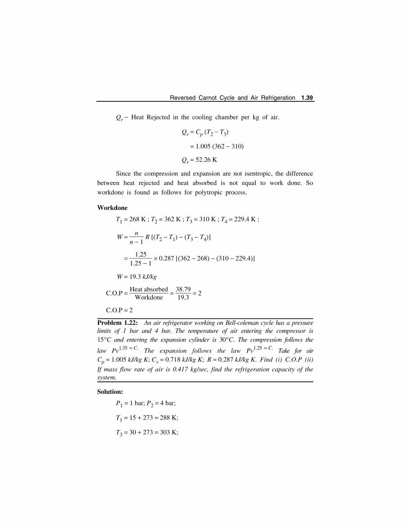
Problem 1.22: An air refrigerator working on Bell-coleman cycle has a pressurelimits of 1 bar and 4 bar. The temperature of air entering the compressor is15C and entering the expansion cylinder is 30C. The compression follows the
law Pv1.35 C. The expansion follows the law Pv1.25 C. Take for airCp 1.005 kJ/kg K; Cv 0.718 kJ/kg K; R 0.287 kJ/kg K. Find (i) C.O.P (ii)
If mass flow rate of air is 0.417 kg/sec, find the refrigeration capacity of thesystem.
Solution:
P1 1 bar; P2 4 bar;
T1 15 273 288 K;
T3 30 273 303 K;
Reversed Carnot Cycle and Air Refrigeration 1.39

To Find T2
T2
T1 P2
P1
n1 1
n1
41
0.351.35
1.4325
T2 1.4325 288 412.56 K
T2 412.56 K
To Find T4
T4
T3 P4
P3
n2 1
n2 P1
P2
n2 1
n2 14
0.251.25
0.75785
T4 0.75785 303 229.631 K
T4 229.631 K
Heat Absorbed from the Refrigerator (Cold Chamber) per kg of air(Refrigeration Effect/kg of air)
R.E./kg of air CpT1 T4 1.005288 229.631
58.661 kJ/kg
Work done
n1
n1 1 RT2 T1
n2
n2 1 RT3 T4
1.350.35
0.287412.56 288
1.250.25
0.287303 229.631
137.89 105.285
32.6055 kJ/kg
1.40 Refrigeration and Air Conditioning - www.airwalkbooks.com

C.O.P R.E/kg of air
W
58.66132.6055
1.799
Refrigeration Capacity
R.E in kW = R.E/kg of air m
where m Mass of air in circulation in kg/sec.
R.E in kW 58.661 0.417 24.46 kW
R.E in TR 24.46
3.5 6.989 ~ 7
Capacity 7 tons of Refrigeration
Problem 1.23: In a refrigerator working on Bell-Coleman cycle, air is drawninto the cylinder of the compressor from the cold chamber at a pressure of1.03 bar and temperature 12C, after isentropic compression to 5.5 bar, the
air is cooled at constant pressure to a temperature of 22C. The polytropic
expansion PV1.25 C then follows and the air expanded to 1.03 bar is passedto cold chamber. Determine (i) Work done per kg of air flow (ii) R.E/kgof air flow (iii) COP. Take 1.4 and Cp 1.3 kJ/kgK.
(Kakinada University Mar-2017)
Given data:
P1 1.03 bar ; T1 12C 273 285 K ; P2 5.5 bar ; T3 22 C 273 295 K
PV1.25 C ; 1.4 ; Cp 1.3 [ n 1.25]
Solution:
To find T2
Isentropic compression,
P1
P2
1
T1
T2
285T2
1.035.5
0.41.4
T2 460 K
Reversed Carnot Cycle and Air Refrigeration 1.41
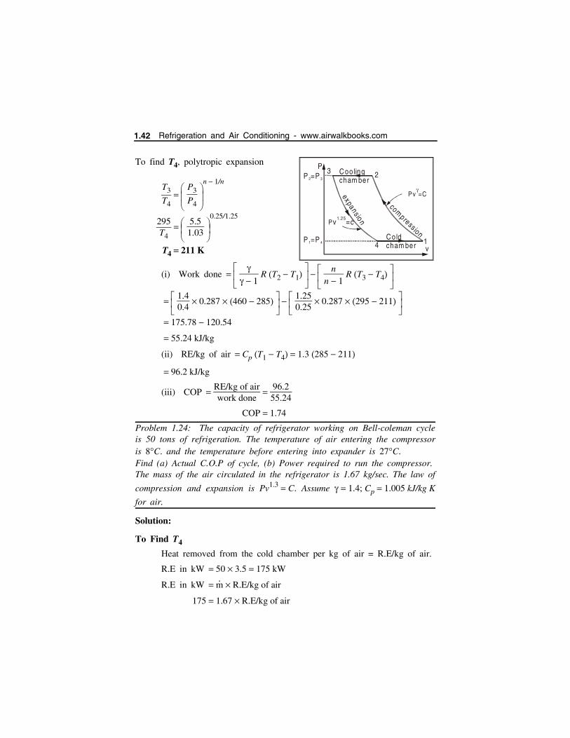
To find T4, polytropic expansion
T3
T4 P3
P4
n 1/n
295T4
5.51.03
0.25/1.25
T4 211 K
(i) Work done
1 R T2 T1
nn 1
R T3 T4
1.40.4
0.287 460 285 1.250.25
0.287 295 211
175.78 120.54
55.24 kJ/kg
(ii) RE/kg of air Cp T1 T4 1.3 285 211
96.2 kJ/kg
(iii) COP RE/kg of airwork done
96.255.24
COP 1.74
Problem 1.24: The capacity of refrigerator working on Bell-coleman cycleis 50 tons of refrigeration. The temperature of air entering the compressoris 8C. and the temperature before entering into expander is 27C.Find (a) Actual C.O.P of cycle, (b) Power required to run the compressor.The mass of the air circulated in the refrigerator is 1.67 kg/sec. The law of
compression and expansion is Pv1.3 C. Assume 1.4; Cp 1.005 kJ/kg K
for air.
Solution:
To Find T4
Heat removed from the cold chamber per kg of air = R.E/kg of air.
R.E in kW 50 3.5 175 kW
R.E in kW m
R.E/kg of air
175 1.67 R.E/kg of air
C ooling cham ber
C old cham ber
P =P1 4
P =P2 3
P
1
23
4
expans ioncom
pressionPv =c
1.25
v
Pv=C
1.42 Refrigeration and Air Conditioning - www.airwalkbooks.com
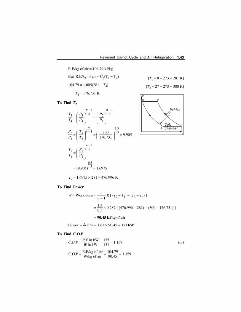
R.E/kg of air 104.79 kJ/kg
But R.E/kg of air CpT1 T4 [T1 8 273 281 K]
104.79 1.005281 T4 [T3 27 273 300 K]
T4 176.731 K
To Find T2
T3
T4 P3
P4
n 1n
P2
P1
n 1n
P2
P1 T3
T4
nn 1
300176.731
1.30.3
9.905
T2
T1 P2
P1
n 1n
9.9050.31.3 1.6975
T2 1.6975 281 476.996 K
To Find Power
W Work done n
n 1 R [ T2 T1 T3 T4 ]
1.30.3
0.287 [ 476.996 281 300 176.731 ]
90.45 kJ/kg of air
Power m W 1.67 90.45 151 kW
To Find C.O.P
C.O.P R.E in kWW in kW
175151
1.159 (or)
C.O.P R.E/kg of airW/kg of air
104.7990.45
1.159
Cold cham ber
1
23
4
Pv =c1.3
P
v
Reversed Carnot Cycle and Air Refrigeration 1.43
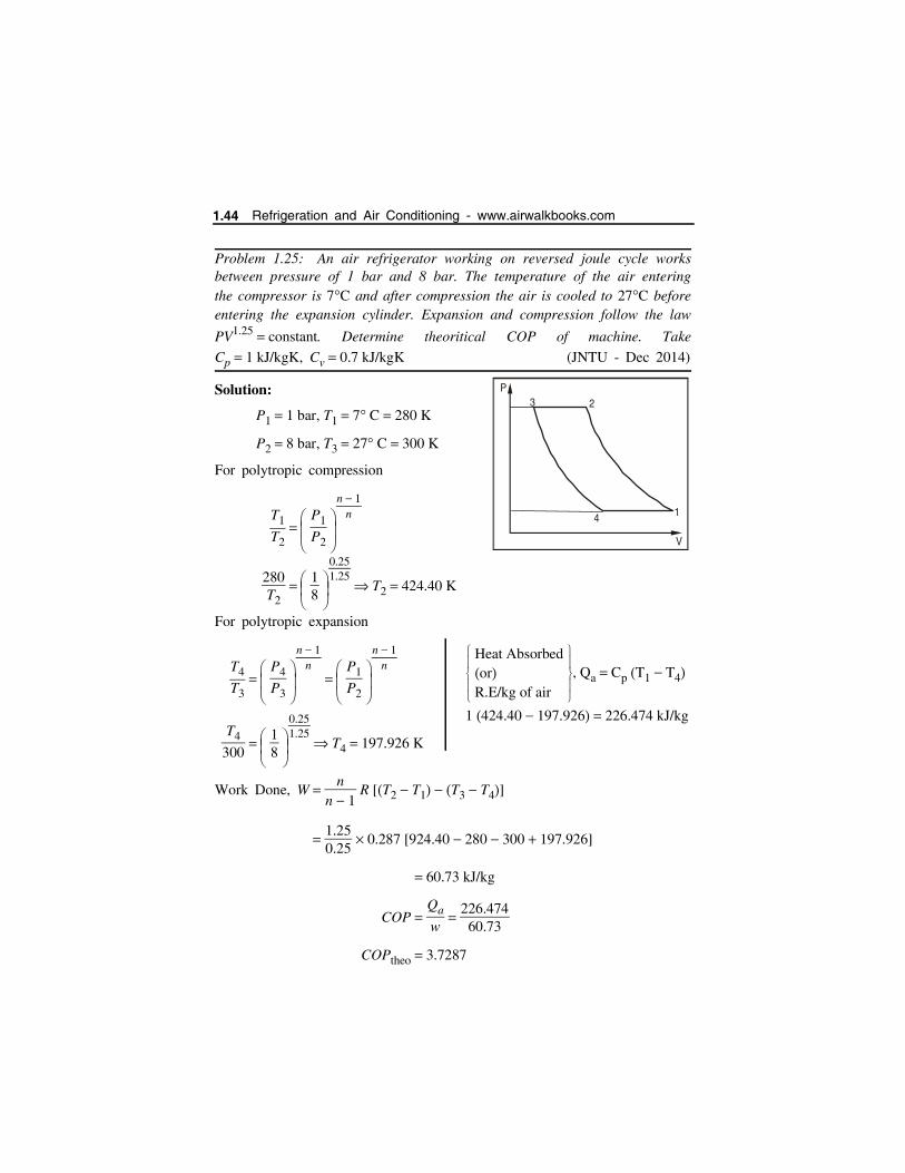
Problem 1.25: An air refrigerator working on reversed joule cycle worksbetween pressure of 1 bar and 8 bar. The temperature of the air enteringthe compressor is 7C and after compression the air is cooled to 27C beforeentering the expansion cylinder. Expansion and compression follow the law
PV1.25 constant. Determine theoritical COP of machine. Take
Cp 1 kJ/kgK, Cv 0.7 kJ/kgK (JNTU - Dec 2014)
Solution:
P1 1 bar, T1 7 C 280 K
P2 8 bar, T3 27 C 300 K
For polytropic compression
T1
T2 P1
P2
n 1n
280T2
18
0.251.25
T2 424.40 K
For polytropic expansion
T4
T3 P4
P3
n 1n
P1
P2
n 1n
T4
300 18
0.251.25
T4 197.926 K
Work Done, W n
n 1 R [T2 T1 T3 T4]
1.250.25
0.287 [924.40 280 300 197.926]
60.73 kJ/kg
COP Qa
w
226.47460.73
COPtheo 3.7287
Heat AbsorbedorR.E/kg of air
, Qa Cp T1 T4
1 424.40 197.926 226.474 kJ/kg
P
1
23
4
V
1.44 Refrigeration and Air Conditioning - www.airwalkbooks.com

Problem 1.26: A Bell-Coleman cycle operates between the pressure limitsof 1 bar and 8 bar. Air is drawn from the cold chamber at 282 K, compressedand then it is cooled to 302 K before entering the expansion cylinder.
Expansion and compression follow the law pV1.35 C. Calculate the
theoretical C.O.P of the system. For air 1.4 and Cp 1.003 kJ/kg-K.
[CUSAT - Nov - 2016]
Given Data:
P1 1 bar, P2 8 bar
T1 282 K, T3 302 K
Solution:
For polytropic process of compression,
T1
T2 P1
P2
n 1n
282T2
18
0.351.35
T2 282
0.583
T2 483.48 K
302T4
81
0.351.35
T4 302
1.714 176.14 K
Heat absorbed (or) RE/kg Cp T1 T4
1.003 282 176.14
Qa or RE/kg 106.177 kJ/kg
For polytropic expansion,
T3
T4 P3
P4
n 1n
P
3 2
141
8
V
p v = c1.35
Reversed Carnot Cycle and Air Refrigeration 1.45

Workdone n
n 1 R [T2 T1 T3 T4]
1.350.35
0.287 [483.48 282 302 176.14]
83.71 kJ/kg
Theoretical COP Qa
W
106.17783.71
1.268
Problem 1.27: In a Bell - Coleman refrigerator, air is taken in at 1 barand a temperature of 8C. The compression ratio is 4. The expansion and
compression follow the law PV1.2 constant. The air is cooled at the upper
pressure to 25C. Find the MEP of the cycle and the COP.(JNTU Dec 2014)
Given:
Compression ratio V1
V2 4; PV1.2 C
T1 8 C 265 K; P1 1 bar; T3 25 C 298 K
To find
The MEP of the cycle and COP
Solution:
P1 V1 n P2 V2
n
P2
P1 V1
V2
n
P2 1 41.2 5.27 bar
For polytropic compression
T2
T1 P2
P1
n 1n
T2 265 5.270.21.2
T2 349.58 K
V 2V 1
P
1
23
4
expa nsio n
compress ion
V
V S
1.46 Refrigeration and Air Conditioning - www.airwalkbooks.com
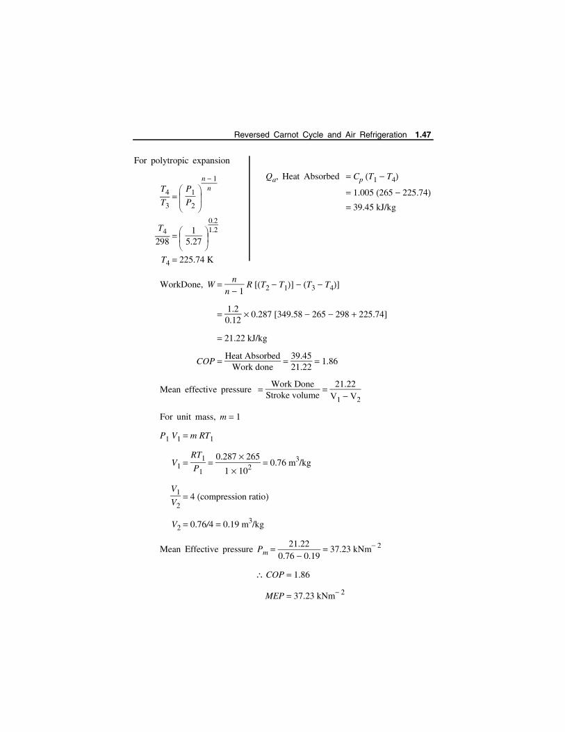
For polytropic expansion
T4
T3 P1
P2
n 1n
T4
298
15.27
0.21.2
T4 225.74 K
WorkDone, W n
n 1 R [T2 T1] T3 T4]
1.20.12
0.287 [349.58 265 298 225.74]
21.22 kJ/kg
COP Heat Absorbed
Work done
39.4521.22
1.86
Mean effective pressure Work Done
Stroke volume
21.22V1 V2
For unit mass, m 1
P1 V1 m RT1
V1 RT1
P1
0.287 265
1 102 0.76 m3/kg
V1
V2 4 compression ratio
V2 0.76/4 0.19 m3/kg
Mean Effective pressure Pm 21.22
0.76 0.19 37.23 kNm 2
COP 1.86
MEP 37.23 kNm 2
Qa, Heat Absorbed Cp T1 T4
1.005 265 225.74 39.45 kJ/kg
Reversed Carnot Cycle and Air Refrigeration 1.47
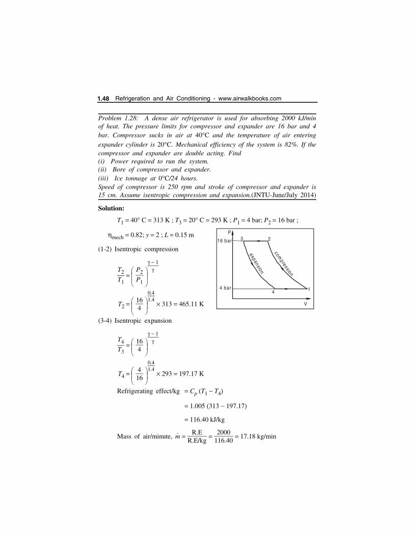
Problem 1.28: A dense air refrigerator is used for absorbing 2000 kJ/minof heat. The pressure limits for compressor and expander are 16 bar and 4bar. Compressor sucks in air at 40C and the temperature of air entering
expander cylinder is 20C. Mechanical efficiency of the system is 82%. If thecompressor and expander are double acting. Find(i) Power required to run the system. (ii) Bore of compressor and expander.(iii) Ice tonnage at 0C/24 hours. Speed of compressor is 250 rpm and stroke of compressor and expander is15 cm. Assume isentropic compression and expansion.(JNTU-June/July 2014)
Solution:
T1 40 C 313 K ; T3 20 C 293 K ; P1 4 bar; P2 16 bar ;
mech 0.82; y 2 ; L 0.15 m
(1-2) Isentropic compression
T2
T1 P2
P1
1
T2 164
0.41.4
313 465.11 K
(3-4) Isentropic expansion
T4
T3 164
1
T4
416
0.41.4
293 197.17 K
Refrigerating effect/kg Cp T1 T4
1.005 313 197.17
116.40 kJ/kg
Mass of air/minute, m
R.ER.E/kg
2000
116.40 17.18 kg/min
4 bar
16 bar
P
1
23
4
expans ion
compress ion
V
1.48 Refrigeration and Air Conditioning - www.airwalkbooks.com
Compressor work Wcomp
1 mR T2 T1
1.40.4
17.18 0.287 465.11 313
2625 kJ/min
Expander work Wexp
1 mR T3 T4
1.40.4
17.18 0.287 293 197.17
1653.76 kJ/min
Network done W 2625 1653.76 971.23 kJ/min
Power required P 971.23
60 16.18 kW
Actual power P
mech
16.180.82
19.73 kW
Bore of compressor
V
1 m RT1
P1
17.18 0.287 313
4 102
3.85 m3/min
V1 per stroke 3.85
2 250 7.7 10 3 m3
[. . .2 for double acting]
V1 4
dc2 l
7.7 10 3 4
dc2
15100
dc 0.255 m 255 mm
Reversed Carnot Cycle and Air Refrigeration 1.49
Bore of expander
V
4 m RT4
P4
17.18 0.287 197.17
4 102
2.43 m3/min
V4 per stroke 2.43
2 250 4.86 10 3 m3
V4 4
de2 l
4.86 10 3 4
de2
15100
de 0.203 m 203 mm
To find Ice tonnage
Heat to be removed from water at 0C to ice at 0 C
Refrigeration effect in kJ/24 hours R.E kJ/min 60 24
2880000 kJ/day
Ice produced RE/ day
Latent heat of ice
2880000335
8597.01 kg
8.597 tonnes
Problem 1.29: A dense closed cycle air-refrigeration system workingbetween 4 bar and 16 bar extracts 120 MJ of heat per hour. The air entersthe compressor at 5C and into the expander at 20C. Assuming the unitruns at 300 r.p.m. find: (a) kW required to run the unit, (b) bore ofcompressor, and (c) refrigerating capacity in tons of ice at 0C per day. Take the followings: Compressor and expander are double acting and stroke for compressor andexpander 30 cm.
Mechanical efficiency of compressor 80%.
Mechanical efficiency of expander 85%.
Latent heat ice 336 kJ/kg. Assume the compression and expansion are isentropic. (USAT, April 2016)
1.50 Refrigeration and Air Conditioning - www.airwalkbooks.com

Given data:
P1 4 bar
P2 16 bar
T1 5C 278 K
T3 20C 293 K
L 0.3 m
RE 120 MJ/hr 120 103 kJ/h
Solution:
Isentropic compression,
T1
T2 P1
P2
1
278T2
416
0.41.4
T2 278
0.673
T2 413 K
Isentropic expansion,
T3
T4 P3
P4
1
293T4
164
0.41.4
T4 293
1.486 197.17 K
N 300 rpm
mechcom
80%
mechexp
85%
hfg ice 336 kJ/kg
Refrigerating effect/kg Cp T1 T4
1.005 278 197.17
R.E/kg 81.23
3 2
4 1
P
V
4 Bar
16 B ar
Reversed Carnot Cycle and Air Refrigeration 1.51
Mass of air/minute, m
RERE/kg
120 103
81.23
1.477 103 kg/hr
24.62 kg/min
Compressor work
1 m R T2 T1
1.40.4
24.62 0.287 413 278
3338.65 kJ/min
Expander work
1 mR T3 T4
1.40.4
24.62 0.287 293 197.17
2369.95 kJ/min
Net workdone 3338.65 2369.95
968.7 kJ/min
Power required Work done
60 16.145 kW
Actual power P
mech
16.1450.8
Actual power 20.1813 kW
(ii) Bore of compressor
V
1 m RT1
P1
24.62 0.287 278
4 102
4.91 m3/min V
s
Vs per stroke V
1
2 N
4.912 300
8.18 10 3 m3
[N 300 rpm][2 for Double acting]
1.52 Refrigeration and Air Conditioning - www.airwalkbooks.com
But, Vs 4
dc2 L
8.18 10 3 4
0.3 dc2
dc 186 mm Bore of compressor cylinder
(iii) Refrigeration capacity in tons
Refrigeration effect in kJ/24 hours RE kJ/hr 24
120 103 24
2.88 106 kJ/day
Ice produced RE/day
Latent heat of ice
2.88 106
336 8571.4 kg/day
8.571 tonnes/day
1.5 AIRCRAFT REFRIGERATION SYSTEM (AIR REFRIGERATION FOR AIRCRAFTS)
Simple cycle of air refrigeration system
A simple air refrigeration is shown in Fig. 1.8. The components of the
system are: the compressor driven by a gas turbine, a heat exchanger, a cooling
turbine and cooling air fan. The air required for refrigeration system is bled off
from the main compressor. The high pressure and high temperature air is cooled
in the heat exchanger and it is further cooled in the cooling turbine
The T s diagram for a simple air cooling system is shown in Fig.1.9
The various processes are given here.
1. Ramming process: The ambient air with P1 and T1 is rammed
isentropically to the pressure P2 and temperature T2 (1-2). Because of internal
friction, the temperature of the rammed air is more than T2. Thus the actual
ramming process is shown by the curve 1 2. During the ideal (or) actual
ramming process, the total enthalpy remains constant i.e. h2 h2 and
T2 T2.
dc2 0.0347
dc 0.186 m
Reversed Carnot Cycle and Air Refrigeration 1.53
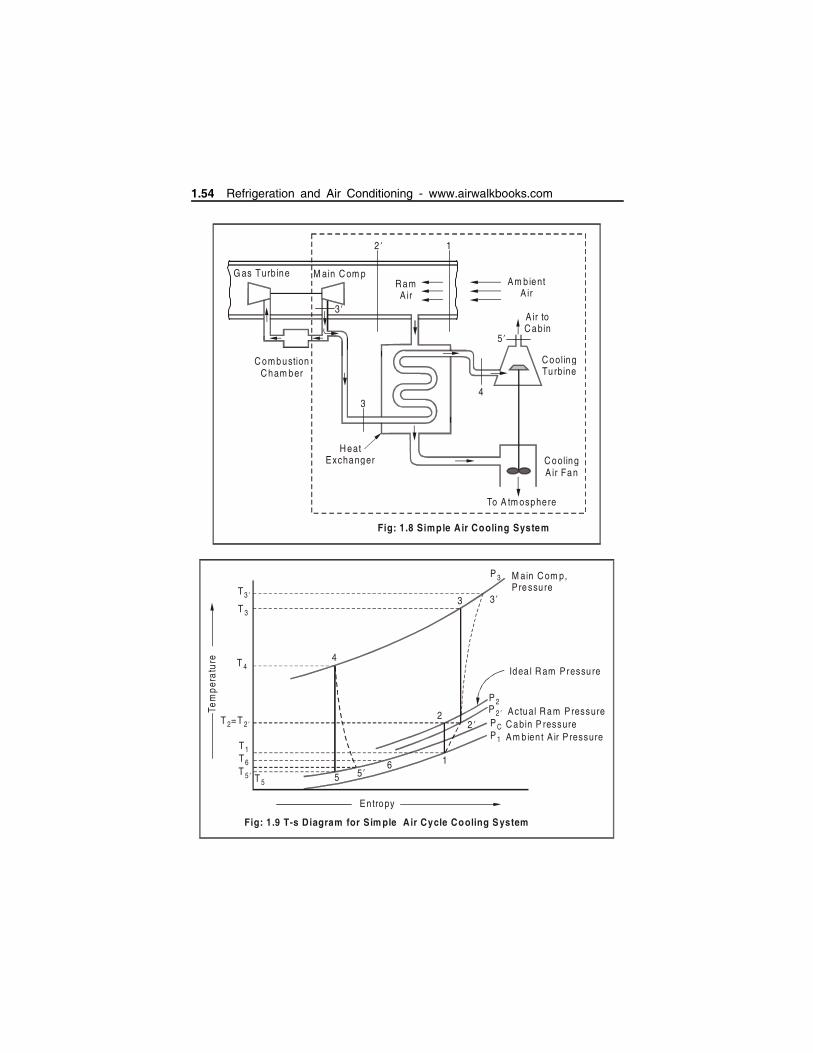
Fig: 1.8 Simple Air Cooling System
G as Turb ine M ain C om pR am A ir
Am b ient A ir
A ir to C abin
C ooling Tu rbine
H eat Exchanger C ooling
A ir Fan
To A tm osphere
C om bustion C ham ber
34
5 ’
2 ’ 1
3 ’
3 3 ’
P 3 M ain C om p, P re ssu re
Idea l R am Pressure T 4
4
T 3
T3 ’
1
22 ’
5 5 ’6
En tropy
Tem
per
atu
re
T =T2 2 ’
T1T6T 5 ’ T 5
P 2P 2 ’P CP 1
Actual R am Pressure C abin P ressure Am b ien t A ir P ressure
Fig: 1.9 T-s Diagram for Sim ple Air Cycle Cooling System
1.54 Refrigeration and Air Conditioning - www.airwalkbooks.com
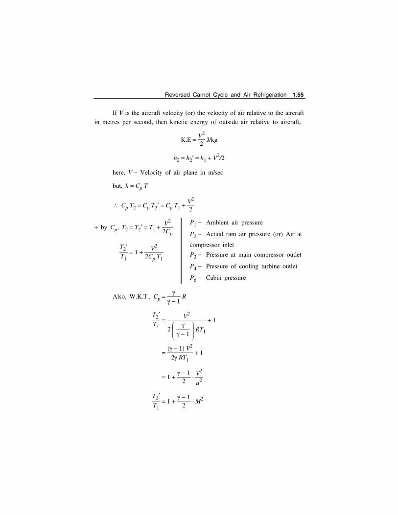
If V is the aircraft velocity (or) the velocity of air relative to the aircraft
in metres per second, then kinetic energy of outside air relative to aircraft,
K.E V2
2 J/kg
h2 h2 h1 V2/2
here, V Velocity of air plane in m/sec
but, h Cp T
Cp T2 Cp T2 Cp T1 V2
2
by Cp, T2 T2 T1 V2
2Cp
T2T1
1 V2
2Cp T1
Also, W.K.T., Cp
1 R
T2T1
V2
2
1 RT1
1
1 V2
2 RT1 1
1 1
2 V
2
a2
T2T1
1 1
2 M2
P1 Ambient air pressure
P2 Actual ram air pressure (or) Air at
compressor inlet
P3 Pressure at main compressor outlet
P4 Pressure of cooling turbine outlet
P6 Cabin pressure
Reversed Carnot Cycle and Air Refrigeration 1.55

Where, a RT1 is the local sonic velocity.
M Va
is the Mach number of flight.
The stagnation pressure P2 is given by,
P2
P1 T2
T1
1
(Isentropic law)
The ram efficiency is given by,
ram Actual pressure rise
Reversible adiabatic pressure rise
P2 P1
P2 P1
2. Compression process: The isentropic compression of air in the main
compressor is shown as 2 3. In actual practice, because of internal friction,
due to irreversibilities, the actual compression is represented by the curve
2 3. The work done during the compression process is given by
WC ma Cp T3 T2
where, ma Mass of air bled from the main compressor for refrigeration
purposes.
3. Cooling process: The compressed air is cooled by the ram air in the
heat exchanger as shown by the curve 3 4 in Fig.In actual practice, there
is a pressure drop in the heat exchanger. The temperature of air decreases
from T3 to T4.
QR ma Cp T3 T4
4. Expansion process: The cooled air is now expanded isentropically in
the cooling turbines shown by the curve 4 5. In actual practice, because of
internal friction due to irreversibilities, the actual expansion in the cooling
turbine is shown by the curve 4 5. The work done by the cooling turbine
during this expansion process is given by
1.56 Refrigeration and Air Conditioning - www.airwalkbooks.com

WT ma Cp T4 T5
The work of this turbine is used to drive the cooling air fan which
draws cooling air from the heat exchanger.
5. Refrigeration process: The air from the cooling turbine (i.e. after
expansion) is sent to the cabin and cock pit where it gets heated by the heat
of equipment and occupants. This process is shown by the curve 5 6 in
Fig. The refrigerating effect produced or heat absorbed is given by
RE ma Cp T6 T5
where, T6 Inside temperature of cabin.
T5 Exit temperature of cooling turbine.
We know that C.O.P. of the air cycle
Refrigerating effect produced
Work done
ma Cp T6 T5ma Cp T3 T2
T6 T3T3 T2
Assumptions
1. The work done by the cooling turbine is entirely used to blow air
through heat exchanger.
2. The kinetic energy converted to pressure energy in ram is not
considered.
3. If TR in the ton of refrigeration ie the cooling load in the cabin, then
the air required for the refrigeration purpose,
ma TR 210
Cp T6 T5 kg/min or
TR 3.5
Cp T6 T5 kg/s
Power required for the refrigeration system,
P ma Cp T3 T2
60 kW
and C.O.P. of the refrigerating system
Reversed Carnot Cycle and Air Refrigeration 1.57
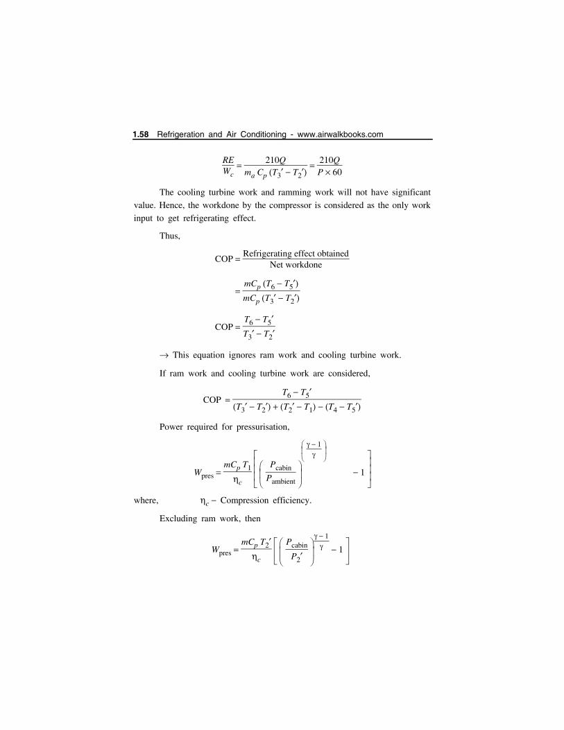
REWc
210Q
ma Cp T3 T2
210QP 60
The cooling turbine work and ramming work will not have significant
value. Hence, the workdone by the compressor is considered as the only work
input to get refrigerating effect.
Thus,
COP Refrigerating effect obtained
Net workdone
mCp T6 T5mCp T3 T2
COP T6 T5T3 T2
This equation ignores ram work and cooling turbine work.
If ram work and cooling turbine work are considered,
COP T6 T5
T3 T2 T2 T1 T4 T5
Power required for pressurisation,
Wpres mCp T1
c
Pcabin
Pambient
1
1
where, c Compression efficiency.
Excluding ram work, then
Wpres mCp T2
c Pcabin
P2
1
1
1.58 Refrigeration and Air Conditioning - www.airwalkbooks.com
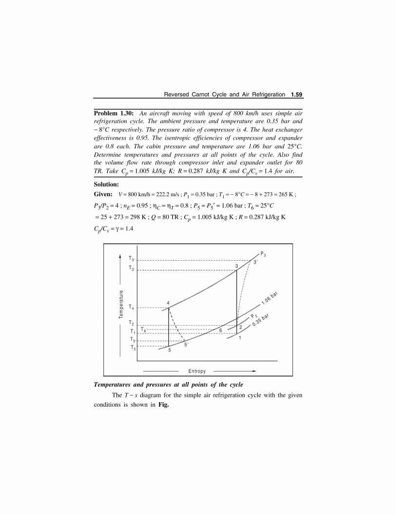
Problem 1.30: An aircraft moving with speed of 800 km/h uses simple airrefrigeration cycle. The ambient pressure and temperature are 0.35 bar and 8C respectively. The pressure ratio of compressor is 4. The heat exchangereffectiveness is 0.95. The isentropic efficiencies of compressor and expanderare 0.8 each. The cabin pressure and temperature are 1.06 bar and 25C.Determine temperatures and pressures at all points of the cycle. Also findthe volume flow rate through compressor inlet and expander outlet for 80TR. Take Cp 1.005 kJ/kg K; R 0.287 kJ/kg K and Cp/Cv 1.4 for air.
Solution:
Given: V 800 km/h 222.2 m/s ; P1 0.35 bar ; T1 8C 8 273 265 K ;
P3/P2 4 ; nE 0.95 ; C T 0.8 ; P5 P5 1.06 bar ; T6 25C
25 273 298 K ; Q 80 TR ; Cp 1.005 kJ/kg K ; R 0.287 kJ/kg K
Cp/Cv 1.4
Temperatures and pressures at all points of the cycle
The T s diagram for the simple air refrigeration cycle with the given
conditions is shown in Fig.
6
1
2
4
55 ’
33 ’
P 3
En tropy
Tem
pera
ture
T 3
T 3 ’
T 4
T 2
T 1T 6
T5
T5 ’
1 .06 bar
0.35 b arP 2
Reversed Carnot Cycle and Air Refrigeration 1.59
Let T2 and P2 Stagnation temperature and pressure of the ambient airentering the compressor.
T3 and P3 Temperature and pressure of the air leaving thecompressor after isentropic compression.
T3 Actual temperature of the air leaving the compressor.
T4 Temperature of the air leaving the heat exchanger (or)entering the expander.
P4 Pressure of the air leaving the heat exchanger (or)entering the expander P3 P3
T5 Temperature of the air leaving the expander afterisentropic expansion,
T3 Actual temperature of the air leaving the expander.
T2 T1 V2
2 Cp 265
222.22
2 1005 289.6 K
and P2
P1 T2
T1
1
289.6265
1.41.4 1
1.03
P2 P1 1.03 0.35 1.03 0.36 bar
Since P3/P2 4 (Given),
P3 P2 4 0.36 4 1.44 bar
For isentropic compression process 2-3,
T3
T2 P3
P2
1
4
1.4 11.4 1.49
T3 289.6 1.49 430.34 K
We also know that isentropic efficiency of the compressor,
1.60 Refrigeration and Air Conditioning - www.airwalkbooks.com
c Isentropic temperature rise
Actual temperature
T3 T2
T3 T2
0.8 430.34 289.6
T3 289.6
T3 289.6 140.74
0.8 175.9
T3 465.53 K
Effectiveness of the heat exchanger H,
0.95 T3 T4
T3 T2
465.53 T4
465.53 289.6
T4 298.4
and P4 P3 1.44 bar
We know that for isentropic expansion process 4-5,
T5
T4 P5
P4
1
1.061.44
1.4 11.4
0.916
T5 298.4 0.916 273.4 K
Now isentropic efficiency of the expander,
E Actual temperature rise
Isentropic temperature rise
T4 T5T4 T5
0.8 298.4 T5
298.4 273.4
T5 298.4 20 278.4 K
Let V2 Volume flow rate through the compressor inlet, and
V5 Volume flow rate through the expander outlet.
We know that mass flow rate of air,
Reversed Carnot Cycle and Air Refrigeration 1.61

m
a RE 210
Cp T6 T5
80 210
1.005 298 278.4 852.9 kg/min
and P2 V
2 m
a RT2
V
2 ma RT2
P2
852.9 287 289.6
0.36 105 1969.14 m3/min
(R is taken in J/kg and P2 is taken in N/m2)
Similarly P5 V5 m
a RT5
V5 m
a RT5P5
852.9 287 278.4
1.06 105 642.9 m3/min
Problem 1.31: An air-cooling system for a jet plane cockpit operates onthe simple cycle. The cockpit is to be maintained at 30C. The ambient air
pressure and temperature are 0.35 bar and 10C respectively. The pressureratio of the jet compressor is 2. The plane speed is 900 kmph. The pressuredrop through the cooler is 0.1 bar. The pressure of the air leaving the coolingturbine is 0.86 bar. The pressure of air leaving cockpit is 1.02 bar. Thecockpit cooling load is 60 kW. Calculate: (a) Stagnation temperature and pressure of air entering the compressor. (b) Mass flow rate of the air circulated. (c) Volume handled by the compressor and expander. (d) Net power delivered by the engine to the refrigeration unit. (e) COP of the system.
Given data:
Pressure ratio, P3
P2 2
Ambient air pressure, P1 0.35 bar
Ambient air temperature,
T1 10C 263 K
Pressure of air leaving turbine,
P5 0.86 bar
Cockpit cooling load 60 kW
2
1
3
4
5
6
0 .1 ba r
T
S
1.62 Refrigeration and Air Conditioning - www.airwalkbooks.com

Solution:
(a) Speed of aircraft C 900 1000
3600 250 m/s
Stagnation temperature
T2 T1 C2
2Cp
263 2502
2 1.005 103
263 31.1
T2 294.1 K
(b) Discharge pressure from
jet compressor, P3
P3
P2 2 P3 2 0.517
P3 1.035 bar
In simple system, T4 T2 294.1 K
P4 P3 Pressure drop
1.035 0.1
P4 0.935 bar
T5 T4 P5
P4
1
294.1
0.860.935
0.286
T5 287.15 K 14.15 C
Stagnation pressure P2 P1 T2
T1
1
0.35 294.1263
1.40.4
P2 0.517 bar
Discharge temperature from jet
compressor,
T3
T2 P3
P2
1
T3 T2 P3
P2
1
294.1 20.286
T3 358.58 K
Refrigerating effect,
R.E Cp T6 T5
1.005 30 14.15 15.93 kJ/kg
Reversed Carnot Cycle and Air Refrigeration 1.63

Mass flow rate of air
m
load 3600R.E
60 3600
15.93
m 13,560 kg/hr [ 3.77 kg/s]
(c) Volume of compressor,
V
c m RT2
P2
13560 0.286 103 294.1
0.517 105
V
c 22,060.2 m3/hr
(d) Ram work WR Cp T2 T1 1.005 294.1 263
31.255 kJ/kg
Compressor work, Wc Cp T3 T2 1.005 358.58 294.1
64.80 kJ/kg
Expander work WE Cp T4 T5 1.005 294.1 287.15
6.98 kJ/kg
Net work WR WC WE
31.255 64.80 6.98
89.07 kJ/kg
Net horse power, HP m network
2650
3.77 89.070.7355 [1 HP 0.7355 kW]
HP 456
(e) COP REW
15.9389.07
0.179
COP 0.179
Volume of expansion,
V
E m RT5
P5
13560 0.286 103 287.15
0.86 105
V
E 12,949 m3/hr
1.64 Refrigeration and Air Conditioning - www.airwalkbooks.com

Problem 1.32: For a simple air craft refrigeration system, the work outputof the cooling turbine is 80 kJ/kg with isentropic efficiency of 0.8 andtemperature at its inlet as 45 C. The cabin is maintained at 25 C and 1
bar. The ram air temperature is 27 C and pressure is 0.95 bar, thecompression efficiency is 85%. The pressure drop in the heat exchanger is0.2 bar and the air flow rate is 0.8 kg/s. Determine (1) Tonnage (2) COP(3) Heat exchanger effectiveness (4) Power input and (5) Relative COPcompared to reversed Brayton’ cycle. (2013 - KU)
WT Cp T4 T5 80 kJ/kg
T 0.8 T4 T5T4 T5
T4 45 C 273 318 ;
T6 25 C 273 298 K ;
P6 1 bar P5 P5
T2 27 C 273 300 K ;
c 0.85 T3 T2
T3 T2
Pressure drop = 0.2 bar and hence
P4 P3 0.2 ; m
a 0.8 kg/s
Here exchanger Effectiveness T3 T4
T3 T2
WT 80 Cp T4 T5
80 1.005 318 T5
T5 238.4 K
T 0.8 T4 T5T4 T5
T4 T5 318 238.4
0.8 99.5
3
4
5
6
0 .2 ba r
T
S
5 ’ 2
3 ’
0 .95 bar
Reversed Carnot Cycle and Air Refrigeration 1.65
T5 318 99.5 218.5 K
Refrigeration effect in kW m Cp T6 T5
0.8 1.005 298 238.4
47.92 kW
Tonnage R.E3.5
47.92
3.5 13.69 TR
T3
T2 P3
P2
1
T3
300 3.920.95
0.41.4
T3 450
T3 T2 T3 T2
0.85
T3 300 450 300
0.85
476.5 K
Heat exchanger effectiveness T3 T4
T3 T2
476.5 318
476.5 300
0.898
COP RE
Wnet
Wc Cp T3 T2 1.005 476.5 300
177.4 kJ/kg
Wnet WC WT 177.4 80 97.4
Power input m WC 0.8 177.4 141.92 kW
T4
T5 P4
P5
1
P4 P5 T4
T5
1
1
318218.5
1.40.4
P4 3.72
P3 P4 0.2
P3 3.92 bar
1.66 Refrigeration and Air Conditioning - www.airwalkbooks.com
(RE) Refrigeration effect Cp T6 T5
1.005 298 238.4
59.898 kJ/kg
COP 59.898
97.4 0.61
Reversed brayton cycle COP T5
T4 T5
238.4318 238.4
2.99
Relative COP 0.612.99
0.21
Problem 1.33: A high altitude flight aircraft is flying at an altitude of 1500m with a speed of 1.2 mach. The ambient pressure and temperature are 0.1bar and 40C. The cabin pressure and temperature are 0.7 bar and
25C. The main compressor pressure ratio is 5 and air enters the cooling
turbine at 40C. The exit from the cooling turbine is at 0.75 bar. The cockpitcooling load is 10 ton. Assume internal efficiency of compressor as 85% andthat of cooling turbine as 75%. Ram efficiency is 90%. Assume 1.4 and
Cp 1 kJ/kgK. Determine
(i) Stagnation temperature and pressure of air entering and leaving (ii) Mass flow rate of air (iii) Ram air heat exchanger effectiveness (iv) Volume handled by compressor and cooling turbine (v) Net power delivered by engine to the refrigerating unit. (v) COP of the system based on compressor work(vii) Additional power required for only refrigeration. (FAQ)
Given data:
Mach number, M 1.2
T1 233 K
P1 0.1 bar
P5 0.75 bar
Reversed Carnot Cycle and Air Refrigeration 1.67
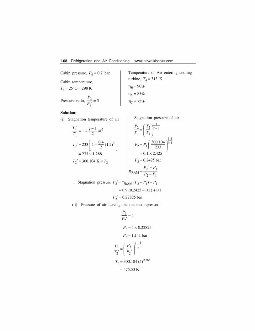
Cabin pressure, P6 0.7 bar
Cabin temperature,
T6 25C 298 K
Pressure ratio, P3
P2 5
Solution:
(i) Stagnation temperature of air
T2T1
1 1
2 M2
T2 233 1
0.42
1.22
233 1.288
T2 300.104 K T2
Stagnation pressure P2 RAM P2 P1 P1
0.9 0.2425 0.1 0.1
P2 0.22825 bar
(ii) Pressure of air leaving the main compressor
P3
P2 5
P3 5 0.22825
P3 1.141 bar
T3
T2 P3
P2
1
T3 300.104 50.286
475.53 K
Temperature of Air entering cooling
turbine, T4 313 K
R 90%
C 85%
T 75%
Stagnation pressure of air
P2
P1 T2
T1
1
P2 P1 300.104
233
1.40.4
0.1 2.425
P2 0.2425 bar
RAM P2 P1
P2 P1
1.68 Refrigeration and Air Conditioning - www.airwalkbooks.com

The temperature of air leaving the
compressor,
T3 T3 T2
c T2
475.53 300.104
0.85 300.104
206.34 300.104
T3 506.444 K
T5 T4 T T4 T5
313 0.75 313 277.6
T5 286.45 K
T5
T4 P5
P4
1
T5 313
0.751.141
0.4/1.4
313 0.887
T5 277.6 K
T
S
P 2
P 2’
P cabin
P = Am bien t 1
4
5
6
5 ’
3 ’3
2 ’2
1
Reversed Carnot Cycle and Air Refrigeration 1.69

Mass flow rate for 10 tons of
refrigeration TR
m
TR 210
Cp Tcockpit T5
10 210
1 298 286.45
m 181.82 kg/min
(iv) Volume handled by compressor
Vc m RT2
P2
181.82 287 300.104
0.22825 105
Vc 686.1 m3/min
(v) Net power required
Wnet m Cp T3 T2
181.82 1 506.44 300.104 37,500 kJ/min 37500
60 kW
Net power 625 kW
(vi) COP
COP m Cp Tcockpit T5m Cp T3 T2
298 286.45
506.44 300.104
COP 0.056
(vii) Power required for pressurization (excluding ram work)
Wpres m Cp T2c
Pcabin
P2
1 1
181.32 1 300.104
0.85
0.70.22825
0.286 1
(iii) Ram air heat exchanger
effectiveness
E T3 T4
T3 T2
506.444 313
506.444 300.104
E 0.937
Volume handled by cooling turbine
VT m RT4
P4
181.82 287 313
1.141 105
VT 143.15 m3/min
1.70 Refrigeration and Air Conditioning - www.airwalkbooks.com
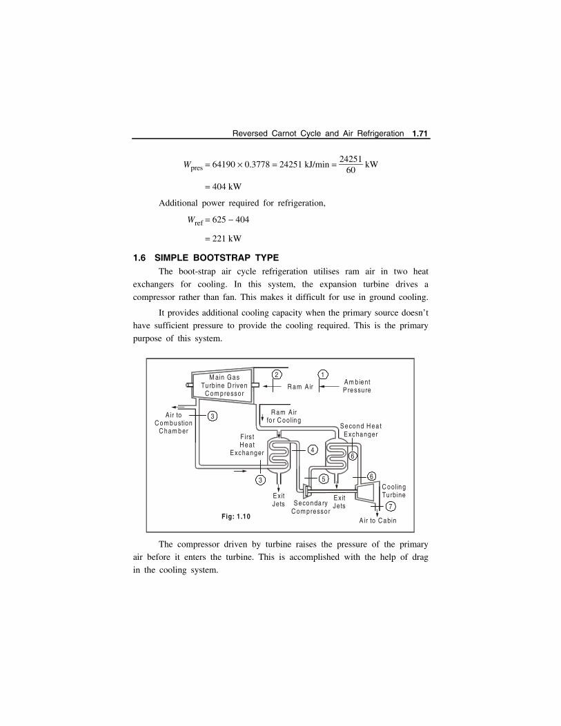
Wpres 64190 0.3778 24251 kJ/min 24251
60 kW
404 kW
Additional power required for refrigeration,
Wref 625 404
221 kW
1.6 SIMPLE BOOTSTRAP TYPEThe boot-strap air cycle refrigeration utilises ram air in two heat
exchangers for cooling. In this system, the expansion turbine drives a
compressor rather than fan. This makes it difficult for use in ground cooling.
It provides additional cooling capacity when the primary source doesn’t
have sufficient pressure to provide the cooling required. This is the primary
purpose of this system.
The compressor driven by turbine raises the pressure of the primary
air before it enters the turbine. This is accomplished with the help of drag
in the cooling system.
Air to C om bu stion
C ham b er
Ex it Jets Seconda ry
C om pressor A ir to C abin
C ooling Tu rbine
Second H ea tExchanger F irs t
H eat Exchanger
R am A ir fo r C ooling
R am A ir
Ex it Jets
M ain Gas Turbine D riven
C om pressor
Am b ient P ressu re
2 1
3
3
4
5
6
6
7Fig: 1.10
Reversed Carnot Cycle and Air Refrigeration 1.71
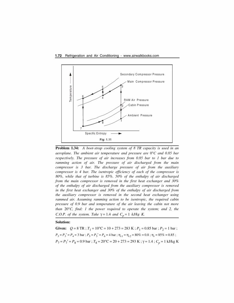
Problem 1.34: A boot-strap cooling system of 8 TR capacity is used in anaeroplane. The ambient air temperature and pressure are 0C and 0.85 barrespectively. The pressure of air increases from 0.85 bar to 1 bar due toramming action of air. The pressure of air discharged from the maincompressor is 3 bar. The discharge pressure of air from the auxiliarycompressor is 4 bar. The isentropic efficiency of each of the compressor is80%, while that of turbine is 85%. 50% of the enthalpy of air dischargedfrom the main compressor is removed in the first heat exchanger and 30%of the enthalpy of air discharged from the auxiliary compressor is removedin the first heat exchanger and 30% of the enthalpy of air discharged fromthe auxiliary compressor is removed in the second heat exchanger usingrammed air. Assuming ramming action to be isentropic, the required cabinpressure of 0.9 bar and temperature of the air leaving the cabin not morethan 20C, find: 1 the power required to operate the system; and 2, the
C.O.P. of the system. Take 1.4 and Cp 1 kJ/kg K.
Solution:
Given: Q 8 TR ; T1 10C 10 273 283 K ; P1 0.85 bar ; P2 1 bar ;
P3 P3 P4 3 bar ; P5 P5 P6 4 bar ; c1 c2 80% 0.8 ; r 85% 0.85 ;
P7 P7 P8 0.9 bar ; T8 20C 20 273 293 K ; 1.4 ; Cp 1 kJ/kg K
Fig: 1.11
6
5
4
8
7
2
1
3
Secondary C om pressor P ressure
M ain C om pressor P ressu re
C abin P ressure
R AM A ir Pressure
Am b ient P ressu re
Specific En tropy
Tem
pera
ture
1.72 Refrigeration and Air Conditioning - www.airwalkbooks.com

The temperature-entropy T s diagram with the given conditions is
shown in Fig.
For isentropic ramming process-2,
T2
T1 P2
P1
1
10.85
1.4 11.4
1.047
T2 T1 1.047 283 1.047 296.3 K
For isentropic process 2-3,
T3
T2 P3
P2
1
31
1.4 11.4
1.37
T3 T2 1.37 296.3 1.37 405.6 K
Isentropic efficiency of the compressor,
c1 Isentropic increase in temperature
Actual increase in temperature
T3 T2
T3 T2
18
2
7
7 ’
4
6
3
5
5 ’
1 bar
0.9 bar
0.85 bar
3 ’
3 bar4 b
ar
T 2
T =T1 8
T7 ’
T7
T 4
T 6
T 5
T 5 ’
T 3
T 3 ’
En tropy
Tem
pera
ture
Fig: (a)
Reversed Carnot Cycle and Air Refrigeration 1.73
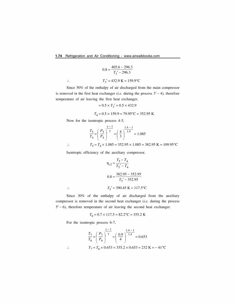
0.8 405.6 296.3
T3 296.3
T3 432.9 K 159.9C
Since 50% of the enthalpy of air discharged from the main compressor
is removed in the first heat exchanger (i.e. during the process 3 4), therefore
temperature of air leaving the first heat exchanger,
0.5 T3 0.5 432.9
T4 0.5 159.9 79.95C 352.95 K
Now for the isentropic process 4-5,
T5
T4 P5
P4
1
43
1.4 11.4
1.085
T5 T4 1.085 352.95 1.085 382.95 K 109.95C
Isentropic efficiency of the auxiliary compressor.
c2 T5 T4
T5 T4
0.8 382.95 352.95
T5 352.95
T5 390.45 K 117.5C
Since 30% of the enthalpy of air discharged from the auxiliary
compressor is removed in the second heat exchanger (i.e. during the process
5 6), therefore temperature of air leaving the second heat exchanger.
T6 0.7 117.5 82.2C 355.2 K
For the isentropic process 6-7,
T7
T6 P7
P6
1
0.94
1.4 11.4
0.653
T7 T6 0.653 355.2 0.653 232 K 41C
1.74 Refrigeration and Air Conditioning - www.airwalkbooks.com
Turbine efficiency,
r Actual increase in temperature
Isentropic increase in temperature
T6 T7T6 T7
0.85 361.3 T73613 236
361.3 T7
125.3
355.2 T7355.2 232
T7 250.5 K 22.5C
1. Power required to operate the system
Amount of air required for cooling the cabin.
m
a 210 TR
Cp T8 T7
210 8
1 293 250.5 39.53 kg/min
and power required to operate the system,
P ma Cp T3 T2
60
39.53 432.9 296.360
89.99 kW
2. C.O.P. of the system
COP 210 TR
ma Cp T3 T2
210 8
39.53 432.9 296.3 0.311
Problem 1.35: A boot-strap air refrigeration system is used for an air-planeto take 25 tons of cooling load. The ambient conditions are 7C and 0.9 bar.The air pressure increases to 1.3 bar due to ramming action which isconsidered ideal. The pressure of air bled off the main compressor is 4 bar.This air is further compressed in the secondary compressor to 4.8 bar. Theisentropic or internal efficiency of the main compressor as well as secondarycompressor is 90% and that of the cooling turbine is 80%. Heat exchangereffectiveness of the primary heat exchanger is 0.6 & that of secondary heatexchanger is 0.6. Assume Cp 1 kJ/kgK. Determine: (a) Power required to
take the cabin load. (b) COP of the system. The cabin may be maintained at 1 bar and 25C. The cooling turbine runsthe secondary compressor and uses its surplus power to drive fan.
Reversed Carnot Cycle and Air Refrigeration 1.75
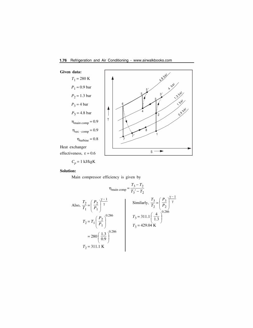
Given data:
T1 280 K
P1 0.9 bar
P2 1.3 bar
P3 4 bar
P5 4.8 bar
main comp 0.9
sec comp 0.9
turbine 0.8
Heat exchanger
effectiveness, 0.6
Cp 1 kJ/kgK
Solution:
Main compressor efficiency is given by
main comp T3 T2
T3 T2
Also, T2
T1 P2
P1
1
T2 T1 P2
P1
0.286
280 1.30.9
0.286
T2 311.1 K
Similarly, T3
T2 P3
P2
1
T3 311.1
41.3
0.286
T3 429.04 K
T
S
6
77’
3 ’3
5
24
81
5 ’
4.8 bar
4 bar
1.3 bar
1 b ar
0.9 b
ar
1.76 Refrigeration and Air Conditioning - www.airwalkbooks.com
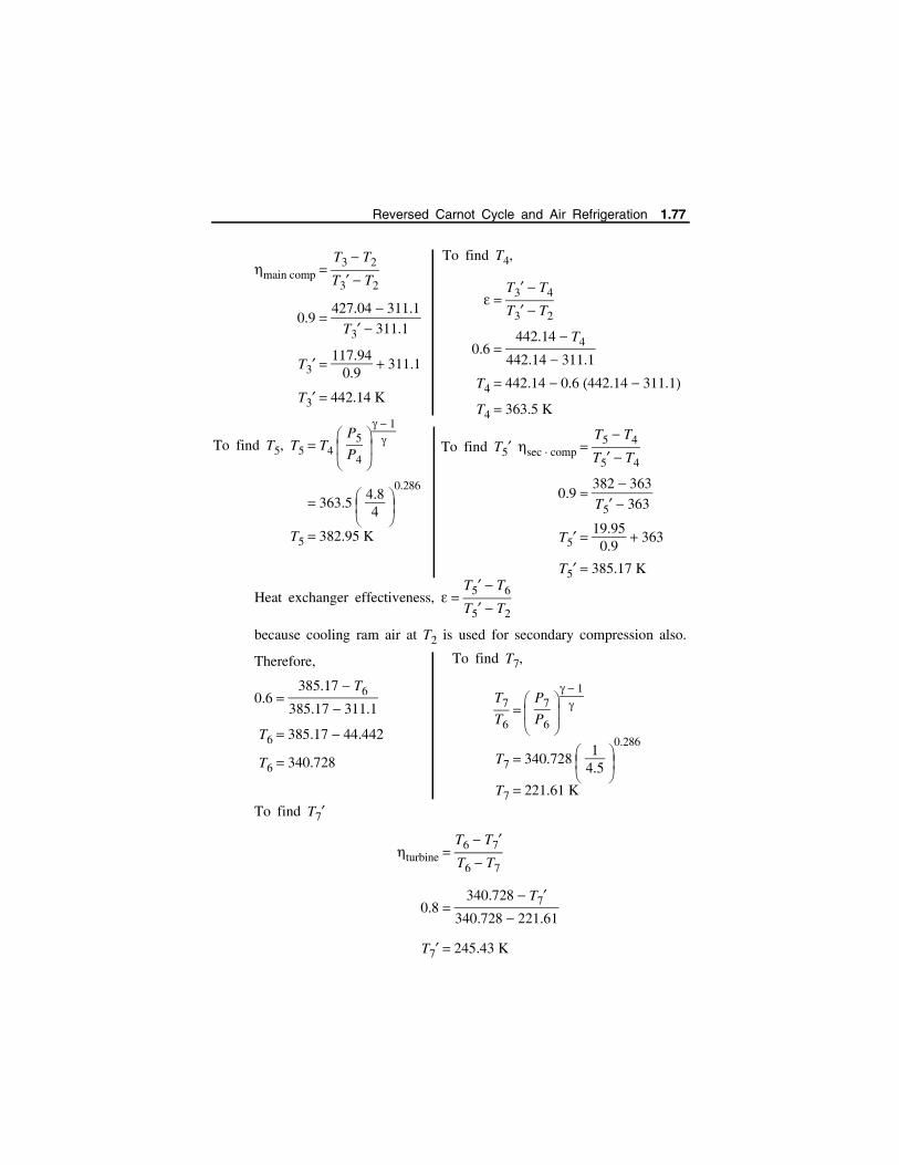
main comp T3 T2
T3 T2
0.9 427.04 311.1
T3 311.1
T3 117.94
0.9 311.1
T3 442.14 K
To find T5, T5 T4 P5
P4
1
363.5 4.84
0.286
T5 382.95 K
Heat exchanger effectiveness, T5 T6
T5 T2
because cooling ram air at T2 is used for secondary compression also.
Therefore,
0.6 385.17 T6
385.17 311.1
T6 385.17 44.442
T6 340.728
To find T7
turbine T6 T7T6 T7
0.8 340.728 T7
340.728 221.61
T7 245.43 K
To find T4,
T3 T4
T3 T2
0.6 442.14 T4
442.14 311.1
T4 442.14 0.6 442.14 311.1
T4 363.5 K
To find T5 sec comp T5 T4
T5 T4
0.9 382 363
T5 363
T5 19.95
0.9 363
T5 385.17 K
To find T7,
T7
T6 P7
P6
1
T7 340.728
14.5
0.286
T7 221.61 K
Reversed Carnot Cycle and Air Refrigeration 1.77

Thus, cooling turbine discharge temperature 239.36 273
33.64CMass flow rate through cabin for 25 ton load,
m
TR 210
Cp Tcabin Tt
25 210
1 25 33.64
420058.64
1 TR 210
kJmin
m 71.6 kg/min
Power required for refrigeration load
m Cp T3 T2
60
71.6 1 442.14 311.1
60
156.37 kW
1.7 REGENERATIVE SYSTEM
COP of the system
TR 210
Workdone
25 210
156.37 60
COP of the system
0.5596
[ . . . 210 is multiplied to convert
tonnage into kJ/min]
Fig : 1.12 Regenerative System
8
5
C oo ling Tu rb ine
R egene ra tive (S econda ry) H ea t
Exchanger
To C abin
To A tm osphe re
Jet
Com
pres
sor
2 ’
C oo ling A ir
4
A irC oo le r
3 ’
C om pressed A ir
C oo ling A ir F an
C oo ling A ir E x it
R am A ir
H ea t Exchanger
6 ’ 6 ’
6 ’
1Am b ien t
A ir
m 1
m 2
1.78 Refrigeration and Air Conditioning - www.airwalkbooks.com
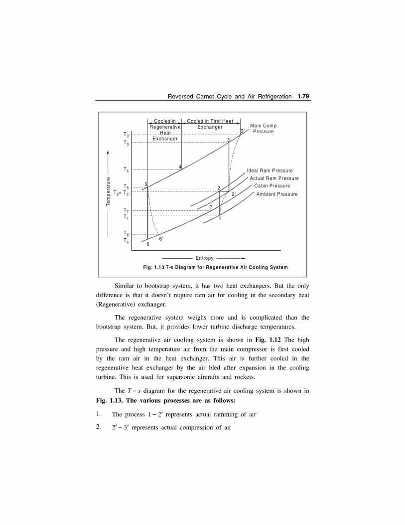
Similar to bootstrap system, it has two heat exchangers. But the only
difference is that it doesn’t require ram air for cooling in the secondary heat
(Regenerative) exchanger.
The regenerative system weighs more and is complicated than the
bootstrap system. But, it provides lower turbine discharge temperatures.
The regenerative air cooling system is shown in Fig. 1.12 The high
pressure and high temperature air from the main compressor is first cooled
by the ram air in the heat exchanger. This air is further cooled in the
regenerative heat exchanger by the air bled after expansion in the cooling
turbine. This is used for supersonic aircrafts and rockets.
The T s diagram for the regenerative air cooling system is shown in
Fig. 1.13. The various processes are as follows:
1. The process 1 2 represents actual ramming of air
2. 2 3 represents actual compression of air
Ideal Ram Pressure
Actual Ram Pressure
Cabin P ressure
Am bien t Pressure
M ain Com pPressure
3
3 ’
22 ’
7
1
66 ’
5
4
Entropy
Tem
per
atur
e
T3 ’
T3
T4
T5
T7T1
T6
T6 ’
T = T2 2 ’
Fig: 1.13 T-s Diagram for Regenerative Air Cooling System
Cooled in Regenerative
HeatExchanger
Cooled in Firs t Heat Exchanger
Reversed Carnot Cycle and Air Refrigeration 1.79

3. The process 3 4 represents cooling of compressed air by ram air in
the first heat exchanger.
4. The process 4 5 represents cooling of air in the regenerative heat
exchanger.
5. The process 5 6 represents actual expansion of air in the cooling
turbine.
6. The process 6 7 represents heating of air upto the cabin temperature
T7.
If the TR ton of refrigeration is the cooling load in the cabin, then
the quantity of air required
m
a 210 TR
Cp T7 T6 kg/min m
1 m
2
where m
1 Total mass of air bled from the main compressor, and
m
2 Mass of cold air bled from the cooling turbine for regenerative
heat exchanger.
For the energy balance of regenerative heat exchanger, we have
m
2 Cp T8 T6 m
1 Cp T4 T5
m
2 m
1 T4 T5T8 T6
where T8 Temperature of air leaving to atmosphere from the regenerative
heat exchanger.
Power required for the refrigeration system,
P m
1 Cp T3 T260
kW
and C.O.P. of the refrigerating system
210 TR
m
1 Cp T3 T2
210 TR
P 600
1.80 Refrigeration and Air Conditioning - www.airwalkbooks.com

Problem 1.36: A regenerative are cooling system is used for an air planeto take 26 tonnes of refrigeration load. The ambient air at pressure 0.8 barand temperature 8C is rammed isentropically till the pressure rises to 1.2bar. The air bled off the main compressor at 4.5 bar is cooled by the ramair in the heat exchanger whose effectiveness is 70%. The air from the heatexchanger is further cooled to 60C in the regenerative heat exchanger witha portion of the air bled after expansion in the cooling turbine. The cabinis to be maintained at a temperature of 25C and a pressure of 1 bar. Ifthe isentropic efficiencies of the compressor and turbine are 90% and 80%respectively. find:1. Mass of the air bled from cooling turbine to be used for regenerativecooling;2. Power required for maintaining the cabin at the required condition; and
3. C.O.P of the system. Assume the temperature of air leaving to atmosphere from the regenerativeheat exchanger as 80C and Cp 1 kJ/kg K
Solution:
Given: Q 26 TR ; P1 0.8 bar ; T1 8C 8 273 281 K ; P2 1.2 bar ;
P3 P4 P5 4.5 bar ; H 70% 0.7 ; T5 60C 60 273 333 K ;
T7 25C 25 273 298 K ; P7 P6 P6 1 bar ; c 0.9 ; T 80% 0.8;
T8 80C 80 273 353 K
The T s diagram for the regenerative air cooling system with the
given conditions is shown in Fig.
T2 Temperature of air at the end of ramming and entering to the maincompressor.
T3 Temperature of air after isentropic compression
T3 Actual temperature of air leaving the main compressor.
For the isentropic ramming of air (process 1-2),
Reversed Carnot Cycle and Air Refrigeration 1.81

T2
T1 P2
P1
1
1.20.8
1.4 11.4
1.123
T2 T1 1.123 281 1.123 315.6 K
and for the isentropic compression process 2-3,
T3
T2 P3
P2
1
4.51.2
1.4 11.4
1.46
T3 T2 1.46 315.6 1.46 460.4 K
Isentropic efficiency of the compressor,
c Isentropic increase in temperature
Actual increase in temperature
T3 T2
T3 T2
0.9 460.4 315.6
T3 315.6
T3 476.5 K
T3 ’
T3
T4
T5
T2
T7T1
T6
T 6 ’ 6 ’6
1
7
5
4
2
3
3’
1.2 ba r
1 bar
0.8 ba r
4.5 ba r
Entropy
Tem
pera
ture
Fig
1.82 Refrigeration and Air Conditioning - www.airwalkbooks.com

We know that effectiveness of the heat exchanger H,
0.7 T3 T4
T3 T2
476.5 T4
476.5 315.6
T4 363.9 K
Now for the isentropic expansion in the cooling turbine (process 5-6),
T5
T6 P5
P6
1
4.51
1.4 11.4
1.54
T6 216 K
and isentropic efficiency of the cooling turbine,
T Actual drop in temperature
Isentropic drop in temperature
T5 T6T5 T6
0.8 333 T6333 216
333 T6
117
T6 333 0.8 117 239.4 K
1. Mass of air bled from the cooling turbine to be used for regenerativecooling
Let m
a Mass of air from the cooling turbine to cabin m
1 m
2
m
1 Total mass of air bled from the main compressor, and
m
2 Mass of cold air bled from the cooling turbine for regenerative
heat exchanger.
We know that the mass of air supplied to the cabin.
m
a m
1 m
2
210 TR
Cp T7 T6
210 20
1 298 239.4 71.7 kg/min
(i)
and m
2 m
1 T4 T5T8 T6
m
1 363.9 333353 239.4
0.272 m1(ii)
Reversed Carnot Cycle and Air Refrigeration 1.83

From equation (i), we find that
m1 m2 71.7 or m1 0.272 m1 71.7
m1 71.7
1 0.272 98.5 kg/min
and m2 0.272 m1 0.272 98.5 26.8 kg/min
Note: Since m2/m1 0.272, the air bled from the cooling turbine for
regenerative cooling is 27.2% of the total air bled from the main compressor.
2. Power required for maintaining the cabin at the required condition
P m
1 Cp T3 T260
98.5 1 476.5 315.6
60 264.1 kW
3. C.O.P. of the system
C.O.P. 210 TR
m
1 Cp T3 T2
210 26
98.5 1 476.5 315.6 0.345
1.8 REDUCED AMBIENT SYSTEMThis system contains two expansion turbines-one for cabin air stream
and the other for cooling air stream in heat exchanger (air cooler). Both
turbines are connected to the shaft driving fan which absorbs all the power.
Jet
Co
mp
ress
or
R am A ir
R am A ir 1
A ir C ooler
4
C om presse d A ir
To C ab in 6
C ooling Tu rb ine for C ab in
C ooling A ir Fan
R eduction G earC ooling Tu rb ine
fo r Co m pressedR am A ir
Fig: 1.14 Reduced Ambient System
2 ’
1
(H eat Exchanger)
befo re C om press ion
Am b ient A ir
3 ’ 3 ’
5 ’
1.84 Refrigeration and Air Conditioning - www.airwalkbooks.com
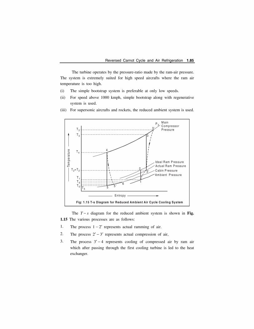
The turbine operates by the pressure-ratio made by the ram-air pressure.
The system is extremely suited for high speed aircrafts where the ram air
temperature is too high.
(i) The simple bootstrap system is preferable at only low speeds.
(ii) For speed above 1000 kmph, simple bootstrap along with regenerative
system is used.
(iii) For supersonic aircrafts and rockets, the reduced ambient system is used.
The T s diagram for the reduced ambient system is shown in Fig.
1.15 The various processes are as follows:
1. The process 1 2 represents actual ramming of air.
2. The process 2 3 represents actual compression of air,
3. The process 3 4 represents cooling of compressed air by ram air
which after passing through the first cooling turbine is led to the heat
exchanger.
3
3 ’P 3
M ain C om pressor P ressu re
Idea l R am P ressure
T44
T3
T3 ’
1
22 ’
5 5 ’6
Entropy
Tem
pera
ture
T = T2 2 ’
T 1T 6T5 ’ T5
Actual R am Pre ssure C abin P ressure Am b ient P ressu re
Fig: 1.15 T-s Diagram for Reduced Am bient Air Cycle Cooling System
Reversed Carnot Cycle and Air Refrigeration 1.85
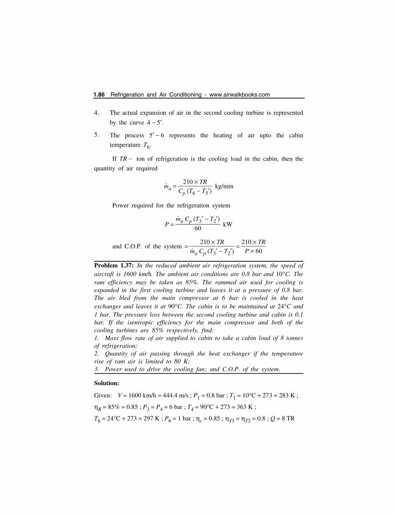
4. The actual expansion of air in the second cooling turbine is represented
by the curve 4 5.
5. The process 5 6 represents the heating of air upto the cabin
temperature T6.
If TR ton of refrigeration is the cooling load in the cabin, then the
quantity of air required
m
a 210 TR
Cp T6 T5 kg/min
Power required for the refrigeration system
P m
a Cp T3 T260
kW
and C.O.P. of the system 210 TR
m
a Cp T3 T2
210 TR
P 60
Problem 1.37: In the reduced ambient air refrigeration system, the speed ofaircraft is 1600 km/h. The ambient air conditions are 0.8 bar and 10C. Theram efficiency may be taken as 85%. The rammed air used for cooling isexpanded in the first cooling turbine and leaves it at a pressure of 0.8 bar.The air bled from the main compressor at 6 bar is cooled in the heatexchanger and leaves it at 90C. The cabin is to be maintained at 24C and1 bar. The pressure loss between the second cooling turbine and cabin is 0.1bar. If the isentropic efficiency for the main compressor and both of thecooling turbines are 85% respectively, find: 1. Mass flow rate of air supplied to cabin to take a cabin load of 8 tonnesof refrigeration; 2. Quantity of air passing through the heat exchanger if the temperaturerise of ram air is limited to 80 K; 3. Power used to drive the cooling fan; and C.O.P. of the system.
Solution:
Given: V 1600 km/h 444.4 m/s ; P1 0.8 bar ; T1 10C 273 283 K ;
R 85% 0.85 ; P3 P4 6 bar ; T4 90C 273 363 K ;
T6 24C 273 297 K ; P6 1 bar ; c 0.85 ; T1 T2 0.8 ; Q 8 TR
1.86 Refrigeration and Air Conditioning - www.airwalkbooks.com
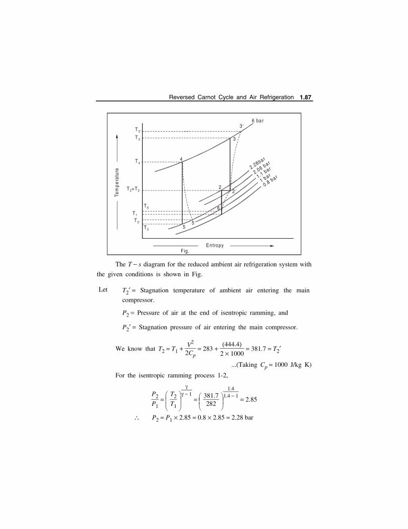
The T s diagram for the reduced ambient air refrigeration system with
the given conditions is shown in Fig.
Let T2 Stagnation temperature of ambient air entering the main
compressor.
P2 Pressure of air at the end of isentropic ramming, and
P2 Stagnation pressure of air entering the main compressor.
We know that T2 T1 V2
2Cp 283
444.42 1000
381.7 T2
...(Taking Cp 1000 J/kg K)
For the isentropic ramming process 1-2,
P2
P1 T2
T1
1
381.7282
1.41.4 1
2.85
P2 P1 2.85 0.8 2.85 2.28 bar
4
2
55 ’
2 ’
6
3
3 ’6 ba r
T 4
T 3
T 3 ’
T 6
T 5
T 5 ’
T1
T =T2 2 ’
0 .8 bar1 bar1 .1 bar
2 .06 ba r2.28ba r
En tropy
Tem
pe
ratu
re
F ig.
Reversed Carnot Cycle and Air Refrigeration 1.87

We know that ram efficiency,
R Actual rise in pressure
Isentropic rise in pressure
P2 P1
P2 P1
0.85 P2 0.8
2.28 0.8
P2 2.06 bar
The T s diagram for the expansion of ram air in the first cooling
turbine is shown in Fig. The vertical line 2 1 represents the isentropic
cooling process and the curve 2 2 represents the actual cooling process.
Now for the isentropic cooling process 2 1.
T2T1
P2P1
1
2.060.8
1.4 1
1.4 1.31[T2 T2]
Entropy
Tem
pera
ture
2 2 ’
2 ’’
1
1 ’
T2 ’’
T1 ’
T1
T = T2 2 ’
0 .8 ba r
2 .06 bar2 .28 bar
Fig: T-s Diagram for the F irst Cooling Turbine
1.88 Refrigeration and Air Conditioning - www.airwalkbooks.com
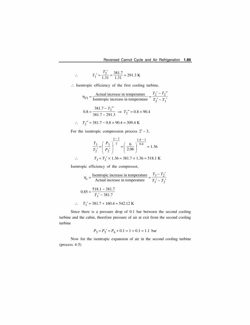
T1 T2
1.31
381.71.31
291.3 K
Isentropic efficiency of the first cooling turbine,
T1 Actual increase in temperature
Isentropic increase in temperature
T2 T2T2 T1
0.8 381.7 T2
381.7 291.3 T2 0.8 90.4
T2 381.7 0.8 90.4 309.4 K
For the isentropic compression process 2 3,
T3
T2 P3
P2
1
62.06
1.4 10.4
1.36
T3 T2 1.36 381.7 1.36 518.1 K
Isentropic efficiency of the compressor,
c Isentropic increase in temperature
Actual increase in temperature
T3 T2T3 T2
0.85 518.1 381.7
T3 381.7
T3 381.7 160.4 542.12 K
Since there is a pressure drop of 0.1 bar between the second cooling
turbine and the cabin, therefore pressure of air at exit from the second cooling
turbine
P5 P5 P6 0.1 1 0.1 1.1 bar
Now for the isentropic expansion of air in the second cooling turbine
(process 4-5)
Reversed Carnot Cycle and Air Refrigeration 1.89
T4
T5 P4
P5
1
61.1
1.4 11.4
1.62
T5 T4
1.62
3631.62
224 K
The isentropic efficiency of the second cooling turbine,
T2 Actual increase in temperature
Isentropic increase in temperature ‘
T4 T5T4 T5
0.8 363 T5363 224
;
T5 363 111.2 251.8K
1. Mass flow rate of air supplied to cabin,
m
a 210 TR
Cp T6 T5
210 8
1 297 251.8 37.17 kg/min
2. Quantity of ram air passing through the heat exchanger
m
R Quantity of ram air passing through the heat exchanger.
The compressed air bled off at temperature T3 542.12 K is cooled
in the heat exchanger to a temperature T4 363 K by the ram air from the
first cooling turbine at a temperature T2 309.4 K. The temperature rise of
ram air in the heat exchanger is limited to 80 K. Considering perfect heat
transfer in the heat exchanger.
m
R Cp 80 m
a Cp T3 T4
m
R 1 80 37.17 1 542.12 363 6658
m
R 6658
80 83.2 kg/min
1.90 Refrigeration and Air Conditioning - www.airwalkbooks.com
3. Power used to drive the cooling fan
Since the works output of both the cooling turbines are used to drive
the cooling fan, work output from the first cooling turbine,
WT1 m
R Cp T2 T2
83.2 1 381.7 309.4 6017 kJ/min
and work output from the second cooling turbine,
WT2 m
a Cp T4 T5 37.17 1 363 251.8 4133.3 kJ/min
Combined work output from both the cooling turbines.
WT WT1 WT2 6017 4133.3 1883.7 kJ/min
and power used to drive the cooling fan
1883.7
60 31.4 kW
4. C.O.P. of the system
We know that C.O.P. of the system
210 TR
m
a Cp T3 T2
210 8
37.17 542.12 381.7 0.282
Reversed Carnot Cycle and Air Refrigeration 1.91
INDEX
A
Alloy steels, 1.11
Application of power screw, 3.39
Applications of the springs, 5.2
B
Bolt of uniform strength, 3.6
Bolted joints, 3.17
Buckling of compression springs, 5.11
Bushed pin flexible coupling, 6.117
Butt joint in tension, 4.153
C
Cast iron, 1.9
Cast steel, 1.11
Caulking and fullering, 4.6
Causes of failure in shafts, 6.3
Classification of couplings, 6.97
Classification of design, 1.3
Classification of welding, 4.119
Close-coiled helical spring, 5.6
Coaxial springs, 5.89
Common types of screw fastening, 3.4
Common modes of failure, 2.1
Compression stress, 3.19
Concentric springs, 5.87
Conical and volute springs, 5.96
Cotter joints, 4.84
Critical frequency, 5.14
Cumulative fatigue damage, 2.57
Curvature effect, 5.9
D
Design of shaft based on strength, 6.4
Design of gib and cotter joint, 4.113
Design procedure of key, 6.93
Design of screw jack, 3.74
Design of structural joints, 4.10
Design of circumferential joint, 4.71
Design of structural joints, 4.64
Design stresses, 4.63
Design of sleeve and cotter joint, 4.106
Design of flexible couplings, 6.116
Design of bolts for cylinder cover, 3.8
Design of rigid coupling, 6.98
Design of power screws, 3.39
Design for finite life, 2.56
Design based on critical speed, 6.12
Direct tensile stress, 3.18
Disc springs (or) belleville springs, 5.81
Ductile fracture, 1.26
E
Eccentric loading of springs, 5.11
Effect of initial tension, 3.17
Effects of keyways, 6.93
Index I.1

Efficiency of a Riveted Joint, 4.64
End connections for helical springs, 5.10
Endurance limit stress, 2.43
F
Factor of safety, 1.30, 2.2
Factors influencing machine design, 1.4
Factors affecting endurance limit, 2.45
Failures modes of keys, 6.90
Fatigue loading of helical springs, 5.65
Fatigue failure, 2.39
Features of shaft coupling, 6.97
Ferrous metals, 1.9
Flange coupling, 6.111
Flat spiral spring, 5.78
Forces acting on a key, 6.89
Friction in V-threads (ACME thread), 3.49
Friction in power screw, 3.41
G
Gasketed joint, 3.32
Gaskets, 3.31
H
Helical springs, 5.5
Helical torsion spring, 5.71
I
Impact stress, 1.35
Initial gap, 5.104
Initial pre-load, 5.105
K
Knuckle joint, 4.79
L
Leaf spring material, 5.108
Leaf spring, 5.97
M
Material for Rivets, 4.2
Mechanical properties of materials, 1.6
Mechanism of ductile fracture, 1.27
Modes of failures in riveted joint, 4.7
N
Nipping of leaf springs, 5.103
Non-ferrous metals, 1.14
O
Oldham Coupling, 6.160
Open-coiled helical spring, 5.6
P
Permissible stresses, 5.108
Plastic behaviour of metals, 1.26
Preferred numbers, 1.15
Principal stresses, 1.37
R
Resilience, 5.13
Riveted joints, 4.1
I.2 Design of Machine Elements – I - www.airwalkbooks.com

S
Selection of materials, 1.8
Shafting materials, 6.3
Shear stress in the threads, 3.19
Shock and impact loads, 2.40
Simple stresses, 1.19
Sleeve and cotter joint, 4.106
Soderberg and Goodman diagrams, 2.47
Spring materials, 5.1
Springs in series, 5.69
Springs in parallel, 5.70
Springs, 5.1
Standard shaft diameters, 6.2
Standards and codes, 1.17
Static loading, 5.13
Steel, 1.10
Stiffness (k), 6.9
Strength of a Riveted Joint, 4.64
Stress in shafts, 6.3
Stress concentration, 1.72
Stresses in power screws, 3.54
Stresses in butt weld, 4.152
System of designation for steels, 1.12
T
Theories of failure, 2.3
Threaded joints, 3.1
Torque diagrams, 6.14
Torsional shear stress, 3.18
Types of ends for extension springs, 5.12
Types of welded joints, 4.119
Types of riveted joints, 4.4
Types of power screw threads, 3.40
Types of shaft (according to use), 6.2
U
Universal or Hooke’s coupling, 6.160
Welded joints, 4.118
*********
Index I.3