REFINING THE UNIVERSITY OF IDAHO CLEAN SNOWMOBILE · refining the university of idaho clean...
27
REFINING THE UNIVERSITY OF IDAHO CLEAN SNOWMOBILE FINAL REPORT NOVEMBER 2002 Report Budget Number KLK304 NIATT Report #N02-08 Prepared for OFFICE OF UNIVERSITY RESEARCH AND EDUCATION U.S. DEPARTMENT OF TRANSPORTATION Prepared by NATIONAL INSTITUTE FOR ADVANCED TRANSPORTATION TECHNOLOGY UNIVERSITY OF IDAHO Phil Auth, Mark Chin, Patrick Hess, and Karen Den Braven
Transcript of REFINING THE UNIVERSITY OF IDAHO CLEAN SNOWMOBILE · refining the university of idaho clean...

REFINING THE UNIVERSITY OF IDAHO
CLEAN SNOWMOBILE
FINAL REPORT NOVEMBER 2002
Report Budget Number KLK304
NIATT Report #N02-08
Prepared for
OFFICE OF UNIVERSITY RESEARCH AND EDUCATION U.S. DEPARTMENT OF TRANSPORTATION
Prepared by
NATIONAL INSTITUTE FOR ADVANCED TRANSPORTATION TECHNOLOGY UNIVERSITY OF IDAHO
Phil Auth, Mark Chin, Patrick Hess,
and Karen Den Braven

TABLE OF CONTENTS
EXECUTIVE SUMMARY ...................................................................................................... 1
DESCRIPTION OF PROBLEM............................................................................................... 2
Approach and methodology.....................................................Error! Bookmark not defined.
DESIGN GOALS.................................................................................................................. 3
ACKNOWLEDGEMENTS.................................................................................................... 25
REFERENCES ....................................................................................................................... 25
Refining the University of Idaho Clean Snowmobile i

EXECUTIVE SUMMARY
The 2001 SAE Clean Snowmobile Challenge entry for the University of Idaho (UI) provided
proof-of-concept for a clean snowmobile using a four-stroke engine, exhaust after treatment,
and electronic fuel injection. This combination provided excellent emissions and fuel
consumption performance while maintaining acceptable power and nearly acceptable noise
production. The 2002 entry built on this design while focusing on improving the overall
efficiency of the snowmobile. The BMW engine was tuned for high altitude operation, higher
efficiency components reduced chassis losses, and additional sound damping was utilized
throughout the chassis.
Refining the University of Idaho Clean Snowmobile 1

DESCRIPTION OF PROBLEM The Clean Snowmobile Challenge (CSC) is a Society of Automotive Engineers (SAE)
student design competition, which was first held in March 2000. The competition was
designed to give students throughout the US and Canada the opportunity to further
snowmobile technology while gaining valuable design experience. Conventional
snowmobiles are powered using two-stroke engines. The two-stroke engine is loud,
sometimes in excess of 102 dBA at a distance of 15 m (50 ft) [1], and releases substantially
more unburned hydrocarbons and other pollutants than would be released by a comparably
powered automobile. The goals of the snowmobile competition focus on reducing these
undesirable characteristics of snowmobiles.
Refining the University of Idaho Clean Snowmobile 2

APPROACH AND METHODOLOGY
DESIGN GOALS
To refine the UI Clean Snowmobile, several design changes were initiated to reduce exhaust
gas and sound emissions while increasing fuel economy and maintaining performance. The
first goal was to reduce carbon monoxide and unburned hydrocarbon emissions by at least 50
percent when compared to a standard consumer model two-stroke touring snowmobile.
Reducing noise from a snowmobile is also a large priority for the competition. The rules
required that snowmobiles produced a sound intensity no greater than 74 dB on the A scale
when measured on open ground from a distance of 15 m at a wide-open throttle.
The next goal was to improve fuel efficiency beyond that of conventional touring
snowmobiles. The target range for the competition snowmobile is 160 km (100 mi). Each
snowmobile must complete a 160 km route through Yellowstone National Park while
following a park guide pacing them at a moderate speed of 72 kilometers per hour (kph), (45
mph) [2]. This insured that fuel consumption for all snowmobiles was based on the same
duty cycle.
To quantify performance and handling characteristics, the student designed snowmobiles also
competed in acceleration, hill climb, and handling events. The acceleration event was based
on the time taken to travel 152 m (500 ft) starting from a complete stop. To pass this event,
the snowmobile must complete this course in less than 10.5 seconds. The hill climb event
took place on a set course up the side of Snow King Mountain in Jackson Hole, Wyoming,
during the World Hill Climb Championship. Scoring was assessed based on the time taken
for the snowmobile to complete the climb. In the event that a snowmobile did not finish the
climb, it was scored based on the maximum elevation reached. To assess handling, each of
the snow machines was ridden by at least five professional drivers around a closed circuit
course and subjectively ranked [2].
Refining the University of Idaho Clean Snowmobile 3

Students also submitted a technical design paper describing the approach taken and the
challenges met in designing and building their snowmobiles and completed an oral design
presentation. These presentations focus on how the teams’ snowmobiles accomplished the
goals of the competition. The snowmobiles are also subjected to a morning cold start, and
must start within 20 seconds without use of starting fluids. All of the student snowmobiles
were on display to the public during the course of the World Championship Hill Climb.
SNOWMOBILE CONCEPT
To meet these design challenges, the UI Clean Snowmobile Challenge team took proven
technologies from differing areas of transportation and combined them into their competition
snowmobile. A four-stroke engine, whose emission and efficiency characteristics already met
the competition guidelines, was placed into an aluminum, sport snowmobile chassis. The
already attractive qualities of the four-stroke engine were augmented by the addition of a fuel
injection system and a single stage exhaust catalyst.
TEAM ORGANIZATION
The 2002 University of Idaho Clean Snowmobile team consisted of nine undergraduate
mechanical engineering students, one undergraduate electrical engineering student, one
graduate student, and one faculty advisor. The team divided into six sub-groups assigned to
work on the different snowmobile systems.
2001 DESIGN SUMMARY
The UI Clean Snowmobile Challenge entry for the 2002 competition is based on the 2001
competition entry. The snowmobile entered in the previous competition performed very well.
It proved to be very durable, finishing every competition without any mechanical or electrical
failures. It also ranked high in the fuel consumption, handling, and emissions events. The
snowmobile had moderate power but missed the qualifying noise measurement by 0.3 dBA.
Given the performance and durability of the 2001 entry, it was elected to focus on improving
Refining the University of Idaho Clean Snowmobile 4

the deficits observed during that competition, while maintaining the same basic design
concepts. The following paragraphs summarize these design concepts. For a more complete
description, please see the 2001 design paper [3].
ENGINE SELECTION
Candidate engines were ranked based on exhaust gas emissions, noise emissions, fuel
economy, weight, cost, and ease of implementation. Four different types of engines were
compared. These engines were: conventional two-stroke, four-stroke, fuel-injected two-
stroke, and rotary. The engine selected was a 1991 BMW K75RT motorcycle engine. This
engine was chosen for several qualities. First, it is a four-stroke engine, which is inherently
more fuel efficient, less polluting, quieter, and more tolerant of exhaust after-treatment than
its two-stroke counterparts. The engine displacement is 740 cubic centimeters (cc) which is
large enough to produce acceptable power, but under the 960cc limit for entry into the
competition. Another desirable quality of this engine was that it could be unbolted from the
stock motorcycle transmission. This eliminated the need to cut off or use that transmission.
The engine was also chosen for its size. Its physical dimensions were such that it could be
mounted under the hood of the selected snowmobile chassis. The primary drawback of this
engine was its heavier-than-average weight.
Mounting the engine required a few modifications. A baseplate was mounted on the engine
in place of the stock oil pan, enabling the engine to be bolted to the chassis frame. The engine
output shaft was adapted to the primary clutch using an adapter shaft. A bearing carriage was
also designed to support the side loads exerted on the output shaft through the CVT clutches.
Figure 1 shows a photograph of the mounting plate, bearing carriage, and support foot as
installed on the snowmobile.
Refining the University of Idaho Clean Snowmobile 5

Figure 1 Bearing carriage, motor mounting plate, and support foot.
CHASSIS
The chassis selected for the 2001 competition was a 2001 Arctic Cat SnoPro chassis. It was
purchased as a rolling chassis. The lightweight aluminum frame helped to offset the
additional weight of the engine. The SnoPro chassis was designed as a racing chassis, and as
such has special suspension tuning options not available on a standard chassis. These tuning
options were also used to help compensate for the additional weight of the engine. The
bearing carriage, which houses the adapted output shaft from the engine, was mounted to the
engine using the bolt pattern from the bell housing.
TRANSMISSION
The transmission used for the 2001 competition snowmobile consisted of a standard
snowmobile continuously variable transmission (CVT) and chain case. The CVT was tuned
for use with the BMW engine. The base primary clutch settings for the competition
snowmobile consist of 48.5 gram non-notched cam arms, two 0.152 cm (0.060 in) shims
behind the spider, and a red Arctic Cat spring. The primary clutch was connected to a
standard Arctic Cat roller secondary clutch, utilizing a 49 degree helix and a blue spring in
Refining the University of Idaho Clean Snowmobile 6

the fourth hole location. A 0627-004 Arctic Cat belt running on the 27.3 cm (10.75 in)
center-to-center distance couples the two clutches.
EXHAUST
The 2001 exhaust system was designed to reduce emissions and engine noise. The exhaust
system was routed across the front of the engine compartment, where it could be cooled
using incoming air. The naturally lower emissions of the fuel injected four-stroke engine
were further reduced by a standard automotive single stage catalytic converter. The final
stage in the exhaust system was the stock BMW motorcycle muffler. In places where the
exhaust system passed by heat sensitive components an aircraft thermal radiation shielding
was used for protection.
FUEL SYSTEM
The fuel system used on the 2001 competition snowmobile was based on the stock BMW
multi-port Bosch fuel injection system. The only major modification to the system was the
selection of an external fuel pump instead of the stock in-tank pump. The fuel lines were
modified using ball valves and T-fittings to accommodate an external fuel tank for use in
dynamometer testing.
ELECTRICAL
The finished electrical system on the 2001 snowmobile was composed of both the
snowmobile chassis electrical system and the BMW motorcycle electrical system. The
chassis electrical system was made up primarily of wires routed to the lights, shutoff
switches, and hand warmers. The engine electrical system was made up of the engine
management and fuel injection systems. The chassis and engine systems were then adapted
together. This required the removal of all the non-essential systems from the motorcycle
electrical system and the addition of a special circuit to adapt the chassis engine shutoff
system to the motorcycle engine shutoff system.
Refining the University of Idaho Clean Snowmobile 7

SNOWMOBILE LAYOUT
To mount the four-stroke engine in the chassis, available space under the hood had to be
allocated very carefully. The BMW motor was designed to fit into a street motorcycle
chassis. Thus, the engine management components are designed to fit lengthwise along the
span of a motorcycle frame. However, a snowmobile chassis only allows for engine
component placement centrally under the hood and around the motor. Therefore, the
electrical and cooling systems had to be tightly woven within the confines of the bulkhead to
integrate the motor into the chassis. In the end, the majority of available room under the hood
and beneath the seat was occupied.
The cooling system was rerouted to the right side of the engine. Electrical components were
distributed between the area around steering post and fuel tank, and under the seat. The fuel
pump was mounted tightly between the tunnel floor and the snowmobile firewall, with the
remaining components of the fuel system in their original motorcycle configuration on the
top of the engine. Looking at the snowmobile engine compartment from the seat, the exhaust
system was routed outward towards the front left side of the engine compartment, bending to
the right across the front of the nose cone and exiting longitudinally along the right side of
the belly pan. The CVT is housed on the left side of the motor, and the belt drive system is
opposite the secondary clutch on the right side of the engine.
2002 SNOWMOBILE DESIGN
ENGINE MODIFICATIONS
The primary focus was to improve the performance of the 1991 BMW K75RT motorcycle
engine already incorporated into the design. The engine has a 740 cubic centimeter
displacement composed of three multi-port fuel injected cylinders. Several performance
enhancement options were evaluated, including turbocharging, aftermarket electronic fuel
injection kits, new ignition systems, and cylinder boring and or stroking to produce a larger
displacement. It was decided that no major modifications to the engine would be conducive
to the goals of the competition if reliability, cost, emissions, noise, and fuel economy were
Refining the University of Idaho Clean Snowmobile 8

considered. Because the engine was not properly tuned directly before the 2001 competition
it was concluded that gains could be made in performance and economy by tuning the
engine. Due to the high mileage on the engine, compression tests were conducted to ensure
proper engine operation and all seals and gaskets were replaced. In addition to this, a tune-up
was performed. This included changing the spark plugs, synchronizing the throttling valves,
and changing the oil and filters. To enhance the performance of the engine, a high-flow air
filter was installed, and a medium weight 5W-30 oil was added for lubrication.
CHASSIS MODIFICATIONS
The 2002 chassis used was the same Arctic Cat SnoPro used in the 2001 competition.
However, several modifications were made to improve its efficiency. A high performance
suspension was added to help offset the additional weight resulting from the engine. To
achieve the proper suspension response, the valves throughout both the front and rear
suspensions were adjusted. The suspension was also resealed to prevent the entry of water
into the oil systems.
One source of inefficiency in a snowmobile chassis is the interface between the track and the
rails which guide and suspend it. A significant portion of the snowmobile's weight is
supported at this location. The motion of the track across this support causes friction, which
reduces the power that could otherwise be used for propulsion. To reduce this friction, the
stock chassis was equipped with a plastic hyfax. This provided a relatively slick bearing
surface at this key interface. To further reduce the frictional losses at this location this hyfax
was replaced with a hyperfax system. This replaced the plastic on the stock chassis with a
mixture of high-density plastic and Teflon. The addition of this system was expected to
reduce frictional power loss and increase the durability of the surface.
Another source of losses in a snowmobile chassis is the path followed by the track as it
travels around the suspension underneath the tunnel. This path is composed of some tight
turns as the track goes around the drivers and again as it goes around the rear roller wheels.
These tight turns make the track more difficult to rotate. To alleviate some of these losses,
Refining the University of Idaho Clean Snowmobile 9
20.3 cm (8 in) diameter rear roller wheels were installed in place of the existing 15.2 cm (6
in) wheels. The stock chassis also incorporated four wheels at this location. To reduce weight
and increase vehicle turning performance, the two outermost wheels were removed.
Further modification was made to the stock chassis with the addition of a belt drive system.
This system is described in the transmission section of this paper, but its implementation
required some chassis alterations. This system couples the jackshaft to the shaft that drives
the track. This system required that the track’s drive shaft be relocated slightly below and
slightly behind the stock location. This helped to reduce the severity of the angle made by the
track and the drive cogs, and as a result helped make the track easier to turn. However, this
reduced the length between the drive cogs and the rear roller wheels, and as a result would
require a shorter track. To maintain the same track length, a custom extension was added to
the back of the rails. This extension enabled the rear roller wheels to be mounted behind and
above their stock positions. This extension also allowed for the increased diameter of the rear
wheels.
TRANSMISSION IMPROVEMENTS
The transmission system on a snowmobile is composed primarily of a continuously variable
transmission, and a chain case containing a chain and sprocket system to further reduce the
velocity and increase the torque output to the drive shaft, and ultimately the track. The CVT
couples the engine power output to the jackshaft. It is made up of two clutches, the primary
clutch attached to the engine output, and a secondary clutch attached to the input of the
jackshaft. The primary clutch senses engine speed and increases the pulley diameter as
engine speed increases and inversely, reduces the pulley diameter when the engine speed
decreases. The secondary clutch senses the torque output at the interface between the track
and snow. As the track torque increases, the pulley diameter on the secondary clutch is
reduced. In addition, as the torque diminishes, the pulley diameter is increased. The purpose
of this type of transmission is to maintain the engine operation within the range of peak
power. As track torque increases the effective gear ratio of the CVT is modified so the engine
operating point remains the same. The drawback to this system is that if the CVT is not set
Refining the University of Idaho Clean Snowmobile 10

up properly, a great deal of power is lost through the clutches. To properly set up the CVT,
engine dynamometer tests were performed to determine the engine speed at which peak
engine power occurs. Then a series of field tests were run with different components to
determine clutching.
First, we incorporated a lightweight clutch. The second part of the transmission is the chain
case. This is composed of two sprockets and a chain used to reduce the speed and increase
the torque transferred to the track. This gear reduction system is encased in a metal housing
and bathed in oil. Instead of this chain case system, the 2002 University of Idaho clean
snowmobile utilized a belt drive system. This system is composed of two cogged drums each
about 5 cm (2 in) deep, and a matching cog style belt. This system was chosen to reduce the
vehicle weight and reduce the amount of rotating mass. A gear reduction of 2.1:1 was chosen
as a moderate balance between speed and torque transferred to the track. The drum diameters
are substantially larger than the diameters of the sprockets in the chain case and as such
transfer power more efficiently. Figure 2 shows a picture of the belt drive installed on the
2002 snowmobile.
Figure 2 The belt drive system.
EXHAUST SYSTEM
The goal of the exhaust and emissions team was two-fold. The first effort was to design an
exhaust system that satisfied the space constraints of the snowmobile chassis while including
Refining the University of Idaho Clean Snowmobile 11

both a silencer and some form of exhaust emissions aftertreatment. The second was to reduce
the harmful exhaust emissions, specifically unburned hydrocarbons, oxides of nitrogen, and
carbon monoxide. The layout of the 2002 snowmobile made the design of the exhaust system
more challenging. The 2002 vehicle contained a belt drive system instead of the standard
chain case. This system is much more sensitive to heat than a typical chain case, thus it is
more important to keep heat sources farther away from that system. This effectively
decreases the volume available for the exhaust system. The exhaust system for the 2002
snowmobile contains a small two-stage catalytic converter and muffler. The role of the
catalytic converter was to oxidize unburned hydrocarbons and carbon monoxide while
reducing oxides of nitrogen. The muffler then dissipated sound energy to reduce noise
emissions.
FUEL SYSTEM
The fuel system used on this year’s competition snowmobile is the same Bosch Jetronic LE
that was used in the competition for the previous year. This is the stock fuel injection for the
BMW engine. The presence of fuel injection helps the engine burn more cleanly and
efficiently. Fuel injection allows fuel consumption to be precisely metered and controlled.
The injectors are connected to a control box, which is in turn connected to a number of
sensors which sense throttle position, engine temperature, engine speed, and the amount of
air being drawn into the engine [4]. Based on these variables, the fuel injection control
computer determines the amount of fuel required for optimal performance. Therefore, fuel is
used more efficiently than it would be in a naturally aspirated engine.
The BMW's electronic fuel injection does not automatically adjust the fuel/air mixture for
changes in altitude. Therefore, during high altitude operation the fuel flow must be reduced
to maintain stoichiometric operation. The engine management system used by this engine
was not conducive to the addition of an aftermarket fuel injection system. However, there
was a way to tune the mixture through the mass airflow sensor on the engine intake.
Refining the University of Idaho Clean Snowmobile 12

The airflow sensor on the engine was tuned using a tuning screw. Adjusting this screw alters
the flow of air into the engine. Using this method to tune the engine over several adjustments
points at idle, a calibration table was developed. This table relates air to fuel ratio to
adjustment position. The use of this table helped the team tune the snowmobile at the
competition elevation. BMW also produces a high altitude plug, which is essentially a shunt
that closes a circuit within the engine control system. The BMW engine repair manual
specifies the use of the tuning screw to set the carbon monoxide production of the engine to
be about two percent [5]. This was accomplished using a five-gas analyzer with a probe
placed in the exhaust before the catalyst.
ELECTRICAL SYSTEM
The electrical system is essentially the same as that used on the 2001 snowmobile. This year
the electrical system has been spread out so that each component is easily accessible. Many
of the relays and fuses along with the engine control unit were placed in a box located under
the seat. Additional fuses were installed to protect the electrical system from short-circuiting.
The same safety features are in place on the electrical system as were there on the 2001
snowmobile [3]. The tether switch and engine shutoff switch are connected in series to a
relay that cuts power to all the essential systems in the engine. In this configuration, the
engine cannot run without both the engine shutoff and tether switches in place. Figure 3
shows a picture of the electrical system layout underneath the seat.
Figure 3 Electrical box and battery under the seat.
Refining the University of Idaho Clean Snowmobile 13

SOUND
During the 2001 Clean Snowmobile Challenge, the University of Idaho team barely missed
an acceptable sound level measurement. This failure cost at least 100 points, and as a result,
several places in the final standings. To avoid similar problems this year additional measures
were taken to reduce sound production and sound transmission. To reduce sound production
in the snowmobile a larger muffler was installed in place of the stock motorcycle muffler
used on last year’s snowmobile. This increased the diffusing volume through which the
sound must travel, and as a result, energy is dissipated within that volume. Key areas of
interest for sound damping are around the clutches, around the belt drive, under the tunnel,
and around the engine. To dampen sound resonance under the tunnel, three layers of a sound
absorbing surface spray were applied to the underside of the tunnel. Sound damping around
the clutches and belt drive system was accomplished using egg crate foam on the outsides of
the covers for each of these systems. Engine sound damping was accomplished by lining the
entire underside of the hood with foam. Careful consideration was given to the cooling
and/or heat insulating of all of the foam lined systems.
SAFETY
The competition snowmobile has several safety features. The first safety feature is the tether
switch. This tether attaches to the rider. If the rider is separated from the machine, it stops
electricity from reaching any of the electrical systems. The tether circuit is in series with two
other switches, the kill switch and the ignition key. If any of these are disconnected, then all
engine electrical power is disconnected, including the ignition circuits, fuel pump, and the
chassis electrical system.
The electrical system on the competition snowmobile is powered by a twelve-volt battery.
The battery is well isolated inside a plastic battery box. The battery used contains dry cells
and as such cannot spill. A clutch guard is in place over both the primary and secondary
clutches. The guard is made of 0.3175 cm (0.125 in) thick plate aluminum and extends down
to the centerline of the clutches. This feature will protect the rider and observers from parts
Refining the University of Idaho Clean Snowmobile 14

that may break during snowmobile use. An aluminum guard is also in place over the belt
drive connection between the jackshaft and the drive shaft.
DURABILITY
As with all consumer products, it is important that the competition snowmobile stand up to
the rigors of everyday use. Both the engine and the chassis were purchased, and both are
independently rugged, since each was designed by their respective companies to withstand
moderate to aggressive use. This is the case with most of the purchased components, and
since the competition snowmobile is made up primarily of purchased components, this
snowmobile in is expected to be very durable.
In addition, all fabricated parts are overbuilt. The adapter shaft is designed to have near
infinite life. The engine mount is made of 3.8 cm (1.5 in) thick aluminum, and the bearing
carriage is basically a solid piece of aluminum. With these considerations, the durability of
the competition snowmobile is exceptionally high.
COST ANALYSIS
To compare manufacturers' production costs of each of the different teams’ design strategies
a standardized system was developed and utilized by the SAE CSC organizers that would
score each of the snowmobiles based on the components used in them. Various components
were then weighted based on how much they would cost a manufacturer implementing a
particular design strategy. The fuel system on the competition snowmobile consisted of fuel
injectors, a fuel pump, and throttle bodies. The power plant is a 740 cubic centimeter
displacement four-stroke engine. Exhaust after treatment consists of a muffler, two-stage
catalytic converter, and heat insulation. The only electronics involved in the competition
snowmobile are an engine management system and a battery. Noise insulation was employed
to dampen sound emissions from the engine compartment. The driveline included an
aftermarket belt drive system. After processing the scores based on these components, the
final estimated cost to a manufacturer would be $904 for implementing the University of
Idaho Team strategy.
Refining the University of Idaho Clean Snowmobile 15
TESTING AND RESULTS
To quantify these improvements and better predict competition performance a series of tests
were performed on both the engine and chassis. These tests included engine and chassis
dynamometer testing done before and after modification, as well as sound, emissions, and
fuel consumption tests.
INSTRUMENTATION
Seven primary instruments were used in conducting these tests. Engine tests were performed
using an engine dynamometer. The dynamometer is a 22.9 cm (9 in) water brake that bolts on
the output shaft of the engine. The dynamometer head is mounted on the engine in place of
the primary clutch. The chassis dynamometer tests were performed using a snowmobile
chassis dynamometer. This device provided a testing stand for the snowmobile chassis. It
coupled to the snowmobile track through a complementary track mounted on the stand. This
dynamometer track was then connected to the same nine-inch water brake dynamometer head
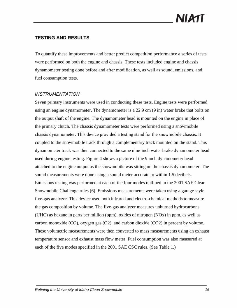
used during engine testing. Figure 4 shows a picture of the 9 inch dynamometer head
attached to the engine output as the snowmobile was sitting on the chassis dynamometer. The
sound measurements were done using a sound meter accurate to within 1.5 decibels.
Emissions testing was performed at each of the four modes outlined in the 2001 SAE Clean
Snowmobile Challenge rules [6]. Emissions measurements were taken using a garage-style
five-gas analyzer. This device used both infrared and electro-chemical methods to measure
the gas composition by volume. The five-gas analyzer measures unburned hydrocarbons
(UHC) as hexane in parts per million (ppm), oxides of nitrogen (NOx) in ppm, as well as
carbon monoxide (CO), oxygen gas (O2), and carbon dioxide (CO2) in percent by volume.
These volumetric measurements were then converted to mass measurements using an exhaust
temperature sensor and exhaust mass flow meter. Fuel consumption was also measured at
each of the five modes specified in the 2001 SAE CSC rules. (See Table 1.)
Refining the University of Idaho Clean Snowmobile 16
Figure 4 Dynamometer mounted to engine
EMISSIONS AND FUEL CONSUMPTION
Emissions and fuel consumption were measured at four specific operating points prior to any
modifications to the 2001 design. The operating points take the form of a percent of the
maximum vehicle or engine speed and a percent of the maximum vehicle or engine torque.
The 2001 SAE CSC scoring was based on measurements at these points. When measuring
engine-based parameters the torque used is the torque at the engine output and the speed is
the engine speed in RPM. When measuring chassis-based parameters the torque is the torque
produced at the track, and the speed is the track speed in miles per hour. The formulation of
each of these specific points is covered in detail in a paper by the Southwest Research
Institute [7]. This paper references five specific modes. However, during the 2001
competition measurements at mode 4 were not taken. Since our intention was to compare our
data to those taken at the 2001 CSC competition, mode 4 data were not taken in the following
tests. Table 1 shows the percentage of maximum engine torque and speed that corresponds to
each operating mode. Included in the table are the specific speed and torque values used
while testing the University of Idaho snowmobile.
Refining the University of Idaho Clean Snowmobile 17
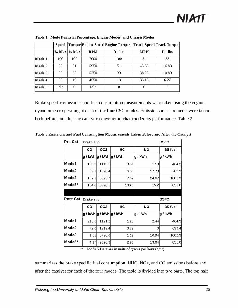
Table 1. Mode Points in Percentage, Engine Modes, and Chassis Modes
Speed Torque Engine Speed Engine Torque Track Speed Track Torque
% Max % Max RPM ft - lbs MPH ft - lbs
Mode 1 100 100 7000 100 51 33
Mode 2 85 51 5950 51 43.35 16.83
Mode 3 75 33 5250 33 38.25 10.89
Mode 4 65 19 4550 19 33.15 6.27
Mode 5 Idle 0 Idle 0 0 0
Brake specific emissions and fuel consumption measurements were taken using the engine
dynamometer operating at each of the four CSC modes. Emissions measurements were taken
both before and after the catalytic converter to characterize its performance. Table 2
Table 2 Emissions and Fuel Consumption Measurements Taken Before and After the Catalyst
Pre-Cat Brake spc BSFC
CO CO2 HC NO BS fuel
g / kWh g / kWh g / kWh g / kWh g / kWh
Mode1 193.3 1113.5 3.51 17.3 464.3
Mode2 99.1 1828.4 6.56 17.78 702.9
Mode3 107.1 3225.7 7.62 24.67 1001.3
Mode5* 134.8 8928.1 106.6 15.2 851.6
Post-Cat Brake spc BSFC
CO CO2 HC NO BS fuel
g / kWh g / kWh g / kWh g / kWh g / kWh
Mode1 216.6 1121.2 1.25 2.44 464.3
Mode2 72.8 1919.4 0.79 0 699.4
Mode3 1.61 3790.6 1.19 10.94 1002.3
Mode5* 4.17 9026.3 2.95 13.64 851.6
* Mode 5 Data are in units of grams per hour (g/hr)
summarizes the brake specific fuel consumption, UHC, NOx, and CO emissions before and
after the catalyst for each of the four modes. The table is divided into two parts. The top half
Refining the University of Idaho Clean Snowmobile 18
of the table contains data taken before the catalytic converter, and the bottom half contains
data taken after the catalytic converter. Since the data are presented in a mass per kilowatt-
hour, or brake specific form, the fifth mode data are instead presented in units of grams per
hour because there is little or no power being produced (although there are certainly
emissions produced at idle).
ENGINE AND CHASSIS
Preliminary engine, chassis, and sound tests were performed on the snowmobile prior to any
modifications. This provided a baseline to which the results of tests performed after all the
modifications could be compared. The baseline engine dynamometer test was performed to
develop lugging curves for engine torque and power. This was done by setting the engine
speed to values ranging from 7500 to 2000 RPM. At each engine speed, a load was applied to
the engine by the water brake. The magnitude of the load was just below the load required to
stall the engine at each RPM point. The torque at each point was then measured and plotted
on a graph with torque on the ordinate and engine RPM on the abscissa. This torque curve
illustrated the maximum torque produce by the engine and at which engine speed this torque
was produced.
The baseline chassis dynamometer testing was performed similarly, except that the
snowmobile track speed was varied between 96 and 32 kph (60 and 20 mph). The track
torque and power were then plotted on the ordinate with track speed along the abscissa to
form chassis torque and power curves. This provided a characterization of the track speed at
which the snowmobile produced the most torque and power.
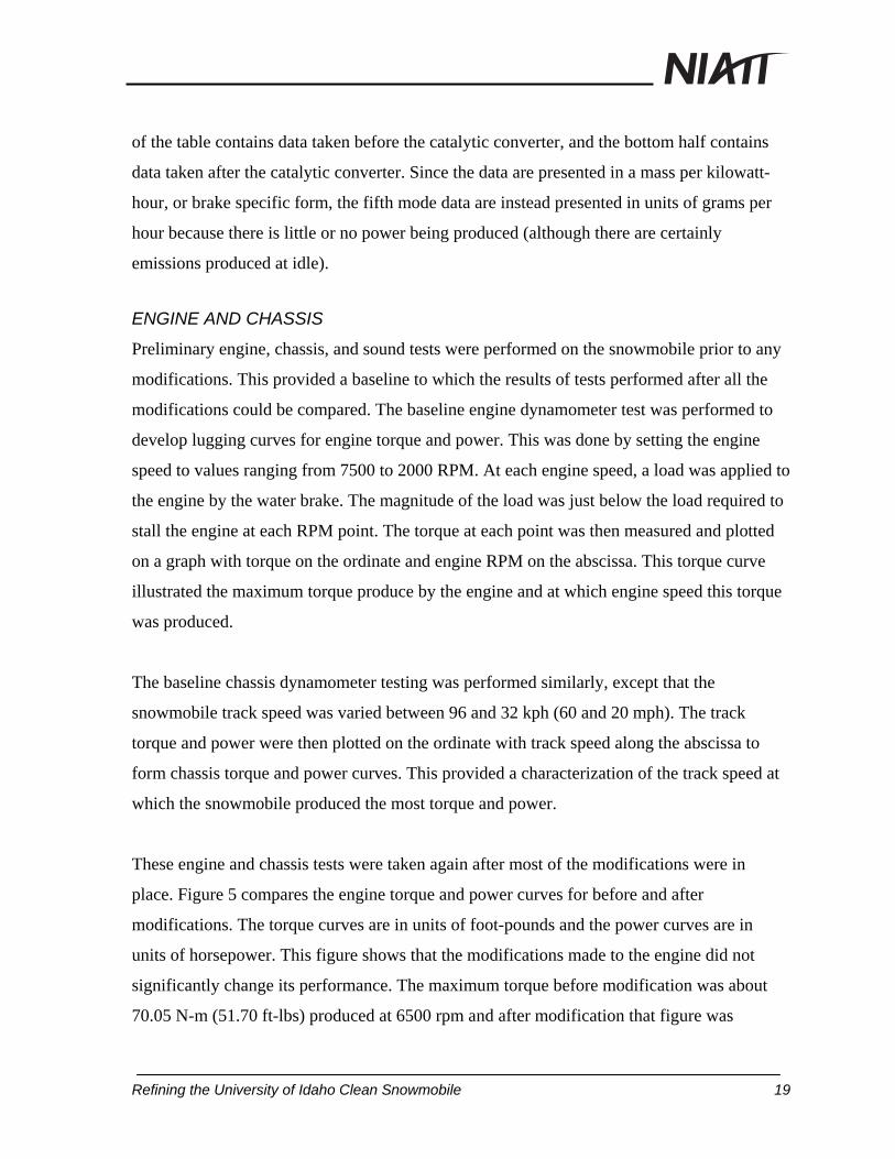
These engine and chassis tests were taken again after most of the modifications were in
place. Figure 5 compares the engine torque and power curves for before and after
modifications. The torque curves are in units of foot-pounds and the power curves are in
units of horsepower. This figure shows that the modifications made to the engine did not
significantly change its performance. The maximum torque before modification was about
70.05 N-m (51.70 ft-lbs) produced at 6500 rpm and after modification that figure was
Refining the University of Idaho Clean Snowmobile 19
reduced to 68.56 N-m (50.6 ft-lbs) produced at 6000 rpm. This represents a reduction of
about two percent. Based on the estimated error during testing, the change measured was not
significant. Figure 5 Engine torque and power Curves, before and after modification.
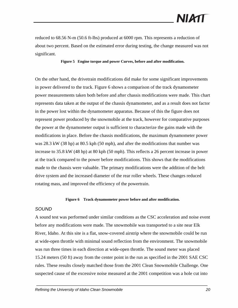
On the other hand, the drivetrain modifications did make for some significant improvements
in power delivered to the track. Figure 6 shows a comparison of the track dynamometer
power measurements taken both before and after chassis modifications were made. This chart
represents data taken at the output of the chassis dynamometer, and as a result does not factor
in the power lost within the dynamometer apparatus. Because of this the figure does not
represent power produced by the snowmobile at the track, however for comparative purposes
the power at the dynamometer output is sufficient to characterize the gains made with the
modifications in place. Before the chassis modifications, the maximum dynamometer power
was 28.3 kW (38 hp) at 80.5 kph (50 mph), and after the modifications that number was
increase to 35.8 kW (48 hp) at 80 kph (50 mph). This reflects a 26 percent increase in power
at the track compared to the power before modifications. This shows that the modifications
made to the chassis were valuable. The primary modifications were the addition of the belt
drive system and the increased diameter of the rear roller wheels. These changes reduced
rotating mass, and improved the efficiency of the powertrain.
Figure 6 Track dynamometer power before and after modification.
SOUND
A sound test was performed under similar conditions as the CSC acceleration and noise event
before any modifications were made. The snowmobile was transported to a site near Elk
River, Idaho. At this site is a flat, snow-covered airstrip where the snowmobile could be run
at wide-open throttle with minimal sound reflection from the environment. The snowmobile
was run three times in each direction at wide-open throttle. The sound meter was placed
15.24 meters (50 ft) away from the center point in the run as specified in the 2001 SAE CSC
rules. These results closely matched those from the 2001 Clean Snowmobile Challenge. One
suspected cause of the excessive noise measured at the 2001 competition was a hole cut into
Refining the University of Idaho Clean Snowmobile 20
left side body panel to help cool the clutches. It was hypothesized that the presence of this
hole allowed clutch noise to escape. During the testing done at Elk River, measurements
were taken before any modifications with the cooling hole first open, and then covered.
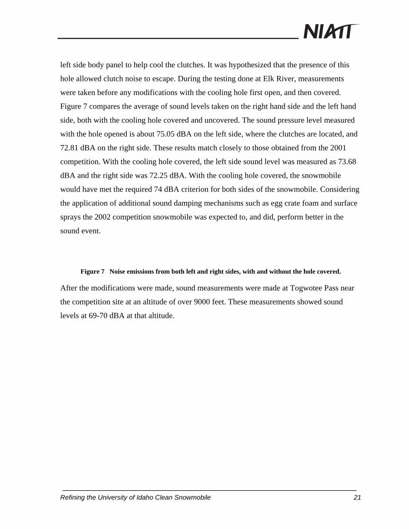
Figure 7 compares the average of sound levels taken on the right hand side and the left hand
side, both with the cooling hole covered and uncovered. The sound pressure level measured
with the hole opened is about 75.05 dBA on the left side, where the clutches are located, and
72.81 dBA on the right side. These results match closely to those obtained from the 2001
competition. With the cooling hole covered, the left side sound level was measured as 73.68
dBA and the right side was 72.25 dBA. With the cooling hole covered, the snowmobile
would have met the required 74 dBA criterion for both sides of the snowmobile. Considering
the application of additional sound damping mechanisms such as egg crate foam and surface
sprays the 2002 competition snowmobile was expected to, and did, perform better in the
sound event.
Figure 7 Noise emissions from both left and right sides, with and without the hole covered.
After the modifications were made, sound measurements were made at Togwotee Pass near
the competition site at an altitude of over 9000 feet. These measurements showed sound
levels at 69-70 dBA at that altitude.
Refining the University of Idaho Clean Snowmobile 21

FINDINGS; CONCLUSIONS; RECOMMENDATIONS
Competition Results and Conclusions
Based on our results during the competition, it is evident that the modifications made to the
snowmobile were well worthwhile. The modifications made to the engine did not directly
improve the snowmobile performance, but most certainly extended the life of the engine and
the results of the engine tests showed that the engine was operating properly during the 2001
competition. The tests also revealed that without extensive alteration the performance of the
BMW K75RT engine cannot easily be improved. The results of the chassis tests showed that
significantly increasing chassis efficiency is possible with only a small amount of work. The
power at the track was increased by 26 percent with no change in engine power. Since engine
performance was unaltered, it was expected that the emissions and fuel consumption of the
snowmobile would be maintained at an acceptable level. The 2001 snowmobile achieved a
59 percent reduction in CO, an 84.1 percent reduction in UHC, and a 39.7 percent reduction
in NOx. The reduction in the combined UHC and NOx was 83.5 percent. Figure 8 shows the
results for the University of Idaho Snowmobile in the 2002 competition. The 2002 UI
snowmobile achieved an 82 percent reduction in CO and over a 99.5 percent reduction in
UHC when compared to the control snowmobile, second best in the competition, and one of
only six snowmobiles to meet the emissions requirements.
Figure 8 Emissions results in the 2002 CSC competition
The sound emissions were reduced by the addition of a larger muffler and better hood
sealing. These were sufficient to reduce the sound levels below the 74 dBA at required by the
competition. The University of Idaho was one of only three schools whose snowmobiles met
this stringent requirement. In comparison, the standard stock snowmobile used as a control
was measured at 80 dBA. Figure 9 shows the sound emissions results for the University of
Idaho in both 2001 and 2002.
Figure 9 Sound results in the 2001 and 2002 CSC competitions
Refining the University of Idaho Clean Snowmobile 22

The University of Idaho 2002 CSC competition snowmobile was one of only four
snowmobiles to complete the 100 mile endurance run. It did so with a fuel economy of over
18 miles per gallon, best in the competition, and an improvement of 56 percent over the
control snowmobile.
The University of Idaho 2002 snowmobile also won the World Championship Hill Climb in
Jackson Hole, and was named "King of the Hill" for the SAE CSC Division for 2002 (taking
home both the belt buckle and bragging rights). In combination with the performance in the
events of handling and acceleration, the Hill Climb victory also assured the University of
Idaho the Award for Best Performance.
The University of Idaho also scored third in the Design Paper, second in the Static Display,
and fifth in the Oral Presentation, and was awarded the "Best Design" trophy.
Overall, the Idaho team was awarded First Place in the 2002 CSC competition, with a total of
1171 points. We achieved the Best Fuel Economy, Best Design, Best Performance, and King
of the Hill awards. The modifications made to the 2001 competition snowmobile certainly
were worthwhile.
post-competition emissions testing
Based on performance during the competition, the top five finishers in the emissions portion
of the competition were invited to bring their snowmobiles to the Southwest Research
Institute (SwRI) for more detailed emissions testing. The University of Idaho was one of two
student teams who attended. Detailed emissions testing of the type done at the 2001 CSC [7]
were performed on the student-built sleds, and also on two commercially available four-
stroke snowmobiles. The University of Idaho 2002 competition snowmobile was the cleanest
one tested. Figures 10 and 11 show the results of the testing for carbon monoxide (CO) and
unburned hydrocarbons (UHC). The emissions results are also shown for a typical two-stroke
touring snowmobile.
Details of the testing methods and results are given in reference [8].
Refining the University of Idaho Clean Snowmobile 23

Figure 10 Emissions results for carbon monoxide at SwRI
Figure 11 Emissions results for unburned hydrocarbons at SwRI
Refining the University of Idaho Clean Snowmobile 24
REFERENCES 1. American Council of Snowmobile Associations, East Lansing, Michigan,
www.snowmobileacsa.org/page.cfm/16/
2. Fussell, L., Paddleford, B., “The SAE Clean Snowmobile Challenge 2002 Rules,”
Jackson, WY, 2002.
3. Auth, P., Millhorn, S., Beeler, Z., and Den Braven, K., “Making the Connection: the
University of Idaho Clean Snowmobile,” SAE 2001-01-3657, Sept. 2001.
4. “Gasoline Fuel Injection System L-Jetronic,” Robert Bosch GmbH, Germany, 1999.
5. “Repair Manual K-Models,” BMW Motorrad GmbH + Co., Munich, Germany, 1991.
6. Fussell, L., Paddleford, B., “The SAE Clean Snowmobile Challenge 2001 Rules,”
Jackson, WY, 2001.
7. Wright, C., White, J., ”Development and Validation of a Snowmobile Engine
Emission Test Procedure,” SAE 982017, Warrendale, PA, 1998.
8. Lela, C., White, J., “Laboratory Testing of Snowmobile Emissions”, Southwest
Research Institute Final Report 08.05486, July 2002.
ACKNOWLEDGEMENTS The University of Idaho Clean Snowmobile team would like to give special
acknowledgement to the National Institute for Advanced Transportation Technology
(NIATT) in the College of Engineering at the University of Idaho for their generous support
throughout this project. The team would also like to thank Eric Clarke for his patience and
assistance during the testing phase of this project.
Refining the University of Idaho Clean Snowmobile 25