Reference system for wire EDM machining. The standard range. · traditionally use wire EDM products...
84
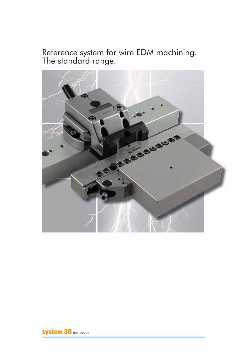
Reference system for wire EDM machining. The standard range.
Transcript of Reference system for wire EDM machining. The standard range. · traditionally use wire EDM products...
Reference system for wire EDM machining.The standard range.

3
A CHANGINGWORLD
Our world is constantly changing and so is the manufacturing industry. The catalogue you are holding is one result of the merger of System 3R and Mecatool.
Today the entire joint product range is being developed, made and marketed under the System 3R brand. But there’s no need to worry about your existing equipment, since System 3R will make sure that it can be integrated into the new product range.
The catalogue has two main sections – an orange section for customers who traditionally use wire EDM products from System 3R, and a blue section which is mainly for users of wire EDM accessories which used to be made by Mecatool. In both sections you will find adapter elements that give you free access to the entire product range, regardless of which system you used before.
A green tick in the product boxes indicates that the product will normally be shipped within two weeks, provided that it is in stock when the order is placed.
Dimensions and weights stated in the product boxes are not normative unless this is expressly stated.

44
STEP 3 – AUTOMATIONWith a reference system and a pneumatic chuck on the machine table, you have laid a firm foundation for the crucial step towards maximised machine utilisation – automation.
Add a pallet changer to your machine and you have created an automated production cell. A cell that can generate revenue 24 hours a day, weekdays and weekends, all year round!
THREE STEPS TO SUCCESSThe route to rational production in wire EDM machines can be summarised in three steps – mounting, reference system and automation.
STEP 1 – MOUNTINGFirst of all, the workpiece needs to be positioned and secured in the working area of the machine, preferably on the zero line, and with the risk of collision with the machine’s wire guides reduced to a minimum. And so firmly that it can handle the high flushing pressures of modern machines.
STEP 2 – REFERENCE SYSTEMOnce the problem of effective mounting of the workpiece in the machine has been solved, the next step is to minimise downtimes when retooling the machine.
Technical developments of the machines in recent years have resulted in significantly higher material removal rates. But you won’t benefit from this potential if the machine is idle for lengthy, troublesome retooling. So the aim must be to minimise retooling times with the machine idle.
With a reference system you can prepare and preset the workpiece away from the machine, then lift it in and secure it in the machine – quickly and precisely – with minimised downtime and consequent better utilisation of machine capacity.

5
CONTENTS
Basic equipment, WEDM ............................................................................................ page 6Basic equipment, Macro............................................................................................. page 8Mounting heads ........................................................................................................ page 13Holders and vices for mounting in mounting heads...................................................... page 18Chuck adapters ......................................................................................................... page 24Holders for mounting in chuck adapters...................................................................... page 28Adapter elements....................................................................................................... page 313Ruler ruler system..................................................................................................... page 333P three-point mounting............................................................................................. page 37Presetting and inspection............................................................................................ page 38Rotating spindles and accessories ............................................................................... page 41Basic equipment, ICS ICS ................................................................................................. page 42ICS Zeroline .............................................................................................................. page 43ICS guide elements ................................................................................................... page 48ICS vertical-guide elements & adaptations................................................................... page 52Unimatic ................................................................................................................... page 53Unimatic pallets......................................................................................................... page 56Unimatic twin pallet & frame ...................................................................................... page 57Unimatic accessories.................................................................................................. page 58ICS clamping elements............................................................................................... page 59ICS clamping elements A............................................................................................ page 60ICS clamping elements B............................................................................................ page 62ICS clamping elements C ........................................................................................... page 65Unimatic clamping elements ...................................................................................... page 66Electrode clamping systems Unimatic / ICS ................................................................. page 69System adapters......................................................................................................... page 70Unimatic presetting stations........................................................................................ page 71Specific solutions........................................................................................................ page 72Frame systems ........................................................................................................... page 73Accessories................................................................................................................ page 74Automation ............................................................................................................... page 75Index......................................................................................................................... page 78
6
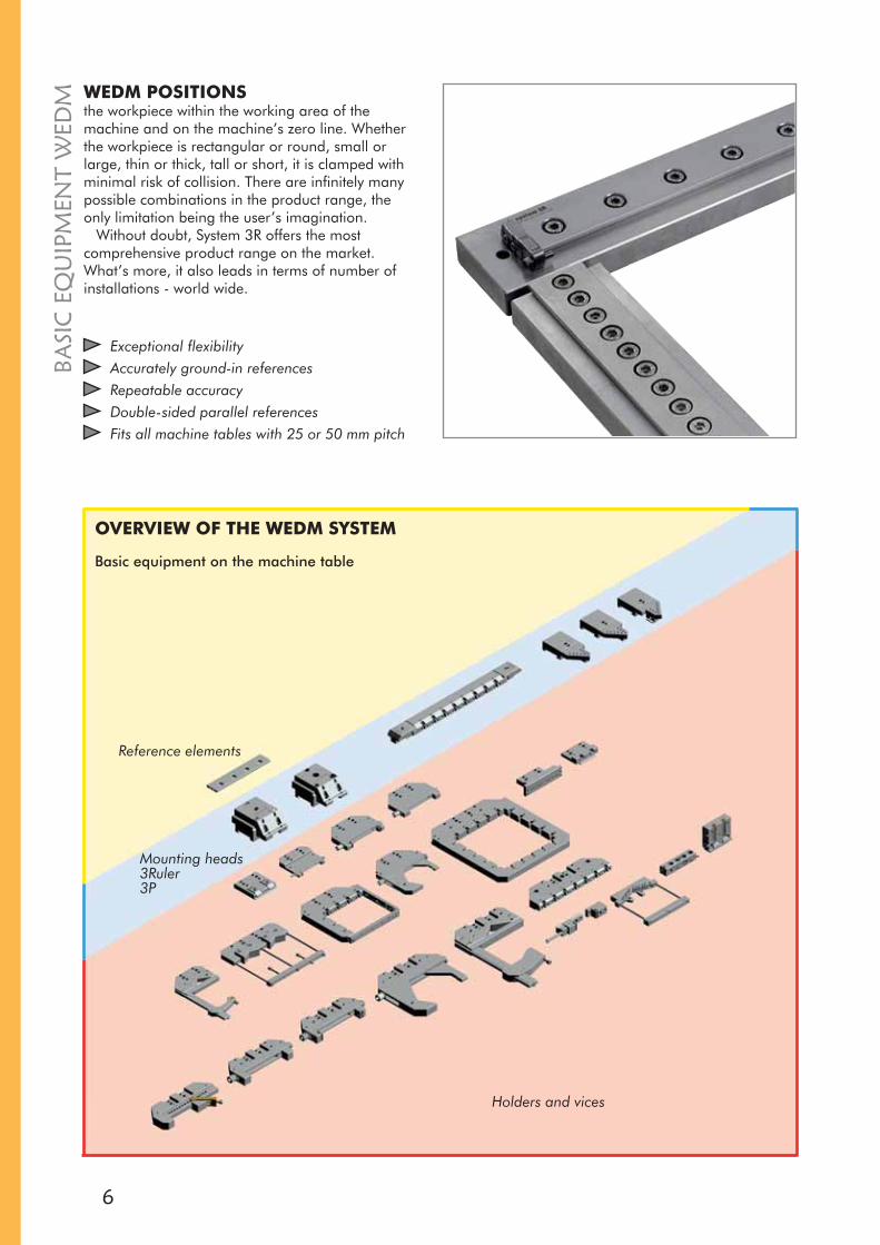
WEDM POSITIONSthe workpiece within the working area of the machine and on the machine’s zero line. Whether the workpiece is rectangular or round, small or large, thin or thick, tall or short, it is clamped with minimal risk of collision. There are infinitely many possible combinations in the product range, the only limitation being the user’s imagination.
Without doubt, System 3R offers the most comprehensive product range on the market. What’s more, it also leads in terms of number of installations - world wide.
Exceptional flexibilityAccurately ground-in referencesRepeatable accuracyDouble-sided parallel referencesFits all machine tables with 25 or 50 mm pitch
OVERVIEW OF THE WEDM SYSTEM
Basic equipment on the machine table
Reference elements
Mounting heads 3Ruler3P
Holders and vices
BASI
C E
QU
IPM
ENT
WED
M

7
BASIC
EQU
IPMEN
T WED
MReference element WEDM3R-200.XJ-XReference elements for machines with zero-line table. Thelength (L), hole spacing (C) and hole edge spacing (B) of the hardened reference elements are matched to the machine inquestion.
Note: When ordering, state machine make and type.• Supplied with end stops
Reference element WEDM 3R-200.1J-UUniversal 150 mm reference element, with oval holes,for all machines that have M8 holes in the machine table, 30 to 40 mm from the edge of the table.• Weight 0.4 kg
Reference stop3R-225Can be moved infinitely along the entire reference element.• Hardened• Weight 0.4 kg
Reference stop3R-225.1Mounts in any of the mounting holes in the reference element.• Weight 0.15 kg

8
X
kg
kg
X
BASI
C E
QU
IPM
ENT
– M
AC
RO WITH A MACROCHUCK
as basic equipment on the machine table, you caninterconnect all your machines to create a singlesystem. Move the workpiece from the wire EDM machine to the grinding machine or the die-sinking machine without subsequent alignment – quickly and precisely.
If you choose a pneumatic Macro chuck, you can operate round-the-clock production if you wish.
Allows fully automated productionLinks all your machines togetherZ-references with automatic air-blast cleaningX and Y references of cemented carbideRepetition accuracy 0.002 mmTurbo locking – enhanced clamping force
RECOMMENDATIONAA S FOR LOADING IN MACRO CHUCKS
Article number Max torque CapacityX=100 mm
3R-602.4.1 8 Nm 7-8 kg3R-602.27-1 8 Nm 7-8 kg3R-600.24-4RS 8 Nm 7-8 kg3R-60.360-X 8 Nm 7-8 kg
Article number Max torque CapacityX=150 mm
3R-602.27-1 18 Nm 12 kg3R-602.10 22,5 Nm 15 kg3R-602.10HP 30 Nm 20 kg3R-602.27 30 Nm 20 kg3R-602.26 30 Nm 20 kg3R-602.12HP 45 Nm 30 kg
Note: The pneumatic chucks require an airpressure of 6±1 bar.
Table chucks with vertical mounting of the workpiece.TT
Table chucks with horizontal mounting of the workpieceTT
9
BASIC
EQU
IPMEN
T – MA
CR
O
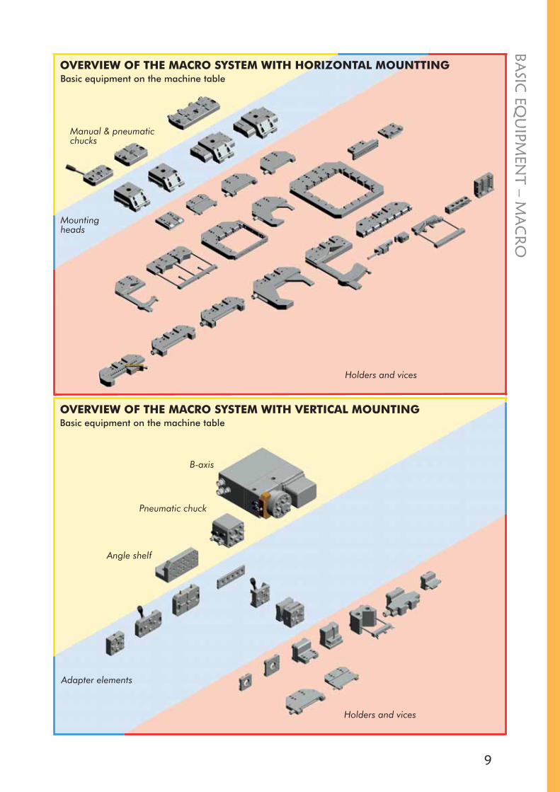
Holders and vices
Mountingheads
Adapter elements
Holders and vices
OVERVIEW OF THE MACRO SYSTEM WITH VERTICAL MOUNTING
OVERVIEW OF THE MACRO SYSTEM WITH HORIZONTAL MOUNTTINGBasic equipment on the machine table
Basic equipment on the machine table
Manual & pneumatic chucks
Angle shelf
Pneumatic chuck
B-axis
10
BASI
C E
QU
IPM
ENT
– M
AC
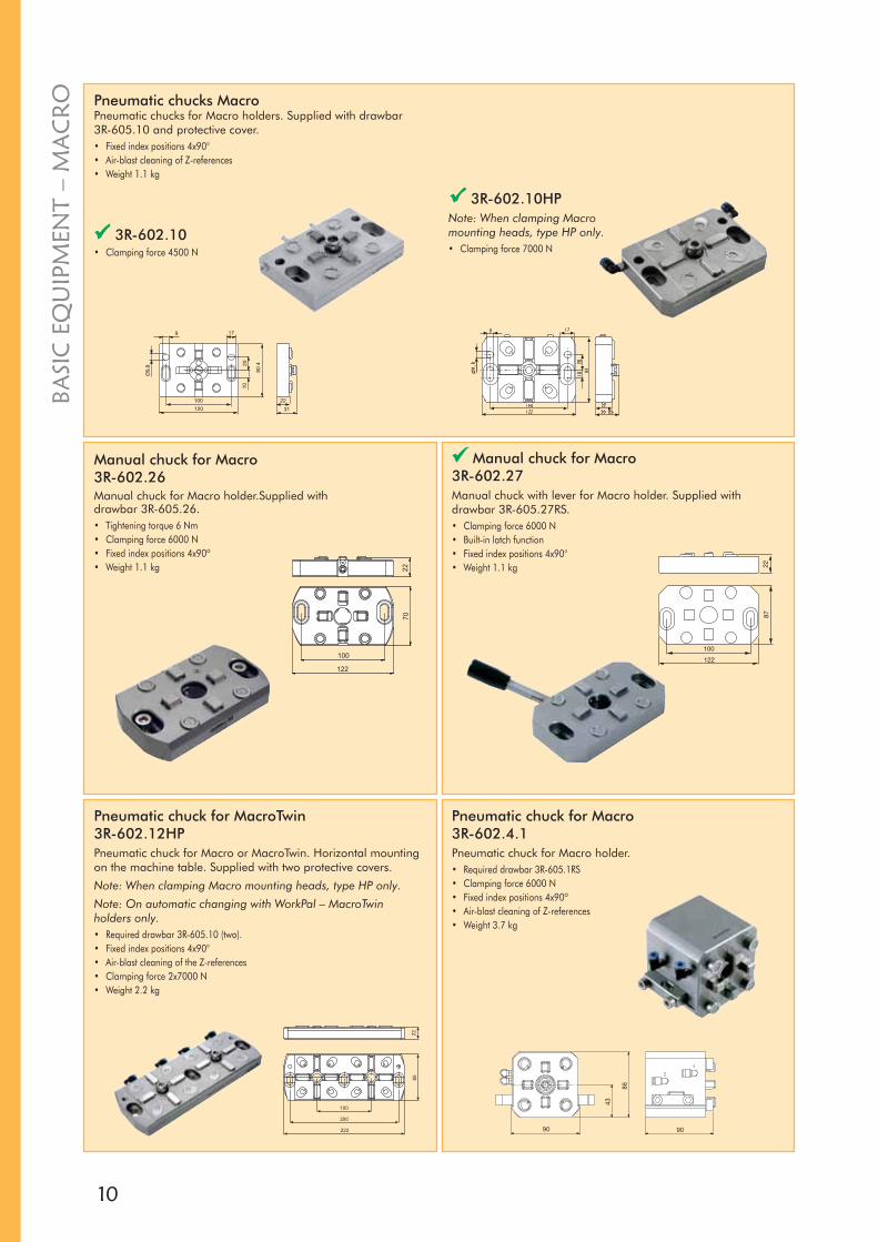
RO Pneumatic chucks Macro
Pneumatic chucks for Macro holders. Supplied with drawbar 3R-605.10 and protective cover.• Fixed index positions 4x90°• Air-blast cleaning of Z-references• Weight 1.1 kg
3R-602.10• Clamping force 4500 N
3R-602.10HPNote: When clamping Macro mounting heads, type HP only.• Clamping force 7000 N
Pneumatic chuck for Macro 3R-602.4.1Pneumatic chuck for Macro holder.• Required drawbar 3R-605.1RS• Clamping force 6000 N• Fixed index positions 4x90º• Air-blast cleaning of Z-references• Weight 3.7 kg
Pneumatic chuck for MacroTwin3R-602.12HPPneumatic chuck for Macro or MacroTwin. Horizontal mounting on the machine table. Supplied with two protective covers.
Note: When clamping Macro mounting heads, type HP only.
Note: On automatic changing with WorkPal – MacroTwin holders only.• Required drawbar 3R-605.10 (two).• Fixed index positions 4x90°• Air-blast cleaning of the Z-references• Clamping force 2x7000 N• Weight 2.2 kg
Manual chuck for Macro3R-602.26Manual chuck for Macro holder.Supplied with drawbar 3R-605.26.• Tightening torque 6 Nm• Clamping force 6000 N• Fixed index positions 4x90º• Weight 1.1 kg
Manual chuck for Macro3R-602.27Manual chuck with lever for Macro holder. Supplied with drawbar 3R-605.27RS.• Clamping force 6000 N• Built-in latch function• Fixed index positions 4x90°• Weight 1.1 kg
11
BASIC
EQU
IPMEN
T – MA
CR
O
Angle shelf3R-201.5Mounts directly on the machine table. For vertical mounting of a Macro chuck or short reference element in the machine. Supplied with M8 screw and washer (x3).• Weight 4.2 kg
3R-605.1RS• Drawbar Ø20x57.1 mm with
flushing hole Ø7 mm• Rust-resistant• Supplied singly
Drawbars
3R-605.26• Drawbar Ø20x32 mm• Rust-resistant• Supplied singly
3R-605.10• Drawbar Ø20x13 mm• Rust-resistant• Supplied singly
3R-605.27RS• Drawbar Ø20x27 mm• Rust-resistant• Supplied singly
Locking ring key3R-605-GETo lift the drawbar locking ring.• Supplied in sets of two
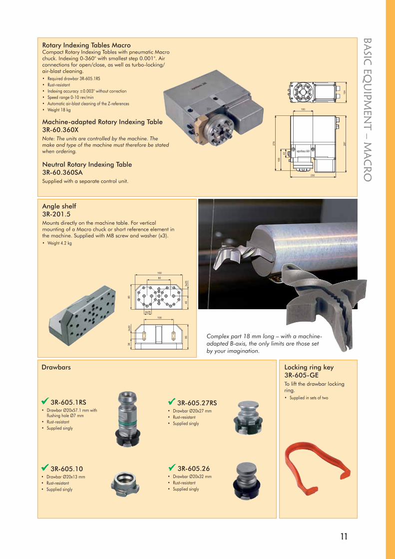
Rotary Indexing Tables MacroCompact Rotary Indexing Tables with pneumatic Macro chuck. Indexing 0-360° with smallest step 0.001°. Air connections for open/close, as well as turbo-locking/air-blast cleaning.• Required drawbar 3R-605.1RS• Rust-resistant• Indexing accuracy ±0.003° without correction• Speed range 0-10 rev/min• Automatic air-blast cleaning of the Z-references• Weight 18 kg
Machine-adapted Rotary Indexing Table3R-60.360XNote: The units are controlled by the machine. The make and type of the machine must therefore be stated when ordering.
Neutral Rotary Indexing Table3R-60.360SASupplied with a separate control unit.
Complex part 18 mm long – with a machine-adapted B-axis, the only limits are those set by your imagination.
12
BASI
C E
QU
IPM
ENT
– M
AC
RO
Insulating kitK-30266Insulating kit for 3R-602.10, 3R-602.10HP, 3R-602.26 and 3R-602.27.
Actuator3R-611.4Unit for operation of pneumatic chucks Two functions – open/closed.
Spare parts kit3R-SSP014Spare parts kit including instructions for 3R-602.10.
Spare parts kit3R-SSP044Spare parts kit including instructions for 3R-602.10HP.
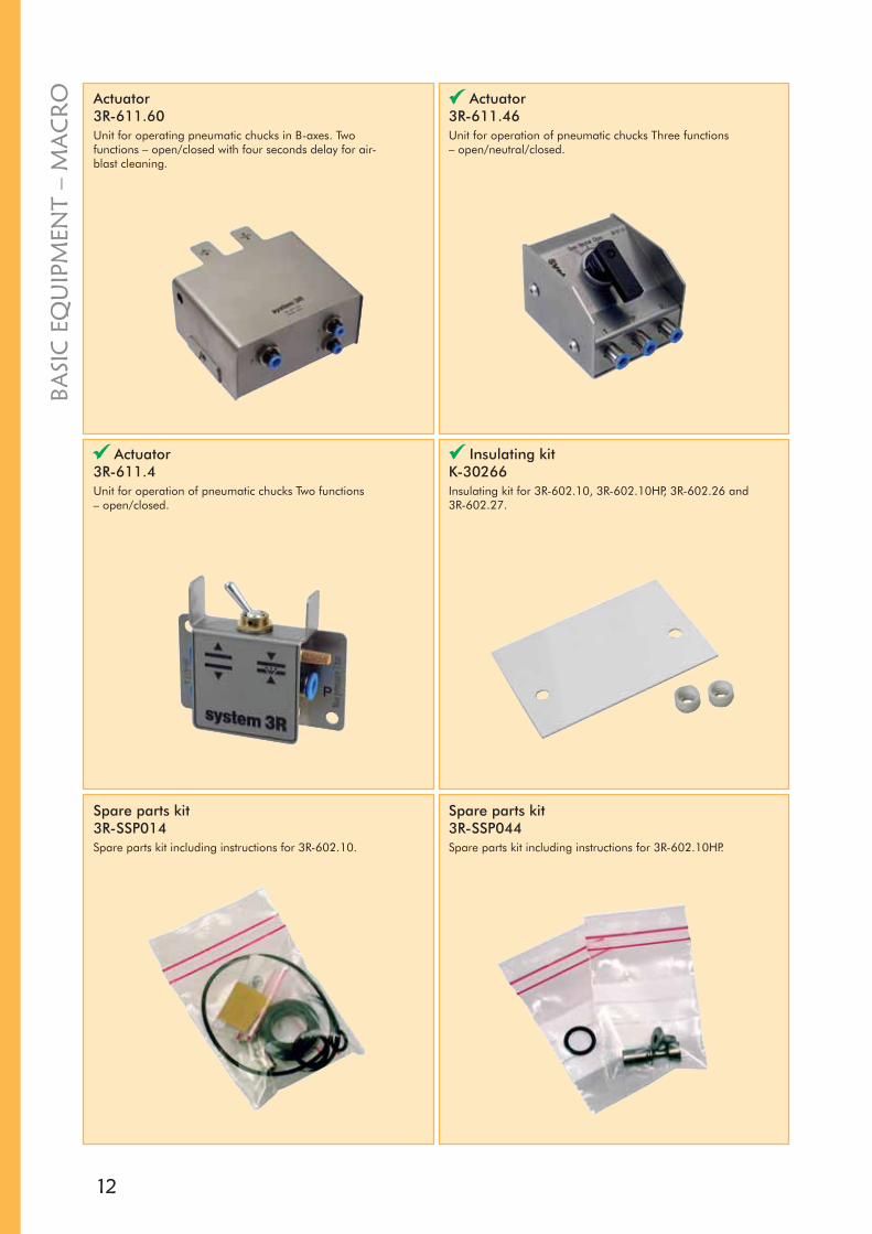
Actuator3R-611.60Unit for operating pneumatic chucks in B-axes. Two functions – open/closed with four seconds delay for air-blast cleaning.
Actuator3R-611.46 Unit for operation of pneumatic chucks Three functions – open/neutral/closed.

12 3
13
MO
UN
TING
HEA
DS
RAPID SETUPis essential if you want to benefit from the material removal capacity and the accuracy offered by modern machines. However, faster machines with increased flushing pressure cause resonance and vibration. So in order to fully utilise the capability of the machines it is necessary to have stable tools and workpiece mountings.
Setup done in secondsGives maximum workpiece precision Utilises the machine capacityMore stable than any other systemMinimal vibrationMinimises resonance
PRE-SET IN THREE AXESwith System 3Rs levelling adapter. This can be done with an accuracy of thousandths of a millimetre!
The simple, directly measurable references of the levelling adapter mean that presetting can be done on an ordinary surface plate, using one of System 3R’s presetting stones.
Preset away from the machine. Lift the preset “package” into place – levelling adapter, holder and workpiece – fix with a few simple manual operations and start the machine. Simple, quick and precise.
14
3R-266.4
3R-262HP
3R-266.12HP
3R-226.4
3R-272HP
3R-282.12HP
3R-232S
3R-267.2
C 950 470
3R-266.5
MO
UN
TIN
G H
EAD
S
MAC
HIN
E TA
BLE
REFE
REN
CE
ELEM
ENTS
CH
UC
KM
ACRO
TWIN
CH
UC
KM
ACRO
HO
LDER
AND
FIXT
URE
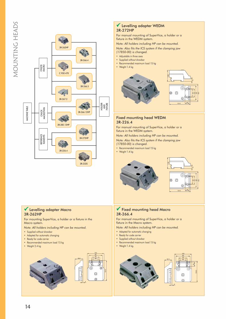
Fixed mounting head WEDM3R-226.4For manual mounting of SuperVice, a holder or a fixture in the WEDM system.
Note: All holders including HP can be mounted.
Note: Also fits the ICS system if the clamping jaw (17850-00) is changed.• Recommended maximum load 15 kg• Weight 1.4 kg
Levelling adapter Macro 3R-262HPFor mounting SuperVice, a holder or a fixture in the Macro system.
Note: All holders including HP can be mounted.• Supplied without drawbar• Adapted for automatic changing• Ready for code carrier• Recommended maximum load 15 kg• Weight 2.4 kg
Levelling adapter WEDM 3R-272HPFor manual mounting of SuperVice, a holder or a fixture in the WEDM system.
Note: All holders including HP can be mounted.
Note: Also fits the ICS system if the clamping jaw (17850-00) is changed.• Adjustable in three axes• Supplied without drawbar• Recommended maximum load 15 kg• Weight 1.4 kg
Fixed mounting head Macro3R-266.4For manual mounting of SuperVice, a holder or a fixture in the Macro system.
Note: All holders including HP can be mounted.• Adapted for automatic changing• Ready for code carrier• Supplied without drawbar• Recommended maximum load 15 kg• Weight 1.4 kg.

15
63,545115,5
4,4 8,3
25
8,2
97
64
45°
103
90
3720
,5
13,25
63,545115,5
4,4 8,3
25
8,245°
103
90
3720
,5
13,25
MO
UN
TING
HEA
DS
Fixed mounting head Magnum MacroTwin3R-266.12HPFor manual mounting of Magnum holders in the MacroTwin system.
Note: All holders including HP can be mounted.• Can be adapted to automatic changing with 3R-W12-S• Supplied with drawbar 3R-605.10 x2• Ready for code carrier• Recommended maximum load 15 kg• Weight 3.1 kg
Levelling adapter Magnum MacroTwin 3R-282.12HPFor mounting Magnum holders in the MacroTwin system.
Note: All holders including HP can be mounted.• Adjustable in three axes• Can be adapted to automatic changing with 3R-W12-S• Supplied with drawbar 3R-605.10 x2• Ready for code carrier• Recommended maximum load 15 kg• Weight 3.1 kg
Fixed mounting head, Macro3R-266.5For mounting SuperVice, a holder or a fixture in the Macro system.
Note: All holders including HP can be mounted.• Can be adapted to automatic changing with 3R-WP1• Ready for code carrier• Supplied without drawbar• Recommended maximum load 15 kg• Weight 2.4 kg
Unimacro Adjusting palletC 950 470For manual mounting of Unimatic holders and Unimatic clamping elements in the Macro system. Adjusting pallet with dovetail guide adaptation.• Adjustment range ±0.2 mm for all three axes• Functional height 59 mm, Unimatic pallet placed onto Macro chuck • Weight 2.7 kg
16
MO
UN
TIN
G H
EAD
S
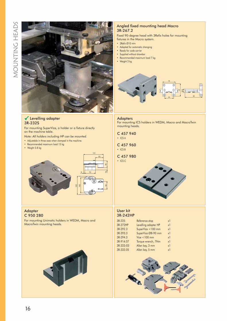
User kit3R-242HP3R-225 Reference stop x13R-272HP Levelling adapter HP x13R-292.3 SuperVice <100 mm x13R-293.3 SuperVice Ø8-90 mm x13R-294.3 Vice <100 mm x13R-914.07 Torque wrench, 7Nm x13R-333-03 Allen key, 3 mm x13R-333.05 Allen key, 5 mm x1
AdapterC 950 280For mounting Unimatic holders in WEDM, Macro and MacroTwin mounting heads.
AdaptersFor mounting ICS holders in WEDM, Macro and MacroTwin mounting heads.
C 457 940• ICS A
C 457 960• ICS B
C 457 980• ICS C
Angled fixed mounting head Macro3R-267.2Fixed 90-degree head with 3Refix holes for mounting fixtures in the Macro system.• 3Refix Ø10 mm• Adapted for automatic changing• Ready for code carrier• Supplied without drawbar• Recommended maximum load 7 kg• Weight 3 kg
Levelling adapter3R-232SFor mounting SuperVice, a holder or a fixture directly on the machine table.
Note: All holders including HP can be mounted.• Adjustable in three axes when clamped in the machine.• Recommended maximum load 15 kg• Weight 3.8 kg

17
MO
UN
TING
HEA
DS
User kit3R-242.82HP3R-239.1 Ruler vice x13R-272HP Levelling adapter HP x13R-292.66HP Magnum Holder HP x1
User kit3R-242S-13R-232S Levelling adapter x13R-292.3S Universal holder x13R-333.03 Allen key, 3 mm x13R-333.05 Allen key, 5 mm x1
User kit3R-242S-23R-232S Levelling adapter x13R-292.6S SuperVice Magnum x13R-333.03 Allen key, 3 mm x13R-333.05 Allen key, 5 mm x1
User kit3R-242S-33R-232 Levelling adapter x13R-293.33 Universal holder x13R-333.03 Allen key, 3 mm x13R-333.05 Allen key, 5 mm x1
User kit3R-242S-43R-602.2 Manual chuck x13R-262HP Levelling adapter Macro x13R-292.6S SuperVice Magnum x13R-605.26 Drawbar x13R-333.05 Allen key, 5 mm x145600-N03 Allen key, 3 mm x145600-N041 Allen key, 6 mm x1
18
X
Nm
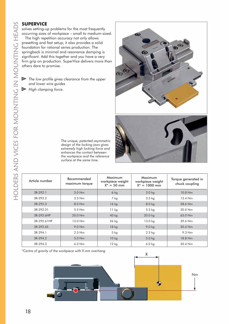
SUPERVICEsolves setting-up problems for the most frequently occurring sizes of workpiece – small to medium-sized.
The high repetition accuracy not only allows presetting and fast setup; it also provides a solid foundation for rational series production. The springback is minimal and resonance damping is significant. Add this together and you have a very firm grip on production. SuperVice delivers more than others dare to promise.
The low profile gives clearance from the upper and lower wire guidesHigh clamping force.
HO
LDER
S A
ND
VIC
ES F
OR
MO
UN
TIN
G IN
MO
UN
TIN
G H
EAD
S
3R-292.1 3.0 Nm 6 kg 3.0 kg 10.8 Nm
3R-292.2 3.5 Nm 7 kg 3.5 kg 12.4 Nm
3R-292.3 8.0 Nm 16 kg 8.0 kg 28.6 Nm
3R-292.31 5.5 Nm 11 kg 5.5 kg 20.0 Nm
3R-292.6HP 20.0 Nm 40 kg 20.0 kg 63.0 Nm
3R-292.61HP 13.0 Nm 26 kg 13.0 kg 39.6 Nm
3R-292.6S 9.0 Nm 18 kg 9.0 kg 30.4 Nm
3R-294.1 2.5 Nm 5 kg 2.5 kg 9.3 Nm
3R-294.2 5.0 Nm 10 kg 5.0 kg 18.8 Nm
3R-294.3 6.0 Nm 12 kg 6.0 kg 20.4 Nm
The unique, patented asymmetric design of the locking jaws gives extremely high locking force and enhances the contact between the workpiece and the reference surface at the same time.
*Centre of gravity of the workpiece with X mm overhang
Article number Torque generated in chuck coupling
Maximumworkpiece weightX* = 1000 mm
Maximumworkpiece weight
X* = 50 mm
Recommended maximum torque

19
3R-293.6HP
3R-292.31
3R-292.6S
3R-292.3
3R-292.6HP
3R-293.33
3R-292.3S
3R-293.3
3R-293.66HP
3R-237.1
3R-294.3
3R-237.2
3R-292.23
3R-294.2
3R-294.6
3R-292.61HP
3R-292.66HP
3R-294
3R-294.1
3R-292.1
3R-292.2
C 619 680
WO
RKPI
ECE
MO
UN
TIN
GH
EAD
S
HO
LDER
S AN
D V
ICES FO
R M
OU
NTIN
G IN
MO
UN
TING
HEA
DS

20
SuperVice3R-292.1For clamping rectangular workpieces up to 77 mm.• Tightening torque 4 Nm• Weight 0.6 kg
SuperVice3R-292.2For clamping rectangular workpieces up to 100 mm.• Tightening torque 3 Nm• Weight 0.9 kg
SuperVice3R-292.3For clamping rectangular workpieces up to 100 mm.• Tightening torque 7 Nm• Weight 1.1 kg
SuperVice3R-292.31Vice with solid jaws for clamping rectangular workpieces up to 100 mm.• Tightening torque 7 Nm• Weight 1.1 kg
SuperVice Magnum 3R-292.6HPVice for clamping rectangular workpieces up to 155 mm.
Note: Mounts on HP, Magnum or MacroTwin levelling adapter.• Tightening torque 15 Nm• Weight 2.8 kg
HO
LDER
S A
ND
VIC
ES F
OR
MO
UN
TIN
G IN
MO
UN
TIN
G H
EAD
S

21
SuperVice Magnum3R-292.6SVice for clamping rectangular workpieces up to 150 mm.
Note: Mounts on HP, Magnum or MacroTwin levelling adapter.• Tightening torque 10 Nm• Weight 2.7 kg
SuperVice Magnum3R-293.6HPVice for clamping round workpieces 15-155 mm.
Note: Mounts on HP, Magnum or MacroTwin levelling adapter.• Recommended maximum workpiece weight 12 kg• Tightening torque 15 Nm• Weight 4.5 kg
SuperVice3R-293.3Vice for clamping round workpieces 8-90 mm.• Recommended maximum workpiece weight 7 kg• Tightening torque 7 Nm• Weight 1.7 kg
SuperVice Magnum3R-292.61HPVice with solid jaws for clamping rectangular workpieces up to 150 mm.
Note: Mounts on HP, Magnum or MacroTwin levelling adapter.• Tightening torque 15 Nm• Weight 2.8 kg
Universal holder3R-293.33Holder for round workpieces 8-100 mm, or rectangular workpieces up to 100 mm.• Recommended maximum workpiece weight 7 kg.• Tightening torque 3 Nm• Weight 1.5 kg
HO
LDER
S AN
D V
ICES FO
R M
OU
NTIN
G IN
MO
UN
TING
HEA
DS
Universal holder Magnum3R-293.66HPFor round workpieces15-150 mm diameter, or rectangular workpieces up to 150 mm.
Note: Mounts on HP, Magnum or MacroTwin mounting head.• Recommended maximum workpiece weight 12 kg.• Tightening torque 4 Nm• Weight 4.2 kg.

22
176
116
82
82
5
5
4650
247
4
9
415
0
4x 8,5
88
81
145
3,90
13
70
9
Universal holder3R-292.3SHolder for round workpieces up to 90 mm, or rectangular workpieces 100x90 mm.• Recommended maximum workpiece weight 7 kg.• Tightening torque 4 Nm• Weight 2.3 kg.
Holder3R-237.1Stainless steel hardened “do-it-yourself” holder. With start hole for wire EDM of the required shape for clamping one or more workpieces.• Recommended maximum weight 7 kg• Weight 1.2 kg
Vice3R-294.3For clamping workpieces up to 100 mm.• Tightening torque 7 Nm• Weight 0.7 kg
Holder3R-237.2For fixture, workpiece or 3R-239.2, 3R-239.3, 3R-294.1, 3R-294.2, 3R-294.6 and 3R-402.1.• Weight 0.6 kg
HO
LDER
S A
ND
VIC
ES F
OR
MO
UN
TIN
G IN
MO
UN
TIN
G H
EAD
S
Clamping bar to clamping frameC 619 670Clamping bar to use with ICS clamping frame A C 619 680.• Dimensions 88 x 20 x 26 mm • Overall height 26 mm (incl. support lips and clamping lips) • Weight 0.25 kg
Clamping frameC 619 680Carrier for flat round or cubic workpieces up to 80x80 mm.
Note: Mounts on HP, Magnum or MacroTwin levelling adapter.• Functional height 13 mm • Clamping range round or cubic up to 80 mm /
maximum workpiece height 12 mm• Maximum workpiece weight 1.5 kg • Maximum workpiece dimensions Ø 80 mm or 80x80 mm• Weight 0.9 kg
23
HO
LDER
S AN
D V
ICES FO
R M
OU
NTIN
G IN
MO
UN
TING
HEA
DS
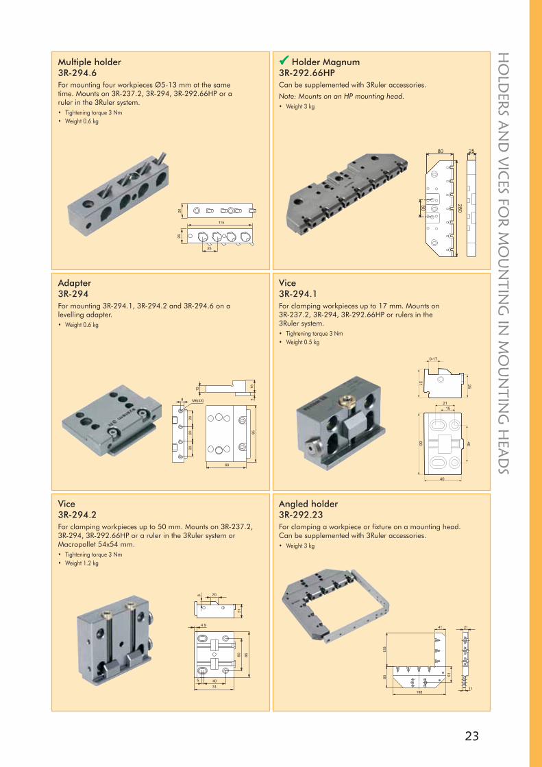
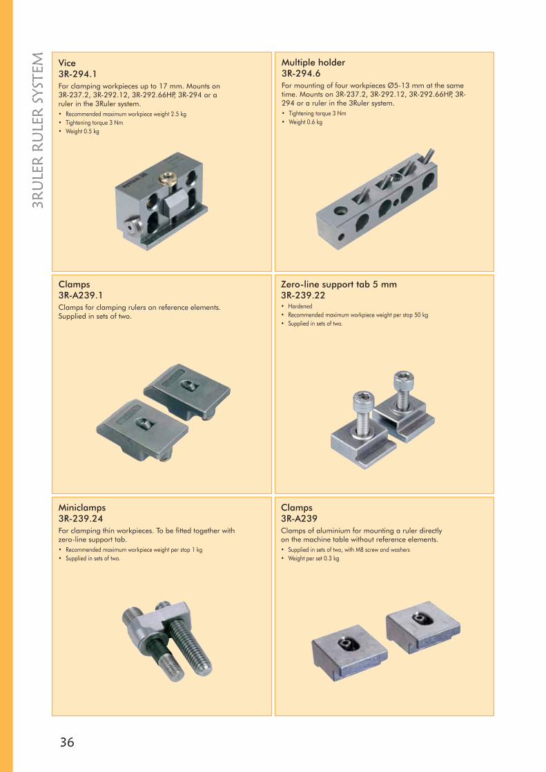
Multiple holder3R-294.6For mounting four workpieces Ø5-13 mm at the same time. Mounts on 3R-237.2, 3R-294, 3R-292.66HP or a ruler in the 3Ruler system.• Tightening torque 3 Nm• Weight 0.6 kg
Holder Magnum3R-292.66HPCan be supplemented with 3Ruler accessories.
Note: Mounts on an HP mounting head.• Weight 3 kg
Adapter3R-294For mounting 3R-294.1, 3R-294.2 and 3R-294.6 on a levelling adapter.• Weight 0.6 kg
Vice3R-294.1For clamping workpieces up to 17 mm. Mounts on 3R-237.2, 3R-294, 3R-292.66HP or rulers in the 3Ruler system.• Tightening torque 3 Nm• Weight 0.5 kg
Vice3R-294.2For clamping workpieces up to 50 mm. Mounts on 3R-237.2, 3R-294, 3R-292.66HP or a ruler in the 3Ruler system or Macropallet 54x54 mm.• Tightening torque 3 Nm• Weight 1.2 kg
Angled holder3R-292.23 For clamping a workpiece or fixture on a mounting head. Can be supplemented with 3Ruler accessories.• Weight 3 kg

24
3R-422.2
3R-402.1
3R-600.24-4RS
3R-602.27-1
3R-622.6
3R-466.40RS
3R-202
3R-252.1
3R-222.2
3R-605.5RS
3R-217-1
3R-405.21RS
3R-605.2RS
3R-406.9
3R-S
P643
5
3R-622.2
90825.02
3R-605.2RS90825.01
FIXT
URE
MAC
HIN
E TA
BLE
CH
UC
K M
ACRO
REFE
REN
CE
ELEM
ENTS
HO
LDER
MIN
I
CH
UC
K M
ACRO
REFE
REN
CE
ELEM
ENT
HO
LDER
MAC
ROJU
NIO
RH
OLD
ER M
ACRO
WO
RKPI
ECE
A WIDE RANGEof chuck adapters for clamping workpieces on pallets in the Macro, MacroJunior and Mini systems. An ever-growing field of application is the manufacture of precision parts for the medical industry; another is the manufacture of electrodes for die-sinking EDM.
The chuck adapters can interconnect all your machines to form a single system. All chuck adapters are hardened and rust-resistant.
CH
UC
K A
DA
PTER
S
25
CH
UC
K A
DA
PTERS
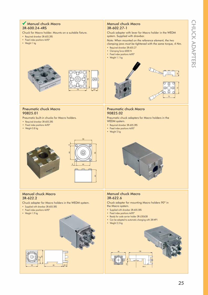
Manual chuck Macro3R-622.2Chuck adapter for Macro holders in the WEDM system. • Supplied with drawbar 3R-605.5RS• Fixed index positions 4x90º• Weight 1.9 kg
Manual chuck Macro 3R-622.6Chuck adapter for mounting Macro holders 90º in the Macro system.• Supplied with drawbar 3R-605.5RS• Fixed index positions 4x90º• Ready for code carrier holder 3R-U30638• Can be adapted to automatic changing with 3R-WP1• Weight 2.3 kg
Manual chuck Macro3R-600.24-4RSChuck for Macro holder. Mounts on a suitable fixture.• Required drawbar 3R-605.2RS• Fixed index positions 4x90º• Weight 1 kg
Manual chuck Macro3R-602.27-1Chuck adapter with lever for Macro holder in the WEDM system. Supplied with drawbar.
Note: When mounted on the reference element, the two clamping jaws must be tightened with the same torque, 4 Nm.• Required drawbar 3R-605.27• Clamping force 6000 N• Fixed index positions 4x90º• Weight 1.1 kg
Pneumatic chuck Macro90825.01Pneumatic built-in chucks for Macro holders. • Required drawbar 3R-605.2RS• Fixed index positions 4x90º• Weight 0.8 kg
Pneumatic chuck Macro90825.02Pneumatic chuck adapters for Macro holders in the WEDM system.• Required drawbar 3R-605.2RS• Fixed index positions 4x90º• Weight 2 kg

26
Manual chuck MacroJunior3R-422.2 Chuck adapter with axial locking screw for MacroJunior holders in the WEDM system.• Fixed index positions 3x120°• Weight 1.8 kg
Manual chuck MacroJunior3R-402.1Chuck for MacroJunior holder. Can be mounted on 3R-237.2, 3R-292.66HP, 3R-294, the 3Ruler system, or on Macro element 54x54.• Required drawbar 3R-405.21RS• Rust-resistant• Fixed index positions 3x120°• Weight 1.2 kg
Manual chuck adapter3R-406.9For horizontal mounting of MacroJunior holder in the Macro system. Screw locking.• Adapted for automatic changing• Rust-resistant• Fixed index positions 3x120°• Weight 1.2 kg
Manual chuck MacroJunior3R-466.40RSChuck adapter, stainless steel, for MacroJunior holders in the Macro system. Axial locking screw.• Fixed index positions 3x120° and 4x90º• Weight 0.4 kg
Adapter3R-SP6435Adapter element for mounting 3R-217-1 in the WEDM system.
3R-block Macro3R-217-1Manual block for Macro holder. Vertical or horizontal mounting on the machine table, or alternatively the WEDM system with the aid of 3R-SP6435.• Required drawbar 3R-605.2RS• Fixed index positions 24x15°• Vernier scale• Weight 5.4 kg
CH
UC
K A
DA
PTER
S
27
CH
UC
K A
DA
PTERS
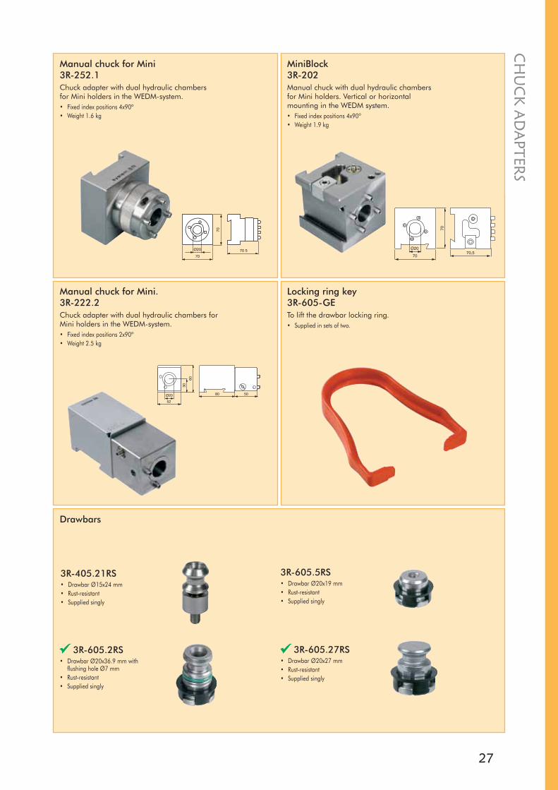
Locking ring key3R-605-GETo lift the drawbar locking ring.• Supplied in sets of two.
Drawbars
3R-405.21RS• Drawbar Ø15x24 mm• Rust-resistant• Supplied singly
Manual chuck for Mini3R-252.1Chuck adapter with dual hydraulic chambers for Mini holders in the WEDM-system.• Fixed index positions 4x90º• Weight 1.6 kg
MiniBlock3R-202 Manual chuck with dual hydraulic chambers for Mini holders. Vertical or horizontal mounting in the WEDM system.• Fixed index positions 4x90º• Weight 1.9 kg
3R-605.5RS• Drawbar Ø20x19 mm• Rust-resistant• Supplied singly
3R-605.2RS• Drawbar Ø20x36.9 mm with
flushing hole Ø7 mm• Rust-resistant• Supplied singly
Manual chuck for Mini.3R-222.2Chuck adapter with dual hydraulic chambers for Mini holders in the WEDM-system.• Fixed index positions 2x90º• Weight 2.5 kg
3R-605.27RS• Drawbar Ø20x27 mm• Rust-resistant• Supplied singly

28
X
THE HOLDERS HAVE BEEN ADAPTEDfor modern machines with high flushing pressure. These holders are mainly intended for clamping small to medium-sized workpieces on the zero line of the machine.
An example is the manufacture of electrodes for die-sinking EDM. The electrode is manufactured on its holder in the wire EDM machine. The electrode on its holder is then ready for immediate use in the die-sinking EDM machine, without intervening mounting operations and adjustments.
Pallet Macro 54x54 mm3R-651.7E-PHardened and precision-cast, with clearance holes for four fixing screws.
Note: Must be mounted on the workpiece/fixture before it is locked in a chuck. • Adapted for automatic changing• Parallel-ground top and bottom faces• Fixed index positions 4x90º• Rust-resistant• Supplied in sets of eight• Weight per set 1.2 kg
Pallet Macro 70x70 mm3R-601.7E-PHardened and precision-cast, with clearance holes for eight fixing screws.
Note: Must be mounted on the workpiece/fixture before it is locked in a chuck. • Adapted for automatic changing• Parallel-ground top and bottom faces• Fixed index positions 4x90º• Rust-resistant• Supplied in sets of five• Weight per set 3 kg
HO
LDER
S FO
R M
OU
NTI
NG
IN C
HU
CK
AD
APT
ERS
3R-613.4 3.0 Nm 6 kg 3.0 kg
3R-232.8 12.5 Nm 25 kg 12.5 kg
3R-613.6 12.5 Nm 25 kg 12.5 kg
3R-213.4 3.0 Nm 6 kg 3.0 kg
Article numberMaximum
workpiece weightX* = 1000 mm
Maximumworkpiece weight
X* = 50 mm
Recommended maximum torque
*Centre of gravity of the workpiece with X mm overhang

29
HO
LDER
S FOR
MO
UN
TING
IN C
HU
CK
AD
APTER
S
Macro V-holder3R-207.6For clamping round workpieces 8-70 mm, or rectangular workpieces 10-52 mm in the Macro system.• Hardened• Rust-resistant• Recommended maximum workpiece weight 8 kg• Weight 2 kg
SuperVice Macro3R-613.4Vice for mounting rectangular workpieces 0-25 mm in the Macro system.• Rust-resistant• Tightening torque 3 Nm• Weight 0.6 kg
SuperVice WEDM3R-232.8Vice for mounting rectangular (<60 mm) and round (8-45 mm) workpieces in the WEDM system.• Rust-resistant• Tightening torque 15 Nm• Weight 1.5 kg
Macro vice3R-613.6Vice for mounting rectangular workpieces 0-80 mm in the Macro system. Movable jaws for centred mounting. Can be supplemented with insert 16115 for mounting round workpieces 15-55 mm.• Rust-resistant• Tightening torque 15 Nm• Weight 2.4 kg
Pallet WEDM3R-205.2Unhardened holder for mounting in the WEDM system.• Recommended maximum workpiece weight 7 kg• Rust-resistant• Weight 1 kg

30
HO
LDER
S FO
R M
OU
NTI
NG
IN C
HU
CK
AD
APT
ERS
Article number Dimensions3R-494-D10x50 Round blank Ø10x50 mm
3R-494-D12x50 Round blank Ø12x50 mm
3R-494-D16x50 Round blank Ø16x50 mm
3R-494-D22x50 Round blank Ø22x50 mm
3R-494-D26x50 Round blank Ø26x50 mm
3R-494-D32x50 Round blank Ø32x50 mm
3R-494-D40x50 Round blank Ø40x50 mm
3R-494-D50x50 Round blank Ø50x50 mm
3R-494-S12x50 Square blank 12x12x50 mm
3R-494-S22x50 Square blank 22x22x50 mm
3R-494-S26x50 Square blank 26x26x50 mm
3R-494-S32x50 Square blank 32x32x50 mm
3R-494-S40x50 Square blank 40x40x50 mm
3R-494-32x22x50 Square blank 32x22x50 mm
3R-494-40x22x50 Square blank 40x22x50 mm
3Ready-to-Run3R-494-XXXBlanks mounted on MacroJunior holders for the manufacture of electrodes. The stock range is matched to local preferences and ways of working. This applies to electrode materials, different grades of graphite and copper, and to dimensions. Contact your local 3R representative for further information.
The Vällingby factory can supply holders with factory-mounted copper blanks in sets of ten, as shown in the table.
SuperVice Mini3R-213.4Vice for mounting rectangular workpieces up to 25 mm in the Mini system.• Rust-resistant• Tightening torque 3 Nm• Weight 0.4 kg
Holder Mini3R-322/50EElectrode holder for the Mini system with 50 mm long unhardened electrode mounting part.• Adapted for automatic changing• Hardened reference part• Flushing duct• Supplied in sets of thirty• Weight per set 7.7 kg
Macro V-holder3R-208.6For clamping round workpieces 25-160 mm in the Macro system.• Hardened• Rust-resistant• Recommended maximum workpiece weight 12 kg• Weight 5.5 kg

31
ADAPTER ELEMENTS ALLOWmachining of complex geometries, even if the machine is not the very latest model. The range includes products for swivelling or height adjustment, as well as plain spacer elements.
All adapter elements are hardened and rust-resistant.
Swivelling element Macro 360°3R-203.6Hydraulic locking of set position. Supplied with drawbar 3R-605.27RS.
Note: For angle setting, 3R-606.1 and sine ruler 3R-216 are recommended.• Weight 2.7 kg
Adapter WEDM 90°3R-201J• Weight 2.7 kg
Swivelling element WEDM 360°3R-203Hydraulic locking of set position.
Note: For angle setting, 3R-216 is recommended.• Weight 1.5 kg
Height adapter WEDM3R-204• Height adjustment ±70 mm• Weight 1.9 kg
Angled holder, Macro3R-226.6For horizontal clamping SuperVice and holders in vertical Macro chucks.• Weight 1.4 kg.
AD
APTER
ELEMEN
TS

32
Spacer element WEDM 30 mm
3R-223• Length 70 mm
3R-223.3• Length 140 mm
Adapter Macro3R-602For mounting WEDM accessories on machine tables fitted with Macrochuck.• Drawbar required• Weight 1.2 kg
Spacer element WEDM 90°3R-224• 70x70x30 mm• Weight 1.1 kg
Vertical levelling adapter Macro3R-262.6For horizontal mounting of SuperVice and holders in vertical Macro chucks.• Adjustable in three axes• Weight 1.5 kg
User kit3R-243.2-13R-201J Adapter 90 x1
3R-204 Height adapter x1
3R-602.27-1 Manual chuck for Macro x1
3R-605.27RS Drawbar x1
3R-333-03 Allen key, 3 mm x1
3R-333-05 Allen key, 5 mm x1
AD
APT
ER E
LEM
ENTS
33
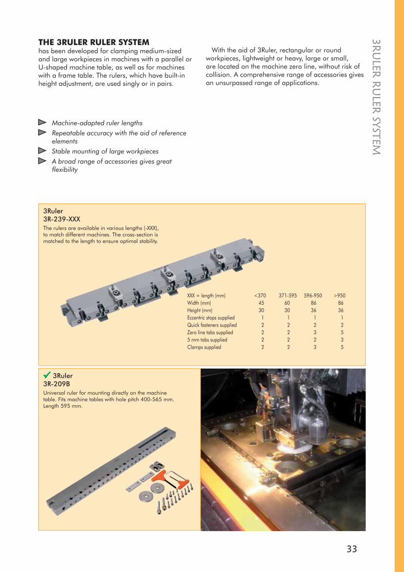
THE 3RULER RULER SYSTEMhas been developed for clamping medium-sized and large workpieces in machines with a parallel or U-shaped machine table, as well as for machines with a frame table. The rulers, which have built-in height adjustment, are used singly or in pairs.
Machine-adapted ruler lengthsRepeatable accuracy with the aid of reference elementsStable mounting of large workpiecesA broad range of accessories gives great flexibility
With the aid of 3Ruler, rectangular or round workpieces, lightweight or heavy, large or small, are located on the machine zero line, without risk of collision. A comprehensive range of accessories gives an unsurpassed range of applications.
3Ruler 3R-239-XXXThe rulers are available in various lengths (-XXX), to match different machines. The cross-section is matched to the length to ensure optimal stability.
XXX = length (mm) <370 371-595 596-950 >950Width (mm) 45 60 86 86Height (mm) 30 30 36 36Eccentric stops supplied 1 1 1 1Quick fasteners supplied 2 2 2 2Zero line tabs supplied 2 2 3 55 mm tabs supplied 2 2 2 3Clamps supplied 2 2 3 5
3Ruler 3R-209BUniversal ruler for mounting directly on the machine table. Fits machine tables with hole pitch 400-565 mm. Length 595 mm.
3RU
LER R
ULER
SYSTEM
34
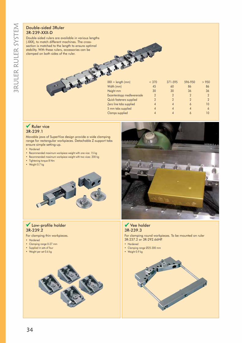
Vee holder3R-239.3For clamping round workpieces. To be mounted on ruler 3R-237.2 or 3R-292.66HP.• Hardened• Clamping range Ø25-300 mm• Weight 0.9 kg
Low-profile holder3R-239.2For clamping thin workpieces.• Hardened• Clamping range 0-27 mm• Supplied in sets of four• Weight per set 0.6 kg
Ruler vice3R-239.1Movable jaws of SuperVice design provide a wide clamping range for rectangular workpieces. Detachable Z-support tabs ensure simple setting-up.• Hardened• Recommended maximum workpiece weight with one vice: 15 kg• Recommended maximum workpiece weight with two vices: 200 kg• Tightening torque 8 Nm• Weight 0.7 kg
XXX = length (mm) < 370 371-595 596-950 > 950 Width (mm) 45 60 86 86Height mm 30 30 36 36Excenterstopp medlevererade 2 2 2 2Quick fasteners supplied 2 2 2 2Zero line tabs supplied 4 4 6 105 mm tabs supplied 4 4 4 6Clamps supplied 4 4 6 10
Double-sided 3Ruler3R-239-XXX-DDouble-sided rulers are available in various lengths (-XXX), to match different machines. The cross-section is matched to the length to ensure optimal stability. With these rulers, accessories can be clamped on both sides of the ruler.
3RU
LER
RU
LER
SYS
TEM
35
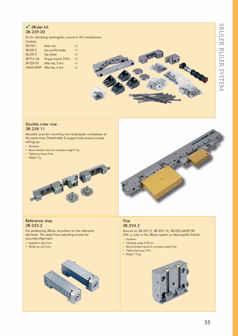
Double ruler vice 3R-239.11Movable jaws for mounting two rectangular workpieces at the same time. Detachable Z-support tabs ensure simplesetting-up.• Hardened• Recommended maximum workpiece weight 7 kg• Tightening torque 8 Nm• Weight 1 kg
3Ruler kit3R-239.20Kit for clamping rectangular, round or thin workpieces.Contents:3R-239.1 Ruler vice x13R-239.2 Low-profile holder x13R-239.3 Vee holder x13R-914-10L Torque wrench, 8 Nm x13R-333-03 Allen key, 3 mm x145600-N039 Allen key, 4 mm x1
Reference stop3R-225.2For positioning 3Ruler anywhere on the referenceelements. The stops have adjusting screws foraccurate alignment.• Supplied in sets of two• Weight per set 0.6 kg
Vice3R-294.2Mounts on 3R-237.2, 3R-292.12, 3R-292.66HP, 3R-294, a ruler in the 3Ruler system or Macropallet 54x54.• Hardened• Clamping range 0-50 mm• Recommended maximum workpiece weight 5 kg• Tightening torque 3 Nm• Weight 1.2 kg
3RU
LER R
ULER
SYSTEM
36
Clamps3R-A239.1Clamps for clamping rulers on reference elements. Supplied in sets of two.
Zero-line support tab 5 mm3R-239.22• Hardened• Recommended maximum workpiece weight per stop 50 kg• Supplied in sets of two.
Miniclamps3R-239.24For clamping thin workpieces. To be fitted together with zero-line support tab.• Recommended maximum workpiece weight per stop 1 kg• Supplied in sets of two.
Clamps3R-A239Clamps of aluminium for mounting a ruler directly on the machine table without reference elements. • Supplied in sets of two, with M8 screw and washers• Weight per set 0.3 kg
Vice3R-294.1For clamping workpieces up to 17 mm. Mounts on 3R-237.2, 3R-292.12, 3R-292.66HP, 3R-294 or a ruler in the 3Ruler system.• Recommended maximum workpiece weight 2.5 kg• Tightening torque 3 Nm• Weight 0.5 kg
Multiple holder3R-294.6For mounting of four workpieces Ø5-13 mm at the same time. Mounts on 3R-237.2, 3R-292.12, 3R-292.66HP, 3R-294 or a ruler in the 3Ruler system.• Tightening torque 3 Nm• Weight 0.6 kg
3RU
LER
RU
LER
SYS
TEM
37
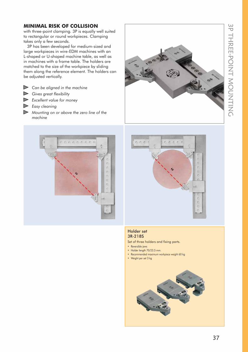
MINIMAL RISK OF COLLISIONwith three-point clamping. 3P is equally well suited to rectangular or round workpieces. Clamping takes only a few seconds.
3P has been developed for medium-sized and large workpieces in wire-EDM machines with an L-shaped or U-shaped machine table, as well as in machines with a frame table. The holders are matched to the size of the workpiece by sliding them along the reference element. The holders can be adjusted vertically.
Holder set3R-218SSet of three holders and fixing parts.• Reversible jaws• Holder length 70/23.5 mm.• Recommended maximum workpiece weight 60 kg• Weight per set 3 kg
Can be aligned in the machineGives great flexibilityExcellent value for moneyEasy cleaningMounting on or above the zero line of the machine
3P THR
EE-POIN
T MO
UN
TING
38
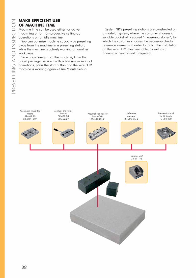
Pneumatic chuck for Macro
3R-602.103R-602.10HP
Manual chuck forMacro
3R-602.203R-602.27
Pneumatic chuck for MacroTwin
3R-602.12HP
Reference element
3R-200.24J-2
Pneumatic chuckfor UnimaticC 950 000
Control unit3R-611.46
MAKE EFFICIENT USEOF MACHINE TIMEMachine time can be used either for active machining or for non-productive setting-up operations on an idle machine.
You can optimise machine capacity by presetting away from the machine in a presetting station, while the machine is actively working on another workpiece.
So – preset away from the machine, lift in the preset package, secure it with a few simple manual operations, press the start button and the wire EDM machine is working again – One Minute Set-up.
System 3R’s presetting stations are constructed on a modular system, where the customer chooses a suitable packet of prepared “measuring stones”, for which the customer chooses the necessary chuck/reference elements in order to match the installation on the wire EDM machine table, as well as a pneumatic control unit if required.
PRES
ETTI
NG
AN
D IN
SPEC
TIO
N

39
PRESET
TING
AN
D IN
SPECTIO
N
Presetting stone3R-228J Stone with three ground faces, a reference element and a clearance stone. Together with a surface plate and a dial indicator, 3R-228J is an excellent presetting tool for a modest outlay.• Dimensions 150x110x80 mm• Weight 5.4 kg
Presetting station3R-228SMounting stone with bushings and holes for mounting chuck/reference elements, as well as a check stone. Use together with existing measuring machine or surface plate and a dial indicator.
Presetting station3R-228.1Surface plate with reference stops, a mounting stone with bushings and holes for mounting a chuck/reference element and through holes for mounting on the surface plate, and a check stone. A dial indicator is required.• Dimensions 500x300 mm
Sine ruler3R-216 With magnetic attachments for setting angles on swivelling elements. Angles are set with gauge blocks.• Measuring length 50 mm• Weight 1.2 kg
Sine ruler Macro3R-216.6For setting angles on swivelling elements. Angles are set with gauge blocks.• Measuring length 50 mm• Weight 1.4 kg
Presetting station X 227 820Surface plate with reference stops, a mounting stone with bushings and holes for mounting a chuck/reference element and through holes for mounting on the surface plate, and a check stone. A dial indicator is required.• Dimensions 800x500 mm

40
PRES
ETTI
NG
AN
D IN
SPEC
TIO
N Master3R-206.10Master for horizontal Macro chucks. One long side ground to the Macro references. Supplied with engraved dimensions in the X-, Y- and Z-directions.• Supplied with drawbar 3R-605.10• For automatic changing, 3R-WP1 must be added.
Master3R-606.2Master for determining the position of vertical Macro chucks. Cylinder ground to the Macro references. Supplied with engraved dimensions in the X-, Y- and Z-directions.• Supplied without drawbar
Reference ball3R-215For finding positions of applications with swivelling elements.• Magnetic attachment for Ø16 mm ball• Supplied with two balls
Actuator3R-611.46 Unit for operation of pneumatic chucks. Three functions – open/neutral/closed.
Wire alignment unit3R-220.3Unit with double-insulated reference contacts for wire alignment.• For Mitsubishi machines• Four wires in the cable• Weight 2.2 kg

41
RO
TATING
SPIND
LES AN
D A
CC
ESSOR
IESREALLY SMALL PARTSthat are difficult to produce in lathes or grinders can usefully be wire-EDMed using a rotating spindle on the machine table.
Rotating spindle3R-6.600-VHSFor clamping in a horizontal Macro chuck. Flushing via the spindle or an external flushing connection.• Control unit included• Drawbar depends on chosen chuck• Rust-resistant• Immersible• Speed range 60-1500 rev/min• Maximum workpiece weight 5 kg• Maximum flushing pressure through the chuck 15 bar• Maximum external flushing pressure 40 bar• Weight 9.5 kg
Rotating spindle3R-6.300-EHS16For clamping in a vertical Macro chuck. Flushing via the spindle or an external flushing connection. Recommended collets – Balzer EHS16, Regofix ER16 or Tecnopinz ETS16.• Control unit included• Drawbar depends on chosen chuck• Rust-resistant• Immersible• Speed range 60-2000 rev/min• Maximum flushing pressure through the chuck 15 bar• Maximum external flushing pressure 40 bar• Weight 10 kg
Support3R-261.1 For mounting directly on the machine table.• Adjustable length 35-135 mm• Recommended maximum workpiece weight 20 kg• Weight 1.5 kg
Adjustable support WEDM3R-261• Adjustable length 38-138 mm• Adjustable height 0-0.2 mm• Recommended maximum workpiece weight 20 kg
Expanding mandrel 3Refix 3R-901-10RSNote: When positioning with 3Refix mandrels – always tighten the expanding mandrel in the R0 hole first.• 3Refix Ø10 mm• Rust-resistant• Recommended tightening torque 4 Nm• Supplied singly• Weight 0.05 kg

42
ICS ZEROLINE TOOLINGis designed for fast, easy and universal use directly on the wire EDM machine table at the zeroline. ICS Zeroline can be mounted and set up very quickly and can be reconfigured or dismantled just as easily and quickly, regardless of whether it is designed as a clamping support, levelling head or clamping bar.
The ICS Zeroline range also features adapter elements allowing the user to use the entire range of ICS and Unimatic clamping elements for direct table mounting.
ADAPTERS AND ADAPTATIONELEMENTSallow the user to utilise the entire diversity and all the strengths of the 3R clamping elements on his or her machine configuration.
Manual ICS and Unimatic adapters offer the option of mounting the clamping elements directly on Zeroline tables and nevertheless utilising the advantage of the levelling head.
OVERVIEW ICS ZEROLINE SYSTEM
Clamping bars / Mecarail
Adapter
Unimatic clamping elements
Clampingsupports
Levelling heads
ICS clamping elements
BASI
C E
QU
IPM
ENT
ICS

43
90 50
300 5
486
80
30
-3,500
+40
4x M8
26
100130
X = 22-100 mm
486
180 5
87,5
75
26
20
(B)12 (C)22
+4
-3,50 0 0
50
9
2x M8
26
90
30
X= 22-100 mm
3x M8
ICS Zeroline clamping support 300C 666 020Clamping support for the direct installation on WEDM machine table.• Support lips „+4“ and „0“• Recommended maximum workpiece weight 50 kg in application
as support element• Weight 5.3 kg
ICS Zeroline clamping support 180C 666 040Clamping support for the direct installation on WEDM machine table.• Support lips „+4“ and „0“• ICS adaptation B&C for the installation of ICS clamps & holders• Recommended maximum workpiece weight 50 kg in application
as support element• Weight 3.1 kg
ICS ZER
OLIN
E
Set ICS Zeroline MiniS 150 500consisting of:C 666 020 Clamping support 300 x1C 666 040 Clamping support 180 x1N 150 000 Support lips ’’+4’’ x4C 666 022 Support lips ’’0’’ x4S 150 350 Set screws/prolongations M8 x1N 153 010 Bushings M8 (inkl. screws) x6N 153 020 Bushings M6 (inkl. screws) x6E 100 007 Set hexagon Allen wrench x1Set packed in case
Set ICS Zeroline Go!S 150 550consisting of:C 666 020 Clamping support 300 x1C 666 040 Clamping support 180 x1C 642 050 Flange 26/200 x1N 150 000 Support lips ’’+4’’ x4C 666 022 Support lips ’’0’’ x4S 150 350 Set screws/prolongations M8 x1N 153 010 Bushings M8 x6E 100 007 Set hexagon Allen wrench x1Set packed in case
Set AC Vertex1S 150 560consisting of:C 666 060 Clamping support 155 x1C 557 300 Vertex 1 clamping bar x1C 666 022 Support lips ’’0’’ x4 Set screws/prolongations M8 x1E 100 007 Set hexagon Allen wrench x1Set packed in case

44
50
60
12
7
16
26
20 15
8022
90
180
4 4
ICS Adaption A
ICS Adaption B
50
30
16712
120
55
22 8026
20 15
4
4
ICS Adaption AICS Adaption B
95
35
28
45
35
81
20
M8
4
4 M8
4
4
150
90
30
3120
36
5026
20
22
(B)
124
109
120
200
M8
250
5
260
150
102
51
5050
27 2754 54 145
105 0
22 12
18
M8
26
20 20
26
32
26
50
4
3,5
M6
M8
M6
M8
ICS Zeroline adapter A/BC 665 700Basic element for the adaptation of ICS clamping elements of the series A and B.• Functional height: clamping of workpiece on Z = “+4“ mm and Z = “0“• Adaptation height ICS A: 7 mm / ICS B: 12 mm • Weight 1.5 kg
ICS Zeroline adapter A/B shortC 665 720Basic element for the adaptation of ICS clamping elements of the series A and B.• Functional height: clamping of workpiece on Z = “+4“ mm and Z = “0“• Adaptation height ICS A: 7 mm / ICS B: 12 mm • Weight 1.1 kg
ICS Zeroline clamp 90C 552 630Clamping support for the direct installation on WEDM machine table.• Functional height: clamping of workpiece on Z = “0“• Recommended maximum workpiece weight 20 kg in application
as support element• Weight 0.25 kg
ICS Zeroline clamp 150C 552 640Clamping support for the direct installation on WEDM machine table.• Functional height: clamping of workpiece on Z = “+4“ mm• Recommended maximum workpiece weight 20 kg in application
as support element• Weight 0.5 kg
ICS Zeroline adapter BC 665 900Clamping support for the direct installation on WEDM machine table.• Functional height: clamping of workpiece on Z = “+4“ mm and Z = “0“• Recommended maximum workpiece weight 20 kg in application
as support element• Weight 0.5 kg
ICS Zeroline multi-adapter 250C 665 600Clamping support for the direct installation on WEDM machine table.• Support lips „+4“ and „0“• ICS adaptation B&C for the installation of ICS clamps & holders• Recommended maximum workpiece weight 75 kg in application
as support element• Weight 5.3 kgIC
S ZE
RO
LIN
E

45
ICS ZER
OLIN
EICS ZEROLINE MECARAIL AND ICSZEROLINE CLAMPING BARSare available in various sizes, matched to the wire EDM machine tables.
The brackets and screws required for attachment on the machine table are included in the scope of delivery.
Please use the selection table on our website (www.system3r.com) to determine the ICS Zeroline Mecarail or ICS Zeroline clamping bars specific to your machine or state the make of machine and type when ordering.
ICS Zeroline clamping bar C 557 XXXSingle sided clamping bar, including brackets.
Length < 570 571 - 750 > 750
Width 70 70 70
Height 30 35 40
Length < 380 < 480 <680 < 750
Number of lips/brackets 2 3 4 6
ICS Zeroline Mecarail C 558 XXXDouble sided clamping bar, including brackets.
Length < 570 571 - 750 > 750
Width 70 75 75
Height 30 35 40
Length < 380 < 480 <680 < 750
Number of lips/brackets 2 3 4 6
Set ICS Zeroline MaxiS 206 4XX* When ordering, please state the machine type as well as X or Y axes.consisting of:C 558 0xx Standard Mecarail * 1xS 150 000 Set Mecarail-Vice 1xS 150 310 Set base plates ’’+4’’ 1xE 100 007 Set hexagon Allen wrench 1xSet packed in case (Mecarail in carton)

46
ICS ClampC 552 620The main application of the ICS clamp is fixing small workpieces of different dimensions.• Functional height workpiece on „0 mm“, with intermediate plate "+4"• Clamping range 0 – 10 mm • Maximum workpiece weight 3 kg, not for overhung clamping! • Adaptation to all ICS C 557 xxx • Dimensions 80 x 28 mm• Weight 0.2 kg
Mecarail Clamp ”+4”C 552 600The main application of the ICS clamp is fixing workpieces of different dimensions.• Functional height workpiece
on „+4 mm“ • Clamping range 0 – 20 mm • Maximum workpiece weight 6 kg, not for overhung clamping! • Adaptation to all Mecarail C 558 xxx • Dimensions 40 x 55 x 30 mm• Weight 0.2 kg
Mecarail Clamp ”0”C 552 610The main application of the ICS clamp is fixing workpieces of different dimensions.• Functional height workpiece on „0 mm“ • Clamping range 0 – 20 mm • Maximum workpiece weight 6 kg, not for overhung clamping! • Adaptation to all Mecarail C 558 xxx • Dimensions 40 x 55 x 34 mm• Weight 0.2 kg
Mecarail ViceS 150 000Jaw set for Mecarail; with guide; for horizontal parallel clamping.• Functional height 30 mm • Maximum workpiece weight 15 kg • Maximum workpiece dimensions
100 x 120 x 160 mm • Adaptation to all Mecarail C 558 xxx • Overall height 30 mm • Weight 0.8 kg
Mecarail TwinviceS 149 900Twin-Jaw set for Mecarail; with guide; for horizontal parallel clamping.• Functional height 30 mm • Maximum workpiece weight 15 kg • Maximum workpiece dimensions
100 x 120 x 160 mm • Adaptation to all Mecarail C 558 xxx • Overall height 30 mm• Weight 1.2 kg
Mecarail V-blockC 597 560Workpiece carrier for round parts; for the use on Mecarail.• Functional height 30 mm • Clamping range Ø20 – 150 mm• Maximum workpiece weight 15 kg • Maximum workpiece dimensions
Ø150 x 100 mm • Adaptation to all Mecarail C 558 xxx• Dimensions 210 x 53 mm• Weight 2.8 kg
Set base plates ”+4”
S 150 3104 mm baseplates for collision-free clamping of workpieces on Mecarails and clamping bars.• Weight 0.2 kg
ICS Adaptation A, B or CAdapter to ICS Zeroline clamping bar C 557 xxx and ICS Zeroline Mecarail C 558 xxx for the adaptation of ICS clamping elements • Weight approx. 0.7 kg
C 456 650• Adaptation to all clamping elements ICS A • Adaptation height 7 mm (ICS A)
C 456 660• Adaptation to all clamping elements ICS B • Adaptation height 12 mm (ICS B)
C 456 670• Adaptation to all clamping elements ICS C• Adaptation height 22 mm (ICS C)
ICS
ZER
OLI
NE
47
40
170
135
100
2020
M8 M6
80
46
2323
23
90
18 18 18 18
90
16,5
17 8
170
37,5
M8
24,5
12,5
33
125
4xM6
4x für M6
180
8559
56,3
16
86
45
4x M8
87,55
ICS ZER
OLIN
E
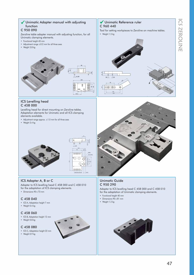
Unimatic Reference rulerC 960 440Tool for setting workpieces to Zeroline on machine tables.• Weight 1.5 kg
ICS Levelling headC 458 000Levelling head for direct mounting on Zeroline tables.Adaptation elements for Unimatic and all ICS clamping elements available.• Adjustment range approx. ±1.0 mm for all three axes• Weight 3.4 kg
Unimatic Adapter manual with adjusting function
C 950 090Zeroline table adapter manual with adjusting function, for all Unimatic clamping elements.• Functional height 45 mm• Adjustment range ±0.2 mm for all three axes• Weight 3.8 kg
ICS Adapter A, B or CAdapter to ICS levelling head C 458 000 and C 458 010 for the adaptation of ICS clamping elements.• Dimensions 90 x 73 mm
C 458 040• ICS A, Adaptation height 7 mm • Weight 0.4 kg
C 458 060• ICS B, Adaptation height 12 mm • Weight 0.8 kg
C 458 080• ICS C, Adaptation height 22 mm • Weight 0.9 kg
Unimatic GuideC 950 290Adapter to ICS levelling head C 458 000 and C 458 010for the adaptation of Unimatic clamping elements.• Functional height 40 mm • Dimensions 90 x 81 mm• Weight 1.2 kg
48
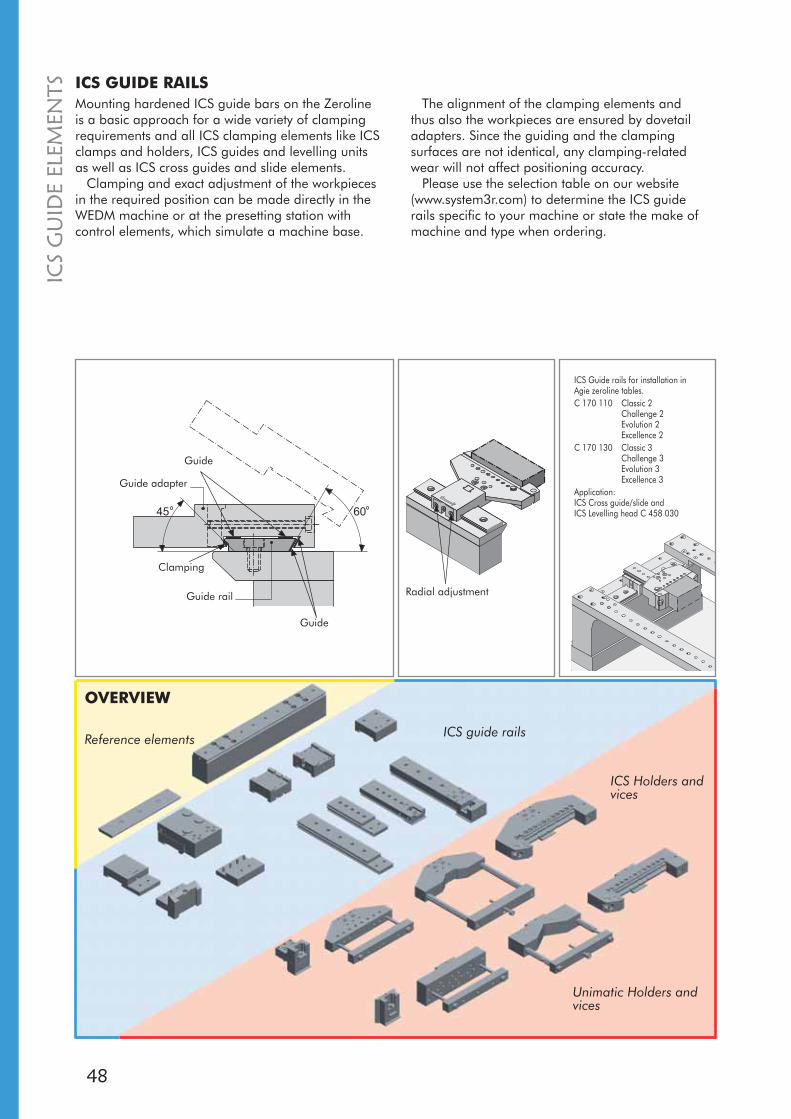
6045
Mounting hardened ICS guide bars on the Zeroline is a basic approach for a wide variety of clamping requirements and all ICS clamping elements like ICS clamps and holders, ICS guides and levelling units as well as ICS cross guides and slide elements.
Clamping and exact adjustment of the workpieces in the required position can be made directly in the WEDM machine or at the presetting station with control elements, which simulate a machine base.
The alignment of the clamping elements and thus also the workpieces are ensured by dovetail adapters. Since the guiding and the clamping surfaces are not identical, any clamping-related wear will not affect positioning accuracy.
Please use the selection table on our website (www.system3r.com) to determine the ICS guide rails specific to your machine or state the make of machine and type when ordering.
ICS GUIDE RAILS
Radial adjustment
Guide
Guide rail
Guide
Clamping
ICS Guide rails for installation in Agie zeroline tables.C 170 110 Classic 2
Challenge 2Evolution 2Excellence 2
C 170 130 Classic 3Challenge 3Evolution 3Excellence 3
Application:ICS Cross guide/slide and ICS Levelling head C 458 030
Guide adapter
ICS
GU
IDE
ELEM
ENTS
OVERVIEW
Reference elements ICS guide rails
ICS Holders and vices
Unimatic Holders and vices

49
46
2323
23
90
16,5
17 8
53,5
30
32
125
6
12,5
63,5
25
4xM6
4x für/for M6
C 170 000 230 50 - M8 x5
C 170 050 230 50 5 M8 x5
C 170 110 280 40 - M8 x7
C 170 130 380 42,5 - M8 x9
C 170 150 220 25 - M8 x9
C 170 200 220 25 5 M8 x9
C 170 300 350 50 - M8 x7
C 170 600 350 50 5 M8 x7
C 170 650 120 25 - M8 x4
C 170 750 410 50 5 M8 x7
C 170 760 288 50 5 M8 x6
C 170 770 348 50 2 M8 x7
C 170 800 320 50 5 M8 x6
C 170 840 298 50 4 M8 x6
C 170 850 320 50 7.5 M8 x6
C 170 950 338 50 5 M8 x7
ICS
GU
IDE ELEM
ENTS
Unimatic guideC 950 290Adapter to ICS levelling head C 458 000 and C 458 010for the adaptation of Unimatic clamping elements. • Functional height 40 mm • Dimensions 90 x 81 mm• Weight 1.2 kg
ICS Levelling headC 458 010Levelling head for the use on ICS guide rails. Adaptation elements for Unimatic and all ICS clamping elements available.• Functional height 55.5 mm • Adjustment range approx. ±1.0 mm for all three axes• Weight 3.4 kg
ICS Adapter A, B or CAdapter to ICS levelling head C 458 000 and C 458 010 for the adaptation of ICS clamping elements.• Dimensions 90 x 73 mm
C 458 040• ICS A, adaptation height 7 mm • Weight 0.4 kg
C 458 060• ICS B, adaptation height 12 mm • Weight 0.8 kg
C 458 080• ICS C, adaptation height 22 mm • Weight 0.9 kg
ICS Guide adapter A, B or CAdapter with ICS adaptation for the use on ICS guide rails.
C 456 250• ICS A (7/70)• Functional height 7 mm • Weight 1.1 kg
C 456 350• ICS B (12/70)• Functional height 12 mm • Weight 1.3 kg
C 456 450• ICS C (22/70)• Functional height 22 mm • Weight 1.5 kg
ICS Guide railC 170 XXXGuide element for the installation of ICS elements like ICS guide adapter and ICS levelling head.• Dimensions 48.5 x 8 mm • Weight depending on the length, approx. 0.26 kg/100 mm
Item no. L A B S
guide side

50
2234
70
70
34
70
7022
13
50
164
7
15
445x20=100
8,5
22
39,4
M5
1226
22
50
156
4x20=80 56
209
M8
26
22
50
4x20=80
9 20
56
156
22
M8
22
274
26
20
744x40=160
12
9
50
M8
ICS GUIDE ELEMENTSThe time-proven ICS guide system, with the guide elements, offers various options for clamping workpieces in various positions.
The ICS guide elements are the connecting elements between the ICS beam and the ICS slides and the ICS slide clamping elements.
The ICS slides are the supports for the ICS clamping elements whose adapter faces are matched to series A, B and C.
The ground stop faces ensure a rectangular position of the bolted-on clamping elements.
ICS Cross guideC 300 050The connecting link between the ICS guide rail / ICS beam and the standard slide or the supporting clamping elements.
Note: the outer faces of C 300 500 are ground at right angles to be used with limit stops.• Functional height 22 mm • Weight 0.9 kg
ICS Cross guide universalC 300 100The connecting link between the ICS guide rail / ICS beam and the standard slide or the supporting clamping elements.
Note: the outer faces of C 300 100 are ground at right angles. The two adjusting screws allow radial adjustment.• Functional height 22 mm • Weight 0.9 kg
ICS Slide AN 460 700Support for the ICS clamping elements series A.• Adaptation height 7 mm • Weight 0.6 kg
ICS Slide BN 460 100Support for the ICS clamping elements series B.• Adaptation height 12 mm • Weight 1.0 kg
ICS Slide CN 460 300Support for the ICS clamping elements series C.• Adaptation height 22 mm • Weight 1.2 kg
ICS Slide B (12/22)N 460 000Support for the ICS clamping elements series B.• Functional height 12 mm • Weight 1.9 kg
ICS Support ”+4”
N 150 050The ICS support “+4” can be fitted between the ICS slides B and C and clamping elements for collision-free clamping.
ICS
GU
IDE
ELEM
ENTS

51
126
12
50
18174
4 3
5022 26
144
174
4
564x20=80
25
8,5
50
3x40=120 120
4
4 3430
4
274
9
430
50
3x40=120
274
9925
4
4
34
9
304
50
99
274
3x40=120
4
4
25 34
9
ICS
GU
IDE ELEM
ENTS
ICS SLIDE CLAMPING ELEMENTSThe main application of the ICS slide clamps is fixing workpieces of different dimensions in position from two sides.
Recommendation:Work with opposite elements wherever possible.
ICS Slide clamp 30C 551 300The main application of the ICS clamp is fixing workpieces of different dimensions in position from two sides.• Functional height 30 mm • Weight 3.0 kg
ICS Slide clamp 30 leftC 552 100The main application of the ICS clamp is fixing workpieces of different dimensions in position from two sides.• Functional height 30 mm • Weight 3.0 kg
ICS Slide clamp 26C 550 900The main application of the ICS clamp is fixing workpieces of different dimensions in position from two sides.• Functional height 26 mm • Weight 1.3 kg
ICS Slide clamp 30 rightC 551 700The main application of the ICS clamp is fixing workpieces of different dimensions in position from two sides.• Functional height 30 mm • Weight 3.0 kg
ICS Slide clamp 12C 550 500The main application of the ICS clamp is fixing workpieces of different dimensions in position from two sides.• Functional height 12 mm • Weight 0.9 kg
52
40
40
180
5555
100
80
30
76,511
0,5
4x M8
12
120
83
100
40
14 50
14 40
M8
4x M8
28 22
70
70
40
40
M8
29 23
30
45
90
90
TK-. 48
45
TK- 84 12x M6
TK- 80
30
38
44
90
90
30
45
48
45
84
80
30
12x M6
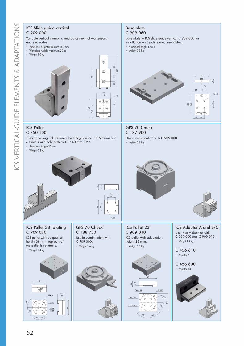
ICS Slide guide verticalC 909 000Variable vertical clamping and adjustment of workpieces and electrodes.• Functional height maximum 180 mm• Workpiece weight maximum 20 kg• Weight 5.0 kg
Base plateC 909 060Base plate to ICS slide guide vertical C 909 000 for installation on Zeroline machine tables.• Functional height 12 mm• Weight 0.9 kg
ICS PalletC 350 100The connecting link between the ICS guide rail / ICS beam and elements with hole pattern 40 / 40 mm / M8.• Functional height 22 mm • Weight 0.8 kg
GPS 70 ChuckC 187 900Use in combination with C 909 000.• Weight 2.5 kg
GPS 70 ChuckC 188 750Use in combination with C 909 000.• Weight 1.6 kg
ICS Pallet 23C 909 010ICS pallet with adaptation height 23 mm.• Weight 0.8 kg
ICS Pallet 38 rotatingC 909 020ICS pallet with adaptation height 38 mm, top part of the pallet is rotatable.• Weight 1.4 kg
ICS Adapter A and B/CUse in combination with C 909 000 und C 909 010.• Weight 1.4 kg
C 456 610• Adapter A
C 456 600• Adapter B/C
ICS
VER
TIC
AL-
GU
IDE
ELEM
ENTS
& A
DA
PTAT
ION
S

53
UNIMATIC PALLET SYSTEMReducing setting times and optimising productive times and doing all this with no reduction in machining quality are crucial criteria for ensuring competitiveness.
One promising approach is certainly to enhance flexibility by using pallet systems, specifically universal systems, allowing a fast, flexible response to customer requirements.
It is precisely these demands that are met by the Unimatic Pallet System.
UN
IMATIC
OVERVIEW OF THE UNIMATIC SYSTEM
Unimatic chucks
Adapter
Unimatic clamping elements
Unimatic pallets
ICS clamping elements

54
28
90
86
43,5
81
10
5,5
100 100
220
86
100
50
2510
202
12,5
119
28
43,5
for M8
M8
PE
C
Unimatic ChuckC 950 000Manual and automatic palletizing of work carriers.• Functional height 28 mm • Clamping force 5000 N• Weight 1.9 kg
Unimatic Twin ChuckC 950 070Manual and automatic palletizing of work carriers with workpieces >25 kg.• Functional height 28 mm • Clamping force 10000 N• Weight 2.8 kg
Clamping mechanically with pneumatic release provides maximum operational safety and reliability. The functions of the compressed air ports are as follows:
P = releasing / clampingE = ventilationC = support cleaning / presence check
Unimatic clamping function
Preclamping 0.1 mm
UNIMATIC CHUCKis the basic element for manual or automatic feed to the wire EDM machine with palletised workpieces
Axial suspension of the X/Y-centring cams in the chuck and ground centering prism in the pallets, ensures maximum repeat and transmission accuracyUnchanging positioning accuracy and high stability even when strong flushing pressure
3-AXIS ADJUSTMENTThe workpieces clamped in the clamping elements can be accommodated directly in an adjusting or levelling pallet without further adapters.
This allows the adjustment and levelling movements and vertical adjustability to be utilised directlyUnsupported clamping of workpieces weighing up to 25 kg with a repeat accuracy of ± 0.002 mm and a projection of 160 mm
COMPRESSED-AIR ACTUATIONPressure 6 bar minimumPressure 10 bar maximumCompressed-air quality: 40 μm filtered, dry and de-oiled
UN
IMAT
IC

55
63,5
9026
,5
57,5
115,5
7 63,5 7
26,557
,5
115,5
90
Unimatic BracketsC 950 0XXThe Unimatic brackets for mounting the chuck C 950 000 on the zeroline table are machine-dependent.
Note: Please use the selection tables on our webpage (www.system3r.com) to determine the appropriate Unimatic bracket or state the make of machine and type when ordering.
Set Unizero Go2!S 112 060consisting of:C 950 000 Unimatic Chuck x1C 950 170 Unimatic Adjusting pallet x1C 960 040 Unimatic V-block flange 30/200 x1C 190 820 Air-pistol valve x1E 100 007 Set hexagon Allen wrench x1C 950 0xx Unimatic Brackets* x1Set packed in case* When ordering, please state the machine type
to allow us to determine the Unimatic brackets.
Set Unimatic Basic equipmentS 206 301consisting of:C 950 000 Unimatic Chuck x1C 960 500 Unimatic Control unit x1C 960 710 Unimatic Protection pallet x1C 950 0XX Unimatic Bracket* x1* When ordering, please state the machine type to allow us to determine the Unimatic brackets.
Unimatic Levelling palletC 950 150Levelling pallet with dovetail guide adaptation.• Adjustment range approx. ±1.0 mm for all three axes• Functional height 59 mm, Unimatic pallet placed onto Unimatic chuck • Weight 2.5 kg
C 951 150• Ready for use for automation with assembled code tag and pins.
Unimatic Adjusting palletC 950 170Adjusting pallet with dovetail guide adaptation.• Adjustment range ±0.2 mm for all three axes• Functional height 59 mm, Unimatic pallet placed onto Unimatic chuck • Weight 2.5 kg
C 951 170• Ready for use for automation with assembled code tag and pins.
UN
IMATIC
CO
NTR
OL ELEM
ENTS
Set Unizero Go!S 112 050consisting of:C 950 000 Unimatic Chuck x1C 950 170 Unimatic Adjusting pallet x1C 960 110 Unimatic Vice 10-30 x1C 190 820 Air-pistol valve x1E 100 007 Set hexagon Allen wrench x1C 950 0xx Unimatic Brackets* x1Set packed in case* When ordering, please state the machine type
to allow us to determine the Unimatic brackets.

56
26
20
66
151
90
58
2831
1
40
11
M8
2831
11
1
66 40
58
151
26
20
90
M8
40 90
90
40
18
5,555 25
8
4x M6x10 M5x8
4x M8x14
27,5
1579
47,5
(A)
21
30
M8
90
139
22
26
84 20
149
40
90
(C)
6
27,547
,5
M8
26
84 20
149
47,5
40
(B)
16
27,5
90
M8
Unimatic Levelling pallet ICS BC 950 180Levelling pallet with ICS B adaptation.• Adjustment range approx. ±1.0 mm for all three axes• Functional height 59 mm, Unimatic pallet placed onto Unimatic chuck • Adaptation height 12 mm• Weight 2.5 kg
C 951 180• Ready for use for automation with assembled code tag and pins.
Unimatic Adjusting pallet ICS BC 950 190Adjusting pallet with ICS B adaptation.• Adjustment range ±0.2 mm for all three axes• Functional height 59 mm, Unimatic pallet placed onto Unimatic chuck • Adaptation height 12 mm• Weight 2.5 kg
C 951 190• Ready for use for automation with assembled code tag and pins.
Unimatic PalletC 950 100Pallet used as fixture carrier.• The overall height of the Unimatic chuck C 950 000 together with the
Unimatic pallet C 950 100 is 46 mm • Functional height 18 mm • Weight 0.9 kg
C 951 100• Ready for use for automation with assembled code tag and pins.
Unimatic Pallet AC 950 120Support for ICS clamping elements series A. • Functional height 21 mm (A)• Adaptation height 7 mm• Weight 1.6 kg
C 951 120• Ready for use for automation with assembled code tag and pins.
Unimatic Pallet BC 950 130Support for ICS clamping elements series B. • Functional height 16 mm (B)• Adaptation height 12 mm• Weight 1.9 kg
C 951 130• Ready for use for automation with assembled code tag and pins.
Unimatic Pallet CC 950 140Support for ICS clamping elements series C.• Functional height 6 mm (C)• Adaptation height 22 mm• Weight 2.0 kg
C 951 140• Ready for use for automation with assembled code tag and pins.
UN
IMAT
IC P
ALL
ETS
57
290
220
200
146
146
28
-440
53
114
389
30
20
M8/M6
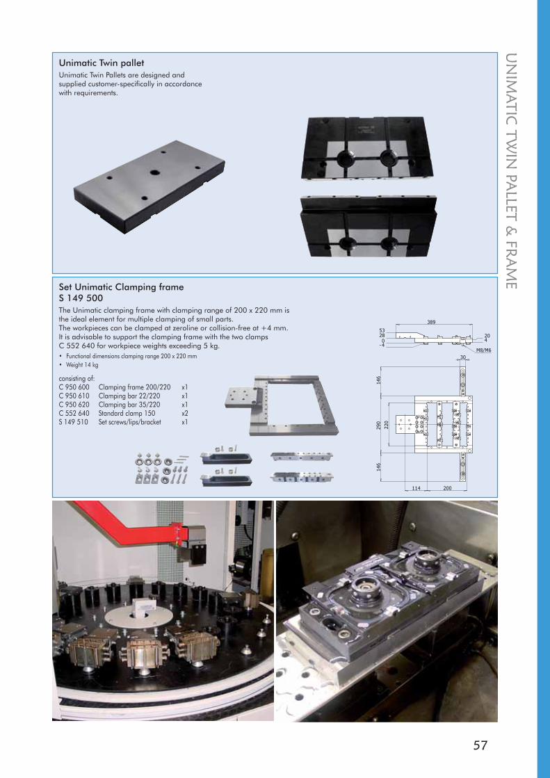
Set Unimatic Clamping frameS 149 500The Unimatic clamping frame with clamping range of 200 x 220 mm is the ideal element for multiple clamping of small parts. The workpieces can be clamped at zeroline or collision-free at +4 mm. It is advisable to support the clamping frame with the two clamps C 552 640 for workpiece weights exceeding 5 kg.• Functional dimensions clamping range 200 x 220 mm• Weight 14 kg
consisting of:C 950 600 Clamping frame 200/220 x1C 950 610 Clamping bar 22/220 x1C 950 620 Clamping bar 35/220 x1C 552 640 Standard clamp 150 x2S 149 510 Set screws/lips/bracket x1
Unimatic Twin palletUnimatic Twin Pallets are designed and supplied customer-specifically in accordance with requirements.
UN
IMATIC
TWIN
PALLET &
FRA
ME

58
90
90
20,2
P1P2
P2
P1
EC
IN
PUP3
90 60
30
38
18
90
215
160
10
Unimatic Protection palletC 960 710Protection of ball cage and X/Y-reference elements of the Unimatic chuck.• Functional height 20 mm• Weight 0.4 kg
Unimatic Control unit (1-fold)C 960 500Pneumatic control for Unimatic chuck.• Weight 0.4 kg
Unimatic Control unit (2-fold)S 190 520Individual actuation of two Unimatic chucks.• Weight 4.2 kg
Unimatic Reference pallet C 960 450Measuring and inspection element.• Functional height 18 mm• Indexing 4 x 90° • Accuracy repetition 0.001 mm / transfer ±0.002 mm on 160 mm • Positioning of reference hole 160 ±0.002 mm to pallet centre • Weight 2.7 kg
Unimatic Force checking unit C 960 430Force checking on the Unimatic chuck.• Weight 0.7 kg
Set Unimatic RevisionS 190 900Wear parts set for Unimatic chucks C 950 000 and C 950 070.
UN
IMAT
IC A
CC
ESSO
RIE
S

59
2
Z
Y
A
1
4
3
4
32
1
B
Z
Y
ICS CLAMPING ELEMENTSThe diverse range of clamping elements included in the two ICS and Unimatic product lines offer an optimum solution for virtually any clamping problem.
The corresponding adapters allow the user to freely combine ICS, Unimatic and also System 3R clamping elements and clamping systems.
ICS A, B AND CThe right clamping element for every large workpiece.
Series A / for small workpieces up to 3 kgSeries B / for medium-size workpieces up to 10 kgSeries C / for large workpieces over 10 kg
Adjusting screws can be used to adjust in the range of 0.05 mm on all ICS clamping elements.
Correction, Line ATightening 1 and 2 corrects line A in direction Z shown by the arrow.
Tightening 3 and 4 corrects line A in direction Y shown by the arrow..
Correction, Line BTightening 2 and 4 corrects line B in direction Z shown by the arrow.
Tightening 1 and 3 corrects line B in direction Y shown by the arrow.
ICS
CLA
MPIN
G ELEM
ENTS
60
7
4
441
75
50
22
M5
17
7013
46
7M5
95,8
30
22
4610
713
M5
118
22
30
0-75
16
76
44
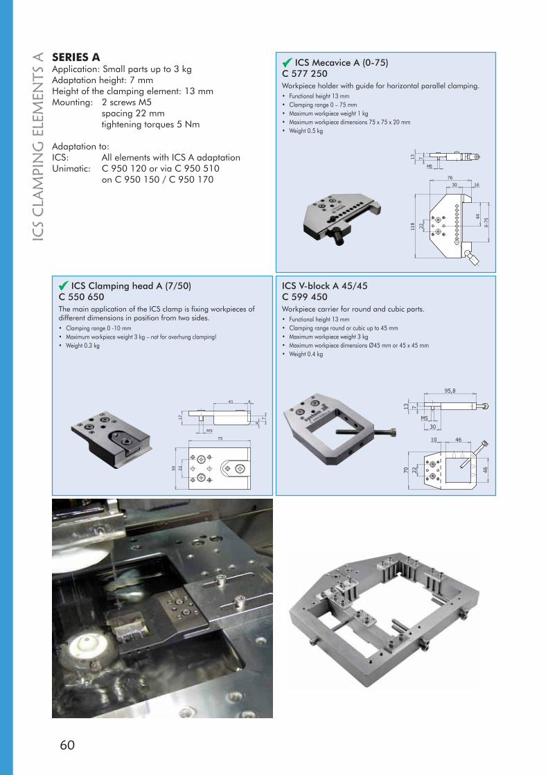
ICS Clamping head A (7/50)C 550 650The main application of the ICS clamp is fixing workpieces of different dimensions in position from two sides.• Clamping range 0 -10 mm • Maximum workpiece weight 3 kg – not for overhung clamping!• Weight 0.3 kg
ICS V-block A 45/45C 599 450Workpiece carrier for round and cubic parts.• Functional height 13 mm • Clamping range round or cubic up to 45 mm • Maximum workpiece weight 3 kg • Maximum workpiece dimensions Ø45 mm or 45 x 45 mm • Weight 0.4 kg
ICS Mecavice A (0-75)C 577 250Workpiece holder with guide for horizontal parallel clamping.• Functional height 13 mm• Clamping range 0 – 75 mm • Maximum workpiece weight 1 kg • Maximum workpiece dimensions 75 x 75 x 20 mm• Weight 0.5 kg
SERIES AApplication: Small parts up to 3 kgAdaptation height: 7 mmHeight of the clamping element: 13 mmMounting: 2 screws M5
spacing 22 mmtightening torques 5 Nm
Adaptation to:ICS: All elements with ICS A adaptation Unimatic: C 950 120 or via C 950 510
on C 950 150 / C 950 170
ICS
CLA
MPI
NG
ELE
MEN
TS A

61
4
4
M 5
1130 41
80 22 45
17
75
30100
4020
80 22 45
304,5
14,5
9,530
20
713
6,547
M8
120
22
60
M5
10
713 7
30
13
-3,9
7
145,8
116
82
82
5
5
4
9
0
88
81
145
3,90
13
70
9
ICS
CLA
MPIN
G ELEM
ENTS A
ICS Double clamp A (5/80)C 550 670Clamp for holding thin plates with support lips at zero height. A 4 mm thin shim can be inserted between the adaptation faces for collision free clamping.• Clamping range 0 - 5 mm • Maximum workpiece weight 1 kg - overhung clamping • Weight 0.4 kg
ICS Side clamp A (20-40)C 577 200Collateral clamping of rectangular or square small workpieces from 20 to 40 mm width.• Functional height 6,5 mm • Clamping range 20 - 40 mm • Maximum workpiece weight 0.5 kg • Weight 0.5 kg
ICS Flange A (7/120)C 641 900Support for the lateral mounting of workpiece.• Functional height 7 mm • Maximum workpiece weight 1 kg • Maximum workpiece dimensions width 100 mm max. • Weight 0.5 kg
ICS Clamping frame AC 619 660Carrier for flat round or cubic workpieces up to 80x80 mm.• Functional height 13 mm • Clamping range round or cubic up to 80 mm /
maximum workpiece height 12 mm• Maximum workpiece weight 1.5 kg • Maximum workpiece dimensions Ø 80 mm or 80x80 mm• Weight 0.9 kg
ICS Clamping bar to clamping frame AC 619 670Clamping bar to use with ICS clamping frame A C 619 660.• Dimensions 88 x 20 x 26 mm • Overall height 26 mm (incl. support lips and clamping lips) • Weight 0.25 kg

62
12
4
26 8
504
4
26
4
91
M8
70
266
6
1222 26
45221226
670
26
6
45
ICS Clamping head B (12/50)C 552 300The main application of the ICS clamp is fixing workpieces of different dimensions.• Clamping range 0 - 20 mm • Maximum workpiece weight 10 kg – not for overhung clamping! • Weight 0.5 kg
SERIES BApplication: Medium-sized workpieces up to 10 kgAdaptation height: 12 mmMounting: 2 screws M8
spacing 26 mmtightening torques 20 Nm
Adaptation to:ICS: All elements with ICS B adaptation Unimatic: C 950 130 or
via C 950 530 on C 950 150 / C 950 170 and C 950 180 / C 950 190
ICS Clamping head B right (12/50)C 552 400The main application of the ICS clamp is fixing workpieces of different dimensions.• Clamping range 0 - 20 mm • Maximum workpiece weight 10 kg – not for overhung clamping! • Weight 0.5 kg
ICS Clamping head B left (12/50)C 552 500The main application of the ICS clamp is fixing workpieces of different dimensions.• Clamping range 0 - 20 mm • Maximum workpiece weight 10 kg – not for overhung clamping! • Weight 0.5 kg
ICS
CLA
MPI
NG
ELE
MEN
TS B

63
12
2326
M8
25
50
69
4
26
(B)
12
4
25 5
26
50
38
70
X
X = 10-30 mm
M8
35
122221
0
26 150
25
2535
100
M8
0-17
5 m
m45
40
260
35
26
M8 4512
120
30
5
22,5
4743
30
22,5
30
ICS
CLA
MPIN
G ELEM
ENTS B
ICS Vice B 0-20C 573 550Workpiece carrier with guide for vertical parallel clamping, with 2 clamping jaws.• Functional height 20 mm • Clamping range 0 - 20 mm • Maximum workpiece weight 1 kg • Maximum workpiece dimensions 20 x 50 x 50 mm • Weight 0.4 kg
ICS Vice B 10-30C 574 150Workpiece carrier with guide for vertical parallel clamping.• Functional height 30 mm • Clamping range 0 - 30 mm • Maximum workpiece weight 3 kg • Maximum workpiece dimensions 30 x 90 x 90 mm • Weight 0.6 kg
ICS Mecavice B 0-150C 577 350Workpiece holder with guide for horizontal parallel clamping.• Functional height 22 mm • Clamping range 0 – 150 mm • Maximum workpiece weight 4 kg • Maximum workpiece dimensions 150 x 120 x 22 mm • Weight 1.6 kg
ICS Mecavice B 0-175C 577 370Workpiece holder with guide for horizontal parallel clamping.• Functional height 30 mm • Clamping range 0 – 175 mm • Maximum workpiece weight 10 kg • Maximum workpiece dimensions 100 x 120 x 175 mm • Weight 3.7 kg
Vice jaw setS 150 100Jaw set for Mecavice B and Unimatic vice with guide for horizontal parallel clamping.• Functional height 30 mm • Clamping depth jaw 18 mm • Maximum workpiece weight 5 kg • Weight 0.4 kg
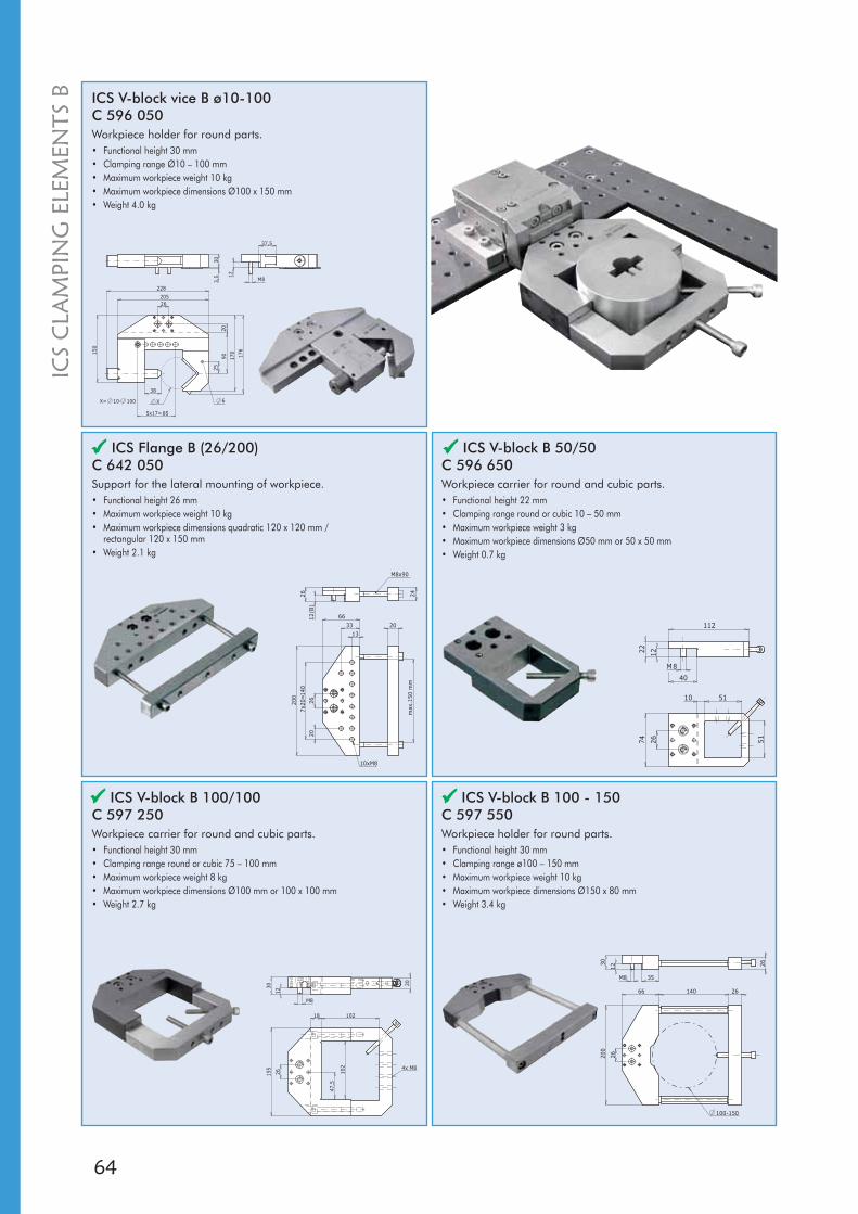
64
12
303,
5
X
205
228
150
176
170
2090
25
26
M8
5x17=85
38
37,5
X= 10- 100 6
12
30 20
155
26 102
102
M8
47,5
18
4x M8
3020
0
66 26
26
140
12
M8 35
26
100-150
74 51
12
M8
112
40
26
5110
22
26 (
B)
12
26
200
max
.150
mm
66
20
24
13
33
7x20
=140
20
M8x90
10xM8
ICS V-block vice B ø10-100C 596 050Workpiece holder for round parts.• Functional height 30 mm • Clamping range Ø10 – 100 mm • Maximum workpiece weight 10 kg • Maximum workpiece dimensions Ø100 x 150 mm • Weight 4.0 kg
ICS V-block B 100/100C 597 250Workpiece carrier for round and cubic parts.• Functional height 30 mm • Clamping range round or cubic 75 – 100 mm • Maximum workpiece weight 8 kg • Maximum workpiece dimensions Ø100 mm or 100 x 100 mm • Weight 2.7 kg
ICS V-block B 100 - 150C 597 550Workpiece holder for round parts.• Functional height 30 mm • Clamping range ø100 – 150 mm • Maximum workpiece weight 10 kg • Maximum workpiece dimensions Ø150 x 80 mm • Weight 3.4 kg
ICS V-block B 50/50C 596 650Workpiece carrier for round and cubic parts.• Functional height 22 mm • Clamping range round or cubic 10 – 50 mm • Maximum workpiece weight 3 kg • Maximum workpiece dimensions Ø50 mm or 50 x 50 mm • Weight 0.7 kg
ICS Flange B (26/200)C 642 050Support for the lateral mounting of workpiece.• Functional height 26 mm • Maximum workpiece weight 10 kg • Maximum workpiece dimensions quadratic 120 x 120 mm /
rectangular 120 x 150 mm • Weight 2.1 kg
ICS
CLA
MPI
NG
ELE
MEN
TS B
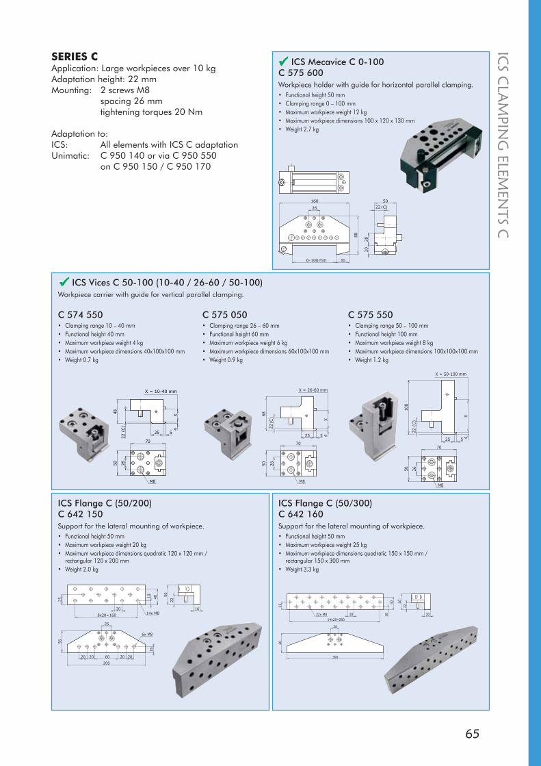
65
X4
(C)
22
25 5
6850 26
70
X = 26-60 mm
M8
2650
70
(C)
22
425 5
108
X
X = 50-100 mm
M8
2650
70
X4
525 (C)
22
48
X = 10-40 mm
M8
0- mm100 30
26 (C)22
160 50
28
20
88
200
56
50
22
16
15
60 20 202020
26
8x20=160
20
25
10 40
14x M8
6x M8
20
22
50
14x20=280
20
26
300
6025
10
40
22x M8
C 575 050• Clamping range 26 – 60 mm • Functional height 60 mm • Maximum workpiece weight 6 kg • Maximum workpiece dimensions 60x100x100 mm • Weight 0.9 kg
ICS Vices C 50-100 (10-40 / 26-60 / 50-100)Workpiece carrier with guide for vertical parallel clamping.
SERIES CApplication: Large workpieces over 10 kgAdaptation height: 22 mmMounting: 2 screws M8
spacing 26 mmtightening torques 20 Nm
Adaptation to:ICS: All elements with ICS C adaptation Unimatic: C 950 140 or via C 950 550
on C 950 150 / C 950 170
C 574 550• Clamping range 10 – 40 mm • Functional height 40 mm • Maximum workpiece weight 4 kg • Maximum workpiece dimensions 40x100x100 mm • Weight 0.7 kg
ICS Mecavice C 0-100C 575 600Workpiece holder with guide for horizontal parallel clamping.• Functional height 50 mm • Clamping range 0 – 100 mm • Maximum workpiece weight 12 kg • Maximum workpiece dimensions 100 x 120 x 130 mm • Weight 2.7 kg
ICS Flange C (50/200)C 642 150Support for the lateral mounting of workpiece.• Functional height 50 mm • Maximum workpiece weight 20 kg • Maximum workpiece dimensions quadratic 120 x 120 mm /
rectangular 120 x 200 mm • Weight 2.0 kg
ICS Flange C (50/300)C 642 160Support for the lateral mounting of workpiece.• Functional height 50 mm • Maximum workpiece weight 25 kg • Maximum workpiece dimensions quadratic 150 x 150 mm /
rectangular 150 x 300 mm • Weight 3.3 kg
C 575 550• Clamping range 50 – 100 mm • Functional height 100 mm • Maximum workpiece weight 8 kg • Maximum workpiece dimensions 100x100x100 mm• Weight 1.2 kg
ICS
CLA
MPIN
G ELEM
ENTS C
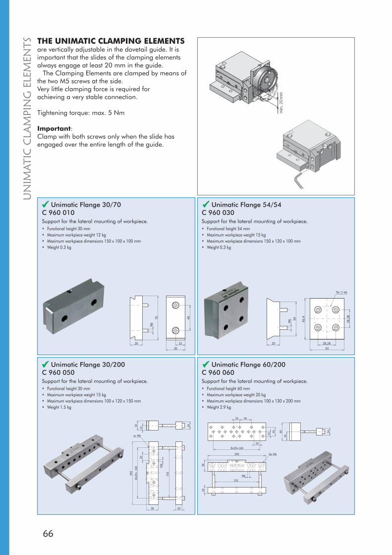
66
70
20
40
15
30
M6
20
5428
,28
28,28
M6 65
,454TK- 40
200
38
152
30 24
20
M8
8x20
=16
0
2015
for M6
200
38
152
60 24
20
M8
30
20 40
8x20=160
20
15
30
for M6
THE UNIMATIC CLAMPING ELEMENTSare vertically adjustable in the dovetail guide. It is important that the slides of the clamping elements always engage at least 20 mm in the guide.
The Clamping Elements are clamped by means of the two M5 screws at the side. Very little clamping force is required for achieving a very stable connection.
Tightening torque: max. 5 Nm
Important:Clamp with both screws only when the slide has engaged over the entire length of the guide.
Unimatic Flange 30/70C 960 010Support for the lateral mounting of workpiece.• Functional height 30 mm • Maximum workpiece weight 12 kg • Maximum workpiece dimensions 150 x 100 x 100 mm • Weight 0.3 kg
Unimatic Flange 54/54 C 960 030Support for the lateral mounting of workpiece.• Functional height 54 mm • Maximum workpiece weight 15 kg • Maximum workpiece dimensions 150 x 120 x 100 mm • Weight 0.3 kg
Unimatic Flange 30/200 C 960 050Support for the lateral mounting of workpiece.• Functional height 30 mm • Maximum workpiece weight 15 kg • Maximum workpiece dimensions 100 x 120 x 150 mm • Weight 1.5 kg
Unimatic Flange 60/200 C 960 060Support for the lateral mounting of workpiece.• Functional height 60 mm • Maximum workpiece weight 20 kg • Maximum workpiece dimensions 100 x 130 x 200 mm • Weight 2.9 kg
UN
IMAT
IC C
LAM
PIN
G E
LEM
ENTS
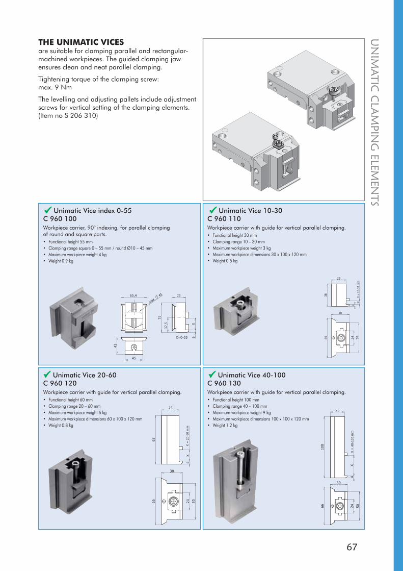
67
43
35
75
6X
45
37,5
65,4
max.
45
X=0-55
38
4
X
25
30
66 5024
X =
10-
30 m
m
25
68
4X
502466
30
X =
20-
60 m
m
108
4X
25
30
502466
X =
40-
100
mm
UN
IMATIC
CLA
MPIN
G ELEM
ENTS
Unimatic Vice index 0-55 C 960 100Workpiece carrier, 90° indexing, for parallel clamping of round and square parts.• Functional height 55 mm • Clamping range square 0 – 55 mm / round Ø10 – 45 mm • Maximum workpiece weight 4 kg • Weight 0.9 kg
Unimatic Vice 10-30 C 960 110Workpiece carrier with guide for vertical parallel clamping.• Functional height 30 mm • Clamping range 10 – 30 mm • Maximum workpiece weight 3 kg • Maximum workpiece dimensions 30 x 100 x 120 mm • Weight 0.5 kg
Unimatic Vice 20-60C 960 120Workpiece carrier with guide for vertical parallel clamping.• Functional height 60 mm • Clamping range 20 – 60 mm • Maximum workpiece weight 6 kg • Maximum workpiece dimensions 60 x 100 x 120 mm • Weight 0.8 kg
Unimatic Vice 40-100C 960 130Workpiece carrier with guide for vertical parallel clamping.• Functional height 100 mm • Clamping range 40 – 100 mm • Maximum workpiece weight 9 kg • Maximum workpiece dimensions 100 x 100 x 120 mm • Weight 1.2 kg
THE UNIMATIC VICESare suitable for clamping parallel and rectangular-machined workpieces. The guided clamping jaw ensures clean and neat parallel clamping.
Tightening torque of the clamping screw: max. 9 Nm
The levelling and adjusting pallets include adjustment screws for vertical setting of the clamping elements. (Item no S 206 310)
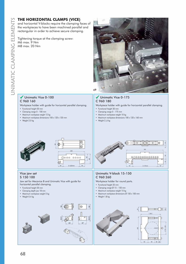
68
0-100mm
160
30
40
50
30
60
0-175mm45 40
260
5035
305
190
60 58 28
15 -
150
( )166
20
35 25
22,5
4743
30
22,5
30
Unimatic Vice 0-100 C 960 160Workpiece holder with guide for horizontal parallel clamping.• Functional height 50 mm • Clamping range 0 - 100 mm • Maximum workpiece weight 12 kg • Maximum workpiece dimensions 100 x 120 x 130 mm • Weight 2.0 kg
Unimatic Vice 0-175 C 960 180Workpiece holder with guide for horizontal parallel clamping.• Functional height 30 mm • Clamping range 0 - 175 mm • Maximum workpiece weight 10 kg • Maximum workpiece dimensions 100 x 120 x 160 mm • Weight 2.,6 kg
Unimatic V-block 15-150C 960 260Workpiece holder for round parts.• Functional height 35 mm • Clamping range Ø 15 – 150 mm • Maximum workpiece weight 15 kg • Maximum workpiece dimensions Ø 150 x 100 mm • Weight 1.8 kg
THE HORIZONTAL CLAMPS (VICE)and horizontal V-blocks require the clamping faces of the workpieces to have been machined parallel and rectangular in order to achieve secure clamping.
Tightening torque at the clamping screw: M6 max. 9 NmM8 max. 20 Nm
Vice jaw setS 150 100Jaw set for Mecavice B and Unimatic Vice with guide for horizontal parallel clamping.• Functional height 30 mm • Clamping depth jaw 18 mm • Maximum workpiece weight 5 kg • Weight 0.4 kg
UN
IMAT
IC C
LAM
PIN
G E
LEM
ENTS
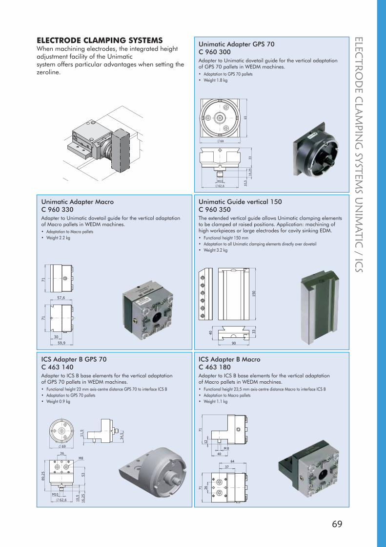
69
62,6
M10
3316
,25
10,5
65
69
57,6
59,9
30
7171
3340
90
150
62,6
M10
16,2
5
10,5
53
89,2
5
69
34,511
,5
26M8
71
12
40
71 26
M 8
64
37
ELECTRODE CLAMPING SYSTEMSWhen machining electrodes, the integrated height adjustment facility of the Unimatic system offers particular advantages when setting the zeroline.
Unimatic Adapter GPS 70 C 960 300Adapter to Unimatic dovetail guide for the vertical adaptation of GPS 70 pallets in WEDM machines.• Adaptation to GPS 70 pallets • Weight 1.8 kg
Unimatic Adapter MacroC 960 330Adapter to Unimatic dovetail guide for the vertical adaptation of Macro pallets in WEDM machines.• Adaptation to Macro pallets • Weight 2.2 kg
Unimatic Guide vertical 150C 960 350The extended vertical guide allows Unimatic clamping elements to be clamped at raised positions. Application: machining of high workpieces or large electrodes for cavity sinking EDM.• Functional height 150 mm • Adaptation to all Unimatic clamping elements directly over dovetail • Weight 3.2 kg
ICS Adapter B GPS 70C 463 140Adapter to ICS B base elements for the vertical adaptation of GPS 70 pallets in WEDM machines.• Functional height 23 mm axis-centre distance GPS 70 to interface ICS B• Adaptation to GPS 70 pallets • Weight 0.9 kg
ICS Adapter B MacroC 463 180Adapter to ICS B base elements for the vertical adaptation of Macro pallets in WEDM machines.• Functional height 23,5 mm axis-centre distance Macro to interface ICS B• Adaptation to Macro pallets • Weight 1.1 kg
ELECTR
OD
EC
LAM
PING
SYSTEMS
UN
IMATIC
/ ICS

70
2515
M6
40
60
100
40
46
24 8
57,5
11,5 M8
90 26
62,5
15,7
15
6084
36
5040
25
40
24
46
Unimatic Adapter SuperVice/Macro WEDMC 950 490Adapter for System 3R clamping elements with adaptation height 15 / 25 mm; with Unimatic dovetail slide.• Functional height Unimatic: 40 mm / SuperVice/Macro: 15 / 25 mmSuperVice/Macro: 15 / 25 mm: 15 / 25 mm • Adaptation to Unimatic system C 950 150 or C 950 170
SuperVice/Macro to all clamping elements with functional height 15 / 25 mm to all clamping elements with functional height 15 / 25 mm • Weight 1.3 kg
SYSTEM ADAPTERallows the user to employ the total diversity and strengths of all System 3R clamping elements on his machine and tooling configurations.
ICS Adapter B Unimatic C 642 300Adaptation of all Unimatic clamping elements on base elements with ICS B interface.• Adaptation height 12 mm • Adaptation to all Unimatic clamping elements • Weight 1.1 kg
Unimatic Adapter A, B or CAdapter for ICS clamping elements; with Unimatic dovetail slide.
C 950 510• ICS A• Weight 0.3 kg
C 950 530• ICS B• Weight 0.4 kg
C 950 550• ICS C• Weight 0.6 kg
AdaptersFor upgrading machines fitted with ICS. The adapter gives access to the entire 3Ruler/3P/3Ruler/3P/Macro range of WEDM accessories. range of WEDM accessories.
3R-200.1J-62• Length 140 mm• Weight 2.3 kg
3R-A6450• Length 85 mm• Weight 1.2 kg
3R-A6450-1• Length 140 mm• Weight 2 kg
Unimatic Adapter SuperVice/Macro WEDMC 950 480Adapter for System 3R clamping elements with adaptation height 15 / 25 mm; with Unimatic dovetail slide.• Functional height Unimatic: 40 mm / SuperVice/Macro: 15 / 25 mmSuperVice/Macro: 15 / 25 mm: 15 / 25 mm • Adaptation to Unimatic system C 950 150 or C 950 170
SuperVice/Macro to all clamping elements with functional height 15 / 25 mm to all clamping elements with functional height 15 / 25 mm • Weight 1.3 kg
SYST
EMA
DA
PTER
S
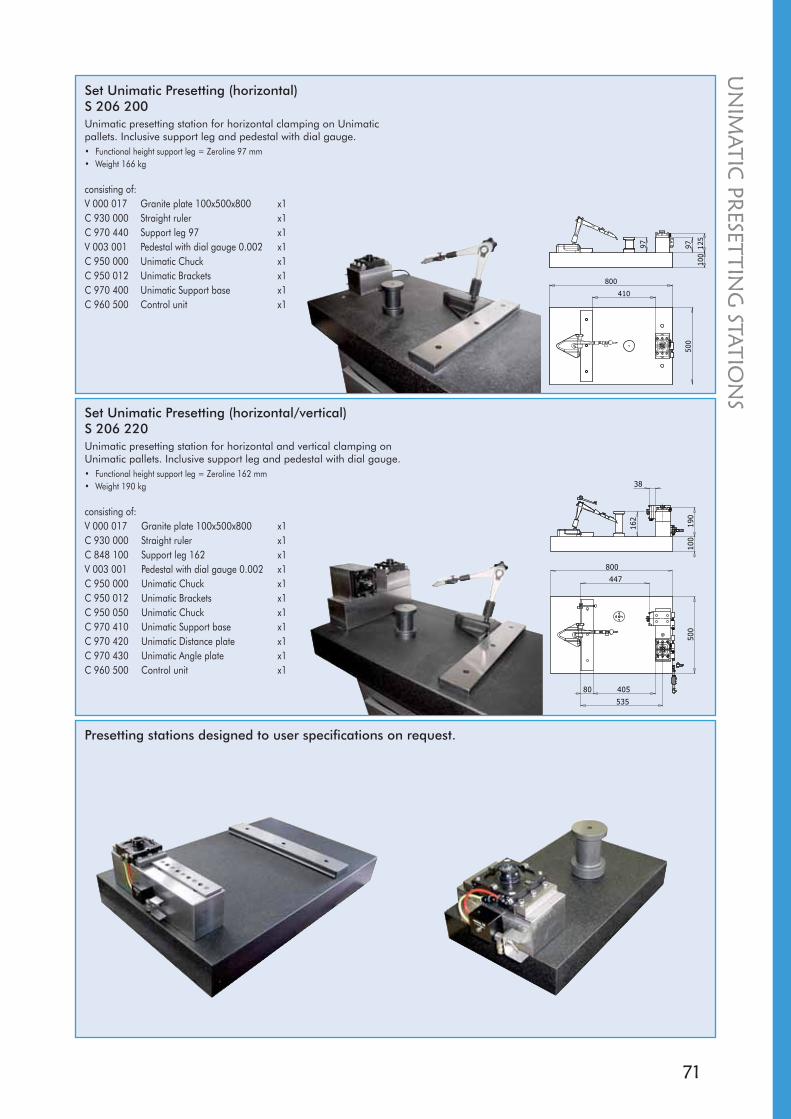
71
800
500
100
97 125
97
410
800
500
100
162
190
38
40580
535
447
Set Unimatic Presetting (horizontal)S 206 200Unimatic presetting station for horizontal clamping on Unimatic pallets. Inclusive support leg and pedestal with dial gauge.• Functional height support leg = Zeroline 97 mm• Weight 166 kg
consisting of:V 000 017 Granite plate 100x500x800 x1C 930 000 Straight ruler x1C 970 440 Support leg 97 x1V 003 001 Pedestal with dial gauge 0.002 x1C 950 000 Unimatic Chuck x1C 950 012 Unimatic Brackets x1C 970 400 Unimatic Support base x1C 960 500 Control unit x1
Set Unimatic Presetting (horizontal/vertical)S 206 220Unimatic presetting station for horizontal and vertical clamping on Unimatic pallets. Inclusive support leg and pedestal with dial gauge.• Functional height support leg = Zeroline 162 mm• Weight 190 kg
consisting of:V 000 017 Granite plate 100x500x800 x1C 930 000 Straight ruler x1C 848 100 Support leg 162 x1V 003 001 Pedestal with dial gauge 0.002 x1C 950 000 Unimatic Chuck x1C 950 012 Unimatic Brackets x1C 950 050 Unimatic Chuck x1C 970 410 Unimatic Support base x1C 970 420 Unimatic Distance plate x1C 970 430 Unimatic Angle plate x1C 960 500 Control unit x1
Presetting stations designed to user specifications on request.
UN
IMATIC
PRESET
TING
STATION
S
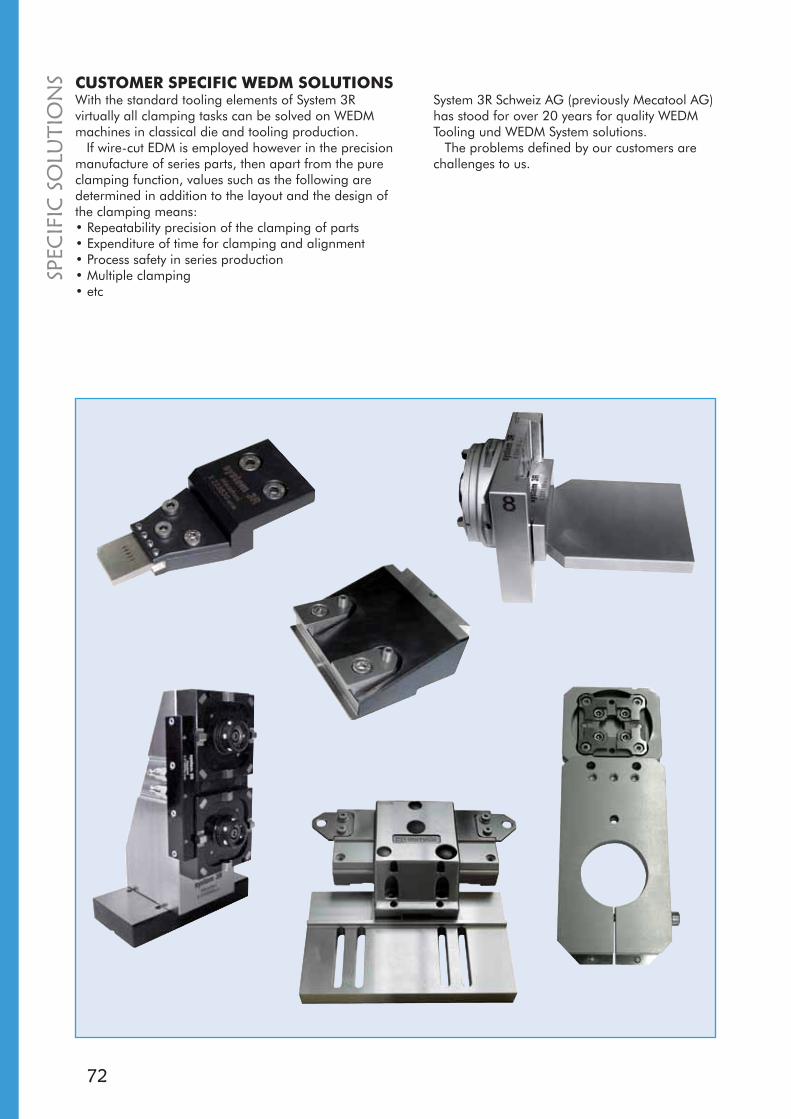
72
With the standard tooling elements of System 3R virtually all clamping tasks can be solved on WEDM machines in classical die and tooling production.
If wire-cut EDM is employed however in the precision manufacture of series parts, then apart from the pure clamping function, values such as the following are determined in addition to the layout and the design of the clamping means:• Repeatability precision of the clamping of parts • Expenditure of time for clamping and alignment • Process safety in series production • Multiple clamping • etc
CUSTOMER SPECIFIC WEDM SOLUTIONSSystem 3R Schweiz AG (previously Mecatool AG) has stood for over 20 years for quality WEDM Tooling und WEDM System solutions.
The problems defined by our customers are challenges to us.
SPEC
IFIC
SOLU
TIO
NS

73
CHANGE FRAMESare large palette systems which fit the dimensions of the WEDM machine table.
The sturdy construction enables even large workpieces to be clamped and to be changed with precise repeatability in the WEDM machine.
By adjustment of the clamping jaws to the current workpiece the expenditure on clamping and alignment can be significantly reduced.
System 3R change frames are available in versions for Unimatic or Macro WEDM machine table equipment.
FRA
ME SYSTEM
S

74
AC
CES
SOR
IES
Clamp kit M63R-230.1For clamping workpieces on rulers, etc.• Weight 1.8 kg
Cleaning agent3R-N009Highly effective cleaning agent for EDM machines and accessories.• Supplied in one-litre packs
Torque wrenches
3R-914-07• Torque 7 Nm
3R-914-10L• Torque 7.8 Nm
3R-914-10• Torque 10 Nm
3R-914-15• Torque 15 Nm
Bridge magnets
C 844 000• medium (8x12x55)
C 844 100• strong (8x18x55)
C 844 200• extra-strong (8x30x55)
C 844 300• medium (8x12x30)
Bridge magnets round
C 868 000• medium (Ø20)
C 868 100• strong Ø28)
Set ICS Double clamping M8C 860 000

75
UTILISE EVERY HOUR OF THE DAYAND NIGHT!An automatic production cell can generate revenue round the clock, seven days a week. Why be satisfied with 40 productive machine-hours a week when the same machine can achieve over 100 additional hours a week? Use every hour of the day and night for production!
WorkPal, WorkPartner and WorkMaster - three “aces” which boost your productivity and sharpen your competitiveness.
And not least – they bring faster payback on the investments you made.
WORKPAL COMPACT SERVO – MODEST DEMANDS, MAJORBENEFITSWorkPal Compact Servo is a simple step into the world of automation. It’s an easy-to-use, user-friendly pallet changer for automatic changing of pallets in wire EDM machines, for example.
A sliding door gives maximum access to the magazine, making it easier to manage the pallets. The extremely compact unit is simple to install. And what’s more, WorkPal Compact Servo only needs minimal floor space.
AU
TOM
ATION
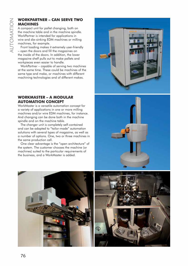
76
WORKMASTER – A MODULARAUTOMATION CONCEPTWorkMaster is a versatile automation concept for a variety of applications in one or more milling machines and/or wire EDM machines, for instance. And changing can be done both in the machine spindle and on the machine table.
The changer unit is completely self-contained and can be adapted to “tailor-made” automation solutions with several types of magazine, as well as a number of options. One, two or three machines in the same production cell.
One clear advantage is the “open architecture” of the system. The customer chooses the machine (or machines) suited to the particular requirements of the business, and a WorkMaster is added.
WORKPARTNER – CAN SERVE TWO MACHINESA compact unit for pallet changing, both on the machine table and in the machine spindle. WorkPartner is intended for applications in wire and die-sinking EDM machines or milling machines, for example.
Front loading makes it extremely user-friendly – open the doors and fill the magazines on the inside of the doors. In addition, the lower magazine shelf pulls out to make pallets and workpieces even easier to handle.
WorkPartner – capable of serving two machines at the same time. These could be machines of the same type and make, or machines with different machining technologies and of different makes.
AU
TOM
ATIO
N
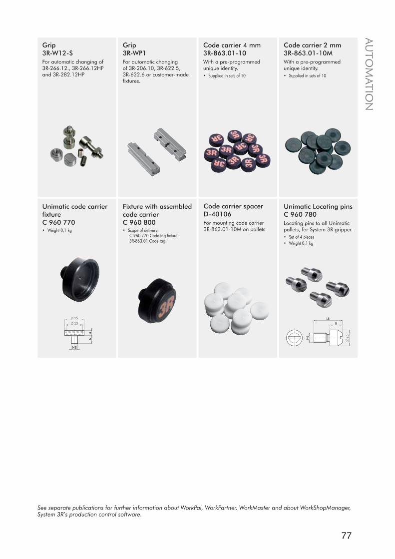
77
10
8
18
M6
15
4
M5
13
6
AU
TOM
ATION
Unimatic code carrierfixtureC 960 770• Weight 0,1 kg
Fixture with assembled code carrierC 960 800• Scope of delivery:
C 960 770 Code tag fixture3R-863.01 Code tag
Unimatic Locating pins C 960 780Locating pins to all Unimatic pallets, for System 3R gripper.• Set of 4 pieces• Weight 0,1 kg
Code carrier 4 mm3R-863.01-10With a pre-programmed unique identity.• Supplied in sets of 10
Code carrier 2 mm3R-863.01-10MWith a pre-programmed unique identity.• Supplied in sets of 10
Code carrier spacerD-40106For mounting code carrier 3R-863.01-10M on pallets
Grip3R-WP1For automatic changing of 3R-206.10, 3R-622.5, 3R-622.6 or customer-made fixtures.
Grip3R-W12-SFor automatic changing of 3R-266.12., 3R-266.12HP and 3R-282.12HP
See separate publications for further information about WorkPal, WorkPartner, WorkMaster and about WorkShopManager, System 3R’s production control software.
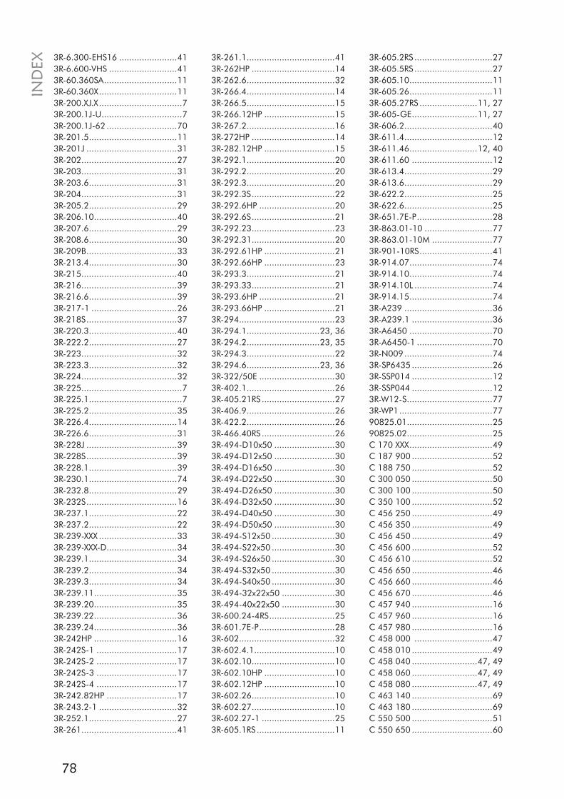
78
3R-6.300-EHS16 .......................413R-6.600-VHS ...........................413R-60.360SA.............................113R-60.360X...............................113R-200.XJ.X.................................73R-200.1J-U................................73R-200.1J-62 ............................703R-201.5...................................113R-201J ....................................313R-202......................................273R-203......................................313R-203.6...................................313R-204......................................313R-205.2...................................293R-206.10.................................403R-207.6...................................293R-208.6...................................303R-209B....................................333R-213.4...................................303R-215......................................403R-216......................................393R-216.6...................................393R-217-1 ..................................263R-218S....................................373R-220.3...................................403R-222.2...................................273R-223......................................323R-223.3...................................323R-224......................................323R-225........................................73R-225.1.....................................73R-225.2...................................353R-226.4...................................143R-226.6...................................313R-228J ....................................393R-228S....................................393R-228.1...................................393R-230.1...................................743R-232.8...................................293R-232S....................................163R-237.1...................................223R-237.2...................................223R-239-XXX ...............................333R-239-XXX-D............................343R-239.1...................................343R-239.2...................................343R-239.3...................................343R-239.11.................................353R-239.20.................................353R-239.22.................................363R-239.24.................................363R-242HP .................................163R-242S-1 ................................173R-242S-2 ................................173R-242S-3 ................................173R-242S-4 ................................173R-242.82HP ............................173R-243.2-1 ...............................323R-252.1...................................273R-261......................................41
3R-261.1...................................413R-262HP .................................143R-262.6...................................323R-266.4...................................143R-266.5...................................153R-266.12HP ............................153R-267.2...................................163R-272HP .................................143R-282.12HP ............................153R-292.1...................................203R-292.2...................................203R-292.3...................................203R-292.3S.................................223R-292.6HP ..............................203R-292.6S.................................213R-292.23.................................233R-292.31.................................203R-292.61HP ............................213R-292.66HP ............................233R-293.3...................................213R-293.33.................................213R-293.6HP ..............................213R-293.66HP ............................213R-294......................................233R-294.1.............................23, 363R-294.2.............................23, 353R-294.3...................................223R-294.6.............................23, 363R-322/50E ..............................303R-402.1...................................263R-405.21RS .............................273R-406.9...................................263R-422.2...................................263R-466.40RS .............................263R-494-D10x50 ........................303R-494-D12x50 ........................303R-494-D16x50 ........................303R-494-D22x50 ........................303R-494-D26x50 ........................303R-494-D32x50 ........................303R-494-D40x50 ........................303R-494-D50x50 ........................303R-494-S12x50 .........................303R-494-S22x50 .........................303R-494-S26x50 .........................303R-494-S32x50 .........................303R-494-S40x50 .........................303R-494-32x22x50 .....................303R-494-40x22x50 .....................303R-600.24-4RS..........................253R-601.7E-P..............................283R-602......................................323R-602.4.1................................103R-602.10.................................103R-602.10HP ............................103R-602.12HP ............................103R-602.26.................................103R-602.27.................................103R-602.27-1 .............................253R-605.1RS ...............................11
3R-605.2RS ...............................273R-605.5RS ...............................273R-605.10.................................113R-605.26.................................113R-605.27RS .......................11, 273R-605-GE..........................11, 273R-606.2...................................403R-611.4...................................123R-611.46...........................12, 403R-611.60 ................................123R-613.4...................................293R-613.6...................................293R-622.2...................................253R-622.6...................................253R-651.7E-P..............................283R-863.01-10 ...........................773R-863.01-10M ........................773R-901-10RS.............................413R-914.07.................................743R-914.10.................................743R-914.10L ...............................743R-914.15.................................743R-A239 ...................................363R-A239.1 ................................363R-A6450 .................................703R-A6450-1 ..............................703R-N009...................................743R-SP6435 ................................263R-SSP014 ................................123R-SSP044 ................................123R-W12-S..................................773R-WP1.....................................7790825.01..................................2590825.02..................................25C 170 XXX.................................49C 187 900 ................................52C 188 750 ................................52C 300 050 ................................50C 300 100 ................................50C 350 100 ................................52C 456 250 ................................49C 456 350 ................................49C 456 450 ................................49C 456 600 ................................52C 456 610 ................................52C 456 650 ................................46C 456 660 ................................46C 456 670 ................................46C 457 940 ................................16C 457 960 ................................16C 457 980 ................................16C 458 000 ...............................47C 458 010 ................................49C 458 040 ..........................47, 49C 458 060 ..........................47, 49C 458 080 ..........................47, 49C 463 140 ................................69C 463 180 ................................69C 550 500 ................................51C 550 650 ................................60
IND
EX

79
C 950 100 ................................56C 950 120 ................................56C 950 130 ................................56C 950 140 ................................56C 950 150 ................................55C 950 170 ................................55C 950 180 ................................56C 950 190 ...............................56C 950 280 ................................16C 950 290 ..........................47, 49 C 950 470 ................................15C 950 480 ................................70C 950 490 ................................70C 950 510 ................................70C 950 530 ................................70C 950 550 ................................70C 951 100 ................................56C 951 120 ................................56C 951 130 ................................56C 951 140 ................................56C 951 150 ................................55C 951 170 ................................55C 951 180 ................................56C 951 190 ................................56C 960 010 ................................66C 960 030 ................................66C 960 050 ................................66C 960 060 ................................66C 960 100 ................................67C 960 110 ................................67C 960 120 ................................67C 960 130 ................................67C 960 160 ................................68C 960 180 ................................68C 960 260 ................................68C 960 300 ................................69C 960 330 ................................69C 960 350 ................................69C 960 430 ................................58C 960 440 ................................47C 960 450 ................................58C 960 500 ................................58C 960 710 ................................58C 960 770 ................................77C 960 780 ................................77C 960 800 ................................77D-40106...................................77K-30266 ...................................12N 150 050................................50N 460 000................................50N 460 100................................50N 460 300................................50N 460 700................................50S 112 050.................................55S 112 060.................................55S 149 500.................................57S 149 900.................................46S 150 000.................................46S 150 100...........................63, 68S 150 310.................................46
S 150 500.................................43S 150 550.................................43S 150 560.................................43S 190 520.................................58S 190 900.................................58S 206 200.................................71S 206 220.................................71S 206 301.................................55S 206 4XX .................................45X 227 820.................................39
C 550 670 ................................61C 550 900 ................................51C 551 300 ................................51C 551 700 ................................51C 552 100 ................................51C 552 300 ................................62C 552 400 ................................62C 552 500 ................................62C 552 600 ................................46C 552 610 ................................46C 552 620 ................................46C 552 630 ................................44C 552 640 ................................44C 557 XXX.................................45C 558 XXX.................................45C 573 550 ................................63C 574 150 ................................63C 574 550 ................................65C 575 050 ................................65C 575 550 ................................65C 575 600 ................................65C 577 200 ................................61C 577 250 ................................60C 577 350 ................................63C 577 370 ................................63C 596 050 ................................64C 596 650 ................................64C 597 250 ................................64C 597 550 ................................64C 597 560 ................................46C 599 450 ................................60C 619 660 ................................61C 619 670 ..........................22, 61C 619 680 ................................22C 641 900 ................................61C 642 050 ................................64C 642 150 ................................65C 642 160 ................................65C 642 300 ................................70C 665 600 ................................44C 665 700 ................................44C 665 720 ................................44C 665 900 ................................44C 666 020 ................................43C 666 040 ................................43C 844 000 ................................74C 844 100 ................................74C 844 200 ................................74C 844 300 ................................74C 860 000 ................................74C 868 000 ................................74C 868 100 ................................74C 909 000 ................................52C 909 020 ................................52C 909 060 ................................52C 909 010 ................................52C 950 000 ................................54C 950 070 ................................54C 950 090 ................................47C 950 0XX ................................55
IND
EX


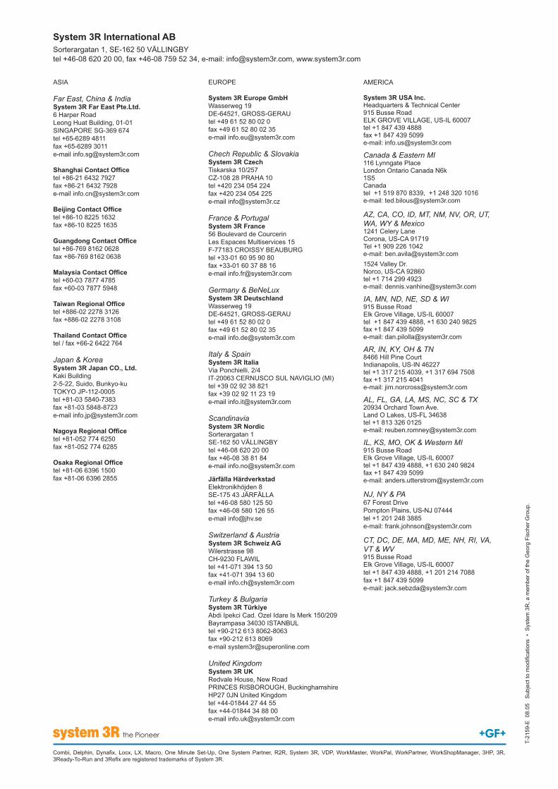
System 3R Europe GmbH
Chech Republic & SlovakiaSystem 3R Czech
France & PortugalSystem 3R France
Germany & BeNeLuxSystem 3R Deutschland
Italy & SpainSystem 3R Italia
ScandinaviaSystem 3R Nordic
Järfälla Härdverkstad
Switzerland & AustriaSystem 3R Schweiz AG
Turkey & BulgariaSystem 3R Türkiye
United KingdomSystem 3R UK
Far East, China & IndiaSystem 3R Far East Pte.Ltd.
Taiwan Re
Japan & KoreaSystem 3R Japan CO., Ltd.
System 3R USA Inc.
Canada & Eastern MI
1S5
AZ, CA, CO, ID, MT, NM, NV, OR, UT, WA, WY & Mexico
IA, MN, ND, NE, SD & WI
AR, IN, KY, OH & TN
AL, FL, GA, LA, MS, NC, SC & TX
IL, KS, MO, OK & Western MI
NJ, NY & PA
CT, DC, DE, MA, MD, ME, NH, RI, VA, VT & WV
System 3R International AB