Reference Manual For The Boston Scoliosis Brace€¦ · braces made in Germany in the last century...
66
1 Reference Manual For The Boston Scoliosis Brace
Transcript of Reference Manual For The Boston Scoliosis Brace€¦ · braces made in Germany in the last century...

1
Reference ManualFor The
Boston Scoliosis Brace
2
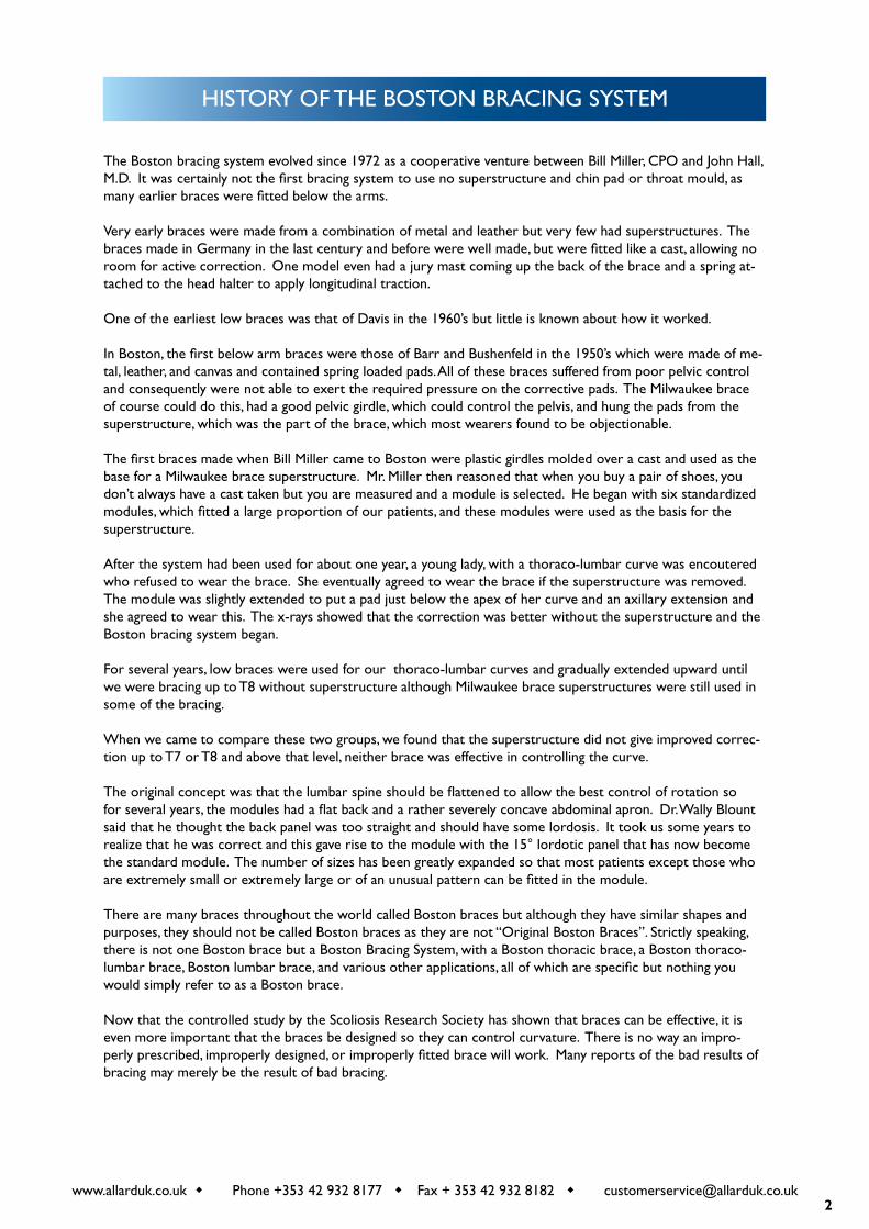
HISTORY OF THE BOSTON BRACING SYSTEM
www.allarduk.co.uk w Phone +353 42 932 8177 w Fax + 353 42 932 8182 w [email protected]
The Boston bracing system evolved since 1972 as a cooperative venture between Bill Miller, CPO and John Hall, M.D. It was certainly not the first bracing system to use no superstructure and chin pad or throat mould, as many earlier braces were fitted below the arms.
Very early braces were made from a combination of metal and leather but very few had superstructures. The braces made in Germany in the last century and before were well made, but were fitted like a cast, allowing no room for active correction. One model even had a jury mast coming up the back of the brace and a spring at-tached to the head halter to apply longitudinal traction.
One of the earliest low braces was that of Davis in the 1960’s but little is known about how it worked.
In Boston, the first below arm braces were those of Barr and Bushenfeld in the 1950’s which were made of me-tal, leather, and canvas and contained spring loaded pads. All of these braces suffered from poor pelvic control and consequently were not able to exert the required pressure on the corrective pads. The Milwaukee brace of course could do this, had a good pelvic girdle, which could control the pelvis, and hung the pads from the superstructure, which was the part of the brace, which most wearers found to be objectionable.
The first braces made when Bill Miller came to Boston were plastic girdles molded over a cast and used as the base for a Milwaukee brace superstructure. Mr. Miller then reasoned that when you buy a pair of shoes, you don’t always have a cast taken but you are measured and a module is selected. He began with six standardized modules, which fitted a large proportion of our patients, and these modules were used as the basis for the superstructure.
After the system had been used for about one year, a young lady, with a thoraco-lumbar curve was encoutered who refused to wear the brace. She eventually agreed to wear the brace if the superstructure was removed. The module was slightly extended to put a pad just below the apex of her curve and an axillary extension and she agreed to wear this. The x-rays showed that the correction was better without the superstructure and the Boston bracing system began.
For several years, low braces were used for our thoraco-lumbar curves and gradually extended upward until we were bracing up to T8 without superstructure although Milwaukee brace superstructures were still used in some of the bracing.
When we came to compare these two groups, we found that the superstructure did not give improved correc-tion up to T7 or T8 and above that level, neither brace was effective in controlling the curve.
The original concept was that the lumbar spine should be flattened to allow the best control of rotation so for several years, the modules had a flat back and a rather severely concave abdominal apron. Dr. Wally Blount said that he thought the back panel was too straight and should have some lordosis. It took us some years to realize that he was correct and this gave rise to the module with the 15° lordotic panel that has now become the standard module. The number of sizes has been greatly expanded so that most patients except those who are extremely small or extremely large or of an unusual pattern can be fitted in the module.
There are many braces throughout the world called Boston braces but although they have similar shapes and purposes, they should not be called Boston braces as they are not “Original Boston Braces”. Strictly speaking, there is not one Boston brace but a Boston Bracing System, with a Boston thoracic brace, a Boston thoraco-lumbar brace, Boston lumbar brace, and various other applications, all of which are specific but nothing you would simply refer to as a Boston brace.
Now that the controlled study by the Scoliosis Research Society has shown that braces can be effective, it is even more important that the braces be designed so they can control curvature. There is no way an impro-perly prescribed, improperly designed, or improperly fitted brace will work. Many reports of the bad results of bracing may merely be the result of bad bracing.

3
ABOUT ALLARD UK
Today, Allard UK continues to manufacture the Original Boston Brace. Previously a sister company of Boston Brace International Inc. and formerly known as Boston Brace Europe Ltd. The company is now under the ow-nership of the Camp Scandinavia A.B. (Sweden)
Allard Support UK continues the role of being the preferred supplier of spinal orthotic devices to the O&P field. As manufacturer of the Original Boston Brace for the conservative treatment of Scoliosis, we have develo-ped a wide knowledge base and technical expertise which allows us the ability to offer a single source of supply for all your spinal bracing needs.
4
PRINCIPLES OF THE BOSTON BRACES SYSTEM
OVERVIEWEach individual Boston Brace is constructed according to a basic set of principles outlined in this manual. By consistently using these principles, we believe that braces of the highest caliber will be constructed. The prin-ciples of fabrication of the Boston Brace are as follows:
Standardized Symmetrical ModuleBrace BlueprintLumbar and pelvic flexionActive and Passive curve correctionPad pressure at the apex and belowRelief opposite every area of force
STANDARDIZED SYMMETRICAL MODULEPrefabricated standardized symmetrical modules were original to the Boston Brace System at its inception. The advantages to the orthotist in terms of saving time, space and fabrication are obvious. Perhaps more important-ly, a symmetrical module will tend to correct the asymmetric spine toward normal.
BRACE BLUEPRINTA brace blueprint is drawn for each patient, by an orthotist or a trained technician. The blueprint allows the orthotist or technician to convert the standard symmetrical module to an individual orthosis. The patient`s x-rays are required to draw the blueprint. The brace blueprint focuses attention on the status of individual vertebra and we believe allows for a much more accurate design and placement of pads. Fabrication of Boston braces without the brace blueprint frequently results in pads that are inappropriately placed. At the conclusion of brace construction the brace can be compared to the original brace blueprint.
LUMBAR AND PELVIC FLEXIONThe Boston Brace scoliosis module is designed with a moderate degree of lumbar and pelvic flexion. This has been a basic Boston Brace principle since its inception and is a fundamental part of the design of the Boston Brace. By flexing the lumbar spine and pelvis a better grip can be obtained on the pelvis itself and a more stable foundation is made available for the rest of the brace. By placing the lumbar spine in flexion, the mid-section of the lumbar spine moves posteriorly where it is more accessible to lateral and derotating pressure. Studies have also shown that placing the lumbar spine in flexion per se causes an improvement in lateral curvature in the lumbar spine.
ACTIVE AS WELL AS PASSIVE CORRECTION.Passive correction is one of the fundamental principles of any brace. Several principles of design in the Boston Bracing system enhance active correction as well as passive correction. Wherever correction is sought, an area of “relief” is provided opposite the area of pressure so that the spine or body (in theory at least) can shift into the area of relief. In-brace exercises are also emphasized in the coordinated physical therapy program to enhance active correction. The patient is taught to pull away from the pads while in the brace both to provide more correction and skin relief. Whenever possible, the brace is kept to a minimum to allow normal motion of the trunk and spine outside the area of treatment.
5
PAD PRESSURE AT THE APEX AND BELOWExperience and mathematical modeling dictates that pad pressure should be at the apex of the curve and below for nearly all deformities. In the thoracic spine this is interpreted as the pressure in the mid-axillary line at the apical rib and below. Analysis of the brace blueprint will reveal that pad pressure above the apex is in theory transmitted to the vertebra that are already tipped toward the opposite side of the spine. Over the last decade virtually all bracing systems have also come to this conclusion and shifted the placement of pad pressure to the apex and below rather than centered on the apex.
RELIEF OPPOSITE EVERY AREA OF FORCEBoston brace principles dictate that opposite every force there should be an area of relief so that the trunk may shift. In most cases it is not necessary to actually heat relieve a void area since the Boston Brace modules are already symmetrical and they are being fitted to an asymmetrical torso.
SUMMARYThe Boston Bracing System has evolved over the years but few of these principles have been significantly alte-red. We believe that this list of principles can be applied to virtually every idiopathic scoliosis deformity. We encourage the orthotist or technician to continue to refer back to the principles of the Boston Brace when fabricating every Boston Brace. One should be able to look at a Boston Brace and check its correspondence with the blueprint, demonstrate the ways in which lumbar and pelvic flexion are achieved, active and passive correction achieved, and make sure that pad pressure is at the apices and below. There should be a demonstra-ble area of relief opposite most areas of pressure and force.
6
THE BOSTON BRACING SYSTEM FOR IDIOPATHIC SCOLIOSIS
TERMINOLOGYBoston Braces utilize a prefabricated, standardized symmetrical module chosen on the basis of the patient’s phy-sical dimensions. The individual patient orthosis is constructed using the radiograph-based blueprint designed by the orthotist. To help clarify terminology, the following explanations are offered.
MODULE TERMINOLOGYBoston Scoliosis ModuleOver the years, the standard module for scoliosis has been modified and redesigned for ease of fitting and bet-ter management of the spine and sagittal plane. Many sizes have been added. The standard module for all defor-mity applications is referred to as the Boston Scoliosis Module and was once designated the ‘15° module’.
CUSTOM MODULES:Different sizing characteristics can be ordered for individuals whose body proportions do not match the stan-dard modules.
BOSTON SCOLIOSIS BRACE TERMINOLOGYDifferent curves require different pad placements according to the severity and location. In order to minimize confusion we utilize the following terminology based on the highest component of the brace.
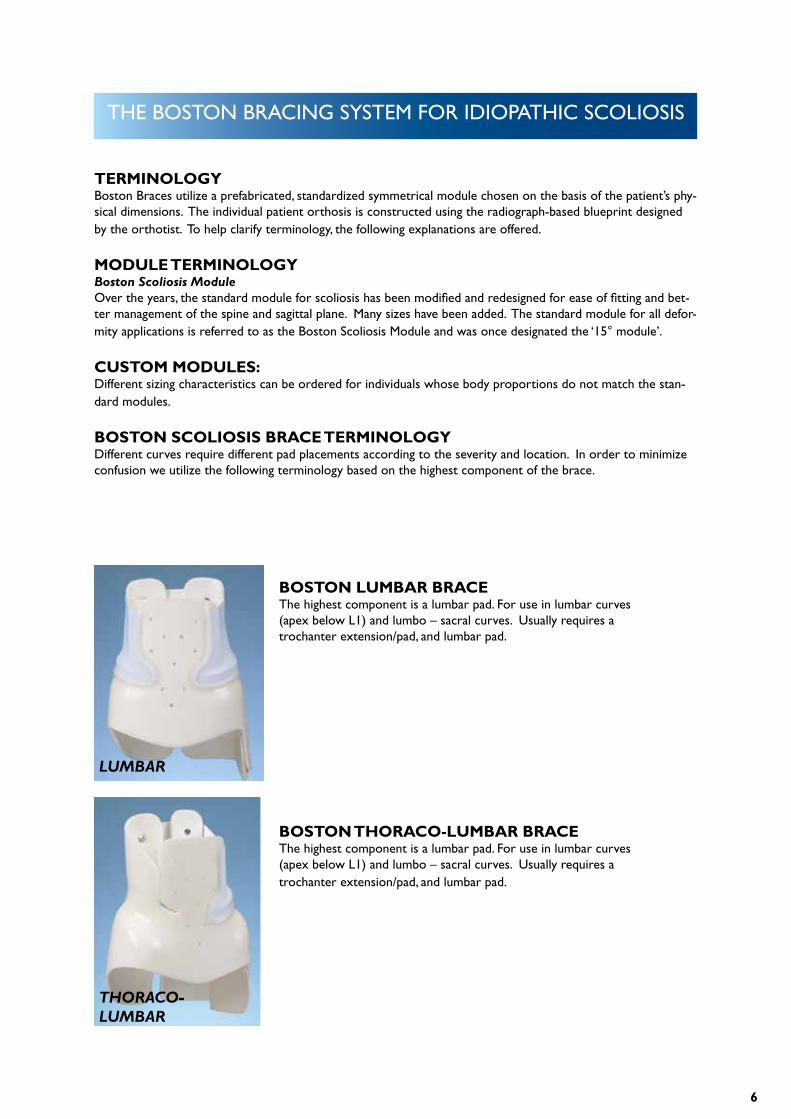
BOSTON LUMBAR BRACEThe highest component is a lumbar pad. For use in lumbar curves (apex below L1) and lumbo – sacral curves. Usually requires a trochanter extension/pad, and lumbar pad.
BOSTON THORACO-LUMBAR BRACEThe highest component is a lumbar pad. For use in lumbar curves (apex below L1) and lumbo – sacral curves. Usually requires a trochanter extension/pad, and lumbar pad.
LUMBAR
THORACO-LUMBAR
7
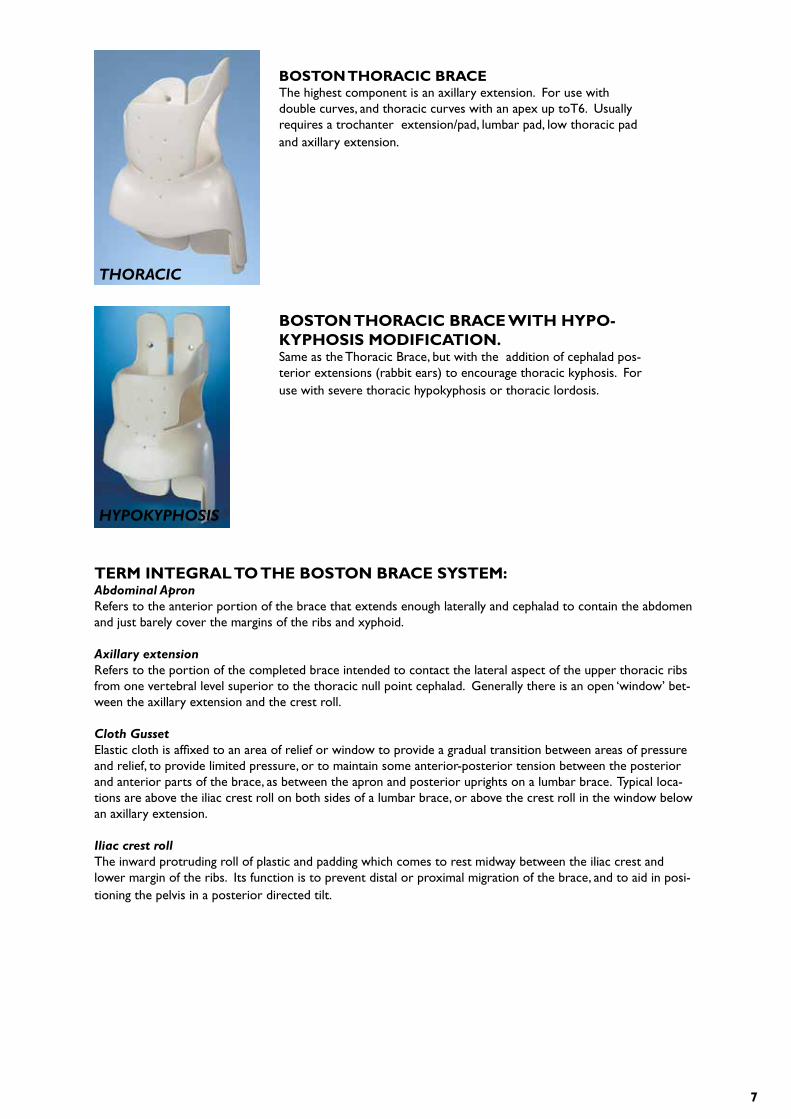
BOSTON THORACIC BRACEThe highest component is an axillary extension. For use with double curves, and thoracic curves with an apex up toT6. Usually requires a trochanter extension/pad, lumbar pad, low thoracic pad and axillary extension.
BOSTON THORACIC BRACE WITH HYPO-KYPHOSIS MODIFICATION.Same as the Thoracic Brace, but with the addition of cephalad pos-terior extensions (rabbit ears) to encourage thoracic kyphosis. For use with severe thoracic hypokyphosis or thoracic lordosis.
THORACIC
HYPOKYPHOSIS
TERM INTEGRAL TO THE BOSTON BRACE SYSTEM: Abdominal ApronRefers to the anterior portion of the brace that extends enough laterally and cephalad to contain the abdomen and just barely cover the margins of the ribs and xyphoid.
Axillary extensionRefers to the portion of the completed brace intended to contact the lateral aspect of the upper thoracic ribs from one vertebral level superior to the thoracic null point cephalad. Generally there is an open ‘window’ bet-ween the axillary extension and the crest roll.
Cloth GussetElastic cloth is affixed to an area of relief or window to provide a gradual transition between areas of pressure and relief, to provide limited pressure, or to maintain some anterior-posterior tension between the posterior and anterior parts of the brace, as between the apron and posterior uprights on a lumbar brace. Typical loca-tions are above the iliac crest roll on both sides of a lumbar brace, or above the crest roll in the window below an axillary extension.
Iliac crest rollThe inward protruding roll of plastic and padding which comes to rest midway between the iliac crest and lower margin of the ribs. Its function is to prevent distal or proximal migration of the brace, and to aid in posi-tioning the pelvis in a posterior directed tilt.
8
ModuleRefers to the prefabricated, symmetrical, Boston Scoliosis Module. There are a number of other thermoplastic prefabricated units available for rapid fabrication of Milwaukee braces and low profile, “underarm”, or TLSO bra-ces. These units differ in shape, materials and design from the Boston Brace Module System. (Most published results and this manual refer to Boston Braces utilizing Boston Brace prefabricated modules. If other prefabri-cated systems are utilized, they should not be called Boston Braces. Only in this way can we avoid confusion and continue to evaluate the relative merits of different systems.)
Posterior superior extensions (‘rabbit ears’) – “Hypokyphosis Modification”This term refers to the cephalad extension of the posterior plastic proximal to the inferior border of the sca-pula. The purpose of these extensions is to better control severe hypokyphosis by applying a forward directed force to the upper thoracic spine.
Thoracic extension, thoracic padRefers to the module plastic and pad extending cephalad from the iliac crest roll and intended to contact lower thoracic ribs.
Trochanter extension, trochanter padCommonly, plastic is left extending caudad to cover one greater trochanter. When needed, a pad is also used on the inner surface of the extension. The trochanter extension is essential to provide balance for the brace and avoid sideward tilting relative to the pelvis. Generally, the trochanter extension is placed on the side towards which L5 tilts.
9
BRACE DESIGN
PRINCIPLES OF BRACE DESIGNThe goal of “Brace Design” is to convert a prefabricated module useful for a number of patients, to an individual orthosis fabricated for the specific needs of one patient.
In the manufacturing of most objects, the availability of a “ Blueprint” facilitates the transition between an abst-ract design and a finished product. Likewise, in the fabrication of a Boston Brace it is helpful for the orthotist or technician to have a “blueprint”. Using the Cobb method the physician measures the patient’s x-ray and the degree value of curvature is documented on the x-ray. This x-ray will now become the blueprint for the fabrication of the brace.
CHOOSING THE CORRECT BRACEThe brace blueprint is the guide for choosing and constructing the proper brace to treat each type of scoliosis. The brace is named according to the highest curve being treated by the brace. Single curves with an apex supe-rior to T-6 or the upper curve of a triple spinal deformity may not be effectively treated by a spinal orthosis. THE BOSTON LUMBAR BRACEThe Lumbar Brace is used for curvatures with an apex below L1 or Lumborsacral curves. The module usually requires a lumbar pad on the convexity of the curve with a trochanter extension/ pad on the same side as the lumbar pad.
THE BOSTON THORACOLUMBAR BRACEThe thoraco-lumbar Brace is used for single curves with apex at T-10 to L-1 or double curves with a flexible upper thoracic curve, the upper half of which will not be braced. This module usually requires a lumbar pad and trochanter extension /pad on the convex side of the lower curve with a low thoracic extension /pad on the opposite side.
THE BOSTON THORACIC BRACEThe Thoracic Brace is used for curves with apex T-6 to T-10, or double curves. This module usually requires a thoracic extension /pad on the convex side of the thoracic curve, lumbar pad on the opposite side, and an axillary extension also on the opposite side to thoracic extension.
THE BOSTON PRO-KYPHOSIS THORACIC BRACEThe Pro-kyphosis Thoracic Brace is used in the patient with severe thoracic hypokyphosis (0 – 10 degrees) this module is similar to the Thoracic Brace with the additional cephalad extension to foster thoracic kyphosis. The apex of the thoracic lordosis should be below T-8.The Boston Bracing System may have a role in treatment of selected patients with paralytic scoliosis.The design of the brace requires that the patient have sensate skin and sufficient neuromuscular function to withdraw from the pressure points at the sites of pad placement. If the neuromuscular patient lacks either of these functions then it is recommended that the Boston Soft Spinal Orthosis or a total contact TLSO be used.
10
THE BRACE BLUEPRINT(SEE BLUEPRINT ON FOLLOWING PAGES.)
PRINCIPLES OF BRACE DESIGN
To create a Blueprint you must do the following:
1. Orient the x-ray and mark the spinous process of S1, draw a centre line from this point parallel to the side of the x-ray.
2. Find a “degree value” for each vertebra by drawing a line along the inferior edge of each verte bra across the centre line, and measuring the angle between this line and the centre line.
3. Measure a degree value for every vertebra.
4. Locate the “Null” point (apex) of the curve (the level at which the degree values change from right to left or vise versa). This point is used to determine the upper level of the pad placement.
5. Locate the L2-L3 disc space and draw a line perpendicular to the centre line. This is the level of the iliac crest rolls. (All vertical distances are marked from this line.)
6. Determine the tilt of L5. If L5 is tilted, draw in a trochanter extension covering the trochanter on the same side to which L5 tilts. If L5 is not tilted, a trochanter extension is not required, the exception to this rule is when the patient has a stiff thoracic curve that is unbalanced to one side, then consider a trochanter extension to the unbalanced side.
7. If a lumbar pad is required, draw the pad on the x-ray. Lumbar pad “full thickness” is measured from the level of the lumbar null point and for each vertebra with a degree value below. The position from x-ray to brace is marked relevant to the crest roll line. A tapered border of approximately ¾” is drawn beyond the full thickness border of the pad.
8. If a thoracic extension/pad is required, draw the extension/pad on the x-ray. The thoracic extension/pad is drawn as a medially directed force upwards at the rib corresponding to the null vertebra and downwards to the centre of the iliac crest roll.
9. If an axillary extension is required, draw the extension on the x-ray. The axillary extension is drawn as a medially directed force and an opposing force to the thoracic extension. The upper limit of the extension is determined by the highest vertebra tilting into the concavity of the thoracic curve. The lower limit is drawn at the rib corresponding to one vertebral level superior to the thoracic null point. (The upper limit generally cannot exceed the L5 level.)
11
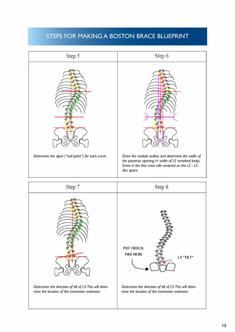
STEPS FOR MAKING A BOSTON BRACE BLUEPRINT
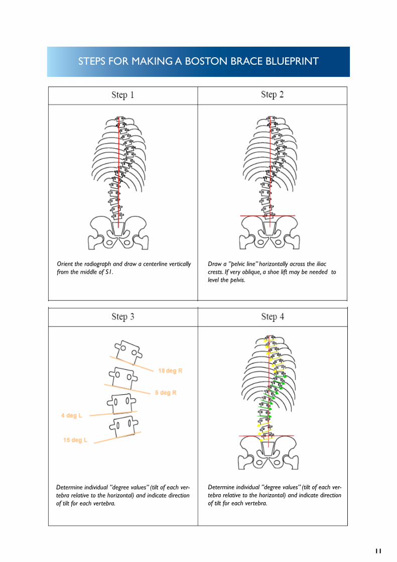
Orient the radiograph and draw a centerline vertically from the middle of S1.
Draw a ”pelvic line” horizontally across the iliac crests. If very oblique, a shoe lift may be needed to level the pelvis.
Determine individual ”degree values” (tilt of each ver-tebra relative to the horizontal) and indicate direction of tilt for each vertebra.
Determine individual ”degree values” (tilt of each ver-tebra relative to the horizontal) and indicate direction of tilt for each vertebra.
12
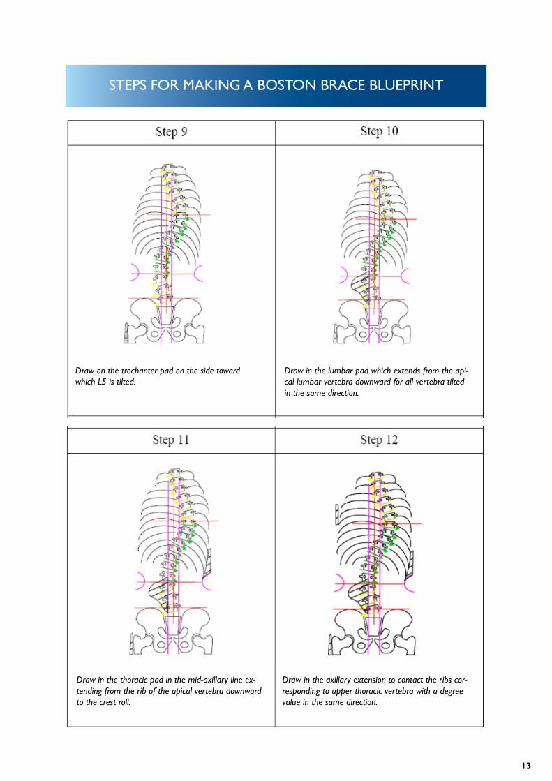
STEPS FOR MAKING A BOSTON BRACE BLUEPRINT
Determine the apex (”null point”) for each curve. Draw the module outline and determine the width of the posterior opening (= width of L5 vertebral body). Draw in the iliac crest rolls centered on the L2 - L3 disc space.
Determine the direction of tilt of L5. This will deter-mine the location of the trochanter extension.
Determine the direction of tilt of L5. This will deter-mine the location of the trochanter extension.
13
STEPS FOR MAKING A BOSTON BRACE BLUEPRINT
Draw on the trochanter pad on the side toward which L5 is tilted.
Draw in the lumbar pad which extends from the api-cal lumbar vertebra downward for all vertebra tilted in the same direction.
Draw in the thoracic pad in the mid-axillary line ex-tending from the rib of the apical vertebra downward to the crest roll.
Draw in the axillary extension to contact the ribs cor-responding to upper thoracic vertebra with a degree value in the same direction.
14
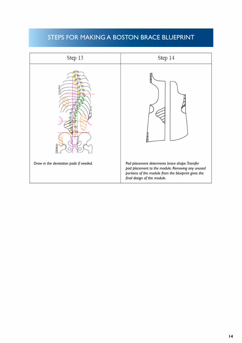
STEPS FOR MAKING A BOSTON BRACE BLUEPRINT
Draw in the derotation pads if needed. Pad placement determines brace shape. Transfer pad placement to the module. Removing any unused portions of the module from the blueprint gives the final design of the module.
15
STANDARD TRIM LINES
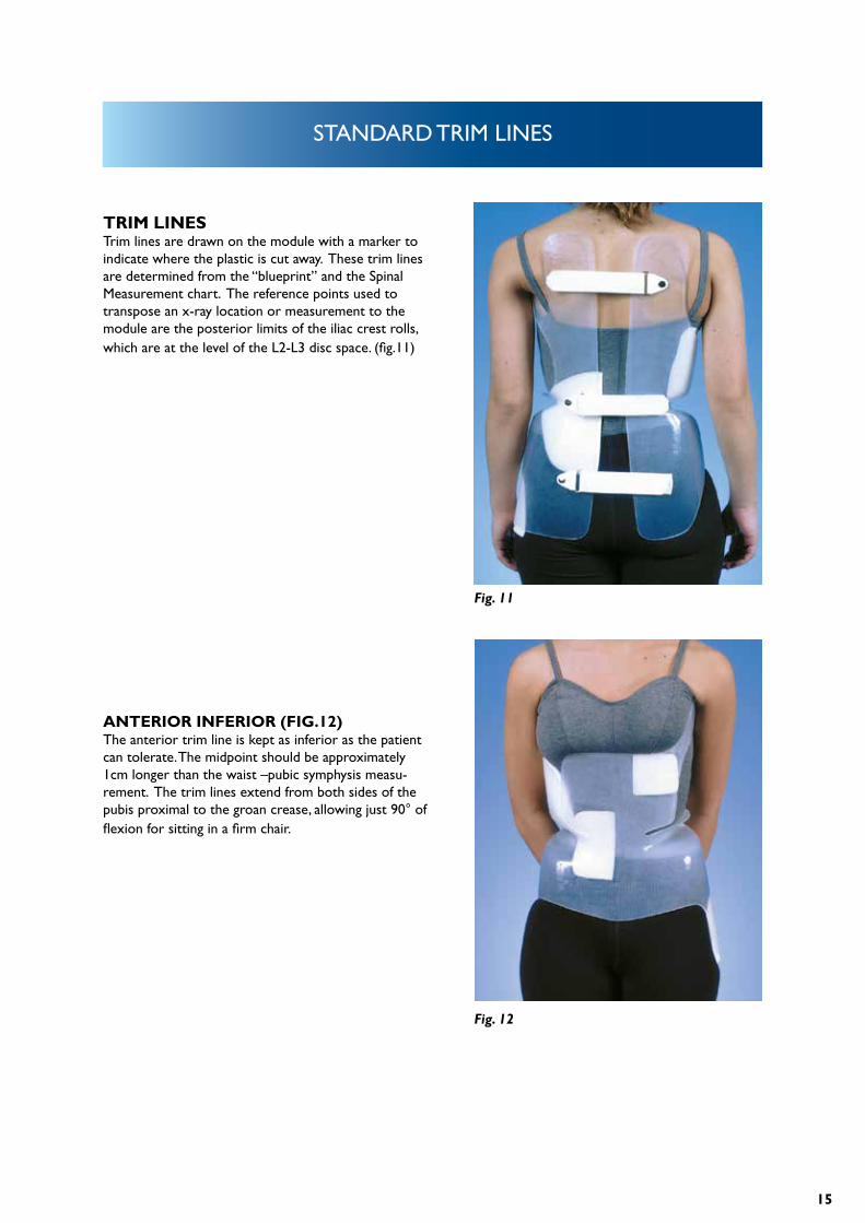
TRIM LINESTrim lines are drawn on the module with a marker to indicate where the plastic is cut away. These trim lines are determined from the “blueprint” and the Spinal Measurement chart. The reference points used to transpose an x-ray location or measurement to the module are the posterior limits of the iliac crest rolls, which are at the level of the L2-L3 disc space. (fig.11)
ANTERIOR INFERIOR (FIG.12)The anterior trim line is kept as inferior as the patient can tolerate. The midpoint should be approximately 1cm longer than the waist –pubic symphysis measu-rement. The trim lines extend from both sides of the pubis proximal to the groan crease, allowing just 90° of flexion for sitting in a firm chair.
Fig. 11
Fig. 12

16
STANDARD TRIM LINES
ANTERIOR SUPERIOR (FIG.13) The standard anterior superior trim line (top edge of the apron) is equal to the waist-xyphoid measurement. The base of the apron is at the level of the iliac crest and its width is approximately 50% of the width of the module at that level. The width of the apron is approx-imately 75% of the module width at the midpoint bet-ween the waist and xyphoid. The radius of the turns at the base of the apron should be at least 6mm to reduce the likelihood of a fracture developing at these points.
POSTERIOR INFERIOR (FIG. 14)The standard posterior trim line extends as low as possible, but not more than 1 –2 cm from the seat of a hard chair when the patient is sitting with hips flexed at 90°.
Fig. 13
Fig. 14
17
STANDARD TRIM LINES
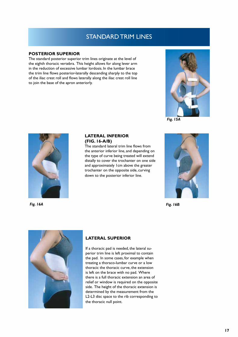
POSTERIOR SUPERIOR The standard posterior superior trim lines originate at the level of the eighth thoracic vertebra. This height allows for along lever arm in the reduction of excessive lumbar lordosis. In the lumbar brace the trim line flows posterior-laterally descending sharply to the top of the iliac crest roll and flows laterally along the iliac crest roll line to join the base of the apron anteriorly.
LATERAL INFERIOR (FIG. 16-A/B)The standard lateral trim line flows from the anterior inferior line, and depending on the type of curve being treated will extend distally to cover the trochanter on one side and approximately 1cm above the greater trochanter on the opposite side, curving down to the posterior inferior line.
LATERAL SUPERIOR
If a thoracic pad is needed, the lateral su-perior trim line is left proximal to contain the pad. In some cases, for example when treating a thoraco-lumbar curve or a low thoracic the thoracic curve, the extension is left on the brace with no pad. Where there is a full thoracic extension an area of relief or window is required on the opposite side. The height of the thoracic extension is determined by the measurement from the L2-L3 disc space to the rib corresponding to the thoracic null point.
Fig. 15A
Fig. 16A Fig. 16B
18
STANDARD TRIM LINES
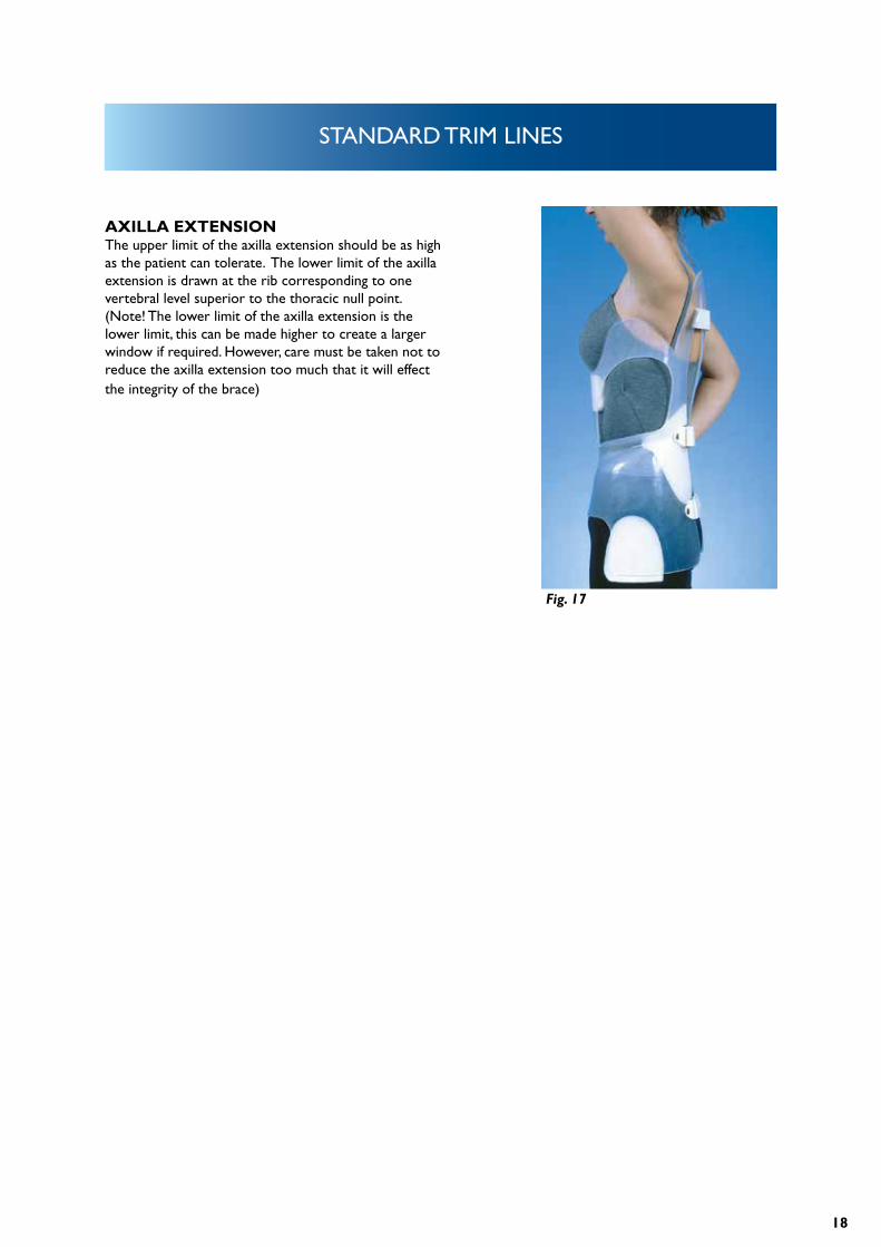
AXILLA EXTENSIONThe upper limit of the axilla extension should be as high as the patient can tolerate. The lower limit of the axilla extension is drawn at the rib corresponding to one vertebral level superior to the thoracic null point. (Note! The lower limit of the axilla extension is the lower limit, this can be made higher to create a larger window if required. However, care must be taken not to reduce the axilla extension too much that it will effect the integrity of the brace)
Fig. 17
19
BRACE CONSTRUCTION
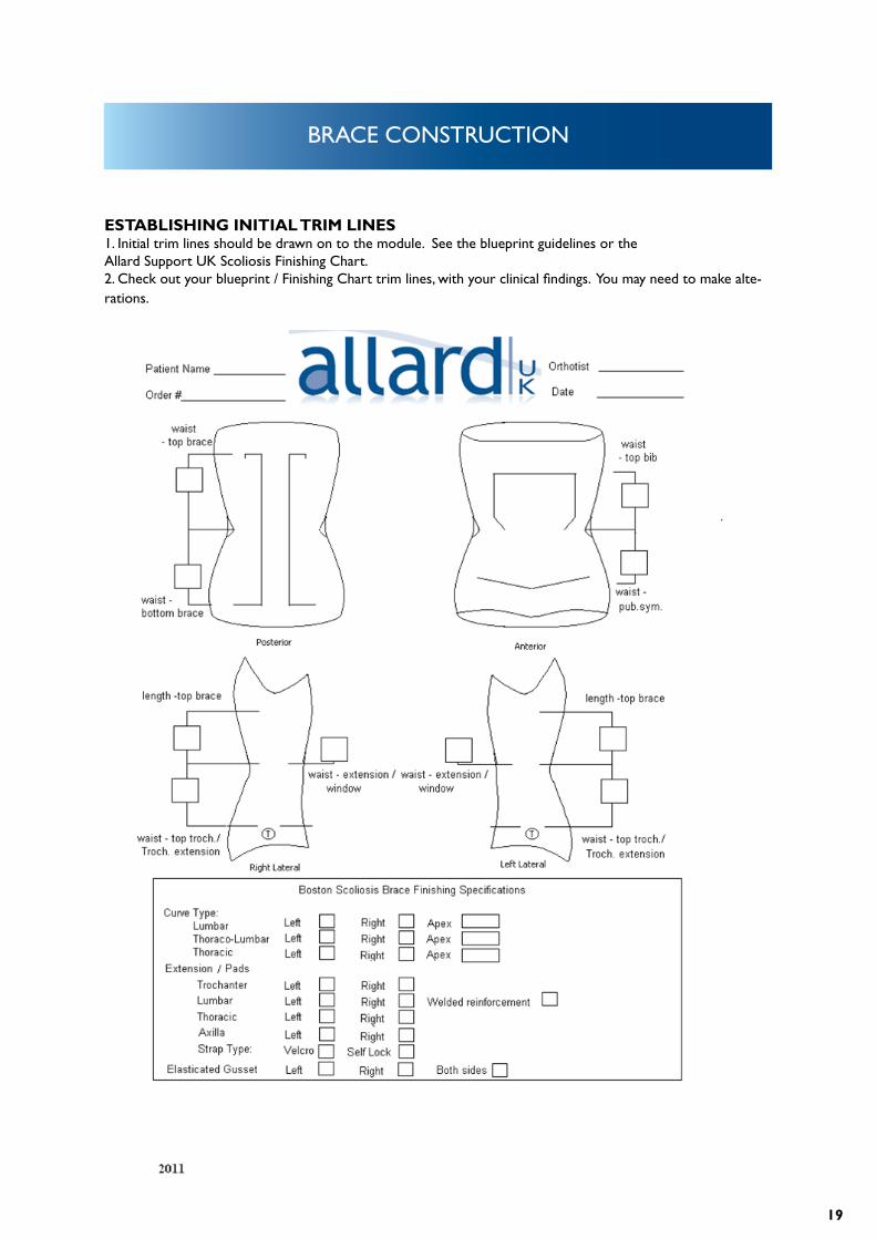
ESTABLISHING INITIAL TRIM LINES1. Initial trim lines should be drawn on to the module. See the blueprint guidelines or the Allard Support UK Scoliosis Finishing Chart.2. Check out your blueprint / Finishing Chart trim lines, with your clinical findings. You may need to make alte-rations.
20
BRACE CONSTRUCTION
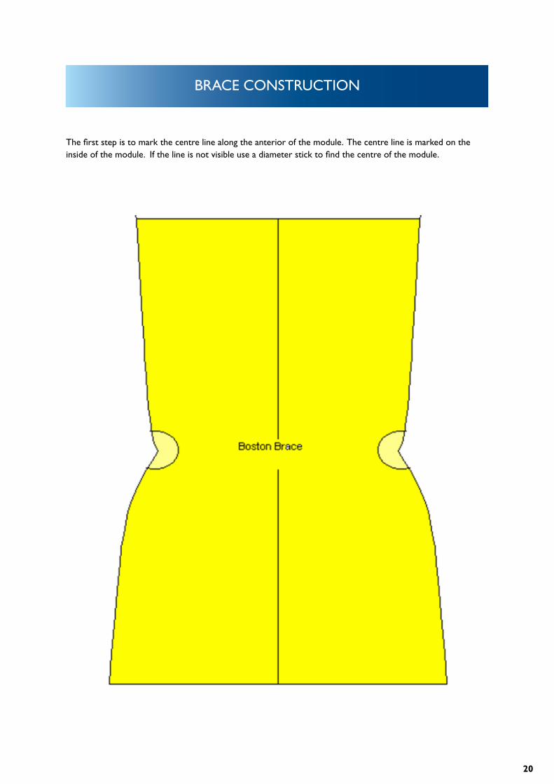
The first step is to mark the centre line along the anterior of the module. The centre line is marked on the inside of the module. If the line is not visible use a diameter stick to find the centre of the module.
21
BRACE CONSTRUCTION
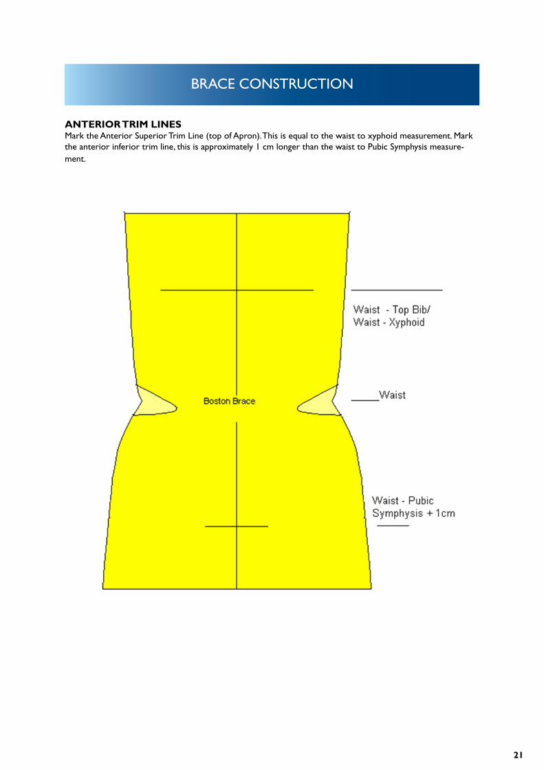
ANTERIOR TRIM LINESMark the Anterior Superior Trim Line (top of Apron). This is equal to the waist to xyphoid measurement. Mark the anterior inferior trim line, this is approximately 1 cm longer than the waist to Pubic Symphysis measure-ment.
22
BRACE CONSTRUCTION
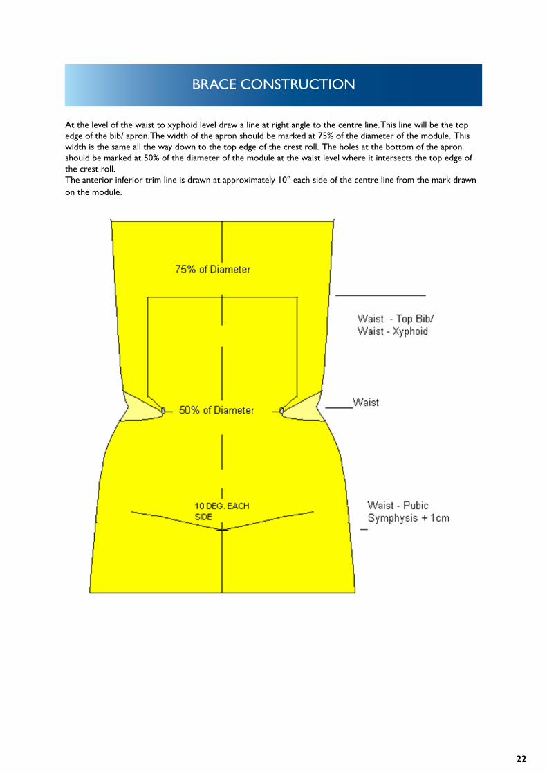
At the level of the waist to xyphoid level draw a line at right angle to the centre line. This line will be the top edge of the bib/ apron. The width of the apron should be marked at 75% of the diameter of the module. This width is the same all the way down to the top edge of the crest roll. The holes at the bottom of the apron should be marked at 50% of the diameter of the module at the waist level where it intersects the top edge of the crest roll. The anterior inferior trim line is drawn at approximately 10° each side of the centre line from the mark drawn on the module.
23
BRACE CONSTRUCTION
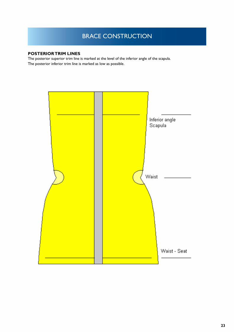
POSTERIOR TRIM LINESThe posterior superior trim line is marked at the level of the inferior angle of the scapula.The posterior inferior trim line is marked as low as possible.
24
BRACE CONSTRUCTION
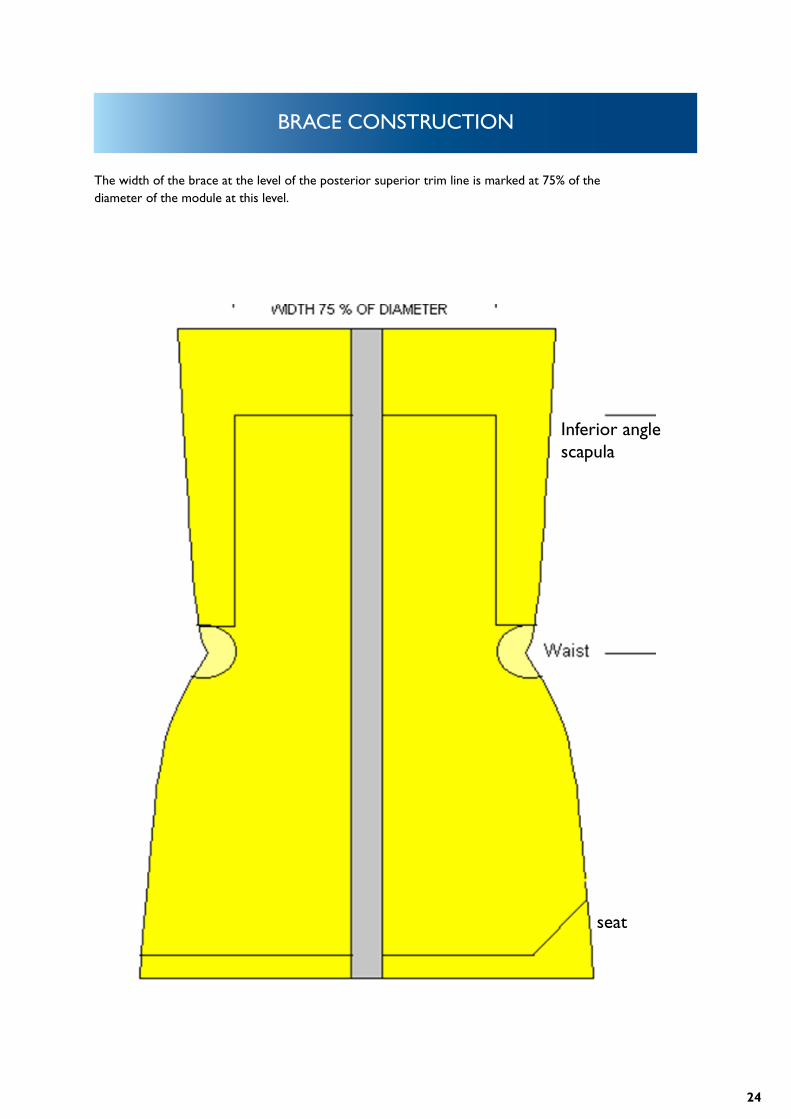
The width of the brace at the level of the posterior superior trim line is marked at 75% of the diameter of the module at this level.
Inferior anglescapula
seat
25
BRACE CONSTRUCTION
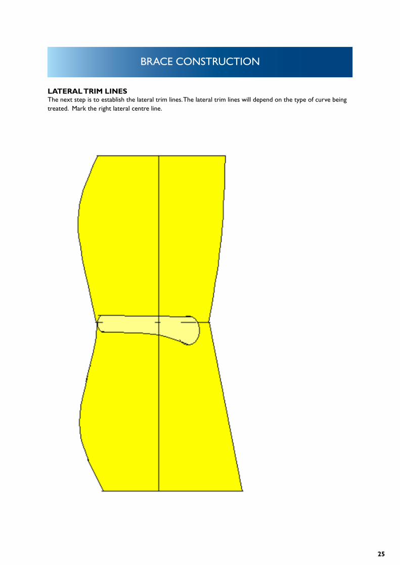
LATERAL TRIM LINESThe next step is to establish the lateral trim lines. The lateral trim lines will depend on the type of curve being treated. Mark the right lateral centre line.
26
BRACE CONSTRUCTION
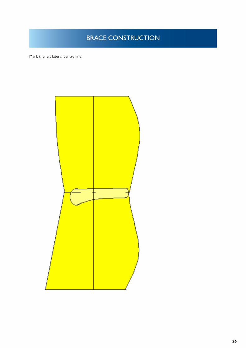
Mark the left lateral centre line.
27
BRACE CONSTRUCTION
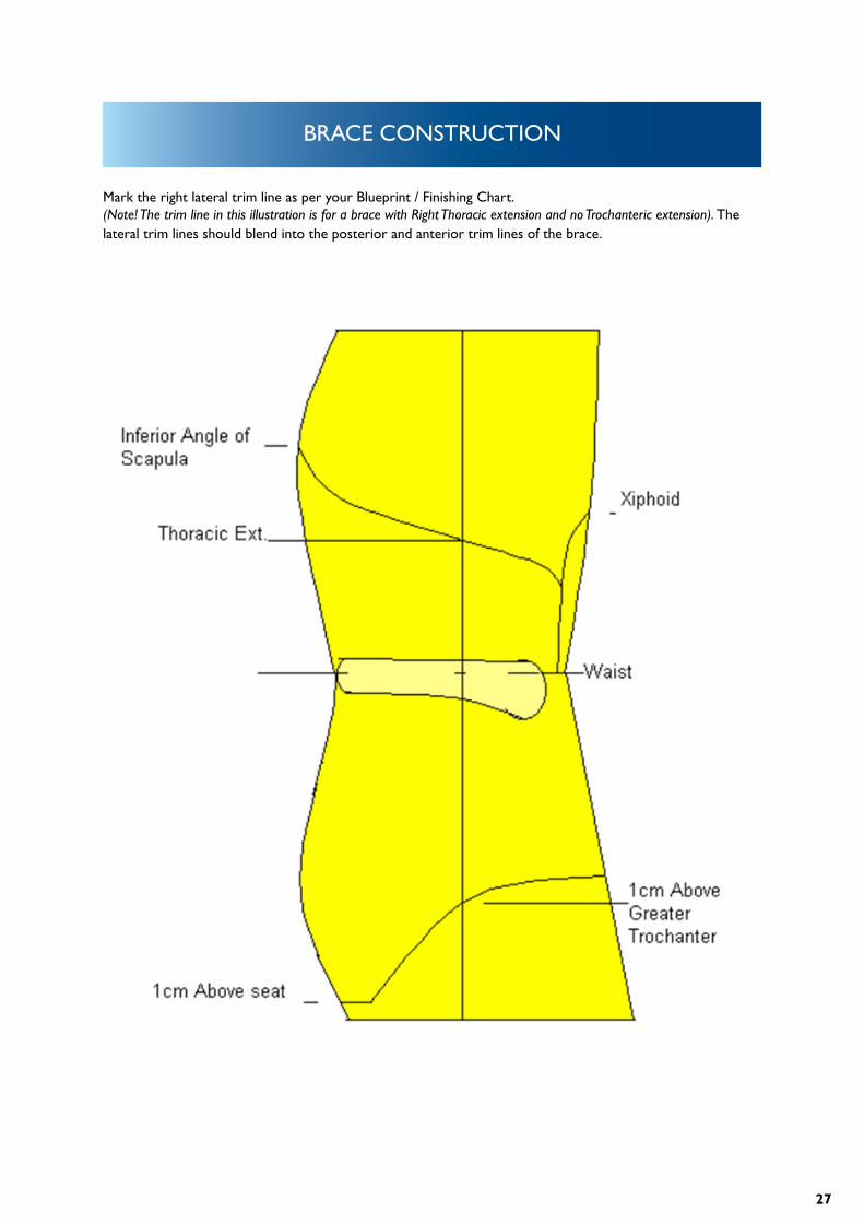
Mark the right lateral trim line as per your Blueprint / Finishing Chart.(Note! The trim line in this illustration is for a brace with Right Thoracic extension and no Trochanteric extension). The lateral trim lines should blend into the posterior and anterior trim lines of the brace.
28
BRACE CONSTRUCTION
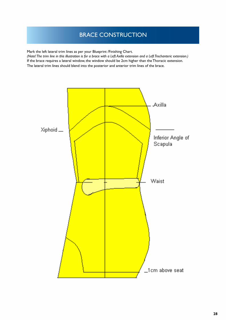
Mark the left lateral trim lines as per your Blueprint /Finishing Chart.(Note! The trim line in this illustration is for a brace with a Left Axilla extension and a Left Trochanteric extension.) If the brace requires a lateral window, the window should be 2cm higher than the Thoracic extension. The lateral trim lines should blend into the posterior and anterior trim lines of the brace.
29
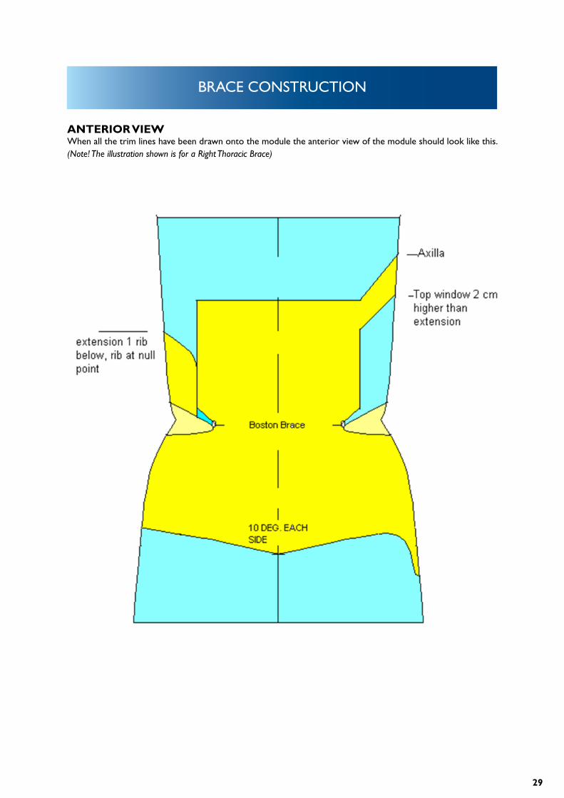
BRACE CONSTRUCTION
ANTERIOR VIEWWhen all the trim lines have been drawn onto the module the anterior view of the module should look like this. (Note! The illustration shown is for a Right Thoracic Brace)
30
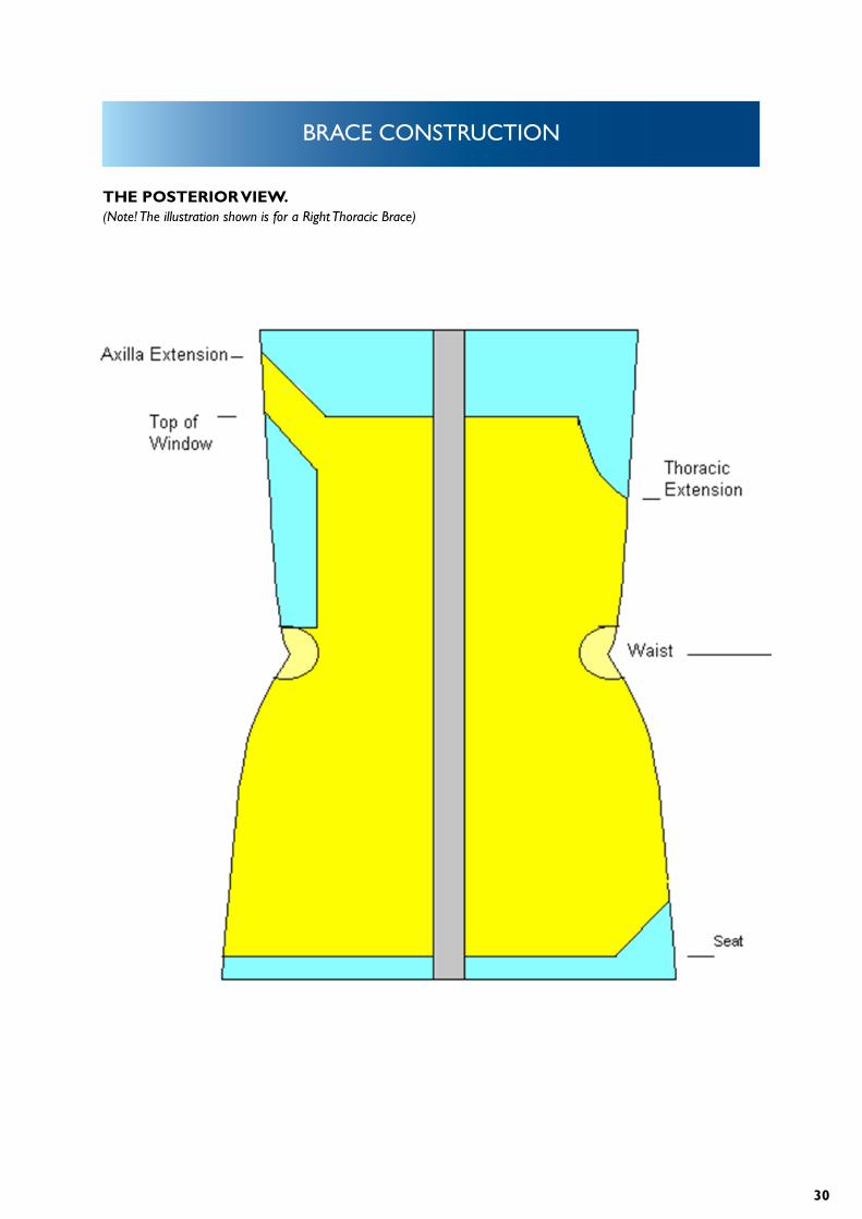
BRACE CONSTRUCTION
THE POSTERIOR VIEW.(Note! The illustration shown is for a Right Thoracic Brace)
31
BRACE CONSTRUCTION
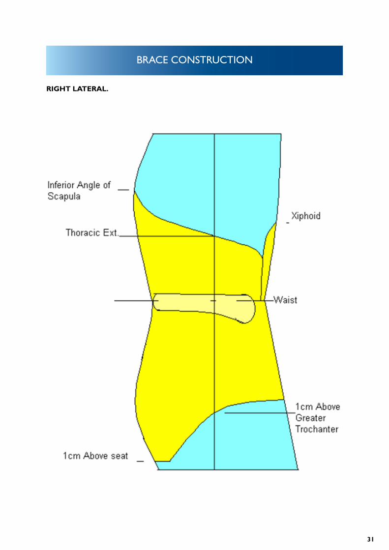
RIGHT LATERAL.
32
BRACE CONSTRUCTION
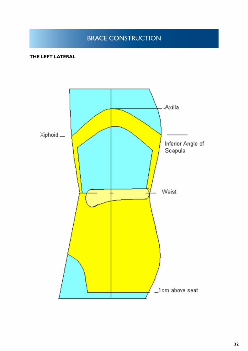
THE LEFT LATERAL
33
BRACE CONSTRUCTION
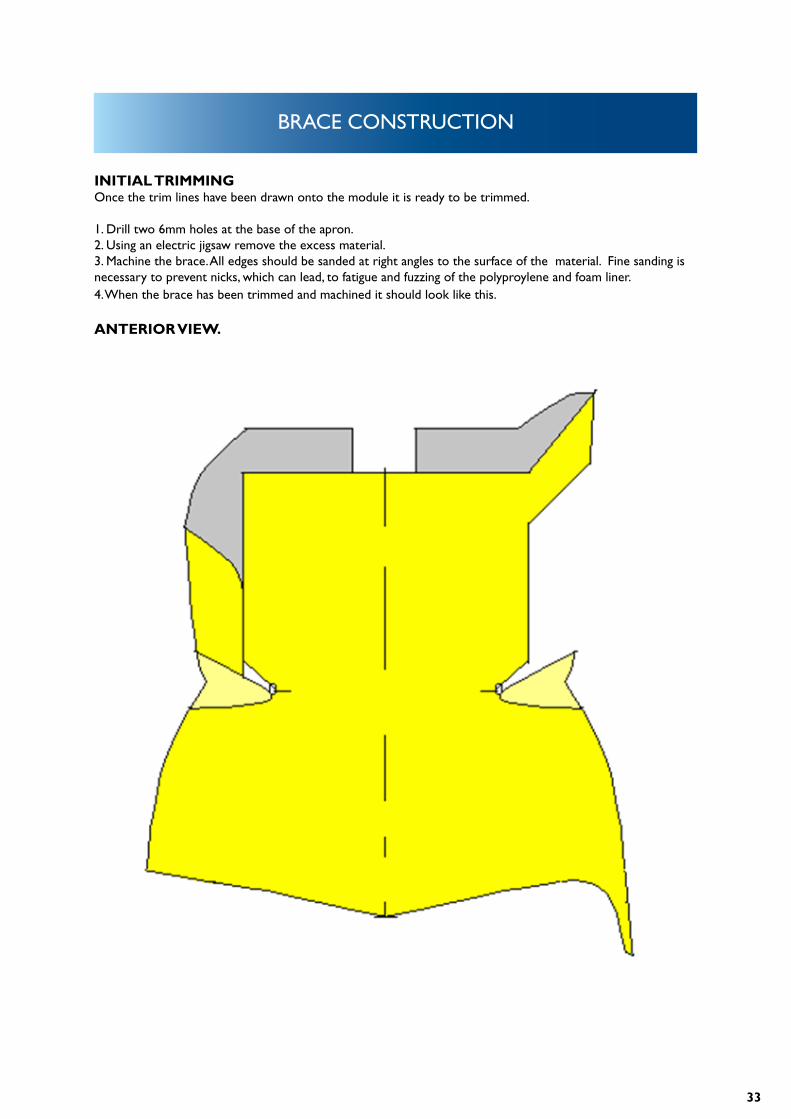
INITIAL TRIMMING Once the trim lines have been drawn onto the module it is ready to be trimmed.
1. Drill two 6mm holes at the base of the apron.2. Using an electric jigsaw remove the excess material.3. Machine the brace. All edges should be sanded at right angles to the surface of the material. Fine sanding is necessary to prevent nicks, which can lead, to fatigue and fuzzing of the polyproylene and foam liner.4. When the brace has been trimmed and machined it should look like this.
ANTERIOR VIEW.
34
BRACE CONSTRUCTION
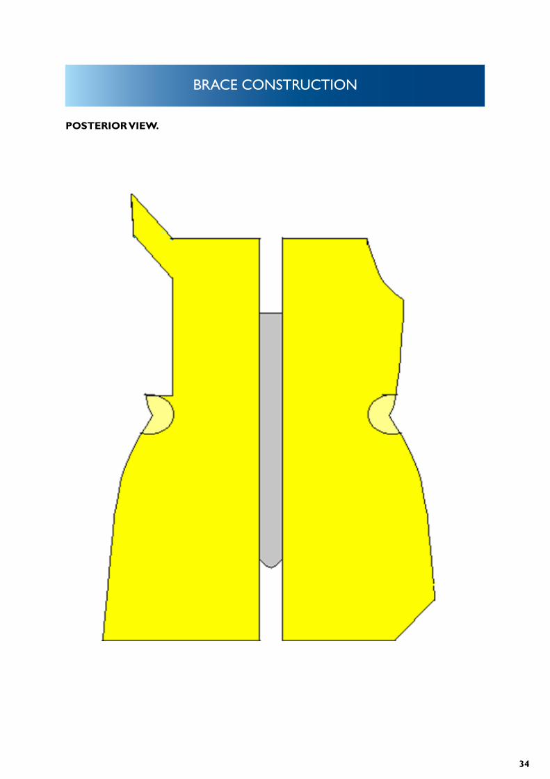
POSTERIOR VIEW.
35
BRACE CONSTRUCTION
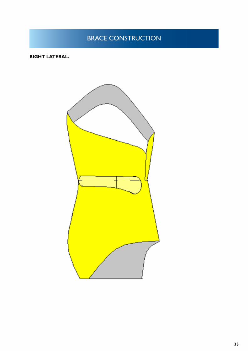
RIGHT LATERAL.
36
BRACE CONSTRUCTION
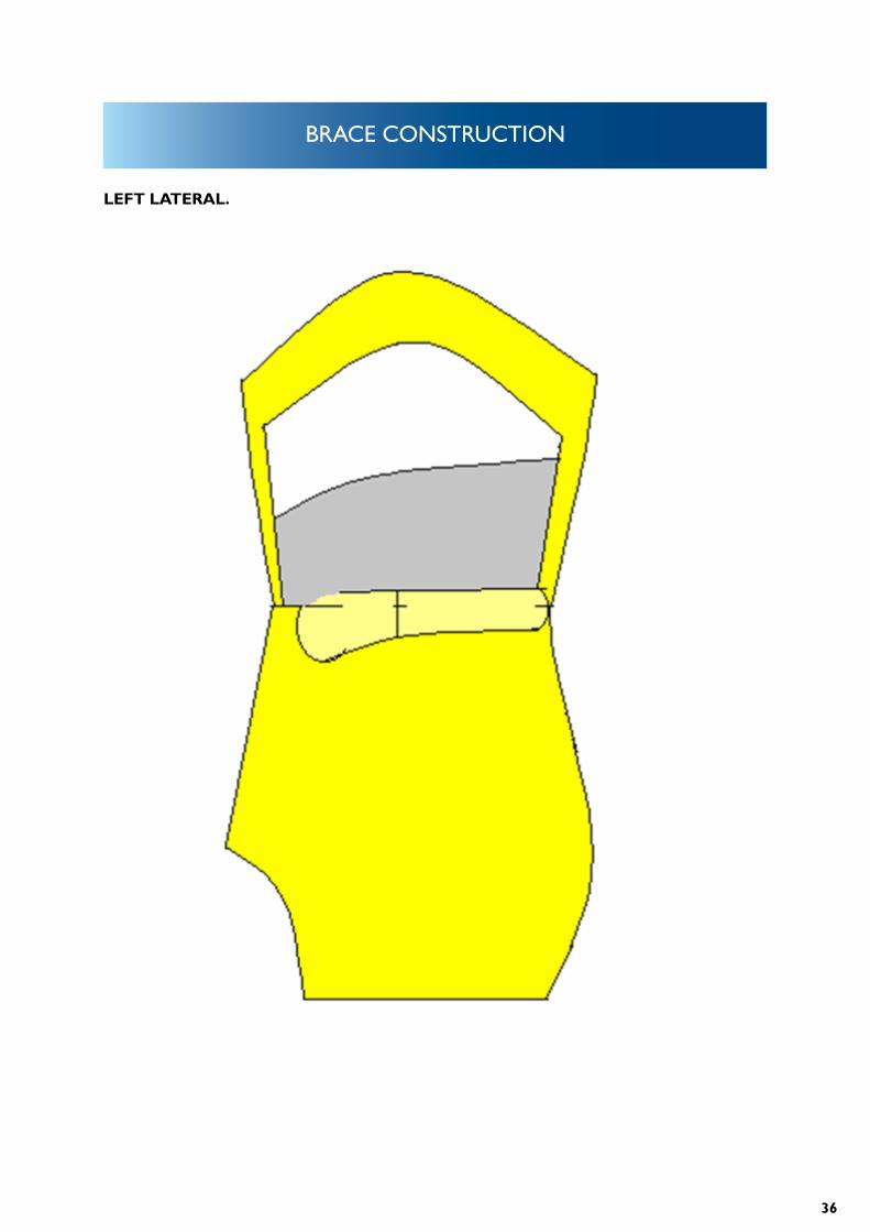
LEFT LATERAL.
37
BRACE CONSTRUCTION
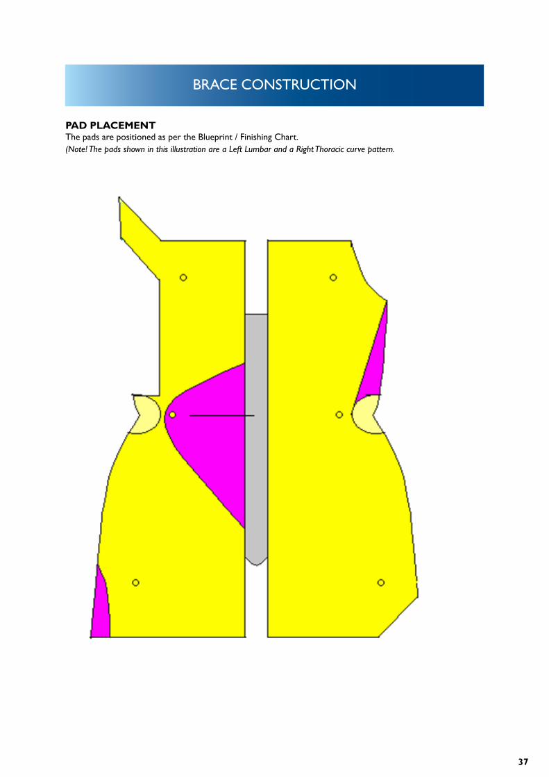
PAD PLACEMENTThe pads are positioned as per the Blueprint / Finishing Chart.(Note! The pads shown in this illustration are a Left Lumbar and a Right Thoracic curve pattern.
38
BRACE CONSTRUCTION
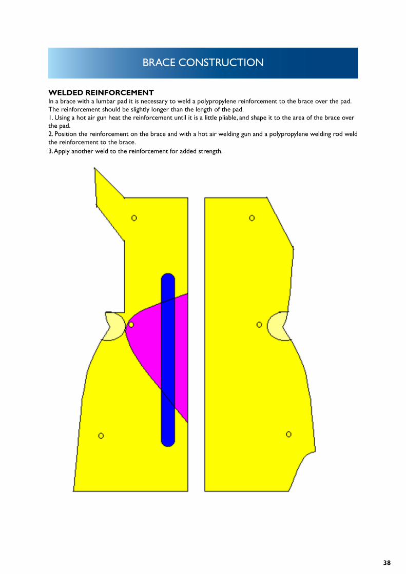
WELDED REINFORCEMENTIn a brace with a lumbar pad it is necessary to weld a polypropylene reinforcement to the brace over the pad. The reinforcement should be slightly longer than the length of the pad. 1. Using a hot air gun heat the reinforcement until it is a little pliable, and shape it to the area of the brace over the pad.2. Position the reinforcement on the brace and with a hot air welding gun and a polypropylene welding rod weld the reinforcement to the brace. 3. Apply another weld to the reinforcement for added strength.
39
BRACE CONSTRUCTION
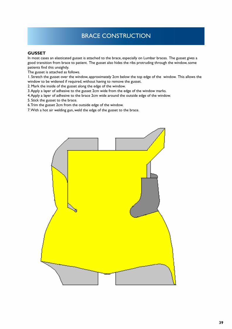
GUSSETIn most cases an elasticated gusset is attached to the brace, especially on Lumbar braces. The gusset gives a good transition from brace to patient. The gusset also hides the ribs protruding through the window, some patients find this unsightly.The gusset is attached as follows.1. Stretch the gusset over the window, approximately 2cm below the top edge of the window. This allows the window to be widened if required, without having to remove the gusset.2. Mark the inside of the gusset along the edge of the window.3. Apply a layer of adhesive to the gusset 2cm wide from the edge of the window marks.4. Apply a layer of adhesive to the brace 2cm wide around the outside edge of the window.5. Stick the gusset to the brace.6. Trim the gusset 2cm from the outside edge of the window.7. With a hot air welding gun, weld the edge of the gusset to the brace.
40
PAD PLACEMENT
PAD PLACEMENTThe goal of brace treatment is to prevent progression of the scoliosis by:1. Correcting the lateral curve.2. Correcting the malrotation3. Returning the torso to a balanced position over the sacrum4. Properly aligning the spine in the sagittal plane
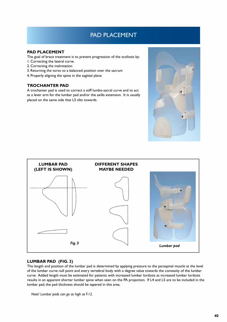
TROCHANTER PADA trochanter pad is used to correct a stiff lumbo-sacral curve and to act as a lever arm for the lumbar pad and/or the axilla extension. It is usually placed on the same side that L5 tilts towards.
LUMBAR PAD (FIG. 3)The length and position of the lumbar pad is determined by applying pressure to the paraspinal muscle at the level of the lumbar curve null point and every vertebral body with a degree value towards the convexity of the lumbar curve. Added length must be estimated for patients with increased lumbar lordosis as increased lumbar lordosis results in an apparent shorter lumbar spine when seen on the PA projection. If L4 and L5 are to be included in the lumbar pad, the pad thickness should be tapered in this area.
Note! Lumbar pads can go as high as T-12.
LUMBAR PAD (LEFT IS SHOWN)
DIFFERENT SHAPES MAYBE NEEDED
Fig. 3Lumbar pad
41
PAD PLACEMENT
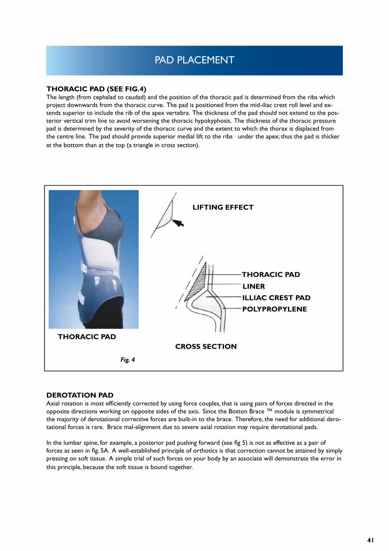
THORACIC PAD (SEE FIG.4)The length (from cephalad to caudad) and the position of the thoracic pad is determined from the ribs which project downwards from the thoracic curve. The pad is positioned from the mid-iliac crest roll level and ex-tends superior to include the rib of the apex vertebra. The thickness of the pad should not extend to the pos-terior vertical trim line to avoid worsening the thoracic hypokyphosis. The thickness of the thoracic pressure pad is determined by the severity of the thoracic curve and the extent to which the thorax is displaced from the centre line. The pad should provide superior medial lift to the ribs under the apex; thus the pad is thicker at the bottom than at the top (a triangle in cross section).
DEROTATION PADAxial rotation is most efficiently corrected by using force couples, that is using pairs of forces directed in the opposite directions working on opposite sides of the axis. Since the Boston Brace ™ module is symmetrical the majority of derotational corrective forces are built-in to the brace. Therefore, the need for additional dero-tational forces is rare. Brace mal-alignment due to severe axial rotation may require derotational pads.
In the lumbar spine, for example, a posterior pad pushing forward (see fig 5) is not as effective as a pair of forces as seen in fig. 5A. A well-established principle of orthotics is that correction cannot be attained by simply pressing on soft tissue. A simple trial of such forces on your body by an associate will demonstrate the error in this principle, because the soft tissue is bound together.
LIFTING EFFECT
THORACIC PAD
ILLIAC CREST PAD
LINER
POLYPROPYLENE
CROSS SECTIONTHORACIC PAD
Fig. 4
42
PAD PLACEMENT
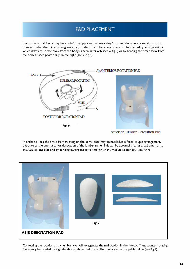
Just as the lateral forces require a relief area opposite the correcting force, rotational forces require an area of relief so that the spine can migrate axially to derotate. These relief areas can be created by an adjacent pad which draws the brace away from the body as seen anteriorly (see A fig.6) or by bending the brace away from the body as seen posteriorly on the right (see C,fig 6).
Correcting the rotation at the lumbar level will exaggerate the malrotation in the thorax. Thus, counter-rotating forces may be needed to align the thorax above and to stabilize the brace on the pelvis below (see fig.8).
In order to keep the brace from twisting on the pelvis, pads may be needed, in a force-couple arrangement, opposite to the ones used for derotation of the lumbar spine. This can be accomplished by a pad anterior to the ASIS on one side and by bending inward the lower margin of the module posteriorly (see fig 7)
Fig. 6
Fig. 7
ASIS DEROTATION PAD
43
PAD PLACEMENT
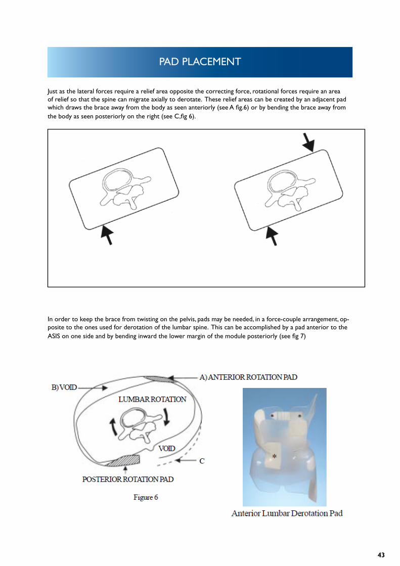
Just as the lateral forces require a relief area opposite the correcting force, rotational forces require an area of relief so that the spine can migrate axially to derotate. These relief areas can be created by an adjacent pad which draws the brace away from the body as seen anteriorly (see A fig.6) or by bending the brace away from the body as seen posteriorly on the right (see C,fig 6).
In order to keep the brace from twisting on the pelvis, pads may be needed, in a force-couple arrangement, op-posite to the ones used for derotation of the lumbar spine. This can be accomplished by a pad anterior to the ASIS on one side and by bending inward the lower margin of the module posteriorly (see fig 7)
Fig. 6
Fig. 5 Fig. 5A
44
PAD PLACEMENT
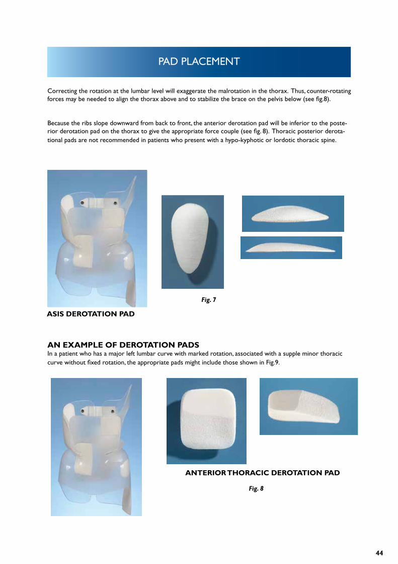
Correcting the rotation at the lumbar level will exaggerate the malrotation in the thorax. Thus, counter-rotating forces may be needed to align the thorax above and to stabilize the brace on the pelvis below (see fig.8).
Because the ribs slope downward from back to front, the anterior derotation pad will be inferior to the poste-rior derotation pad on the thorax to give the appropriate force couple (see fig. 8). Thoracic posterior derota-tional pads are not recommended in patients who present with a hypo-kyphotic or lordotic thoracic spine.
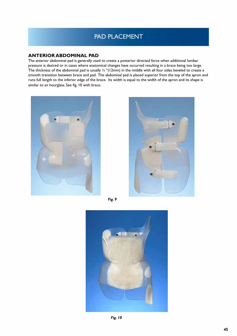
AN EXAMPLE OF DEROTATION PADSIn a patient who has a major left lumbar curve with marked rotation, associated with a supple minor thoracic curve without fixed rotation, the appropriate pads might include those shown in Fig.9.
Fig. 7
Fig. 8
ASIS DEROTATION PAD
ANTERIOR THORACIC DEROTATION PAD
45
PAD PLACEMENT
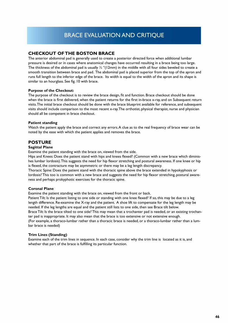
ANTERIOR ABDOMINAL PADThe anterior abdominal pad is generally used to create a posterior directed force when additional lumbar pressure is desired or in cases where anatomical changes have occurred resulting in a brace being too large. The thickness of the abdominal pad is usually ½ “(12mm) in the middle with all four sides beveled to create a smooth transition between brace and pad. The abdominal pad is placed superior from the top of the apron and runs full length to the inferior edge of the brace. Its width is equal to the width of the apron and its shape is similar to an hourglass. See fig. 10 with brace.
Fig. 9
Fig. 10
46
BRACE EVALUATION AND CRITIQUE
CHECKOUT OF THE BOSTON BRACEThe anterior abdominal pad is generally used to create a posterior directed force when additional lumbar pressure is desired or in cases where anatomical changes have occurred resulting in a brace being too large. The thickness of the abdominal pad is usually ½ “(12mm) in the middle with all four sides beveled to create a smooth transition between brace and pad. The abdominal pad is placed superior from the top of the apron and runs full length to the inferior edge of the brace. Its width is equal to the width of the apron and its shape is similar to an hourglass. See fig. 10 with brace.
Purpose of the Checkout:The purpose of the checkout is to review the brace design, fit and function. Brace checkout should be done when the brace is first delivered, when the patient returns for the first in-brace x-ray, and on Subsequent return visits. The initial brace checkout should be done with the brace blueprint available for reference, and subsequent visits should include comparison to the most recent x-ray. The orthotist, physical therapist, nurse and physician should all be competent in brace checkout.
Patient standingWatch the patient apply the brace and correct any errors. A clue as to the real frequency of brace wear can be noted by the ease with which the patient applies and removes the brace.
POSTURESagittal PlaneExamine the patient standing with the brace on, viewed from the side.Hips and Knees: Does the patient stand with hips and knees flexed? (Common with a new brace which diminis-hes lumbar lordosis). This suggests the need for hip flexor stretching and postural awareness. If one knee or hip is flexed, the contracture may be asymmetric or there may be a leg length discrepancy.Thoracic Spine: Does the patient stand with the thoracic spine above the brace extended in hypokyphosis or lordosis? This too is common with a new brace and suggests the need for hip flexor stretching, postural aware-ness and perhaps prokyphotic exercises for the thoracic spine.
Coronal PlaneExamine the patient standing with the brace on, viewed from the front or back.Patient Tilt: Is the patient listing to one side or standing with one knee flexed? If so, this may be due to a leg length difference. Re-examine the X-ray and the patient. A shoe lift to compensate for the leg length may be needed. If the leg lengths are equal and the patient still lists to one side, then see Brace tilt below.Brace Tilt: Is the brace tilted to one side? This may mean that a trochanter pad is needed, or an existing trochan-ter pad is inappropriate. It may also mean that the brace is too extensive or not extensive enough.(For example, a thoraco-lumbar rather than a thoracic brace is needed, or a thoraco-lumbar rather than a lum-bar brace is needed)
Trim Lines (Standing)Examine each of the trim lines in sequence. In each case, consider why the trim line is located as it is, and whether that part of the brace is fulfilling its particular function.
47
BRACE EVALUATION AND CRITIQUE
Anterior SuperiorDoes the anterior superior trim line (top of the abdominal apron) just cover the xyphoid process and rib mar-gins? Does it allow easy breathing and lateral bending? Does it still control the abdominal contents?
Anterior InferiorDoes the anterior inferior trim line cover the ASIS’s by at least two finger breadths? Does the centre just cover the pubis? If the trim lines appear too high, check to see that the brace is properly applied, and not simply riding too high. The curves should flow freely, with no sharp points.
Posterior SuperiorDo the posterior superior trim lines appropriately achieve control of sagittal plane flexion / extension?The standard posterior superior trim lines should end at the level of the T8 vertebra and should allow free movement of the inferior scapular margin. A common problem noted with the standard posterior superior trim line, especially in a new brace, is worsening of the hypokyphosis of the thoracic spine above the posterior supe-rior margin of the brace. This problem is addressed above under patient standing posture.If a prokyphosis extension of the posterior superior trim lines was used, check that they are contoured to contact the patient.
Posterior InferiorAre there bulges of buttock tissue beneath the posterior inferior margins (too high) or excessive brace protruding from the buttock contour (too low)?
Posterior OpeningIs the posterior opening centred on the back? Are the margins parallel and is the opening approximately the width of the 5th lumbar vertebra? Check that the lumbar pad is contacting the paraspinal muscle mass and that the pressure is appropriate.
Lateral InferiorTrochanter Pad / Extension: Is the trochanter pad on the correct side. (on the side toward which L5 istilted, beneath the concavity of the lumbosacral curve)? Check that the trochanter is covered and that pressure beneath the pad is appropriate.Opposite the Trochanter Extension: Is the opposite side trimmed 1 cm above the proximal limit of the greater trochanter? Ask the patient to rotate the lower extremity and check for impingement.
Patient sittingExamine the patient seated on a firm, flat chair, with the hips flexed at 90 degrees. The brace should not ride up or displace.
48
BRACE EVALUATION AND CRITIQUE
Trim Lines (Sitting)Anterior InferiorCheck that there is room for the Sartorius muscle (lateral corner of the thigh) and that the brace does not cut off circulation to the legs. The pubis should be covered in the sitting position, and the brace should not impinge on the bone.
Posterior InferiorIs the brace as low as possible, while still leaving a 1-2 cm space above the chair?
Checking the brace against the blueprintExamine the brace on the patient while referring to the blueprint. Consider each component of the brace blueprint and make sure that the finished brace embodies your blueprint design.
PADS AND RELIEF AREAS:
Is the trochanter pad on the correct side? Does it keep the brace balanced? Is the opposite trochanter free to move?
Lumbar PadIs the lumbar pad pressure located appropriately contacting the paraspinal muscles with the upper margin of the pad at the null point? Is there adequate relief opposite the lumbar pad?
Thoracic PadDoes the upper margin of the thoracic pad contact the appropriate rib and does the trim line correspond to the angle of the ribs? Is there adequate relief opposite the pad?
Axillary ExtensionDoes the axillary extension provide pressure, yet not impinge on breast tissue or scapulae? Has thepatient learned to not extend posteriorly over the proximal margin of the brace?
Rotational Force CouplesExamine each of the following for rotational control and demonstrate areas of pressure and relief:1. Pelvis2. Lumbar Spine3. Thoracic Spine
Sagittal PlaneConsider whether the brace does an adequate job of contorting or at least not exacerbating deformities in the sagittal plane.
49
BRACE EVALUATION AND CRITIQUE
Lumbar LordosisThere should be control of lumbar lordosis, so as to make the paraspinal muscles accessible to the lumbar pres-sure pad and control pelvic rotation.
Thoracic HypokyphosisIs the thoracic hypokyphosis helped or worsened? What design features promote this?
CHECKING THE BRACE OFF THE PATIENTRemove the brace in order to check the patient’s skin and the brace. The condition of the brace gives a clue as to how much it is used.
BRACEBrace LiningAre the lining and edges of the pads smooth, even, and free of glue? Is the lining compressed down anywhere suggesting areas of excessive pressure? Check for loose edges.
PadsDo the pad edges flow into the surrounding brace? Are the pads loose?
GeneralAre the straps long enough? Are there any rough edges?
Patient:With the brace removed, check the skin.
Skin ConditionIs there excessive redness or breakdown? If irritation is present, check the brace lining. Check pelvic control if irritation is excessive over the iliac crests. Excessive motion will often cause such irritation.
Location of Skin Pressure AreasCheck the areas of hyperemic skin against the blueprint. Is the pressure located where pressure isdesired?
50
FOLLOW UP SCHEDULE
HOW OFTEN SHOULD THE PATIENT BE SEEN IN FOLLOW-UP?Follow-up schedules must often be tailored to the individual needs of a patient, but our standard regimen tries to achieve a balance between excessively frequent visits which may cost too much time from school and family, and too widely-spaced visits during which the brace may no longer fit or be adjusted properly or the patient easily lose enthusiasm for wearing the brace. When in doubt, the patient should be seen frequently. Once adap-ted to brace use, most patients should be seen every 3 months. Although little may appear to occur with these visits, it seems necessary to frequently validate the patient’s efforts in brace usage and encourage or realistically assess their progress. If given a more remote follow-up appointment and told to ‘come back sooner if there is a problem’, patients rarely seem to come back for compliance and psychosocial problems, poor fit, skin irritation, etc. Yet when given an appointment for every 3 months, these issues are noted earlier and dealt with somewhat more effectively.
HOW OFTEN SHOULD THERE BE RADIOGRAPHS?In the past, radiographs were taken every 3 months. We now try to make each radiograph count, and would like to think that there are no ‘routine’ radiographs, rather each radiograph is taken to answer a specific question, or help with a specific decision. Many of our patients whose brace treatment is proceeding routinely receive only one radiograph each year.
TYPICAL SCHEDULE FOR VISITS AND RADIOGRAPHS IS OUTLINED ON THE FOLLOWING PAGE.
51
FOLLOW UP SCHEDULE
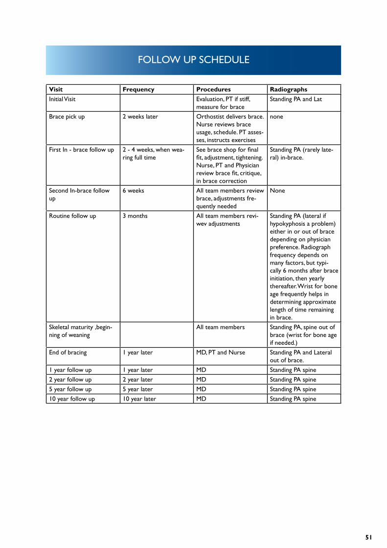
Visit Frequency Procedures Radiographs
Initial Visit Evaluation, PT if stiff, measure for brace
Standing PA and Lat
Brace pick up 2 weeks later Orthostist delivers brace. Nurse reviews brace usage, schedule. PT asses-ses, instructs exercises
none
First In - brace follow up 2 - 4 weeks, when wea-ring full time
See brace shop for final fit, adjustment, tightening. Nurse, PT and Physician review brace fit, critique, in brace correction
Standing PA (rarely late-ral) in-brace.
Second In-brace follow up
6 weeks All team members review brace, adjustments fre-quently needed
None
Routine follow up 3 months All team members revi-wev adjustments
Standing PA (lateral if hypokyphosis a problem) either in or out of brace depending on physician preference. Radiograph frequency depends on many factors, but typi-cally 6 months after brace initiation, then yearly thereafter. Wrist for bone age frequently helps in determining approximate length of time remaining in brace.
Skeletal maturity ,begin-ning of weaning
All team members Standing PA, spine out of brace (wrist for bone age if needed.)
End of bracing 1 year later MD, PT and Nurse Standing PA and Lateral out of brace.
1 year follow up 1 year later MD Standing PA spine
2 year follow up 2 year later MD Standing PA spine
5 year follow up 5 year later MD Standing PA spine
10 year follow up 10 year later MD Standing PA spine
52
TERMINOLOGY AND DEFINITIONS
ADAM’S FORWARD BENDING TEST: The standard screening exam for spinal asymmetry – the patient places their hands together and bends forward. The examiner sights along the spine looking for a rib or lumbar hump.
ADOLESCENT SCOLIOSIS: Spinal curvature presenting at or about onset of puberty and before maturity.
ADULT SCOLIOSIS: Spinal curvature existing after skeletal maturity.
ANGLE OF THORACIC INCLINATION: With the trunk flexed at 90° at the hip, the angle between horizontal and a plane across the posterior rib cage at the greatest prominence of the rib hump.
APICAL VERTEBRA: The most rotated vertebra in a curve; the most deviated vertebra from the vertical axis of the patient.
BODY ALIGNMENT, BALANCE, AND COMPENSATION: 1. The alignment of the midpoint of the occiput over the sacrum in the same vertical plane as the shoulders over the hips. 2. Roentgenology : When the sum of the angular deviations of the spine in one direction is equal to that in the opposite direction.
CAFÉ AU LAIT SPOTS: Light brown irregular areas of skin pigmentation. If sufficient in number and with smooth margins, they suggest neurofibromatosis.
CERVICAL CURVE: Spinal curvature that has its apex from C1 to C6.
CERVICO-THORACIC CURVE: Spinal curvature that has its apex at C7 or T1.
COMPENSATION: Accurate alignment of the midline of the skull over the midline of the sacrum.
COMPENSATORY CURVE: A curve, which can be structural, above or below a major curve, tends to maintain normal body alignment.
CONGENITAL SCOLIOSIS: Scoliosis due to congenitally anomalous vertebral development.

53
CURVE MEASUREMENT: Cobb method: Select the upper and lower end vertebrae. Erect perpendiculars to the transverse axes. They intersect to form the angle of the curve. If the vertebral endplates are poorly visualized, a line through the bottom or top pedicles may be used. Ferguson method: the angle of a curve is formed by the intersection of two lines drawn from the center of the superior and inferior end vertebral bodies to the center of the apical vertebral body.
DOUBLE STRUCTURAL CURVE. Double major scoliosis: A scoliosis with two structural curves. Two structural curves in the same spine, one balancing the other.
DOUBLE THORACIC CURVE (SCOLIOSIS): A scoliosis with a structural upper thoracic curve, a larger, more deforming lower thoracic curve,and a relatively non-structural lumbar curve.
END VERTEBRA: The most cephalad vertebra of a curve whose superior surface, or the most caudad vertebra whose inferior surface, tilts maximally toward the concavity of the curve.
FRACTIONAL CURVE: A compensatory curve that is incomplete because it returns to the erect. Its only horizontal vertebra is caudad or cephalad
FULL CURVE: A curve in which the only horizontal vertebra is at the apex.
FUNCTIONAL CURVE, NONSTRUCTURAL CURVE: A curve that has no structural component and that corrects or overcorrects on recumbent side bending radiographic views.
GENETIC SCOLIOSIS: A structural spinal curvature inherited according to genetic pattern.Gibbus: A sharply angular kyphosis.Hysterical scoliosis: A nonstructural deformity of the spine that develops as a manifestation of a conversion reaction.
IDIOPATHIC SCOLIOSIS: A structural spinal curvature for which no cause can be established.
ILIAC EPIPHYSIS, ILIAC APOPHYSIS: The epiphysis along the wing of the ilium.
ILIAC EPIPHYSIS SIGN, ILIAC APOPHYSIS SIGN: In the anterioposterior radiographic view of the spine, when the excursion of the ossification in the iliac epiphy-sis (apophysis) reaches its ultimate medical migration, vertebral growth may be complete.
INCLINOMETER: An instrument used to measure the angle of thoracic inclination or rib hump.
TERMINOLOGY AND DEFINITIONS
54
INFANTILE SCOLIOSIS: Spinal curvature that develops during the first three years of life.
JUVENILE SCOLIOSIS: Spinal curvature that develops between the skeletal age of three years and the onset of puberty.
KYPHOSIS: A change in the alignment of a segment of the spine in the sagittal plane that increases the posterior convex angulation
KYPHOSCOLIOSIS: lateral curvature of the spine associated with either increased posterior ordecreased anterior angulation in the sagittal plane in excess of the accepted norm for that region. In the thora-cic region 20 –40 degrees of kyphosis is considered normal.
LORDOSCOLIOSIS: Lateral curvature of the spine associated with the increase in anterior curvature or a decrease in the posterior spine angulation of the thoracic spine where posterior angulation is normally present, less than 20 degrees would constitute lordoscoliosis.
LUMBAR CURVE:Spinal curvature that has its apex from L1 to L4.
LUMBOSACRAL CURVE: Spinal curvature that has its Apex at L5 or below.
MAJOR CURVE: Term used to designate the larger (largest) curve (s), usually structural.
MINOR CURVE: Term used to refer to the smaller (smallest) curve (s).
MYORZENIC SCOLIOSIS: Spinal curvature due to disease or anomalies of the musculature.
NEUROGENIC SCOLIOSIS: Spinal curvature due to disease or anomalies of nerve tissue.
OSTEOGENIC SCOLIOSIS: Spinal curvature due to abnormality of the vertebral elements and or adjacent ribs, acquired or congenital.
PELVIC OBLIQUITY: Deviation of the pelvis from the horizontal in the frontal plane. Fixed pelvic obliquity’s can be attributable to contractures either above or below the pelvis.
PRIMARY CURVE: The first or earliest of several curves to appear, if identifiable.
TERMINOLOGY AND DEFINITIONS
55
RIB HUMP: The prominence of the ribs on the convexity of a spinal curvature, usually due to vertebral rotation best exhibi-ted on forward bending.
SKELETAL AGE, BONE AGE: The age obtained by comparing an anterioposterior radiographic view of the left hand and wrist with the stan-dards of the Greulich and Pyle Atlas.
STRUCTURAL CURVE: A segment of the spine with a fixed lateral curvature. Radiographically, it is identified in supine lateral side – bending views by failure to correct. They may be multiple.
THORACIC CURVE: Scoliosis in which the apex of the curvature is between T2 and T11.
THORACOGENIC SCOLIOSIS: Spinal curvature attributed to disease or operative trauma in or on the thoracic cage.
THORACOLUMBAR CURVE: Spinal curvature that has its apex at T12 or L1.
TRANSITIONAL VERTEBRA: Vertebra that is neutral in relation to rotation usually at the end of a curve.
VERTEBRAL ENDPLATES: The superior and inferior plates cortical bone of the vertebral body adjacent to the intervertebral disc.
VERTEBRAL GROWTH PLATE: The cartilaginous surface covering the top and bottom of the vertebral body that is responsible for linear growth of the vertebra.
VERTEBRAL RING APOPHYSES: The most reliable index of vertebral immaturity seen best in the lateral radiographs or in the lumbar region in side – bending anterioposterior views.
Bibliography for terminology:Goldstein LA. Waugh TR. Classification and terminology of scoliosis. Clin Orthop 1973:1022.McAlister WH, Shackelford GD. Classification of spinal curvatures. Radial Clin North Am 1975, 13:93-121.The Terminology Committee of the Scoliosis Research Society. A glossary of scoliosis terms. Spine 1976:1:57
TERMINOLOGY AND DEFINITIONS
56
MOST COMMON ADJUSTMENTS TO THE BOSTON SCOLIOSIS BRACE
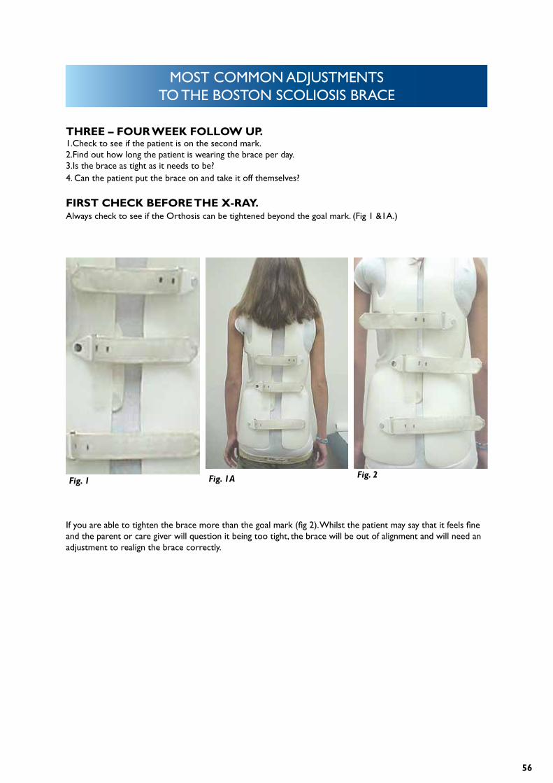
THREE – FOUR WEEK FOLLOW UP.1.Check to see if the patient is on the second mark.2.Find out how long the patient is wearing the brace per day.3.Is the brace as tight as it needs to be?4. Can the patient put the brace on and take it off themselves?
FIRST CHECK BEFORE THE X-RAY.Always check to see if the Orthosis can be tightened beyond the goal mark. (Fig 1 &1A.)
If you are able to tighten the brace more than the goal mark (fig 2). Whilst the patient may say that it feels fine and the parent or care giver will question it being too tight, the brace will be out of alignment and will need an adjustment to realign the brace correctly.
Fig. 1 Fig. 1A Fig. 2
57
MOST COMMON ADJUSTMENTS TO THE BOSTON SCOLIOSIS BRACE
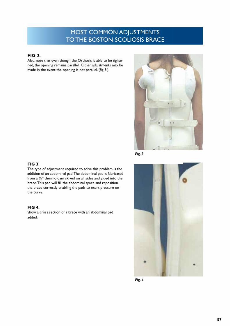
FIG 2. Also, note that even though the Orthosis is able to be tighte-ned, the opening remains parallel. Other adjustments may be made in the event the opening is not parallel. (fig 3.)
FIG 3.The type of adjustment required to solve this problem is the addition of an abdominal pad. The abdominal pad is fabricated from a ½” thermofoam skived on all sides and glued into the brace. This pad will fill the abdominal space and reposition the brace correctly enabling the pads to exert pressure on the curve.
FIG 4.Show a cross section of a brace with an abdominal pad added.
Fig. 3
Fig. 4
58
MOST COMMON ADJUSTMENTS TO THE BOSTON SCOLIOSIS BRACE
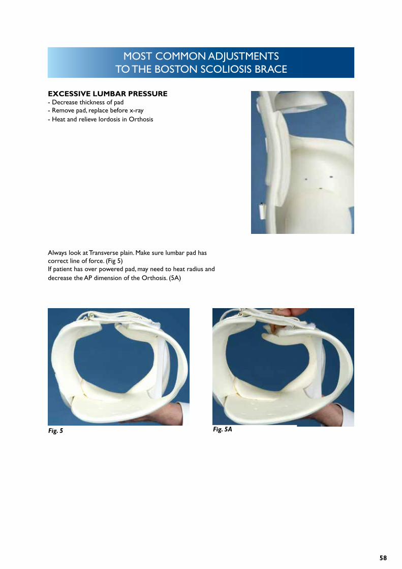
EXCESSIVE LUMBAR PRESSURE- Decrease thickness of pad- Remove pad, replace before x-ray- Heat and relieve lordosis in Orthosis
Always look at Transverse plain. Make sure lumbar pad has correct line of force. (Fig 5)If patient has over powered pad, may need to heat radius and decrease the AP dimension of the Orthosis. (5A)
Fig. 5 Fig. 5A
59
MOST COMMON ADJUSTMENTS TO THE BOSTON SCOLIOSIS BRACE
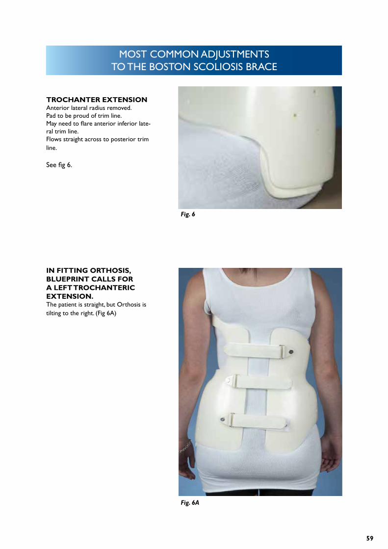
TROCHANTER EXTENSIONAnterior lateral radius removed.Pad to be proud of trim line.May need to flare anterior inferior late-ral trim line.Flows straight across to posterior trim line.
See fig 6.
IN FITTING ORTHOSIS, BLUEPRINT CALLS FOR A LEFT TROCHANTERIC EXTENSION.The patient is straight, but Orthosis is tilting to the right. (Fig 6A)
Fig. 6
Fig. 6A
60
MOST COMMON ADJUSTMENTS TO THE BOSTON SCOLIOSIS BRACE
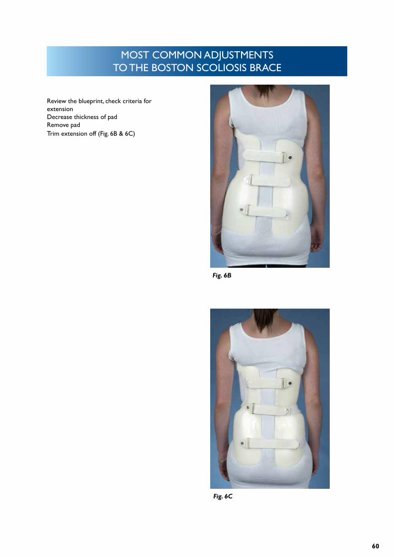
Review the blueprint, check criteria for extensionDecrease thickness of padRemove padTrim extension off (Fig. 6B & 6C)
Fig. 6B
Fig. 6C
61
MOST COMMON ADJUSTMENTS TO THE BOSTON SCOLIOSIS BRACE
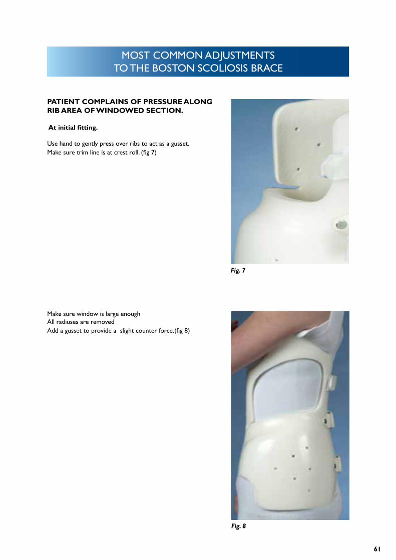
PATIENT COMPLAINS OF PRESSURE ALONG RIB AREA OF WINDOWED SECTION.
At initial fitting.
Use hand to gently press over ribs to act as a gusset.Make sure trim line is at crest roll. (fig 7)
Make sure window is large enoughAll radiuses are removedAdd a gusset to provide a slight counter force.(fig 8)
Fig. 7
Fig. 8
62
MOST COMMON ADJUSTMENTS TO THE BOSTON SCOLIOSIS BRACE
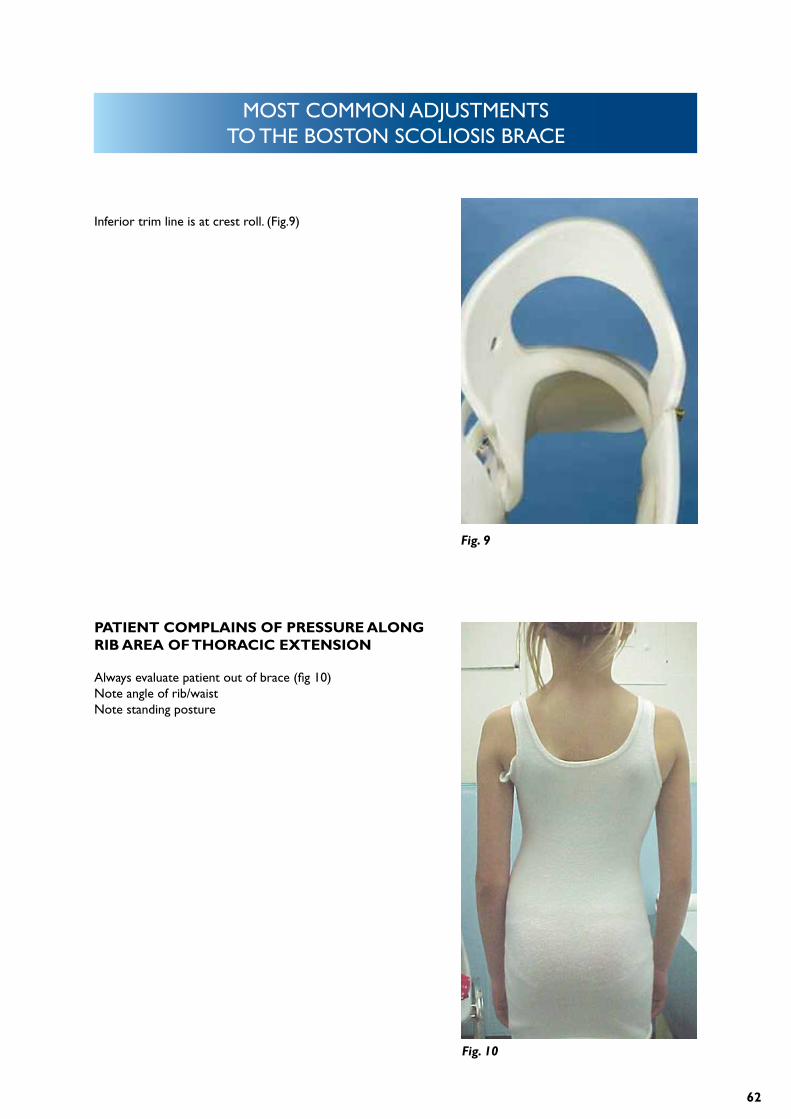
Inferior trim line is at crest roll. (Fig.9)
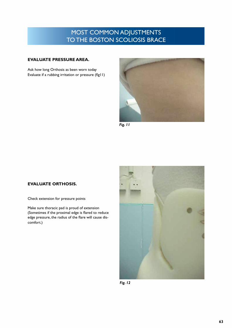
PATIENT COMPLAINS OF PRESSURE ALONG RIB AREA OF THORACIC EXTENSION
Always evaluate patient out of brace (fig 10)Note angle of rib/waistNote standing posture
Fig. 9
Fig. 10
63
MOST COMMON ADJUSTMENTS TO THE BOSTON SCOLIOSIS BRACE
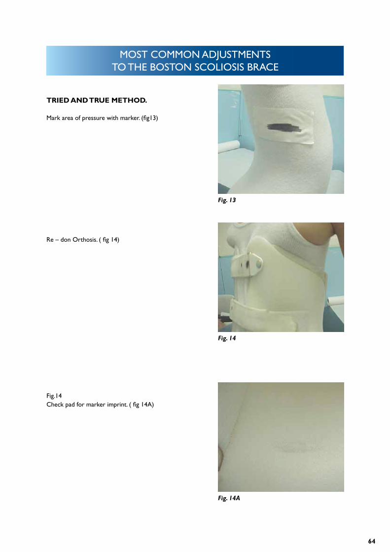
EVALUATE PRESSURE AREA.
Ask how long Orthosis as been worn todayEvaluate if a rubbing irritation or pressure (fig11)
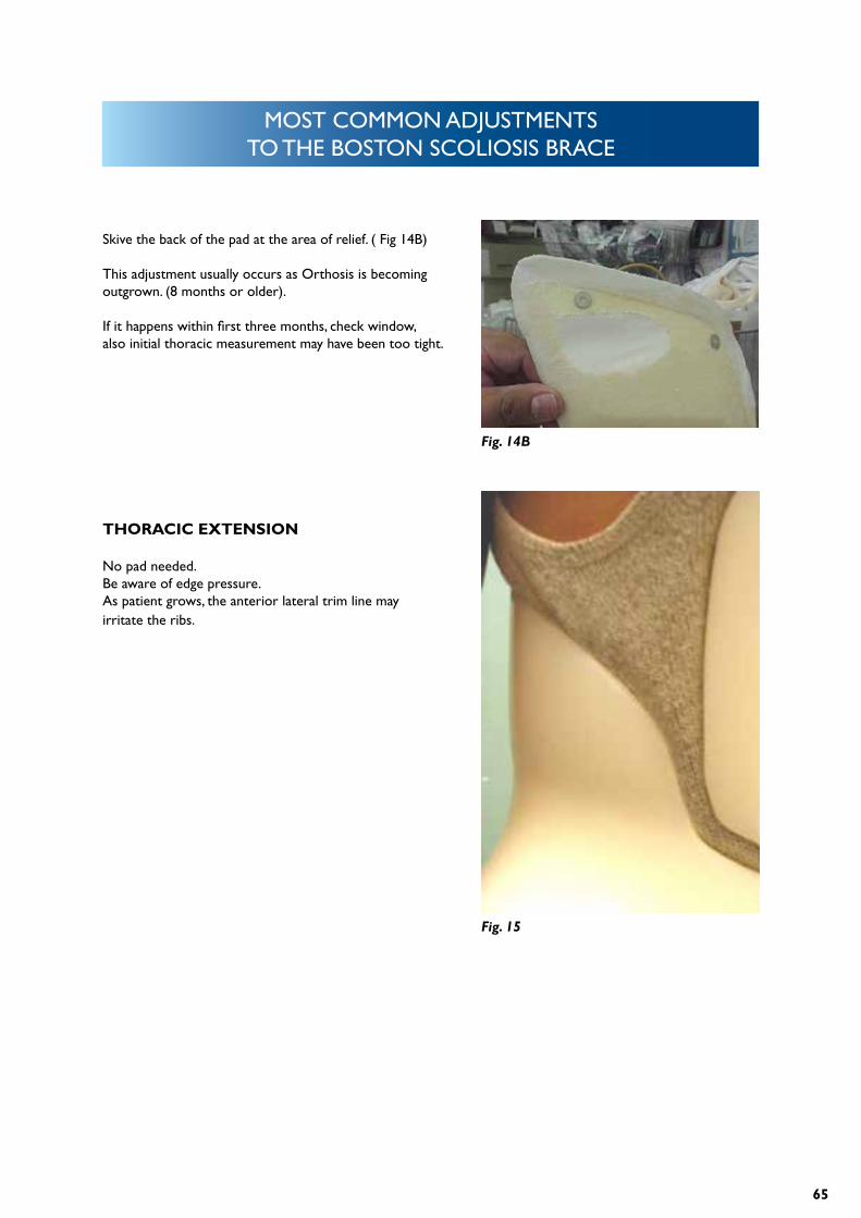
EVALUATE ORTHOSIS.
Check extension for pressure points
Make sure thoracic pad is proud of extension (Sometimes if the proximal edge is flared to reduce edge pressure, the radius of the flare will cause dis-comfort.)
Fig. 11
Fig. 12
64
MOST COMMON ADJUSTMENTS TO THE BOSTON SCOLIOSIS BRACE
TRIED AND TRUE METHOD.
Mark area of pressure with marker. (fig13)
Re – don Orthosis. ( fig 14)
Fig. 13
Fig. 14
Fig. 14A
Fig.14Check pad for marker imprint. ( fig 14A)
65
MOST COMMON ADJUSTMENTS TO THE BOSTON SCOLIOSIS BRACE
Skive the back of the pad at the area of relief. ( Fig 14B)
This adjustment usually occurs as Orthosis is becoming outgrown. (8 months or older).
If it happens within first three months, check window, also initial thoracic measurement may have been too tight.
THORACIC EXTENSION
No pad needed.Be aware of edge pressure.As patient grows, the anterior lateral trim line may irritate the ribs.
Fig. 14B
Fig. 15

66
For more information please visit www.allarduk.co.uk or contact us at [email protected].
ABOUT USAllard Support UK Ltd (previously Boston Brace Europe Ltd), continue to manufacture and
promote the original Boston Brace product range, which provide a proven philosophy based on
the foundation of evidence based medicine and vigorously supported by education and training.
Today, Allard Support UK Ltd supplies the Original Boston product range directly to our custo-
mers in the UK and through our distribution partners in Europe, Japan, Korea, India, and many
other countries. Visit www.allarduk.co.uk for information on distributors and our product range.
Apr
il 20
13