
Reference Guide for the Network Interface Controller Interface Controller for Tempered Air Products...
20
1 Network Interface Controller for Tempered Air Products Reference Guide for the Network Interface Controller Please read and save these instructions. Read carefully before attempting to operate or maintain the product described. Protect yourself and others by observing all safety practices. Failure to comply with instructions could result in personal injury and/or property damage! Retain instructions for future reference. Program Features The network interface controller is a device that acts as a communication link between the BMS (Building Management System) and the unit. The network interface controller will transform the communication into an action within the unit and will provide monitoring status of various functions and temperatures. The controller has the ability to communicate with a BMS through protocols such as LonWorks®, BACnet® MSTP, BACnet® IP or Modbus. See Points List at end of document for a complete list of BMS points. Introduction BMS v1.00 Version Date: May 24, 2011 Introduction . . . . . . . . . . . . . . . . . . . . . 1 Input/Output Points . . . . . . . . . . . . . . . . . 2 Alarms . . . . . . . . . . . . . . . . . . . . . . . . 2 Remote Display Panel (Optional) . . . . . . . . . . 2 Display Use . . . . . . . . . . . . . . . . . . . . . 2 Keypad Description . . . . . . . . . . . . . . . . . 3 Example of Parameter Adjustment . . . . . . . . . 3 Example of Alarms . . . . . . . . . . . . . . . . . 3 List of Possible Alarms . . . . . . . . . . . . . . . 4 Main Menu Overview . . . . . . . . . . . . . . . . 4 Menu Overview . . . . . . . . . . . . . . . . . . . 5 Menus A. Setpoint . . . . . . . . . . . . . . . . . . 6 B. Clock/Scheduler . . . . . . . . . . . . . . 6 C. Input/Output . . . . . . . . . . . . . . . . 6 D. Data Logger . . . . . . . . . . . . . . . . 6 E. Board Switch . . . . . . . . . . . . . . . 7 F. Service a. Information . . . . . . . . . . . . . . . . 7 b. Overrides . . . . . . . . . . . . . . . . . 7 c. BMS Config . . . . . . . . . . . . . . . 8-9 d. Service Settings . . . . . . . . . . . . . 9 a. Working hour set . . . . . . . . . . . . 9 b. Probe adjustment . . . . . . . . . . . 9 c. Password/Defaults . . . . . . . . . 9-10 G. Manufacturer a. Configuration . . . . . . . . . . . . . . . 10 b. I/O Configuration . . . . . . . . . . . . . 11 c. Factory Settings . . . . . . . . . . . . . 11 d. Initialization . . . . . . . . . . . . . . . . 11 Points List LonWorks® . . . . . . . . . . . . . . . . . . . . 12 ModBus/BACnet® . . . . . . . . . . . . . . . . 13 Typical Wiring Diagram . . . . . . . . . . . . . . . 14 Troubleshooting . . . . . . . . . . . . . . . . . . . 15 NTC Temperature Sensor Chart . . . . . . . . . . 15 BACnet® MSTP Quick Start . . . . . . . . . . . . 16 BACnet® IP/Eth Quick Start . . . . . . . . . . . . 17 Maintenance Log . . . . . . . . . . . . . . . . 18-19 Warranty . . . . . . . . . . . . . . . . . . . . . . . 20 Table of Contents ® ® Part #475262 Network Interface Controller for Tempered Air Products
Transcript of Reference Guide for the Network Interface Controller Interface Controller for Tempered Air Products...
1Network Interface Controller for Tempered Air Products
Reference Guide for the Network Interface ControllerPlease read and save these instructions. Read carefully before attempting to operate or maintain the product described. Protect yourself and others by observing all safety practices. Failure to comply with instructions could result in personal injury and/or property damage! Retain instructions for future reference.
Program FeaturesThe network interface controller is a device that acts as a communication link between the BMS (Building Management System) and the unit. The network interface controller will transform the communication into an action within the unit and will provide monitoring status of various functions and temperatures. The controller has the ability to communicate with a BMS through protocols such as LonWorks®, BACnet® MSTP, BACnet® IP or Modbus. See Points List at end of document for a complete list of BMS points.
Introduction
BMS v1.00Version Date: May 24, 2011 Introduction . . . . . . . . . . . . . . . . . . . . . 1
Input/Output Points . . . . . . . . . . . . . . . . . 2Alarms . . . . . . . . . . . . . . . . . . . . . . . . 2Remote Display Panel (Optional) . . . . . . . . . . 2Display Use . . . . . . . . . . . . . . . . . . . . . 2Keypad Description . . . . . . . . . . . . . . . . . 3Example of Parameter Adjustment . . . . . . . . . 3Example of Alarms . . . . . . . . . . . . . . . . . 3List of Possible Alarms . . . . . . . . . . . . . . . 4Main Menu Overview . . . . . . . . . . . . . . . . 4Menu Overview . . . . . . . . . . . . . . . . . . . 5Menus
A. Setpoint . . . . . . . . . . . . . . . . . . 6
B. Clock/Scheduler . . . . . . . . . . . . . . 6
C. Input/Output . . . . . . . . . . . . . . . . 6
D. Data Logger . . . . . . . . . . . . . . . . 6
E. Board Switch . . . . . . . . . . . . . . . 7
F. Servicea. Information . . . . . . . . . . . . . . . . 7b. Overrides . . . . . . . . . . . . . . . . . 7c. BMS Config . . . . . . . . . . . . . . . 8-9d. Service Settings . . . . . . . . . . . . . 9
a. Working hour set. . . . . . . . . . . . 9b. Probe adjustment . . . . . . . . . . . 9c. Password/Defaults . . . . . . . . .9-10
G. Manufacturera. Configuration . . . . . . . . . . . . . . . 10b. I/O Configuration . . . . . . . . . . . . . 11c. Factory Settings . . . . . . . . . . . . . 11d. Initialization . . . . . . . . . . . . . . . . 11
Points ListLonWorks® . . . . . . . . . . . . . . . . . . . . 12ModBus/BACnet® . . . . . . . . . . . . . . . . 13
Typical Wiring Diagram . . . . . . . . . . . . . . . 14Troubleshooting . . . . . . . . . . . . . . . . . . . 15NTC Temperature Sensor Chart . . . . . . . . . . 15BACnet® MSTP Quick Start . . . . . . . . . . . . 16BACnet® IP/Eth Quick Start . . . . . . . . . . . . 17Maintenance Log . . . . . . . . . . . . . . . . 18-19Warranty . . . . . . . . . . . . . . . . . . . . . . .20
Table of Contents
®
®
Part #475262Network Interface Controller for
Tempered Air Products

2 Network Interface Controller for Tempered Air Products
Input Points (Max 6) Output Points Digital (Max 5) Output Points Analog (Max 3)
Cold Coil Temp Call for Heat Stage 1 Heat Output
Return Air Temp Call for Cool Stage 1 Cool Output
Exhaust Discharge Temp Call for Cool Stage 2 Supply VFD
Outdoor Air After Wheel Temp Occupied Unoccupied Exhaust VFD
Dirty Filter Status Remote Exhaust Fan Energy Wheel VFD
Rotation Status Call for HGRH Return Air Damper
CO2 Sensor Alarm User Defined
Supply VFD Monitor Signal User Defined
Exhaust VFD Monitor Signal
User Defined
Input/Output PointsStandard Input/Output points are Supply Air Temp, Outside Air Temp and Fan Proving Status. The following are optional I/O points. See Network Interface unit diagram to see job specific I/O.
Display Use
The network interface controller is located in the unit control panel. The face of the controller has six keys, allowing the user to view unit conditions and alter parameters. The network interface controller is pre-programmed with easy-to-use menus.
The network interface controller will monitor the unit conditions for alarm conditions. Upon detecting an alarm, the controller will record the alarm description, time, date and available temperatures for user review. An optional digital output is available for remote alarm indication. Alarms are also communicated via BMS.
•Temperature Sensor Alarm: Network interface controller will send an alarm in the case of a failed air temperature sensor.
•Supply Air Low Limit: If the supply air temperature drops below the supply air low limit (35°F), the network interface controller can do one of the following based on user setup.
- Alarm Only: Sends alarm via BMS.- Alarm and Open NO3: Sends an alarm and turns
the unit run command off, even if BMS run command is active.
- Disable: Disables the supply air low limit function.
Alarms
Remote Display Panel (Optional)A display panel allows for remote monitoring and adjustment of parameters, allowing ease of control access without going outdoors.
A remote mounted display is also available, which connects via the J4 port. A six-wire patch cable is needed.
®

3Network Interface Controller for Tempered Air Products
Keypad Description
Prg Escor ! AlarmButton will blink red, indicating an alarm condition. Press to review current alarms. To review previous alarms, access the DATA LOGGER through the main menu.Prg Esc
Down Arrow The arrow keys allow the user to scroll through different screens and adjust
parameters.
Prg Esc
Up Arrow
Prg Esc
Enter
A. In screens with adjustable parameters, pressing the Enter key moves the cursor from the upper left corner of the screen to the parameter. The arrow keys can then be used to adjust the parameter.
B. To move to the next parameter on the same screen, press the Enter button.
C. To save the change, press the Enter button until the cursor moves back to the upper left corner of the screen.
Prg Esc or ! Escape Allows the user to exit the current menu, jumping to the Main Menu.
Prg Escor ! ProgramPressing the Prg (Program) button allows the user to enter the Main Program Menu. See below for Main Program Menu description.
Example of Parameter Adjustment
The cursor always begins in the upper left corner of the display and will be
blinking. Press the
Prg Esc
key to move the cursor down for parameter adjustment.
Once the cursor has reached the desired parameter, press the
Prg Esc
Prg Esc
keys to adjust the value.
When satisfied with the adjustment, press the
Prg Esc
key to save the parameter. When finished, make certain the cursor is in the upper left corner. If the cursor is not in the upper left corner, the changes will not be saved. The cursor must be in the upper left corner to enable screen advancement.
Supply air low limit
Alarm when supply is below: 35.0º FAlarm delay: 300s
Supply air low limit
Alarm when supply is below: 32.0º FAlarm delay: 300s
Supply air low limit
Alarm when supply is below: 32.0º FAlarm delay: 300s
Examples of Alarms
If an alarm occurs, the status line will state !PRESS ALARM BUTTON! and the Prg Esc or ! button will glow red on the controller and the remote display (if installed).
This is an example of an outdoor air sensor failure.
This screen appears if there are no active alarms.
To view all saved alarms, press the
Prg Esc
button to enter the DATA LOGGER. For more information, see the Data Logger menu.
Alarms
Press DOWN to review current alarm(s).Press ESC to exit.Press ALARM to reset.
Alarms
No active alarm
Press ENTER to DATA LOGGER
B3-Outdoor Temp Sensor B03 Failure
To view alarm, press the Prg Esc or ! button once. This will display the most
recent alarm. Press the Prg Esc or ! button again to reset the alarm. If the alarm cannot be cleared, the cause of the alarm has not been fixed. Press the
Prg Esc
Prg Esc
buttons to view any additional occurring alarms.
®
4 Network Interface Controller for Tempered Air Products
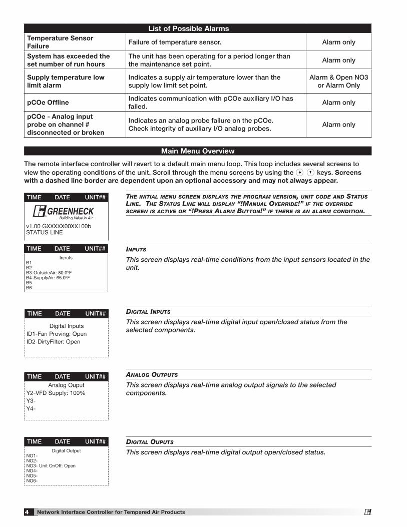
List of Possible AlarmsTemperature Sensor Failure
Failure of temperature sensor. Alarm only
System has exceeded the set number of run hours
The unit has been operating for a period longer than the maintenance set point.
Alarm only
Supply temperature low limit alarm
Indicates a supply air temperature lower than the supply low limit set point.
Alarm & Open NO3 or Alarm Only
pCOe OfflineIndicates communication with pCOe auxiliary I/O has failed.
Alarm only
pCOe - Analog input probe on channel # disconnected or broken
Indicates an analog probe failure on the pCOe. Check integrity of auxiliary I/O analog probes.
Alarm only
Inputs
This screen displays real-time conditions from the input sensors located in the unit.
DIgItal Inputs
This screen displays real-time digital input open/closed status from the selected components.
analog outputs
This screen displays real-time analog output signals to the selected components.
TIME DATE UNIT##
Digital InputsID1-Fan Proving: OpenID2-DirtyFilter: Open
TIME DATE UNIT##Analog Ouput
Y2-VFD Supply: 100%Y3-Y4-
TIME DATE UNIT##Digital Output
NO1-NO2-NO3- Unit OnOff: OpenNO4-NO5-NO6-
DIgItal ouputs
This screen displays real-time digital output open/closed status.
TIME DATE UNIT##Inputs
B1-B2-B3-OutsideAir: 80.0ºFB4-SupplyAir: 65.0ºFB5-B6-
The remote interface controller will revert to a default main menu loop. This loop includes several screens to view the operating conditions of the unit. Scroll through the menu screens by using the
Prg Esc
Prg Esc
keys. Screens with a dashed line border are dependent upon an optional accessory and may not always appear.
the InItIal menu screen DIsplays the program versIon, unIt coDe anD status lIne. the status lIne wIll DIsplay “!manual overrIDe!” If the overrIDe screen Is actIve or “!press alarm Button!” If there Is an alarm conDItIon.
Main Menu Overview
TIME DATE UNIT##
v1.00 GXXXXX00XX100b STATUS LINE
®
®
5Network Interface Controller for Tempered Air Products
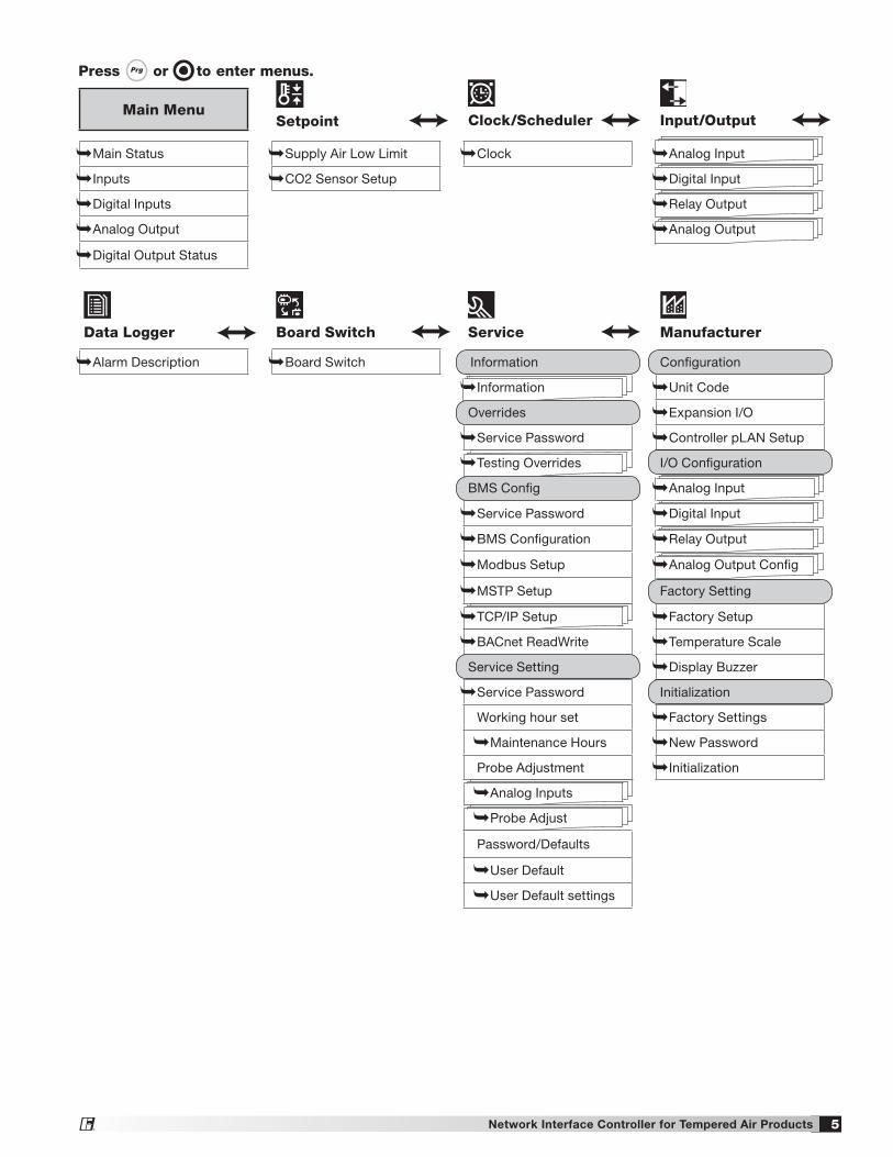
Press Prg Esc or! to enter menus.
Main MenuSetpoint Clock/Scheduler Input/Output
Main Status Supply Air Low Limit Clock Analog Input
Inputs CO2 Sensor Setup Digital Input
Digital Inputs Relay Output
Analog Output Analog Output
Digital Output Status
Data Logger Board Switch Service Manufacturer
Alarm Description Board Switch Information Configuration
Information Unit Code
Overrides Expansion I/O
Service Password Controller pLAN Setup
Testing Overrides I/O Configuration
BMS Config Analog Input
Service Password Digital Input
BMS Configuration Relay Output
Modbus Setup Analog Output Config
MSTP Setup Factory Setting
TCP/IP Setup Factory Setup
BACnet ReadWrite Temperature Scale
Service Setting Display Buzzer
Service Password Initialization
Working hour set Factory Settings
Maintenance Hours New Password
Probe Adjustment Initialization
Analog Inputs
Probe Adjust
Password/Defaults
User Default
User Default settings
®
6 Network Interface Controller for Tempered Air Products
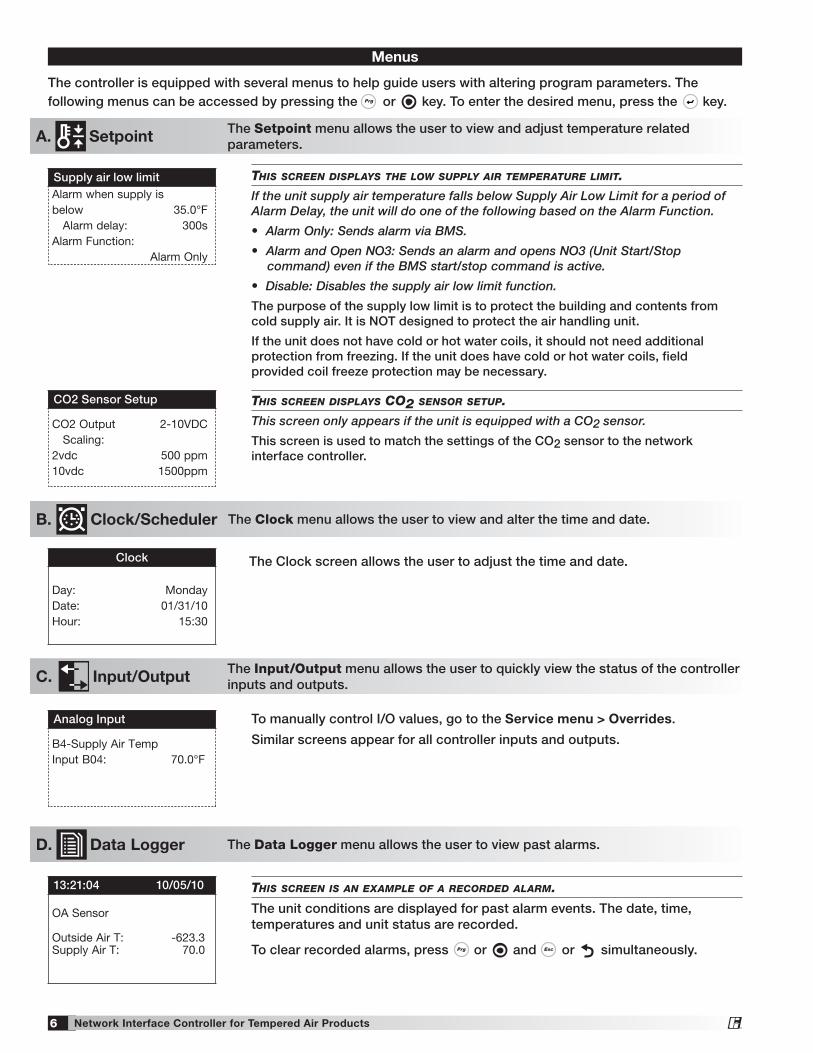
The controller is equipped with several menus to help guide users with altering program parameters. The following menus can be accessed by pressing the Prg Esc or ! key. To enter the desired menu, press the
Prg Esc
key.
The Setpoint menu allows the user to view and adjust temperature related parameters.
thIs screen DIsplays the low supply aIr temperature lImIt.
If the unit supply air temperature falls below Supply Air Low Limit for a period of Alarm Delay, the unit will do one of the following based on the Alarm Function.
• Alarm Only: Sends alarm via BMS.
• Alarm and Open NO3: Sends an alarm and opens NO3 (Unit Start/Stop command) even if the BMS start/stop command is active.
• Disable: Disables the supply air low limit function.
The purpose of the supply low limit is to protect the building and contents from cold supply air. It is NOT designed to protect the air handling unit.
If the unit does not have cold or hot water coils, it should not need additional protection from freezing. If the unit does have cold or hot water coils, field provided coil freeze protection may be necessary.
thIs screen DIsplays co2 sensor setup.
This screen only appears if the unit is equipped with a CO2 sensor.
This screen is used to match the settings of the CO2 sensor to the network interface controller.
Menus
Supply air low limitAlarm when supply is below 35.0°F Alarm delay: 300sAlarm Function: Alarm Only
CO2 Sensor Setup
CO2 Output 2-10VDC Scaling:2vdc 500 ppm10vdc 1500ppm
A. Setpoint
The Clock screen allows the user to adjust the time and date.Clock
Day: MondayDate: 01/31/10Hour: 15:30
The Clock/Scheduler menu allows the user to view and alter the time and date. B. Clock/Scheduler
D. Data Logger
To manually control I/O values, go to the Service menu > Overrides.
Similar screens appear for all controller inputs and outputs.
thIs screen Is an example of a recorDeD alarm.
The unit conditions are displayed for past alarm events. The date, time, temperatures and unit status are recorded.
To clear recorded alarms, press Prg Esc or ! and Prg Esc or ! simultaneously.
Analog Input
B4-Supply Air TempInput B04: 70.0°F
13:21:04 10/05/10
OA Sensor Outside Air T: -623.3 Supply Air T: 70.0
C. Input/Output The Input/Output menu allows the user to quickly view the status of the controller inputs and outputs.
The Data Logger menu allows the user to view past alarms.
The Clock menu allows the user to view and alter the time and date.
The Setpoint menu allows the user to view and adjust temperature related parameters.
®
7Network Interface Controller for Tempered Air Products
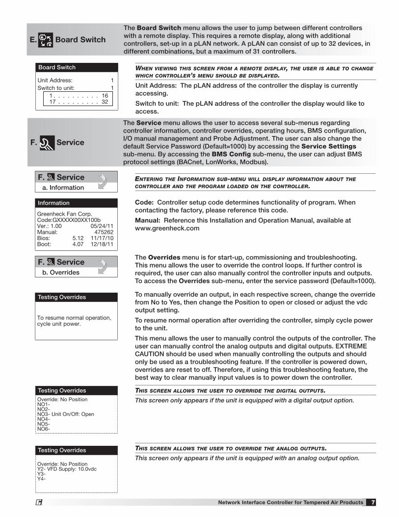
E. Board Switch
The Board Switch menu allows the user to jump between different controllers with a remote display. This requires a remote display, along with additional controllers, set-up in a pLAN network. A pLAN can consist of up to 32 devices, in different combinations, but a maximum of 31 controllers.
when vIewIng thIs screen from a remote DIsplay, the user Is aBle to change whIch controller’s menu shoulD Be DIsplayeD.
Unit Address: The pLAN address of the controller the display is currently accessing.
Switch to unit: The pLAN address of the controller the display would like to access.
Board Switch
Unit Address: 1Switch to unit: 1 1 . . . . . . . . . . 16 17 . . . . . . . . . 32
The Overrides menu is for start-up, commissioning and troubleshooting. This menu allows the user to override the control loops. If further control is required, the user can also manually control the controller inputs and outputs. To access the Overrides sub-menu, enter the service password (Default=1000).
To manually override an output, in each respective screen, change the override from No to Yes, then change the Position to open or closed or adjust the vdc output setting.
To resume normal operation after overriding the controller, simply cycle power to the unit.
This menu allows the user to manually control the outputs of the controller. The user can manually control the analog outputs and digital outputs. EXTREME CAUTION should be used when manually controlling the outputs and should only be used as a troubleshooting feature. If the controller is powered down, overrides are reset to off. Therefore, if using this troubleshooting feature, the best way to clear manually input values is to power down the controller.
F. Service
enterIng the InformatIon suB-menu wIll DIsplay InformatIon aBout the controller anD the program loaDeD on the controller.
Code: Controller setup code determines functionality of program. When contacting the factory, please reference this code.
Manual: Reference this Installation and Operation Manual, available at www.greenheck.com
The Service menu allows the user to access several sub-menus regarding controller information, controller overrides, operating hours, BMS configuration, I/O manual management and Probe Adjustment. The user can also change the default Service Password (Default=1000) by accessing the Service Settings sub-menu. By accessing the BMS Config sub-menu, the user can adjust BMS protocol settings (BACnet, LonWorks, Modbus).
Information
Greenheck Fan Corp. Code:GXXXXX00XX100b Ver.: 1.00 05/24/11 Manual: 475262 Bios: 5.12 11/17/10 Boot: 4.07 12/18/11
Testing Overrides
To resume normal operation, cycle unit power.
F. Servicea. Information
F. Serviceb. Overrides
thIs screen allows the user to overrIDe the DIgItal outputs.
This screen only appears if the unit is equipped with a digital output option.
thIs screen allows the user to overrIDe the analog outputs.
This screen only appears if the unit is equipped with an analog output option.
Testing Overrides
Override: No PositionNO1-NO2-NO3- Unit On/Off: OpenNO4-NO5-NO6-
Testing Overrides
Override: No PositionY2- VFD Supply: 10.0vdcY3-Y4-
®
8 Network Interface Controller for Tempered Air Products
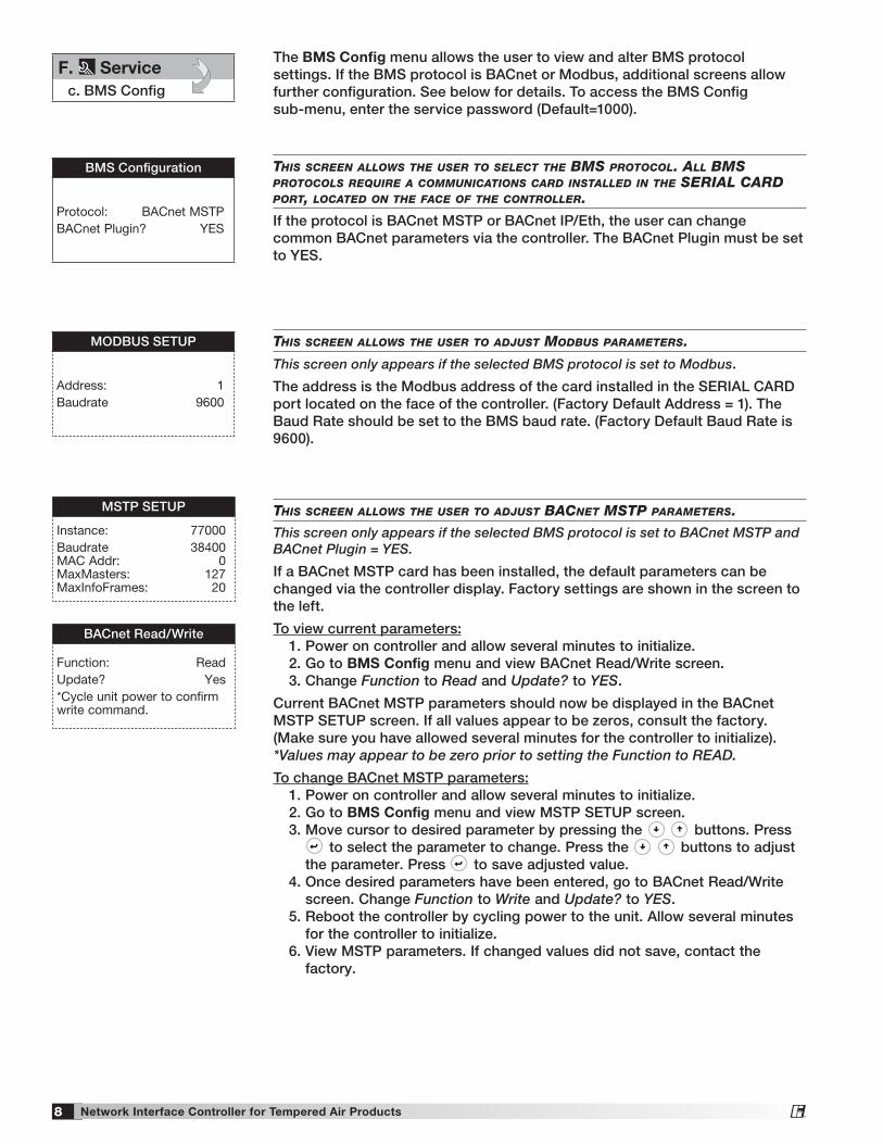
thIs screen allows the user to select the Bms protocol. all Bms protocols requIre a communIcatIons carD InstalleD In the serIal carD port, locateD on the face of the controller.
If the protocol is BACnet MSTP or BACnet IP/Eth, the user can change common BACnet parameters via the controller. The BACnet Plugin must be set to YES.
thIs screen allows the user to aDjust moDBus parameters.
This screen only appears if the selected BMS protocol is set to Modbus.
The address is the Modbus address of the card installed in the SERIAL CARD port located on the face of the controller. (Factory Default Address = 1). The Baud Rate should be set to the BMS baud rate. (Factory Default Baud Rate is 9600).
BMS Configuration
Protocol: BACnet MSTPBACnet Plugin? YES
MODBUS SETUP
Address: 1Baudrate 9600
F. Servicec. BMS Config
thIs screen allows the user to aDjust Bacnet mstp parameters.
This screen only appears if the selected BMS protocol is set to BACnet MSTP and BACnet Plugin = YES.
If a BACnet MSTP card has been installed, the default parameters can be changed via the controller display. Factory settings are shown in the screen to the left.
To view current parameters: 1. Power on controller and allow several minutes to initialize. 2. Go to BMS Config menu and view BACnet Read/Write screen. 3. Change Function to Read and Update? to YES.
Current BACnet MSTP parameters should now be displayed in the BACnet MSTP SETUP screen. If all values appear to be zeros, consult the factory. (Make sure you have allowed several minutes for the controller to initialize). *Values may appear to be zero prior to setting the Function to READ.
To change BACnet MSTP parameters: 1. Power on controller and allow several minutes to initialize. 2. Go to BMS Config menu and view MSTP SETUP screen. 3. Move cursor to desired parameter by pressing the
Prg Esc
Prg Esc
buttons. Press Prg Esc
to select the parameter to change. Press the
Prg Esc
Prg Esc
buttons to adjust the parameter. Press
Prg Esc
to save adjusted value. 4. Once desired parameters have been entered, go to BACnet Read/Write
screen. Change Function to Write and Update? to YES. 5. Reboot the controller by cycling power to the unit. Allow several minutes
for the controller to initialize. 6. View MSTP parameters. If changed values did not save, contact the
factory.
MSTP SETUP
Instance: 77000Baudrate 38400 MAC Addr: 0 MaxMasters: 127 MaxInfoFrames: 20
BACnet Read/Write
Function: ReadUpdate? Yes*Cycle unit power to confirm write command.
The BMS Config menu allows the user to view and alter BMS protocol settings. If the BMS protocol is BACnet or Modbus, additional screens allow further configuration. See below for details. To access the BMS Config sub-menu, enter the service password (Default=1000).
®
9Network Interface Controller for Tempered Air Products
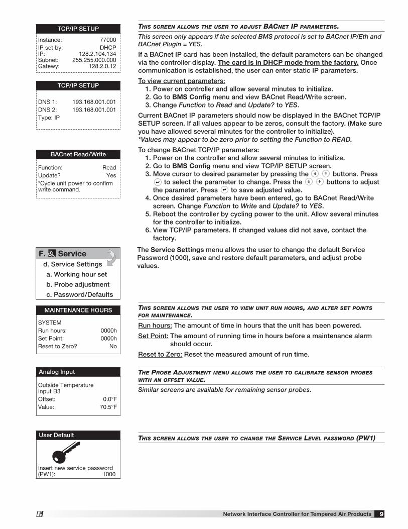
thIs screen allows the user to aDjust Bacnet Ip parameters.
This screen only appears if the selected BMS protocol is set to BACnet IP/Eth and BACnet Plugin = YES.
If a BACnet IP card has been installed, the default parameters can be changed via the controller display. The card is in DHCP mode from the factory. Once communication is established, the user can enter static IP parameters.
To view current parameters: 1. Power on controller and allow several minutes to initialize. 2. Go to BMS Config menu and view BACnet Read/Write screen. 3. Change Function to Read and Update? to YES.
Current BACnet IP parameters should now be displayed in the BACnet TCP/IP SETUP screen. If all values appear to be zeros, consult the factory. (Make sure you have allowed several minutes for the controller to initialize).*Values may appear to be zero prior to setting the Function to READ.
To change BACnet TCP/IP parameters: 1. Power on the controller and allow several minutes to initialize. 2. Go to BMS Config menu and view TCP/IP SETUP screen. 3. Move cursor to desired parameter by pressing the
Prg Esc
Prg Esc
buttons. Press Prg Esc
to select the parameter to change. Press the
Prg Esc
Prg Esc
buttons to adjust the parameter. Press
Prg Esc
to save adjusted value. 4. Once desired parameters have been entered, go to BACnet Read/Write
screen. Change Function to Write and Update? to YES. 5. Reboot the controller by cycling power to the unit. Allow several minutes
for the controller to initialize. 6. View TCP/IP parameters. If changed values did not save, contact the
factory.
TCP/IP SETUP
Instance: 77000IP set by: DHCP IP: 128.2.104.134 Subnet: 255.255.000.000 Gatewy: 128.2.0.12
TCP/IP SETUP
DNS 1: 193.168.001.001DNS 2: 193.168.001.001Type: IP
BACnet Read/Write
Function: ReadUpdate? Yes*Cycle unit power to confirm write command.
F. Serviced. Service Settings
a. Working hour set
b. Probe adjustment
c. Password/Defaults
The Service Settings menu allows the user to change the default Service Password (1000), save and restore default parameters, and adjust probe values.
thIs screen allows the user to vIew unIt run hours, anD alter set poInts for maIntenance.
Run hours: The amount of time in hours that the unit has been powered.
Set Point: The amount of running time in hours before a maintenance alarm should occur.
Reset to Zero: Reset the measured amount of run time.
the proBe aDjustment menu allows the user to calIBrate sensor proBes wIth an offset value.
Similar screens are available for remaining sensor probes.
thIs screen allows the user to change the servIce level passworD (pw1)
MAINTENANCE HOURS
SYSTEMRun hours: 0000hSet Point: 0000hReset to Zero? No
Analog Input
Outside Temperature Input B3Offset: 0.0°FValue: 70.5°F
User Default
Insert new service password (PW1): 1000
®
10 Network Interface Controller for Tempered Air Products
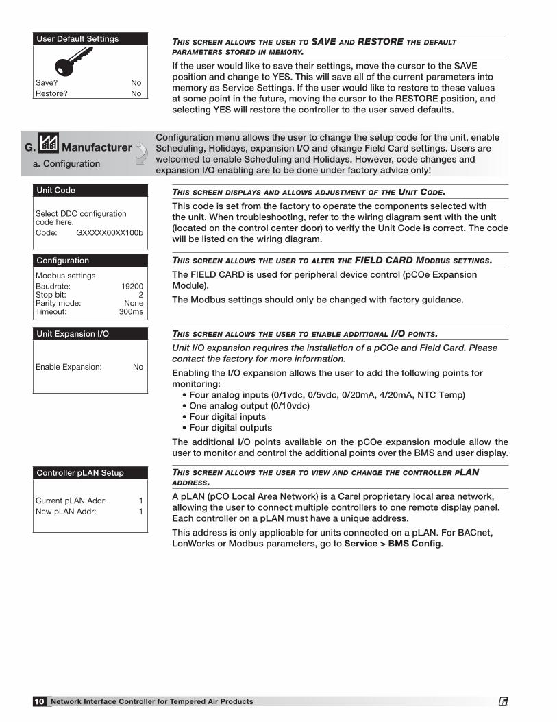
thIs screen allows the user to save anD restore the Default parameters storeD In memory.
If the user would like to save their settings, move the cursor to the SAVE position and change to YES. This will save all of the current parameters into memory as Service Settings. If the user would like to restore to these values at some point in the future, moving the cursor to the RESTORE position, and selecting YES will restore the controller to the user saved defaults.
User Default Settings
Save? NoRestore? No
G. Manufacturera. Configuration
Configuration menu allows the user to change the setup code for the unit, enable Scheduling, Holidays, expansion I/O and change Field Card settings. Users are welcomed to enable Scheduling and Holidays. However, code changes and expansion I/O enabling are to be done under factory advice only!
thIs screen DIsplays anD allows aDjustment of the unIt coDe.
This code is set from the factory to operate the components selected with the unit. When troubleshooting, refer to the wiring diagram sent with the unit (located on the control center door) to verify the Unit Code is correct. The code will be listed on the wiring diagram.
thIs screen allows the user to enaBle aDDItIonal I/o poInts.
Unit I/O expansion requires the installation of a pCOe and Field Card. Please contact the factory for more information.
Enabling the I/O expansion allows the user to add the following points for monitoring: •Fouranaloginputs(0/1vdc,0/5vdc,0/20mA,4/20mA,NTCTemp) •Oneanalogoutput(0/10vdc) •Fourdigitalinputs •Fourdigitaloutputs
The additional I/O points available on the pCOe expansion module allow the user to monitor and control the additional points over the BMS and user display.
thIs screen allows the user to vIew anD change the controller plan aDDress.
A pLAN (pCO Local Area Network) is a Carel proprietary local area network, allowing the user to connect multiple controllers to one remote display panel. Each controller on a pLAN must have a unique address.
This address is only applicable for units connected on a pLAN. For BACnet, LonWorks or Modbus parameters, go to Service > BMS Config.
thIs screen allows the user to alter the fIelD carD moDBus settIngs.
The FIELD CARD is used for peripheral device control (pCOe Expansion Module).
The Modbus settings should only be changed with factory guidance.
Unit Code
Select DDC configuration code here.Code: GXXXXX00XX100b
Configuration
Modbus settingsBaudrate: 19200 Stop bit: 2 Parity mode: None Timeout: 300ms
Unit Expansion I/O
Enable Expansion: No
Controller pLAN Setup
Current pLAN Addr: 1New pLAN Addr: 1
®
11Network Interface Controller for Tempered Air Products
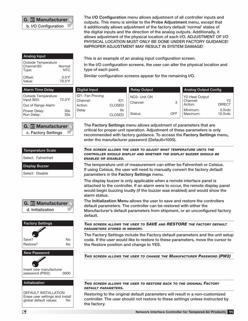
The I/O Configuration menu allows adjustment of all controller inputs and outputs. This menu is similar to the Probe Adjustment menu, except that it additionally allows adjustment of the factory default ‘normal’ states of the digital inputs and the direction of the analog outputs. Additionally, it allows adjustment of the physical location of each I/O. ADJUSTMENT OF I/O PHYSICAL LOCATION MUST ONLY BE DONE UNDER FACTORY GUIDANCE! IMPROPER ADJUSTMENT MAY RESULT IN SYSTEM DAMAGE!
This is an example of an analog input configuration screen.
In the I/O configuration screens, the user can alter the physical location and type of each point.
Similar configuration screens appear for the remaining I/O.
Analog Input
Outside Temperature Channel:B3 Normal Type: NTC
Offset: 0.0°F Value: 70.5°F
Alarm Time Delay
Outside Temperature Input B03: 72.0°F
Out of Range Alarm
Power Delay: 30s Run Delay: 30s
Digital Input
ID1- Fan ProvingChannel: ID1Action: CLOSEDDelay 0s CLOSED
Analog Output Config
Y2-Heat Output Channel: Y2 Action: DIRECT
Minimum: 0.0vdc Maximum: 10.0vdc
Relay Output
NO3- Unit ON
Channel: 3
Status: OFF
G. Manufacturerb. I/O Configuration
thIs screen allows the user to aDjust what temperature unIts the controller shoulD DIsplay anD whether the DIsplay Buzzer shoulD Be enaBleD or DIsaBleD.
The temperature unit of measurement can either be Fahrenheit or Celsius. If using Celsius, the user will need to manually convert the factory default parameters in the Factory Settings menu.
The display buzzer is only applicable when a remote interface panel is attached to the controller. If an alarm were to occur, the remote display panel would begin buzzing loudly (if the buzzer was enabled) and would show the alarm status.
Temperature Scale
Select: Fahrenheit
Display Buzzer
Select: Disable
The Factory Settings menu allows adjustment of parameters that are critical for proper unit operation. Adjustment of these parameters is only recommended with factory guidance. To access the Factory Settings menu, enter the manufacturer password (Default=1000).
G. Manufacturerc. Factory Settings
thIs screen allows the user to save anD restore the factory Default parameters storeD In memory.
The Factory Settings include the Factory default parameters and the unit setup code. If the user would like to restore to these parameters, move the cursor to the Restore position and change to YES.
thIs screen allows the user to restore Back to the orIgInal factory Default parameters.
Restoring to the original default parameters will result in a non-customized controller. The user should not restore to these settings unless instructed by the factory.
thIs screen allows the user to change the manufacturer passworD (pw2)
The Initialization Menu allows the user to save and restore the controllers default parameters. The controller can be restored with either the Manufacturer’s default parameters from shipment, or an unconfigured factory default.
Factory Settings
Save? NoRestore? No
New Password
Insert new manufacturer password (PW2): 0000
Initialization
DEFAULT INSTALLATION Erase user settings and install global default values: No
G. Manufacturerd. Initialization
®
12 Network Interface Controller for Tempered Air Products
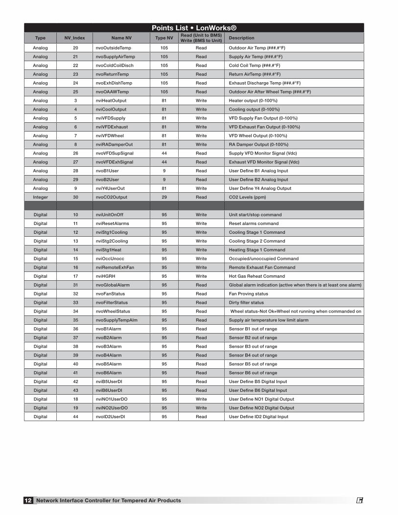
Points List • LonWorks®Type NV_Index Name NV Type NV
Read (Unit to BMS)Write (BMS to Unit)
Description
Analog 20 nvoOutsideTemp 105 Read Outdoor Air Temp (###.#°F)
Analog 21 nvoSupplyAirTemp 105 Read Supply Air Temp (###.#°F)
Analog 22 nvoColdCoilDisch 105 Read Cold Coil Temp (###.#°F)
Analog 23 nvoReturnTemp 105 Read Return AirTemp (###.#°F)
Analog 24 nvoExhDishTemp 105 Read Exhaust Discharge Temp (###.#°F)
Analog 25 nvoOAAWTemp 105 Read Outdoor Air After Wheel Temp (###.#°F)
Analog 3 nviHeatOutput 81 Write Heater output (0-100%)
Analog 4 nviCoolOutput 81 Write Cooling output (0-100%)
Analog 5 nviVFDSupply 81 Write VFD Supply Fan Output (0-100%)
Analog 6 nviVFDExhaust 81 Write VFD Exhaust Fan Output (0-100%)
Analog 7 nviVFDWheel 81 Write VFD Wheel Output (0-100%)
Analog 8 nviRADamperOut 81 Write RA Damper Output (0-100%)
Analog 26 nvoVFDSupSignal 44 Read Supply VFD Monitor Signal (Vdc)
Analog 27 nvoVFDExhSignal 44 Read Exhaust VFD Monitor Signal (Vdc)
Analog 28 nvoB1User 9 Read User Define B1 Analog Input
Analog 29 nvoB2User 9 Read User Define B2 Analog Input
Analog 9 nviY4UserOut 81 Write User Define Y4 Analog Output
Integer 30 nvoCO2Output 29 Read CO2 Levels (ppm)
Digital 10 nviUnitOnOff 95 Write Unit start/stop command
Digital 11 nviResetAlarms 95 Write Reset alarms command
Digital 12 nviStg1Cooling 95 Write Cooling Stage 1 Command
Digital 13 nviStg2Cooling 95 Write Cooling Stage 2 Command
Digital 14 nviStg1Heat 95 Write Heating Stage 1 Command
Digital 15 nviOccUnocc 95 Write Occupied/unoccupied Command
Digital 16 nviRemoteExhFan 95 Write Remote Exhaust Fan Command
Digital 17 nviHGRH 95 Write Hot Gas Reheat Command
Digital 31 nvoGlobalAlarm 95 Read Global alarm indication (active when there is at least one alarm)
Digital 32 nvoFanStatus 95 Read Fan Proving status
Digital 33 nvoFilterStatus 95 Read Dirty filter status
Digital 34 nvoWheelStatus 95 Read Wheel status-Not Ok=Wheel not running when commanded on
Digital 35 nvoSupplyTempAlm 95 Read Supply air temperature low limit alarm
Digital 36 nvoB1Alarm 95 Read Sensor B1 out of range
Digital 37 nvoB2Alarm 95 Read Sensor B2 out of range
Digital 38 nvoB3Alarm 95 Read Sensor B3 out of range
Digital 39 nvoB4Alarm 95 Read Sensor B4 out of range
Digital 40 nvoB5Alarm 95 Read Sensor B5 out of range
Digital 41 nvoB6Alarm 95 Read Sensor B6 out of range
Digital 42 nviB5UserDI 95 Read User Define B5 Digital Input
Digital 43 nviB6UserDI 95 Read User Define B6 Digital Input
Digital 18 nviNO1UserDO 95 Write User Define NO1 Digital Output
Digital 19 nviNO2UserDO 95 Write User Define NO2 Digital Output
Digital 44 nvoID2UserDI 95 Read User Define ID2 Digital Input
®
13Network Interface Controller for Tempered Air Products
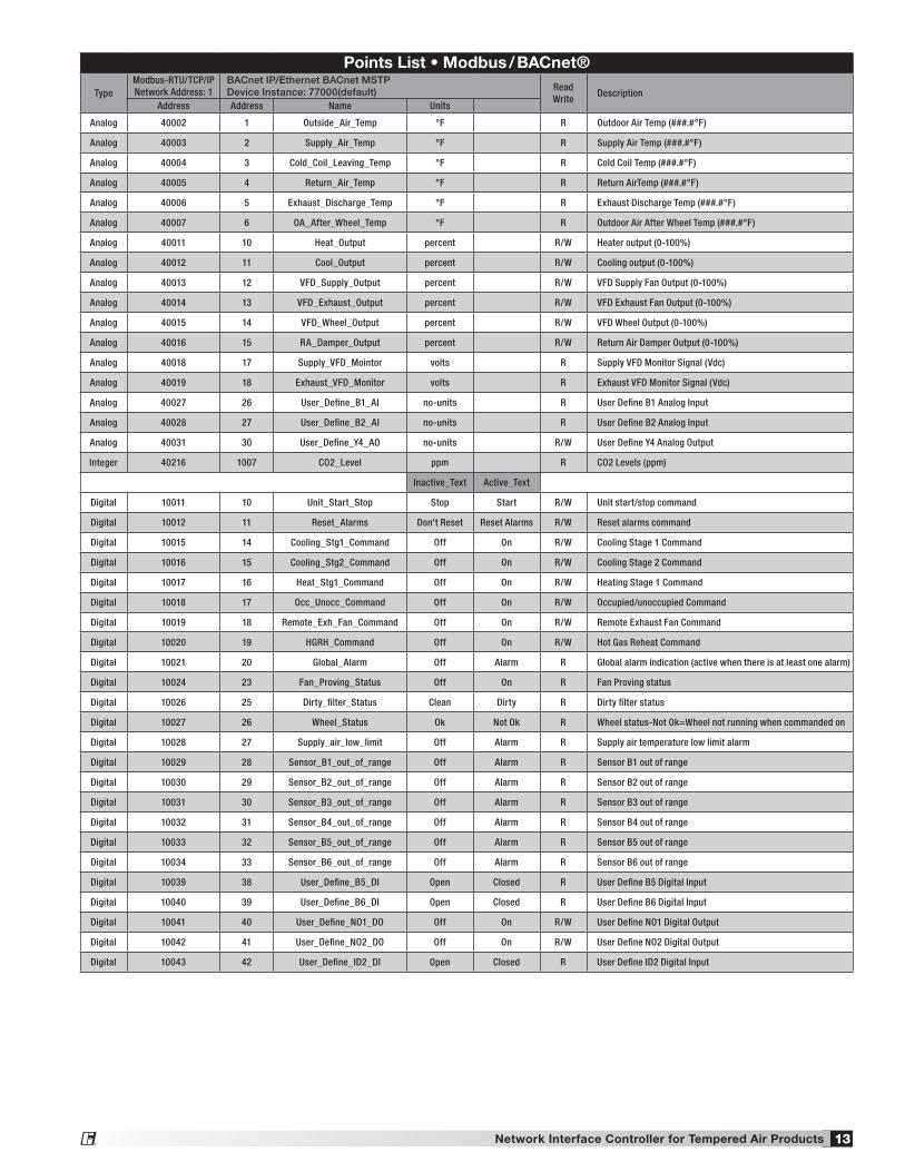
Points List • Modbus / BACnet®
TypeModbus-RTU/TCP/IP Network Address: 1
BACnet IP/Ethernet BACnet MSTPDevice Instance: 77000(default) Read
WriteDescription
Address Address Name Units
Analog 40002 1 Outside_Air_Temp °F R Outdoor Air Temp (###.#°F)
Analog 40003 2 Supply_Air_Temp °F R Supply Air Temp (###.#°F)
Analog 40004 3 Cold_Coil_Leaving_Temp °F R Cold Coil Temp (###.#°F)
Analog 40005 4 Return_Air_Temp °F R Return AirTemp (###.#°F)
Analog 40006 5 Exhaust_Discharge_Temp °F R Exhaust Discharge Temp (###.#°F)
Analog 40007 6 OA_After_Wheel_Temp °F R Outdoor Air After Wheel Temp (###.#°F)
Analog 40011 10 Heat_Output percent R/W Heater output (0-100%)
Analog 40012 11 Cool_Output percent R/W Cooling output (0-100%)
Analog 40013 12 VFD_Supply_Output percent R/W VFD Supply Fan Output (0-100%)
Analog 40014 13 VFD_Exhaust_Output percent R/W VFD Exhaust Fan Output (0-100%)
Analog 40015 14 VFD_Wheel_Output percent R/W VFD Wheel Output (0-100%)
Analog 40016 15 RA_Damper_Output percent R/W Return Air Damper Output (0-100%)
Analog 40018 17 Supply_VFD_Mointor volts R Supply VFD Monitor Signal (Vdc)
Analog 40019 18 Exhaust_VFD_Monitor volts R Exhaust VFD Monitor Signal (Vdc)
Analog 40027 26 User_Define_B1_AI no-units R User Define B1 Analog Input
Analog 40028 27 User_Define_B2_AI no-units R User Define B2 Analog Input
Analog 40031 30 User_Define_Y4_AO no-units R/W User Define Y4 Analog Output
Integer 40216 1007 CO2_Level ppm R CO2 Levels (ppm)
Inactive_Text Active_Text
Digital 10011 10 Unit_Start_Stop Stop Start R/W Unit start/stop command
Digital 10012 11 Reset_Alarms Don't Reset Reset Alarms R/W Reset alarms command
Digital 10015 14 Cooling_Stg1_Command Off On R/W Cooling Stage 1 Command
Digital 10016 15 Cooling_Stg2_Command Off On R/W Cooling Stage 2 Command
Digital 10017 16 Heat_Stg1_Command Off On R/W Heating Stage 1 Command
Digital 10018 17 Occ_Unocc_Command Off On R/W Occupied/unoccupied Command
Digital 10019 18 Remote_Exh_Fan_Command Off On R/W Remote Exhaust Fan Command
Digital 10020 19 HGRH_Command Off On R/W Hot Gas Reheat Command
Digital 10021 20 Global_Alarm Off Alarm R Global alarm indication (active when there is at least one alarm)
Digital 10024 23 Fan_Proving_Status Off On R Fan Proving status
Digital 10026 25 Dirty_filter_Status Clean Dirty R Dirty filter status
Digital 10027 26 Wheel_Status Ok Not Ok R Wheel status-Not Ok=Wheel not running when commanded on
Digital 10028 27 Supply_air_low_limit Off Alarm R Supply air temperature low limit alarm
Digital 10029 28 Sensor_B1_out_of_range Off Alarm R Sensor B1 out of range
Digital 10030 29 Sensor_B2_out_of_range Off Alarm R Sensor B2 out of range
Digital 10031 30 Sensor_B3_out_of_range Off Alarm R Sensor B3 out of range
Digital 10032 31 Sensor_B4_out_of_range Off Alarm R Sensor B4 out of range
Digital 10033 32 Sensor_B5_out_of_range Off Alarm R Sensor B5 out of range
Digital 10034 33 Sensor_B6_out_of_range Off Alarm R Sensor B6 out of range
Digital 10039 38 User_Define_B5_DI Open Closed R User Define B5 Digital Input
Digital 10040 39 User_Define_B6_DI Open Closed R User Define B6 Digital Input
Digital 10041 40 User_Define_NO1_DO Off On R/W User Define NO1 Digital Output
Digital 10042 41 User_Define_NO2_DO Off On R/W User Define NO2 Digital Output
Digital 10043 42 User_Define_ID2_DI Open Closed R User Define ID2 Digital Input
®
14 Network Interface Controller for Tempered Air Products
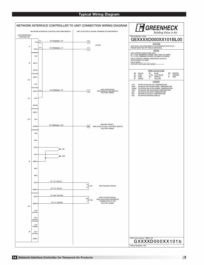
CAUTION UNIT SHALL BE GROUNDED IN ACCORDANCE WITH N.E.C.POWER MUST BE OFF WHILE SERVICING.
NOTESUSE COPPER CONDUTORS ONLY60° C FOR TERMINALS RATED LESS THAN 100 AMPS.75° C FOR TERMINALS RATED 100 AMPS OR MORE.
FIELD CONTROL WIRING RESISTANCE SHOULDNOT EXCEED 0.75 OHM.FIELD WIREDFACTORY SUPPLIED AND WIRED
LEGEND
GEXXXXD000XX101BL00
WIRE COLOR CODE
Wiring Diagram Code:
BK BLACK BL BLUE BR BROWNGY GRAY LT BL LIGHT BLUE O ORANGEPK PINK PR PURPLE R REDW WHITE Y YELLOW
Wiring Template: L00
GND
Y4
GND
ID2
J13
B5
B6
ID1
B2
B3
B4
J2
B1
GND
CONTROLLERpCO5 INTERFACE
J12
NO4
NO3
J1
C3
BLUE
G
GO
J3
NO6
NO5
C5
GND
Y1
Y2J9
Y3
OAI
OAD
NO2
C2
J11
NC1
NO1
C1
(PWM)
J10
DDC Code: Verison - BMS 1.00
TO TERMINAL "R"R
(0/10V)
(0/10V)
(0/10V)
UNIT ELECTRICAL BOARD TERMINALS/COMPONENTSNETWORK INTERFACE CONTROLLER/COMPONENTS
NETWORK INTERFACE CONTROLLER TO UNIT CONNECTION WIRING DIAGRAM
G
PINK TO TERMINAL "G"G
1
REPLACES S1 FAN SWITCHFACTORY WIRED
UNIT START/STOP
XXXX 00 0 XX 0 b
ACC AFTER COOLING COIL TEMPERATUREEAW EXHAUST AIR AFTER WHEEL TEMPERATUREOAAW OUTDOOR AIR AFTER WHEEL TEMPERATUREOAD OUTDOOR AIR DISCHARGE TEMPERATUREOAI OUTDOOR AIR INLET TEMPERATURERAI RETURN AIR INTLET TEMPERATURER20 ROTATION INTERFACE RELAY
TO TERMINAL "C"C
WHITE
24 VAC
®
TO "13" ON ST1
13ST1
TO "14" ON ST114
FAN PROVING STATUS
TO "NO" ON PS2
TO "C" ON PS2
NOPS2
C
D
REPLACES FIELD INTERFACECONNECTION TO PS2
DIRTY FILTER STATUS
FACTORY WIRED
TO TERMINAL "W1"W1
1
REPLACES S4 CALL FOR HEAT SWITCHFACTORY WIRED
HEATING STAGE 1
Typical Wiring Diagram
®
15Network Interface Controller for Tempered Air Products
Display is hard to read. Unit Controller Display: Hold Prg Esc or ! ESC and
Prg Esc
ENTER at the same time, while pressing
Prg Esc
DOWN or
Prg Esc
UP to adjust display contrast.
Remote Display: Hold Prg Esc
or ! ALARM, Prg Esc or ! PRG, and Prg Esc or ! ESC at the same time, while pressing
Prg Esc
DOWN or
Prg Esc
UP to adjust display contrast.
Remote display panel displays “NO LINK” or is blank.
Hold
Prg Esc
DOWN,
Prg Esc
UP and
Prg Esc
ENTER for 4 seconds. Set the display address to 32. The display requires a standard 24 AWG six conductor phone cable connected to the unit controller.
Red alarm button is flashing.
Press the Prg Esc or ! ALARM button to review and clear unit alarms. Enter the DATA LOGGER menu to view previous alarms.
Controller resets itself or is not on.
Check the supply voltage to the controller at terminals G-G0. The board requires 24VAC. Check the 24VAC transformer in the unit control center.
Menus are locked with a password.
The factory default Manufacturer Password = 1000. The factory default Service Password = 1000.
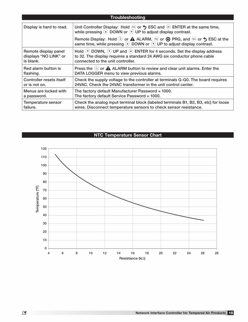
Temperature sensor failure.
Check the analog input terminal block (labeled terminals B1, B2, B3, etc) for loose wires. Disconnect temperature sensors to check sensor resistance.
Troubleshooting
NTC Temperature Sensor Chart
120
110
100
90
80
70
60
50
40
30
20
10
0
4 6 8 10 12 14 16 18 20 22 24 26 28
Tem
per
atur
e (º
F)
Resistance (kΩ)
®
16 Network Interface Controller for Tempered Air Products
To view the current parameters, go the BMS Config menu within the controller by pressing the Prg Esc or ! key.
To access the BMS Config sub-menu, enter the service-password (Default=1000).
Protocol must be BACnet MSTP and BACnet Plugin must be YES.
Press the
Prg Esc
button arrow to view next screen.
Current BACnet MSTP parameters should be displayed. If values appear to be zero, follow the procedure below.
To read current settings:1. Power on controller
and allow several minutes to initialize.
2. Go to BMS Config menu and view BACnet Read/Write screen.
3. Change Function to Read and Update? to YES.
Current BACnet MSTP parameters should now be displayed in the BACnet MSTP SETUP screen. If all values appear to be zeros, consult the factory. (Make sure you have allowed several minutes for the controller to initialize). *Values may appear to be zero prior to setting the Function to READ.
To change BACnet MSTP parameters:
1. Power on the controller and allow several minutes to initialize.
2. Go to BMS Config menu and view MSTP SETUP screen.
3. Move cursor to desired parameter by pressing the Prg Esc
Prg Esc
buttons. Press
Prg Esc
to select the parameter to change. Press the
Prg Esc
Prg Esc
buttons to adjust the parameter. Press
Prg Esc
to save adjusted value.
Parameter Factory Minimum MaximumDevice Instance 77000 0 4194303
Station Address 0 0 127
Max Master 127 0 127
Max Info Frames 20 0 255
Baudrate 38400 9600-19200-38400-76800
4. Once desired parameters have been entered, go to BACnet Read/Write screen. Change Function to Write and Update? to YES.
5. Reboot the controller by cycling power to the unit. Allow several minutes for the controller to initialize.
6. View MSTP parameters. If changed values did not save, contact the factory.
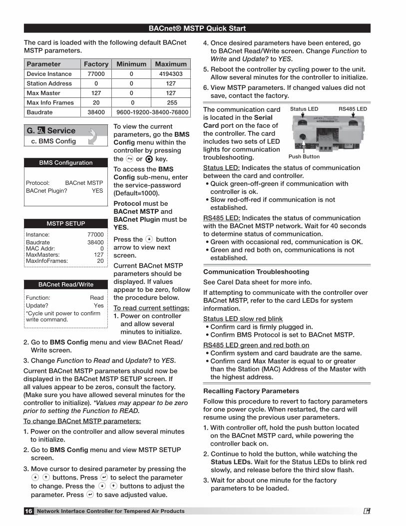
The communication card is located in the Serial Card port on the face of the controller. The card includes two sets of LED lights for communication troubleshooting.
Status LED: Indicates the status of communication between the card and controller.•Quickgreen-off-greenifcommunicationwith
controller is ok.•Slowred-off-redifcommunicationisnot
established.
RS485 LED: Indicates the status of communication with the BACnet MSTP network. Wait for 40 seconds to determine status of communication.•Greenwithoccasionalred,communicationisOK.•Greenandredbothon,communicationsisnot
established.
Communication Troubleshooting
See Carel Data sheet for more info.
If attempting to communicate with the controller over BACnet MSTP, refer to the card LEDs for system information.
Status LED slow red blink•Confirmcardisfirmlypluggedin.•ConfirmBMSProtocolissettoBACnetMSTP.
RS485 LED green and red both on•Confirmsystemandcardbaudratearethesame.•ConfirmcardMaxMasterisequaltoorgreater
than the Station (MAC) Address of the Master with the highest address.
Recalling Factory Parameters
Follow this procedure to revert to factory parameters for one power cycle. When restarted, the card will resume using the previous user parameters.
1. With controller off, hold the push button located on the BACnet MSTP card, while powering the controller back on.
2. Continue to hold the button, while watching the Status LEDs. Wait for the Status LEDs to blink red slowly, and release before the third slow flash.
3. Wait for about one minute for the factory parameters to be loaded.
The card is loaded with the following default BACnet MSTP parameters.
BACnet® MSTP Quick Start
BMS Configuration
Protocol: BACnet MSTPBACnet Plugin? YES
MSTP SETUP
Instance: 77000Baudrate 38400 MAC Addr: 0 MaxMasters: 127 MaxInfoFrames: 20
BACnet Read/Write
Function: ReadUpdate? Yes*Cycle unit power to confirm write command.
G. Servicec. BMS Config
Push Button
Status LED RS485 LED
®

17Network Interface Controller for Tempered Air Products
*The BACnet IP/Eth card is configured for DHCP from the factory.
To view the current parameters, go the BMS Config menu within the controller by pressing the Prg Esc or !
key.
To access the BMS Config sub-menu, enter the service password (Default=1000).
Protocol must be BACnet IP/Eth and BACnet Plugin must be YES.
Press
Prg Esc
arrow button to view next screen.
Current BACnet IP parameters should be displayed. If values appear to be zero, follow the procedure below.
To read current parameters:
1. Power on controller and allow several minutes to initialize.
2. Go to BMS Config menu and view BACnet Read/Write screen.
3. Change Function to Read and Update? to YES.
Current BACnet IP parameters should now be displayed in the BACnet TCP/IP SETUP screen. If all values appear to be zeros, consult the factory. (Make sure you have allowed several minutes for the controller to initialize). *Values may appear to be zero prior to setting the Function to READ.
To change BACnet TCP/IP parameters: 1. Power on the controller and allow several
minutes to initialize. 2. Go to BMS Config menu and view TCP/IP
SETUP screen. 3. Move cursor to desired parameter by pressing
the
Prg Esc
Prg Esc
buttons. Press
Prg Esc
to select the parameter to change. Press the
Prg Esc
Prg Esc
buttons to adjust the parameter. Press
Prg Esc
to save adjusted value.
4. Once desired parameters have been entered, go to BACnet Read/Write screen. Change Function to Write and Update? to YES.
5. Reboot the controller by cycling power to the unit. Allow several minutes for the controller to initialize.
BACnet® IP/Eth Quick Start
BMS Configuration
Protocol: BACnet IP/EthBACnet Plugin? YES
TCP/IP SETUP
Instance: 77000IP set by: DHCP IP: 128.1.104.134 Subnet: 255.255.000.000 Gatewy: 128.1.0.12
TCP/IP Setup
DNS 1: 193.168.001.001DNS 2: 193.168.001.001Type: IP
BACnet Read/Write
Function: ReadUpdate? Yes*Cycle unit power to confirm write command.
G. Servicec. BMS Config
The communication card is located in the Serial Card port on the face of the controller. The card includes two sets of LED lights for communication troubleshooting.
Status LED: Indicates the status of communication between the card and controller.•Quickgreen-off-greenifcommunicationwith
controller is ok.•Slowred-off-redifcommunicationisnot
established.
Ethernet LED: Indicates the status of communication with the network. Wait for 40 seconds to determine status of communication.•Flashinggreen,communicationisOK.•Steadyred,communicationsisnotestablished.
Communication Troubleshooting
See Carel Data sheet for more info.
If attempting to communicate with the controller over BACnet IP/Eth, refer to the card LEDs for system information.
Status LED slow red blink•Confirmcardisfirmlypluggedin.•ConfirmBMSProtocolissettoBACnetIP/Eth.
Ethernet LED red on•Confirmcardisconnectedtothenetwork.
Recalling Factory Parameters
Follow this procedure to revert to factory parameters for one power cycle. When restarted, the card will resume using the previous user parameters.
Factory Default IP address: 172.016.000.001
1. With controller off, hold the push button located on the BACnet IP/Eth card, while powering the controller back on.
2. Continue to hold the button, while watching the Status LED. Wait for the Status LED to blink red slowly, and release before the third slow flash.
3. Wait for about one minute for the factory parameters to be loaded.
4. Follow the procedure to read the current parameters to confirm factory defaults have been loaded.
Push Button
Ethernet LED
Status LED
MAC address
6. View TCP/IP parameters. If changed values did not save, contact the factory.
®

18 Network Interface Controller for Tempered Air Products
Maintenance Log
Date __________________ Time _____________ AM/PM
Notes:___________________________________________
_________________________________________________
_________________________________________________
_________________________________________________
_________________________________________________
Date __________________ Time _____________ AM/PM
Notes:___________________________________________
_________________________________________________
_________________________________________________
_________________________________________________
_________________________________________________
Date __________________ Time _____________ AM/PM
Notes:___________________________________________
_________________________________________________
_________________________________________________
_________________________________________________
_________________________________________________
Date __________________ Time _____________ AM/PM
Notes:___________________________________________
_________________________________________________
_________________________________________________
_________________________________________________
_________________________________________________
Date __________________ Time _____________ AM/PM
Notes:___________________________________________
_________________________________________________
_________________________________________________
_________________________________________________
_________________________________________________
Date __________________ Time _____________ AM/PM
Notes:___________________________________________
_________________________________________________
_________________________________________________
_________________________________________________
_________________________________________________
Date __________________ Time _____________ AM/PM
Notes:___________________________________________
_________________________________________________
_________________________________________________
_________________________________________________
_________________________________________________
Date __________________ Time _____________ AM/PM
Notes:___________________________________________
_________________________________________________
_________________________________________________
_________________________________________________
_________________________________________________
Date __________________ Time _____________ AM/PM
Notes:___________________________________________
_________________________________________________
_________________________________________________
_________________________________________________
_________________________________________________
Date __________________ Time _____________ AM/PM
Notes:___________________________________________
_________________________________________________
_________________________________________________
_________________________________________________
_________________________________________________
Date __________________ Time _____________ AM/PM
Notes:___________________________________________
_________________________________________________
_________________________________________________
_________________________________________________
_________________________________________________
Date __________________ Time _____________ AM/PM
Notes:___________________________________________
_________________________________________________
_________________________________________________
_________________________________________________
_________________________________________________
®

19Network Interface Controller for Tempered Air Products
Maintenance Log
Date __________________ Time _____________ AM/PM
Notes:___________________________________________
_________________________________________________
_________________________________________________
_________________________________________________
_________________________________________________
Date __________________ Time _____________ AM/PM
Notes:___________________________________________
_________________________________________________
_________________________________________________
_________________________________________________
_________________________________________________
Date __________________ Time _____________ AM/PM
Notes:___________________________________________
_________________________________________________
_________________________________________________
_________________________________________________
_________________________________________________
Date __________________ Time _____________ AM/PM
Notes:___________________________________________
_________________________________________________
_________________________________________________
_________________________________________________
_________________________________________________
Date __________________ Time _____________ AM/PM
Notes:___________________________________________
_________________________________________________
_________________________________________________
_________________________________________________
_________________________________________________
Date __________________ Time _____________ AM/PM
Notes:___________________________________________
_________________________________________________
_________________________________________________
_________________________________________________
_________________________________________________
Date __________________ Time _____________ AM/PM
Notes:___________________________________________
_________________________________________________
_________________________________________________
_________________________________________________
_________________________________________________
Date __________________ Time _____________ AM/PM
Notes:___________________________________________
_________________________________________________
_________________________________________________
_________________________________________________
_________________________________________________
Date __________________ Time _____________ AM/PM
Notes:___________________________________________
_________________________________________________
_________________________________________________
_________________________________________________
_________________________________________________
Date __________________ Time _____________ AM/PM
Notes:___________________________________________
_________________________________________________
_________________________________________________
_________________________________________________
_________________________________________________
Date __________________ Time _____________ AM/PM
Notes:___________________________________________
_________________________________________________
_________________________________________________
_________________________________________________
_________________________________________________
Date __________________ Time _____________ AM/PM
Notes:___________________________________________
_________________________________________________
_________________________________________________
_________________________________________________
_________________________________________________
®

20 475262 • Network Interface Controller, Rev. 1, January 2012 Copyright 2012 © Greenheck Fan Corporation
Greenheck warrants this equipment to be free from defects in material and workmanship for a period of one year from the shipment date. Any units or parts which prove to be defective during the warranty period will be replaced at our option when returned to our factory, transportation prepaid. Motors are warranted by the motor manufacturer for a period of one year. Should motors furnished by Greenheck prove defective during this period, they should be returned to the nearest authorized motor service station. Greenheck will not be responsible for any removal or installation costs.
As a result of our commitment to continuous improvement, Greenheck reserves the right to change specifications without notice.
®
Phone:(715)359-6171•Fax:(715)355-2399•E-mail:[email protected]•Website: www.greenheck.com
Warranty
AMCA Publication 410-96, Safety Practices for Users and Installers of Industrial and Commercial Fans, provides additional safety information. This publication can be obtained from AMCA International, Inc. at www.amca.org.