Reference Guide for a 2-Axis Robot Arm with 2-Phase ...
64
R01AN5644EJ0100 Rev.1.00 Page 1 of 62 Jan 22, 2021 Reference Guide for a 2-Axis Robot Arm with 2-Phase Stepping Motors Incorporating Resolvers RX24T, RX72M, RAA3064002GFP/RAA3064003GFP Overview We have developed a reference kit for a 2-axis robot arm with our solution for positional control involving the use of 2-phase stepping motors incorporating resolvers. An RX72M handles the numerical control and two RX24Ts handle motor control of the axes. The system enables movement of the arm at speeds of up to 250 mm per second within the movable range of 150 mm x 153 mm. Features • Trajectory control of the arm (CP control) Continuous path (CP) control by linear or circular interpolation enables consecutive operations along the path as required (a demonstration video is available on the Renesas website). Arm swing speed is adjustable from low to high (0.017 to 5 r/sec) Motor control for axes: The RX24Ts control the motor positions by using the resolver feedback signals (servo control). System control: The RX72M controls the robot arm as a whole, with each of the segments controlled by an RX24T. • High positional resolution of 200,000 P/R A positional resolution of 200,000 pulses per revolution is achieved by using 2-phase stepping motors incorporating resolvers manufactured by MinebeaMitsumi Inc. and resolver-to-digital converters (RDC ICs) manufactured by Renesas Electronics. Repeatable positional accuracy: 0.2 mm The positional resolution is 250 times that achievable by open-loop control • Reducing the reference kit’s size by integrating the mechanical and electrical structures Integral structures with the control boards installed at the opposite ends of the stepping motors from the driving ends of the motor axes. Only requiring the power supply and communications lines reduces the amount and complexity of wiring. • Gearless direct drives Direct drives with high positional resolution eliminate being out-of-step with the resolver positional information and maximize the motor torque. The RX24Ts apply filtering to suppress the mechanical resonances caused by the direct drives. The gearless structure reduces system costs. • High-speed serial communications Modbus communications at 2 Mbps with the use of half-duplex RS485 Applications • Service robots • Small arm robots • Power-assistance robots • XY-stage driving • Automatic guided vehicles • Electrically driven slides • Surveillance camera positioning • Machine tool control • Textile-related machinery • Medical equipment • OA equipment RX72M USB Ethernet ◆Communications Modbus communications at 1 Mbps with the use of half-duplex RS485 Arm 1 Arm 2 RX24T RX24T ◆NC board ・Trajectory control Interpolation calculation (linear interpolation or circular interpolation) Acceleration or deceleration calculation (moving average filter) Joint angle calculation (successive Jacobian calculations) Monoaxial movement (no interpolation or angle specification) ・ Consecutive operations (combinations of motion in straight lines and along arcs) RX24T RX24T RX72M ◆Motor in use ・2-phase stepping motor ◆Resolver ・Position resolution of 200,000 P/R ◆Motor control ・Vector control of position, speed, and current ◆GUI(PC) ・Training ・Running the demo system
Transcript of Reference Guide for a 2-Axis Robot Arm with 2-Phase ...

R01AN5644EJ0100 Rev.1.00 Page 1 of 62 Jan 22, 2021
Reference Guide for a 2-Axis Robot Arm with 2-Phase Stepping Motors Incorporating Resolvers RX24T, RX72M, RAA3064002GFP/RAA3064003GFP
Overview We have developed a reference kit for a 2-axis robot arm with our solution for positional control involving the use of 2-phase stepping motors incorporating resolvers. An RX72M handles the numerical control and two RX24Ts handle motor control of the axes. The system enables movement of the arm at speeds of up to 250 mm per second within the movable range of 150 mm x 153 mm.
Features • Trajectory control of the arm (CP control)
Continuous path (CP) control by linear or circular interpolation enables consecutive operations along the path as required (a demonstration video is available on the Renesas website).
Arm swing speed is adjustable from low to high (0.017 to 5 r/sec)
Motor control for axes: The RX24Ts control the motor positions by using the resolver feedback signals (servo control).
System control: The RX72M controls the robot arm as a whole, with each of the segments controlled by an RX24T.
• High positional resolution of 200,000 P/R A positional resolution of 200,000 pulses per
revolution is achieved by using 2-phase stepping motors incorporating resolvers manufactured by MinebeaMitsumi Inc. and resolver-to-digital converters (RDC ICs) manufactured by Renesas Electronics.
Repeatable positional accuracy: 0.2 mm The positional resolution is 250 times that
achievable by open-loop control • Reducing the reference kit’s size by integrating the
mechanical and electrical structures Integral structures with the control boards installed
at the opposite ends of the stepping motors from the driving ends of the motor axes.
Only requiring the power supply and communications lines reduces the amount and complexity of wiring.
• Gearless direct drives Direct drives with high positional resolution
eliminate being out-of-step with the resolver positional information and maximize the motor torque.
The RX24Ts apply filtering to suppress the mechanical resonances caused by the direct drives.
The gearless structure reduces system costs. • High-speed serial communications
Modbus communications at 2 Mbps with the use of half-duplex RS485
Applications • Service robots • Small arm robots • Power-assistance robots • XY-stage driving • Automatic guided vehicles • Electrically driven slides • Surveillance camera positioning • Machine tool control • Textile-related machinery • Medical equipment • OA equipment
RX72M
USBEthernet
CommunicationsModbus communications at 1 Mbps with the use of half-duplex RS485
Arm 1 Arm 2
RX24T RX24T
NC board・Trajectory control
Interpolation calculation (linear interpolation or circular interpolation)Acceleration or deceleration calculation (moving average filter) Joint angle calculation (successive Jacobian calculations)Monoaxial movement (no interpolation or angle specification)
・ Consecutive operations (combinations of motion in straight lines and along arcs)
RX24T RX24T
RX72M
Motor in use・2-phase stepping motor
Resolver・Position resolution of 200,000 P/R
Motor control・Vector control of position, speed, and current
GUI(PC)・Training・Running the
demo system
R01AN5644EJ0100 Rev.1.00 Page 2 of 62 Jan 22, 2021
Reference Guide for a 2-Axis Robot Arm with 2-Phase Stepping Motors Incorporating Resolvers
RX24T, RX72M, RAA3064002GFP/RAA3064003GFP
Introduction This document is a reference guide for a 2-axis robot arm with 2-phase stepping motors, each incorporating a resolver sensor. The user has to prepare the components of the demo system described in this document. Note that the control board drawings, mechanical part drawings, software for control (for motor control or system control), and a GUI for controlling the demo system, which are listed in Related Documents below, are available for use and can be found on the Renesas Electronics Website.
The demo system can be used for training in movements of the arm tip (written in specific commands) with the use of a GUI on a PC and for moving the arm according to training in continuous path (CP) control by linear or circular interpolation. Refer to the examples of operation posted on the Renesas Electronics Website (URL: https://www.renesas.com/us/en/application/home-building/motor-control-solutions/resolver-motor-control-solutions-consumer-and-industrial-applications#videos).
This document explains the system configuration and mechanical parts of the demo system, circuit diagrams of motor control boards, and methods of manipulating the demo system by using the GUI. For the software to be written to the motor control boards and its control functions, refer to the application note "R01AN5662EJ0100".
Related Documents • Related to mechanical parts
Structural drawings of robot arms: R12TU0118 • Related to control boards
(a) 42-mm square motor control board • Circuit drawings: R12TU0106 • Parts list: R12TU0107 • PCB pattern drawings: R12TU0108
(b) 85-mm square motor control board • Circuit drawings: R12TU0109 • Parts list: R12TU0110 • PCB pattern drawings: R12TU0111
(c) System control board for NC control (Renesas Starter Kit+ for RX72M (part number: RTK5572MNDS10000BE) • User's manual : R20UT4391
(d) Resolver-to-digital converter • User's manual : R03UZ0002
• Related to software
(a) Software for motor control • Application note: R01AN5662EJ0100
(b) Motor control development support tool "Renesas Motor Workbench" • User's manual : R21UZ0004
Related MCUs • RX24T • RX72M

R01AN5644EJ0100 Rev.1.00 Page 3 of 62 Jan 22, 2021
Reference Guide for a 2-Axis Robot Arm with 2-Phase Stepping Motors Incorporating Resolvers
RX24T, RX72M, RAA3064002GFP/RAA3064003GFP
List of Abbreviations and Acronyms Acronym/Abbreviation Formal Name Remarks MCU Microcontroller Demo system A 2-axis robot arm using 2-phase
stepping motors with resolvers Not for sale
42-mm square motor 42-mm square 2-phase stepping motor with a resolver
Manufactured by MinebeaMitsumi Inc. Contact MinebeaMitsumi for detailed specifications.
85-mm square motor 85-mm square 2-phase stepping motor with a resolver
Manufactured by MinebeaMitsumi Inc. Contact MinebeaMitsumi for detailed specifications.
42-mm square board 42-mm square motor control board. An RX24T is incorporated as the MCU.
Not for sale
85-mm square board 85-mm square motor control board. An RX24T is incorporated as the MCU.
Not for sale
NC board System control board for numerical control
NC: Numerical Control The Renesas Starter Kit + for RX72M (part number: RTK5572MNDS10000BE) is used in this demo system.
RMW Motor control development support tool "Renesas Motor Workbench"
Manufactured by Renesas Electronics Corp.
RDC Resolver-to-digital converter IC A resolver-to-digital converter IC (part number: RAA3064002GFP) manufactured by Renesas Electronics Corp. is used on the 42-mm square and 85-mm square boards.
GUI Graphical user interface The demo system uses "Demo_Ver1.1", which is a GUI for the 2-axis robot arm.

R01AN5644EJ0100 Rev.1.00 Page 4 of 62 Jan 22, 2021
Reference Guide for a 2-Axis Robot Arm with 2-Phase Stepping Motors Incorporating Resolvers
RX24T, RX72M, RAA3064002GFP/RAA3064003GFP
Contents
1. Specifications of the Demo System ......................................................................................... 6 1.1 Overall Configuration of the Demo System ............................................................................................. 6 1.2 Motor Control Board .............................................................................................................................. 10 1.2.1 Hardware Specifications ...................................................................................................................... 10 1.2.2 Software Specifications ....................................................................................................................... 19 1.3 NC Board ............................................................................................................................................... 20 1.4 Stepping Motors .................................................................................................................................... 21 1.5 Mechanical Parts ................................................................................................................................... 23 1.6 GUI ........................................................................................................................................................ 26 1.7 Assembly and Wiring ............................................................................................................................. 27
2. Specifications of NC Software ............................................................................................... 31 2.1 Overview ................................................................................................................................................ 31 2.1.1 Applicable Conditions and Functions .................................................................................................. 31 2.2 Definition of the Control Coordinate System ......................................................................................... 32 2.3 Basic Manipulation ................................................................................................................................ 33 2.3.1 Procedure for Operations .................................................................................................................... 33 2.3.2 List of Commands and APIs ................................................................................................................ 34 2.3.3 Output Format of output_state ............................................................................................................ 35 2.3.4 List of Parameters ............................................................................................................................... 36 2.3.5 Error Processing .................................................................................................................................. 37 2.4 Implementation Method ......................................................................................................................... 40 2.4.1 Calculations for Interpolation ............................................................................................................... 40 2.4.2 Acceleration or Deceleration Calculation ............................................................................................ 43 2.4.3 Joint Angle Calculation ........................................................................................................................ 45 2.4.4 Error Correction ................................................................................................................................... 47 2.5 Time Charts ........................................................................................................................................... 48 2.6 List of Used Peripheral Functions and Pins .......................................................................................... 49 2.6.1 SCI6 and SCI10................................................................................................................................... 50 2.6.2 CRC ..................................................................................................................................................... 51 2.7 Project Configuration ............................................................................................................................. 52 2.7.1 Operating Conditions ........................................................................................................................... 52 2.7.2 Configuration Image ............................................................................................................................ 52
3. Operating the Demo System .................................................................................................. 53 3.1 Tuning .................................................................................................................................................... 53 3.1.1 Adjusting the Offset ............................................................................................................................. 53 3.1.2 Adjusting the Resonance Suppressing Filters .................................................................................... 54 3.2 Demonstrations by GUI ......................................................................................................................... 57 3.2.1 Preparations ........................................................................................................................................ 57

R01AN5644EJ0100 Rev.1.00 Page 5 of 62 Jan 22, 2021
Reference Guide for a 2-Axis Robot Arm with 2-Phase Stepping Motors Incorporating Resolvers
RX24T, RX72M, RAA3064002GFP/RAA3064003GFP
3.2.2 Registration of Work Origin ................................................................................................................. 57 3.2.3 Training ................................................................................................................................................ 58 3.2.4 Demonstrations ................................................................................................................................... 60 3.3 Usage Notes .......................................................................................................................................... 61
Revision History ............................................................................................................................ 62

R01AN5644EJ0100 Rev.1.00 Page 6 of 62 Jan 22, 2021
Reference Guide for a 2-Axis Robot Arm with 2-Phase Stepping Motors Incorporating Resolvers
RX24T, RX72M, RAA3064002GFP/RAA3064003GFP
1. Specifications of the Demo System This section describes the overall configuration of the demo system and the specifications of each of the modules.
1.1 Overall Configuration of the Demo System Figure 1-1 shows the external appearance of the demo system, Figure 1-2 is a system configuration diagram, and Figure 1-3 shows a schematic view of controlling the demo system. Table 1-1 lists the components of the demo system.
The 85-mm square motor is housed in a cylindrical case and connected to arm 1, and the 42-mm square motor and arm 2, which operates in accordance with the rotation of the 42-mm square motor, are connected to the tip of arm 1. A laser module is attached to the tip of arm 2 and the laser light produces illumination in the direction of the ground. The 42-mm square board and 85-mm square board are installed for the 42-mm square motor and 85-mm square motor in respective integral structures, and each of the motors rotates to operate the arms upon receiving control instructions from the NC board, which is connected to the control boards via RS-485 links. Origin sensors for detecting the origin positions of arm 1 and arm 2 are attached to arm 1 and the cylindrical case, and the signals from the origin sensors are connected to the 42-mm square board and 85-mm square board. The system control board is connected to a PC by a USB cable, and control instructions for the motors are generated from operation commands generated with a GUI on the PC. The 42-mm square board and 85-mm square board are driven by a 24-V power supply and the NC board is driven by a 5-V power supply. A 3-V power supply generated on the NC board is supplied to the laser module.
Figure 1-1 External Appearance of the Demo System

R01AN5644EJ0100 Rev.1.00 Page 7 of 62 Jan 22, 2021
Reference Guide for a 2-Axis Robot Arm with 2-Phase Stepping Motors Incorporating Resolvers
RX24T, RX72M, RAA3064002GFP/RAA3064003GFP
Figure 1-2 System Configuration Diagram
Figure 1-3 Schematic View of Controlling the Demo System
Arm 1Arm 2
42-mm square stepping motor with a resolver
85-mm square motor control board
85-mm square stepping motor with a resolver(installed inside a cylindrical case)
NC board
24-V power supply
5-V power supply
Cylindrical case
Base
PC to manipulate the GUI
通信線:modbusCommunication line: RS485
Communication line: USB
Origin sensor for arm 1
Origin sensor for arm 2
Laser module
Laser
3-V power supply for the laser module
42-mm square motor control board
RX72M
USBEthernet
CommunicationsModbus communications at 2 Mbps with the use of half-duplex RS485
Arm 1 Arm 2
RX24T RX24T
NC board・Trajectory control
Interpolation calculation (linear interpolation or circular interpolation)Acceleration or deceleration calculation (moving average filter) Joint angle calculation (successive Jacobian calculations)Monoaxial movement (no interpolation or angle specification)
・ Consecutive operations (combinations of motion in straight lines and along arcs)
RX24T RX24T
RX72M
Motor in use・2-phase stepping motor
Resolver・Position resolution of 200,000 P/R
Motor control・Vector control of position, speed, and current
GUI(PC)・Training・Running the
demo system

R01AN5644EJ0100 Rev.1.00 Page 8 of 62 Jan 22, 2021
Reference Guide for a 2-Axis Robot Arm with 2-Phase Stepping Motors Incorporating Resolvers
RX24T, RX72M, RAA3064002GFP/RAA3064003GFP
Table 1-1 List of Components of the Demo System (1/2)
Classification Name Description Related Files Motor control board
42-mm square motor control board
Control board for driving the 42-mm square stepping motor. It is installed at the opposite end of the 42-mm square stepping motor from the driving end of the motor axis. An RX24T and RDC IC are mounted on this control board.
Circuit drawings: R12TU0106 Parts list: R12TU0107 PCB pattern drawings: R12TU0108 Software: RX24T_ROBOT42_STM_RSL V_FOC
85-mm square motor control board
Control board for driving the 85-mm square stepping motor. It is installed at the opposite end of the 85-mm square stepping motor from the driving end of the motor axis. An RX24T and RDC IC are mounted on this control board.
Circuit drawings: R12TU0109 Parts list: R12TU0110 PCB pattern drawings: R12TU0111 Software: RX24T_ROBOT85_STM_RSL V_FOC
Stepping motor 42-mm square stepping motor with a resolver
42-mm square stepping motor with integrated mechanical and electrical structures (manufactured by MinebeaMitsumi). This motor is used for driving arm 2.
For the model number and detailed specifications, contact MinebeaMitsumi. Contact URL: https://www.minebeamitsumi.com/english/
85-mm square stepping motor with a resolver
85-mm square stepping motor with integrated mechanical and electrical structures (manufactured by MinebeaMitsumi). This motor is used for driving arm 1.
For the model number and detailed specifications, contact MinebeaMitsumi. Contact URL: https://www.minebeamitsumi.com/english/
System control board
System control board
Used for performing 2-axis CP control. The starter kit for the Renesas microcontroller RX72M is used.
Renesas Starter Kit + for RX72M [RTK5572MNDS10000BE] https://www.renesas.com/us/en/products/microcontrollers-microprocessors/rx-32-bit-performance-efficiency-mcus/rx72m-starter-kit-plus-renesas-starter-kit-rx72m
Mechanical parts Structural parts for demo system
Structural parts, such as the arms, cylindrical case, base, and origin sensors. The details are given in related files.
Structural drawings: R12TU0118
Power supply 24-V power supply Power supply for the 42-mm square motor control board and 85-mm square motor control board. Use a power supply unit with the output power of at least 24 V DC/2 A.
5-V power supply 5-V DC power supply for the system control board

R01AN5644EJ0100 Rev.1.00 Page 9 of 62 Jan 22, 2021
Reference Guide for a 2-Axis Robot Arm with 2-Phase Stepping Motors Incorporating Resolvers
RX24T, RX72M, RAA3064002GFP/RAA3064003GFP
Table 1-1 List of Components of the Demo System (2/2)
Classification Name Description Related Files PC PC for GUI PC for a GUI used to execute
demonstrations. For operating the GUI, the following requirements have to be met in the PC. Supporting OS: 32-bit or 64-bit version of Windows 7, 8.1, and 10 File: .NET Framework 4.7.2 or later
GUI GUI for training in and operating the demo system
File name: Demo_Ver1.1.exe
R01AN5644EJ0100 Rev.1.00 Page 10 of 62 Jan 22, 2021
Reference Guide for a 2-Axis Robot Arm with 2-Phase Stepping Motors Incorporating Resolvers
RX24T, RX72M, RAA3064002GFP/RAA3064003GFP
1.2 Motor Control Board 1.2.1 Hardware Specifications Table 1-2 shows the system specifications of the motor control boards. The two motor control boards are the 42-mm square board and 85-mm square board for the motors with the corresponding dimensions. An MCU (64-pin RX24T) and RDC IC, both made by Renesas Electronics, are mounted on both of them, and the 2-phase stepping motors with resolvers can be driven in fast decay mode. Though the RDC IC made by Renesas Electronics has a function for correcting errors in the resolver angle, that function is not used on the 42-mm and 85-mm square boards of this demo system.
For detailed circuit diagrams of each board, see R12TU0106 for the 42-mm square board and R12TU0109 for the 85-mm square board.

R01AN5644EJ0100 Rev.1.00 Page 11 of 62 Jan 22, 2021
Reference Guide for a 2-Axis Robot Arm with 2-Phase Stepping Motors Incorporating Resolvers
RX24T, RX72M, RAA3064002GFP/RAA3064003GFP
Table 1-2 System Specifications of Motor Control Board
Item Function 42-mm Square Board 85-mm Square Board Input power supply Motor power supply 24-V DC As at left
Decoupling capacitor 330 uF 400 uF Internally generated power supply
Gate driver power supply
No (generated within a gate driver)
12 V
Logic power supply, analog power supply
5 V As at left
Control microcomputer
MCU part number R5F524TAADFM (64-pin, 256 KB, Ver. A)
As at left
Firmware rewriting The MD/FINED pin is used (single-wire). Note: A 14-pin connector is not mounted.
As at left
Driver Gate driver Gate driver with built-in FET (DRV8844 manufactured by Texas Instruments Inc.)
Pressure resistance: 60 V Rated current: 1.75 A RMS
UCC27282 manufactured by Texas Instruments Inc. (pressure resistance: 120 V) Drive current: 2.5 A
Driver FET SQJB90EP manufactured by Vishay Intertechnology, Inc. (pressure resistance: 80 V) Rated current: 30 A
Interface Communication RMW, pulse string, RS485 As at left Servocontrol No As at left Sensor Resolver (RDC IC is installed,
part number: RAA3064002GFP), origin sensor (DOG, FLS, or RLS)
As at left
Motor control Gate drive system Fast decay As at left Current detection 2-phase source current is
amplified by the RDC's internal amplifier.
As at left
Protection function Overcurrent sensing Detected in the power supply current. When overcurrent is detected, the PWM output is stopped (POE).
As at left
Gate driver Thermal shutdown or overcurrent
No
Hardware reset Pressing the reset switch returns the system to the initial state.
As at left

R01AN5644EJ0100 Rev.1.00 Page 12 of 62 Jan 22, 2021
Reference Guide for a 2-Axis Robot Arm with 2-Phase Stepping Motors Incorporating Resolvers
RX24T, RX72M, RAA3064002GFP/RAA3064003GFP
(1) Functional block diagram of 42-mm square board Figure 1-4 shows a functional block diagram of the 42-mm square board.
Figure 1-4 Functional Block Diagram of 42-mm Square Board (2) External appearance of 42-mm square board Figure 1-5 shows the external appearance of the 42-mm square board.
Figure 1-5 External Appearance of 42-mm Square Board
RDC
RX24T
RDC IC
PreDrv FET
DC/DC LDO(VDD, AVDD)
PRG
RM
W
Res
olve
r
VM/G
ND
A+/A
-/B-
/B-
BPFExcitation
RMWcommunication
board
Conversion board
E2 LitePC Motor
Resolversensor
Over-currentdetector
5 V
42-mm square board
24-V DC power supply
Isense
IiOUT
Excitation, correction, COUT, SPI
Xtal
Driver
RS4
85
AVDDVDD
VMOT
VMOT
AVDDVDD
Gate driver with built-in FET
Sens
or
Conversion board
42-mm square motor
Top Bottom (view from solder side)
34.92
34.9
2

R01AN5644EJ0100 Rev.1.00 Page 13 of 62 Jan 22, 2021
Reference Guide for a 2-Axis Robot Arm with 2-Phase Stepping Motors Incorporating Resolvers
RX24T, RX72M, RAA3064002GFP/RAA3064003GFP
(3) Component layout of 42-mm square board Figure 1-6 shows a component layout diagram of the 42-mm square board. Table 1-3 lists the interface connector specifications of the 42-mm square board.
Figure 1-6 Component Layout Diagram of 42-mm Square Board
Table 1-3 Interface Connector Specifications (42-mm Square Board)
Item Function Pin (in ascending order of pin number from pin 1) Connector Shape
Power source Power input GND, V+ 2.54-mm pitch, 2-pin Motor Motor output A-, A+, B+, B- 2.0-mm pitch, 4-pin Communication Program
(E1 or E2 Lite) GND, RX, TX, +5V, MD/FINED, RES# 1.27-mm pitch, 6-pin
RMW GND, RX, TX, +5V (pins are used in common with the above program)
1.27-mm pitch, 4-pin
RS485 GND, B/Z, A/Y, NC 1.27-mm pitch, 4-pin Sensor Resolver XBN, XBP, XAP, XAN, EXC 1.27-mm pitch, 5-pin
Origin sensor GND, +5V, RLS, FLS, DOG 1.27-mm pitch, 5-pin
Driv
er
Top
MCU
DC/DCLDO
SW
Xtal
Tran.
Bottom (view from solder side)
RDC
Rectifier diode
Shun
t
Shunt+Amp
Shunt
Buffer Buffer
Prog
ram
/RM
W
Origin sensor
Mot
or o
utpu
t
Resolver
RS4
85
Power input

R01AN5644EJ0100 Rev.1.00 Page 14 of 62 Jan 22, 2021
Reference Guide for a 2-Axis Robot Arm with 2-Phase Stepping Motors Incorporating Resolvers
RX24T, RX72M, RAA3064002GFP/RAA3064003GFP
(4) MCU pin assignment of 42-mm square board Table 1-4 shows the MCU pin assignment of the 42-mm square board.
Table 1-4 MCU Pin Assignment (42-mm Square Board) (1/2)
Pin No. Pin Name I/O Function of Connected Signal
Connection Destination
1 MTIOC9D O RDC I/F (CARRIER signal) RDC 5 IRQ4 I MCU_FLS Sensor 12 SSLA1 O RDC I/F (CS# signal) RDC 13 TMO1 O RDC I/F (CLK signal) RDC 14 PD5 O RDC I/F (RESET# signal) RDC 15 PD4 O UART I/F (RE# signal) RS485 16 TMO0 O RDC I/F (PWMINA signal) RDC 17 RXD5 I UART I/F (RX signal) RMW 18 TXD5 O UART I/F (TX signal) RMW 19 IRQ3 I RDC I/F (ALARM# signal) RDC 20 RSPCKA O RDC I/F (SCLK signal) RDC 21 TXD6 O UART I/F (DI signal of RS485 transceiver) RS485 22 RXD6 I UART I/F (RO signal of RS485 transceiver) RS485 24 POE4# I Overcurrent signal Overcurrent
sensing 26 27 MTIOC7A I RDC I/F (COUT signal) RDC 28 P93 O UART I/F (DE signal) RS485 29 P92 O LED LED 30 MTIOC7C O RDC I/F (CC signal) RDC 31 P90 O nRESET Gate driver 33 MTIOC4C O Motor gate drive PWM B+L Gate driver 34 MTIOC3D O Motor gate drive PWM A+L Gate driver 35 P73 O PWM_EN Gate driver 36 MTIOC4A O Motor gate drive PWM B+H Gate driver 37 MTIOC3B O Motor gate drive PWM A+H Gate driver 38 IRQ5 I MCU_CLR Higher-layer
device 40 MTCLKC I MCU_PULSE Higher-layer
device 42 MTCLKD I MCU_DIR Higher-layer
device 43 TMO6 O RDC I/F (PWMINB signal) RDC 44 MOSIA O RDC I/F (SDI signal) RDC 45 MISOA I RDC I/F (SDO signal) RDC 46 MTIOC9A O RDC I/F (CARRIER signal) RDC 49 IRQ2 I nFault Gate driver 50 IRQ1 I MCU_RLS Higher-layer
device 51 IRQ0 I MCU_DOG Sensor 52 AN207 I Power-supply voltage detection Voltage detecting
circuit 53 AN206 I MNTOUT RDC 55

R01AN5644EJ0100 Rev.1.00 Page 15 of 62 Jan 22, 2021
Reference Guide for a 2-Axis Robot Arm with 2-Phase Stepping Motors Incorporating Resolvers
RX24T, RX72M, RAA3064002GFP/RAA3064003GFP
Table 1-4 MCU Pin Assignment (42-mm Square Board) (2/2)
Pin No. Pin Name I/O Function of Connected Signal
Connection Destination
55 AN101 I Motor current detection B RDC 56 AN100 I Motor current detection A RDC
R01AN5644EJ0100 Rev.1.00 Page 16 of 62 Jan 22, 2021
Reference Guide for a 2-Axis Robot Arm with 2-Phase Stepping Motors Incorporating Resolvers
RX24T, RX72M, RAA3064002GFP/RAA3064003GFP
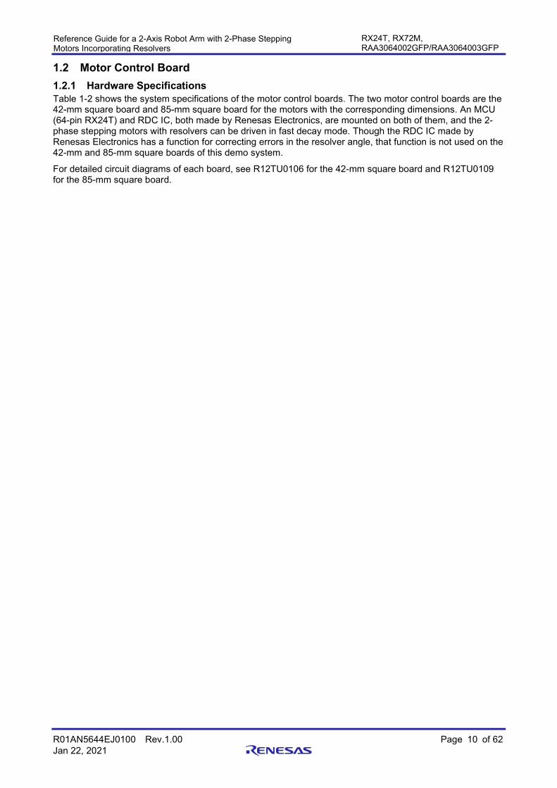
(5) Functional block diagram of 85-mm square board Figure 1-7 shows a functional block diagram of the 85-mm square board.
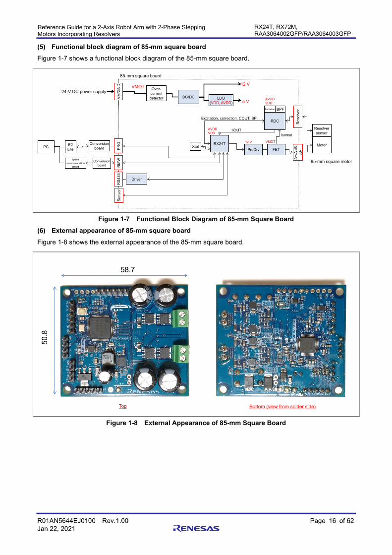
Figure 1-7 Functional Block Diagram of 85-mm Square Board (6) External appearance of 85-mm square board Figure 1-8 shows the external appearance of the 85-mm square board.
Figure 1-8 External Appearance of 85-mm Square Board
85-mm square board
RDC
RX24T
RDC
PreDrv FET
DC/DC LDO(VDD, AVDD)
PRG
RM
W
Res
olve
r
VM/G
ND
A+/A
-/B-
/B-
BPFExcitation
RMW communication
board
E2 LitePC Motor
Resolversensor
Over-currentdetector
5 V
24-V DC power supply
IsenseIiOUT
Excitation, correction, COUT, SPI
Xtal
Driver
RS4
85
AVDDVDD
VMOT
VMOT
AVDDVDD
Sens
or
12 V
12 V
Conversion board
Conversion board
85-mm square motor
Top Bottom (view from solder side)
58.7
50.8

R01AN5644EJ0100 Rev.1.00 Page 17 of 62 Jan 22, 2021
Reference Guide for a 2-Axis Robot Arm with 2-Phase Stepping Motors Incorporating Resolvers
RX24T, RX72M, RAA3064002GFP/RAA3064003GFP
(7) Component layout of 85-mm square board Figure 1-9 shows a component layout diagram of the 85-mm square board. Table 1-5 lists the interface connector specifications of the 85-mm square board.
Figure 1-9 Component Layout Diagram of 85-mm Square Board
Table 1-5 Interface Connector Specifications (85-mm Square Board)
Item Function Pin (in ascending order of pin number from pin 1) Connector Shape
Power source Power input GND, V+ 3.5-mm pitch, 2-pin Motor Motor output A-, A+, B+, B- φ1 mm × 4 Communication Program
(E1 or E2 Lite) GND, RX, TX, +5V, MD/FINED, RES# 2.54-mm pitch, 6-pin
RMW GND, RX, TX, +5V 2.54-mm pitch, 4-pin RS485 GND, B/Z, A/Y, +5V 2.54-mm pitch, 4-pin
Sensor Resolver XBN, XBP, XAP, XAN, EXC 2.54-mm pitch, 5-pin Origin sensor GND, +5V, RLS, FLS, DOG 2.54-mm pitch, 5-pin
Top Bottom (view from solder side)
MCU
DC/DC
LDO
Shun
t
SW
Xtal
Inductor
Shun
t
Driver
RDC
Rectifier diode
BPF
APF
Excitation LPF
Shunt+Amp
Driver
Driver
Driver
Rectifier diode
FET FET
FETFET
Resolver
Prog
ram
RS4
85
Power input
Mot
or o
utpu
t
Origin sensor
RM
W

R01AN5644EJ0100 Rev.1.00 Page 18 of 62 Jan 22, 2021
Reference Guide for a 2-Axis Robot Arm with 2-Phase Stepping Motors Incorporating Resolvers
RX24T, RX72M, RAA3064002GFP/RAA3064003GFP
(8) MCU pin assignment of 85-mm square board Table 1-6 shows the MCU pin assignment of the 85-mm square board.
Table 1-6 MCU Pin Assignment (85-mm Square Board) (1/2)
Pin No. Pin Name I/O Function of Connected Signal
Connection Destination
1 MTIOC9D O RDC I/F (CARRIER signal) RDC 5 IRQ4 I MCU_FLS Sensor 12 SSLA1 O RDC I/F (CS# signal) RDC 13 TMO1 O RDC I/F (CLK signal) RDC 14 PD5 O RDC I/F (RESET# signal) RDC 15 PD4 O UART I/F (RE# signal) RS485 16 TMO0 O RDC I/F (PWMINA signal) RDC 17 RXD5 I UART I/F (RX signal) RMW 18 TXD5 O UART I/F (TX signal) RMW 19 IRQ3 I RDC I/F (ALARM# signal) RDC 20 RSPCKA O RDC I/F (SCLK signal) RDC 21 TXD6 O UART I/F (DI signal of RS485 transceiver) RS485 22 RXD6 I UART I/F (RO signal of RS485 transceiver) RS485 24 POE4# I Overcurrent signal Overcurrent
sensing 26 27 MTIOC7A I RDC I/F (COUT signal) RDC 28 P93 O UART I/F (DE signal) RS485 29 P92 O LED LED 30 MTIOC7C O RDC I/F (CC signal) RDC 31 33 MTIOC4C O Motor gate drive PWM B+L Gate driver 34 MTIOC3D O Motor gate drive PWM A+L Gate driver 35 36 MTIOC4A O Motor gate drive PWM B+H Gate driver 37 MTIOC3B O Motor gate drive PWM A+H Gate driver 38 IRQ5 I MCU_CLR Higher-layer
device 40 MTCLKC I MCU_PULSE Higher-layer
device 42 MTCLKD I MCU_DIR Higher-layer
device 43 TMO6 O RDC I/F (PWMINB signal) RDC 44 MOSIA O RDC I/F (SDI signal) RDC 45 MISOA I RDC I/F (SDO signal) RDC 46 MTIOC9A O RDC I/F (CARRIER signal) RDC 49 50 IRQ1 I MCU_RLS Higher-layer
device 51 IRQ0 I MCU_DOG Sensor 52 AN207 I Power-supply voltage detection Voltage detecting
circuit 53 AN206 I MNTOUT_DC RDC 54 AN102 I MNTOUT_AC RDC

R01AN5644EJ0100 Rev.1.00 Page 19 of 62 Jan 22, 2021
Reference Guide for a 2-Axis Robot Arm with 2-Phase Stepping Motors Incorporating Resolvers
RX24T, RX72M, RAA3064002GFP/RAA3064003GFP
Table 1-6 MCU Pin Assignment (85-mm Square Board) (2/2)
Pin No. Pin Name I/O Function of Connected Signal
Connection Destination
55 AN101 I Motor current detection B RDC 56 AN100 I Motor current detection A RDC
1.2.2 Software Specifications Figure 1-10 shows a functional block diagram of vector control of a 2-phase stepping motor with a resolver used for driving the robot arm, which is used for writing to each of the MCUs (on the 42-mm square board and 85-mm square board) of the demo system. Control of the positions of the motors is based on the resolver feedback signals and position references from the NC board.
For details on algorithms for controlling the motors and the software configuration, refer to the application note "R01AN5662EJ0100".
Figure 1-10 Vector Control of a 2-Phase Stepping Motor with a Resolver
Decoupling control
PWMCurrentPI
Speed PI
dq
αβ
dq
αβ
Resolver
ω* id*
ω
iq*
vd*
θ
idiq
iα
iβ
θ
vα
vβ
+-
++
Position P+ Speed FF
θ*
θ
iq id vd**vq**
Voltagelimit
iq** vq* vq*
Voltageerror
compen-sation
vα
vβ
ω
θSwitch
Position/Speedloop mode
Positionprofiling
θ_reference
IPD controller+ Position P + Speed FF
Switch Position/Speed loop controller
AD Scan End Interrupt Process (50 us)Interrupt Process (250 us)
ω* ω*iq*id*
ω_reference
MA
Aー
BB
Flux-weakening
iq idω
Speedobserver
RDC
Phasedetection
ー
iq_reference
Angle/Speed conv

R01AN5644EJ0100 Rev.1.00 Page 20 of 62 Jan 22, 2021
Reference Guide for a 2-Axis Robot Arm with 2-Phase Stepping Motors Incorporating Resolvers
RX24T, RX72M, RAA3064002GFP/RAA3064003GFP
1.3 NC Board Figure 1-11 shows the external appearance of the NC board. The Renesas Starter Kit + for RX72M (part number: RTK5572MNDS10000BE) is used as the NC board of this demo system and the MCU is RX72M. The PC and NC board are connected via a USB cable, CP control is handled upon receiving operation instructions from a GUI running on the PC, and position references of the motor are sent to the 42-mm square board and 85-mm square board which are connected via RS485. The laser module is connected to PMOD2 and the DC3V power is supplied. Note that DC5V is necessary for the power supply of the NC board.
For details on hardware specifications and the method for writing by software, see Renesas Starter Kit + for RX72M User’s Manual.
Figure 1-11 External Appearance of NC Board
Connected to RX24T (RS485)
Connected to PC (USB)
Connected to power supply (DC5V, 10 W)
Connected to debugger (E1 or E2 Lite)
Connected to laser module (PMOD2)
R01AN5644EJ0100 Rev.1.00 Page 21 of 62 Jan 22, 2021
Reference Guide for a 2-Axis Robot Arm with 2-Phase Stepping Motors Incorporating Resolvers
RX24T, RX72M, RAA3064002GFP/RAA3064003GFP
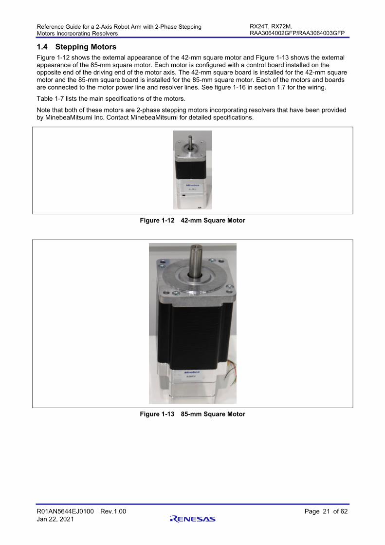
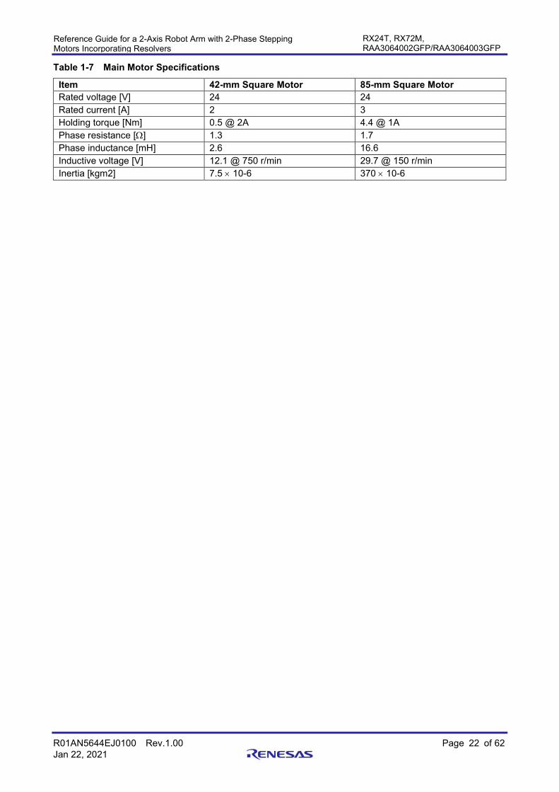
1.4 Stepping Motors Figure 1-12 shows the external appearance of the 42-mm square motor and Figure 1-13 shows the external appearance of the 85-mm square motor. Each motor is configured with a control board installed on the opposite end of the driving end of the motor axis. The 42-mm square board is installed for the 42-mm square motor and the 85-mm square board is installed for the 85-mm square motor. Each of the motors and boards are connected to the motor power line and resolver lines. See figure 1-16 in section 1.7 for the wiring.
Table 1-7 lists the main specifications of the motors.
Note that both of these motors are 2-phase stepping motors incorporating resolvers that have been provided by MinebeaMitsumi Inc. Contact MinebeaMitsumi for detailed specifications.
Figure 1-12 42-mm Square Motor
Figure 1-13 85-mm Square Motor
R01AN5644EJ0100 Rev.1.00 Page 22 of 62 Jan 22, 2021
Reference Guide for a 2-Axis Robot Arm with 2-Phase Stepping Motors Incorporating Resolvers
RX24T, RX72M, RAA3064002GFP/RAA3064003GFP
Table 1-7 Main Motor Specifications
Item 42-mm Square Motor 85-mm Square Motor Rated voltage [V] 24 24 Rated current [A] 2 3 Holding torque [Nm] 0.5 @ 2A 4.4 @ 1A Phase resistance [Ω] 1.3 1.7 Phase inductance [mH] 2.6 16.6 Inductive voltage [V] 12.1 @ 750 r/min 29.7 @ 150 r/min Inertia [kgm2] 7.5 × 10⁻⁶ 370 × 10-6

R01AN5644EJ0100 Rev.1.00 Page 23 of 62 Jan 22, 2021
Reference Guide for a 2-Axis Robot Arm with 2-Phase Stepping Motors Incorporating Resolvers
RX24T, RX72M, RAA3064002GFP/RAA3064003GFP
1.5 Mechanical Parts Table 1-8 lists the component parts of the demo system. For the drawings of mechanical processed products, refer to Structural drawings of robot arms (R12TU0118).
Table 1-8 List of Component Parts of the Demo System (1)
No. Model Number (Figure No.) Product Name Manufacturer
Required Quantity Description
1 RE00MT BASE Mechanical processed product (created based on drawings)
1 Base
2 RE00MV COVER_rev1 Mechanical processed product (created based on drawings)
1 Cylindrical case
3 85-mm square MOTOR ASS'Y
85-mm square mechanically and electrically integrated motor
MinebeaMitsumi 1 Integral structure with an 85-mm square board installed for the 85-mm square motor
4 RE00MU BASE_PLATE Mechanical processed product (created based on drawings)
1 Lid of cylindrical case
5 RE00MR LOAD_SHAFT Mechanical processed product (created based on drawings)
1 Part for installing the 85-mm square motor and arm 1
6 RE00MQ ARM_1 Mechanical processed product (created based on drawings)
1 Arm 1
7 42-mm square MOTOR ASS'Y
42-mm square mechanically and electrically integrated motor
MinebeaMitsumi 1 Integral structure with a 42-mm square board installed for the 42-mm square motor
8 RE00MP LOAD_SHAFT Mechanical processed product (created based on drawings)
1 Part for installing the 42-mm square motor and arm 2
9 RE00MK ARM_2_Rev0 Mechanical processed product (created based on drawings)
1 Arm 2
10 RE00NQ BLOCK Mechanical processed product (created based on drawings)
1 Part for fixing the laser module
11 FU650AD5-C6 Red dot laser module
Akizuki Denshi Tsusho Co., Ltd.
1 Red dot laser module, 1 mW, driven by 3 V
12 RE00LH STOPPER_1 Mechanical processed product (created based on drawings)
2 Part for fixing the stopper for preventing arm rotation

R01AN5644EJ0100 Rev.1.00 Page 24 of 62 Jan 22, 2021
Reference Guide for a 2-Axis Robot Arm with 2-Phase Stepping Motors Incorporating Resolvers
RX24T, RX72M, RAA3064002GFP/RAA3064003GFP
Table 1-8 List of Component Parts of the Demo System (2)
No. Model Number (Figure No.) Product Name Manufacturer
Required Quantity Description
13 SETGRS10-30-SC5
Circular post - one end threaded and one end tapped
MISUMI Group Inc. 4 Stopper for preventing arm rotation
14 RE00NE DOG_1 Mechanical processed product (created based on drawings)
1 Part for detection in the origin sensor for arm 1
15 RE00LM DOG_2 Mechanical processed product (created based on drawings)
1 Part for detection in the origin sensor for arm 2
16 EE_SX772A Photomicrosensor OMRON Corporation
1 Origin sensor for arm 1
17 EE_SX672R Photomicrosensor OMRON Corporation
1 Origin sensor for arm 2
18 HFC5_3060_B Frame cap for aluminum extrusion
MISUMI Group Inc. 2 Frame cap for arm 1
19 HFC5_2040_B Frame cap for aluminum extrusion
MISUMI Group Inc. 2 Frame cap for arm 2
20 SCB6-20 Hex socket head cap screw - stainless steel
MISUMI Group Inc. 4 M6 × 20 mm
21 SCB5-16 Hex socket head cap screw - stainless steel
MISUMI Group Inc. 16 M5 × 16 mm
22 SHNTP6-4 Post-assembly insertion spring nut for 30-mm or 60-mm square aluminum extrusion
MISUMI Group Inc. 4 Part for fixing the stopper for preventing arm rotation
23 SCB4-20 Hex socket head cap screw - stainless steel
MISUMI Group Inc. 4 M4 × 20 mm
24 SCB3-25 Hex socket head cap screw - stainless steel
MISUMI Group Inc. 8 M3 × 25 mm
25 SCB3-20 Hex socket head cap screw - stainless steel
MISUMI Group Inc. 4 M3 × 20 mm
26 SCB3-10 Hex socket head cap screw - stainless steel
MISUMI Group Inc. 3 M3 × 10 mm
27 SCB3-8 Hex socket head cap screw - stainless steel
MISUMI Group Inc. 3 M3 × 8 mm
28 SCB3-6 Hex socket head cap screw - stainless steel
MISUMI Group Inc. 6 M3 × 6 mm
29 SCB3-5 Hex socket head cap screw - stainless steel
MISUMI Group Inc. 4 M3 × 5 mm
R01AN5644EJ0100 Rev.1.00 Page 25 of 62 Jan 22, 2021
Reference Guide for a 2-Axis Robot Arm with 2-Phase Stepping Motors Incorporating Resolvers
RX24T, RX72M, RAA3064002GFP/RAA3064003GFP
Table 1-8 List of Component Parts of the Demo System (3)
No. Model Number (Figure No.) Product Name Manufacturer
Required Quantity Description
30 MSSF3-3 Hex socket set screw - flat end
MISUMI Group Inc. 1 M3 × 3 mm locking screw
31 SHNTU5-3 Pre-assembly insertion spring nut for 20-mm, 25-mm, or 40-mm square aluminum extrusion
MISUMI Group Inc. 2 Part for fixing the laser module
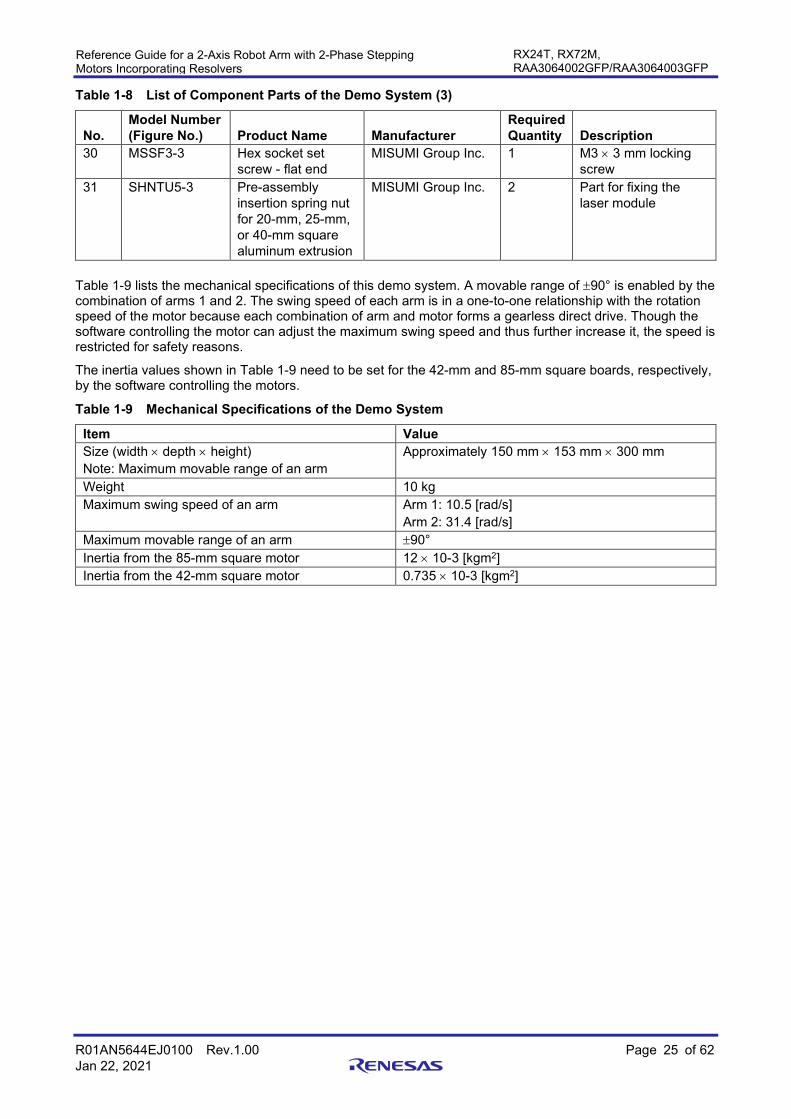
Table 1-9 lists the mechanical specifications of this demo system. A movable range of ±90° is enabled by the combination of arms 1 and 2. The swing speed of each arm is in a one-to-one relationship with the rotation speed of the motor because each combination of arm and motor forms a gearless direct drive. Though the software controlling the motor can adjust the maximum swing speed and thus further increase it, the speed is restricted for safety reasons.
The inertia values shown in Table 1-9 need to be set for the 42-mm and 85-mm square boards, respectively, by the software controlling the motors.
Table 1-9 Mechanical Specifications of the Demo System
Item Value Size (width × depth × height) Note: Maximum movable range of an arm
Approximately 150 mm × 153 mm × 300 mm
Weight 10 kg Maximum swing speed of an arm Arm 1: 10.5 [rad/s]
Arm 2: 31.4 [rad/s] Maximum movable range of an arm ±90° Inertia from the 85-mm square motor 12 × 10-3 [kgm2] Inertia from the 42-mm square motor 0.735 × 10⁻³ [kgm2]

R01AN5644EJ0100 Rev.1.00 Page 26 of 62 Jan 22, 2021
Reference Guide for a 2-Axis Robot Arm with 2-Phase Stepping Motors Incorporating Resolvers
RX24T, RX72M, RAA3064002GFP/RAA3064003GFP
1.6 GUI "Demo_Ver1.1.exe", which is a GUI for this demo system operates on a PC without having to be installed. The necessary conditions for running on a PC are as follows:
Supporting OS: Windows 7 (32-bit or 64-bit version), Windows 8.1 (32-bit or 64-bit version), and Windows
10 (32-bit or 64-bit version) Required file: .NET Framework 4.7.2 or later Store the GUI file in any folder of the PC and double-click on the GUI icon (see Figure 1-14) to start the GUI (see Figure 1-15).
Figure 1-14 GUI Icon
Figure 1-15 Screen after GUI Startup

R01AN5644EJ0100 Rev.1.00 Page 27 of 62 Jan 22, 2021
Reference Guide for a 2-Axis Robot Arm with 2-Phase Stepping Motors Incorporating Resolvers
RX24T, RX72M, RAA3064002GFP/RAA3064003GFP
1.7 Assembly and Wiring Assemble the mechanical parts according to the assembly drawing in Figure No. RE00NR of Structural drawings of robot arms (R12TU0118). The test operations in section 3 have to proceed before assembling the 42-mm and 85-mm square motors.
Figure 1-16 shows an overall view of the electrical wiring and Table 1-10 to Table 1-23 show the specifications for connecting the connectors. Wiring should be in accord with Table 1-10 to Table 1-23. Connect a debugger and the RMW if this is required. When connecting the RMW, a communications board such as the W2002 ICS++ (manufactured by Desk Top Laboratories Inc.) is convenient because it allows connection to a PC via a USB cable. For connecting a debugger and the power supply for the NC board, see Renesas Starter Kit + for RX72M User’s Manual (R20UT4391). Note that since some of the 42-mm square board's connection pins are used in common with the debugger and RMW, the two cannot be connected to this board at the same time.
Figure 1-16 Overall View of Electrical Wiring
Table 1-10 Connection between the 42-mm Square Board and 42-mm Square Motor
42-mm Square Board Motor Output Motor Pin No. Pin Name Name Meaning 1 A− A− A phase − 2 A+ A+ A phase + 3 B+ B+ B phase + 4 B− B− B phase −
Table 1-11 Connection between the 42-mm Square Board and Resolver
42-mm Square Board Resolver Resolver Pin No. Pin Name Name Meaning 1 XBN 270° phase Cos- 2 XBP 90° phase Cos+ 3 XAP 0° phase Sin+ 4 XAN 180° phase Sin- 5 EXC Excitation Excitation
RMW(PC)
Debugger
Origin sensor
NC board
24-V DCpower supply
42-mm square motor
Resolver
Origin sensor
Mot
orR
esol
ver
RS485 Power supply
Prog
ram
/R
MW
42-mm square board
RS485
Pow
er
supp
lyPM
OD
2
E1/E
2Li
te
Debugger
Laser module
5-V DCpower supply
RMW(PC)
Debugger
Origin sensor
85-mm square motor
Resolver
Origin sensor
Mot
orR
esol
ver
RS485 Power supply
Prog
ram
85-mm square boardR
MW

R01AN5644EJ0100 Rev.1.00 Page 28 of 62 Jan 22, 2021
Reference Guide for a 2-Axis Robot Arm with 2-Phase Stepping Motors Incorporating Resolvers
RX24T, RX72M, RAA3064002GFP/RAA3064003GFP
Table 1-12 Connection between the 42-mm Square Board, Emulator, and PC
42-mm Square Board Program/RMW When Connected to Emulator When Connected to PC (RMW) Pin No. Pin Name Name Meaning Name Meaning 1 GND GND GND GND GND 2 RX (Not used) RX RMW
transmission 3 TX (Not used) TX RMW reception 4 +5V 5V Power supply from emulator 5V 5-V power
supply 5 MD/FINED FINE FINE in emulator (Not used) 6 RES# RESET RES in emulator (Not used)
Table 1-13 Connection between the 42-mm Square Board and 24-V Power Supply
42-mm Square Board Power Supply 24-V Power Supply Pin No. Pin Name Name Meaning 1 GND GND GND side 2 V+ Vout + side
Table 1-14 Connection between the 42-mm Square Board and NC Board
42-mm Square Board RS485
NC Board RS485 Header
Pin No. Pin Name Name Meaning 1 GND GND GND 2 B/Z B Differential
communication line B 3 A/Y A Differential
communication line A 4 NC (Not used)
Table 1-15 Connection between the 42-mm Square Board and Origin Sensor
42-mm Square Board Origin Sensor Origin Sensor Pin No. Pin Name Name Meaning 1 GND GND GND 2 +5V Vcc Power supply 3 RLS (Not used) 4 FLS (Not used) 5 DOG OUT Sensor output

R01AN5644EJ0100 Rev.1.00 Page 29 of 62 Jan 22, 2021
Reference Guide for a 2-Axis Robot Arm with 2-Phase Stepping Motors Incorporating Resolvers
RX24T, RX72M, RAA3064002GFP/RAA3064003GFP
Table 1-16 Connection between the 85-mm Square Board and 85-mm Square Motor
85-mm Square Board Motor Output Motor Pin No. Pin Name Name Meaning 1 A- A- A phase − 2 A+ A+ A phase + 3 B+ B+ B phase + 4 B- B- B phase −
Table 1-17 Connection between the 85-mm Square Board and Resolver
85-mm Square Board Resolver Resolver Pin No. Pin Name Name Meaning 1 XBN 270° phase Cos- 2 XBP 90° phase Cos+ 3 XAP 0° phase Sin+ 4 XAN 180° phase Sin- 5 EXC Excitation Excitation
Table 1-18 Connection between the 85-mm Square Board and Emulator
85-mm Square Board Program Emulator Pin No. Pin Name Name Meaning 1 GND GND GND side 2 RX (Not used) 3 TX (Not used) 4 +5V 5V Power supply from
emulator 5 MD/FINED FINE FINE in emulator 6 RES# RESET RES in emulator
Table 1-19 Connection between the 85-mm Square Board and PC
85-mm Square Board RMW PC (RMW) Pin No. Pin Name Name Meaning 1 GND GND GND 2 RX RX RMW transmission 3 TX TX RMW reception 4 +5V 5V 5-V power supply
Table 1-20 Connection between the 85-mm Square Board and 24-V Power Supply
85-mm Square Board Power Supply 24-V Power Supply Pin No. Pin Name Name Meaning 1 GND GND GND side 2 V+ Vout + side

R01AN5644EJ0100 Rev.1.00 Page 30 of 62 Jan 22, 2021
Reference Guide for a 2-Axis Robot Arm with 2-Phase Stepping Motors Incorporating Resolvers
RX24T, RX72M, RAA3064002GFP/RAA3064003GFP
Table 1-21 Connection between the 85-mm Square Board and NC Board
85-mm Square Board RS485
NC Board RS485 Header
Pin No. Pin Name Name Meaning 1 GND GND GND 2 B/Z B Differential
communication line B 3 A/Y A Differential
communication line A 4 NC (Not used)
Table 1-22 Connection between the 85-mm Square Board and Origin Sensor
85-mm Square Board Origin Sensor Origin Sensor Pin No. Pin Name Name Meaning 1 GND GND GND 2 +5V Vcc Power supply 3 RLS (Not used) 4 FLS (Not used) 5 DOG OUT Sensor output
Table 1-23 Connection between the Laser Module and NC Board
Laser Module NC Board PMOD2
Name Meaning Pin No. Name Negative − 5 GROUND Positive + 6 Board_3V3

R01AN5644EJ0100 Rev.1.00 Page 31 of 62 Jan 22, 2021
Reference Guide for a 2-Axis Robot Arm with 2-Phase Stepping Motors Incorporating Resolvers
RX24T, RX72M, RAA3064002GFP/RAA3064003GFP
2. Specifications of NC Software
2.1 Overview This section gives a guide to use the RX72M-based robot arm trajectory control software (NC software) and explains its algorithms.
The NC software for the RTK5572MNDS10000BE board is only provided in the Motorola format (.mot).
2.1.1 Applicable Conditions and Functions The applicable conditions for the NC software are as follows:
• Two degrees of freedom (two axes) • The angle of the arm joints can be sensed by the sensors. • The singularity of the arm (arm shape being a straight line) should not be passed. The functions implemented by the NC software are as follows:
• Trajectory control Interpolation calculation (linear or circular interpolation) Acceleration or deceleration calculation (moving average filter) Joint angle calculation (successive Jacobian calculations) Monoaxial movement (no interpolation or angle specification)
• Consecutive operations (combinations of motion in straight lines and along arcs)

R01AN5644EJ0100 Rev.1.00 Page 32 of 62 Jan 22, 2021
Reference Guide for a 2-Axis Robot Arm with 2-Phase Stepping Motors Incorporating Resolvers
RX24T, RX72M, RAA3064002GFP/RAA3064003GFP
2.2 Definition of the Control Coordinate System The following shows the terms used in this document and the definition of positive and negative of the rotation direction.
Table 2-1 Definition of the Control Coordinate System
Name Description Motor origin The arm’s sensor position corresponding to encoder angles of 0.
The coordinates are to be calculated from the joint angle for the work origin.
Work origin Origin of the coordinate system for use in calculating trajectories. (120, 120) in the development of this system.
Rotation direction of joint Clockwise is considered the positive direction.
Figure 2-1 Definition of Control Coordinate System
Work origin (120, 120)
Motor origin (xx, yy)

R01AN5644EJ0100 Rev.1.00 Page 33 of 62 Jan 22, 2021
Reference Guide for a 2-Axis Robot Arm with 2-Phase Stepping Motors Incorporating Resolvers
RX24T, RX72M, RAA3064002GFP/RAA3064003GFP
2.3 Basic Manipulation The angle of the API to be defined in this section is the angle from the Y axis in a clockwise direction, as shown in the figure in section 2.4.3. The arm lengths L1 and L2 are also those shown in the figure in section 2.4.3.
2.3.1 Procedure for Operations The following table shows the sequence from turning on the power of the system, setting the offset, and applying CP control.
Table 2-2 Operation Procedure
Step Description Manipulation or Command
Enabling/Disabling of Coordinates and Offset
1 Turn on the power of the system. Disabled 2 Turn on the servo. GUI button Disabled 3 Move the motor origin. setup_motorzero Disabled 4 Turn off the servo. GUI button Disabled 5 Move the arm to the work origin (120, 120) by
hand. Disabled
6 Read out the joint angle (encoder value). output_state Disabled 7 Set the offset (calibration).
The RX72M calculates the coordinate system to be used in trajectory calculation from the offset that was set.
setup_workzeroangle Enabled
8 Turn on the servo. GUI button Enabled 9 Set the CP mode. GUI button Enabled 10 Issue a CP control command. setup_workzero,
move_line, move_circle
Enabled
11 The arm is stopped because the entered operation has been completed or the stop command has been issued.
interrupt_stop Enabled
12 Return to the motor origin. Be sure this is handled after the interrupt_stop command has been issued.
setup_motorzero Enabled

R01AN5644EJ0100 Rev.1.00 Page 34 of 62 Jan 22, 2021
Reference Guide for a 2-Axis Robot Arm with 2-Phase Stepping Motors Incorporating Resolvers
RX24T, RX72M, RAA3064002GFP/RAA3064003GFP
2.3.2 List of Commands and APIs The commands and APIs of this demo system are listed below.
Table 2-3 List of APIs (1)
Item Command Abbr. Operation Response Setting (RX72M)
setup_motorspeed <tangential speed>
SMS Sets the tangential speed [mm/s].
Normal: SMS OK Error: SMS NG
setup_workzeroangle <joint angle 1> <joint angle 2>
SWA Enters the joint angle [°, degrees)] at the work origin (coordinates are (120, 120)).
Normal: SWA OK Error: SWA NG
Setting (RX24T)
setup_cp PCP Sets the CP mode. Normal: PCP OK Error: PCP NG
setup_ptp PTP Sets the PTP mode. Normal: PTP OK Error: PTP NG
setup_on SON Turns on the power. Normal: SON OK Error: SON NG
setup_off SOF Turns off the power. Normal: SOF OK Error: SOF NG
Operation instruction
setup_motorzero <joint 1> <joint 2>
SMZ Returns to the motor origin. If the <joint 1> (0 or 1) or <joint 2> (0 or 1) argument is set to 1, return to the origin proceeds. <joint 1> and <joint 2> cannot be specified at the same time.
Normal: SMZ OK Error: SMZ NG
setup_workzero SWZ Returns to the work origin. Normal: SWZ OK Error: SWZ NG
move_line <end flag> <end point x> <end point y>
MLI Performs linear interpolation. If the end flag is a value other than 0, operation is slowed down and stopped at the end point.
Normal: MLI OK Error: MLI NG
move_circle <end flag> <end point x> <end point y> <midpoint x> <midpoint y>
MCI Performs circular interpolation. If the end flag is a value other than 0, operation is slowed down and stopped at the end point.
Normal: MCI OK Error: MCI NG
move_angle <joint angle 1> <joint angle 2>
MAN Moves the motor in the specified angle.
Normal: MAN OK Error: MAN NG
move_wait <wait time> MWA Keeps the arm waiting for the specified wait time [ms].
Normal: MWA OK Error: MWA NG
State output
output_state OST Outputs the angle [° (degrees)] and tip coordinates [mm] of the current joint.
Normal: See section 2.3.3. Error: OST NG

R01AN5644EJ0100 Rev.1.00 Page 35 of 62 Jan 22, 2021
Reference Guide for a 2-Axis Robot Arm with 2-Phase Stepping Motors Incorporating Resolvers
RX24T, RX72M, RAA3064002GFP/RAA3064003GFP
Table 2-3 List of APIs (2)
Item Command Abbr. Operation Response Loop operation
loop_start <loop count>
MST (LST)
Starts continuous operation. The <loop count> argument determines how many times the commands that were input in the range from loop_start to loop_end are to be executed.
Normal: MST OK (LST OK) Error: MST NG (LST NG)
loop_end MEN (LEN)
Finishes continuous operation. Normal: MEN OK (LEN OK) Error: MEN NG (LEN OK)
Interrupt operation
interrupt_stop IST Stops operation of the arm. (the instruction that was input is discarded)
Normal: IST OK Error: IST NG
2.3.3 Output Format of output_state The following figure shows the format of the parameters that are displayed in the output column of the GUI when the output_state command is executed.
Pm is the angle of the encoder in the motor and P is the angle in the coordinate system used in trajectory calculation.
Pm1 = xx.xx Pm2 = xx.xx
P1 = xx.xx P2 = xx.xx
(x y) =
xxx.xx xx.xx
Figure 2-2 Output Format of output_state (displayed in the output column of the GUI)

R01AN5644EJ0100 Rev.1.00 Page 36 of 62 Jan 22, 2021
Reference Guide for a 2-Axis Robot Arm with 2-Phase Stepping Motors Incorporating Resolvers
RX24T, RX72M, RAA3064002GFP/RAA3064003GFP
2.3.4 List of Parameters Table 2-4 shows the parameters managed by the NC software.
Table 2-4 List of Managed Parameters
Medium item Minor Item Unit Parameter Name Range Initial Value
R/W from GUI
CP mode in trajectory calculation
Tangential speed *1 mm/s Trajectory_POINTSPEED 0 to 5,000 100 R/W Acceleration time *1 ms Trajectory_ACCELTIME_ms 0 to 255 50 R/W Arm lengths (L1, L2) *1
mm Trajectory_ARMLENGTH_L1 Trajectory_ARMLENGTH_L2
1 to 255 L1: 120 L2: 120
R/W
Directions of motor rotation (θ1, θ2) *2
— Trajectory_MOTORROLL_1 Trajectory_MOTORROLL_2
-1 or 1 θ1: 1 θ2: 1
R/W
Step time *1 ms Trajectory_STEPTIME 0.5 to 5 (multiple of 0.5)
1 R/W
Permissible error *1 mm Trajectory_ERRORRANGE 0.001 to 5 0.01 R/W Maximum error correction count *2
Count Trajectory_MAX_ERROR_ CORRECTION
0 to 255 2 R/W
Offset (θ1, θ2) *1
° (degrees)
Trajectory_OFFSET_1 Trajectory_OFFSET_2
-180 to 180 θ1: 0 θ2: 0
Disabled
PTP mode *2 Maximum speed RPM Api_PTP_MAXSPEED 0 to 65,535 100 R/W Acceleration time ms Api_PTP_ACCERATIONTIME 0 to 65,535 50 R/W
Communication *2
Intervals of sync commands
μs CtrlMotor_CP_SYNC_ INTERVAL
500 to 5,000 (multiple of 500)
2,000 Disabled
Timeout period in CP mode
μs TIMEOUT_CP_us 0 to 1,000 100 Disabled
Timeout period in modes other than CP mode
μs TIMEOUT_OUT_us 0 to 5,000 1,000 Disabled
Retry count Count NUM_RETRY 0 to 255 1 Disabled Size of buffer for data reception from GUI
Byte CommPC_BUFSIZE_RCV 0 to 5,000 2,048 Disabled
Size of buffer for commands from GUI
Number of commands
COMMAND_SIZE 0 to 1,000 100 Disabled
Size of buffer for data transmission to GUI
Byte CommPC_BUFSIZE_SEND 0 to 1,000 4,096 Disabled
Baud rate for communication with RX24T
bps RX24T_BAUDRATE 10M, 5M, 4M, 2M, or 1M bps is assumed
2,000,000 Disabled
Baud rate for communication with PC
bps — 115.2 kbps only 115,200 Disabled
Notes: 1. A decimal number can be entered. 2. Only integers can be entered.

R01AN5644EJ0100 Rev.1.00 Page 37 of 62 Jan 22, 2021
Reference Guide for a 2-Axis Robot Arm with 2-Phase Stepping Motors Incorporating Resolvers
RX24T, RX72M, RAA3064002GFP/RAA3064003GFP
2.3.5 Error Processing The NC software determines whether a response from the RX24T is an error and handles error processing if an error has occurred. The following shows the error determination flow and its details and processing.
Figure 2-3 Error Determination Flow
Table 2-5 Modbus Frame Judgment
No. Error Condition A-1 A response was received during broadcasting. A-2 A timeout has occurred because a response could not be received. A-3 The CRC in the received response does not match. A-4 The function code in the received response is an exception code. A-5 The function code in the received response does not match. A-6 The slave address in the received response does not match.
Error
Receive RX24T response
Table 2-6
Normal end
Normal
Modbus frame judgment
Retry possible?
RX24T state judgment
Error processing
Send message to GUI
Erroneous end
Error Normal
No Re-send Modbus command
Error determination flow
Yes
Table 2-7
Update RX24T information held by RX72M
Table 2-8
Table 2-5

R01AN5644EJ0100 Rev.1.00 Page 38 of 62 Jan 22, 2021
Reference Guide for a 2-Axis Robot Arm with 2-Phase Stepping Motors Incorporating Resolvers
RX24T, RX72M, RAA3064002GFP/RAA3064003GFP
Table 2-6 RX24T State Judgment
No. Error Condition B-1 The RDY signal is 0. B-2 The ERR0 to ERR3 bits of the 1-bit tangent-point data are non-0 in CP control mode. B-3 The ERR0 to ERR3 bits of the 1-bit tangent-point data are non-0 during return to the origin. B-4 A sync command receive error was received N times in a row from the same slave in CP control
mode. (N: Retry count + 1)
B-5 When confirming the state of the RX24T before applying CP control, the position determination end bit of the 1-bit tangent-point data is 0.
B-6 When confirming the state of the RX24T before applying CP control, the during return to origin bit of the 1-bit tangent-point data is 1.
B-7 During return to the motor origin, the position determination end bit of the 1-bit tangent-point data is 0.
B-8 In PTP control mode, the during return to origin bit of the 1-bit tangent-point data is 1. B-9 When the state of the arm is output, the start of return to origin bit of the 1-bit tangent-point data
is 0. B-10 When the state of the arm is output, the during return to origin bit of the 1-bit tangent-point data
is 1. B-11 The cycle of a sync command is delayed in CP control mode.
Table 2-7 Error Processing
No. Error Processing C-1 After shifting the slave to PTP control mode by broadcasting, direct the servo to be turned off.

R01AN5644EJ0100 Rev.1.00 Page 39 of 62 Jan 22, 2021
Reference Guide for a 2-Axis Robot Arm with 2-Phase Stepping Motors Incorporating Resolvers
RX24T, RX72M, RAA3064002GFP/RAA3064003GFP
Table 2-8 Messages Sent to the GUI
Corresponding No. Message A-1 [Error] Received response in Broadcast command A-2 [Error] Time out A-3 [Error] CRC error A-4, B-4 [Error] Exception response: FNC = 0x (n1), CODE = (n2)
n1: Function code (8-bit value with MSB = 1) n2: Exception code <Examples of exception codes> • A CP control position reference value was sent in a mode other than CP control
mode. (Exception code = 1) • A PTP control position reference value was sent in a mode other than PTP control
mode. (Exception code = 1) • A non-existent address was specified. (Exception code = 2) • An invalid data range was set. (Exception code = 3) • The sync signal query immediately after a CP position reference has not been
received by the RX24T. (Exception code = 4) A-5 [Error] Mismatch FNC-No A-6 [Error] Mismatch Slave-address B-1 [Error] RDY = 0 B-2, B-3 [Error] ERR0−ERR3: 0x (n)
n: Four bits [15:12] of a 1-bit tangent-point data address (error information) B-5 B-6 B-7 B-8 B-9 B-10
[Error] Arm moving
B-11 [Error] Frequency of CP

R01AN5644EJ0100 Rev.1.00 Page 40 of 62 Jan 22, 2021
Reference Guide for a 2-Axis Robot Arm with 2-Phase Stepping Motors Incorporating Resolvers
RX24T, RX72M, RAA3064002GFP/RAA3064003GFP
2.4 Implementation Method Sections 2.4.1 to 2.4.3 show calculations used in the implemented functions.
2.4.1 Calculations for Interpolation Calculate coordinates for interpolating the coordinates in motion between two points.
• Linear interpolation
Assuming the velocity is V_X or V_Y and the trajectory velocity is V_xy (t), the velocity is divided by the amounts of X-axis and Y-axis motion.
𝑉𝑉𝑋𝑋 = 𝑉𝑉𝑥𝑥𝑥𝑥(𝑡𝑡) ×𝑋𝑋2 − 𝑋𝑋1
(𝑋𝑋2 − 𝑋𝑋1)2 + (𝑌𝑌2 − 𝑌𝑌1)2
𝑉𝑉𝑌𝑌 = 𝑉𝑉𝑥𝑥𝑥𝑥(𝑡𝑡) ×𝑌𝑌2 − 𝑌𝑌1
(𝑋𝑋2 − 𝑋𝑋1)2 + (𝑌𝑌2 − 𝑌𝑌1)2
Calculate the interpolated coordinates from 𝑉𝑉𝑋𝑋,𝑉𝑉𝑌𝑌.
X(t) = 𝑋𝑋1 + 𝑉𝑉𝑋𝑋 × 𝑡𝑡
Y(t) = 𝑌𝑌1 + 𝑉𝑉𝑌𝑌 × 𝑡𝑡
X
Y
P1(X1,Y1)
P2(X2,Y2)
Linear interpolation of the position of the robot arm’s tip
Velocity Vxy (t)
Interpolated coordinates

R01AN5644EJ0100 Rev.1.00 Page 41 of 62 Jan 22, 2021
Reference Guide for a 2-Axis Robot Arm with 2-Phase Stepping Motors Incorporating Resolvers
RX24T, RX72M, RAA3064002GFP/RAA3064003GFP
• Circular interpolation
Assuming the coordinates of the center of the circle containing the arc are Pc = (xc, yc), the equation for a circle can be used for calculation as follows:
(𝑥𝑥1 − xc)2 + (𝑦𝑦1 − 𝑦𝑦𝑦𝑦)2 = 𝑅𝑅2
(𝑥𝑥2 − xc)2 + (𝑦𝑦2 − 𝑦𝑦𝑦𝑦)2 = 𝑅𝑅2
Since they are a pair of simultaneous quadratic equations, there are two solutions (clockwise (CW) trajectory and counterclockwise (CCW) trajectory).
For a CW trajectory, assuming that the angle through which the circular trajectory passes is α (t), the position and velocity can be obtained as follows.
CW: Clockwise, CCW: Counterclockwise
α(t) = 𝛼𝛼𝑠𝑠 + 𝜔𝜔 × 𝑡𝑡
X(t) = R × cos𝛼𝛼(𝑡𝑡) + 𝑋𝑋𝐶𝐶
Y(t) = R × sin𝛼𝛼 (𝑡𝑡) + 𝑌𝑌𝐶𝐶
Differentiate the position and velocity by time, and calculate X and Y per unit time. 𝑑𝑑𝑋𝑋𝑑𝑑𝑡𝑡
= −𝑅𝑅 ×𝑑𝑑𝛼𝛼𝑑𝑑𝑡𝑡
× sin𝛼𝛼 (𝑡𝑡)
𝑑𝑑𝑌𝑌𝑑𝑑𝑡𝑡
= 𝑅𝑅 ×𝑑𝑑𝛼𝛼𝑑𝑑𝑡𝑡
× cos𝛼𝛼 (𝑡𝑡)
P1
P2
CW
CCW
α(t)
Interpolated coordinates

R01AN5644EJ0100 Rev.1.00 Page 42 of 62 Jan 22, 2021
Reference Guide for a 2-Axis Robot Arm with 2-Phase Stepping Motors Incorporating Resolvers
RX24T, RX72M, RAA3064002GFP/RAA3064003GFP
• Central coordinates of an arc Calculate the central coordinates of a circle passing through three points and then calculate the radius from the obtained central coordinates.
(𝑥𝑥1 − 𝑥𝑥𝑦𝑦)2 + (𝑦𝑦1 − 𝑦𝑦𝑦𝑦)2 = 𝑟𝑟2 𝐸𝐸𝐸𝐸𝐸𝐸𝐸𝐸𝑡𝑡𝐸𝐸𝐸𝐸𝐸𝐸 1(𝑥𝑥2 − 𝑥𝑥𝑦𝑦)2 + (𝑦𝑦2 − 𝑦𝑦𝑦𝑦)2 = 𝑟𝑟2 𝐸𝐸𝐸𝐸𝐸𝐸𝐸𝐸𝑡𝑡𝐸𝐸𝐸𝐸𝐸𝐸 2(𝑥𝑥3 − 𝑥𝑥𝑦𝑦)2 + (𝑦𝑦3 − 𝑦𝑦𝑦𝑦)2 = 𝑟𝑟2 𝐸𝐸𝐸𝐸𝐸𝐸𝐸𝐸𝑡𝑡𝐸𝐸𝐸𝐸𝐸𝐸 3
Calculate under the condition that equation 1 is equal to equation 2.
(𝑥𝑥1 − 𝑥𝑥𝑦𝑦)2 + (𝑦𝑦1 − 𝑦𝑦𝑦𝑦)2 = (𝑥𝑥2 − 𝑥𝑥𝑦𝑦)2 + (𝑦𝑦2 − 𝑦𝑦𝑦𝑦)2
(𝑥𝑥1 + 𝑦𝑦1 − 2𝑥𝑥𝑦𝑦)(𝑥𝑥1 − 𝑥𝑥2) + (𝑦𝑦1 + 𝑦𝑦2 − 2𝑥𝑥𝑦𝑦)(𝑦𝑦1 − 𝑦𝑦2) = 0
Similarly, calculate under the condition that equation 2 is equal to equation 3.
(𝑥𝑥1 − 𝑥𝑥2)𝑥𝑥𝑦𝑦 + (𝑦𝑦1 − 𝑦𝑦2)𝑦𝑦𝑦𝑦 =
12
(𝑥𝑥12 − 𝑥𝑥22) + (𝑦𝑦12 − 𝑦𝑦22)
(𝑥𝑥2 − 𝑥𝑥3)𝑥𝑥𝑦𝑦 + (𝑦𝑦2 − 𝑦𝑦3)𝑦𝑦𝑦𝑦 =12
(𝑥𝑥22 − 𝑥𝑥32) + (𝑦𝑦22 − 𝑦𝑦32)
On the assumption of 𝑋𝑋𝑖𝑖 = 𝑥𝑥𝑖𝑖2 + 𝑦𝑦𝑖𝑖2, perform substitution to form a determinant.
𝑥𝑥1 − 𝑥𝑥2 𝑦𝑦1 − 𝑦𝑦2𝑥𝑥2 − 𝑥𝑥3 𝑦𝑦2 − 𝑦𝑦3
𝑥𝑥𝑦𝑦𝑦𝑦𝑦𝑦 =
12𝑋𝑋1 − 𝑋𝑋2𝑋𝑋2 − 𝑋𝑋3
On the assumption of 𝐸𝐸 𝑏𝑏𝑦𝑦 𝑑𝑑 =
𝑥𝑥1 − 𝑥𝑥2 𝑦𝑦1 − 𝑦𝑦2𝑥𝑥2 − 𝑥𝑥3 𝑦𝑦2 − 𝑦𝑦3, calculate the inverse matrix.
𝑥𝑥𝑦𝑦𝑦𝑦𝑦𝑦 =
12
×1
𝐸𝐸𝑑𝑑 − 𝑏𝑏𝑦𝑦× 𝑑𝑑 −𝑏𝑏
−𝑦𝑦 𝐸𝐸 × 𝑋𝑋1 − 𝑋𝑋2𝑋𝑋2 − 𝑋𝑋3
P1(x1,y1)
P2(x2,y2)
Pc(xc,yc)
R
P3(x3,y3)

R01AN5644EJ0100 Rev.1.00 Page 43 of 62 Jan 22, 2021
Reference Guide for a 2-Axis Robot Arm with 2-Phase Stepping Motors Incorporating Resolvers
RX24T, RX72M, RAA3064002GFP/RAA3064003GFP
2.4.2 Acceleration or Deceleration Calculation Calculate the speed of an arm using a moving average filter.
• Calculation with moving average filter When converting to a discrete value system, the following equation is obtained due to integral characteristic = dT ÷ (1 − 𝑍𝑍−1).
𝐺𝐺𝑓𝑓(𝑧𝑧) = (1 − 𝑍𝑍−𝑀𝑀) × (𝑑𝑑𝑑𝑑 ÷ 𝜏𝜏) ÷ (1 − 𝑍𝑍−1)
τ = M × dT dT = Sampling time, M = Sampling count
𝐺𝐺𝑓𝑓(𝑧𝑧) = (1 − 𝑍𝑍−𝑀𝑀) ÷ 𝑀𝑀 ÷ (1 − 𝑍𝑍−1)
On the assumption of the input is X and the output is Y, the following is obtained.
Y = 𝐺𝐺𝑓𝑓(𝑧𝑧) × 𝑋𝑋
(1 − 𝑍𝑍−1)𝑌𝑌 = (1 − 𝑍𝑍−𝑀𝑀) ÷ 𝑀𝑀 × 𝑋𝑋
Y(𝐸𝐸) = 𝑌𝑌(𝐸𝐸 − 1) +1𝑀𝑀
× 𝑋𝑋(𝐸𝐸) − 𝑋𝑋(𝐸𝐸 − 𝑀𝑀)
Initial value
Y(0) =1𝑀𝑀
× 𝑋𝑋(0) + 𝑋𝑋(−1) + 𝑋𝑋(−2)⋯𝑋𝑋(−𝑀𝑀 + 1)
The initial values are the XY coordinate values of the position for returning to the motor origin or the position after PTP control.
General examples of the operation of the moving average filter are shown below and on the next page.
Note that the moving average is assumed to be taken from the most recent four values in the filter in the examples of operation.
t = 0: Initial value
t = 1: Sampling has been handled once
Newly acquire X (1) data and shift the data in the filter.
X(0)
New
X(-1) X(-2) X(-3)
Old
M = 4
Input Deletion
X(1)
New
X(0) X(-1) X(-2)
Old
M = 4

R01AN5644EJ0100 Rev.1.00 Page 44 of 62 Jan 22, 2021
Reference Guide for a 2-Axis Robot Arm with 2-Phase Stepping Motors Incorporating Resolvers
RX24T, RX72M, RAA3064002GFP/RAA3064003GFP
• Examples: When expanding to a differential equation on the assumption of M = 4 t = 0: Initial value
Y(0) =14
× 𝑋𝑋(0) + 𝑋𝑋(−1) + 𝑋𝑋(−2) + 𝑋𝑋(−3)
t = 1
Y(1) = 𝑌𝑌(0) +14
× 𝑋𝑋(1) − 𝑋𝑋(−3) =14
× 𝑋𝑋(1) + 𝑋𝑋(0) + 𝑋𝑋(−1) + 𝑋𝑋(−2)
t = 2
Y(2) = 𝑌𝑌(1) +14
× 𝑋𝑋(2) − 𝑋𝑋(−2) =14
× 𝑋𝑋(2) + 𝑋𝑋(1) + 𝑋𝑋(0) + 𝑋𝑋(−1)
t = 3
Y(3) = 𝑌𝑌(2) +14
× 𝑋𝑋(3) − 𝑋𝑋(−1) =14
× 𝑋𝑋(3) + 𝑋𝑋(2) + 𝑋𝑋(1) + 𝑋𝑋(0)
t = 4
Y(4) = 𝑌𝑌(3) +14
× 𝑋𝑋(4) − 𝑋𝑋(0) =14
× 𝑋𝑋(4) + 𝑋𝑋(3) + 𝑋𝑋(2) + 𝑋𝑋(1)
n-M = Data of the operation four times before (past) is used (oldest data in buffer)
X(0)
New
X(-1) X(-2) X(-3)
Old
M = 4
X(1)
New
X(0) X(-1) X(-2)
Old
M = 4
X(2)
New
X(1) X(0) X(-1)
Old
M = 4
X(3)
New
X(2) X(1) X(0)
Old
M = 4
X(4)
New
X(3) X(2) X(1)
Old
M = 4

R01AN5644EJ0100 Rev.1.00 Page 45 of 62 Jan 22, 2021
Reference Guide for a 2-Axis Robot Arm with 2-Phase Stepping Motors Incorporating Resolvers
RX24T, RX72M, RAA3064002GFP/RAA3064003GFP
2.4.3 Joint Angle Calculation Calculate the angle of each joint from the tip coordinates of the arm by using successive Jacobian calculations.
• Successive Jacobian calculations
Calculate the tip coordinates (x, y) from 𝜃𝜃1 and 𝜃𝜃2.
x = 𝐿𝐿1 sin 𝜃𝜃1 + 𝐿𝐿2 sin (𝜃𝜃1 + 𝜃𝜃2)
y = 𝐿𝐿1 cos 𝜃𝜃1 + 𝐿𝐿2 cos (𝜃𝜃1 + 𝜃𝜃2)
Differentiate them by time.
𝑥 = 𝐿𝐿1 cos 𝜃𝜃1 + 𝐿𝐿2 cos (𝜃𝜃1 + 𝜃𝜃2)𝜃𝜃1 + 𝐿𝐿2 cos (𝜃𝜃1 + 𝜃𝜃2)𝜃𝜃2
𝑦 = 𝐿𝐿1 sin 𝜃𝜃1 + 𝐿𝐿2 sin (𝜃𝜃1 + 𝜃𝜃2)𝜃𝜃1 + 𝐿𝐿2 sin (𝜃𝜃1 + 𝜃𝜃2)𝜃𝜃2
Change them into a matrix.
𝑥𝑦 = 𝐿𝐿1 cos𝜃𝜃1 + 𝐿𝐿2 cos(𝜃𝜃1 + 𝜃𝜃2) 𝐿𝐿2 cos(𝜃𝜃1 + 𝜃𝜃2)−𝐿𝐿1 sin 𝜃𝜃1 − 𝐿𝐿2 sin(𝜃𝜃1 + 𝜃𝜃2) −𝐿𝐿2 sin(𝜃𝜃1 + 𝜃𝜃2)
𝜃𝜃1𝜃𝜃2
Change the matrix into a form to obtain 𝜃𝜃1 and 𝜃𝜃2, and differentiate both sides by time.
𝑑𝑑𝜃𝜃1𝑑𝑑𝑡𝑡𝑑𝑑𝜃𝜃2𝑑𝑑𝑡𝑡
= 𝐿𝐿1 cos 𝜃𝜃1𝑖𝑖 + 𝐿𝐿2 cos(𝜃𝜃1𝑖𝑖 + 𝜃𝜃2𝑖𝑖) 𝐿𝐿2 cos(𝜃𝜃1𝑖𝑖 + 𝜃𝜃2𝑖𝑖)−𝐿𝐿1 sin 𝜃𝜃1𝑖𝑖 − 𝐿𝐿2 sin(𝜃𝜃1𝑖𝑖 + 𝜃𝜃2𝑖𝑖) −𝐿𝐿2 sin(𝜃𝜃1𝑖𝑖 + 𝜃𝜃2𝑖𝑖)
−1
𝑑𝑑𝑋𝑋𝑖𝑖𝑑𝑑𝑡𝑡𝑑𝑑𝑌𝑌𝑖𝑖𝑑𝑑𝑡𝑡
𝑑𝑑𝑋𝑋𝑖𝑖 = 𝑋𝑋𝑖𝑖 − 𝑋𝑋𝑖𝑖−1 and 𝑑𝑑𝑌𝑌𝑖𝑖 = 𝑌𝑌𝑖𝑖 − 𝑌𝑌𝑖𝑖−1 are assumed.
Add the difference of the angle to the joint angle in the previous cycle and assume the result as the current joint angle.
𝜃𝜃1𝑖𝑖𝜃𝜃2𝑖𝑖 = 𝜃𝜃1𝑖𝑖−1𝜃𝜃2𝑖𝑖−1
+ 𝐿𝐿1 cos 𝜃𝜃1𝑖𝑖−1 + 𝐿𝐿2 cos(𝜃𝜃1𝑖𝑖−1 + 𝜃𝜃2𝑖𝑖−1) 𝐿𝐿2 cos(𝜃𝜃1𝑖𝑖−1 + 𝜃𝜃2𝑖𝑖−1)−𝐿𝐿1 sin𝜃𝜃1𝑖𝑖−1 − 𝐿𝐿2 sin(𝜃𝜃1𝑖𝑖−1 + 𝜃𝜃2𝑖𝑖−1) −𝐿𝐿2 sin(𝜃𝜃1𝑖𝑖−1 + 𝜃𝜃2𝑖𝑖−1)
−1
𝑑𝑑𝑋𝑋𝑖𝑖𝑑𝑑𝑡𝑡𝑑𝑑𝑌𝑌𝑖𝑖𝑑𝑑𝑡𝑡
L2
L1
θ1
θ2
P(x,y)
X
Y

R01AN5644EJ0100 Rev.1.00 Page 46 of 62 Jan 22, 2021
Reference Guide for a 2-Axis Robot Arm with 2-Phase Stepping Motors Incorporating Resolvers
RX24T, RX72M, RAA3064002GFP/RAA3064003GFP
Obtain the inverse-Jacobian matrix.
𝐿𝐿1 cos 𝜃𝜃1𝑖𝑖−1 + 𝐿𝐿2 cos(𝜃𝜃1𝑖𝑖−1 + 𝜃𝜃2𝑖𝑖−1) 𝐿𝐿2 cos(𝜃𝜃1𝑖𝑖−1 + 𝜃𝜃2𝑖𝑖−1)−𝐿𝐿1 sin𝜃𝜃1𝑖𝑖−1 − 𝐿𝐿2 sin(𝜃𝜃1𝑖𝑖−1 + 𝜃𝜃2𝑖𝑖−1) −𝐿𝐿2 sin(𝜃𝜃1𝑖𝑖−1 + 𝜃𝜃2𝑖𝑖−1)
−1
In the inverse-Jacobian matrix, replace the equations with the following contents.
cos𝜃𝜃1𝑖𝑖−1 = cos 1,
cos(𝜃𝜃1𝑖𝑖−1 + 𝜃𝜃2𝑖𝑖−1) = cos 1𝑝𝑝2,
sin𝜃𝜃1𝑖𝑖−1 = sin 1,
sin𝜃𝜃2𝑖𝑖−1 = sin 2,
sin(𝜃𝜃1𝑖𝑖−1 + 𝜃𝜃2𝑖𝑖−1) = sin 1𝑝𝑝2
𝐿𝐿1 cos 1 + 𝐿𝐿2 cos 1𝑝𝑝2 𝐿𝐿2 cos 1𝑝𝑝2−𝐿𝐿1 sin 1 − 𝐿𝐿2 sin 1𝑝𝑝2 −𝐿𝐿2 sin 1𝑝𝑝2
−1
=1
(𝐿𝐿1 cos 1 + 𝐿𝐿2 cos 1𝑝𝑝2) × (−𝐿𝐿2 sin 1𝑝𝑝2) − (𝐿𝐿2 cos 1𝑝𝑝2) × (−𝐿𝐿1 sin 1 − 𝐿𝐿2 sin 1𝑝𝑝2) −𝐿𝐿2 sin 1𝑝𝑝2 −𝐿𝐿2 cos 1𝑝𝑝2
−(−𝐿𝐿1 sin 1 − 𝐿𝐿2 sin 1𝑝𝑝2) 𝐿𝐿1 cos 1 + 𝐿𝐿2 cos 1𝑝𝑝2
=1
(−𝐿𝐿1𝐿𝐿2 cos 1 sin 1𝑝𝑝2) + −𝐿𝐿22 cos 1𝑝𝑝2 sin 1𝑝𝑝2 + (𝐿𝐿2𝐿𝐿1 sin 1 cos 1𝑝𝑝2) + 𝐿𝐿22 cos 1𝑝𝑝2 sin 1𝑝𝑝2 −𝐿𝐿2 sin 1𝑝𝑝2 −𝐿𝐿2 cos 1𝑝𝑝2𝐿𝐿1 sin 1 + 𝐿𝐿2 sin 1𝑝𝑝2 𝐿𝐿1 cos 1 + 𝐿𝐿2 cos 1𝑝𝑝2
=1
(−𝐿𝐿1𝐿𝐿2 cos 1 sin 1𝑝𝑝2) + (𝐿𝐿2𝐿𝐿1 sin 1 cos 1𝑝𝑝2) −𝐿𝐿2 sin 1𝑝𝑝2 −𝐿𝐿2 cos 1𝑝𝑝2
𝐿𝐿1 sin 1 + 𝐿𝐿2 sin 1𝑝𝑝2 𝐿𝐿1 cos 1 + 𝐿𝐿2 cos 1𝑝𝑝2
=1
𝐿𝐿1𝐿𝐿2(sin 1 cos 1𝑝𝑝2 − cos 1 sin 1𝑝𝑝2) −𝐿𝐿2 sin 1𝑝𝑝2 −𝐿𝐿2 cos 1𝑝𝑝2
𝐿𝐿1 sin 1 + 𝐿𝐿2 sin 1𝑝𝑝2 𝐿𝐿1 cos 1 + 𝐿𝐿2 cos 1𝑝𝑝2
From the additive theorem of trigonometric functions:
=1
−𝐿𝐿1𝐿𝐿2𝑠𝑠𝐸𝐸𝐸𝐸 2 −𝐿𝐿2 sin 1𝑝𝑝2 −𝐿𝐿2 cos 1𝑝𝑝2𝐿𝐿1 sin 1 + 𝐿𝐿2 sin 1𝑝𝑝2 𝐿𝐿1 cos 1 + 𝐿𝐿2 cos 1𝑝𝑝2
Replace part of the equation for obtaining the current joint angle with the above.
𝜃𝜃1𝑖𝑖𝜃𝜃2𝑖𝑖 = 𝜃𝜃1𝑖𝑖−1𝜃𝜃2𝑖𝑖−1
+1
−𝐿𝐿1𝐿𝐿2 sin𝜃𝜃2𝑖𝑖−1 −𝐿𝐿2 𝑠𝑠𝐸𝐸𝐸𝐸(𝜃𝜃1𝑖𝑖−1 + 𝜃𝜃2𝑖𝑖−1) −𝐿𝐿2 𝑦𝑦𝐸𝐸𝑠𝑠(𝜃𝜃1𝑖𝑖−1 + 𝜃𝜃2𝑖𝑖−1)𝐿𝐿1 𝑠𝑠𝐸𝐸𝐸𝐸 𝜃𝜃1𝑖𝑖−1 + 𝐿𝐿2 𝑠𝑠𝐸𝐸𝐸𝐸(𝜃𝜃1𝑖𝑖−1 + 𝜃𝜃2𝑖𝑖−1) 𝐿𝐿1 𝑦𝑦𝐸𝐸𝑠𝑠 𝜃𝜃1𝑖𝑖−1 + 𝐿𝐿2 𝑦𝑦𝐸𝐸𝑠𝑠(𝜃𝜃1𝑖𝑖−1 + 𝜃𝜃2𝑖𝑖−1)
𝑑𝑑𝑋𝑋𝑖𝑖𝑑𝑑𝑡𝑡𝑑𝑑𝑌𝑌𝑖𝑖𝑑𝑑𝑡𝑡
Solve the determinant. The following equations are actually included in the program.
𝜃𝜃1𝑖𝑖 = 𝜃𝜃1𝑖𝑖−1 +1
−𝐿𝐿1𝐿𝐿2 sin𝜃𝜃2𝑖𝑖−1−𝐿𝐿2 𝑠𝑠𝐸𝐸𝐸𝐸(𝜃𝜃1𝑖𝑖 + 𝜃𝜃2𝑖𝑖) ×
𝑑𝑑𝑋𝑋𝑖𝑖𝑑𝑑𝑡𝑡
− 𝐿𝐿2 𝑦𝑦𝐸𝐸𝑠𝑠(𝜃𝜃1𝑖𝑖 + 𝜃𝜃2𝑖𝑖) ×𝑑𝑑𝑌𝑌𝑖𝑖𝑑𝑑𝑡𝑡
𝜃𝜃2𝑖𝑖 = 𝜃𝜃2𝑖𝑖−1 +1
−𝐿𝐿1𝐿𝐿2 sin𝜃𝜃2𝑖𝑖−1𝐿𝐿1 𝑠𝑠𝐸𝐸𝐸𝐸 𝜃𝜃1𝑖𝑖−1 + 𝐿𝐿2 𝑠𝑠𝐸𝐸𝐸𝐸(𝜃𝜃1𝑖𝑖−1 + 𝜃𝜃2𝑖𝑖−1) ×
𝑑𝑑𝑋𝑋𝑖𝑖𝑑𝑑𝑡𝑡
+ 𝐿𝐿1 𝑦𝑦𝐸𝐸𝑠𝑠 𝜃𝜃1𝑖𝑖−1 + 𝐿𝐿2 𝑦𝑦𝐸𝐸𝑠𝑠(𝜃𝜃1𝑖𝑖−1 + 𝜃𝜃2𝑖𝑖−1) ×𝑑𝑑𝑌𝑌𝑖𝑖𝑑𝑑𝑡𝑡

R01AN5644EJ0100 Rev.1.00 Page 47 of 62 Jan 22, 2021
Reference Guide for a 2-Axis Robot Arm with 2-Phase Stepping Motors Incorporating Resolvers
RX24T, RX72M, RAA3064002GFP/RAA3064003GFP
2.4.4 Error Correction The following shows calculations used in error correction for successive Jacobian calculations.
Calculate the coordinates (X, Y) from the joint angle of successive Jacobian calculation results.
X = L1 sin 𝜃𝜃1 + 𝐿𝐿2 sin(𝜃𝜃1 + 𝜃𝜃2)
Y = L1 cos 𝜃𝜃1 + 𝐿𝐿2 cos(𝜃𝜃1 + 𝜃𝜃2)
Calculate the error between the obtained coordinates and interpolated coordinates (expectations).
∆X = 𝑋𝑋ℎ𝑜𝑜𝑜𝑜𝑜𝑜𝑜𝑜 − 𝑋𝑋
∆Y = 𝑌𝑌ℎ𝑜𝑜𝑜𝑜𝑜𝑜𝑜𝑜 − 𝑌𝑌
Calculate the error of the angle from the error of the coordinates using Jacobian matrix J.
∆𝜃𝜃1∆𝜃𝜃2 = 𝐽𝐽−1 ∆𝑋𝑋∆𝑌𝑌
Treat the result of 𝜃𝜃1,2 + ∆𝜃𝜃1,2 as 𝜃𝜃1,2.
Error correction should be handled until ∆X and ∆Y become smaller than permissible error ϵ.

R01AN5644EJ0100 Rev.1.00 Page 48 of 62 Jan 22, 2021
Reference Guide for a 2-Axis Robot Arm with 2-Phase Stepping Motors Incorporating Resolvers
RX24T, RX72M, RAA3064002GFP/RAA3064003GFP
2.5 Time Charts The figures below show the typical and maximum time charts in CP control mode.
The processing times in trajectory calculation were measured from a simulator, but the times for command analysis and communications are those which are theoretically expected.
The timeout for waiting for a response in transfer is 100 µs. If there was no response during the response waiting time, only a single retry is allowed. If timeouts occur twice in a row, a communications error is judged to have occurred; communications operations are stopped and the servo is turned off. Accordingly, as shown in Figure 2-5, the state that requires the maximum time is when a retry proceeds because a timeout had occurred due to no response within 100 µs in the first attempt at transfer (78 commands) for both slave 1 and slave 2, and the response to the second transfer occurred just before a timeout (99 µs).
Figure 2-4 Time Chart (Typ.)
Figure 2-5 Time Chart (Max.)
Trajectory calculation
Communication (79 commands)
0 s
Create transmit data (3 µs).
Response processing(15 µs)
424 µs25 µs
Calculate
thespeed,radius,and
centralpoint.
Moving
averagefilter
Jacobiancalculation
Errorcorrection
Calculate
interpolatedcoordinates.
Command analysis
5 µs
Transmission (78 commands 60 µs
@2 Mbps − 8 + 3.5 characters)
Create transmit data (3 µs).
Wait time after broadcast(100 µs)
Transmission (79 commands: 40 µs
@2 Mbps − 4 + 3.5 characters)
Communication (78 commands)
281 µs153 µs
Slave 1 Slave 2
Details of processing are the same as that of slave 1.
Waiting for response (50 µs)
Com
munication
(78 comm
ands)
Communication (retry of 78 commands)
Communication
(79 commands)
Com
munication (retry
of 78 comm
ands)
Communication (78 commands)
25 µs
Create transmit data (3 µs).
Waiting for response (max. 100 µs)
362 µs
Timeout (100 µs)
Transmission (78 commands: 60 µs
@2 Mbps − 8 + 3.5 characters)
Waiting for response (max. 100 µs)
Transmission (78 commands: 60 µs
@2 Mbps − 8 + 3.5 characters)
Reception of response (99 µs)
Response
processing
(15 µs)
188 µs 842 µsForpreprocessing,see
Figure2-4.
For details on
processing, see
Figure 2-4.
Slave 1 Slave 2
Details of
processing are the
same as that of
slave 1.
525 µs 699 µs0 s

R01AN5644EJ0100 Rev.1.00 Page 49 of 62 Jan 22, 2021
Reference Guide for a 2-Axis Robot Arm with 2-Phase Stepping Motors Incorporating Resolvers
RX24T, RX72M, RAA3064002GFP/RAA3064003GFP
2.6 List of Used Peripheral Functions and Pins Table 2-9 and Table 2-10 respectively list the peripheral functions and pins used by the NC software.
Table 2-9 List of Used Peripheral Functions
Peripheral Function Purpose SCI6 Communication between PC and RX72M SCI10 Communication between RX72M and RX24T CRC CRC calculation CMT0 Cycle of sync command in CP control mode CMT1 Intervals of 2 characters of Modbus communication CMT2 Intervals of 1.5 characters of Modbus communication CMT3 General timeout
1. CP control: 100 us 2. Other than CP control: 1000 us
TMR0_TMR1 (16 bits) General-purpose wait Port PL0 RS-485 transmission enable pin
Table 2-10 List of Used Pins
Pin No. Pin Name I/O Purpose E3 P00 Output TX pin for PC connection (SCI6) D5 P01 Input RX pin for PC connection (SCI6) N9 PC7 Output TX pin for RS-485 (SCI10) N3 P86 Input RX pin for RS-485 (SCI10) H11 PL0 Output RS-485 transmission enable pin J1 XTAL Input 24-MHz crystal resonator H1 EXTAL Input 24-MHz crystal resonator K1 PH7 Output ET-XICLK (25-MHz output)

R01AN5644EJ0100 Rev.1.00 Page 50 of 62 Jan 22, 2021
Reference Guide for a 2-Axis Robot Arm with 2-Phase Stepping Motors Incorporating Resolvers
RX24T, RX72M, RAA3064002GFP/RAA3064003GFP
2.6.1 SCI6 and SCI10 In asynchronous mode, SCI6 is used for communication between PC-GUI and RX72M and SCI10 is used for communication between RX72M and RX24T. Table 2-11 shows the settings of SCI6 and Table 2-12 shows the settings of SCI10.
Table 2-11 SCI6 Setting
Item Setting Serial communication mode Asynchronous mode Start-bit detection Low level of RXD6 pin Data length 8 bits Parity Disabled Stop bit 1 bit Data transfer direction LSB first Transfer speed • Transfer clock: Internal clock
• Bit rate: 115200 bps • Bit rate modulation: Disabled • SCK6 pin function: SCK6 is not used
Noise filter Used Hardware flow control Disabled Data match detection Disabled Data processing Processing of transmit data: Processed in interrupt service
routine Processing of receive data: Processed in interrupt service routine
Interrupts Priority of TXI6: 6 Priority of RXI6: 6 Receive error interrupt: Enabled Priority of TEI6 or ERI6 (group BL0): 6
Callback functions Transmission complete Reception complete Receive error
Input/output pins • Output: TXD6 (P00) • Input: RXD6 (P01)

R01AN5644EJ0100 Rev.1.00 Page 51 of 62 Jan 22, 2021
Reference Guide for a 2-Axis Robot Arm with 2-Phase Stepping Motors Incorporating Resolvers
RX24T, RX72M, RAA3064002GFP/RAA3064003GFP
Table 2-12 SCI10 Setting
Item Setting Serial communication mode Asynchronous mode FIFO mode Non-FIFO mode Start-bit detection Low level of RXD10 pin Data length 8 bits Parity Disabled Stop bit 1 bit Data transfer direction LSB first Transfer speed • Transfer clock: Internal clock
• Bit rate: 2 Mbps • Bit rate modulation: Enabled • SCK10 pin function: Not in use
Noise filter Used Hardware flow control Disabled Data match detection Disabled Data processing Processing of transmit data: Processed in interrupt service
routine Processing of receive data: Processed in interrupt service routine
Interrupts Priority of TXI10: 10 Priority of RXI10: 10 Receive error interrupt: Enabled Priority of TEI10 or ERI10 (group AL0): 10
Callback functions Transmission complete Reception complete Receive error
Input/output pins • Output: TXD10 (PC7) • Input: RXD10 (P86)
2.6.2 CRC A CRC calculator is used for confirming the communication contents. Table 2-13 shows the CRC settings.
Table 2-13 CRC Setting
Item Setting Generating polynomial CRC_16 Bit order LSB Initial value 0xFFFF Inversion of calculation result No

R01AN5644EJ0100 Rev.1.00 Page 52 of 62 Jan 22, 2021
Reference Guide for a 2-Axis Robot Arm with 2-Phase Stepping Motors Incorporating Resolvers
RX24T, RX72M, RAA3064002GFP/RAA3064003GFP
2.7 Project Configuration 2.7.1 Operating Conditions The following shows the operating conditions for a project.
Table 2-14 Operating Conditions
Item Description Microcontroller RX72M R5F572MNDDBD
Power supply voltage (VCC): 3.3 V Operating frequency
ICLK: 240 MHz PCLKA: 120 MHz (SCI10) PCLKB: 60 MHz (SCI6, CMT0 to CMT3, TMR0_TMR1)
Board RTK5572MNDC00000BJ IDE e2 studio V7.7.0 Compiler CC-RX V3.02.00 Emulator E1 emulator
2.7.2 Configuration Image The figure below shows a configuration image classified by the function of a project.
Figure 2-6 Configuration Image
Commu-nicationwith PC Modbus
command creation
API command analysis
API command
Motor management
GUI on the PC
RX24TRX72M
USB(UART)
API command
Response of API command
Modbus command
Response of Modbus command
Modbus(UART)
Modbuscommuni-
cation
CRC
Main
CRCTimer UARTUART GPIO
Message output Timer
Trajectory control

R01AN5644EJ0100 Rev.1.00 Page 53 of 62 Jan 22, 2021
Reference Guide for a 2-Axis Robot Arm with 2-Phase Stepping Motors Incorporating Resolvers
RX24T, RX72M, RAA3064002GFP/RAA3064003GFP
3. Operating the Demo System This section explains the method of operating the demo system. Start by tuning the motors and demo system and training in the demonstration operations through the GUI, and then operate the arm of the demo system as desired.
3.1 Tuning 3.1.1 Adjusting the Offset The position of a magnetic pole of a motor needs to be set correctly by software when a resolver is to be used in driving a motor. Also, the offset of the current sensing value needs to be adjusted so that the current can be adjusted to zero. This manipulation is called offset adjustment, and it should be according to the following procedure. Since some of the adjustment cannot be handled normally if a load is attached to a motor, each motor must have no load during the adjustment. Note that this manipulation only has to proceed once because the result of offset adjustment is written to flash memory in the microcontroller. The offset will not require re-adjustment even after the power has been turned off. However, the offset must definitely be adjusted following a change to a motor or control board.
1. Connect an emulator (E1 or E2 Lite) to the 42-mm square board or 85-mm square board and write the sample software for driving each of the motors (RX24T_ROBOT42_STM_RSLV_FOC for the 42-mm square board and RX24T_ROBOT42_STM_RSLV_FOC for the 85-mm square board).
2. After disconnecting the emulator, connect a PC in which the RMW has been installed via the RMW communication board.
3. Start the RMW and write 0 to com_u1_sw_userif in the control window to switch to the RMW operating mode.
4. Write 7 to com_u1_system_mode to perform offset adjustment. 5. After reading the value in com_u1_system_mode and confirming that the value has become 0, write 8 to
com_u1_system_mode to perform flash programming. 6. Read the value in com_u1_system_mode. If the value has become 0, flash programming has been
completed and offset adjustment has finished.
The above manipulation has to be handled for both the 42-mm square motor and 85-mm square motor.
Upon completing the above procedure, follow the procedure below as a test operation to issue instructions for the 90° and −90° positions to confirm whether movement to the desired positions is achieved. If the operation does not proceed correctly, try adjusting the offset again.
1. Write 1 to com_u1_system_mode to start controlling the position. 2. Write 90 to com_f4_pos_ref_deg. 3. Write 1 to com_u1_enable_write and confirm that the motor is rotated clockwise by 90 degrees. 4. Write -90 to com_f4_pos_ref_deg. 5. Write 0 to com_u1_enable_write and confirm that the motor is rotated counterclockwise by 90 degrees. 6. Write 0 to com_u1_system_mode to stop controlling the position.
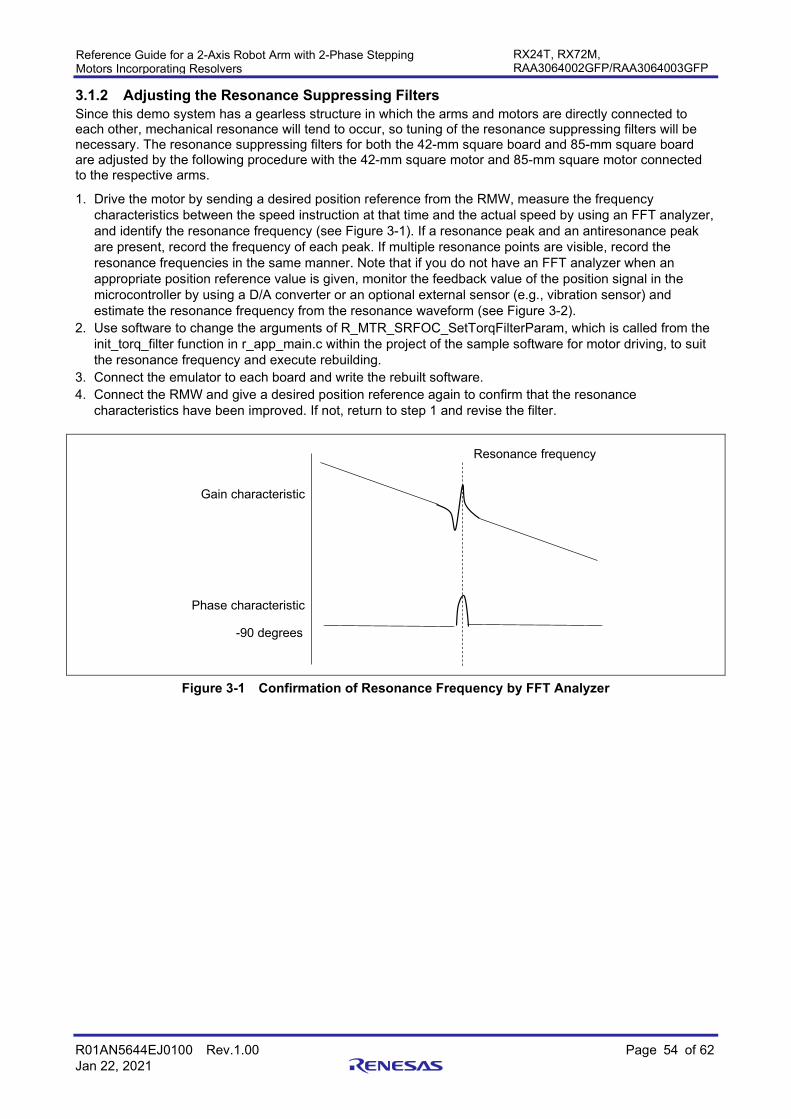
R01AN5644EJ0100 Rev.1.00 Page 54 of 62 Jan 22, 2021
Reference Guide for a 2-Axis Robot Arm with 2-Phase Stepping Motors Incorporating Resolvers
RX24T, RX72M, RAA3064002GFP/RAA3064003GFP
3.1.2 Adjusting the Resonance Suppressing Filters Since this demo system has a gearless structure in which the arms and motors are directly connected to each other, mechanical resonance will tend to occur, so tuning of the resonance suppressing filters will be necessary. The resonance suppressing filters for both the 42-mm square board and 85-mm square board are adjusted by the following procedure with the 42-mm square motor and 85-mm square motor connected to the respective arms.
1. Drive the motor by sending a desired position reference from the RMW, measure the frequency characteristics between the speed instruction at that time and the actual speed by using an FFT analyzer, and identify the resonance frequency (see Figure 3-1). If a resonance peak and an antiresonance peak are present, record the frequency of each peak. If multiple resonance points are visible, record the resonance frequencies in the same manner. Note that if you do not have an FFT analyzer when an appropriate position reference value is given, monitor the feedback value of the position signal in the microcontroller by using a D/A converter or an optional external sensor (e.g., vibration sensor) and estimate the resonance frequency from the resonance waveform (see Figure 3-2).
2. Use software to change the arguments of R_MTR_SRFOC_SetTorqFilterParam, which is called from the init_torq_filter function in r_app_main.c within the project of the sample software for motor driving, to suit the resonance frequency and execute rebuilding.
3. Connect the emulator to each board and write the rebuilt software. 4. Connect the RMW and give a desired position reference again to confirm that the resonance
characteristics have been improved. If not, return to step 1 and revise the filter.
Figure 3-1 Confirmation of Resonance Frequency by FFT Analyzer
Gain characteristic
Phase characteristic
-90 degrees
Resonance frequency
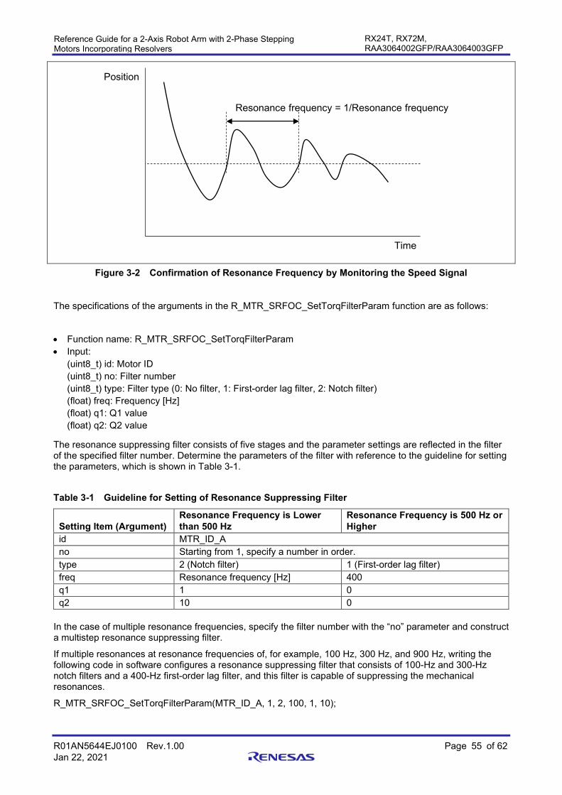
R01AN5644EJ0100 Rev.1.00 Page 55 of 62 Jan 22, 2021
Reference Guide for a 2-Axis Robot Arm with 2-Phase Stepping Motors Incorporating Resolvers
RX24T, RX72M, RAA3064002GFP/RAA3064003GFP
Figure 3-2 Confirmation of Resonance Frequency by Monitoring the Speed Signal
The specifications of the arguments in the R_MTR_SRFOC_SetTorqFilterParam function are as follows:
• Function name: R_MTR_SRFOC_SetTorqFilterParam • Input:
(uint8_t) id: Motor ID (uint8_t) no: Filter number (uint8_t) type: Filter type (0: No filter, 1: First-order lag filter, 2: Notch filter) (float) freq: Frequency [Hz] (float) q1: Q1 value (float) q2: Q2 value
The resonance suppressing filter consists of five stages and the parameter settings are reflected in the filter of the specified filter number. Determine the parameters of the filter with reference to the guideline for setting the parameters, which is shown in Table 3-1.
Table 3-1 Guideline for Setting of Resonance Suppressing Filter
Setting Item (Argument) Resonance Frequency is Lower than 500 Hz
Resonance Frequency is 500 Hz or Higher
id MTR_ID_A no Starting from 1, specify a number in order. type 2 (Notch filter) 1 (First-order lag filter) freq Resonance frequency [Hz] 400 q1 1 0 q2 10 0
In the case of multiple resonance frequencies, specify the filter number with the “no” parameter and construct a multistep resonance suppressing filter.
If multiple resonances at resonance frequencies of, for example, 100 Hz, 300 Hz, and 900 Hz, writing the following code in software configures a resonance suppressing filter that consists of 100-Hz and 300-Hz notch filters and a 400-Hz first-order lag filter, and this filter is capable of suppressing the mechanical resonances.
R_MTR_SRFOC_SetTorqFilterParam(MTR_ID_A, 1, 2, 100, 1, 10);
Position
Resonance frequency = 1/Resonance frequency
Time

R01AN5644EJ0100 Rev.1.00 Page 56 of 62 Jan 22, 2021
Reference Guide for a 2-Axis Robot Arm with 2-Phase Stepping Motors Incorporating Resolvers
RX24T, RX72M, RAA3064002GFP/RAA3064003GFP
R_MTR_SRFOC_SetTorqFilterParam(MTR_ID_A, 2, 2, 300, 1, 10);
R_MTR_SRFOC_SetTorqFilterParam(MTR_ID_A, 3, 1, 400, 0, 0);

R01AN5644EJ0100 Rev.1.00 Page 57 of 62 Jan 22, 2021
Reference Guide for a 2-Axis Robot Arm with 2-Phase Stepping Motors Incorporating Resolvers
RX24T, RX72M, RAA3064002GFP/RAA3064003GFP
3.2 Demonstrations by GUI After tuning of the demo system has completed, proceed with training in the demo system by running the demonstrations. Figure 3-3 shows a general flow up to the point of running the demonstrations.
Figure 3-3 General Flow up to Demonstrations
3.2.1 Preparations Prepare for operation using the following procedure. See section 1.3, NC Board, for the specifications for connection to the NC board.
1. Connect the NC board and an emulator and write the NC software (RobotArm_rx72m.mot) to the NC board.
2. After software has been written, disconnect the emulator from the NC board and connect the NC board to the PC with a USB cable.
3. Start the GUI up in the PC (see section 1.6). 3.2.2 Registration of Work Origin Set the coordinates to serve as a base (work origin) before training. The work origin is registered with the procedure shown in Figure 3-4. The work origin absolutely needs to be set when power is turned on but this manipulation can be skipped by saving the contents of the setup_workzeroangle command in a text file and reading the text file containing the command contents when power is turned on.
Figure 3-4 Procedure for Registering the Work Origin

R01AN5644EJ0100 Rev.1.00 Page 58 of 62 Jan 22, 2021
Reference Guide for a 2-Axis Robot Arm with 2-Phase Stepping Motors Incorporating Resolvers
RX24T, RX72M, RAA3064002GFP/RAA3064003GFP
3.2.3 Training Training is handled by the procedure shown in Figure 3-5. Move the arm to a desired point by hand, read the coordinates by executing a command in the GUI, and then write the desired operations based on the coordinates that were read out.
Saving the input command in a text file allows omission of the trouble of re-training by reading the text file from the next time. Note that the application note "R01AN5662EJ0100". provides a reference to the usable commands. For reference, Figure 3-6 shows an example of training to move through the shape of the numeral 8 and Figure 3-7 shows a training example for moving through the shape of the letter M.
Figure 3-5 Training Procedure

R01AN5644EJ0100 Rev.1.00 Page 59 of 62 Jan 22, 2021
Reference Guide for a 2-Axis Robot Arm with 2-Phase Stepping Motors Incorporating Resolvers
RX24T, RX72M, RAA3064002GFP/RAA3064003GFP
Example: Trajectory operation of numeral 8
Figure 3-6 Training for the Trajectory of Numeral 8
Example: Trajectory operation of letter M
Figure 3-7 Training for the Trajectory of Letter M

R01AN5644EJ0100 Rev.1.00 Page 60 of 62 Jan 22, 2021
Reference Guide for a 2-Axis Robot Arm with 2-Phase Stepping Motors Incorporating Resolvers
RX24T, RX72M, RAA3064002GFP/RAA3064003GFP
3.2.4 Demonstrations The demo system can execute the training operations with the method shown in Figure 3-8. Another method is to read a text file to which the training contents have been written in advance, as shown in Figure 3-9.
Figure 3-8 Method of Demonstrations
Figure 3-9 Method by Reading a Text File

R01AN5644EJ0100 Rev.1.00 Page 61 of 62 Jan 22, 2021
Reference Guide for a 2-Axis Robot Arm with 2-Phase Stepping Motors Incorporating Resolvers
RX24T, RX72M, RAA3064002GFP/RAA3064003GFP
3.3 Usage Notes • Since the GUI and NC software do not have fail-safe functions or functions for preventing accidents or
defects, the user needs to implement functions for ensuring safety as required. • The NC software is not capable of determining the cause of malfunctions or an unexpected stop of
operation. In such a case, issue a reset. • When using the move_xxx command to stop operation, setting the end flag to 0 makes the motor operate
with acceleration = ∞, so vibration will occur. The position is shifted from the specified coordinates if operation is stopped in such a manner. Therefore, the end flag should be set to 1 when operation is to be stopped.
• When combining the move_xxx commands to change the traveling direction, setting the end flag to 0 makes the motor operate with acceleration = ∞ and vibration will occur. Therefore, when combining operations (for example, continuous operation such as straight line ↔ arc or arc ↔ arc) while the end flag is set to 0, make the direction be changed smoothly.

R01AN5644EJ0100 Rev.1.00 Page 62 of 62 Jan 22, 2021
Reference Guide for a 2-Axis Robot Arm with 2-Phase Stepping Motors Incorporating Resolvers
RX24T, RX72M, RAA3064002GFP/RAA3064003GFP
Revision History
Rev. Date Description Page Summary
1.00 Jan 22, 2021 First edition issued

General Precautions in the Handling of Microprocessing Unit and Microcontroller Unit Products The following usage notes are applicable to all Microprocessing unit and Microcontroller unit products from Renesas. For detailed usage notes on the products covered by this document, refer to the relevant sections of the document as well as any technical updates that have been issued for the products.
1. Precaution against Electrostatic Discharge (ESD)
A strong electrical field, when exposed to a CMOS device, can cause destruction of the gate oxide and ultimately degrade the device operation. Steps
must be taken to stop the generation of static electricity as much as possible, and quickly dissipate it when it occurs. Environmental control must be
adequate. When it is dry, a humidifier should be used. This is recommended to avoid using insulators that can easily build up static electricity.
Semiconductor devices must be stored and transported in an anti-static container, static shielding bag or conductive material. All test and
measurement tools including work benches and floors must be grounded. The operator must also be grounded using a wrist strap. Semiconductor
devices must not be touched with bare hands. Similar precautions must be taken for printed circuit boards with mounted semiconductor devices. 2. Processing at power-on
The state of the product is undefined at the time when power is supplied. The states of internal circuits in the LSI are indeterminate and the states of
register settings and pins are undefined at the time when power is supplied. In a finished product where the reset signal is applied to the external reset
pin, the states of pins are not guaranteed from the time when power is supplied until the reset process is completed. In a similar way, the states of pins
in a product that is reset by an on-chip power-on reset function are not guaranteed from the time when power is supplied until the power reaches the
level at which resetting is specified. 3. Input of signal during power-off state
Do not input signals or an I/O pull-up power supply while the device is powered off. The current injection that results from input of such a signal or I/O
pull-up power supply may cause malfunction and the abnormal current that passes in the device at this time may cause degradation of internal
elements. Follow the guideline for input signal during power-off state as described in your product documentation. 4. Handling of unused pins
Handle unused pins in accordance with the directions given under handling of unused pins in the manual. The input pins of CMOS products are
generally in the high-impedance state. In operation with an unused pin in the open-circuit state, extra electromagnetic noise is induced in the vicinity of
the LSI, an associated shoot-through current flows internally, and malfunctions occur due to the false recognition of the pin state as an input signal
become possible. 5. Clock signals
After applying a reset, only release the reset line after the operating clock signal becomes stable. When switching the clock signal during program
execution, wait until the target clock signal is stabilized. When the clock signal is generated with an external resonator or from an external oscillator
during a reset, ensure that the reset line is only released after full stabilization of the clock signal. Additionally, when switching to a clock signal
produced with an external resonator or by an external oscillator while program execution is in progress, wait until the target clock signal is stable. 6. Voltage application waveform at input pin
Waveform distortion due to input noise or a reflected wave may cause malfunction. If the input of the CMOS device stays in the area between VIL
(Max.) and VIH (Min.) due to noise, for example, the device may malfunction. Take care to prevent chattering noise from entering the device when the
input level is fixed, and also in the transition period when the input level passes through the area between VIL (Max.) and VIH (Min.). 7. Prohibition of access to reserved addresses
Access to reserved addresses is prohibited. The reserved addresses are provided for possible future expansion of functions. Do not access these
addresses as the correct operation of the LSI is not guaranteed. 8. Differences between products
Before changing from one product to another, for example to a product with a different part number, confirm that the change will not lead to problems.
The characteristics of a microprocessing unit or microcontroller unit products in the same group but having a different part number might differ in terms
of internal memory capacity, layout pattern, and other factors, which can affect the ranges of electrical characteristics, such as characteristic values,
operating margins, immunity to noise, and amount of radiated noise. When changing to a product with a different part number, implement a system-
evaluation test for the given product.

© 2020 Renesas Electronics Corporation. All rights reserved.
Notice 1. Descriptions of circuits, software and other related information in this document are provided only to illustrate the operation of semiconductor products
and application examples. You are fully responsible for the incorporation or any other use of the circuits, software, and information in the design of your product or system. Renesas Electronics disclaims any and all liability for any losses and damages incurred by you or third parties arising from the use of these circuits, software, or information.
2. Renesas Electronics hereby expressly disclaims any warranties against and liability for infringement or any other claims involving patents, copyrights, or other intellectual property rights of third parties, by or arising from the use of Renesas Electronics products or technical information described in this document, including but not limited to, the product data, drawings, charts, programs, algorithms, and application examples.
3. No license, express, implied or otherwise, is granted hereby under any patents, copyrights or other intellectual property rights of Renesas Electronics or others.
4. You shall be responsible for determining what licenses are required from any third parties, and obtaining such licenses for the lawful import, export, manufacture, sales, utilization, distribution or other disposal of any products incorporating Renesas Electronics products, if required.
5. You shall not alter, modify, copy, or reverse engineer any Renesas Electronics product, whether in whole or in part. Renesas Electronics disclaims any and all liability for any losses or damages incurred by you or third parties arising from such alteration, modification, copying or reverse engineering.
6. Renesas Electronics products are classified according to the following two quality grades: “Standard” and “High Quality”. The intended applications for each Renesas Electronics product depends on the product’s quality grade, as indicated below. "Standard": Computers; office equipment; communications equipment; test and measurement equipment; audio and visual equipment; home
electronic appliances; machine tools; personal electronic equipment; industrial robots; etc. "High Quality": Transportation equipment (automobiles, trains, ships, etc.); traffic control (traffic lights); large-scale communication equipment; key
financial terminal systems; safety control equipment; etc. Unless expressly designated as a high reliability product or a product for harsh environments in a Renesas Electronics data sheet or other Renesas Electronics document, Renesas Electronics products are not intended or authorized for use in products or systems that may pose a direct threat to human life or bodily injury (artificial life support devices or systems; surgical implantations; etc.), or may cause serious property damage (space system; undersea repeaters; nuclear power control systems; aircraft control systems; key plant systems; military equipment; etc.). Renesas Electronics disclaims any and all liability for any damages or losses incurred by you or any third parties arising from the use of any Renesas Electronics product that is inconsistent with any Renesas Electronics data sheet, user’s manual or other Renesas Electronics document.
7. No semiconductor product is absolutely secure. Notwithstanding any security measures or features that may be implemented in Renesas Electronics hardware or software products, Renesas Electronics shall have absolutely no liability arising out of any vulnerability or security breach, including but not limited to any unauthorized access to or use of a Renesas Electronics product or a system that uses a Renesas Electronics product. RENESAS ELECTRONICS DOES NOT WARRANT OR GUARANTEE THAT RENESAS ELECTRONICS PRODUCTS, OR ANY SYSTEMS CREATED USING RENESAS ELECTRONICS PRODUCTS WILL BE INVULNERABLE OR FREE FROM CORRUPTION, ATTACK, VIRUSES, INTERFERENCE, HACKING, DATA LOSS OR THEFT, OR OTHER SECURITY INTRUSION (“Vulnerability Issues”). RENESAS ELECTRONICS DISCLAIMS ANY AND ALL RESPONSIBILITY OR LIABILITY ARISING FROM OR RELATED TO ANY VULNERABILITY ISSUES. FURTHERMORE, TO THE EXTENT PERMITTED BY APPLICABLE LAW, RENESAS ELECTRONICS DISCLAIMS ANY AND ALL WARRANTIES, EXPRESS OR IMPLIED, WITH RESPECT TO THIS DOCUMENT AND ANY RELATED OR ACCOMPANYING SOFTWARE OR HARDWARE, INCLUDING BUT NOT LIMITED TO THE IMPLIED WARRANTIES OF MERCHANTABILITY, OR FITNESS FOR A PARTICULAR PURPOSE.
8. When using Renesas Electronics products, refer to the latest product information (data sheets, user’s manuals, application notes, “General Notes for Handling and Using Semiconductor Devices” in the reliability handbook, etc.), and ensure that usage conditions are within the ranges specified by Renesas Electronics with respect to maximum ratings, operating power supply voltage range, heat dissipation characteristics, installation, etc. Renesas Electronics disclaims any and all liability for any malfunctions, failure or accident arising out of the use of Renesas Electronics products outside of such specified ranges.
9. Although Renesas Electronics endeavors to improve the quality and reliability of Renesas Electronics products, semiconductor products have specific characteristics, such as the occurrence of failure at a certain rate and malfunctions under certain use conditions. Unless designated as a high reliability product or a product for harsh environments in a Renesas Electronics data sheet or other Renesas Electronics document, Renesas Electronics products are not subject to radiation resistance design. You are responsible for implementing safety measures to guard against the possibility of bodily injury, injury or damage caused by fire, and/or danger to the public in the event of a failure or malfunction of Renesas Electronics products, such as safety design for hardware and software, including but not limited to redundancy, fire control and malfunction prevention, appropriate treatment for aging degradation or any other appropriate measures. Because the evaluation of microcomputer software alone is very difficult and impractical, you are responsible for evaluating the safety of the final products or systems manufactured by you.
10. Please contact a Renesas Electronics sales office for details as to environmental matters such as the environmental compatibility of each Renesas Electronics product. You are responsible for carefully and sufficiently investigating applicable laws and regulations that regulate the inclusion or use of controlled substances, including without limitation, the EU RoHS Directive, and using Renesas Electronics products in compliance with all these applicable laws and regulations. Renesas Electronics disclaims any and all liability for damages or losses occurring as a result of your noncompliance with applicable laws and regulations.
11. Renesas Electronics products and technologies shall not be used for or incorporated into any products or systems whose manufacture, use, or sale is prohibited under any applicable domestic or foreign laws or regulations. You shall comply with any applicable export control laws and regulations promulgated and administered by the governments of any countries asserting jurisdiction over the parties or transactions.
12. It is the responsibility of the buyer or distributor of Renesas Electronics products, or any other party who distributes, disposes of, or otherwise sells or transfers the product to a third party, to notify such third party in advance of the contents and conditions set forth in this document.
13. This document shall not be reprinted, reproduced or duplicated in any form, in whole or in part, without prior written consent of Renesas Electronics. 14. Please contact a Renesas Electronics sales office if you have any questions regarding the information contained in this document or Renesas
Electronics products.
(Note1) “Renesas Electronics” as used in this document means Renesas Electronics Corporation and also includes its directly or indirectly controlled subsidiaries.
(Note2) “Renesas Electronics product(s)” means any product developed or manufactured by or for Renesas Electronics. (Rev.5.0-1 October 2020)
Corporate Headquarters Contact information TOYOSU FORESIA, 3-2-24 Toyosu, Koto-ku, Tokyo 135-0061, Japan www.renesas.com
For further information on a product, technology, the most up-to-date version of a document, or your nearest sales office, please visit: www.renesas.com/contact/.
Trademarks Renesas and the Renesas logo are trademarks of Renesas Electronics Corporation. All trademarks and registered trademarks are the property of their respective owners.