Reference Guide - CenquipThe FCR PRIMA T2 (CR-IR 392) Reference Guide (hereafter referred to as this...
64
This Reference Guide describes details on how to operate the FCR PRIMA T2 (CR-IR 392) and cautions to be observed when operating it. Please read the Reference Guide thoroughly before actually operating the FCR PRIMA T2 (CR-IR 392) system. After reading this manual, store it nearby the FCR PRIMA T2 (CR-IR 392) so that you can see it whenever necessary. For Safe Operation Product Overview Basic Operation Troubleshooting Care and Maintenance Appendix Maintenance and Inspection Index 897N102547 (CR-IR 392) Reference Guide 1st Edition
Transcript of Reference Guide - CenquipThe FCR PRIMA T2 (CR-IR 392) Reference Guide (hereafter referred to as this...
This Reference Guide describes details on how to operate the FCR PRIMA T2 (CR-IR 392) and cautions to be observed when operating it.Please read the Reference Guide thoroughly before actually operating the FCR PRIMA T2 (CR-IR 392) system. After reading this manual, store it nearby the FCR PRIMA T2 (CR-IR 392) so that you can see it whenever necessary.
For Safe Operation
Product Overview
Basic Operation
Troubleshooting
Care and Maintenance
Appendix
Maintenance and Inspection
Index
897N102547
(CR-IR 392)
Reference Guide1st Edition

ii FCR PRIMA T2 Reference Guide 897N102547
iiiFCR PRIMA T2 Reference Guide 897N102547
IntroductionThe indications for use of the FCR PRIMA T2 (CR-IR 392) Image Reader with Imaging Plate (IP) reading is the identification, capture, digitization, and processing of diagnostic X-ray images of human anatomy, and associating patient and exam identification with the images.This Reference Guide is applicable to the following software.• FCR PRIMA T2 main unit software V2.0 or later
The FCR PRIMA T2 (CR-IR 392) is equipment designed to scan an X-ray image formed on an imaging plate (IP), being an image reading unit used for the CR-IR 392 Fuji Computed Radiography system. An IP is used as an X-ray image detector. It records the image information of an image captured by an X-ray exposure.The FCR PRIMA T2 (CR-IR 392) Reference Guide (hereafter referred to as this manual) provides information necessary for the use of the FCR PRIMA T2 (CR-IR 392), including an overview of the FCR PRIMA T2 (CR-IR 392), operation instructions and operation precautions, daily checks and maintenance, and so on.Accompanying documents were originally drafted in the English language.Installation may only be conducted by authorized service personal.
CAUTION
1 No part or all of this manual may be reproduced in any form without prior permission.2 The information contained in this manual may be subject to change without prior notice.3 FUJIFILM Corporation shall not be liable for malfunctions and damages resulting from
installation, relocation, remodeling, maintenance, and repair performed by other than dealers specified by FUJIFILM Corporation.
4 FUJIFILM Corporation shall not be liable for malfunctions and damages of FUJIFILM Corporation products due to products of other manufacturers not supplied by FUJIFILM Corporation.
5 FUJIFILM Corporation shall not be liable for malfunctions and damages resulting from remodeling, maintenance, and repair using repair parts other than those specified by FUJIFILM Corporation.
6 FUJIFILM Corporation shall not be liable for malfunctions and damages resulting from negligence of precautions and operating methods contained in this manual.
7 FUJIFILM Corporation shall not be liable for malfunctions and damages resulting from use under environment conditions outside the range of using conditions for this product such as power supply, installation environment, etc. contained in this manual.
8 FUJIFILM Corporation shall not be liable for malfunctions and damages resulting from natural disasters such as fires, earthquakes, floods, lightning, etc.
Caution: Rx Only in the United States (Federal law restricts this device to sale by or on the order of a physician).
TrademarkFCR is a trademark or a registered trademark of FUJIFILM Corporation.
Copyright © 2012 FUJIFILM Corporation. All rights reserved.
iv FCR PRIMA T2 Reference Guide 897N102547
How to Read This Manual
MarksInformation items to be observed when you are operating this system and the supplementary remarks are described in this manual with the respective marks.For the safe system operation, be sure to observe Warning/Caution.
WARNING Indicates hazardous situations that may lead to serious injury or even death if the precaution is not or could not be followed.
CAUTIONIndicates hazardous situations that may lead to mild or moderate injury or physical damages if the caution is not or cannot be followed.
HINT Shows an item helpful for further effective system operation.
Shows a more detailed operation method or an item that describes additional information.
vFCR PRIMA T2 Reference Guide 897N102547
Contents at a Glance
Chapter 1For Safe OperationThis chapter presents Warnings and Cautions you should observe for safe operation of the FCR PRIMA T2 (CR-IR 392).
Chapter 2Product OverviewThis chapter presents major features, unit names and functions of the FCR PRIMA T2 (CR-IR 392).
Chapter 3Basic OperationThis chapter provides instructions on how to start up/shut down the FCR PRIMA T2 (CR-IR 392) and how to read an image.
Chapter 4TroubleshootingThis chapter describes how to troubleshoot in the event of an error on the FCR PRIMA T2 (CR-IR 392), and provides explanations about a list of error codes each of which appears when an error occurs.
Chapter 5Care and MaintenanceThis chapter describes daily checks and maintenance you are advised to perform so that you can use the FCR PRIMA T2 (CR-IR 392) in optimum working conditions.
AppendixAppendix A SpecificationsAppendix B IP HandlingAppendix C Text Information Printed on FilmAppendix Z Precautions for Exposure
Maintenance and Inspection
Index
vi FCR PRIMA T2 Reference Guide 897N102547
ContentsIntroduction ...........................................................................................................................iiiHow to Read This Manual ....................................................................................................ivContents at a Glance ............................................................................................................ v
Chapter 1 For Safe Operation1.1 Precautions Before Operating This Equipment ....................................................... 1-11.2 Precautions to be Observed When Using the Electric Medical Equipment ............. 1-21.3 Safety ......................................................................................................................1-31.4 Electromagnetic Compatibility (EMC) ......................................................................1-51.5 Precautions to Take When Using the FCR PRIMA T2 (CR-IR 392) ........................ 1-91.6 Location of Each Label and Mark .......................................................................... 1-10
1.6.1 Locations ............................................................................................................... 1-101.6.2 Safety and Other Signs ......................................................................................... 1-12
Chapter 2 Product Overview2.1 Features of the FCR PRIMA T2 (CR-IR 392) .......................................................... 2-12.2 Units Names and the Functions .............................................................................. 2-3
2.2.1 FCR PRIMA T2 (CR-IR 392) Main Unit ...................................................................2-32.2.2 Operation Panel .......................................................................................................2-42.2.3 Operation Panel Display at the Time of Startup/Shutdown .....................................2-5
Chapter 3 Basic Operation3.1 Performing Erasure Before Use IPs ........................................................................ 3-13.2 System Startup/Shutdown and Image Reading (Console) ......................................3-2
3.2.1 Starting Up the System ...........................................................................................3-23.2.2 Shutting Down the System ......................................................................................3-33.2.3 Reading Cassette IP Images .................................................................................. 3-4
3.3 Starting Up/Shutting Down the FCR PRIMA T2 Main Unit ......................................3-53.3.1 Starting up the FCR PRIMA T2 main unit ...............................................................3-53.3.2 Shutting down the FCR PRIMA T2 main unit ......................................................... 3-6
Chapter 4 Troubleshooting4.1 Troubleshooting ....................................................................................................... 4-14.2 If the FCR PRIMA T2 Cannot be Powered ON .......................................................4-24.3 If the FCR PRIMA T2 Cannot be Powered OFF ......................................................4-34.4 When An Error Code Appears ................................................................................4-44.5 When Image Is Streaked .........................................................................................4-7
Chapter 5 Care and Maintenance5.1 About Performing Daily Checks and Maintenance .................................................. 5-15.2 Cleaning the Cassette Set Unit ...............................................................................5-25.3 Users Check Sheet .................................................................................................5-35.4 About Preventive Maintenance ................................................................................5-4
viiFCR PRIMA T2 Reference Guide 897N102547
Appendix A SpecificationsA.1 Specifications ..........................................................................................................A-1
A.1.1 Details of Equipment Specifications ....................................................................... A-1A.1.2 Operating Performance .......................................................................................... A-2A.1.3 Applicable Safety Standard .................................................................................... A-3
A.2 External View and Weight ...................................................................................... A-4
Appendix B IP HandlingB.1 IP Image Erasure Operation ....................................................................................B-1B.2 Handling, Daily Care, and Storage of IPs ................................................................B-2
Appendix C Text Information Printed on FilmC.1 Text Information Printed on Film ..............................................................................C-1
Appendix Z Precautions for ExposureZ.1 Precautions to Take Before Exposure ..................................................................... Z-1
Z.1.1 Using the Bucky’s Device ........................................................................................Z-1Z.1.2 Precautions to Observe Before Using an IP ............................................................Z-1
Z.2 Precautions to Take in Each Mode .......................................................................... Z-2Z.2.1 Precautions for Exposure in the AUTO MODE .......................................................Z-2Z.2.2 Precautions for Exposure in the SEMI-AUTO MODE .............................................Z-4Z.2.3 Precautions for Exposure in the SEMI-X MODE .....................................................Z-5Z.2.4 Precautions for Exposure in the FIX MODE ............................................................Z-5
Z.3 Other Precautions ...................................................................................................Z-6
Maintenance and Inspection
Index

viii FCR PRIMA T2 Reference Guide 897N102547
1-1FCR PRIMA T2 Reference Guide 897N102547
For Safe Operation
1
Chapter 1 For Safe Operation
1.1 Precautions Before Operating This Equipment
Before using this equipment, please read this page carefully so that you can operate it correctly.Whenever you operate this equipment, be sure to observe those precautions. Failure to do so may cause you to subject to injuries or property damage to occur.
This system is classified as a medical device under EC Directive 93/42/EEC.This equipment has been designed on the assumption that the patient would not come into direct contact with it or for operation by appropriately trained operator.
Process waste correctly, as stipulated by local law or any regulations that apply.
1-2 FCR PRIMA T2 Reference Guide 897N102547
For Safe Operation
1
1.2 Precautions to be Observed When Using the Electric Medical Equipment
We ask that you observe these usage precautions and use the equipment correctly.
1. This equipment should be used only by people who have the proper skills.2. Observe the following precautions when installing the equipment.
2-1. Install the equipment where water will not splash it.2-2. Install the equipment where it will not be adversely affected by air pressure, temperature,
humidity, ventilation, sunlight, dust or the presence of salt, sulfur or like substances in the atmosphere.
2-3. Make sure the equipment will remain in stable condition on a level surface and not be subjected to vibration or shock.
2-4. Do not install the equipment in places where chemicals are stored or gases emitted.2-5. Make sure that the power frequency, voltage and power consumption are appropriate.2-6. Connect the ground wire correctly.
3. Observe the following precautions before beginning to use the device.3-1. Inspect the switch contacts, polarities, dial settings and meters and confirm that the
equipment is functioning properly.3-2. Confirm that the ground wire has been completely connected.3-3. Make sure that all cords have been connected properly and safely.3-4. Be aware that correct diagnosis can be hindered and danger can result from using different
pieces of equipment together.4. Observe the following precautions after using the equipment.
4-1. Using the established procedure, restore the operation switches, dials, etc., to what they were prior to use and then turn the power off.
4-2. When unplugging cords, do not pull on the body of the cord itself or apply unnecessary force.
4-3. After using the accessories, recollect them and put them back in order.5. If there is trouble with the equipment, do not attempt to fix it randomly. Instead, do what is
indicated and entrust repairs to a professional.6. Do not remodel the equipment.7. Maintenance and Inspection
7-1. Make inspect the equipment and parts periodically.7-2. If the equipment has not been used for a long time, make sure that it operates normally and
safely prior to using it again.8. Other Items
8-1. When subjecting patients (particularly infants and pregnant women) to radiation, make sure not to exceed the necessary time and dose. Also, ensure that radiation is contained within the region for exposure.
8-2. Follow the Reference Guide and operate the equipment correctly.
1-3FCR PRIMA T2 Reference Guide 897N102547
For Safe Operation
1
1.3 SafetyPrior to using this equipment, please carefully read safety precautions presented herein for you to operate it correctly.
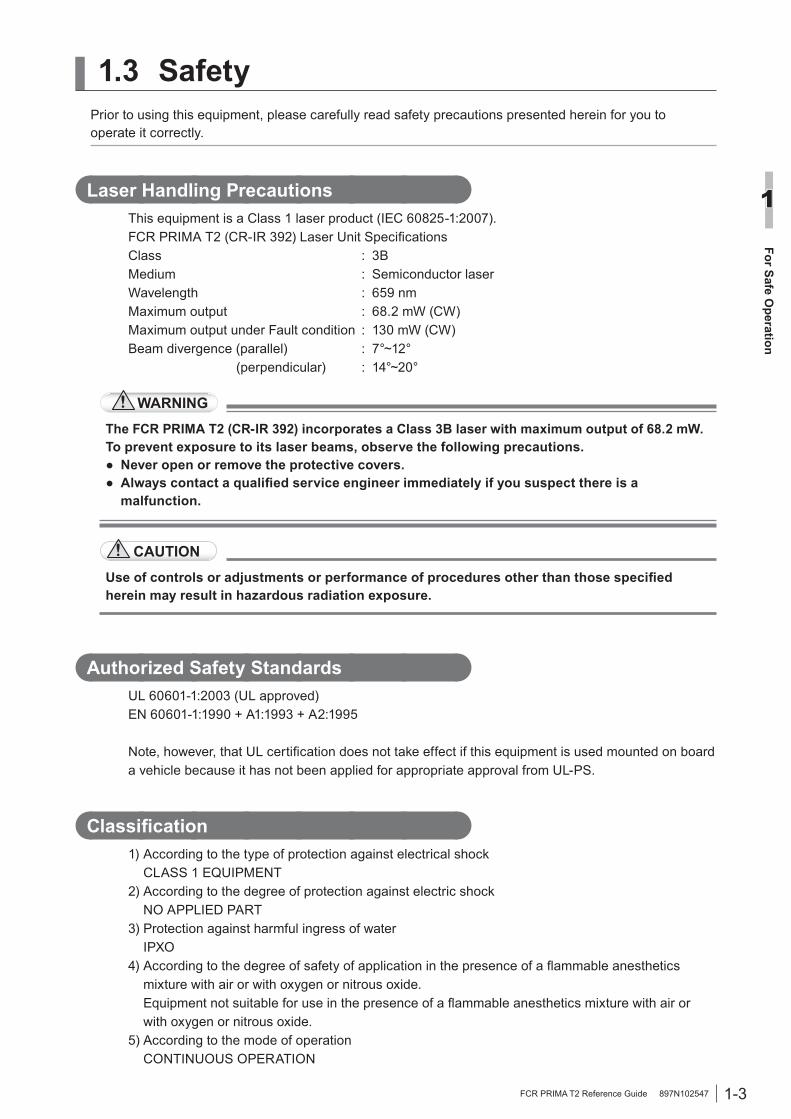
Laser Handling PrecautionsThis equipment is a Class 1 laser product (IEC 60825-1:2007).FCR PRIMA T2 (CR-IR 392) Laser Unit SpecificationsClass : 3BMedium : Semiconductor laserWavelength : 659 nmMaximum output : 68.2 mW (CW)Maximum output under Fault condition : 130 mW (CW)Beam divergence (parallel) : 7°~12° (perpendicular) : 14°~20°
WARNING
The FCR PRIMA T2 (CR-IR 392) incorporates a Class 3B laser with maximum output of 68.2 mW.To prevent exposure to its laser beams, observe the following precautions.● Never open or remove the protective covers.● Always contact a qualified service engineer immediately if you suspect there is a
malfunction.
CAUTION
Use of controls or adjustments or performance of procedures other than those specified herein may result in hazardous radiation exposure.
Authorized Safety StandardsUL 60601-1:2003 (UL approved)EN 60601-1:1990 + A1:1993 + A2:1995
Note, however, that UL certification does not take effect if this equipment is used mounted on board a vehicle because it has not been applied for appropriate approval from UL-PS.
Classification1) According to the type of protection against electrical shock
CLASS 1 EQUIPMENT2) According to the degree of protection against electric shock
NO APPLIED PART3) Protection against harmful ingress of water
IPXO4) According to the degree of safety of application in the presence of a flammable anesthetics
mixture with air or with oxygen or nitrous oxide. Equipment not suitable for use in the presence of a flammable anesthetics mixture with air or with oxygen or nitrous oxide.
5) According to the mode of operation CONTINUOUS OPERATION

1-4 FCR PRIMA T2 Reference Guide 897N102547
For Safe Operation
1
General Precautions Against Electrical Shock
WARNINGThe service voltage of this equipment is 100 to 240 VAC.Instructions below must be followed to prevent an electrical shock to users.● Never open equipment covers. Do not touch high-voltage units of the equipment with your
hand, otherwise you may receive an electrical shock.● Install the equipment where no water may subject the equipment.● Ensure that the equipment is properly grounded.● Check that all the cables are properly and perfectly connected.● When using the equipment within the environment where the patient may get into touch
with it, optionally connect additional protective earth conductor (FCR PRIMA T2 (CR-IR 392)).
● When using the equipment within the environment where the patient may get into touch with it, the user must not touch the equipment’s exterior, such as covers and metal sections, and the patient at the same time.

1-5FCR PRIMA T2 Reference Guide 897N102547
For Safe Operation
1
1.4 Electromagnetic Compatibility (EMC)This equipment has been tested and found to comply with the limits for medical devices to the IEC 60601-1-2:2001+Amd1:2004/EN 60601-1-2:2001+Amd1:2006.These limits are designed to provide reasonable protection against harmful interference in a typical medical installation.This equipment generates, uses and can radiate radio frequency energy and, if not installed and used in accordance with the instructions, may cause harmful interference to other devices in the vicinity.However, there is no guarantee that interference will not occur in a particular installation.If this equipment does cause harmful interference to other devices, which can be determined by tuning the equipment off and on, the user is encouraged to try to correct the interference by one or more of the following measures:• Reorient or relocate the receiving device.• Increase the separation between the equipment.• Connect the equipment into an outlet on a circuit different from that to which the other device(s)
are connected. Consult the manufacturer or field service technician for help.
Further information for IEC 60601-1-2:2001/EN 60601-1-2:2001• Medical electrical equipment needs special precautions regarding EMC and needs to be installed
and put into service according to the EMC information provided in the accompanying documents.• Portable and mobile RF communications equipment can affect medical electrical equipment.• Information regarding the cable affecting EMC is as follows.
Name General Specification
Network Cable Cat 5 or more, UTP type and straight cable.
• The use of accessories, transducers and cables other than those specified, with the exception of transducers and cables sold by FUJIFILM Corporation as replacement parts for internal components, may result in increased emissions or decreased immunity of the FCR PRIMA T2 (CR-IR 392).
• The FCR PRIMA T2 (CR-IR 392) should not be used adjacent to or stacked with other equipment.
If adjacent or stacked use is necessary, the FCR PRIMA T2 (CR-IR 392) should be observed to verify normal operation in the configuration in which it will be used.
1-6 FCR PRIMA T2 Reference Guide 897N102547
For Safe Operation
1
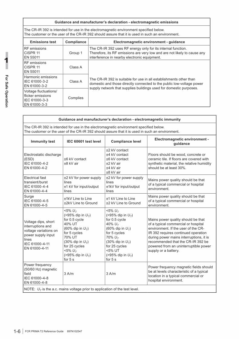
Guidance and manufacturer’s declaration - electromagnetic emissions
The CR-IR 392 is intended for use in the electromagnetic environment specified below. The customer or the user of the CR-IR 392 should assure that it is used in such an environment.
Emissions test Compliance Electromagnetic environment - guidance
RF emissionsCISPR 11EN 55011
Group 1The CR-IR 392 uses RF energy only for its internal function.Therefore, its RF emissions are very low and are not likely to cause any interference in nearby electronic equipment.
RF emissionsCISPR 11EN 55011
Class A
The CR-IR 392 is suitable for use in all establishments other than domestic and those directly connected to the public low-voltage power supply network that supplies buildings used for domestic purposes.
Harmonic emissionsIEC 61000-3-2EN 61000-3-2
Class A
Voltage fluctuations/flicker emissions IEC 61000-3-3EN 61000-3-3
Complies
Guidance and manufacturer’s declaration - electromagnetic immunity
The CR-IR 392 is intended for use in the electromagnetic environment specified below.The customer or the user of the CR-IR 392 should assure that it is used in such an environment.
Immunity test IEC 60601 test level Compliance level Electromagnetic environment - guidance
Electrostatic discharge(ESD)IEC 61000-4-2EN 61000-4-2
±6 kV contact±8 kV air
±2 kV contact±4 kV contact±6 kV contact±2 kV air±4 kV air±8 kV air
Floors should be wood, concrete or ceramic tile. If floors are covered with synthetic material, the relative humidity should be at least 30%.
Electrical fast transient/burstIEC 61000-4-4EN 61000-4-4
±2 kV for power supply lines±1 kV for input/output lines
±2 kV for power supply lines±1kV for input/output lines
Mains power quality should be that of a typical commercial or hospital environment.
SurgeIEC 61000-4-5EN 61000-4-5
±1kV Line to Line±2kV Line to Ground
±1 kV Line to Line±2 kV Line to Ground
Mains power quality should be that of a typical commercial or hospital environment.
Voltage dips, short interruptions and voltage variations on power supply input linesIEC 61000-4-11EN 61000-4-11
<5% UT(>95% dip in UT)for 0.5 cycle40% UT(60% dip in UT)for 5 cycles70% UT(30% dip in UT)for 25 cycles<5% UT(>95% dip in UT)for 5 s
<5% UT(>95% dip in UT)for 0.5 cycle40% UT(60% dip in UT)for 5 cycles70% UT(30% dip in UT)for 25 cycles<5% UT(>95% dip in UT)for 5 s
Mains power quality should be that of a typical commercial or hospital environment. If the user of the CR-IR 392 requires continued operation during power mains interruptions, it is recommended that the CR-IR 392 be powered from an uninterruptible power supply or a battery.
Power frequency (50/60 Hz) magnetic fieldIEC 61000-4-8EN 61000-4-8
3 A/m 3 A/m
Power frequency magnetic fields should be at levels characteristic of a typical location in a typical commercial or hospital environment.
NOTE: UT is the a.c. mains voltage prior to application of the test level.
1-7FCR PRIMA T2 Reference Guide 897N102547
For Safe Operation
1
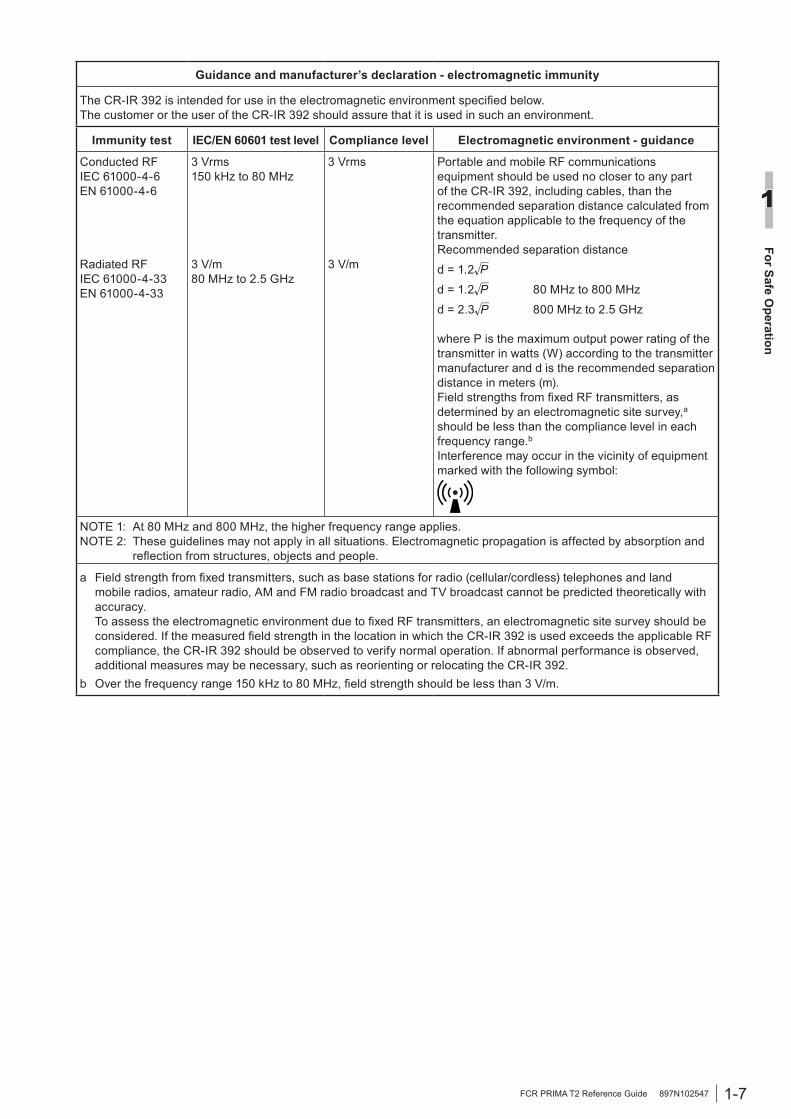
Guidance and manufacturer’s declaration - electromagnetic immunity
The CR-IR 392 is intended for use in the electromagnetic environment specified below.The customer or the user of the CR-IR 392 should assure that it is used in such an environment.
Immunity test IEC/EN 60601 test level Compliance level Electromagnetic environment - guidance
Conducted RFIEC 61000-4-6EN 61000-4-6
Radiated RFIEC 61000-4-33EN 61000-4-33
3 Vrms150 kHz to 80 MHz
3 V/m80 MHz to 2.5 GHz
3 Vrms
3 V/m
Portable and mobile RF communications equipment should be used no closer to any part of the CR-IR 392, including cables, than the recommended separation distance calculated from the equation applicable to the frequency of the transmitter.Recommended separation distance
d = 1.2
d = 1.2 80 MHz to 800 MHz
d = 2.3 800 MHz to 2.5 GHz
where P is the maximum output power rating of the transmitter in watts (W) according to the transmitter manufacturer and d is the recommended separation distance in meters (m).Field strengths from fixed RF transmitters, as determined by an electromagnetic site survey,a should be less than the compliance level in each frequency range.bInterference may occur in the vicinity of equipment marked with the following symbol:
NOTE 1: At 80 MHz and 800 MHz, the higher frequency range applies.NOTE 2: These guidelines may not apply in all situations. Electromagnetic propagation is affected by absorption and
reflection from structures, objects and people.
a Field strength from fixed transmitters, such as base stations for radio (cellular/cordless) telephones and land mobile radios, amateur radio, AM and FM radio broadcast and TV broadcast cannot be predicted theoretically with accuracy. To assess the electromagnetic environment due to fixed RF transmitters, an electromagnetic site survey should be considered. If the measured field strength in the location in which the CR-IR 392 is used exceeds the applicable RF compliance, the CR-IR 392 should be observed to verify normal operation. If abnormal performance is observed, additional measures may be necessary, such as reorienting or relocating the CR-IR 392.
b Over the frequency range 150 kHz to 80 MHz, field strength should be less than 3 V/m.

1-8 FCR PRIMA T2 Reference Guide 897N102547
For Safe Operation
1
Recommended separation distances betweenPortable and mobile RF communications equipment and the CR-IR 392
The CR-IR 392 is intended for use in the electromagnetic environment in which radiated RF disturbances are controlled.The customer or the user of the CR-IR 392 can help prevent electromagnetic interference by maintaining a minimum distance between portable and mobile RF communications equipment (transmitters) and the CR-IR 392 as recommended below, according to the maximum output power of the communications equipment.
Rated maximum output power of transmitter
W
Separation distance according to frequency of transmitterm
150 kHz to 80 MHzd = 1.2
80 MHz to 800 MHzd = 1.2
800 MHz to 2.5 GHzd = 2.3
0.01 0.12 0.12 0.23 0.1 0.38 0.38 0.73 1 1.2 1.2 2.3 10 3.8 3.8 7.3 100 12 12 23
For transmitters rated at a maximum output power not listed above, the recommended separation distance d in meters (m) can be estimated using the equation applicable to the frequency of the transmitter, where P is the maximum output power rating of the transmitter in watts (W) according to the transmitter manufacturer.
NOTE 1: At 80 MHz and 800 MHz, the separation distance for the higher frequency range applies.NOTE 2: These guidelines may not apply in all situations.
Electromagnetic propagation is affected by absorption and reflection from structures, objects and people.
1-9FCR PRIMA T2 Reference Guide 897N102547
For Safe Operation
1
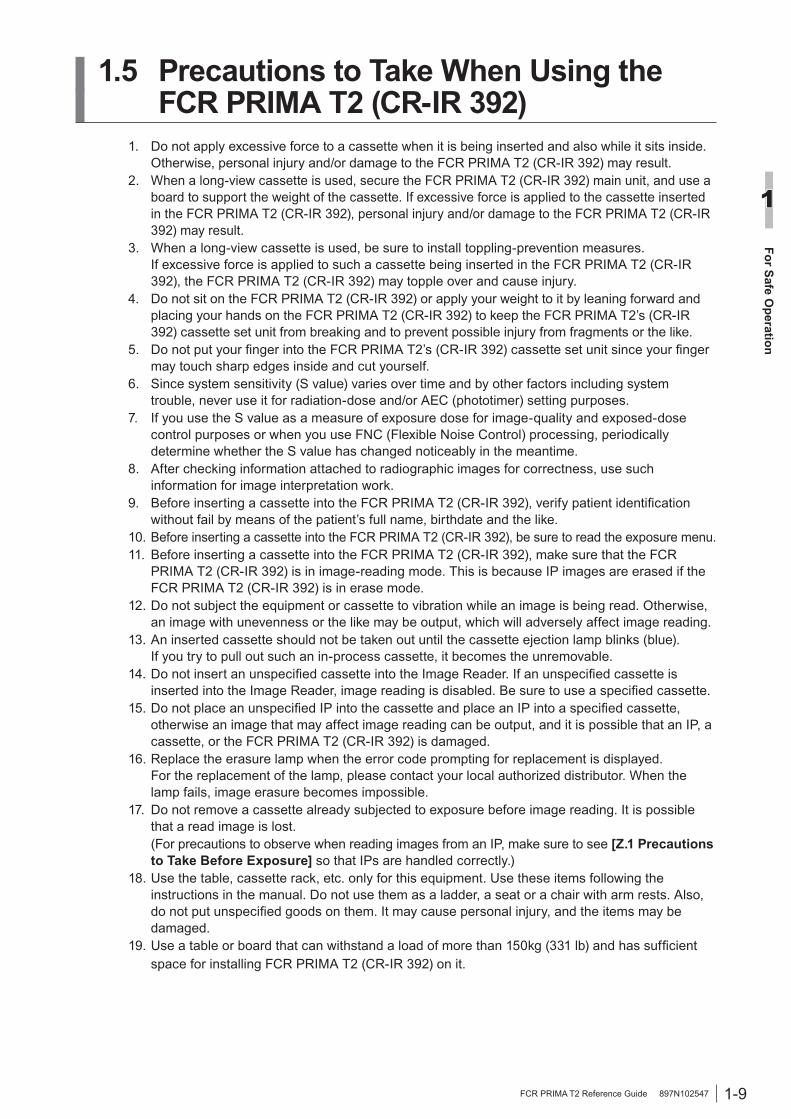
1.5 Precautions to Take When Using the FCR PRIMA T2 (CR-IR 392)
1. Do not apply excessive force to a cassette when it is being inserted and also while it sits inside. Otherwise, personal injury and/or damage to the FCR PRIMA T2 (CR-IR 392) may result.
2. When a long-view cassette is used, secure the FCR PRIMA T2 (CR-IR 392) main unit, and use a board to support the weight of the cassette. If excessive force is applied to the cassette inserted in the FCR PRIMA T2 (CR-IR 392), personal injury and/or damage to the FCR PRIMA T2 (CR-IR 392) may result.
3. When a long-view cassette is used, be sure to install toppling-prevention measures. If excessive force is applied to such a cassette being inserted in the FCR PRIMA T2 (CR-IR 392), the FCR PRIMA T2 (CR-IR 392) may topple over and cause injury.
4. Do not sit on the FCR PRIMA T2 (CR-IR 392) or apply your weight to it by leaning forward and placing your hands on the FCR PRIMA T2 (CR-IR 392) to keep the FCR PRIMA T2’s (CR-IR 392) cassette set unit from breaking and to prevent possible injury from fragments or the like.
5. Do not put your finger into the FCR PRIMA T2’s (CR-IR 392) cassette set unit since your finger may touch sharp edges inside and cut yourself.
6. Since system sensitivity (S value) varies over time and by other factors including system trouble, never use it for radiation-dose and/or AEC (phototimer) setting purposes.
7. If you use the S value as a measure of exposure dose for image-quality and exposed-dose control purposes or when you use FNC (Flexible Noise Control) processing, periodically determine whether the S value has changed noticeably in the meantime.
8. After checking information attached to radiographic images for correctness, use such information for image interpretation work.
9. Before inserting a cassette into the FCR PRIMA T2 (CR-IR 392), verify patient identification without fail by means of the patient’s full name, birthdate and the like.
10. Before inserting a cassette into the FCR PRIMA T2 (CR-IR 392), be sure to read the exposure menu.11. Before inserting a cassette into the FCR PRIMA T2 (CR-IR 392), make sure that the FCR
PRIMA T2 (CR-IR 392) is in image-reading mode. This is because IP images are erased if the FCR PRIMA T2 (CR-IR 392) is in erase mode.
12. Do not subject the equipment or cassette to vibration while an image is being read. Otherwise, an image with unevenness or the like may be output, which will adversely affect image reading.
13. An inserted cassette should not be taken out until the cassette ejection lamp blinks (blue). If you try to pull out such an in-process cassette, it becomes the unremovable.
14. Do not insert an unspecified cassette into the Image Reader. If an unspecified cassette is inserted into the Image Reader, image reading is disabled. Be sure to use a specified cassette.
15. Do not place an unspecified IP into the cassette and place an IP into a specified cassette, otherwise an image that may affect image reading can be output, and it is possible that an IP, a cassette, or the FCR PRIMA T2 (CR-IR 392) is damaged.
16. Replace the erasure lamp when the error code prompting for replacement is displayed. For the replacement of the lamp, please contact your local authorized distributor. When the lamp fails, image erasure becomes impossible.
17. Do not remove a cassette already subjected to exposure before image reading. It is possible that a read image is lost.
(For precautions to observe when reading images from an IP, make sure to see [Z.1 Precautions to Take Before Exposure] so that IPs are handled correctly.)
18. Use the table, cassette rack, etc. only for this equipment. Use these items following the instructions in the manual. Do not use them as a ladder, a seat or a chair with arm rests. Also, do not put unspecified goods on them. It may cause personal injury, and the items may be damaged.
19. Use a table or board that can withstand a load of more than 150kg (331 lb) and has sufficient space for installing FCR PRIMA T2 (CR-IR 392) on it.

1-10 FCR PRIMA T2 Reference Guide 897N102547
For Safe Operation
1
1.6 Location of Each Label and MarkShown below are the positions where the FCR PRIMA T2 (CR-IR 392) labels and mark are affi xed.
1.6.1 Locations● For USA only
Cassette Insertion Label
Hazardous Substances Compliance Label
IEC 60825-1:2007 Class 3B Panel Label(The dotted labels in the illustrations above are affixed to the inside of the cover and areinvisible from the outside.)
HHS Certification and Identification Label
Be sure to use the power cord our official dealer or local presentative provided.
Caution Label 2
Do not connect telephone lines to LAN connector. Only the IEC 60950-1/EN 60950-1 standard non-shielded cables are appropriate for connection to this connector.
Caution Label 3
Use this terminal to connect the additional protective ground wire.
Additional Protective Ground Mark
Rating Label
HHS Certification andIdentification Label
IEC 60825-1:2007 Class 3BPanel Label
Hazardous SubstancesCompliance Label
Rating Label
IEC 60825-1:2007 Class 3BPanel Label
IEC 60825-1:2007 Class 3BPanel Label
IEC 60825-1:2007 Class 3BPanel Label
Additional ProtectiveGround Mark
Caution Label 2
Caution Label 1
Caution Label 3Cassette Insertion Label
Caution Label 1

1-11FCR PRIMA T2 Reference Guide 897N102547
For Safe Operation
1
● For countries other than USA, China and Japan
Cassette Insertion Label
IEC 60825-1:2007 Class 3B Panel Label(The dotted labels in the illustrations above are affixed to the inside of the cover and areinvisible from the outside.)
HHS Certification and Identification Label
Be sure to use the power cord our official dealer or local presentative provided.
Caution Label 2
Do not connect telephone lines to LAN connector. Only the IEC 60950-1/EN 60950-1 standard non-shielded cables are appropriate for connection to this connector.
Caution Label 3
Use this terminal to connect the additional protective ground wire.
Additional Protective Ground Mark
Rating Label
HHS Certification andIdentification Label
Rating Label
IEC 60825-1:2007 Class 3BPanel Label
IEC 60825-1:2007 Class 3BPanel Label
Additional ProtectiveGround Mark
Caution Label 2
Caution Label 1
Caution Label 3Cassette Insertion Label
IEC 60825-1:2007 Class 3BPanel Label
IEC 60825-1:2007 Class 3BPanel Label
Caution Label 1
1-12 FCR PRIMA T2 Reference Guide 897N102547
For Safe Operation
1
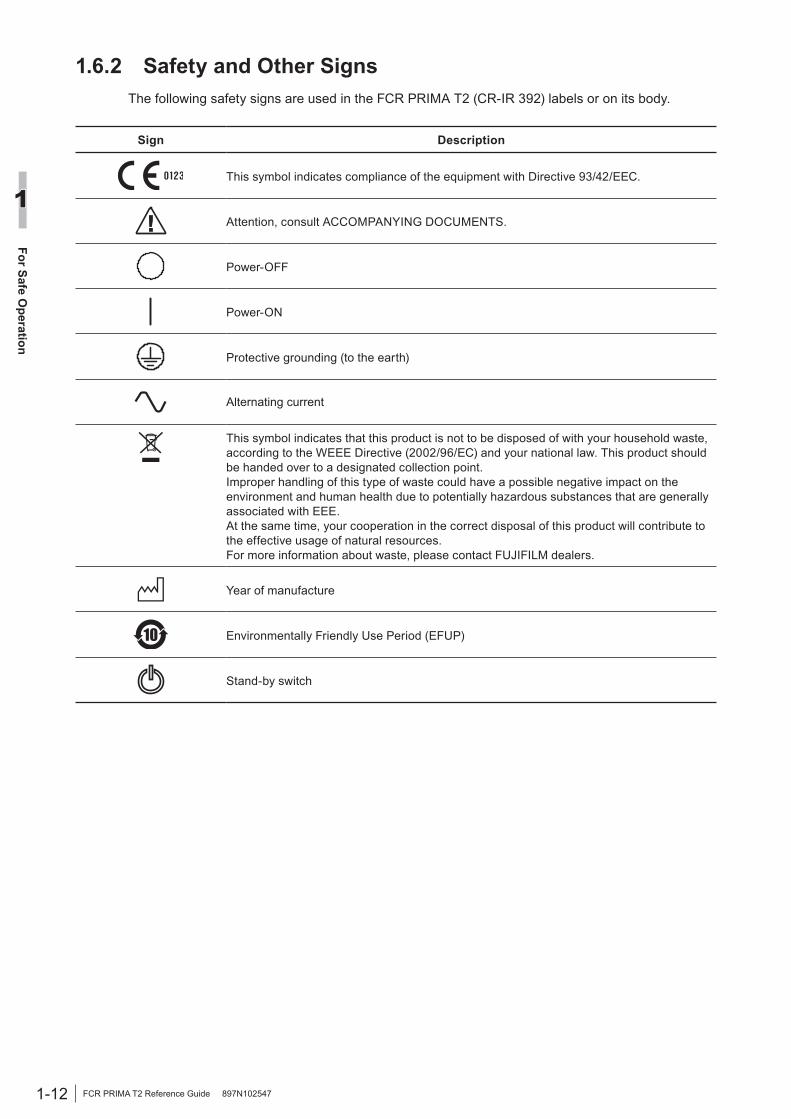
1.6.2 Safety and Other SignsThe following safety signs are used in the FCR PRIMA T2 (CR-IR 392) labels or on its body.
Sign Description
This symbol indicates compliance of the equipment with Directive 93/42/EEC.
Attention, consult ACCOMPANYING DOCUMENTS.
Power-OFF
Power-ON
Protective grounding (to the earth)
Alternating current
This symbol indicates that this product is not to be disposed of with your household waste, according to the WEEE Directive (2002/96/EC) and your national law. This product should be handed over to a designated collection point.Improper handling of this type of waste could have a possible negative impact on the environment and human health due to potentially hazardous substances that are generally associated with EEE.At the same time, your cooperation in the correct disposal of this product will contribute to the effective usage of natural resources.For more information about waste, please contact FUJIFILM dealers.
Year of manufacture
Environmentally Friendly Use Period (EFUP)
Stand-by switch
2-1FCR PRIMA T2 Reference Guide 897N102547
Product Overview
2
Chapter 2 Product Overview
2.1 Features of the FCR PRIMA T2 (CR-IR 392)The FCR PRIMA T2 (CR-IR 392) is equipment designed to read X-ray image information recorded on an imaging plate (IP). The IP is used as an X-ray image detector. It records the image information of an image captured by an X-ray exposure.This section explains features of a system employing the FCR PRIMA T2 (CR-IR 392) and FCR PRIMA T2 (CR-IR 392)-equipped system configuration examples.
The system can be used for chest, abdomen, bone, spine, head and other plain X-ray imaging, as well as spinal canal, bronchial tube, urinary organ, and other contrast medium X-ray imaging and X-ray tomography.
Major features of the system include:
1 By virtue of the effects of digital image processing, the system produces radiographs that have a high diagnostic value and are easy to interpret.
2 The system has a wide latitude for incident X-rays so that a large amount of X-ray diagnostic information can be obtained.
3 The system features high sensitivity, making it possible to reduce X-ray radiation doses or exposure to patients.
4 As the system takes an advantage of a wide latitude and an automatic sensitivity adjustment function, the image reading results of radiographs remain virtually unaffected by small variations in X-ray exposure conditions. Therefore, high image-density consistency can be obtained among radiographs.
5 Exposure information items that include patient information, anatomical regions and exposure menus can be entered on the console connected to the FCR PRIMA T2 (CR-IR 392).
6 Due to the compact size of the system, it can be installed in a relatively tight space.
7 The cassette can be inserted horizontally, making it easy to operate the system on the table.
■ Connectable console (Representative examples)The console shown below can be connected.• FCRView (CR-VW 674)• FCR PRIMA Console (CR-IR 391CL)• CR Console (CR-IR 348CL)

2-2 FCR PRIMA T2 Reference Guide 897N102547
Product Overview
2
■ Example of system configurationNetwork-connected to a Console or printer or the like, the FCR PRIMA T2 (CR-IR 392) also provides support to diversified system configurations. Illustrated below is the example of system configuration. Accessory equipment connected to the analog and digital interfaces must be in compliance with the respective nationally harmonized EN standards (i.e. EN 60950 for data processing equipment, EN 60065 for video equipment, EN 61010-1 for laboratory equipment, and EN 60601-1 for medical equipment). Furthermore all configurations shall comply with the system standard EN 60601-1-1. Everybody who connects additional equipment to the signal input part or signal output part configures a medical system, and is therefore, responsible that the system complies with the requirements of the system standard EN 60601-1-1. If in doubt, consult the technical services department or your local representative.
HUB
FCR PRIMA T2(CR-IR 392)
DRYPIX PRIMA(FM-DL 100 )
Console(CR-VW 674,
CR-IR 391CL or CR-IR 348CL)
2-3FCR PRIMA T2 Reference Guide 897N102547
Product Overview
2
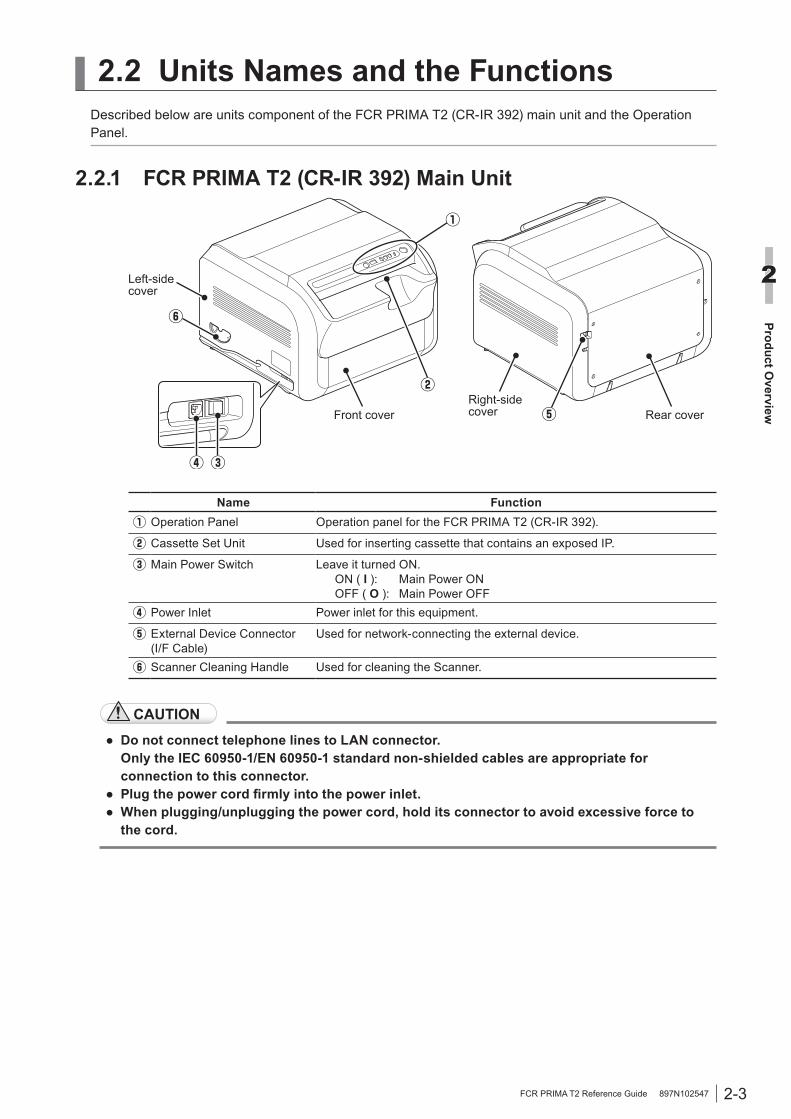
2.2 Units Names and the FunctionsDescribed below are units component of the FCR PRIMA T2 (CR-IR 392) main unit and the Operation Panel.
2.2.1 FCR PRIMA T2 (CR-IR 392) Main Unit
Left-sidecover
Front cover Rear coverRight-sidecover
Name FunctionOperation Panel Operation panel for the FCR PRIMA T2 (CR-IR 392).
Cassette Set Unit Used for inserting cassette that contains an exposed IP.
Main Power Switch Leave it turned ON. ON ( I ): Main Power ON OFF ( O ): Main Power OFF
Power Inlet Power inlet for this equipment.
External Device Connector(I/F Cable)
Used for network-connecting the external device.
Scanner Cleaning Handle Used for cleaning the Scanner.
CAUTION
● Do not connect telephone lines to LAN connector. Only the IEC 60950-1/EN 60950-1 standard non-shielded cables are appropriate for
connection to this connector.● Plug the power cord firmly into the power inlet. ● When plugging/unplugging the power cord, hold its connector to avoid excessive force to
the cord.

2-4 FCR PRIMA T2 Reference Guide 897N102547
Product Overview
2
2.2.2 Operation Panel
Name FunctionStand-by Switch Turns on/off the power to the FCR PRIMA T2 (CR-IR 392). This switch
is used when the FCR PRIMA T2 (CR-IR 392) is started up singly.When the buzzer sounds because of an error or detection of excessive amount of X-rays and this switch is pressed, the buzzer stops and the cassette lock is released.To turn off the unit, keep pressing the switch for about four seconds.
Status Display LED Indicates status of the unit.
: Initializing : End processing
: Console unconnected : Console connected
Blinking number
: Error/Warning indication
For details, see [4.4 When An Error Code Appears].Cassette Ready Lamp
Lights up (green) when it is ready for inserting a cassette. You can not insert the cassette when this lamp is off.When the lamp is on alternately with the Cassette Removal Lamp, an unprocessed cassette is ejected.
Cassette Removal Lamp
Blinks (blue) when it is ready for ejecting the processed cassette. Lights off when you remove the cassette. When this lamp is on alternately with the Cassette Ready Lamp, an unprocessed cassette is ejected.When this lamp is on alternately with the Excessive amount of X-ray Display Lamp, the Excessive amount of X-ray erasing-incomplete cassette is ejected. Press the Eraser Button and Perform an erasion. Note that it takes a lot of time to achieve erasure.
Excessive amount of X-ray Display Lamp
If X-ray of about 400 mR and over is detected, this lamp blinks alternately with the Cassette Removal Lamp, and the excessive amount of X-ray erasing-incomplete cassette is ejected. Press the Eraser Button and perform an erasion. Note that it takes a lot of time to achieve erasure.
If erasing is to be done later, remove the cassette. If the cassette is to be used the next time, always perform erasing after 16 hours have passed before using the cassette.
Power/Erasing Mode Indicator Lamp
Lights up with green color when the main power switch is set to ON and turns to orange color under the erasing mode.
Eraser Button Switches the mode from reading to erasing.When you erase IP images, press this button to switch to the erasing mode.
2-5FCR PRIMA T2 Reference Guide 897N102547
Product Overview
2
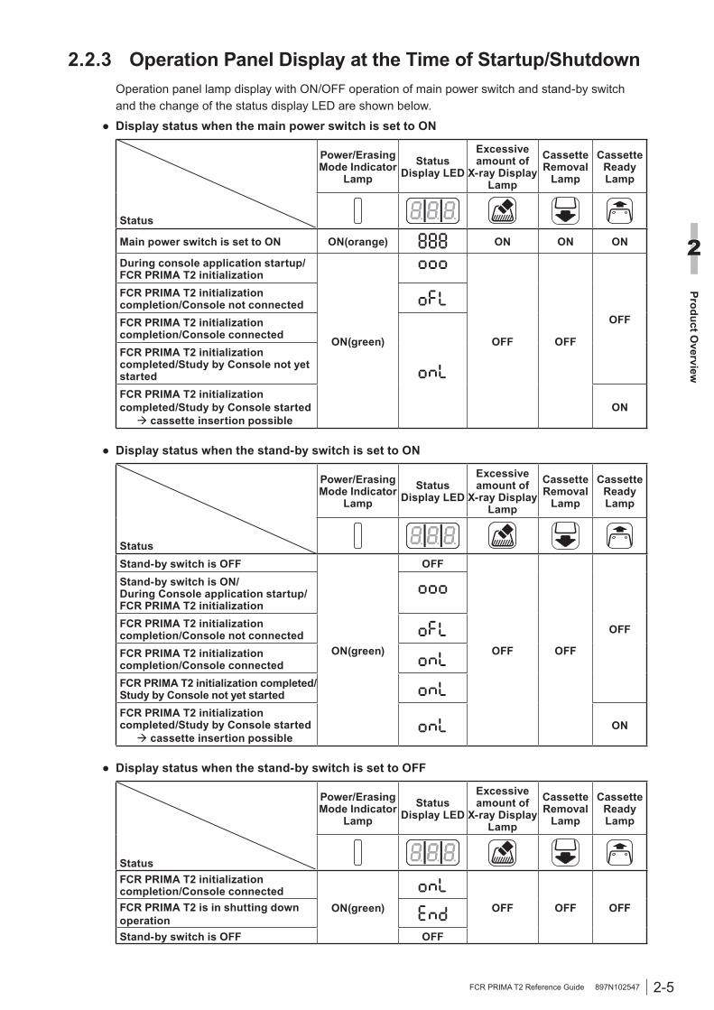
2.2.3 Operation Panel Display at the Time of Startup/ShutdownOperation panel lamp display with ON/OFF operation of main power switch and stand-by switch and the change of the status display LED are shown below.
● Display status when the main power switch is set to ON
Status
Power/Erasing Mode Indicator
LampStatus
Display LED
Excessive amount of
X-ray Display Lamp
Cassette Removal
Lamp
Cassette Ready Lamp
Main power switch is set to ON ON(orange) ON ON ON
During console application startup/FCR PRIMA T2 initialization
ON(green) OFF OFF
OFF
FCR PRIMA T2 initialization completion/Console not connected FCR PRIMA T2 initialization completion/Console connectedFCR PRIMA T2 initialization completed/Study by Console not yet startedFCR PRIMA T2 initialization completed/Study by Console started cassette insertion possible
ON
● Display status when the stand-by switch is set to ON
Status
Power/Erasing Mode Indicator
LampStatus
Display LED
Excessive amount of
X-ray Display Lamp
Cassette Removal
Lamp
Cassette Ready Lamp
Stand-by switch is OFF
ON(green)
OFF
OFF OFF
OFF
Stand-by switch is ON/During Console application startup/FCR PRIMA T2 initializationFCR PRIMA T2 initialization completion/Console not connectedFCR PRIMA T2 initialization completion/Console connectedFCR PRIMA T2 initialization completed/Study by Console not yet started FCR PRIMA T2 initialization completed/Study by Console started cassette insertion possible
ON
● Display status when the stand-by switch is set to OFF
Status
Power/Erasing Mode Indicator
LampStatus
Display LED
Excessive amount of
X-ray Display Lamp
Cassette Removal
Lamp
Cassette Ready Lamp
FCR PRIMA T2 initialization completion/Console connected
ON(green) OFF OFF OFFFCR PRIMA T2 is in shutting down operationStand-by switch is OFF OFF

2-6 FCR PRIMA T2 Reference Guide 897N102547
Product Overview
2

3-1
Basic O
peration
3
FCR PRIMA T2 Reference Guide 897N102547
If IPs to be used for the day’s radiographic exposure work are not yet used on the day, it is necessary to perform erasure on them. In the course of this erasure, any excess energy each IP has accumulated is dissipated. Even when the IP is stored in a room, it absorbs and accumulates natural radiation such as cosmic rays and radiation energy emanating from radioisotopes contained in construction materials such as those used for floors and walls. If such an energy-loaded IP is used as-is, image degradation may result.Precautions to observe before using an IP or whendeleting images from an over-exposed IP
See [Z.1.2 Precautions to Observe Before Using an IP].
By using the following procedure, perform erasure of the image on the IP.
1 Press the [Eraser] button.
Eraser ButtonPower/Erasing Mode Indicator Lamp
The power/erasing mode indicator lamp will be turned from green to orange.
2 Insert a cassette.Erasure will be performed.Upon completion of the erasure, the cassette removal lamp will blink.
3 Remove the cassette.
Chapter 3 Basic Operation
3.1 Performing Erasure Before Use IPsIn order to prevent image degradation of IPs that you are going to use for the first time for the day’s work, perform erasure on them before use.
3-2
Basic O
peration
3
FCR PRIMA T2 Reference Guide 897N102547
3.2 System Startup/Shutdown and Image Reading (Console)
The startup and shutdown of the FCR PRIMA T2 (CR-IR 392) is performed under the control of the Console’s power ON/OFF switch. To start up only the FCR PRIMA T2 (CR-IR 392), use the procedure described in [3.3 Starting Up/Shutting Down the FCR PRIMA T2 Main Unit]. In sections coming hereafter where the system operation is explained, the “FCR PRIMA T2 (CR-IR 392)” is expressed simply as “FCR PRIMA T2.”
* In case of using the console other than the one of CR-IR 391CL, refer to the manual attached to the console.
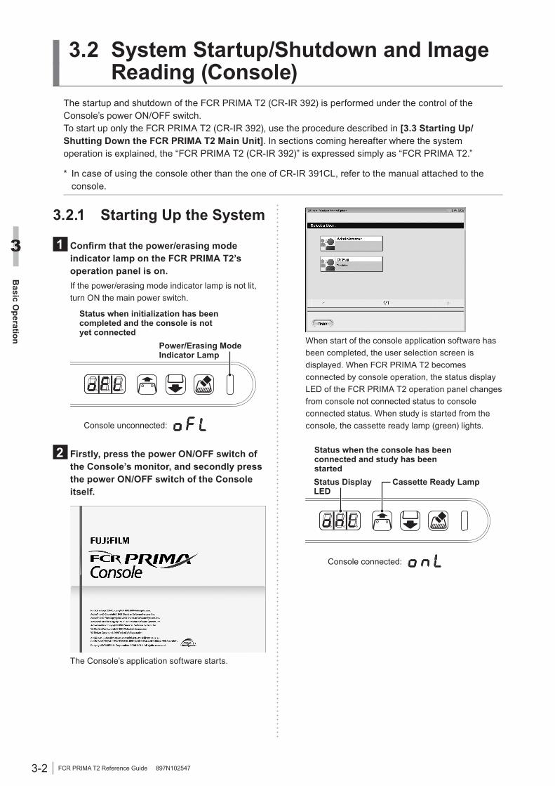
3.2.1 Starting Up the System
1 Confirm that the power/erasing mode indicator lamp on the FCR PRIMA T2’s operation panel is on.If the power/erasing mode indicator lamp is not lit, turn ON the main power switch.
Power/Erasing Mode Indicator Lamp
Console unconnected:
Status when initialization has been completed and the console is not yet connected
2 Firstly, press the power ON/OFF switch of the Console’s monitor, and secondly press the power ON/OFF switch of the Console itself.
The Console’s application software starts.
When start of the console application software has been completed, the user selection screen is displayed. When FCR PRIMA T2 becomes connected by console operation, the status display LED of the FCR PRIMA T2 operation panel changes from console not connected status to console connected status. When study is started from the console, the cassette ready lamp (green) lights.
Console connected:
Status when the console has been connected and study has been started
Cassette Ready LampStatus Display LED
3-3
Basic O
peration
3
FCR PRIMA T2 Reference Guide 897N102547
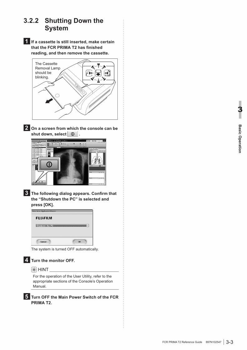
3.2.2 Shutting Down the System
1 If a cassette is still inserted, make certain that the FCR PRIMA T2 has finished reading, and then remove the cassette.
The Cassette Removal Lamp should be blinking.
2 On a screen from which the console can be shut down, select .
3 The following dialog appears. Confirm that the “Shutdown the PC” is selected and press [OK].
The system is turned OFF automatically.
4 Turn the monitor OFF.
HINTFor the operation of the User Utility, refer to the appropriate sections of the Console’s Operation Manual.
5 Turn OFF the Main Power Switch of the FCR PRIMA T2.

3-4
Basic O
peration
3
FCR PRIMA T2 Reference Guide 897N102547
CAUTION
Before using a cassette, ensure that it is applicable to the Image Reader. Using a cassette not applicable to the Image Reader will disable image reading on it.
Before reading a cassette IP image, register patient information and study menus on the Console for the purpose of X-raying the patient.Described herein is the procedure covering steps up to reading exposed images.
1 Input patient information and then select study menus and exposure menus on the Console.For details on how to register patient information and operate study menus on the Console, refer to the appropriate sections of the Console’s Operation Manual.
HINTFor details of available image reading mode, refer to the Operation Manual that describes the User Utility functions of the connected Console.
2 Subject a patient to X-ray exposure.
3 Read the exposed image with the FCR PRIMA T2.
Explained below is the procedure to read IP images of a cassette inserted into the FCR PRIMA T2.1. Confirm that the Cassette Ready Lamp is lit
(green) on the operation panel.
Cassette Ready Lamp
2. Insert a cassette into the equipment in alignment with the guide on the right, with the cassette’s barcode window facing as illustrated below.
The Cassette Ready Lamp should be on.
Cassette guide
Barcode window
Insert straight carefully.
CAUTION● Insert the cassette in the FCR PRIMA
T2 after confirming the sides and the direction of the cassette. Moreover, insert the cassette straight and slowly. If a cassette is inserted incorrectly wrong side or direction, like at a slant, the Image Reader can be damaged.
● When inserting the cassette, be careful not to pinch your finger between the cassette and the cassette set unit.
● Do not turn the scanner cleaning handle during IP processing.
• Remove the exposure marker from the cassette before inserting the cassette in the Image Reader.
• In case of inserting a cassette of other devices, or inserting a cassette in the wrong direction, an error will be occurred.
• Do not shake the Image Reader while reading the image. Such as uneven image, which will prevent image reading, might be generated.
3. Confirm that the Cassette Removal Lamp is blinking (blue) on the operation panel and then remove the cassette.
Cassette Removal Lamp
3.2.3 Reading Cassette IP Images

3-5
Basic O
peration
3
FCR PRIMA T2 Reference Guide 897N102547
When the main power switch is OFF
1 Turn ON the Main Power Switch of the FCR PRIMA T2.
Main Power Switch
Press.
The power/erasing mode indicator lamp lights on the operation panel and the FCR PRIMA T2 starts initialization operation.When the FCR PRIMA T2 is up and running, the cassette ready lamp lights on the operation panel.
Cassette Ready Lamp
See [2.2.3 Operation Panel Display at the Time of Startup/Shutdown] for the operation panel display at the time of FCR PRIMA T2 start.
When the main power switch is ON
1 Press the Stand-by Switch on the operation panel to turn the power ON.
Stand-by Switch
The FCR PRIMA T2 starts initialization operation.When the FCR PRIMA T2 is up and running, the cassette ready lamp lights on the operation panel.
Cassette Ready Lamp
See [2.2.3 Operation Panel Display at the Time of Startup/Shutdown] for the operation panel display at the time of FCR PRIMA T2 start.
3.3 Starting Up/Shutting Down the FCR PRIMA T2 Main Unit
This section explains how to start up/shut down the FCR PRIMA T2 main unit. To operate the Console, use the procedure described in [3.2.1 Starting Up the System].
3.3.1 Starting up the FCR PRIMA T2 main unitCAUTION
An error may occur if you turn on the Main Power Switch of FCR PRIMA T2 right after turning it off. Once turning it off, wait at least 15 seconds before turning it on again.

3-6
Basic O
peration
3
FCR PRIMA T2 Reference Guide 897N102547
3.3.2 Shutting down the FCR PRIMA T2 main unit
1 Press the Stand-by Switch on the operation panel for four seconds.
Stand-by Switch
The status display LED changes from off-line to shutdown processing. When FCR PRIMA T2 shuts down, the status display LED goes out.
See [2.2.3 Operation Panel Display at the Time of Startup/Shutdown] for the operation panel display at the time of FCR PRIMA T2 start.
4-1
Troubleshooting
4
FCR PRIMA T2 Reference Guide 897N102547
Chapter 4 Troubleshooting
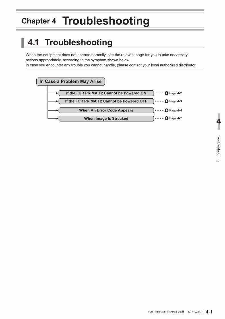
4.1 TroubleshootingWhen the equipment does not operate normally, see the relevant page for you to take necessary actions appropriately, according to the symptom shown below. In case you encounter any trouble you cannot handle, please contact your local authorized distributor.
Page 4-2If the FCR PRIMA T2 Cannot be Powered ON
If the FCR PRIMA T2 Cannot be Powered OFF Page 4-3
When Image Is Streaked Page 4-7
Page 4-4
In Case a Problem May Arise
When An Error Code Appears
4-2
Troubleshooting
4
FCR PRIMA T2 Reference Guide 897N102547
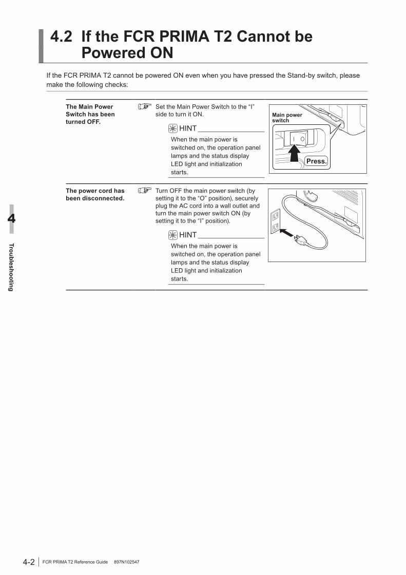
4.2 If the FCR PRIMA T2 Cannot be Powered ON
If the FCR PRIMA T2 cannot be powered ON even when you have pressed the Stand-by switch, please make the following checks:
The Main Power Switch has been turned OFF.
Set the Main Power Switch to the “I” side to turn it ON.
HINTWhen the main power is switched on, the operation panel lamps and the status display LED light and initialization starts.
Main power switch
Press.
The power cord has been disconnected.
Turn OFF the main power switch (by setting it to the “O” position), securely plug the AC cord into a wall outlet and turn the main power switch ON (by setting it to the “I” position).
HINTWhen the main power is switched on, the operation panel lamps and the status display LED light and initialization starts.
4-3
Troubleshooting
4
FCR PRIMA T2 Reference Guide 897N102547
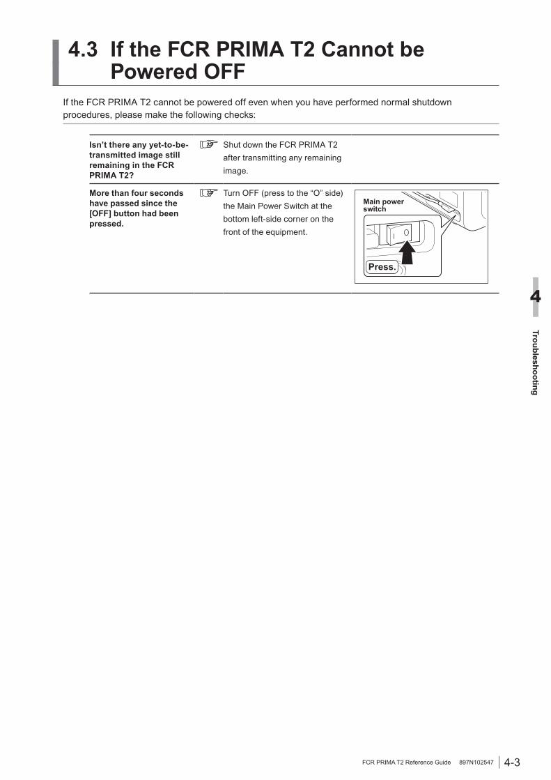
4.3 If the FCR PRIMA T2 Cannot be Powered OFF
If the FCR PRIMA T2 cannot be powered off even when you have performed normal shutdown procedures, please make the following checks:
Isn’t there any yet-to-be-transmitted image still remaining in the FCR PRIMA T2?
Shut down the FCR PRIMA T2 after transmitting any remaining image.
More than four seconds have passed since the [OFF] button had been pressed.
Turn OFF (press to the “O” side) the Main Power Switch at the bottom left-side corner on the front of the equipment.
Main power switch
Press.

4-4
Troubleshooting
4
FCR PRIMA T2 Reference Guide 897N102547
4.4 When An Error Code AppearsThe contents when an error number is flashing on the status display LED of FCR PRIMA T2 and the measures to be taken are shown below. Should you encounter any trouble you cannot handle, contact your local authorized distributor.
■ Status Display LEDWhen an error has occurred or when a condition requiring a warning has occurred, the buzzer sounds and a 3-digit error number flashes on the status display LED shown below. To cancel an error or a warning, press the stand-by switch.
Status Display LED
■ Cancellation of an error or a warning Press the [Power] button to cancel an error or a warning. When the [Power] button is pressed, the flashing display of the status display LED and the buzzer sound stop. The cassette lock also is released and the cassette can be removed.
■ Display of the status display LED and measures to be takenThe display contents of the status display LED and the measures to be taken are shown below.
Error code Title Description Corrective action
Image signal failure Image signal cable connection may be faulty.
Contact your local authorized distributor.
Laser power low The image reading unit’s laser power has come down.
Contact your local authorized distributor.
Read sensitivity low Equipment sensitivity needs to be adjusted.
Contact your local authorized distributor.
High Voltage OFFSince the HV SW for the photomultiplier is faulty, image scanning cannot be performed.
Contact your local authorized distributor.
Cassette insertion error
Cassette may be inserted improperly in terms of position.
After cancellation of an error, take the cassette out first, and then correctly insert it again.
After cancellation of an error, take the cassette out first, and then correctly insert it again.
Cassette unlocking error
Since cassette is improperly inserted in terms of position, lock cannot be undone.
After cancellation of an error, push the cassette toward the far right side.
4-5
Troubleshooting
4
FCR PRIMA T2 Reference Guide 897N102547
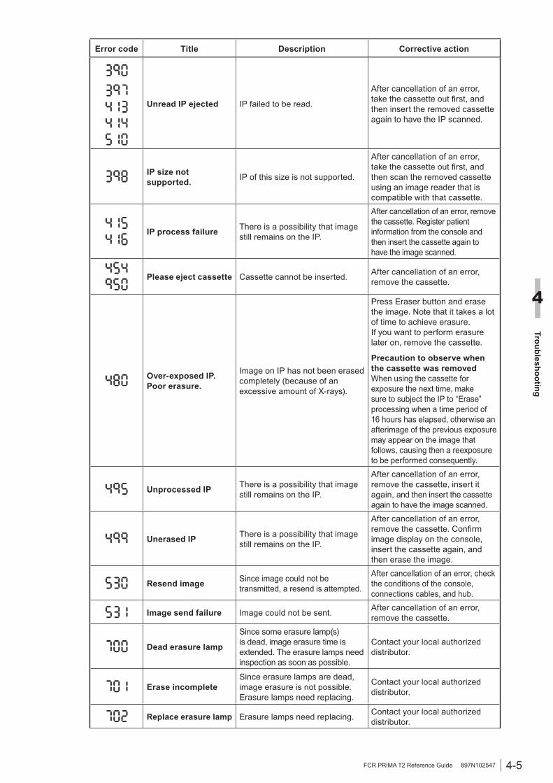
Error code Title Description Corrective action
Unread IP ejected IP failed to be read.
After cancellation of an error, take the cassette out first, and then insert the removed cassette again to have the IP scanned.
IP size not supported. IP of this size is not supported.
After cancellation of an error, take the cassette out first, and then scan the removed cassette using an image reader that is compatible with that cassette.
IP process failure There is a possibility that image still remains on the IP.
After cancellation of an error, remove the cassette. Register patient information from the console and then insert the cassette again to have the image scanned.
Please eject cassette Cassette cannot be inserted. After cancellation of an error, remove the cassette.
Over-exposed IP. Poor erasure.
Image on IP has not been erased completely (because of an excessive amount of X-rays).
Press Eraser button and erase the image. Note that it takes a lot of time to achieve erasure.If you want to perform erasure later on, remove the cassette.
Precaution to observe when the cassette was removedWhen using the cassette for exposure the next time, make sure to subject the IP to “Erase” processing when a time period of 16 hours has elapsed, otherwise an afterimage of the previous exposure may appear on the image that follows, causing then a reexposure to be performed consequently.
Unprocessed IP There is a possibility that image still remains on the IP.
After cancellation of an error, remove the cassette, insert it again, and then insert the cassette again to have the image scanned.
Unerased IP There is a possibility that image still remains on the IP.
After cancellation of an error, remove the cassette. Confirm image display on the console, insert the cassette again, and then erase the image.
Resend image Since image could not be transmitted, a resend is attempted.
After cancellation of an error, check the conditions of the console, connections cables, and hub.
Image send failure Image could not be sent. After cancellation of an error, remove the cassette.
Dead erasure lamp
Since some erasure lamp(s) is dead, image erasure time is extended. The erasure lamps need inspection as soon as possible.
Contact your local authorized distributor.
Erase incompleteSince erasure lamps are dead, image erasure is not possible. Erasure lamps need replacing.
Contact your local authorized distributor.
Replace erasure lamp Erasure lamps need replacing. Contact your local authorized distributor.
4-6
Troubleshooting
4
FCR PRIMA T2 Reference Guide 897N102547
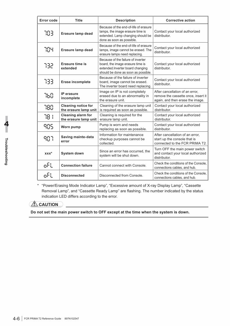
Error code Title Description Corrective action
Erasure lamp dead
Because of the end-of-life of erasure lamps, the image erasure time is extended. Lamp changing should be done as soon as possible.
Contact your local authorized distributor.
Erasure lamp deadBecause of the end-of-life of erasure lamps, image cannot be erased. The erasure lamps need replacing.
Contact your local authorized distributor.
Erasure time is extended
Because of the failure of inverter board, the image erasure time is extended.Inverter board changing should be done as soon as possible.
Contact your local authorized distributor.
Erase incompleteBecause of the failure of inverter board, image cannot be erased. The inverter board need replacing.
Contact your local authorized distributor.
IP erasure incomplete
Image on IP is not completely erased due to an abnormality in the erasure unit.
After cancellation of an error, remove the cassette once, insert it again, and then erase the image.
Cleaning notice for the erasure lamp unit
Cleaning of the erasure lamp unit is required as soon as possible.
Contact your local authorized distributor.
Cleaning alarm for the erasure lamp unit
Cleaning is required for the erasure lamp unit.
Contact your local authorized distributor.
Worn pump Pump is worn and needs replacing as soon as possible.
Contact your local authorized distributor.
Saving mainte-data error
Information for maintenance checkup purposes cannot be collected.
After cancellation of an error, start up the console that is connected to the FCR PRIMA T2.
xxx* System down Since an error has occurred, the system will be shut down.
Turn OFF the main power switch and contact your local authorized distributor.
Connection failure Cannot connect with Console. Check the conditions of the Console, connections cables, and hub.
Disconnected Disconnected from Console. Check the conditions of the Console, connections cables, and hub.
* “Power/Erasing Mode Indicator Lamp”, “Excessive amount of X-ray Display Lamp”, “Cassette Removal Lamp”, and “Cassette Ready Lamp” are flashing. The number indicated by the status indication LED differs according to the error.
CAUTION
Do not set the main power switch to OFF except at the time when the system is down.
4-7
Troubleshooting
4
FCR PRIMA T2 Reference Guide 897N102547
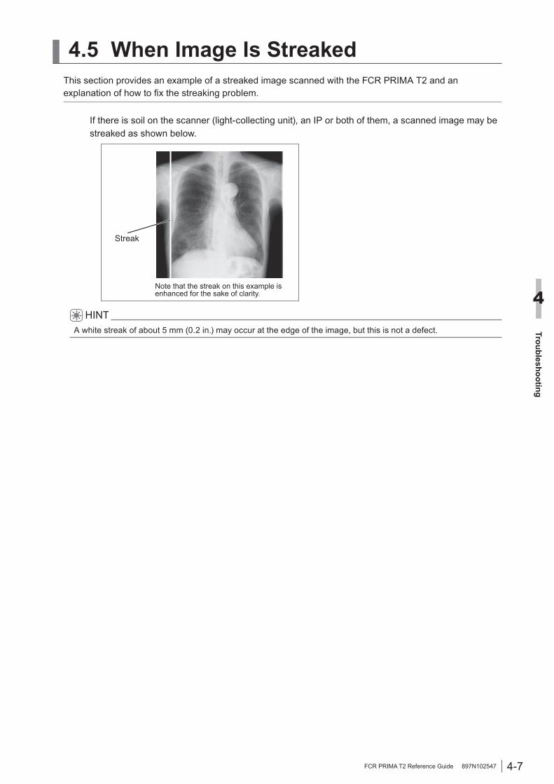
4.5 When Image Is StreakedThis section provides an example of a streaked image scanned with the FCR PRIMA T2 and an explanation of how to fix the streaking problem.
If there is soil on the scanner (light-collecting unit), an IP or both of them, a scanned image may be streaked as shown below.
Streak
Note that the streak on this example is enhanced for the sake of clarity.
HINTA white streak of about 5 mm (0.2 in.) may occur at the edge of the image, but this is not a defect.

4-8
Troubleshooting
4
FCR PRIMA T2 Reference Guide 897N102547
■ Remedial method• Scanner cleaning Perform the cleaning of the scanner turning the scanner cleaning handle in a counterclockwise
direction.
Turn the scannercleaning handle
CAUTION
Please make sure that an image have already been read out before performing the cleaning of the scanner with the FCR PRIMA T2. If you clean the scanner while an image is being read, the image may be incorrectly output.
• Clean the IP. Wipe the surface of the IP with a soft, dry cloth. If the soil fails to come off by dry wiping, wipe the surface using a small amount of dehydrated
ethanol. The IP surface should be completely dried before use.
CAUTION
• Exercise due caution not to damage IPs.• Never use plastic erasers and other solvents.• Do not dig your finger nails into IP surfaces.• Pay due attention not to use a large amount of dehydrated ethanol or clean the IP too
frequently, otherwise the IP edges may turn yellowish.
For IP cleaning, refer to page [B.2 Handling, Daily Care, and Storage of IPs].
5-1
Care and M
aintenance
5
FCR PRIMA T2 Reference Guide 897N102547
Chapter 5 Care and Maintenance
5.1 About Performing Daily Checks and Maintenance
In order to use the FCR PRIMA T2 always in good working order, perform daily checks and maintenance on it.
As for the daily checks, make certain that the FCR PRIMA T2 starts up normally and all equipment that is connected to the FCR PRIMA T2 can communicate normally with the FCR PRIMA T2. For daily care, clean the cassette set unit everyday.
Use the “Users Checksheet” when performing daily checks and maintenance. Enter the following items of information into the “Users Checksheet”:
● Checkups: Enter the date checks were performed.● S value confirmation: Enter the date the S value was checked.● Cassette set unit: Enter the date the cassette set unit was cleaned.

5-2
Care and M
aintenance
5
FCR PRIMA T2 Reference Guide 897N102547
5.2 Cleaning the Cassette Set UnitPerform cleaning, taking care not to let dust into the FCR PRIMA T2.
Wipe the cassette set unit with a dry cloth.
CAUTION
Do not use organic solvents such as thinner, benzine, etc.

5-3
Care and M
aintenance
5
FCR PRIMA T2 Reference Guide 897N102547
5.3 Users Check SheetWe recommend that you periodically check the following so that you can optimally operate the equipment constantly. Make a copy when you are using this check sheet.
● Verification
Details Frequency Date of verification
Does the equipment start up normally? Daily
Is the communication possible normally with the connected equipment?
Daily
Does the S value remain constant?
Every six months
● Cleaning
Unit for cleaning Frequency Date of cleaning
Cassette set unit Every three months

5-4
Care and M
aintenance
5
FCR PRIMA T2 Reference Guide 897N102547
5.4 About Preventive MaintenanceTo maintain safety for the customer, the user, and other people, perform the preventive maintenance mainly involved cleaning of the parts and replacing of consumables. For the preventive maintenance, consult our official dealer or local representative.The timing of performing preventive maintenance or the replacement cycle of periodic replacement parts differs depending on cassette usage and running time of this equipment per day. The preventive maintenance of machine performed by the specified dealer differs depending on the contents of contract.
■ Timing of the Preventive MaintenanceThe timing of the preventive maintenance are shown below.• One year or when a process count of about 6,000 is reached• Two years or when a process count of about 12,000 is reached• Three years or when a process count of about 18,000 is reached• Four years when a process count of about 24,000 is reached• Five years when a process count of about 30,000 is reached
■ Preventive maintenance to be performed when the machine has been used for one year or when a process count of about 6,000 is reachedPerform the preventive maintenance shown below.Cleaning of the parts• Reflection plate, and filter of the erasure unit• Covers, shutter
Checking the Machine• Erasure lamp lighting time• Protective grounding• Image/conveyance• S value• Error log
■ Preventive maintenance to be performed when the machine has been used for two years or when a process count of about 12,000 is reachedPerform the preventive maintenance shown below.Cleaning of the parts• Suction cups, rubber rollers• Reflection plate, and filter of the erasure unit• Light-collecting guide• Covers, shutter
Checking the Machine• Erasure lamp lighting time• Protective grounding• Image/conveyance• S value• Error log

5-5
Care and M
aintenance
5
FCR PRIMA T2 Reference Guide 897N102547
■ Preventive maintenance to be performed when the machine has been used for three years or when a process count of about 18,000 is reachedPerform the preventive maintenance shown below.Cleaning of the parts• Reflection plate, and filter of the erasure unit• Covers, shutter
Checking the Machine• Erasure lamp lighting time• Protective grounding• Image/conveyance• S value• Error log
■ Preventive maintenance to be performed when the machine has been used for four years or when a process count of about 24,000 is reachedPerform the preventive maintenance shown below.Cleaning of the parts• Suction cups, rubber rollers• Reflection plate, and filter of the erasure unit• Light-collecting guide• Covers, shutter
Checking the Machine• Erasure lamp lighting time• Protective grounding• Image/conveyance• S value• Error log
■ Preventive maintenance to be performed when the machine has been used for five years or when a process count of about 30,000 is reachedPerform the preventive maintenance shown below.Cleaning of the parts• Reflection plate, and filter of the erasure unit• Covers, shutter
Checking the Machine• Erasure lamp lighting time• Protective grounding• Image/conveyance• S value• Error log

5-6
Care and M
aintenance
5
FCR PRIMA T2 Reference Guide 897N102547
A-1
Appendix A
Specifications
FCR PRIMA T2 Reference Guide 897N102547
Appendix A Specifications
A.1 SpecificationsA.1.1 Details of Equipment Specifications
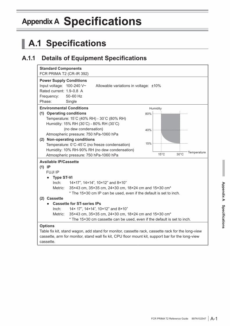
Standard ComponentsFCR PRIMA T2 (CR-IR 392)
Power Supply ConditionsInput voltage: 100-240 V~ Allowable variations in voltage: ±10%Rated current: 1.9-0.8 AFrequency: 50-60 HzPhase: Single
Environmental Conditions(1) Operating conditions Temperature: 15˚C (40% RH) - 30˚C (80% RH) Humidity: 15% RH (30˚C) - 80% RH (30˚C) (no dew condensation) Atmospheric pressure: 750 hPa-1060 hPa(2) Non-operating conditions Temperature: 0˚C-45˚C (no freeze condensation) Humidity: 10% RH-90% RH (no dew condensation) Atmospheric pressure: 750 hPa-1060 hPa
80%
40%
15%
15°C 30°C
Humidity
Temperature
Available IP/Cassette(1) IP FUJI IP ● Type ST-VI Inch: 14×17”, 14×14”, 10×12” and 8×10” Metric: 35×43 cm, 35×35 cm, 24×30 cm, 18×24 cm and 15×30 cm* * The 15×30 cm IP can be used, even if the default is set to inch. (2) Cassette ● Cassette for ST-series IPs Inch: 14× 17”, 14×14”, 10×12” and 8×10” Metric: 35×43 cm, 35×35 cm, 24×30 cm, 18×24 cm and 15×30 cm* * The 15×30 cm cassette can be used, even if the default is set to inch.
OptionsTable fix kit, stand wagon, add stand for monitor, cassette rack, cassette rack for the long-view cassette, arm for monitor, stand wall fix kit, CPU floor mount kit, support bar for the long-view cassette.
A-2
Appendix A
Specifications
FCR PRIMA T2 Reference Guide 897N102547
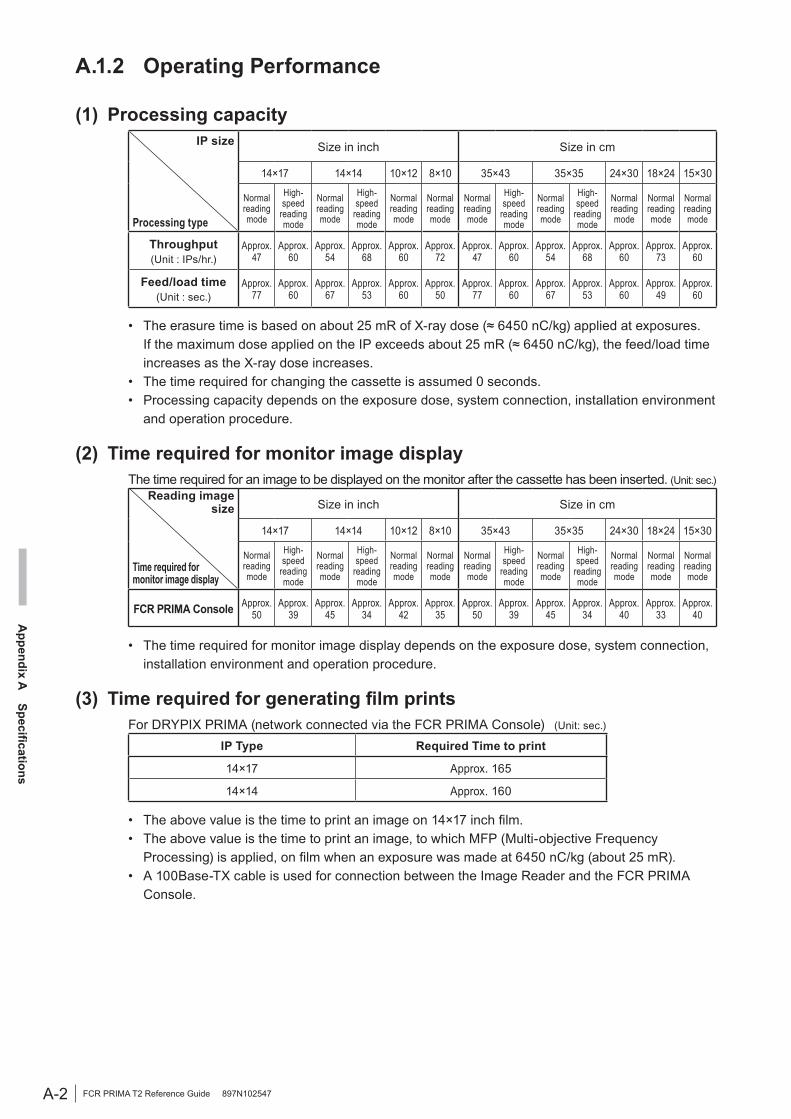
A.1.2 Operating Performance
(1) Processing capacityIP size
Processing type
Size in inch Size in cm
14×17 14×14 10×12 8×10 35×43 35×35 24×30 18×24 15×30
Normal reading mode
High-speed
reading mode
Normal reading mode
High-speed
reading mode
Normal reading mode
Normal reading mode
Normal reading mode
High-speed
reading mode
Normal reading mode
High-speed
reading mode
Normal reading mode
Normal reading mode
Normal reading mode
Throughput (Unit : IPs/hr.)
Approx.47
Approx.60
Approx.54
Approx.68
Approx.60
Approx.72
Approx.47
Approx.60
Approx.54
Approx.68
Approx.60
Approx.73
Approx.60
Feed/load time (Unit : sec.)
Approx.77
Approx.60
Approx.67
Approx.53
Approx.60
Approx.50
Approx.77
Approx.60
Approx.67
Approx.53
Approx.60
Approx.49
Approx.60
• The erasure time is based on about 25 mR of X-ray dose (≈ 6450 nC/kg) applied at exposures. If the maximum dose applied on the IP exceeds about 25 mR (≈ 6450 nC/kg), the feed/load time increases as the X-ray dose increases.
• The time required for changing the cassette is assumed 0 seconds.• Processing capacity depends on the exposure dose, system connection, installation environment
and operation procedure.
(2) Time required for monitor image displayThe time required for an image to be displayed on the monitor after the cassette has been inserted. (Unit: sec.)
Reading image size
Time required for monitor image display
Size in inch Size in cm
14×17 14×14 10×12 8×10 35×43 35×35 24×30 18×24 15×30
Normal reading mode
High-speed
reading mode
Normal reading mode
High-speed
reading mode
Normal reading mode
Normal reading mode
Normal reading mode
High-speed
reading mode
Normal reading mode
High-speed
reading mode
Normal reading mode
Normal reading mode
Normal reading mode
FCR PRIMA Console Approx.50
Approx.39
Approx.45
Approx.34
Approx.42
Approx.35
Approx.50
Approx.39
Approx.45
Approx.34
Approx.40
Approx.33
Approx.40
• The time required for monitor image display depends on the exposure dose, system connection, installation environment and operation procedure.
(3) Time required for generating film printsFor DRYPIX PRIMA (network connected via the FCR PRIMA Console) (Unit: sec.)
IP Type Required Time to print
14×17 Approx. 165
14×14 Approx. 160
• The above value is the time to print an image on 14×17 inch film.• The above value is the time to print an image, to which MFP (Multi-objective Frequency
Processing) is applied, on film when an exposure was made at 6450 nC/kg (about 25 mR).• A 100Base-TX cable is used for connection between the Image Reader and the FCR PRIMA
Console.

A-3
Appendix A
Specifications
FCR PRIMA T2 Reference Guide 897N102547
A.1.3 Applicable Safety StandardNumber/year of the standard Title
EN 60601-1:1990/A1:1993IEC 60601-1:1988/A2:1995
Medical electrical equipment — Part 1: General Requirement for safety
EN 60601-1-1:2001IEC 60601-1-1:2000
Medical electrical equipment — Part 1: General requirements for safety — Collateral standards : Safety requirements for medical electrical systems
EN 60601-1-2:2001+Amd1:2006IEC 60601-1-2:2001+Amd1:2004
Medical electrical equipment — Part 1-2: General requirements for safety — Collateral standard: Electromagnetic compatibility — Requirements and tests
IEC 60825-1:2007 Safety of laser products — Part 1: Equipment classification, requirements and user’s guide
A-4
Appendix A
Specifications
FCR PRIMA T2 Reference Guide 897N102547
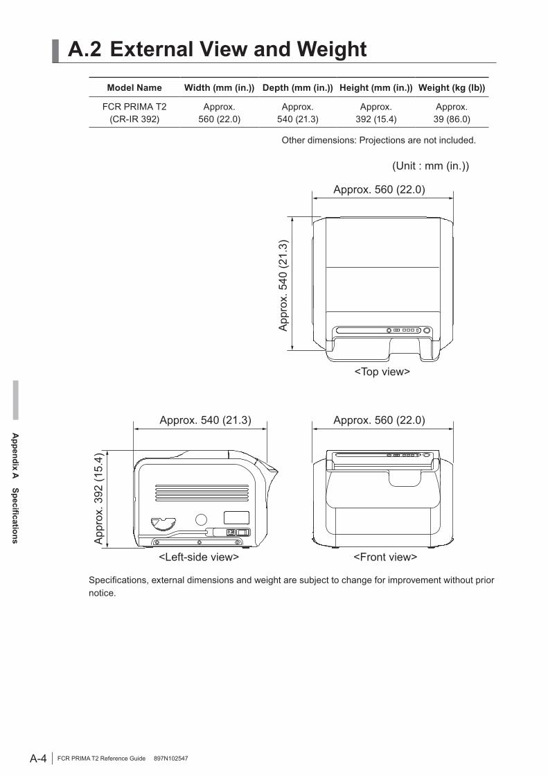
A.2 External View and Weight
Model Name Width (mm (in.)) Depth (mm (in.)) Height (mm (in.)) Weight (kg (lb))
FCR PRIMA T2(CR-IR 392)
Approx. 560 (22.0)
Approx. 540 (21.3)
Approx.392 (15.4)
Approx. 39 (86.0)
Other dimensions: Projections are not included.
App
rox.
392
(15.
4)
(Unit : mm (in.))
<Top view>
<Front view><Left-side view>
Approx. 560 (22.0)
Approx. 560 (22.0)Approx. 540 (21.3)
App
rox.
540
(21.
3)
Specifications, external dimensions and weight are subject to change for improvement without prior notice.
B-1
Appendix B
IP H
andling
FCR PRIMA T2 Reference Guide 897N102547
Erasure
If an IP that is going to be used for radiographing work has not been used yet on the day, it is necessary to perform erasure on that IP.The objective of the erasure is to dissipate any excess energy the IP has accumulated in preparation for radiographic exposure. Even when the IP is stored in a room, it absorbs and accumulates natural radiation such as cosmic rays and radiation energy emanating from radioisotopes contained in construction materials such as those used for floors and walls. If such an energy-loaded IP is used as-is, image degradation may result.Over-exposed and incorrectly exposed IPs should always be subjected to erasure processing before use.
Appendix B IP Handling
B.1 IP Image Erasure OperationIn the event of a failed exposure or when an IP is going to be used for the first time on a given day, it is necessary to erase any image remaining on the IP before use. To erase images, perform erasure.
For details of image erasure, see [3.1 Performing Erasure Before Use IPs].
B-2
Appendix B
IP H
andling
FCR PRIMA T2 Reference Guide 897N102547
B.2 Handling, Daily Care, and Storage of IPsThis section provides descriptions of important notes about the storage and daily handling of IPs and methods by which to clean them.
Storage conditions
• Store IPs under the following environmental conditions:
Unopened: 35°C max. Opened: 33°C max., 80% RH• IPs should be stored out of direct sunlight,
ultraviolet rays, and various kinds of radiation.
• Do not bend or fold IPs, and do not apply strong force to them.
Everyday handling
• Do not use an IP bearing a flaw(s) which can interfere with diagnostic assessment.
• Handle IPs as gently and carefully as possible, taking care not to scratch and soil them.
• Do not bend IPs in small radii. Do not bump them against other objects. Do not drop them onto the floor or the top of a table.
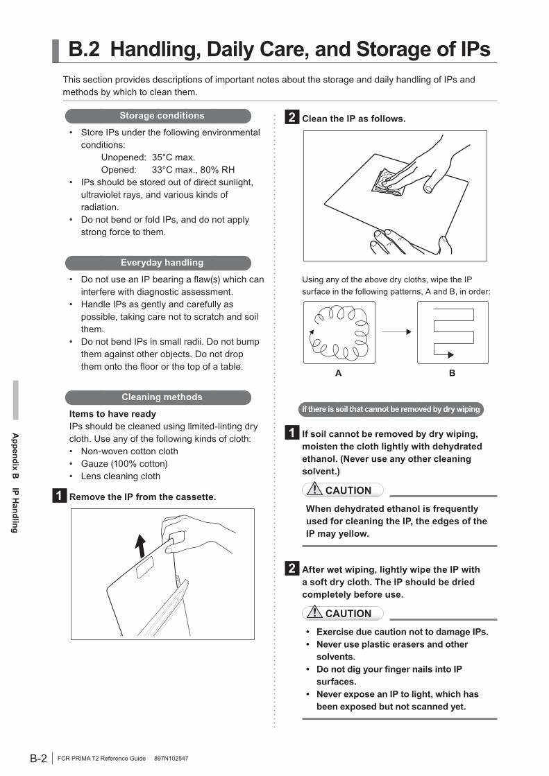
Cleaning methods
Items to have readyIPs should be cleaned using limited-linting dry cloth. Use any of the following kinds of cloth:• Non-woven cotton cloth• Gauze (100% cotton)• Lens cleaning cloth
1 Remove the IP from the cassette.
2 Clean the IP as follows.
Using any of the above dry cloths, wipe the IP surface in the following patterns, A and B, in order:
A B
If there is soil that cannot be removed by dry wiping
1 If soil cannot be removed by dry wiping, moisten the cloth lightly with dehydrated ethanol. (Never use any other cleaning solvent.)
CAUTION
When dehydrated ethanol is frequently used for cleaning the IP, the edges of the IP may yellow.
2 After wet wiping, lightly wipe the IP with a soft dry cloth. The IP should be dried completely before use.
CAUTION
• Exercise due caution not to damage IPs.• Never use plastic erasers and other
solvents.• Do not dig your finger nails into IP
surfaces.• Never expose an IP to light, which has
been exposed but not scanned yet.

C-1
Appendix C
Text Inform
ation Printed on Film
FCR PRIMA T2 Reference Guide 897N102547
Appendix C Text Information Printed on Film
C.1 Text Information Printed on FilmThis section provides a description of information to be printed on film.
In the case of the two-image formatShown below are an example of annotation printing in the two-image format and the meanings of the on-film annotations.
FUJI HOSPITAL 04001676 A 0000 A 020
(1) Hospital name(2) IP No.(3) EDR mode + menu code(4) System ID + image No.
[M] 23SCALE: 50% RT-04
G 1.0G#0.9+0.30 R 5T0.31. D 2MO.2
L 2.0 S 187 C *1.0*1.0 AP
G 1.1G#0.9+0.30 R 5TO.3 D 2MO.2SKULL, GENERAL 0000000001 John Smith
1992. 11. 27 [17:43]
R->L
(5) FCR image processing conditions
(9) Patient ID(10) Patient name
(11) Date of exposure(12) Time of exposure
(13) Film mark(14) Sex(15) Age or Date of birth
(6) Exposure menu name(7) Standardization conditions + correction item
(8) Image reversal mark
(16) Reduction ratio(17) Set processing information
Item Description(1) Hospital name The name of the hospital where the exposure was made is displayed.(2) IP No. The barcode No. of the IP is displayed.
(3) EDR mode + menu code The EDR mode and the menu code are displayed.(* In the Standard Film Annotation, only the menu code is displayed.)
(4) System ID + image No.
System ID: An image reader-specific ID code which is one of the characters A to Z and is displayed in reverse video.
Image No.: A 3-digit consecutive ordinal number at which the image was scanned on the day is displayed.
(5) FCR image processing conditions Exposure menu-specific exposure conditions are displayed.(6) Exposure menu name The name of the menu under which the exposure was made is displayed.
(7) Standardization conditions + correction item
Latitude (L) and sensitivity (S) value data are displayed along with correction information (C).
(8) Image reversal mark Displayed when the image is reversed.(9) Patient ID The ID of the patient exposed is displayed.(10) Patient name The name of the patient exposed is displayed.(11) Date of exposure The date the exposure was made is displayed.(12) Time of exposure The time of the day when the IP was registered is displayed.(13) Film mark The orientation in which the exposure was made is displayed.(14) Sex The sex of the patient exposed is displayed.
(15) Age or Date of birth The age of the patient when the exposure was made or his/her birth date is displayed.
(16) Reduction ratio The image’s reduction ratio, from the life size on down, is displayed.(17) Set processing information The image’s batch processing information is displayed.
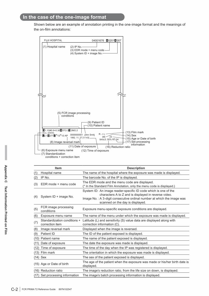
C-2
Appendix C
Text Inform
ation Printed on Film
FCR PRIMA T2 Reference Guide 897N102547
In the case of the one-image formatShown below are an example of annotation printing in the one-image format and the meanings of the on-film annotations:
FUJI HOSPITAL
SKULL, GENERAL
[M] 23SKALE: 50% RT-04
R - > L1992. 11. 27 [17:43]0000000001 John Smitj
G 1.1G#0.9+0.30 A 5TO.3 D 2MO.2
L 2.1 S 277 C *1.0*1.0 AP
04001676 A 0201 A 007
(1) Hospital name (2) IP No.(3) EDR mode + menu code(4) System ID + image No.
(5) FCR image processing conditions
(9) Patient ID(10) Patient name
(11) Date of exposure(12) Time of exposure
(13) Film mark(14) Sex(15) Age or Date of birth(17) Set processing information
(6) Exposure menu name(7) Standardization conditions + correction item
(8) Image reversal mark
(16) Reduction ratio
Item Description(1) Hospital name The name of the hospital where the exposure was made is displayed.(2) IP No. The barcode No. of the IP is displayed.
(3) EDR mode + menu code The EDR mode and the menu code are displayed.(* In the Standard Film Annotation, only the menu code is displayed.)
(4) System ID + image No.
System ID: An image reader-specific ID code which is one of the characters A to Z and is displayed in reverse video.
Image No. : A 3-digit consecutive ordinal number at which the image was scanned on the day is displayed.
(5) FCR image processing conditions Exposure menu-specific exposure conditions are displayed.
(6) Exposure menu name The name of the menu under which the exposure was made is displayed.
(7) Standardization conditions + correction item
Latitude (L) and sensitivity (S) value data are displayed along with correction information (C).
(8) Image reversal mark Displayed when the image is reversed.(9) Patient ID The ID of the patient exposed is displayed.(10) Patient name The name of the patient exposed is displayed.(11) Date of exposure The date the exposure was made is displayed.(12) Time of exposure The time of the day when the IP was registered is displayed.(13) Film mark The orientation in which the exposure was made is displayed.(14) Sex The sex of the patient exposed is displayed.
(15) Age or Date of birth The age of the patient when the exposure was made or his/her birth date is displayed.
(16) Reduction ratio The image’s reduction ratio, from the life size on down, is displayed.(17) Set processing information The image’s batch processing information is displayed.

Z-1
Appendix Z
Precautions for Exposure
FCR PRIMA T2 Reference Guide 897N102547
Z.1.1 Using the Bucky’s Device
It is recommended to use Bucky’s device to remove scatter rays and obtain a high-quality image. When carrying out exposure using a stationary grid, it is recommended to use a 60 lines/cm grid with fewer artifacts. Use a grid whose line direction is parallel to the cassette’s vertical direction (between top and bottom).
Top
Bottom
Green mark
Cassette
Z.1.2 Precautions to Observe Before Using an IP
(1) IP erasure processingBefore using an IP, ensure that the IP has been subjected to image erasure processing. Particularly when performing a low-dose exposure (high-sensitivity exposure), be sure to use an IP that has been subjected to erasure processing.Though in rare cases, remaining images may appear on an IP from which images have already been read out, if such IP is used for re-reading with no due image erasure processing. Subject IPs to proper image erasure processing and avoid the use of insufficiently erased IPs.
(2) “Over-exposed IP. Poor erasure.”If the “Over-exposed IP. Poor erasure.” error code is displayed for an IP exposed to a large X-ray dose shown below, which is then read on the Image Reader, you press Eraser button.If the IP removed from the Image Reader is to be subjected to erasure processing later, wait at least for 16 hours and then perform erasure processing.
<Exposure at large X-ray dose>ST-VI : Tungsten (or W) target, about 400 mR
or more
Subjecting an IP to exposure continuously at large X-ray dose may cause damage due to X-rays (sensitivity deterioration) to occur on the IP. For this reason, avoid using the same IP for exposure at large X-ray dose repeatedly.
Appendix Z Precautions for Exposure
Z.1 Precautions to Take Before ExposureThis section describes precautions to observe before performing exposure.

Z-2
Appendix Z
Precautions for Exposure
FCR PRIMA T2 Reference Guide 897N102547
Z.2.1 Precautions for Exposure in the AUTO MODE
In the Auto mode, radiographic images that interfere with image reading are obtained in some cases due to variations in multileaf collimator settings on the X-ray exposure unit and/or the effects of scatter rays. If you encounter such cases, please contact your local authorized distributor for consultation and advice, and make radiographic exposures in a different mode such as the Semi-auto mode or the Fix mode.
Here are precautions to take in order to obtain stable image quality in the Auto mode:1. Radiation Field and IP Split Pattern
Recognition .............................................. (1)2. Depiction of the Cervical Region ............. (2)3. Depiction of HIP JOINT AXL - 2 .............. (3)4. Cautions for “PANTOMO” X-ray
Exposures Using a 10”×12” Cassette ...... (4)5. EDR Image Data Analysis .............................(5)
(1) Radiation Field and IP Split Pattern Recognition• Be sure that the center (25×25 mm (1.0×1.0
in.)) of the IP is in the radiation field. If the IP is split for multiple exposures, each center of the split portions must be covered by the radiation field.
IP center: 25 mm × 25 mm (1.0×1.0 in.) area (black rectangles in examples above) located in the center of the IP
Center of the split portion: 25 mm × 25 mm (1.0×1.0 in.) area (black rectangles in examples above) located in the center of each split portion.
• Do not set the radiation field extremely small. Be sure to expose X-rays on one thirds or more of the length of each side of the IP.
• Be sure that each side of the radiation field does not overlap with the contrast medium. Error will occur if they overlap each other.
This subsection explains precautions to be exercised regarding “Radiation Field and IP Split Pattern Recognition” processing (hereafter referred to as PRIEF) which is performed when you make radiographic exposures in the Auto mode.The “S” in PRIEF4S and PRIEF1S is a symbol to signify that IP-split recognition is possible. There are the following four split-IP exposure patterns:
Full-IP exposure Half-split IP (vertical) Quarter-split IPHalf-split IP (horizontal)
* When making multiple exposures on a split IP, a split portion(s) may be left unexposed.
Guidance as to which to use: PRIEF4S or PRIEF1S Table Z-1 shows the relationships among anatomical regions to be radiographed, radiographic exposure methods, PRIEF4S and PRIEF1S. Explanations on PRIEF4S and PRIEF1S are also provided along with precautions to take with them.
[Table. Z-1] At-a-glance guide to availability of PRIEF4S/PRIEF1S for each anatomical region/exposure method
Plain Contrast Medium Tomography
Head 4S 4S 4S(1 for pantomography)
Neck 4S 4S 1S
Chest 4S 4S(1 for esophagus) 1
Abdomen 4S4S
(1S for stomach and intestines)
1
Pelvis 4S 4S 1Upper
extremity 4S 4S 1
Lower extremity 4S 4S 1
Z.2 Precautions to Take in Each ModeThis section describes some precautions that must be followed when making radiographic exposures in each of the following modes: Auto mode, Semi-auto mode, Semi-X mode, and Fix Mode.
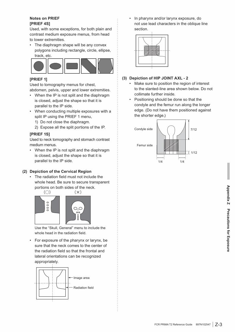
Z-3
Appendix Z
Precautions for Exposure
FCR PRIMA T2 Reference Guide 897N102547
Notes on PRIEF[PRIEF 4S]Used, with some exceptions, for both plain and contrast medium exposure menus, from head to lower extremities.• The diaphragm shape will be any convex
polygons including rectangle, circle, ellipse, track, etc.
[PRIEF 1]Used to tomography menus for chest, abdomen, pelvis, upper and lower extremities.• When the IP is not split and the diaphragm
is closed, adjust the shape so that it is parallel to the IP side.
• When conducting multiple exposures with a split IP using the PRIEF 1 menu,
1) Do not close the diaphragm. 2) Expose all the split portions of the IP.
[PRIEF 1S]Used to neck tomography and stomach contrast medium menus.• When the IP is not split and the diaphragm
is closed, adjust the shape so that it is parallel to the IP side.
(2) Depiction of the Cervical Region• The radiation field must not include the
whole head. Be sure to secure transparent portions on both sides of the neck.
Use the “Skull, General” menu to include the whole head in the radiation field.
• For exposure of the pharynx or larynx, be sure that the neck comes to the center of the radiation field so that the frontal and lateral orientations can be recognized appropriately.
Image area
Radiation field
• In pharynx and/or larynx exposure, do not use lead characters in the oblique line section.
(3) Depiction of HIP JOINT AXL - 2• Make sure to position the region of interest
to the slanted-line area shown below. Do not collimate further inside.
• Positioning should be done so that the condyle and the femur run along the longer edge. (Do not have them positioned against the shorter edge.)
7/12
1/12
1/41/4
Condyle side
Femur side

Z-4
Appendix Z
Precautions for Exposure
FCR PRIMA T2 Reference Guide 897N102547
(4) Cautions for “PANTOMO” X-ray Exposures Using a 10”×12” Cassette• To obtain properly displayed images, set the
10”×12” cassette in the dedicated cassette holder of the exposure unit so that the green mark on top of the cassette is positioned on the right side when viewed from the X-ray tube, as illustrated below.
10"x12" cassette
Green mark
Right side
• For image output, the “PANTOMO” X-ray exposure menu (M2004) takes only an area of 15×30cm from the 10”×12” exposure area. If you wish an image be output using the entire 10”×12” area, use the “PANTOMO-2:T” (7004) exposure menu.
(5) EDR Image Data Analysis• Image unevenness appearing when the grid
used for exposure is not correctly positioned in terms of the bulb, clothes shadow or unevenly radiated X-ray to the X-ray exposure area can be referred to as the problems occurring during the EDR image data analysis, which cause unstable density on the image. Avoid such unevenness in the X-ray exposure area as far as possible.
• If the target includes such materials as gypsum, denture, etc., stable density may not be obtained because such materials make it difficult to analyze EDR image data. In such a case, use the S-Shift/C-Shift or FIX MODE.
• For multiple exposures with a split IP, make exposure doses on each portion of the IP as equal as possible (maximum 1.6 times). In other words, for multiple exposures, submit each portion of the IP to the appropriate exposure dose according to the intended anatomical region as usual.
Precautions when using the AUTO MODE.Mode type Precautions
I
As this mode is available on the assumption that it extracts information concerning the skin, secure the positioning so that there is an area other than the target where the direct X-rays are incident.
II No special precautions.
III Be sure to use the Ba contrast medium.
IV
1. Be sure to secure the positioning so that the X-rays are incident directly in the area outside the target.
2. As the reading latitude is fixed, it is necessary to control the tube voltage as usual according to the thickness of the target.
V
As the reading latitude is fixed, it is necessary to control the tube voltage as usual according to the thickness of the target.
VI No special precautions.VII No special precautions.
Z.2.2 Precautions for Exposure in the SEMI-AUTO MODE
The precautions are common to Semi I, II, III or III(**).• Center area of the IP 10 × 10 cm (3.9 × 3.9 in.) (Semi I) 7 × 7 cm (2.8 × 2.8 in.) (Semi II) 5 × 5 cm (2.0 × 2.0 in.) (Semi III) Position the portion you need to display of
ten in each of the 5×5 cm (2.0×2.0 in.) (Semi III (**)) center are as of the half-split IPs (both upper and lower halves and right and left halves) and the quarter-split IP.
• Never position anything other than the subject in the above mentioned areas. If anything other than the subject is positioned in such areas, the image density will become thinner. In addition, do not position any metals or artificial bones in such areas. The image density will become higher if such an object is positioned in such areas.
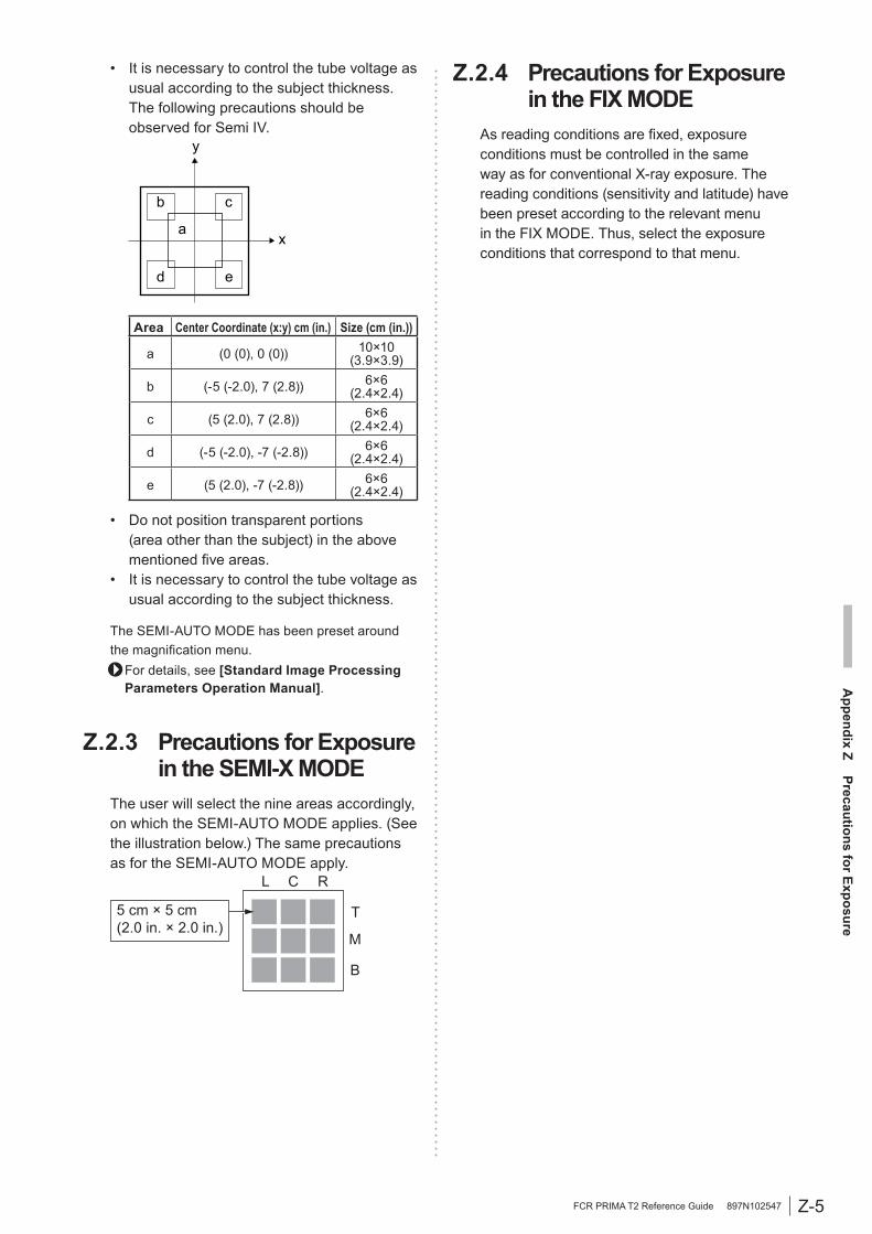
Z-5
Appendix Z
Precautions for Exposure
FCR PRIMA T2 Reference Guide 897N102547
• It is necessary to control the tube voltage as usual according to the subject thickness. The following precautions should be observed for Semi IV.
a
b
d e
y
x
c
Area Center Coordinate (x:y) cm (in.) Size (cm (in.))
a (0 (0), 0 (0)) 10×10(3.9×3.9)
b (-5 (-2.0), 7 (2.8)) 6×6(2.4×2.4)
c (5 (2.0), 7 (2.8)) 6×6(2.4×2.4)
d (-5 (-2.0), -7 (-2.8)) 6×6(2.4×2.4)
e (5 (2.0), -7 (-2.8)) 6×6(2.4×2.4)
• Do not position transparent portions (area other than the subject) in the above mentioned five areas.
• It is necessary to control the tube voltage as usual according to the subject thickness.
The SEMI-AUTO MODE has been preset around the magnification menu.
For details, see [Standard Image Processing Parameters Operation Manual].
Z.2.3 Precautions for Exposure in the SEMI-X MODE
The user will select the nine areas accordingly, on which the SEMI-AUTO MODE applies. (See the illustration below.) The same precautions as for the SEMI-AUTO MODE apply.
L C R
T
M
B
5 cm × 5 cm(2.0 in. × 2.0 in.)
Z.2.4 Precautions for Exposure in the FIX MODE
As reading conditions are fixed, exposure conditions must be controlled in the same way as for conventional X-ray exposure. The reading conditions (sensitivity and latitude) have been preset according to the relevant menu in the FIX MODE. Thus, select the exposure conditions that correspond to that menu.
Z-6
Appendix Z
Precautions for Exposure
FCR PRIMA T2 Reference Guide 897N102547
• When you are changing image processing parameters, check adequately that such a change does not affect image reading adversely. To change standard image processing parameter settings, verify results of the changed settings on multiple images through consultation with the image reading physician, and then perform exposure.
• When performing exposure of an anatomical region which is hard to distinguish difference between the right side and the left side, take proper measures by, for example, placing lead characters so that the front and the back of an image is identified clearly.
Z.3 Other PrecautionsShown below are other precautions to observe when performing exposure.

Maintenance and Inspection
FCR PRIMA T2 Reference Guide 897N102547
Maintenance and Inspection
1 Maintenance and Inspection Items Assigned to Specified DealerFor periodical inspection of the equipment and necessary arrangements, consult our official dealer or local representative.

Maintenance and Inspection
FCR PRIMA T2 Reference Guide 897N102547
Index
FCR PRIMA T2 Reference Guide 897N102547
IndexB
Buzzer ................................................ 2-4, 4-4
CCassette ............................................. 3-4, A-1Cassette Ready Lamp ................. 2-4, 2-5, 3-4Cassette Removal Lamp ..................... 2-4, 2-5Cassette Set Unit ....................................... 2-3Check sheet ............................................... 5-3Cleaning methods of IPs ........................... B-2Cleaning the cassette set unit .................... 5-2
EEraser Button ...................................... 2-4, 3-1Erasure ................................................ 3-1, B-1Error Code .................................................. 4-4Everyday handling of IPs ........................... B-2Excessive amount of X-ray Display Lamp ............................. 2-4, 2-5External Device Connector ........................ 2-3External dimensions .................................. A-4
FFCR PRIMA T2 .......................................... 2-1
IImaging plate ....................................... 2-1, A-1Information to be printed on film ................ C-1IP ......................................................... 2-1, A-1
MMain Power Switch ............................. 2-3, 3-5
OOperation Panel .................................. 2-3, 2-4Operation Panel Display ............................ 2-5Over-exposed and incorrectly exposed IPs................................................ B-1
PPower/Erasing Mode Indicator Lamp ... 2-4, 2-5Power Inlet ................................................. 2-3Preventive Maintenance ............................. 5-4
SScanner cleaning ....................................... 4-8Scanner Cleaning Handle .................. 2-3, 4-8Shutting down the system .......................... 3-3Stand-by Switch ........... 2-4, 2-5, 3-5, 3-6, 4-4Starting up the system ............................... 3-2Status Display LED ..................... 2-4, 2-5, 4-4Storage conditions .................................... B-2System configuration .................................. 2-2
UUsing the Bucky’s device ........................... Z-1
WWeight ....................................................... A-4