Reference Architecture for VMware vSphere 4 in a...
33
Reference Architecture for VMware vSphere 4 in a 10 Gigabit iSCSI Environment with Dell PowerEdge™ Blade Servers Business Ready Configuration for Dell Blade Servers and EqualLogic Storage March 2010 Dell Virtualization Solutions Engineering http://www.dell.com/virtualization/businessready
Transcript of Reference Architecture for VMware vSphere 4 in a...

Reference Architecture for VMware vSphere 4 in a 10 Gigabit iSCSI Environment with Dell PowerEdge™ Blade Servers
Business Ready Configuration for Dell Blade Servers and EqualLogic Storage
March 2010
Dell Virtualization Solutions Engineering
http://www.dell.com/virtualization/businessready
Reference Architecture for VMware vSphere 4 in a 10 Gigabit iSCSI Environment
Dell Inc 2
Information in this document is subject to change without notice.
© Copyright 2010 Dell Inc. All rights reserved.
Reproduction in any manner whatsoever without the written permission of Dell Inc. is strictly
forbidden.
This white paper is for informational purposes only and may contain typographical errors or technical
inaccuracies. The content is provided as is, without express or implied warranties of any kind.
Dell, the DELL logo, EqualLogic, PowerEdge, PowerConnect, and Dell OpenManage are trademarks of
Dell Inc. Microsoft is a registered trademark of Microsoft Corporation; VMware, vSphere, vCenter, and
VMotion are registered trademarks or trademarks (the "Marks") of VMware, Inc. in the United States
and/or other jurisdictions. Other trademarks and trade names may be used in this document to refer
to either the entities claiming the marks and names or their products. Dell disclaims proprietary
interest in the marks and names of others.

Reference Architecture for VMware vSphere 4 in a 10 Gigabit iSCSI Environment
Dell Inc 3
Table of Contents 1 Introduction 5
2 Audience and Scope 5
3 Overview 5
3.1 VMware vSphere 4 6
3.2 Dell PowerEdge Blade Servers 7
3.3 Dell EqualLogic PS6010 Series iSCSI Arrays 8
4 Specification 9
5 Reference Architecture 12
6 Network Architecture 13
6.1 Understanding the Dell Blade Network Architecture 13
6.2 vSphere Network Overview 14
6.3 LAN Architecture 15
6.4 iSCSI SAN Architecture 19
7 Scalability 23
7.1 Scaling Compute Resources 23
7.2 Scaling Storage Resources 23
8 Storage Configuration 24
8.1 Volume Size Considerations 24
8.2 Array RAID Configuration 25
9 Management 26
9.1 Virtualization Management 26
9.2 Systems Management 28
9.3 Storage Management 28
9.4 Switch Management 28
10 Deploying and Configuring the Solution 29
11 References 31
12 Feedback 31
Appendix 32

Reference Architecture for VMware vSphere 4 in a 10 Gigabit iSCSI Environment
Dell Inc 4
Table of Figures Figure 1: Overview of Dell Blade Server, Dell EqualLogic SAN, and VMware vSphere 5 Figure 2: Reference Architecture for a Large Configuration 13 Figure 3: Adapter and I/O Modules connection in Chassis for M610 Blade Server 14 Figure 4: Overview of Network Configuration 15 Figure 5: LAN Configuration 16 Figure 6: Storage Connectivity 20 Figure 7: iSCSI SAN Configuration 21 Figure 8: Multipathing using Round Robin 22 Figure 9: Storage Connectivity with Intermediate Switches 24 Figure 10: Management components 26 Figure 11: VMware vCenter (High Available) configuration 27

Reference Architecture for VMware vSphere 4 in a 10 Gigabit iSCSI Environment
Dell Inc 5
1 Introduction Business Ready Configurations for Virtualization are pre-configured, easy to order, bundled solutions
that include Dell PowerEdge™ servers, storage and networking combined with industry leading
hypervisors. This white paper provides a detailed reference architecture for Business Ready
Configurations based on VMware vSphere 4 ESXi with Dell PowerEdge blade servers, 10Gb iSCSI
EqualLogic SAN, and PowerConnect network switches. Based on extensive engineering work in
architectural design and certification, customers can quickly and confidently deploy these engineering
proven architectures into production environments, thereby helping to eliminate much of the costly
and time consuming trial and error often encountered during complex infrastructure design and
implementation. This solution provides scalability and manageability with no single point-of-failure.
Network architectures, storage configurations, and best practices necessary for deploying and
configuring vSphere are discussed in detail.
2 Audience and Scope The intended audience for this white paper is IT administrators, IT managers, and channel partners
who are planning to deploy VMware virtualization using Dell PowerEdge M610 blade servers in a Dell
EqualLogic PS6010 10Gb iSCSI SAN environment. This white paper provides an overview of the
recommended servers, storage, software, and services. It can be used to plan, scope, and procure the
required components to set up a virtualization infrastructure. Based on customer requirements,
further customization of the recommended architecture may be required.
3 Overview Figure 1 provides a high-level product overview of the VMware vSphere, Dell PowerEdge blade servers,
and Dell EqualLogic PS Series arrays.
Figure 1: Overview of Dell Blade Server, Dell EqualLogic SAN, and VMware vSphere

Reference Architecture for VMware vSphere 4 in a 10 Gigabit iSCSI Environment
Dell Inc 6
3.1 VMware vSphere 4 VMware vSphere 4 includes the hypervisor (either ESX or ESXi) as well as an optional vCenter Server
which is responsible for configuring, deploying, and managing VMware hosts. Capabilities for the
ESX/ESXi Enterprise Plus license level include:
VMware VMotion: VMware VMotion technology provides real-time migration of running virtual
machines from one server to another with no disruption or downtime. VMotion can be used to
achieve manual load balancing and zero downtime maintenance.
VMware Distributed Resource Scheduler (DRS): VMware DRS technology enables VMotion to
automatically achieve load balancing according to resource requirements.
VMware Distributed Power Management (DPM): When virtual machines in a DRS cluster need fewer
resources, such as during nights and weekends, DPM consolidates workloads onto fewer servers and
powers off the rest to reduce power consumption. When virtual machine resource requirements
increase (such as when users log into applications in the morning), DPM brings powered-down hosts
back online to ensure service levels are met.
VMware High Availability (HA): VMware HA provides high availability at the virtual machine level. Upon
server failure, VMware HA automatically re-starts virtual machines on other physical servers.
VMware Fault Tolerance: VMware Fault Tolerance provides continuous availability for applications in
the event of server failures, by creating a live shadow instance of a virtual machine that is in virtual
lockstep with the primary instance.
VMware vNetwork Distributed Switch: VMware’s vNetwork Distributed Switch spans many ESX/ESXi
hosts and aggregates networking to a centralized cluster level. The vNetwork Distributed Switch
abstracts configuration of individual virtual switches and enables centralized provisioning,
administration and monitoring through VMware vCenter Server.
VMware Update Manager: VMware Update Manager automates patch management; enforcing
compliance to patch standards for VMware ESX/ESXi hosts, as well as Microsoft or Linux virtual
machines. Secure patching of offline virtual machines, as well as automated snapshots and rollback
capabilities, helps to reduce risk. Integration with DRS allows for non-disruptive VMware ESX/ESXi
patching with little-to-no administrative overhead.
VMware Storage VMotion: VMware Storage VMotion enables real-time migration of running virtual
machine disks from one storage array to another with no disruption or downtime. It minimizes service
disruptions due to planned storage downtime previously incurred for rebalancing or retiring storage
arrays.
Host Profiles: Host Profiles standardize and simplify the deployment and management of VMware
ESX/ESXi host configurations. They capture and store validated configuration information including
host compliance as well as networking, storage and security settings.
For more information on VMware vSphere, see http://www.vmware.com/products/vsphere/.

Reference Architecture for VMware vSphere 4 in a 10 Gigabit iSCSI Environment
Dell Inc 7
3.2 Dell PowerEdge Blade Servers Blade Modular Enclosure: The Dell PowerEdge M1000e is a high-density, energy-efficient blade
chassis that supports up to sixteen half-height blade servers, or eight full-height blade servers, and six
I/O modules. A high-speed passive mid-plane connects the server modules to the I/O modules,
management, and power in the rear of the chassis. The enclosure includes a flip-out LCD screen (for
local configuration), six hot-pluggable/redundant power supplies, and nine hot-pluggable N+1
redundant fan modules.
Blade Servers: The Dell PowerEdge M1000e supports Dell PowerEdge M610 and M710 blade servers
based on Intel® Xeon 5500/5600 processors with 12 DIMM slots and 18 DIMM slots respectively.. Dell’s
embedded management houses the tools and enablement pieces for management directly on the
server, allowing administrators to perform a complete set of provisioning functions from a single,
intuitive interface. Zero-media – low touch deployment capabilities enable IT administrators to
provision workloads in an efficient, secure, and user-friendly manner. The enclosure also supports
AMD-based M605, M805, and M905 blade servers.
I/O Modules: The enclosure provides three redundant fabrics using six I/O modules. The modules can
be populated with Cisco Catalyst® blade switches, Dell PowerConnect™ switches, and pass-through
modules. Fibre Channel and InfiniBand® switch modules are also supported.
Chassis Management: The Dell PowerEdge M1000e has integrated management through a redundant
Chassis Management Controller (CMC) module for enclosure management and integrated keyboard,
video, and mouse (iKVM) modules. Through the CMC, the enclosure supports FlexAddress technology
which enables the blade enclosure to lock the World Wide Names (WWN) of the Fibre Channel
controllers and Media Access Control (MAC) addresses of the Ethernet controllers to specific blade
slots. This enables seamless swapping or upgrading of blade servers with Ethernet and Fibre Channel
controllers without affecting the LAN or SAN configuration.
Embedded Management with Dell’s Lifecycle Controller: The Lifecycle Controller is the engine for
advanced embedded management and is delivered as part of iDRAC Enterprise in 11th-generation Dell
PowerEdge blade servers. It includes 1 GB of managed and persistent storage that embeds systems
management features directly on the server, thus eliminating the media-based delivery of system
management tools and utilities previously needed for systems management. Embedded management
includes:
Unified Server Configurator (USC) aims at local 1-to-1 deployment via a graphical
user interface (GUI) for operating system install, updates, configuration, and for
performing diagnostics, on single, local servers. This eliminates the need for multiple
option ROMs for hardware configuration.
Remote Services are standards-based interfaces that enable consoles to integrate, for
example, bare-metal provisioning and one-to-many OS deployments, for servers
located remotely. Dell’s Lifecycle Controller takes advantage of the capabilities of both
USC and Remote Services to deliver significant advancement and simplification of
server deployment.
Lifecycle Controller Serviceability aims at simplifying server re-provisioning and/or
replacing failed parts and thus reduces maintenance downtime.
For more information on Dell blade servers, see www.dell.com/blades.
Reference Architecture for VMware vSphere 4 in a 10 Gigabit iSCSI Environment
Dell Inc 8
3.3 Dell EqualLogic PS6010 Series iSCSI Arrays The Dell EqualLogic PS6010 features two 10 Gigabit Ethernet iSCSI network ports per controller, fast
processors, 2 GB of cache per controller, support for RAID 6, increased drive capacity, a monitoring
application, and SAN Headquarters (SAN HQ), at no additional cost. The PS6010 delivers up to 10x the
bandwidth per port and 2.5x the bandwidth per array compared to previous generation PS series
arrays1.
In addition to the new features described above, Dell EqualLogic SAN devices provide the following
capabilities:
Reliability: Dell EqualLogic PS6000 Series arrays have hot-swappable redundant components, a
choice of RAID types, and hot-spare disks. They also include the Auto-Stat Disk Monitoring System
(ADMS) which proactively scans disk drives in the background to help detect media anomalies and
correct them.
Scalability: As each array is added to the storage group, the storage capacity and performance, in
terms of both bandwidth and IOPS, are increased. This increased capacity can be utilized without
downtime. Thin-provisioning permits predefinition of a group of Virtual Machine File System (VMFS)
volumes which are larger than the physical space, allowing for physical space to be added and utilized
without downtime when necessary.
Self-Managing Arrays: The arrays offer many self-managing features such as automatic load
balancing and storage tiering. A single storage pool can have different models that offer a range of
capacity and performance parameters. In addition, different arrays in a storage pool can be configured
with different RAID levels, and volumes will automatically be migrated between RAID levels based on
performance data and usage patterns. All data and volume movement can be performed online with
zero downtime.
Top-Tier Data Protection Software: Advanced data protection features such as Auto Replication and
Auto-Snapshot Manager come standard. The Auto-Snapshot Manager integrates with VMware vCenter
and VMware’s native snapshot technology to provide intelligent and consistent snapshots.
VMware Site Recovery Manager (SRM) is tightly integrated with the Dell EqualLogic PS Series to offer
centralized disaster recovery management, automation, and testing for the entire virtualized
datacenter using the PS Series’ native Auto-Replication feature integrated directly into Site Recovery
Manager using specialized storage adapter software.
SAN Headquarters (HQ): SAN HQ provides centralized access to detailed performance and event data,
reporting and intelligent alerts from the EqualLogic storage array groups. SAN HQ uses Simple
Network Management Protocol (SNMP) to collect performance, alarm and health status data from
dozens of array groups that could be spread across multiple locations around the world.
For more information on Dell EqualLogic storage, see www.dell.com/equallogic.
1Based on testing performed by Dell Labs in 2009 comparing Dell EqualLogic PS6010 Series arrays to PS6000 Series arrays

Reference Architecture for VMware vSphere 4 in a 10 Gigabit iSCSI Environment
Dell Inc 9
4 Specification In the following table, we provide the specifications for the three pre-configured solutions. The
remainder of the document will discuss reference architectures and best practices for deploying and
using these solutions.
Table 1 Solution Specification
Entry Configuration Medium Configuration Large Configuration
Solution Summary
Solution ID 973187.1 973540.1 973544.1
Blade Chassis (1) M1000e with (4)
PowerConnect M8024
10 Gigabit switch I/O
modules
(1) M1000e with (4)
PowerConnect M8024
10 Gigabit switch I/O
modules
(1) M1000e with (4)
PowerConnect M8024
10 Gigabit switch I/O
modules
ESX Blade Server (4) x M610 with 48GB
memory in each blade
(6) x M610 with 48GB
memory in each blade
(10) x M610 with 48GB
memory in each blade
Storage Device (1) x PS6010XV (2) x PS6010XV (3) x PS6010XV
Management Blade Server
(1) x M610 with VMware
vCenter Server
(1) x M610 with VMware
vCenter Server
(1) x M610 with VMware
vCenter Server
Chassis Configuration
I/O module for A1 Ethernet Pass-through
Module
Ethernet Pass-through
Module
Ethernet Pass-through
Module
I/O module for B1 PowerConnect M8024 PowerConnect M8024 PowerConnect M8024
I/O module for C1 PowerConnect M8024 PowerConnect M8024 PowerConnect M8024
I/O module for A2 None None None
I/O module for B2 PowerConnect M8024 PowerConnect M8024 PowerConnect M8024
I/O module for C2 PowerConnect M8024 PowerConnect M8024 PowerConnect M8024
Management Redundant Chassis
Management
Controllers (CMC)
Redundant Chassis
Management
Controllers (CMC)
Redundant Chassis
Management
Controllers (CMC)
KVM Integrated Avocent
keyboard, video, and
mouse (iKVM) switch
Integrated Avocent
keyboard, video, and
mouse (iKVM) switch
Integrated Avocent
keyboard, video, and
mouse (iKVM) switch

Reference Architecture for VMware vSphere 4 in a 10 Gigabit iSCSI Environment
Dell Inc 10
ESX Blade Server Configuration
Blade Server Model M610 M610 M610
Processor (2) x Intel Xeon
(Nehalem) E5520,
2.26Ghz, 8M Cache
(2) x Intel Xeon
(Nehalem) E5520,
2.26Ghz, 8M Cache
(2) x Intel Xeon
(Nehalem) E5520,
2.26Ghz, 8M Cache
Memory 48 GB (12 x 4 GB, DDR3) 48 GB (12 x 4 GB, DDR3) 48 GB (12 x 4 GB, DDR3)
Add-in Controllers (2) Broadcom® 57711
Dual Port 10 GbE I/O
Card for M-Series Blades
(2) Broadcom 57711
Dual Port 10 GbE I/O
Card for M-Series Blades
(2) Broadcom 57711
Dual Port 10 GbE I/O
Card for M-Series Blades
Local storage and controller
Diskless configuration Diskless configuration Diskless configuration
Hypervisor VMware ESXi 4.0 -
Enterprise Plus
VMware ESXi 4.0 -
Enterprise Plus
VMware ESXi 4.0 -
Enterprise Plus
Storage Configuration
Storage Device (1) x PS6010XV (2) x PS6010XV (3) x PS6010XV
Drives 16 x 600GB, 15K SAS 16 x 600GB, 15K SAS 16 x 600GB, 15K SAS
Storage Capacity 9.6 Terabyte raw
capacity
19.2 Terabyte raw
capacity
28.8 Terabyte raw
capacity
Management Blade Server2
Blade Server Model (1) M610 (1) M610 (1) M610
Processor (2) x Intel Xeon
(Nehalem) E5520,
2.26Ghz, 8M Cache
(2) x Intel Xeon
(Nehalem) E5520,
2.26Ghz, 8M Cache
(2) x Intel Xeon
(Nehalem) E5520,
2.26Ghz, 8M Cache
Memory 8 GB 8 GB 8 GB
Network Controller (2) Broadcom 57711
Dual Port 10 GbE I/O
Card for M-Series Blades
(2) Broadcom 57711
Dual Port 10 GbE I/O
Card for M-Series Blades
(2) Broadcom 57711
Dual Port 10 GbE I/O
Card for M-Series Blades
2 Microsoft SQL Server 2008 Database is recommended for vCenter. It is not included as a part of this Business Ready
Configuration

Reference Architecture for VMware vSphere 4 in a 10 Gigabit iSCSI Environment
Dell Inc 11
Operating System Windows Server 2008®
SP2 x64 – Standard
Edition
Windows Server 2008®
SP2 x64 – Standard
Edition
Windows Server 2008®
SP2 x64 – Standard
Edition
Virtualization Management
VMware vCenter 4.0, 3Yr
Upgrade Subscription
VMware vCenter 4.0, 3Yr
Upgrade Subscription
VMware vCenter 4.0, 3Yr
Upgrade Subscription
Software and Services
Additional Software PlateSpin Migrate for
Dell (Any-to-any 5-
Pack), License & 1 Year
Maintenance
PlateSpin Migrate for
Dell (Any-to-any 5-
Pack), License & 1 Year
Maintenance
PlateSpin Migrate for
Dell (Any-to-any 5-
Pack), License & 1 Year
Maintenance
Services 3 Year ProSupport for IT and Mission Critical 4HR 7x24 Onsite Pack
EqualLogics PS Array Installation
M1000e Blade Chassis On-site installation service
3 Year ProSupport for IT and Mission Critical 4HR 7x24 Onsite Pack
EqualLogics PS Array Installation
M1000e Blade Chassis On-site installation service
3 Year ProSupport for IT and Mission Critical 4HR 7x24 Onsite Pack
EqualLogics PS Array Installation
M1000e Blade Chassis On-site installation service
How to order: To order the solution discussed in this paper, contact your Dell Sales Representative
with the Solution ID provided in the table above. Customization can be made to the configurations to
fit specific needs. Based on the customization, some of the best practices discussed in this white paper
may not apply.
The solution can also be directly ordered online with a few clicks. Here is the link to Dell Business
Ready Configurations for Virtualization: http://www.dell.com/virtualization/businessready.
Customization can be made to the configurations using the Dell online ordering tool.

Reference Architecture for VMware vSphere 4 in a 10 Gigabit iSCSI Environment
Dell Inc 12
5 Reference Architecture This section describes the high-level reference architecture for the solution.
Design Principles
The following principles were used to design the architecture of VMware vSphere 4 on Dell blade
servers with Dell EqualLogic storage in a 10 Gb iSCSI environment.
1. Optimal hardware configuration for virtualized workloads: The solution is designed with an
optimal hardware configuration to support virtualized workloads. Each blade server is
configured with sufficient memory and network adapters required for virtualization.
2. Redundancy with no single point-of-failure: Redundancy is incorporated in every aspect of
the solution, including server high availability features, networking and storage. 3. Scalability: The solution is highly scalable and is based on the architecture of the M1000e
chassis and the EqualLogic PS6010 Series arrays. Guidelines to deploy additional blade servers
and storage to increase the compute and storage capacity respectively are included. 4. Isolated, redundant, and high-performance network design: The key aspect of this
architecture is the 10 Gb Ethernet network which is designed to support isolation of various
traffic types required in a virtualized environment. This network is designed to have no single
point-of-failure and have optimal performance through NIC teaming and load balancing.
5. Integration into an existing data center: The architectures assume that there are existing
services provided and a 10 Gb network into which to integrate. In addition, it is assumed that
there is network infrastructure in place to support the out-of-band hardware management
network.
The solution consists of a Dell M1000e chassis populated with M610 blade servers running embedded
VMware ESXi. One blade is used for management (VMware vCenter) and the rest are a part of ESX
Cluster. Figure 2 provides a high-level reference architecture for the solution. This is based on the
large configuration described in the Specification section. Entry and Medium configurations have
similar reference architecture with varying number of blades and storage arrays.

Reference Architecture for VMware vSphere 4 in a 10 Gigabit iSCSI Environment
Dell Inc 13
Figure 2: Reference Architecture for a Large Configuration
6 Network Architecture This section provides the network best practices for implementing VMware vSphere 4 on Dell blade
servers and storage over a 10 Gigabit environment. We provide a brief overview of the Dell blade
network architecture and how it can be mapped to the vSphere network requirements. This is
followed by recommendations for implementing the LAN and SAN architecture.
6.1 Understanding the Dell Blade Network Architecture The Dell M1000e blade chassis has three separate fabrics referred to as A, B, and C3. Each fabric has
two I/O modules, for a total of six I/O modules in the chassis. The I/O modules are A1, A2, B1, B2, C1,
3 http://support.dell.com/support/edocs/systems/pem/en/HOM/HTML/about.htm#wp1212100
Reference Architecture for VMware vSphere 4 in a 10 Gigabit iSCSI Environment
Dell Inc 14
and C2. Each I/O module can be an Ethernet physical switch or an Ethernet pass-through4. In this
solution, fabrics B and C each contain PowerConnect M8024 10 Gigabit I/O modules.
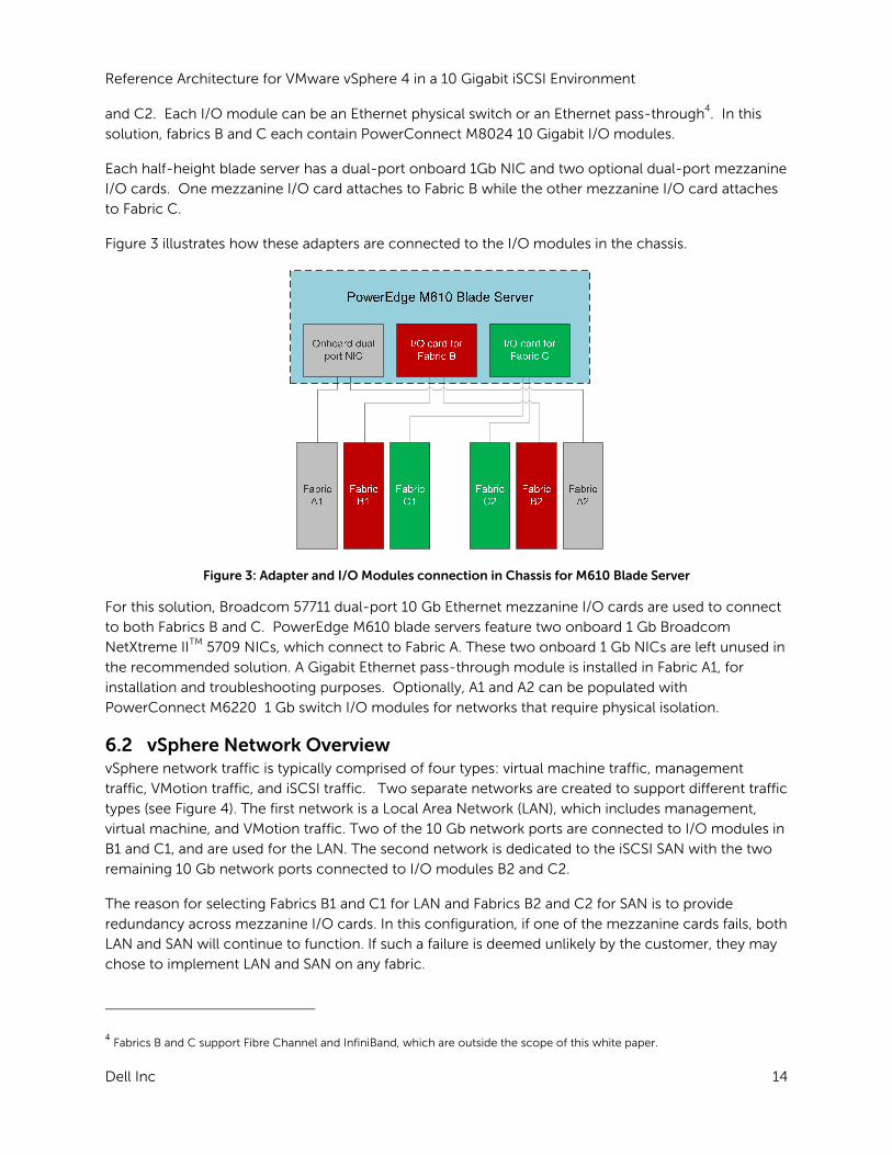
Each half-height blade server has a dual-port onboard 1Gb NIC and two optional dual-port mezzanine
I/O cards. One mezzanine I/O card attaches to Fabric B while the other mezzanine I/O card attaches
to Fabric C.
Figure 3 illustrates how these adapters are connected to the I/O modules in the chassis.
Figure 3: Adapter and I/O Modules connection in Chassis for M610 Blade Server
For this solution, Broadcom 57711 dual-port 10 Gb Ethernet mezzanine I/O cards are used to connect
to both Fabrics B and C. PowerEdge M610 blade servers feature two onboard 1 Gb Broadcom
NetXtreme IITM 5709 NICs, which connect to Fabric A. These two onboard 1 Gb NICs are left unused in
the recommended solution. A Gigabit Ethernet pass-through module is installed in Fabric A1, for
installation and troubleshooting purposes. Optionally, A1 and A2 can be populated with
PowerConnect M6220 1 Gb switch I/O modules for networks that require physical isolation.
6.2 vSphere Network Overview vSphere network traffic is typically comprised of four types: virtual machine traffic, management
traffic, VMotion traffic, and iSCSI traffic. Two separate networks are created to support different traffic
types (see Figure 4). The first network is a Local Area Network (LAN), which includes management,
virtual machine, and VMotion traffic. Two of the 10 Gb network ports are connected to I/O modules in
B1 and C1, and are used for the LAN. The second network is dedicated to the iSCSI SAN with the two
remaining 10 Gb network ports connected to I/O modules B2 and C2.
The reason for selecting Fabrics B1 and C1 for LAN and Fabrics B2 and C2 for SAN is to provide
redundancy across mezzanine I/O cards. In this configuration, if one of the mezzanine cards fails, both
LAN and SAN will continue to function. If such a failure is deemed unlikely by the customer, they may
chose to implement LAN and SAN on any fabric.
4 Fabrics B and C support Fibre Channel and InfiniBand, which are outside the scope of this white paper.

Reference Architecture for VMware vSphere 4 in a 10 Gigabit iSCSI Environment
Dell Inc 15
Design Principles for Network Architecture: The following design principles are used to develop the
network architecture to support the above traffic types:
Redundancy: Both LAN and iSCSI SAN have redundant I/O modules. Redundancy of the network adapters is achieved through NIC teaming at the virtual switch. There is no single point-of-failure.
iSCSI SAN physical isolation: The iSCSI SAN should be physically separated from the LAN to avoid any network congestion.
Logical isolation of VMotion using VLAN: VMotion traffic is unencrypted. It is important to logically isolate the VMotion traffic using VLANs.
Optimal performance: Load balancing is used to achieve the highest throughput possible. Based on these principles, best practices for load balancing, failover, and VLAN configuration are
provided.
This section assumes a certain understanding of networking concepts in a virtualized environment.
See http://www.vmware.com/files/pdf/virtual_networking_concepts.pdf for an overview of VMware’s
networking capabilities.
Figure 4: Overview of Network Configuration
6.3 LAN Architecture The LAN includes virtual machine traffic, management traffic, and VMotion traffic. A virtual switch
(vSwitch0) is created and two 10 Gb physical network ports are connected as uplinks to this virtual
switch. This creates a team of two network ports, enabling NIC failover and load balancing. These
network ports are in turn connected to PowerConnect M8024 I/O modules in slots B1 and C1. Three
port groups are created on vSwitch0: one for the virtual machine network, another for the VMotion
network, and the third for the service console (for ESX) or management (for ESXi). When virtual
machines are created, the virtual network adapters are connected to the virtual machine network port
group.

Reference Architecture for VMware vSphere 4 in a 10 Gigabit iSCSI Environment
Dell Inc 16
Figure 5 illustrates the virtual switch configuration with port groups, and the virtual switch connections
to physical network adapters and I/O modules.
Figure 5: LAN Configuration
6.3.1 Traffic Isolation using VLANs The traffic on the LAN is separated into three VLANs; one VLAN each for management, VMotion, and
virtual machine traffic. Network traffic is tagged with the respective VLAN ID for each traffic type in the
virtual switch. Routing between VLANs is dependent on the specific customer requirements and is not
included in the reference architecture. If desired, the M8024 modules can be easily configured to
provide the routing function.
Trunking must be used so that all the VLANs can share the same physical connection. To achieve this,
all of the internal ports in the two M8024 modules are configured to be in trunk mode.
VMotion traffic is unencrypted, so it is highly recommended to isolate this traffic from the rest of the
network5.
6.3.2 Load Balancing and Failover Load balancing enables sharing of network traffic between the physical network ports in a team,
thereby generating higher throughput. The VMware virtual switch has three options to configure load
balancing:
Route based on the originating virtual switch port ID (default configuration): For outbound
traffic, the physical adapter port is selected based on the hash of the virtual port. This means
that a given virtual network adapter will use only one physical adapter port at any given time to
transmit network packets. Packets are received on the same physical adapter port.
Route based on source MAC hash: Here, the physical port is selected for transmit based on a
hash of the source MAC address. This means that a given virtual network adapter will use only
5 http://blogs.vmware.com/security/2008/02/keeping-your-vm.html

Reference Architecture for VMware vSphere 4 in a 10 Gigabit iSCSI Environment
Dell Inc 17
one physical port at any given time to transmit network packets. Packets are received on the
same physical adapter port.
Route based on IP hash: Here, the physical adapter port is selected for transmit based on a
hash of the source and destination IP addresses. Link Aggregation can be used with this
setting. The physical switch load balancing algorithm will then determine which physical
adapter port is selected to receive the packets. To achieve proper load balancing, both the
virtual switches and the physical switches need to be configured. Note that the virtual switch
and the physical switch hashing algorithms work independent of each other.
The default load balancing configuration of route based on the originating virtual switch port ID is
recommended. Multiple VMs will use different physical adapter ports to transmit and receive traffic.
The service console (for ESX) or management network (for ESXi) has only one port ID or MAC address.
Hence, the service console or management network will use only one physical adapter port for
communicating, unless there is a failover to another physical adapter port.
All the physical network adapter ports will be configured as active by default when load balancing is
enabled.
For VMotion, it is recommended to configure one physical adapter (say vmnic2) as the active adapter
and the other adapter is configured as standby for all the blade servers. This ensures VMotion traffic
will use only I/O module and the traffic can be contained within the chassis, unless there is a failover.
6.3.3 Uplinks Each of the two I/O modules has eight 10 Gb Ethernet ports. Some of these ports can use used for
Inter-Switch Link (ISL). The rest of the ports can be used for the existing network infrastructure in the
datacenter depending on customer requirements.
Example: two 10 Gb ports in each PowerConnect I/O module can be used as uplinks. The two ports
must be a configured using Link Aggregation to provide a redundancy and load balancing.
VLAN and routing must be configured on these uplinks depending on the existing infrastructure
requirements.
6.3.4 Inter Switch Links For a stand-alone configuration without uplinks, the two I/O modules can be connected to each other
using ISLs. The number of ISL connections will depend on the network requirements of the
infrastructure. Using two ISLs will provide bandwidth of 20 Gigabits per second (Gbps) between the
I/O modules which should be sufficient for most cases. The two links are configured using Link
Aggregation.
When connecting to existing infrastructure switches, using ISL between I/O modules will potentially
create loops for using Spanning Tree Protocol (STP). Care must take to provide routing in the existing
infrastructure for VMotion and FT traffic. This depends on the existing infrastructure and outside the
scope of this paper.
6.3.5 vNetwork Distributed Switch It is highly recommended to use vNetwork Distributed Switch in place of the standard virtual switch.
The vNetwork Distributed Switch provides a centralized management interface for configuring virtual
network across multiple ESX/ESXi servers in the cluster.

Reference Architecture for VMware vSphere 4 in a 10 Gigabit iSCSI Environment
Dell Inc 18
Additional features supported in vNetwork Distributed Switch:
Network VMotion (Port state follows VM)
Bi-directional Traffic Shaping
Private VLAN
For more information on the features refer to
http://www.vmware.com/files/pdf/VMW_09Q1_WP_vSphereNetworking_P8_R1.pdf
6.3.6 VMware Traffic Shaping in Virtual Switches Traffic shaping is a feature available in virtual switches that can be used for rate limiting. The standard
vSwitch supports traffic shaping on outbound traffic. The vNetwork Distributed Switch supports traffic
shaping on both inbound and outbound activity. Traffic shaping has three parameters: average
bandwidth, peak bandwidth and burst size. Refer to VMware ESXi Configuration Guide (section “Traffic Shaping”) for more information on these parameters.
Traffic shaping can be used to rate limit the LAN traffic types: VM traffic, VMotion traffic, and
management traffic. Some important things to consider when implementing traffic shaping:
Traffic shaping does not guarantee bandwidth to a certain traffic type, but provides a limit on
the maximum bandwidth that can be transmitted.
Traffic shaping can be used to limit the bandwidth of the non critical traffic. This will enable
the critical traffic to get sufficient bandwidth.
Traffic shaping can be configured per port group on the virtual switch. The same traffic
shaping configuration will be applied to all the ports within that port group. (For example, if the
Virtual Machine port group is set to an average bandwidth of 2 Gbps, all the virtual network
adapters connecting to that port group will have traffic shaping set to an average bandwidth of
2 Gbps).
It is highly recommended to set the traffic shaping parameters to less than 4Gbps, for
consistent behavior. Refer to VMware documentation and Knowledge Base articles for more
information.
6.3.7 VMware Fault Tolerance VMware Fault Tolerance (FT) can be implemented in the proposed solution with a few modifications.
A new port group can be created in the virtual switch for the FT logging network to which traffic
shaping can be applied. When using FT, it is recommended that
In section 6.3.2, we recommended configuring vmnic2 as the active adapter and vmnic4 is configured
as standby in all the blade servers for VMotion traffic. Similarly, for VMware FT, we recommended
configuring vmnic4 as the active adapter, and leaving vmnic2 as standby. This will ensure VMotion and
VMware FT use different physical adapters for communication.
It is important to note the bandwidth requirement for the FT logging network using the following
formula:
VMware FT logging bandwidth ~= (Avg disk reads (MB/s) x 8 + Avg networkinput (Mbps)) x 1.2 [20% headroom]

Reference Architecture for VMware vSphere 4 in a 10 Gigabit iSCSI Environment
Dell Inc 19
Requirements for VMware FT can be found in the VMware white paper: VMware Fault Tolerance
Recommendations and Considerations on VMware vSphere 4.
6.4 iSCSI SAN Architecture In this section, we discuss the best practices for configuring the iSCSI SAN using the software iSCSI
initiator in ESX/ESXi. For detailed instructions on configuring EqualLogic storage with vSphere, refer to
the Technical Report: Configuring VMware vSphere software iSCSI with Dell EqualLogic PS Series Storage6.
Software initiator in the guest OSes is also supported, but is outside the scope of this document.
6.4.1 Inter Switch Links It is important to understand the ISL requirements for switches connected to the EqualLogic storage.
For five or fewer EqualLogic arrays connected to switches, a general recommendation is to have 20
Gbps to 30 Gbps bandwidth between the switches. For six or more arrays, 40 Gpbs to 60 Gbps
bandwidth between the switches is recommended. Note that the ISL requirements may vary
depending on the I/O requirements of the applications running in the virtual machines.
6.4.2 Storage Connectivity Each PowerConnect I/O module contains eight 10 Gb Ethernet ports. Each controller on the Dell
EqualLogic PS6010 Series array has four ports (two active and two passive connections). The two
active ports are split between two different physical switches to provide redundancy. The passive ports
are connected in a similar fashion.
Figure 6 illustrates the connection of two Dell EqualLogic PS6010 Series arrays to a Dell PowerEdge
M1000e chassis. For the sake of simplicity, only connections from the active controller are shown.
The passive controllers are connected in similar fashion.
For connecting more than three arrays, refer to the Scalability section.
6 http://www.equallogic.com/resourcecenter/assetview.aspx?id=8453. Registration is required.

Reference Architecture for VMware vSphere 4 in a 10 Gigabit iSCSI Environment
Dell Inc 20
EqualLogic PS6010XV
EqualLogic PS6010XV
EqualLogic PS6010XV
PowerEdge M1000e
(2) ISLs providing 20 Gbps connectionConnections to Active Controller
Figure 6: Storage Connectivity
6.4.3 Virtual Switch Design A virtual switch (vSwitch1) is created and two 10 Gigabit physical network adapter ports are connected
as uplinks to the virtual switch. These network adapter ports are in turn connected to PowerConnect
M8024 switch I/O modules in Fabrics B2 and C2.
One VMkernel interface is created and associated with one physical network interface. The VMkernel interfaces are used by the software iSCSI initiator to connect to the storage arrays. This is illustrated in

Reference Architecture for VMware vSphere 4 in a 10 Gigabit iSCSI Environment
Dell Inc 21
Figure 7. For detailed discussion regarding configuring VMware iSCSI software initiator, refer to the Technical Report: Configuring VMware vSphere software iSCSI with Dell EqualLogic PS Series Storage7.
Figure 7: iSCSI SAN Configuration
An optional port group can also be created (not shown in the figure) to enable a VM to
monitor/manage the isolated iSCSI network. For example, SAN HQ can be installed in the virtual
machine and used to collect statistics from your Dell EqualLogic PS Series arrays.
6.4.4 vNetwork Distributed Switch The additional features supported by the vNetwork Distributed Switch are listed in section 6.3.5. These
features are not applicable to an iSCSI SAN environment. Hence vNetwork Distributed Switch is not
recommend for iSCSI SAN. However, if it is required in customer environments to simplify
management, it can be used.
6.4.5 VLAN Storage traffic is completely isolated from the other networks. There is no requirement to enable
multiple VLANs for this architecture. The ports on the physical switch can be configured in access
mode. The virtual switch does not have VLANs defined in the port groups.
6.4.6 Jumbo Frames Jumbo frames can be enabled in the iSCSI network to improve performance. Jumbo frames need to
be enabled on the VMkernel interfaces, virtual switches, and PowerConnect switches.
6.4.7 Load Balancing Multipathing is a technique that allows more than one physical path to be used to transfer data
between a host and an external storage device. In version 4.0 of ESXi, VMware provides the VMware
Native Multipathing Plugin. This plugin supports three Path Selection Plugins: Most Recently Used
(MRU), Fixed, and Round Robin (RR). The default selection for a PS6010 volume is Fixed, but this can
be changed to Round Robin for better performance. In Round Robin mode, multiple paths or multiple
7 http://www.equallogic.com/resourcecenter/assetview.aspx?id=8453. Registration is required.

Reference Architecture for VMware vSphere 4 in a 10 Gigabit iSCSI Environment
Dell Inc 22
physical network adapters can be used to access a single iSCSI volume. Figure 8 shows two iSCSI
VMkernel ports and multiple paths accessing a single iSCSI volume simultaneously, thereby enabling
load balancing.
Figure 8: Multipathing using Round Robin
The Dell EqualLogic SAN automatically distributes iSCSI connections between the available two
network interfaces in each controller. It also automatically distributes volumes between different
storage devices in the storage pool. No additional configuration is required.
For a detailed discussion of iSCSI connections, see the VMware ESX/ESXi 4.0 “iSCSI SAN Configuration
Guide”. For a detailed description of how to configure the iSCSI connection, see the section titled “

Reference Architecture for VMware vSphere 4 in a 10 Gigabit iSCSI Environment
Dell Inc 23
Deploying and Configuring the Solution”.
6.4.8 Uplinks The largest implementation of this reference architecture directly connects the blade chassis to three
EqualLogic storage arrays. This is designed for a standalone configuration and there are no available
ports to connect the iSCSI network to an existing infrastructure. The EqualLogic storage should be
managed from the management blade or a management virtual machine in the chassis.
If uplinks are required, or the storage needs to be integrated with an external management
infrastructure, intermediate switches need to be used. The storage arrays can be connected with a
two-tiered architecture. See section 7 for more information on scalability.
6.4.9 EqualLogic Network Requirements In addition to the above guidelines, EqualLogic has specific recommendations for connecting PS
Series arrays to the network. We have highlighted some of the important recommendations below:
Enable Flow Control on each switch port and NIC that handles iSCSI traffic. PS Series arrays will correctly respond to Flow Control.
Do not use Spanning-Tree (STP) on switch ports that connect end nodes (iSCSI initiators or array network interfaces). If use of STP or Rapid STP (which is preferable to STP) is desired, enable the port settings available on some switches that let the port immediately transition into the STP forwarding state upon link up. This functionality can reduce network interruptions that occur when devices restart and should only be enabled on switch ports that connect end nodes. Note: The use of Spanning-Tree for a single-cable connection between switches is
encouraged, as is the use of trunking for multi-cable connections between switches.
Enable Jumbo Frames on the switches, and VMware kernel interfaces. Disable unicast storm control on each switch that handles iSCSI traffic if the switch provides
this feature. The use of broadcast and multicast storm control is encouraged on switches.
For more and latest information, see the Dell EqualLogic PS Quick Start Guide at
https://www.equallogic.com/support/ (Registration is required).
7 Scalability As workloads increase, the reference configuration can be scaled to provide additional resources. This
section provides guidelines for adding blade servers, blade chassis, and storage arrays to the reference
configuration.
7.1 Scaling Compute Resources Adding blade servers: If the cluster has reached or is about to exceed its acceptable maximum
resource utilization, additional blades can be added to the cluster. For quick addition of a new blade
and for the cluster to be uniform, host profiles can be used. A host profile is created from an existing
ESXi blade server on the same cluster. It will capture the networking, storage and security settings
from the validated configuration. An ESXi blade server with basic vSphere installation can be added to
the cluster first. A host profile is then applied to this newly added blade server. Note that host profiles

Reference Architecture for VMware vSphere 4 in a 10 Gigabit iSCSI Environment
Dell Inc 24
do not capture iSCSI network configurations. The iSCSI configuration must be done on each blade
server. Scripts provided in the Appendix can be used for this purpose.
Adding a blade chassis: If the chassis is full of blades and more compute resources are needed, an
additional blade chassis can be added to the solution. Each new chassis will be uplinked to the
external network infrastructure
7.2 Scaling Storage Resources The default solution can have up to three EqualLogic PS 6010 series arrays connected directly to the
chassis. To scale beyond three PS6010 arrays per chassis, intermediate switches are required in the
iSCSI fabric. Two PowerConnect 8024F can be used for intermediate switches, as shown in Figure 9.
PowerConnect 8024F switches must be connected through ISLs. Refer to section 6.4.1 for ISL
requirements for EqualLogic. Figure 9 shows two PowerConnect 8024F switches connected with 4
ISLs providing 40 Gbps of bandwidth. The ISLs are configured with Link Aggregation. PowerConnect
I/O module switches should not have ISLs, since this would create a loop. M8024 switches are
connected to the 8024F switch using links which are configured using Link Aggregation as shown in
Figure 9.

Reference Architecture for VMware vSphere 4 in a 10 Gigabit iSCSI Environment
Dell Inc 25
EqualLogic PS6010XV
PowerEdge M1000e
(4) ISLs providing 40 Gbps connectionConnections to Active ControllerConnections to Passive Controller
Connections between I/O modules and Intermediate switches
PowerConnect 8024F
PowerConnect 8024F
Figure 9: Storage Connectivity with Intermediate Switches
8 Storage Configuration The section provides recommendations for configuring the Storage Array.
8.1 Volume Size Considerations Volume sizes depend on the customer environment and the type of workloads. With the changes in
the iSCSI load balancing architecture for ESX 4.0, the previous recommendation of using multiple
volumes has been removed. Using multiple VMkernels in a “round-robin” setting allows ESX to
establish multiple connections to a single volume. Depending on the environment, you may decide to
create multiple ~500 GB volumes with multiple VMs. It is important to include space for Guest OS
Reference Architecture for VMware vSphere 4 in a 10 Gigabit iSCSI Environment
Dell Inc 26
memory cache, snapshots, and VMware configuration files when sizing the volumes. Additionally, you
can configure thin-provisioned volumes to grow on demand only when additional storage is needed
for those volumes. Thin-provisioning can increase the efficiency of storage utilization. For a detailed
discussion of VMFS considerations, see the VMware “iSCSI SAN Configuration Guide”,
http://www.vmware.com/pdf/vsphere4/r40/vsp_40_iscsi_san_cfg.pdf
8.2 Array RAID Configuration The storage array RAID configuration is highly dependent on the workload in your virtual environment.
The Dell EqualLogic PS Series arrays support four RAID types – RAID 5, RAID 6, RAID 10, and RAID 50.
It is recommended to configure the array in RAID 6 for best performance and capacity. In general,
RAID 10 provides the best performance, at the expense of storage capacity. RAID 50 generally provides
more usable storage, but has less performance than RAID 10 in random I/O situations and requires
additional overhead in the case of a drive failure scenario. RAID 5 provides the most storage capacity
at the expense of a little lower performance and availability, and is not recommended since the
availability of RAID 6.
Reference Architecture for VMware vSphere 4 in a 10 Gigabit iSCSI Environment
Dell Inc 27
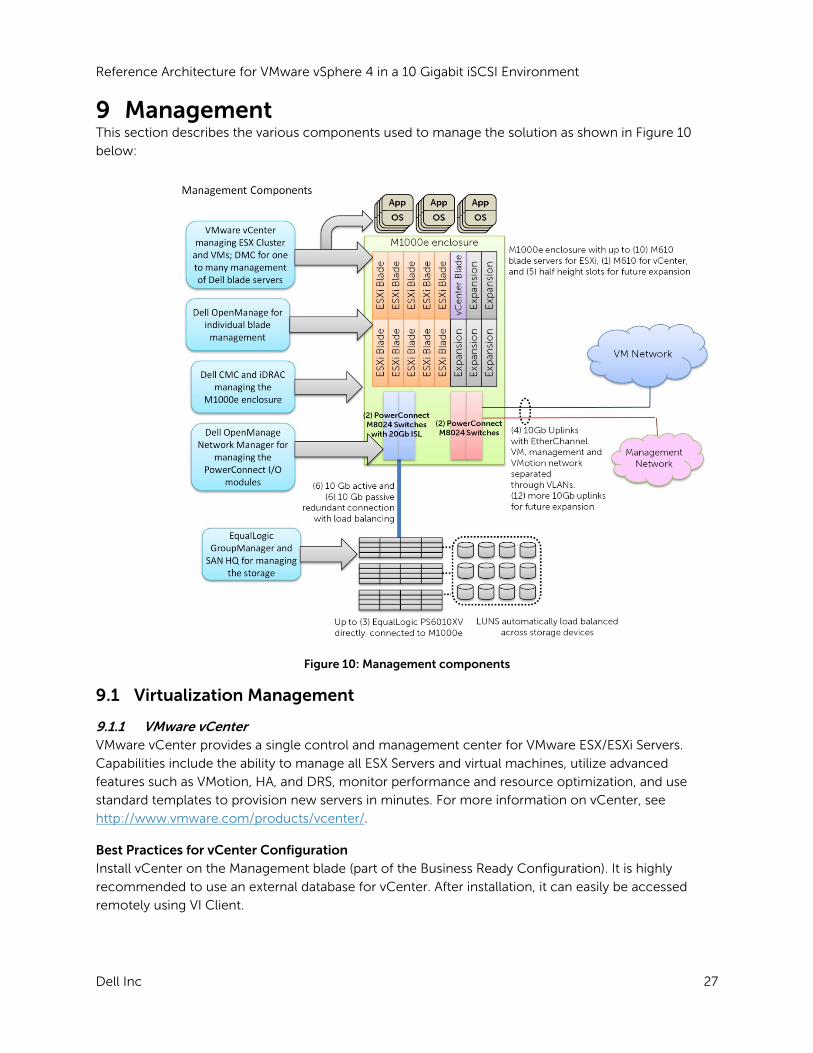
9 Management This section describes the various components used to manage the solution as shown in Figure 10
below:
Figure 10: Management components
9.1 Virtualization Management
9.1.1 VMware vCenter VMware vCenter provides a single control and management center for VMware ESX/ESXi Servers.
Capabilities include the ability to manage all ESX Servers and virtual machines, utilize advanced
features such as VMotion, HA, and DRS, monitor performance and resource optimization, and use
standard templates to provision new servers in minutes. For more information on vCenter, see
http://www.vmware.com/products/vcenter/.
Best Practices for vCenter Configuration Install vCenter on the Management blade (part of the Business Ready Configuration). It is highly
recommended to use an external database for vCenter. After installation, it can easily be accessed
remotely using VI Client.

Reference Architecture for VMware vSphere 4 in a 10 Gigabit iSCSI Environment
Dell Inc 28
For information on Setup and Configuration, see the VMware vCenter Guide at
http://www.vmware.com/products/vcenter-server/resource.html.
vCenter Configuration- High Availability
We have highlighted some of the best practice recommendations for configuring VMware vCenter in a
high availability configuration below:
Install two instances of VMware vCenter in a linked mode configuration on two separate virtual
machines. Make sure that the virtual machines are on to separate ESX hosts to ensure
maximum availability.
Enable mirroring on the external database. Configure the ODBC client on the vCenter virtual
machines, to reflect the primary and mirrored databases.
If the databases are on virtual machines, make sure they are hosted on separate ESX hosts.
This can also be done by the adding a rule to the DRS configuration, to ensure that the virtual
machines are hosted on separate hosts at all times.
Note: This configuration uses an additional management blade which will have to be added to the Business Ready Configuration.
vCenter 1 vCenter 2
VC Database(Active)
VC Database (Mirrored)
Linked Mode
Mirrored
Figure 11: VMware vCenter (High Available) configuration
9.1.2 Platespin Workload Management PlateSpin® Workload Management provides the ability to profile, migrate, protect, and manage server
workloads between physical and virtual infrastructures in heterogeneous IT environments. The
PlateSpin Workload Management portfolio for Dell servers gives Dell customers a powerful data center
management platform for Dell’s 32- and 64-bit Windows and Linux servers with support for leading
hypervisors. For more information on PlateSpin migration tools and other products, see
www.dell.com/platespin.
Reference Architecture for VMware vSphere 4 in a 10 Gigabit iSCSI Environment
Dell Inc 29
9.2 Systems Management The following tools and software can be used to manage the hardware:
Dell OpenManage: Dell OpenManage Server Administrator (OMSA) can be installed on the VMware
ESX/ESXi hypervisor and can be used to manage the hardware. For more information on Dell
OpenManage and its capabilities, see www.dell.com/openmanage.
Deployment and change management using Lifecycle Controller: Dell PowerEdge M610 blade
servers come with USC. This helps reduce operating costs by simplifying deployment and
management. Key features include: Diagnostics, self-update (UEFI, Driver Pack update), firmware
updates (BIOS, NIC FW, RAID Controllers), and hardware configuration.
Out-of-band CMC and iDRAC: The CMC provides a single, secure interface to manage the inventory,
configuration, monitoring, and alerting for chassis components (iKVM, CMC), I/O modules, servers,
and iDRAC. It also provides excellent real-time power management, monitoring, and alerting
capabilities. The Dell chassis provides users with system-level power limiting, slot-based prioritization,
and dynamic power engagement functionalities. The iDRAC on each server provides the flexibility to
remotely manage the server through Console redirection and Virtual CD-ROM/DVD/Floppy/Flash
capabilities.
Dell Management Console: The Dell Management Console (DMC), powered by Symantec, is a
systems management solution designed to provide a central console offering features from basic
hardware management to advanced enterprise functionality. The DMC creates a foundation for more
advanced management functionality and provides a single view into the deployment, inventory,
monitoring, and updating of your IT infrastructure - including servers, storage, desktops, notebooks,
network devices, printers, and other non-Dell devices.
9.3 Storage Management Dell EqualLogic storage arrays provide a rich set of management features that are available at no
additional cost and come with easy-to-use management tools. For more information on features and
management capabilities, see www.dell.com/equallogic.
9.4 Switch Management Dell OpenManage Network Manager is a comprehensive, centralized network management solution
designed to help customers:
Minimize the time, complexity and cost of network management
Increase overall network efficiency
Effectively manage corporate networks across platforms
Maximize your IT investment

Reference Architecture for VMware vSphere 4 in a 10 Gigabit iSCSI Environment
Dell Inc 30
10 Deploying and Configuring the Solution This section provides guidelines for the initial deployment and configuration of the solution.
Rack, Stack, and Cable:
1. Rack the chassis with blade servers and I/O modules. 2. Rack the Dell EqualLogic storage arrays. 3. Connect power to the chassis and storage. 4. Consider PDUs. This document provides detailed information on how to configure the PDUs:
http://www.dell.com/downloads/global/products/pedge/en/pe_m1000e_selection_whitepaper.pdf
5. Cable servers and storage. a. Cable the server and storage for Ethernet connectivity as per the architecture. b. Connect the switches with any required ISLs.
Configuring the Chassis
Configure the Chassis Management Controller using the web interface or the front LCD panel on the
chassis. By default the CMC will get a DHCP address, which you can view from the LCD.
Use static chassis management IP address (preferable). Enable FlexAddressing. Configure the iDRAC IP address for the blades. Configure the PowerConnect Switch Management IP.
Configure Networking
1. Configure the network switch modules. It is recommended that you create a configuration file for the network switches. These files are written in a sparse format using the range command for interfaces.
Configuring the Server
Configure the server either locally or by using the iDRAC Console Redirection remotely. Perform the
following:
Enable VT in the BIOS. For ESXi, it is recommended to have diskless servers. Configure USC for self-update and firmware repository. Boot the ESXi system Assign a password, management IP address, and DNS name to ESXi using the DCUI (Direct
Console User Interface).
Configuring Storage
Configure the Dell EqualLogic PS storage array. For information on configuring storage, see the Dell EqualLogic PS QuickStart Guide at https://www.equallogic.com/support/ (Registration required).
1. Create volumes

Reference Architecture for VMware vSphere 4 in a 10 Gigabit iSCSI Environment
Dell Inc 31
2. Create access list 3. Add the VMkernel iSCSI IPs to the access list. (Use * to denote the IP address range.) 4. Modify the volume settings to allow simultaneous connections from multiple servers
(clusters).
Configuring vCenter
Installing SQL database is required before installing VMware vCenter. See the “ESXi Embedded and
vCenter Server Setup Guide”,
http://www.vmware.com/pdf/vsphere4/r40/vsp_40_esxi_e_vc_setup_guide.pdf to install vCenter on
the management server.
Deployment Steps
1. Create a cluster in vCenter with DRS and DPM features enabled. Add the ESX servers to the cluster.
2. Place the servers in maintenance mode. 3. Configure vNetwork Distributed Switches and add to the server 4. Configure iSCSi using scripts provided in the Appendix. You can run the scripts by
downloading VMware CLI.

Reference Architecture for VMware vSphere 4 in a 10 Gigabit iSCSI Environment
Dell Inc 32
11 References
VMware Documentation
ESXi Configuration Guide http://www.vmware.com/pdf/vsphere4/r40_u1/vsp_40_u1_esxi_server_config.pdf
VMware Virtual Networking Concepts
http://www.vmware.com/files/pdf/virtual_networking_concepts.pdf
What’s new in vSphere Networking
http://www.vmware.com/files/pdf/VMW_09Q1_WP_vSphereNetworking_P8_R1.pdf
VMware Fault Tolerance recommendations and considerations for vSphere
http://www.vmware.com/files/pdf/fault_tolerance_recommendations_considerations_on_vm
w_vsphere4.pdf
EqualLogic Documentation
Configuring VMware vSphere software iSCSI with Dell EqualLogic PS Series Storage
http://www.equallogic.com/resourcecenter/assetview.aspx?id=8453
PS Series Array Network Connection and Performance Guidelines
http://www.equallogic.com/resourcecenter/assetview.aspx?id=5229
Configuring VMware vSphere Software iSCSI with Dell EqualLogic PS Series Storage
http://www.equallogic.com/resourcecenter/assetview.aspx?id=8453
PowerEdge Blade Server
Blade Server Manual http://support.dell.com/support/edocs/systems/pem/en/index.htm
Integrating Blade Solutions with EqualLogic SANs
http://www.dell.com/downloads/global/partnerdirect/apj/Integrating_Blades_to_EqualLogic_
SAN.pdf
12 Feedback We are interested in knowing your feedback to this document. If you identify any errors, including
typographical, grammatical or architectural errors, or if you have any questions, please email us at to
Reference Architecture for VMware vSphere 4 in a 10 Gigabit iSCSI Environment
Dell Inc 33
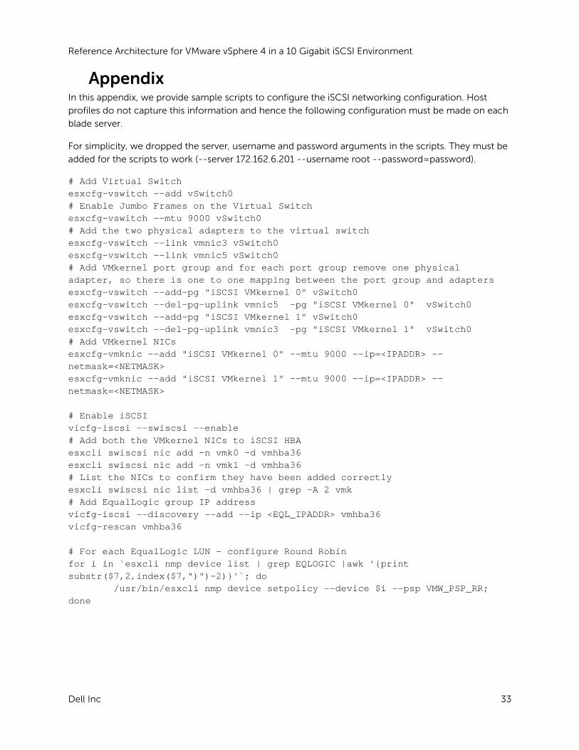
Appendix In this appendix, we provide sample scripts to configure the iSCSI networking configuration. Host
profiles do not capture this information and hence the following configuration must be made on each
blade server.
For simplicity, we dropped the server, username and password arguments in the scripts. They must be
added for the scripts to work (--server 172.162.6.201 --username root --password=password).
# Add Virtual Switch esxcfg-vswitch --add vSwitch0 # Enable Jumbo Frames on the Virtual Switch esxcfg-vswitch --mtu 9000 vSwitch0 # Add the two physical adapters to the virtual switch esxcfg-vswitch --link vmnic3 vSwitch0 esxcfg-vswitch --link vmnic5 vSwitch0 # Add VMkernel port group and for each port group remove one physical adapter, so there is one to one mapping between the port group and adapters esxcfg-vswitch --add-pg "iSCSI VMkernel 0" vSwitch0 esxcfg-vswitch --del-pg-uplink vmnic5 -pg "iSCSI VMkernel 0" vSwitch0 esxcfg-vswitch --add-pg "iSCSI VMkernel 1" vSwitch0 esxcfg-vswitch --del-pg-uplink vmnic3 -pg "iSCSI VMkernel 1" vSwitch0 # Add VMkernel NICs esxcfg-vmknic --add "iSCSI VMkernel 0" --mtu 9000 --ip=<IPADDR> --netmask=<NETMASK> esxcfg-vmknic --add "iSCSI VMkernel 1" --mtu 9000 --ip=<IPADDR> --netmask=<NETMASK> # Enable iSCSI vicfg-iscsi --swiscsi --enable # Add both the VMkernel NICs to iSCSI HBA esxcli swiscsi nic add -n vmk0 -d vmhba36 esxcli swiscsi nic add -n vmk1 -d vmhba36 # List the NICs to confirm they have been added correctly esxcli swiscsi nic list -d vmhba36 | grep -A 2 vmk # Add EqualLogic group IP address vicfg-iscsi --discovery --add --ip <EQL_IPADDR> vmhba36 vicfg-rescan vmhba36 # For each EqualLogic LUN – configure Round Robin for i in `esxcli nmp device list | grep EQLOGIC |awk '{print substr($7,2,index($7,")")-2)}'`; do /usr/bin/esxcli nmp device setpolicy --device $i --psp VMW_PSP_RR; done


![VMware VSphere Architecture [V5.0]](https://static.fdocuments.us/doc/165x107/577cc7071a28aba7119fd0f2/vmware-vsphere-architecture-v50.jpg)