Reference and Instruction Manual Optec Vision...
26
Reference and Instruction Manual Optec ¨ Vision Tester 8623 W. Bryn Mawr Ave., Suite 502, Chicago, IL 60631 USA 1.773.867.0380 or 1.800.344.9500 facsimile: 1.773.867.0388 email: [email protected] www.stereooptical.com STEREO OPTICAL Optec is a registered trademark of Stereo Optical Co., Inc. ¨
Transcript of Reference and Instruction Manual Optec Vision...
Reference and Instruction Manual
Optec¨ Vision Tester
8623 W. Bryn Mawr Ave., Suite 502, Chicago, IL 60631 USA 1.773.867.0380 or 1.800.344.9500 facs imile: 1 .773.867.0388 emai l : sa les@stereooptical .com www.stereooptical .com
STEREO OPTICAL
Optec is a registered trademark of Stereo Optical Co., Inc.
¨
Reference and Instruction Manual
Model 5000 Vision TesterFor Model 5000(P) Manual
&Model 5500(P) Motorized
VisionTester
P/N 32175
8623 W. Bryn Mawr Ave., Suite 502, Chicago, IL 60631 USA 1.773.867.0380 or 1.800.344.9500 facs imile: 1 .773.867.0388 emai l : sa les@stereooptical .com www.stereooptical .com
STEREO OPTICAL
Optec is a registered trademark of Stereo Optical Co., Inc.
¨
Introduction
Good vision is a precious gift, which should be guarded, cherished, and nurtured throughout life. To maintain good vision, frequent vision screenings and periodic visual exams are necessary. In thisway, an awareness of inadequate vision or changes in vision can be noted. The eye-care profes-sional can then correct most visual problems. Without these screenings, many children and adultswould have undetected visual difficulties, having a direct effect on their quality of life.
Eye-care professionals feel that the earlier vision screening can begin, the more rewarding theresults can be. This attention should be continued throughout adult life, with specific attention to theworking years.
Stereo Optical's Model 5000 Vision Tester does this screening efficiently. It is a precision instrument designed to do quick, accurate, reliable, and confidential screening. It will identify thosewho have a problem and need professional assistance.
1
External Features
1. Forehead Activator: Controls illumination inside the Vision Tester. It will only activate the lightswhen the subject maintains pressure against the activator, insuring the subject to be at a proper distance for testing. When forehead pressure is applied to the bar, the green "Ready" indicator willbe illuminated on the control panel and the subject will be ready to be tested.
2. Headrest Tissue: The tissue cushions the subject's forehead while allowing maximum hygienicconditions.
3. Lens System: The upper lenses are for FAR Point testing (simulated distance of 20 ft.) The subject looks straight ahead. The lower lenses are for NEAR Point testing (simulated distance of16 in.) with the subject looking down while holding his/her head straight. The lenses are easily accessible for cleaning and the face plate is wide enough to accommodate wide contemporary eyeglass frames.
4. Instrument Base: It gives a stable foundation for the vision tester in all positions.
5. Elevation Adjustment: Simply depress the button in the base and adjust the instrument to thedesired height for each subject. Release button and the instrument is locked in place.
6. Observation Doors: The observation doors, located on both sides of the unit, allow the tester easyaccess to both FAR and NEAR test slides. A pointer can be used by the tester to assist the subjectin identifying the targets. The pointer is held in place by clips inside the door. The doors are heldclosed with magnets.
7. FAR and NEAR Indicators: These lights indicate how the instrument is set to test accordingly.
8. Test Dial and Knob: Located on both sides of the unit, is used to change slides in the viewingarea. The ribbed knob turns the dial easily and can go forward or reverse. The numbers on the dialcorrespond to the numbers on the record form for identifying the test slide. The number under the litindicator is the number of the test in the viewing area. On the Model 5500 (motor-driven) VisionTester, this small knob should not be used. All slides should be advanced from buttons on theremote control panel.
9. Electronic Control Panel: Operates the functions of the vision tester, power switch, right and lefteye switches, Near and Far switches, and the optional peripheral test controls.
10. Instrument Body: The Instrument Body is lightweight and is made of flame retardant ABS plastic.
11.Carrying Handle: Built-in for maximum convenience. The rigid handle and lightweight body aid inease of portability.
The serial number is located on the inside of the Slide Access Door
2
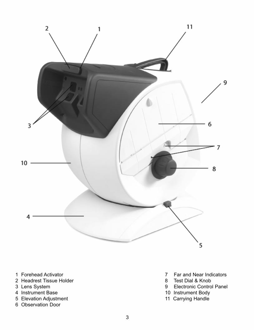
3
1 Forehead Activator 7 Far and Near Indicators2 Headrest Tissue Holder 8 Test Dial & Knob3 Lens System 9 Electronic Control Panel4 Instrument Base 10 Instrument Body5 Elevation Adjustment 11 Carrying Handle6 Observation Door
Internal Features
1. An advanced light system renders a white homogenous light, resulting in high contrast imagesand truer color reproduction.
2. Built-in baffle assembly isolates the left and right eye, thus eliminating unwanted reflective light.By eliminating crossover, true binocular and monocular tests are guaranteed.
3. Front surface mirror offers a ghost-free image for more accurate testing of distance vision.
4. Up to 12 test slides can be mounted on a rotatable drum. The slides can easily be removed orreplaced in seconds.
5. Stereo Optical's slides are manufactured from a high-resolution photographic film mountedbetween 2 layers of glass. The high resolution of (500/line pairs/mm) affords a much finer acuitylevel for more accurate testing.
6. Stereo Optical's slides are transilluminated to eliminate glare and reflection. The result is a moreaccurate image, therefore a more accurate test.
4
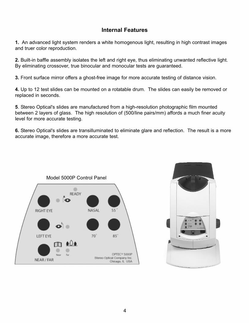
Model 5000P Control Panel
Advanced Design Control Panel
The control panel is designed for convenience in both operation and maintenance. The figure onprevious page shows the control panel for the Model 5000P with perimeter (Non-motorized).
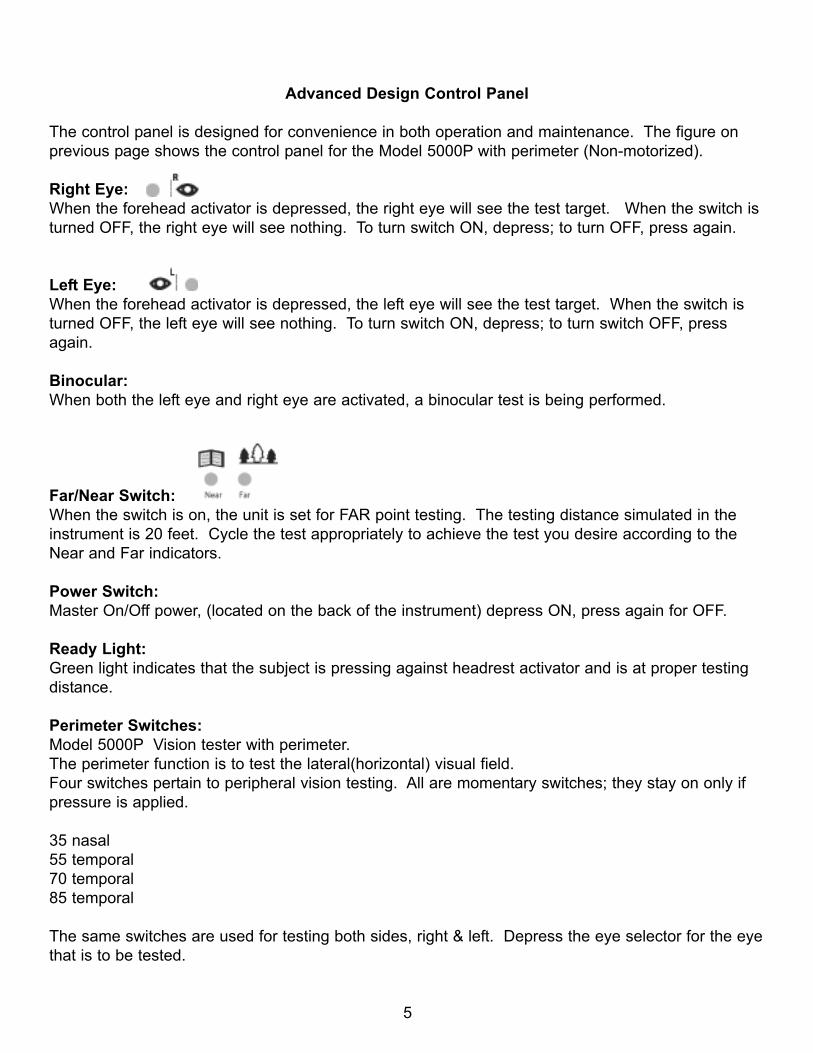
Right Eye:When the forehead activator is depressed, the right eye will see the test target. When the switch isturned OFF, the right eye will see nothing. To turn switch ON, depress; to turn OFF, press again.
Left Eye:When the forehead activator is depressed, the left eye will see the test target. When the switch isturned OFF, the left eye will see nothing. To turn switch ON, depress; to turn switch OFF, pressagain.
Binocular: When both the left eye and right eye are activated, a binocular test is being performed.
Far/Near Switch:When the switch is on, the unit is set for FAR point testing. The testing distance simulated in theinstrument is 20 feet. Cycle the test appropriately to achieve the test you desire according to theNear and Far indicators.
Power Switch:Master On/Off power, (located on the back of the instrument) depress ON, press again for OFF.
Ready Light:Green light indicates that the subject is pressing against headrest activator and is at proper testingdistance.
Perimeter Switches:Model 5000P Vision tester with perimeter. The perimeter function is to test the lateral(horizontal) visual field.Four switches pertain to peripheral vision testing. All are momentary switches; they stay on only ifpressure is applied.
35 nasal55 temporal70 temporal85 temporal
The same switches are used for testing both sides, right & left. Depress the eye selector for the eyethat is to be tested.
5
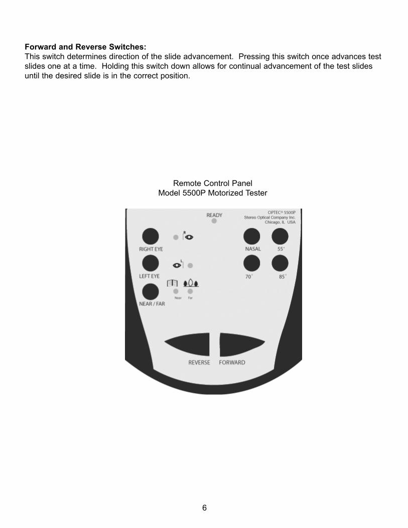
Forward and Reverse Switches:This switch determines direction of the slide advancement. Pressing this switch once advances testslides one at a time. Holding this switch down allows for continual advancement of the test slidesuntil the desired slide is in the correct position.
6
Remote Control PanelModel 5500P Motorized Tester
Vision Testing--The Right Way
Look into the instrument and note what happens when the eye switches are ON and OFF.Experiment with viewing FAR point slides at NEAR point and vice versa, by dialing through all 12slides. First, view all slides in the FAR point mode, and then repeat in the NEAR mode. Note thatFAR test slides viewed at NEAR are upside-down, as are the NEAR test slides viewed at FAR. It isimportant to recognize whatever the subject may be describing and be able to answer any questions. Concentrate on acquiring a smooth delivery of instruction and description of the test target, as well as confidence in handling the instrument. The tester's administrative expertise canhelp relax the subject, achieve cooperation, and a more accurate response.
When speaking to the subject, never act surprised or provoked by their response or lack ofresponse. Give the subject every opportunity to demonstrate his/her best vision.
If the subject normally wears glasses or contact lenses, he/she should wear them during the testingto determine whether or not his/her prescription is still adequate.
Select a table or counter of convenient height with sufficient surface space for the instrument andthe recording of these results. Normal room lighting is acceptable, but care should be taken to avoidlight shining on the lenses or on the subject's face.
IMPORTANT CHECKPOINTS:
-Be certain the instrument is plugged into a 110/120VAC Outlet.
-Adjust instrument to proper height for subject's comfort by depressing button on base and movingthe housing.
-Push power switch on back of instrument to activate the instrument.
-Tear off headrest tissue, so a clean tissue is ready for the subject.
-Be certain the subject presses their forehead against the headrest activator so the illumination inthe unit is activated and the GREEN "READY" indicator on the control panel is lit.
-Be certain the subject is comfortable.
-Be certain to have a clean record form and a scoring marker.
You are now ready to test
7
Model 5000(P) Peripheral Test
This is a test of peripheral vision on the horizontal plane. The lights flash at 85, 70, and 55 degreestemporally and approximately 35 degrees nasally, so a possible total of 120 degrees arc for eacheye can be attained. (Highest temporal reading plus nasal reading.)
Caution should be taken because the temples of eyeglass frames could interfere with this test. Thetest should be taken with eyeglasses on and again with the glasses off to determine if the frameinterferes with peripheral vision.
To administer the test:1. FAR Switch ON2. RIGHT Eye switch ON3. LEFT Eye switch OFF4. Dial #1 at Yellow Indicator
Subject should look straight ahead, through the FAR lens system, with his/her forehead against theheadrest activator. Ask the subject to look at slide #1. Then ask the test subject to point his fingerin the direction he sees the light. The test administrator will then press one of the four switches, oneyellow, and three blue, on the lower half of the control panel. The switches can be pressed in anyorder and should be held down for two or three seconds. Repeat the test with the left eye by turningthe RIGHT occluder OFF and the LEFT occluder ON.
NOTE: This test can be administered to a one-eyed person. In this case, the nasal test becomesvery important because it will determine if there is peripheral vision on the blind side.
8
Maintenance of your Model 5000 Vision Tester
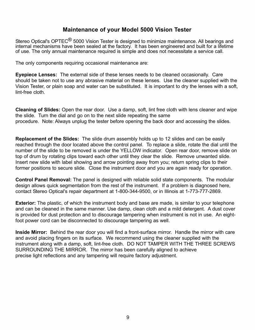
Stereo Optical's OPTEC® 5000 Vision Tester is designed to minimize maintenance. All bearings andinternal mechanisms have been sealed at the factory. It has been engineered and built for a lifetimeof use. The only annual maintenance required is simple and does not necessitate a service call.
The only components requiring occasional maintenance are:
Eyepiece Lenses: The external side of these lenses needs to be cleaned occasionally. Careshould be taken not to use any abrasive material on these lenses. Use the cleaner supplied with theVision Tester, or plain soap and water can be substituted. It is important to dry the lenses with a soft,lint-free cloth.
Cleaning of Slides: Open the rear door. Use a damp, soft, lint free cloth with lens cleaner and wipethe slide. Turn the dial and go on to the next slide repeating the same procedure. Note: Always unplug the tester before opening the back door and accessing the slides.
Replacement of the Slides: The slide drum assembly holds up to 12 slides and can be easilyreached through the door located above the control panel. To replace a slide, rotate the dial until thenumber of the slide to be removed is under the YELLOW indicator. Open rear door, remove slide ontop of drum by rotating clips toward each other until they clear the slide. Remove unwanted slide.Insert new slide with label showing and arrow pointing away from you; return spring clips to their former positions to secure slide. Close the instrument door and you are again ready for operation.
Control Panel Removal: The panel is designed with reliable solid state components. The modulardesign allows quick segmentation from the rest of the instrument. If a problem is diagnosed here,contact Stereo Optical's repair department at 1-800-344-9500, or in Illinois at 1-773-777-2869.
Exterior: The plastic, of which the instrument body and base are made, is similar to your telephoneand can be cleaned in the same manner. Use damp, clean cloth and a mild detergent. A dust coveris provided for dust protection and to discourage tampering when instrument is not in use. An eight-foot power cord can be disconnected to discourage tampering as well.
Inside Mirror: Behind the rear door you will find a front-surface mirror. Handle the mirror with careand avoid placing fingers on its surface. We recommend using the cleaner supplied with theinstrument along with a damp, soft, lint-free cloth. DO NOT TAMPER WITH THE THREE SCREWSSURROUNDING THE MIRROR. The mirror has been carefully aligned to achieve precise light reflections and any tampering will require factory adjustment.
9
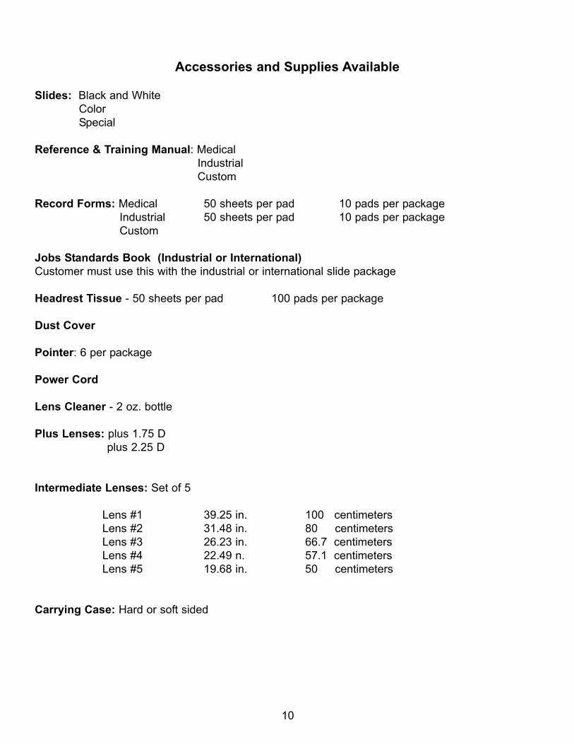
Accessories and Supplies Available
Slides: Black and WhiteColorSpecial
Reference & Training Manual: MedicalIndustrialCustom
Record Forms: Medical 50 sheets per pad 10 pads per packageIndustrial 50 sheets per pad 10 pads per packageCustom
Jobs Standards Book (Industrial or International)Customer must use this with the industrial or international slide package
Headrest Tissue - 50 sheets per pad 100 pads per package
Dust Cover
Pointer: 6 per package
Power Cord
Lens Cleaner - 2 oz. bottle
Plus Lenses: plus 1.75 Dplus 2.25 D
Intermediate Lenses: Set of 5
Lens #1 39.25 in. 100 centimetersLens #2 31.48 in. 80 centimetersLens #3 26.23 in. 66.7 centimetersLens #4 22.49 n. 57.1 centimetersLens #5 19.68 in. 50 centimeters
Carrying Case: Hard or soft sided
10
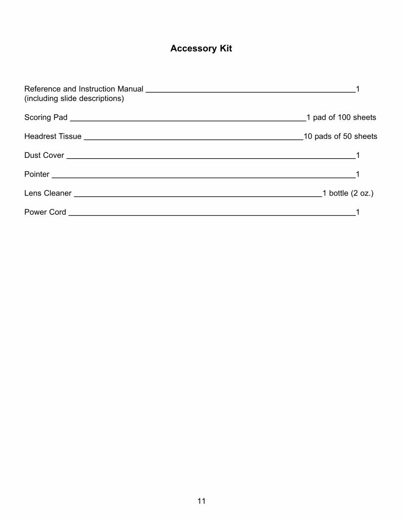
Accessory Kit
Reference and Instruction Manual 1(including slide descriptions)
Scoring Pad 1 pad of 100 sheets
Headrest Tissue 10 pads of 50 sheets
Dust Cover 1
Pointer 1
Lens Cleaner 1 bottle (2 oz.)
Power Cord 1
11
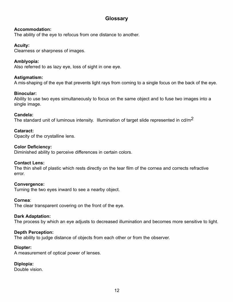
Glossary
Accommodation:The ability of the eye to refocus from one distance to another.
Acuity:Clearness or sharpness of images.
Amblyopia:Also referred to as lazy eye, loss of sight in one eye.
Astigmatism:A mis-shaping of the eye that prevents light rays from coming to a single focus on the back of the eye.
Binocular:Ability to use two eyes simultaneously to focus on the same object and to fuse two images into a single image.
Candela:The standard unit of luminous intensity. Illumination of target slide represented in cd/m2
Cataract:Opacity of the crystalline lens.
Color Deficiency:Diminished ability to perceive differences in certain colors.
Contact Lens: The thin shell of plastic which rests directly on the tear film of the cornea and corrects refractiveerror.
Convergence: Turning the two eyes inward to see a nearby object.
Cornea:The clear transparent covering on the front of the eye.
Dark Adaptation:The process by which an eye adjusts to decreased illumination and becomes more sensitive to light.
Depth Perception:The ability to judge distance of objects from each other or from the observer.
Diopter:A measurement of optical power of lenses.
Diplopia: Double vision.
12
Divergence:The process of directing two eyes from a near point to a far point.
Esophoria:The tendency of the eye to pull inward on the horizontal plane.
Exophoria:The tendency of the eye to pull outward on the horizontal plane.
Far Point: Twenty feet to infinity.
Fixation:Directing the eye so the image centers on the fovea.
Focus:The point at which light rays will come together after passing through a lens.
Fusion:Power of coordination by which images received by two eyes become a single image.
Hyperopia:Farsightedness, the images focus behind the retina.
Hyperphoria:When either eye has a tendency to pull up on the vertical plane.
Intermediate Vision:Vision which focuses at some point beyond 18 inches or 45 centimeters (Near Point) and less than20 feet or 6 meters (Far Point).
LUX: The unit for measuring of glare.
Malingerer:A person who pretends to have a vision problem.
Mesopic: Pertaining to illumination between the photopic and scotopic ranges.
Monocular:Seeing with only one eye.
Muscle Balance:The coordination of muscles allowing two eyes to work together on the vertical and lateral planes.
13
Myopia:Nearsightedness; has problem seeing at a distance; images focus in front of the retina.
Near Point:14 to 16 inches or 35 to 40 centimeters.
Occlusion:Obscuring the vision of an eye.
Orthophoria:Expected or normal teamwork of the eyes.
Peripheral Vision:Ability to perceive the presence, motion, or color of objects outside the direct line of vision.
Phoria: Root word denoting a latent deviation in which the eyes have a constant tendency to turn from thenormal position for binocular vision.
Photopic:Vision under bright lighting levels.
Potential Acuity:A quick assessment of macular function in cataract patients and documents that surgery is expectedto impove visual performance.
Presbyopia:Loss of accommodation so it is difficult to focus on near objects.
Refraction: The bending of the rays of light. Sometimes used to refer to an examination for glasses or contactlenses.
Scotopic:Vision at low light levels.
Stereopsis:The ability to perceive depth.
Strabismus:A muscle imbalance. Eyes turn inward or outward.
Suppression:The non-use of vision in one eye.
Vision:The ability to see and to interpret what is seen.
Visual Acuity:Vision of an eye or eyes.
14
Safety Aspects
Use this device properly and safely.
Before use or maintenance, read this manual.
This operator's manual contains information necessary for the operation of the OPTEC VisionTester.This manual includes operating procedures, safety precautions, and specifications. IEC standardsare applied in this manual.
Safety Precautions
In this manual, a signal word is used to designate the degree or level of safety alerting. The defini-tions are as follows.
CAUTION Indicates a potentially hazardous situation which, if not avoided, may result in minor ormoderate injury or property damage accident.
Even situations indicated by "CAUTION" may result in serious injury under certain conditions. Safetyprecautions must be strictly followed at all times.
Handling Precautions
Before use of instrument
CAUTION
-Do not use the device for other than its intended purpose.
STEREO OPTICAL will assume no responsibility for accident or malfunction caused by improperuse.
·Never modify or touch the internal structure of the device.
Electric shock or malfunction may resultThere are no user-serviceable parts inside the device.
·Verify that the following specified environmental conditions for installation are met. In addition, verifythat usage area meets the following conditions.
15
Make certain that the instrument is operated in the following environment conditions:
Humidity 30% to 75% No large amount of dust is contained in the airSubdued ambient lightLocate instrument in a place free from vibration or impactLocate instrument on a stable surface
·Be sure that a power outlet meets the power requirements.
If the supplied voltage is too high or low, the device may not deliver full performance and malfunc-tion, or fire may result.
·Be sure to use the power supply that came with the device. Using any adapter other than the sup-plied one may result in malfunction, or may void the warranty.
·Do not use an extension cord when supplying the device with the power.
·Be sure to connect using a grounded outlet. Electrical shock or fire may result in event of malfunc-tion or electrical leakage.
·Never crush or pinch the power cord with heavy objects. Damage may result in electrical shock orfire.
·Before connecting cables to the device turn the instrument OFF and disconnect the power cord ofthe power supply from the power outlet.
Usage Precautions
CAUTION
The device has been tested and found to comply with the limits for the medical devices to the IEC60601-1-2 and EN55011. These limits are designed to provide reasonable protection against harmfulinterference in a typical medical installation. This device generates, uses and can radiate radio fre-quency energy. If not installed and used in accordance with the instructions, may cause harmfulinterference to other devices in the vicinity. However, there is no guarantee that the interference toother devices, which can be determined by turning the device off and on, is caused by this instru-ment. The user is encouraged to try to correct the interference by one or more of the followingmeasures :
- Reorient or relocate the receiving device.
- Increase the separation between the device.
16
- Connect the device into an outlet on a circuit different from that which was previously used.
- Consult STEREO OPTICAL for help.
-Connect the cable to the interface connector securely, maintaining the correct orientation of theconnector of the cable.
Proper data communication with an external computer will not perform if the internal wires of thepower cord are exposed, power to the device is interrupted by moving the cord, or the plug or cordbecomes extremely hot, this indicates that the cord is damaged. Immediately replace the powercord.
In case of malfunction, immediately unplug from the power outlet and contact your authorized dis-tributor for replacement; otherwise, electric shock or fire may result.
-In the event that a strange odor or smoke is noticed coming from the device, turn it off and unplugthe power cord immediately. After confirming that the odor or smoke is no longer being produced,contact you authorized distributor. Continued use may result in electric shock or fire.
17
Maintenance
CAUTION
·Only service technicians trained properly by STEREO OPTICAL may service the device.STEREO OPTICAL assumes no responsibility for accidents resulting from improper servicing.
·There are no user-serviceable parts inside the device.
·All returns must have a Return Material Authorization number
Disposal
·Follow local governing ordinances and recycling plans regarding disposal or recycling of devicecomponents. It is recommended to commission the disposal to a designated industrial waste dis-posal contractor.
·When disposing of packing materials, sort them by material and follow local governing ordinancesand recycling plans
Before use : Device Description
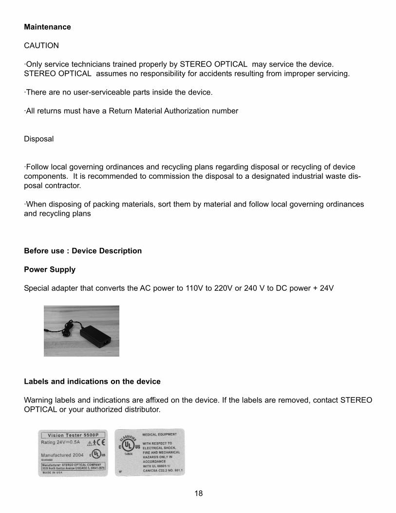
Power Supply
Special adapter that converts the AC power to 110V to 220V or 240 V to DC power + 24V
Labels and indications on the device
Warning labels and indications are affixed on the device. If the labels are removed, contact STEREOOPTICAL or your authorized distributor.
18
Maintenance
Troubleshooting
In the event that the device does not work correctly, correct the problem according to the followingtable before contacting your authorized distributor.
Suggested action:If the device will not work at all- Make sure that the power cord is connected properly- Make sure that the cord of the power supply is connected properly. Make sure that the voltageapplied to the power outlet is within the specified range.
Contact STEREO OPTICAL or your authorized distributor if the above suggestions do not eliminatethe corresponding problem.
Cleaning
When the cover or panels of the device becomes soiled, wipe with a soft cloth. For stubborn soiling,immerse the cloth in a neutral detergent diluted with water, wring it well, and wipe. Finally wipe witha dry, soft cloth.
CAUTION
·Never use an organic solvent such as paint thinner.The surface of the device may be damaged.
·Never use a sponge or cloth containing excessive moisture to wipe the device.The water may leak into the inside of the device and cause device malfunction.
·If the fixation lamps are smeared, proper measurements cannot be performed.
19
Specifications and classifications
Classifications
[Classification under the provision of 93/42/EEC (MDD)] Class IThe OPTEC Vision Tester is classified as a class I
[Type of protection against electric shock]The OPTEC Vision Tester is classified as Class I
A Class I is a device in which the protection against electric shock does not rely on basic insulationonly, but which includes an additional safety precaution in such a way that means are provided forthe connection of the device to the protective (ground) conductor in the fixed wiring of the installationin such a way that accessible metal parts cannot become live in the event of a failure in the basicinsulation.
[Degree of protection against electrical shock] Type B Applied PartThe OPTEC Vision Tester is classified as a device with a Type B Applied Part.A Type B Applied Part provides a particular degree of protection against electrical shock, particularlyregarding the following :- allowable leakage currents- reliability of the protective earth connection (if applicable)
[Degree of protection against the entrance of liquid] IP20 *1
The OPTEC Vision Tester is classified as an ordinary device without protection against liquid intru-sion. Avoid exposing water or other liquid to the device.
20

NOTES
21

NOTES
22

NOTES
23